1
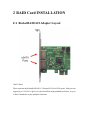
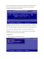
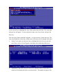
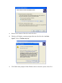
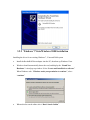
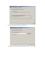
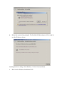
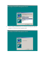
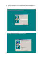
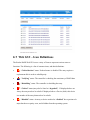
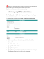
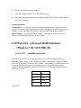
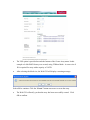
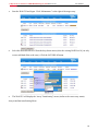
4 Bay eSATA RAID 0/1/10/5/JBOD SUB SYSTEM
w/ 6G PCIe Card
RSV-S4-6G
User Manual
Content
1
WELCOME............................................................................................................................. 4
1.1
1.2
1.2.1
1.2.2
1.2.3
1.3
1.4
1.5
1.6
1.7
1.7.1
2
RAID CARD INSTALLATION .......................................................................................... 11
2.1
2.2
2.3
2.4
2.4.1
2.4.2
2.4.3
2.4.4
2.4.5
2.4.6
2.4.7
3
PRECAUTION..................................................................................................................... 4
FEATURES .......................................................................................................................... 5
DATA SECURITY ............................................................................................................. 5
DATA PERFORMANCE ................................................................................................... 5
DATA VERSATILITY....................................................................................................... 5
EASE OF USE ...................................................................................................................... 6
SPECIFICATIONS.............................................................................................................. 6
SUPPORTED OPERATING SYSTEMS ........................................................................... 7
PRODUCT CONTENTS ..................................................................................................... 7
RAID CARD INTRODUCTION ........................................................................................ 8
FEATURES AND SPECIFICATIONS............................................................................... 8
ROCKETRAID 622 ADAPTER LAYOUT ............................................................................. 11
INSTALLING THE ROCKETRAID RR622 HOST ADAPTER ............................................... 12
VERIFYING INSTALLATION ................................................................................................ 12
ROCKETRAID BIOS UTILITY ........................................................................................... 13
BIOS SETTINGS OVERVIEW........................................................................................ 13
USING THE BIOS UTILITY ........................................................................................... 14
BIOS COMMANDS ......................................................................................................... 14
CREATING RAID ARRAYS ........................................................................................... 14
DELETING ARRAYS ........................................................................................................... 17
ADDING/REMOVE SPARE DISKS ........................................................................................ 19
SETTINGS ........................................................................................................................... 20
ROSEWILL SOFTWARE CD ............................................................................................ 21
3.1 DEVICE DRIVER INSTALLATION ........................................................................................ 21
3.2 ROCKETRAID RR622 WINDOWS DRIVER INSTALLATION ............................................. 21
3.2.1 WINDOWS XP, 2003 .......................................................................................................... 21
3.2.2 WINDOWS 7/VISTA/WINDOWS 2008 INSTALLATION ........................................................ 24
3.3 LINUX AND FREEBSD DEVICE DRIVER INSTALLATION ................................................... 28
4
ROSEWILL RAID MANAGEMENT UTILITIES (HRM) – WEB GUI / CLI .............. 29
4.1 WINDOWS OPERATING SYSTEMS – INSTALLING THE WEB GUI FROM THE SOFTWARE
CD. 29
4.2
RED HAT ENTERPRISE/CENTOS, FEDORA CORE, OPEN SUSE – INSTALLING THE WEBBASED MANAGEMENT UTILITY ................................................................................................... 29
4.3 DEBIAN/UBUNTU LINUX DISTRIBUTIONS – INSTALLING THE WEB-BASED
MANAGEMENT UTILITY............................................................................................................... 31
4.4 LINUX DISTRIBUTIONS – COMMAND LINE INTERFACE (CLI)......................................... 31
4.5 INSTALLING THE WEB GUI (V1.5) - WINDOWS OPERATING SYSTEMS (2000, XP, 2003,
VISTA, 2008, WINDOWS 7) ........................................................................................................... 32
4.6 STARTING THE WEB GUI................................................................................................... 37
4.7 WEB GUI – ICON DEFINITIONS ......................................................................................... 38
4.8 WEB GUI - CONFIGURING AN ARRAY ............................................................................... 39
4.8.1 INITIALIZING A NEW HARD DRIVE ..................................................................................... 39
4.8.2 CREATE AN ARRAY ........................................................................................................... 40
4.9 WEB GUI - CONFIGURING SPARE DISKS .......................................................................... 43
4.9.1 TO ASSIGN A SPARE DISK: ................................................................................................. 44
4.10 WEB GUI - RECOVERING AN ARRAY .............................................................................. 46
4.10.1 TO REBUILD AN ARRAY: .................................................................................................. 46
4.11 WEB GUI - MAINTAINING RAID ARRAYS ...................................................................... 48
4.11.1 SCHEDULING TASKS:....................................................................................................... 48
4.11.2 REMOVING TASKS ........................................................................................................... 49
4.11.3 SHI – STORAGE HEALTH INSPECTOR .............................................................................. 49
4.12 WEB GUI - SAFEGUARDING YOUR ARRAY ..................................................................... 50
4.12.1 AUTOMATIC RAID REBUILDING ..................................................................................... 51
4.13 WEB GUI - EVENT NOTIFICATION .................................................................................. 52
4.13.1 CONFIGURING SMTP (E-MAIL) NOTIFICATION............................................................... 53
4.14 WEB GUI - ADVANCED RAID FUNCTIONS (WINDOWS VSS, OCE/ORLM) ................ 54
4.14.1 VSS – VARIABLE SECTOR SIZE ....................................................................................... 54
4.14.2 ONLINE CAPACITY EXPANSION AND RAID LEVEL MIGRATION (OCE/ORLM) ............ 59
5
5.1
MAC OS X DRIVER AND WEB-BASED RAID MANAGEMENT UTILITY.............. 63
MAC OS X DRIVER AND RAID MANAGEMENT INSTALLATION ...................................... 63
1 WELCOME
RSV-S4-6G enhances your data storage by combining advanced RAID 1 features
typically seen on high-end data systems with low cost/high capacity Serial ATA drives.
By using industry standard SATA drives and Hard Driver Controller Adapters, you can
achieve extraordinarily low costs while remaining assured that your data is protected
against hardware failure.
1.1 PRECAUTION
Please read the safe precautions carefully before you using RSV-S4-6G storage
appliance. Ensure that you use the product correctly according to the procedure described
in this guide.
The following safety precautions are intended to remind you to operate the product safely
and correctly. Please read and ensure that you understand them before you proceed to the
other sections of this guide.
z
Do not attempt to disassemble or alter any part of the product that is not describe in
this guide.
z
Do not allow the product to come into contact with water or other liquids. In the
event that water or other liquids enter the interior, immediately unplug the product
from the computer. Continued use of the product may result in fire or electrical
shock. Please consult your product distributor or the closest support center.
z
Do not handle the product near a heat source or expose them to direct flame or heat.
z
Never place the product in close to equipment generating storage electromagnetic
fields. Exposure to strong magnetic fields may cause malfunctions or corrupt data.
z
1
Can’t operate properly under Windows 3.x/ 95 / 98SE/ ME/ NT.
Redundant Array of Independent Devices, a method of combining drives to provide better protection and/or performance. z
Hard disk drive is not including.
1.2 FEATURES
1.2.1 DATA SECURITY
The RSV-S4-6G software driver includes support for monitoring to predict suspect
drives.
RSV-S4-6G provides our highest commitment to data security through the use of RAID
architecture to back up and protect data. RAID levels 1, 10, and 5 provide data security.
RSV-S4-6G supports sophisticated sparing support so that hardware failure risk can be
minimized by automatically regenerating the failed disk’s data on a backup disk. The
RSV-S4-6G software driver includes support for Self-Monitoring Analysis and Reporting
Technology (S.M.A.R.T. 2 ) to predict disk failures. Drives can be moved between
controllers without losing data.
1.2.2 DATA PERFORMANCE
The RSV-S4-6G can also increase storage throughput by combining the throughput of
multiple drives into a single volume. RAID levels 1, 10, and 5 support this ability.
Furthermore, each volume can be tailored to provide the best performance for the data
contained on that disk.
1.2.3 DATA VERSATILITY
The RSV-S4-6G software driver also supports Contiguous and Concatenated drives for
applications which do not require increased security or performance.
2
Self Monitoring, Analysis and Reporting Testing.
1.3 EASE OF USE
The RSV-S4-6G utility offers an easy to use utility for creating and managing your
storage. It also supports the latest SATA enhancements including SATA-II Port
Multiplier support, and up to 3Gbit/sec transfer rates on controllers that support that
speed. Creating and deleting volumes is also possible without requiring a restart of the
operating system and rebuilds never require the data to be taken off-line.
Drives can also be moved between controllers without losing the data.
1.4 SPECIFICATIONS
z
Bundled with dual-port eSATA 6Gb/s PCIe 2.0 x1 RAID controller card for over
200MB/s RAID 5 performance.
z
Power and host status LED, and devices status and activity LED.
z
Metal chassis (SECC) and plastic panel frame (ABS) design.
z
5.3"W x 7.1"H x 10.0"D, Weight: 5.9 lbs.
z
Dual-port RocketRAID 622 eSATA 6Gb/s PCIe 2.0 x1 RAID controller supports up
to 2 units or 8 hard drives in a single or multiple RAID array.
z
Backward compatible with PCIe 1.0.
z
Supports RAID 0, 1, 10, 5, 5+ spare, spanning and JBOD.
z
Supports online expansion to expand capacity without the need to recreate the RAID
volume and erase the existing data.
z
Built-in real time hard drive health monitoring and e-mail notification for critical
events.
z
Supports PC, Linux and MAC OS, including Windows 7 and Snow Leopard.
z
Accesses four hard drives using only one cable.
z
Host interface: eSATA with Port Multiplier.
z
Drive interface: 4 x 3.5" SATA I / SATA II.
z
150 watts, 100 & 240 Vac / 50~60Hz with FCC, CE requirement.
z
Single packing (color box with handle) and 4 in 1 outer box.
1.5 SUPPORTED OPERATING SYSTEMS
The following operating systems are supported by the RSV-S4-6G software driver.
z
Windows XP, 2003, Windows Vista, Windows 2008, Windows 7 (32 and 64-bit
versions)
z
Linux (Fedora Core, Red Hat Enterprise / CentOS, SuSE, Debian Ubuntu)
z
Mac OS X 10.5.x and above (RocketRAID 622)
z
FreeBSD
1.6 PRODUCT CONTENTS
The following parts are content.
z
RSV-S4-6G x1
z
Dual-port RocketRAID 622 eSATA 6Gb/s PCIe 2.0 x1 RAID controller x1
z
eSATA Cable x1
z
AC Cable x1
z
Screw set x 1
z
Quick Installation Guide x1
z
Setup and Installation Driver Repository CD x1
1.7 RAID CARD INTRODUCTION
SATA Revision 3.0, provides dramatically improves performance by doubling the
bandwidth available for storage devices to 600MB/s.
The RR622 is the premier SATA 3.0 RAID host adapter for connecting internal or
external SATA devices. The RR622 is designed to optimize storage performance and
redundancy with RAID levels 0, 1, 5, 10, and JBOD. Storage connected directly to the
RR622 data ports delivers the highest performance while external disk enclosures with
port multiplier device enable higher storage capacities.
The RR622 is accompanied by the Rosewill RAID Web Management interface - a smart
and user-friendly application designed to manage and maintain storage in Windows,
Linux, FreeBSD or Mac OS X operating systems.
1.7.1 FEATURES AND SPECIFICATIONS
Host Adapter Architecture
z
PCI -Express 2.0 x1 (compatible with PCI-Express 1.0)
z
600MB/s per port
z
Supports up to 2 SATA 6Gb/s or 3Gb/s hard disks (up to 10 HDDs w/ port
multiplier support)
z
Multi adapter support: up to 4 adapters
z
RoHS compliant
Advanced RAID Features
z
Supports RAID 0, 1, and JBOD (RAID 5 and 10 if port multiplier enclosure is
available)
z
XOR RAID Engine
z
Multiple RAID array support
z
Multiple Logical Drive Support
z
BIOS booting support
z
BIOS PnP and BBS (BIOS boot specification)support
z
Write through and write back cache
z
Online array roaming
z
Online capacity expansion (OCE) and Online RAID level migration (ORLM)
z
Quick and Background initialization for instant RAID configuration
z
Automatic RAID rebuild
z
64bit LBA support greater than 2TB per volume
z
S.M.A.R.T monitoring hard drive status for reliability
z
Staggered Drive Spin-up
z
(MAID) spin down drives in array when idle
z
ATA pass-through mode support
z
Firmware update while running the Operating System
Array Monitors, Alerts and Indicators
z
SMTP for email notification
z
Alarm/ Buzzer alerts for drive failure
z
SHI – Storage Health Inspector (S.M.A.R.T. and disk maintenance)
RAID Management (HRM)
z
Hot key (ctrl-h) boot-up RAID manager via BIOS
z
Web browser-base RAID management software (Web GUI)
z
Command Line Interface (CLI)
Operating System Support
z
Windows XP, 2003, Windows Vista, Windows 2008, Windows 7 (32 and 64-bit
versions)
z
Linux (Fedora Core, Red Hat Enterprise / CentOS, SuSE, Debian Ubuntu)
z
Mac OS X 10.5.x and above (RocketRAID 622)
z
FreeBSD
Physical Specifications
Operating Temperature
z
Working Temperature +5C ~ +40C
z
Storage Temperature: -40C ~ 60C
z
Relative Humidity Range: 20% ~ 80% non-condensing
Operating Voltage
z
PCI+3.3V: 3.3A, Power: 10W
Dimensions
z
67.5 (H) x 72.0 (L) mm
z
2.66 (H) x 2.84 (L) inch
Kit Contents
z
RocketRAID Host Adapter
z
User’s Guide
z
RAID Management and Device Driver CD
z
2 SATA cables
z
Low-profile bracket
2 RAID Card INSTALLATION
2.1 RocketRAID 622 Adapter Layout
eSATA Ports:
These represent the RocketRAID 620’s 2 External SATA (eSATA) ports. Each port can
support up to 1 SATA 3.0 gb/s or 6.0 gb/s hard disks using standard enclosures, or up to
5 disks if attached to a port multiplier enclosure.
2.2 Installing the RocketRAID RR622 Host
Adapter
Note: Make sure the system is powered-off before installing the RocketRAID RR622
host adapter.
1.
Open the system chassis and locate an unused PCI-E (2.0 or 1.0) x1, x4, x8 or x16
slot.
2.
Remove the PCI slot cover.
3.
Gently insert the RocketRAID RR622 into the PCI-E slot, and secure the bracket to
the system chassis.
4.
After installing the adapter, attach the SATA cables to the RocketRAID 62x’s
SATA ports, and to the hard disks.
5.
Close and secure the system chassis.
2.3 Verifying Installation
Once the RocketRAID host adapter and hard drives have been installed into the chassis,
boot-up the system to verify that the hardware is properly recognized.
1.
Power on the system. If the system detects the presence of the adapter, the
RocketRAID BIOS Utility will be displayed during boot up.
2.
Press Ctrl+H to access the RocketRAID BIOS Utility.
The BIOS Utility will display information about hard disks attached to the adapter. Make
sure all attached disks are detected by this utility. If any of the hard drives are not
detected, power down the system and check the cable connections to both the card, and
enclosure.
2.4 RocketRAID BIOS Utility
The RocketRAID RR622 card will display it's BIOS screen during the system's boot
process.
Press Control + H when prompted, to access the BIOS settings Menu.
2.4.1 BIOS SETTINGS OVERVIEW
The RocketRAID RR622 BIOS utility is an interface that provides management
commands and controller related settings.
2.4.2 USING THE BIOS UTILITY
The following keys utilized by the RocketRAID RR622 BIOS utility:
Alt – press Alt to highlight the tool bar.
Arrow keys – use these to move between different menu items
Enter – Open the selected toolbar command/execute the selected command.
Esc – move back to the previous menu, cancel the selected operation, or exit the BIOS
Utility.
2.4.3 BIOS COMMANDS
Create - this command is used to open the RAID Creation menu.
Delete - this command will delete the selected RAID array.
Add/Remove Spare - this command is used to assign hard disks to function as spare
disks. The controller is capable of using spare disks to automatically rebuild broken or
faulted RAID arrays.
Settings - this command opens the settings menu (selecting the boot disk/array, staggered
drive spinup)
View – this command is used to select between two views: Devices (HARD DISKS),
and Arrays (configured RAID arrays).
Initialize - this command is used to prepare disks for use with RAID arrays. Disks must
be initialized before they can be used to create arrays.
2.4.4 CREATING RAID ARRAYS
Initializing Disks:
Before creating a RAID array, the disks must be initialized. Disk initialization writes
necessary RAID configuration information to the hard disks. Select the Initialize
command from the toolbar, and press ENTER.
Highlight the target disks using the arrow keys, then select using Enter. A numeral will
be displayed before each selected disk. Once all target disks have been selected, press
ESC. The utility will display a warning, and ask you to press Y (yes) to initialize, or N
(no) to cancel. Once initialized, these disks can be used to create RAID arrays.
Warning: Initialization will destroy all pre- existing data on the selected hard disks.
Only initialize disks that do not contain critical data
Creating Arrays:
1.
Select Create from the toolbar and press Enter.
2.
Use the arrow keys to select the RAID level and press ENTER.
Use the arrow keys to highlight the Array Name option and press Enter. The array name
dialogue box will appear. Use the keyboard to input a new Array Name, and press the
Enter key.
Note: the Array Name command is optional – it is not necessary to name the array. The
array can be named at a later time, and the name of the array can be changed at any time.
3.
On the Create menu, use the arrow keys to highlight the Select Devices item and
press Enter. A device list will appear, and display all available hard disk drives.
4.
Highlight the target disks that you want to use, and press Enter to select them. A
numeral will be displayed before each selected disk. This number designates disk
order. After all of the disks have been selected and press the ESC key to return to
the Create Menu.
5.
Next, Use the ↓ arrow key to highlight the Capacity (GB) option and press Enter.
The total available capacity will be displayed. Press ENTER if you wish to use all
available space. If you wish to reserve disk space for additional arrays/single disks,
use the keyboard to input the amount of space (in GB) you wish to set aside for this
particular array, and press Enter.
Note: Multiple arrays can be created using the same set of hard disk drives. The Capacity
option allows you to set aside disk space that be used to create another array, set as a
spare disk, or partitioned to act as a single disk (by the operating system).
6.
For redundant RAID arrays (RAID 1, 5, 10), select the Cache Policy:
Write Back – utilizes disk cache (higher performing)
Write Through – writes directly to the disks (may reduce the risk of data loss during a
critical failure, but at the cost of lower performance).
7.
Sector Size – Also known as “Variable Sector Size”. Use this option if you are
using an older 32-bit Windows operating system. This allows older operating
systems to support volumes over 2TB in size. Do not use if the operating system
already supports large volumes (such as GPT).
8.
To complete the creation procedure, use the arrow key to highlight the Start
Creation item and press Enter. Press the Y (yes) key to create the array, or N (no)
key to cancel the creation process.
2.4.5 Deleting Arrays
Highlight the Delete command from the toolbar, and press Enter.
The BIOS utility will display a list of available RAID arrays. Select the array you wish to
delete, and press Enter.
The utility will display a warning message. Press Y (yes) to delete the array, or select N
(no) to cancel.
Warning: all data stored on the array will be lost – do not delete if the array contains
critical data.
2.4.6 Adding/Remove Spare Disks
This Add/Remove Spare command is used to assign a hard disk to act as a Spare Disk.
Spare Disks are used to automatically rebuild Redundant RAID arrays (RAID 1, 5, 10) in
the case of disk failure. As with creating RAID arrays, disks must be initialized before
they can be used as spares. To set a hard disk to act as a Spare Disk, use the arrow keys
to select the target disk from the list of initialized disks, and press Enter. To remove the
Spare Disk setting from a hard disk, highlight the spare disk, and press Enter.
Generally, single disks are designated to act as spares (disks that are not configured into
RAID arrays).
However, in some instances, disks that are members of RAID arrays may also be
designated to act as a spare. If the disks in question are part of a RAID array that did not
utilize the full available capacity at the time of creation, these disks may be used as
spares. For example: a RAID 0 array was created between two 200GB hard disks, but
only 200GB of space (out of a grand total of 400GB), was assigned to that array. In this
example, 200GB of disk space remains unallocated. This unallocated space would allow
these disks to be set as spares for a separate redundant array that falls into the same
capacity range (200GB).
2.4.7 Settings
To access the Settings menu, highlight the Settings command from the toolbar, and press
Enter.
Select Boot Device – select which disk or array will act as the boot disk, if the
motherboard BIOS instructs the card to act as the boot device.
Staggered Drive Spinup – This option is disabled by default. Enabling this setting will
instruct the card to power up the hard disks, sequentially (one disk approximately every 2
seconds). Not all disk support this setting – consult the disk documentation for more
information.
Warning: Western Digital hard disks do not support this setting. Enabling this setting is
not recommended. If enabled, these disks may not be detected by non-RAID controllers.
3 Rosewill Software CD
Each retail box includes a copy of the Rosewill Products Software CD. This CD contains
drivers for different operating systems, and installing the Rosewill RAID Management
Utility Suite for a variety of operating systems.
3.1 Device Driver Installation
We recommend visiting the Rosewill download pages for the latest Windows Device
Driver updates.
3.2 RocketRAID RR622 Windows Driver
Installation
3.2.1 Windows XP, 2003
Installing the RocketRAID driver for an existing Windows system
After the operating system has booted, the Hardware Wizard will detected the card and
request that the Device Driver be installed.
1.
When the “Found New Hardware Wizard” window appears and asks to search
online, select “No, not this time”.
2.
Select “Install from a list or specific location (Advanced)”, and click Next to
continue.
3.
Click on the “Include this location in the search” option, and click “Browse”.
4.
Browse to the location of the driver and click Next.
5.
Windows will display a warning message that states the driver has “not been
signed”. Select “Continue Anyway”.
6.
Click finish when prompted. When Windows asks to reboot the system, choose Yes.
3.2.2 Windows 7/Vista/Windows 2008 Installation
Installing the driver for an existing Windows 7, Vista and 2008 system
1.
Install the RocketRAID host adapter into the PC, then boot up Windows Vista.
2.
Windows should automatically detect the card, and display the “Found New
Hardware” wizard pop-up window. Select “Locate and install driver software”.
When Windows asks: “Windows needs your permission to continue”, select
“continue”.
3.
When asked to search online select “Don’t Search Online”.
4.
Select “I don’t have disc, show me other options”.
5.
And then select “Browse my computer for driver software”.
6.
Browse to the location of the driver and click “Next”.
7.
When asked: “Would you like to install this driver software?”, select “Install”.
8.
Reboot the system when prompted. The RocketRAID host adapter will be ready for
use after Windows reboots.
Installing the driver during a fresh Windows 7, 2008, Vista installation
1.
Boot from the Windows Installation DVD.
2.
When the screen “where do you want to install Windows” appears, click “Load
driver” and browse for the driver location. Windows can install drivers from several
media types: floppy diskette, USB flash disk or CD.
3.
Select the RocketRAID RR622 controller driver, and click “Next”.
4.
The driver is now installed – the disk or array will be recognized as available disk
space. Windows setup will then proceed normally.
3.3 Linux and FreeBSD Device Driver installation
Binary and source driver updates are routinely posted for a variety of older Linux
operating systems including past versions of Red Hat Enterprise, CentOS, OpenSuSE,
and Fedora Core.
Drivers are also available for several FreeBSD revisions, and are available from the
Rosewill support page:
Several driver sets are included with the Rosewill Software CD.
Each binary driver and source package includes an installation guide.
4 Rosewill RAID Management
Utilities (HRM) – Web GUI / CLI
The Rosewill RAID Management Utility Suite, also known as “HRM”, includes several
user interface options. The latest version of the Web Management utility user manual is
available from our website.
4.1 Windows Operating Systems – Installing the
Web GUI From the Software CD.
Please go to WebGUI Folder for the setup of the WebGUI files.
4.2 Red Hat Enterprise/CentOS, Fedora Core,
Open SuSE – Installing the Web-based
Management utility
Linux operating systems that support .rpm packages, allow you to double-click the
Rosewill Web RAID Management .rpm file to start the installation process.
1.
Copy the Web RAID Management package from the Software CD, to the desktop of
the Linux operating system.
2.
Extract the .tbz file to the desktop, and browse to the appropriate .rpm file (there are
32 and 64-bit options).
3.
Double click the .rpm file – this should open the operating systems software
installer. Enter the Administrative password when prompted and proceed with
installation.
4.
The package can also be installed manually, using a terminal. Log on in as “root”,
open a terminal, and browse to the location of the .rpm file. Run the following
command:
5.
# rpm -i hptsvr-https-1.4-10.i386.rpm (or hptsvr-https-1.4-10.x86_64.rpm)
Note: The i386 rpm package can also work on 64-bit systems if you have 32-bit runtime
libraries installed. If you use the x86_64 rpm package, please make sure the controller
driver has 64-bit ioctl support.
4.3 Debian/Ubuntu Linux Distributions –
Installing the Web-based Management Utility
For Debian/Ubuntu Linux distributions, you can use alien to convert the rpm packages to
a .deb package, then use "dpkg -i" command to install each package. Some script files
may be lost during the conversion process from rpm to .deb, so you may need to make
manual corrections. .
The following files will be installed / configured:
/usr/bin/hptsvr
/etc/hptcfg
- service program
- service config file
/etc/rc.d/init.d/hptdaemon
- service control script
/usr/share/hpt/webguiroot
- data files
If there is no /etc/hptcfg present, you can add it manually using by using the “echo”
command on the driver file name to /etc/hptcfg.
For example:
# echo hptiop.ko >/etc/hptcfg
Uninstalling the Utility
Open a terminal, and use the following command:
# rpm -e hptsvr-https
4.4 Linux Distributions – Command Line
Interface (CLI)
Command Line interface versions of the RocketRAID management utilities are available
for Linux and FreeBSD operating systems.
These packages are posted on the Rosewill website, under the download page for the
products.
4.5 Installing the Web GUI (v1.5) - Windows
Operating Systems (2000, XP, 2003, Vista,
2008, Windows 7)
1.
After downloading the Web GUI, double-click the zip file to view the contents.
Double-click “Setup” to start installation. If you are running a 64-bit version of
Windows 7, 2008 or Vista, you may need to right-click the icon, and select “Run as
Administrator.”
2.
Click “Run” to continue:
3.
The Rosewill Web RAID Management Service install screen will display. Click
Next to continue:
4.
Click Yes to install the Management utility:
5.
Specify the Destination folder and click Next:
6.
Confirm the install location, and click Next:
7.
Choose to enable or disable Remote Access. Remote access allows the card to be
managed via a Web browser from a separate system.
8.
Specify the listening port. 7402 is the default setting, and recommended for most
systems.
9.
Click OK to complete the installation procedure:
4.6 Starting the Web GUI
1.
Double-click the “Rosewill Web RAID Management” Icon on the the Desktop to
start the Web GUI. The system’s default Web Browser will open the following
page:
2.
Type in the default username and password to start the Web GUI:
Username: RAID
Password: hpt
Note: The password can be changed using the “Settings” menu from the toolbar.
3.
Click Login. The Manage – Array screen will be displayed:
4.7 Web GUI – Icon Definitions
The Rocket RAID Web GUI uses a variety of Icons to represent various states or
functions. The following is a list of common icons, and their definitions.
1.
:“Critical-broken” status. Fault-tolerance is disabled. The array requires a
replacement disk in order to rebuild parity.
2.
:“Verifying” status. The controller is checking the consistency of RAID data.
3.
:“Rebuilding” status. The controller is rebuilding the array.
4.
:“Critical” status (may also be listed as “degraded”). If displayed above an
Array: the array needs to be rebuilt. If displayed above a Device (disk): this device
is a member of the array that needs to be rebuilt.
5.
:“Disabled” status. An array or device marked as “disabled” has experienced a
major hardware or parity error, and is hidden from the operating system.
6.
:This icon is shown when an array is being initialized. There are two types of
RAID initialization: The first is known as “foreground” – the controller will write
“0’s” to the array disks. The array cannot be used until this procedure is complete.
The second is “background” – the card will rebuild the parity data, while enabling
access to the array.
7.
:“Uninitialized” status. If displayed above an Array, this Array requires
initialization (see number 6, above). If it appears above a Device(
), the disk is
considered new – it must be initialized before it can be used to create an array.
8.
:This shows that Array is performing an OCE/ORLM procedure.
9.
:This shows the OCE/ORLM procedure has been stopped or paused.
10.
:This icon is displayed above ”Legacy Disks” – non-RAID disks (
). The
controller will assign this status to disks that contain valid partition tables and/or
useable data.
11.
:This icon is displayed above “spare” (
) disks。The controller will use
spare disks to automatically rebuild a critical array.
4.8 Web GUI - Configuring an Array
This guide assumes that the hard disks have already been installed into the external
chassis, and attached to the card. These hard disks must be initialized before they can be
configured as arrays.
4.8.1 Initializing a new hard drive
Use the Initialize Devices option to prepare hard disks for use (creating arrays, rebuilding
arrays, expanding arrays, Spare disks).
1.
Open the Web GUI interface, log-on, and select “Manage”, then “Device” from the
toolbar:
2.
Click the “Initialize Devices” button towards the top of the screen:
3.
This will open a small menu. Check the box before the disk you wish to initialize
and press “Submit”. The initialized disk can now be added to the array.
Note: initializing disks will delete all data from the selected disks.
4.8.2 Create an Array
To create an array, select Manage – Array from the Web RAID Management Utility’s
toolbar. This will open the Manage Array menu:
To create an array:
1.
Select the desired RAID level from the Array Type drop down menu:
2.
Name the array – enter a name for the array, using the Array Name filed (optional).
3.
When creating a Redundant Array (RAID 1, 3, 5, 10, 50), specify an initialization
method. Select Background of Foreground from the drop down menu:
No Initialization: Not recommended for most configurations. This option will not build
parity. Select this when testing storage. The array must be verified manually if this
option is selected
Foreground: The RAID initialization process will be set as high priority. The array
cannot be utilized this procedure is complete, but the build process will take considerably
less time, as the host adapter will dedicate it’s resources to completing this task. This is
most secure option.
Background: This option lowers the priority of RAID initialization. This option will
start to build parity like the Foreground option, but at a lesser rate of speed. This option
allows the array to be accessed immediately. However, as a result, protection against
data loss is much lower compared to the Foreground option.
4.
If you are creating a Redundant Array (RAID 1, 5, 10), specify the array’s Cache
Policy. If you are creating a JBOD or RAID 0 array, skip to step 6. Select WriteBack or Write-Through from the drop down menu:
Write Back – this setting is best for optimal transfer rates, and fully utilizes the available
memory to enhance read and write performance. However, this option raises the risk of
data loss in the event of hardware failure.
Write Through – this option raises the level of data security. Data is written directly to
disk when this Cache Policy is enabled.
However, this lowers the overall performance of the array, when compared to Write
Back.
5.
Assign hard disks to the array. To add a hard disk to the array, check the box
displayed before each disk’s entry. You can also use the “Select All” button to
quickly select all disks attached to the host adapter.
6.
Specify the capacity. Manually enter the desired RAID capacity (in MB). If you
wish to use all available hard disk capacity, leave the “Maximum” entry in place,
and proceed to the next space. If you choose to specify the capacity, make a note
that the remaining capacity (unused space) can be used to configure additional
arrays, or set to act as a “spare” disk.
7.
Once all of the RAID parameters have been specified click the “Create” button to
create the array. The utility will display a brief summary after successfully creating
the array:
4.9 Web GUI - Configuring Spare Disks
The term “Spare Disk” refers to a hard disk, or dedicated disk space, that is used to
rebuild a RAID array in the case of hard disk failure. If free ports/channels are available,
spare disks are ideal for minimizing g downtime – the administrator does not have to
work directly with the storage devices, nor install or remove any additional hardware in
order to rebuild parity.
Spare disks can be created from available hard disks (disks that have been initialized) or
free disk space (unallocated space on a set of RAID disks – leftover space not assigned to
an active array).
To configure Spare Disks, select Manage – Spare from the utility tool bar:
4.9.1 To assign a Spare disk:
1.
Click on the box displayed before the target disk entry, under the Available Disks
section, and click the “Add Spare” button:
2.
Click “OK” when the pop-up window is displayed. This will add the disk to the
Spare Pool.
3.
To remove a Spare Disk from the Spare pool, click the box before the target Spare
Disk, and click the “Remove Spare” button:
The disk will be moved to the “Available Disk” Section
4.10 Web GUI - Recovering an Array
When a redundant array’s status is ”Critical”, fault tolerance is disabled. The array is can
be used in this format, but should be rebuild as soon as possible. If a Spare disk was
configured, the RocketRAID 620 will use this disk to automatically rebuild the array. If a
spare is not available, the array can be rebuilt manually.
If Auto-Rebuild is enabled, simply install a new disk – the RocketRAID 620 will
initialize the drive, and initiate the rebuild process. If the setting is not enabled, follow
the steps below.
4.10.1 To rebuild an array:
1.
Click “Maintenance” towards the right of the target array.
2.
Click “Add Disk”.
3.
Select the desired drive and click “submit.
4.
The Web GUI will initiate the rebuild procedure, and display a progress bar.
4.11 Web GUI - Maintaining RAID Arrays
Regular scheduled RAID Maintenance is essential to data security. We recommend
routine RAID verification sessions to ensure the parity of redundant arrays is properly
synchronized. Unsynchronized arrays face an elevated risk of data loss in the event of
hardware failure, even if the array itself is left intact.
To schedule maintenance sessions, or “Tasks”, select the “Task” option from the utility
toolbar.
This will open the Tasks List and Health Inspector Scheduler page:
4.11.1 Scheduling Tasks:
1.
Enter a name for the task in the “Task Name” field.
2.
Specify the frequency of this task. Click the open circle before the desired
frequency (Daily, Weekly, Bi-Weekly or Monthly).
3.
Specify the time. Select the day from the drop-down menu, then enter the desired
time in the provided fields. Note: the Health Inspector Scheduler works from a 24hr clock (3PM is represented as hour “15”, for example).
4.
Once the task has been named and scheduled, click the “Submit” button to add the
task to the Task List.
4.11.2 Removing Tasks
From the task List, Check the box before the target Task and click “Delete”.
4.11.3 SHI – Storage Health Inspector
The Storage Health Inspector section provides real-time device related information
including temperature readings, bad sector counts, and access to SMART data.
Click “SMART” besides each disk to see its SMART attribute status.
SMART attributes vary based on the disk model and manufacturer. This information is
reported by the drives themselves – SHI simply displays and organizes this data. If any
attribute is reported to have failed, or generated an error, we would recommend
contacting the disk manufacturers for additional technical support, and service
recommendations.
4.12 Web GUI - Safeguarding your Array
The RocketRAID Host Adapter provides a number of innovative maintenance and
notification features designed to help streamline the administration of critical data
storage, and minimize downtime in the case of a major hardware failure. To access these
features, select Settings – System from the utility toolbar:
4.12.1 Automatic RAID Rebuilding
Automatic RAID rebuilding can save an administrator considerable time when servicing
a failed redundant array, virtually eliminating downtime.
This feature instructs the Host Adapter to automatically initiate a rebuild procedure for a
failed redundant array, when the Administrator inserts a new hard disk, using the card’s
Hot Swap (Recan) options.
Simply inset the new hard disk and click “Rescan” from the Manage – Array page.
The host adapter will handle the rest.
Click on the drop down menu provided for “Auto Rebuild”. Select “Enabled” and click
on the “Submit” button.
Enable Audible Alarm – enable or disable the card’s alarm. The alarm will sound if the
disk or array stops responding.
Event Log Path – Use this to select the location of the Web GUI’s event log.
Enable Continue to Rebuild on Error – this setting is disabled by default. We do not
recommend using unless replacement disks are unavailable, or if recommended by a
Customer Support technician.
Set Rebuild Priority – The default setting is Medium. Alter this setting to lower or raise
the priority of an Initialization, Rebuild or Verification session. A lower setting devotes
resources to other systems tasks. A higher setting prioritizes the RAID maintenance
session
Power Saving – Spin-down of idle disks (MAID)
This feature allows the card to safely power down RAID arrays when not in use.
Allowing idle disks to spin down minimizes the power consumption of the system’s
storage devices.
In addition to saving energy, spinning down unused disks reduces mechanical wear and
the buildup of waste heat, which in turn, can greatly prolong the life of the system’s
storage hardware, over the long-term.
Click on the drop down menu provided for “Spin down idle disk (minutes)”, and select
a time (in minutes). This determines when Host Adapter will power down idle hard
disks.
Click the “Submit” button to activate this feature.
SAF-TE – This setting is related to the system chassis. The RR622 models do not
support this option.
Listeneing Port – This item is the card’s port address. 7402 is the default setting.
Password – Use this feature to change the Administrator’s password. The default
password is “hpt”.
4.13 Web GUI - Event Notification
The RocketRAID RR622 host adapters will record Administrator activity or RAID
related errors to the Web GUI’s Event Log. Data recorded to the event log is classified as
an “event”. From the toolbar, click “Event”.
The Event Log records and presents three types of “Events”:
Information: Information data includes all general user/administrator activity
(creating/deleting arrays, configuring spares, rebuilding arrays, configuring event
notification and maintenance tasks, etc.).
Warning: Warning data includes alerts issued by the Host Adapter (SMART/SHI
warnings including temperature and sector alerts, unresponsive hard disks,
unsynchronized parity due to a verification failure, etc.)
Error: Error data includes instances of hardware related problems, such as hard disk
failure, broken arrays, card related problems (BBU, memory failure).
Note: Press the Clear button to delete the current event log
4.13.1 Configuring SMTP (E-mail) Notification
The Web GUI provides an SMTP notification system – this feature can be used to
instruct the Web GUI to send Event data to an Email address. This feature is useful for
remote maintenance sessions.
To configure E-mail notification, select Settings – Email from the utility toolbar:
1.
Enable event notification – click on the box provided before “Enable Event
Notification”.
2.
Enter the E-mail Server Address.
3.
Specify the E-mail “From” address.
4.
Specify the user login name.
5.
Specify the user’s password (this is required by some E-mail servers – consult your
IT department or E-mail service provide fore more information).
6.
Specify the SMTP port (25 is default).
7.
Click the “Submit” button to save the SMTP settings.
8.
Enter the recipient addresses under “Add Recipient”, and click the “Submit” button
to save these settings.
Additional options:
Test Recipient - You can test a recipient’s address using this option – this will send a
default test message to the selected E-mail address, and display a Pass/Fail message. If it
is unable to send a message (Fail) double- check the SMTP and recipient settings.
Delete recipient – to remove an E-mail recipient, check the box provided before the
target E-mail address and click the “Delete” button.
4.14 Web GUI - Advanced RAID Functions
(Windows VSS, OCE/ORLM)
4.14.1 VSS – Variable Sector Size
Variable Sector size allows you specify the sector size when creating a RAID array.
This feature allows older, 32-bit versions of Windows 2000 and XP to support volumes
over 2TB. This feature is limited to data volumes – boot volumes are still limited to 2TB
in size. In addition, some types of data management or backup software may not
recognize the array properly, as they were designed to work with the default Window’s
sector size of 512B.
Sector Size Capacity
Using VSS
512B
2TB
1K
2-4TB
2K
4-8TB
4K
8-16TB
1.
The VSS option is provided towards the bottom of the Create Array menu. In this
example a 4-disk RAID 0 array was created, using 1TB hard disks. A sector size of
1K is required for array with a capacity of 1-4TB.
2.
After selecting the block size, the Web GUI will display a warning message:
Select OK to continue. Click the “Create” button once more to create the array.
3.
The Web GUI will notify you that the array has been successfully created. Click
OK to confirm.
4.
After creating the array, access the Windows Disk Management utility. Click the
“Start” button and select “Control Panel”.
5.
Double-click “Administrative Tools”.
6.
Double-Click “Computer Management”.
7.
Under “Storage”, click on the folder icon labeled “Disk Management”. Disk
Management should open the Disk Wizard. Click “Next” to initialize the new
volume.
Disk Management
8.
Click “Next” to continue
9.
Click “Finish” to continue.
10.
Right-click the “Unallocated” box and select “New Partition”.
11.
Partition and format the array as desired.
4.14.2 Online Capacity Expansion and RAID Level Migration
(OCE/ORLM)
OCE/ORLM allows you to add hard disks to an existing RAID array, and/or convert the array to another
RAID level. Data stored on the array is not lost during this procedure. The procedure described below
documents the expansion of a 3-disk 2TB RAID 5 array to a 4-disk, 3TB RAID 5 array. NOTE:
OCE/ORLM will not work with Mac OS X – this operating system will be unable to expand the
partitions of expanded/migrated RAID arrays.
4 Bay SATA to eSATA 3.5” HDD RAID Storage System RSV-S4-6G
User Manual
1.
Start the Web GUI and logon. Click “Maintenance” to the right of the target array.
2.
Select the desired RAID level from the drop down menu (select the existing RAID level if you only
want to add hard disks to the array). Click the OCE/ORLM button.
3.
The Web GUI will display the “Array Transforming” menu (similar to the create array menu).
Array transform/transforming Menu
60
4 Bay eSATA RAID 0/1/10/5/JBOD SUB SYSTEM w/ 6G PCIe Card RSV-S4-6G
1)
User Manual
Target Name – The GUI will ask that you enter a “new” name for reference (the previous
RAID configuration will be displayed until the procedure is complete). The name can be
changed after the array has been fully expanded / migrated.
2)
Specify the Cache policy (Write Back is default).
3)
Specify the block size (note: not available for all controller models – check the product
documentation).
4.
4)
Select the existing RAID disks, and the disks you wish to add to the array.
5)
Specify the capacity. Maximum (all available space assigned to the array) is default.
6)
Click “Create” to start the expansion/migration process.
The Web GUI will notify you when the process starts. A progress bar will be displayed under the
Status column of the Manage-Array menu.
61
4 Bay SATA to eSATA 3.5” HDD RAID Storage System RSV-S4-6G
5.
User Manual
After the expansion/migration process is complete, Disk Management should recognize the
additional capacity. You are free to create a second partition, or expand the existing partition.
Notes:
z
Bootable volumes should not be expanded beyond 2TB – Windows will not recognize the
additional capacity.
z
Older 32-bit versions of Windows (2000, XP) limit capacity to 2TB, unless the VSS option is used.
If the VSS option is not already enabled, do not use the OCE/ORLM function – the operating
system will not recognize the additional space. You will need to start from scratch – backup the
data on the current array and create a new array using the VSS option.
z
Make sure to enable “GPT” when initializing/partitioning arrays for use with Windows 2003,
Vista, 2008 and, using the Windows Disk Management utility. This feature supports volumes over
2TB in size, and allows for future capacity upgrades.
62
4 Bay eSATA RAID 0/1/10/5/JBOD SUB SYSTEM w/ 6G PCIe Card RSV-S4-6G
User Manual
5 Mac OS X Driver and Web-based RAID
Management Utility
The RR622is compatible with Mac OS X. The OS X software package includes the driver and Web GUI
management utility.
5.1 Mac OS X Driver and RAID Management Installation
The driver and software packages for the RR622includes both the device driver for OS X, and a copy of
the Web RAID Management utility. Copy the Mac driver and software package from the Software CD,
to the Mac Desktop. Open the .dmg file, and double click “RR62x” to begin installation.
Click “Continue” to proceed with installation.
63
4 Bay SATA to eSATA 3.5” HDD RAID Storage System RSV-S4-6G
User Manual
Select the installation destination:
Click “Continue”.
64
4 Bay eSATA RAID 0/1/10/5/JBOD SUB SYSTEM w/ 6G PCIe Card RSV-S4-6G
User Manual
Make sure all options are selected when installing for the first time.
Click “Restart” – after OS X reboots, the card will be recognized by the system. After OS X reboots,
check System Profiler (About This Mac, More Information), and click on “PCI Cards”. The
RR622should be recognized as a RAID controller. OS X should report “Yes” under “Driver Installed”.
65
4 Bay SATA to eSATA 3.5” HDD RAID Storage System RSV-S4-6G
User Manual
Configure arrays using the Web GUI – the interface is universal (please refer to the Web GUI chapter
for more information).
Thank you for purchasing a quality Rosewill Product.
Please register your product at : www.rosewill.com for complete warranty information and future support for your product.
66