1
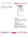
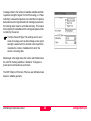
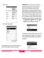
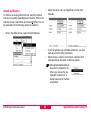
Leica SR20 Getting Started Guide Version 1.0 English Leica SR20 Symbols Used in This Manual Congratulations on your purchase of a new Leica SR20. Symbols used in this manual have the following meanings: WARNING: Indicates a potentially hazardous situation or an To use the equipment in the permitted manner, please refer to the detailed safety instructions in the User Manual. ) © 2004 Leica Geosystems AG Heerbrugg, ® All rights reserved. unintended use which, if not avoided, could result in death or serious injury. Important paragraphs which must be adhered to in practice as they enable the product to be used in a technically correct and efficient manner Tip: Indicates useful information that may help you execute a task. Remember: These paragraphs contain summarized information or important tips. SR20 Getting Started Guide-1.0.0en 2 View of chapters SR20 Getting Started Guide-1.0.0en 1. Equipment Setup .................................................................6 2. Surveying..............................................................................9 3. Configuration Sets.............................................................18 4. Applications & Other Functions .......................................27 5. Transferring Data from the SR20......................................47 6. Using Leica Geo Office......................................................52 3 View of chapters Table of Contents 1. Equipment Setup ........................................... 6 3. Configuration Sets ...................................... 18 Static Setup on a Tripod ......................................... 6 Kinematic Setup on a Pole ..................................... 7 Stakeout using the Handheld ................................. 7 Getting Started with the Receiver ........................... 8 Create & Modify a Configuration Set .................... 19 Configuration Options ........................................... 19 GPS ...................................................................19 Data Collection ...................................................22 Interfaces ............................................................24 Units and Formats ...............................................26 2. Surveying ....................................................... 9 Introduction to the Main Menu ................................ 9 4. Applications & Other Functions ................ 27 Accuracy Indicator ...............................................9 Stop and Go Indicators ........................................9 Satellite Indicator .................................................9 Differential Corrections ........................................9 Memory Card Status ..........................................10 Battery and Time Indicators ...............................10 Cultivated Field Control ........................................ 27 Introduction ........................................................27 Setup ..................................................................27 Using the Program .............................................29 1-Step Transformations ........................................ 32 File Conversion ..................................................... 35 Start a New Survey .............................................. 11 Create a New Job ................................................. 12 Create a New Codelist ......................................... 12 Data Collection ..................................................... 13 To Import ............................................................35 To Export ............................................................37 Coordinate Geometry (COGO) ............................. 38 Offsets .................................................................. 42 Point Collection ..................................................13 Line/Area Collection ............................................14 Azimuth and Distance ........................................43 Double Azimuth or Double Distance. ..................44 Reverse Azimuth and Distance. ..........................44 Stakeout ............................................................... 16 Set Stakeout Point .............................................16 SR20 Getting Started Guide-1.0.0en Key Codes ............................................................ 45 4 Table of Contents 5. Transferring Data from the SR20 ............... 47 Using Compact Flash Card Adapter ..................... 47 Transfer Data via a Serial Cable .......................... 48 6. Using Leica Geo Office ............................... 52 LGO Data Processing .......................................... 52 LGO Overview ...................................................... 52 Creating a Project ................................................. 53 Importing Data ...................................................... 54 Assigning the Data to a Project ............................ 55 GPS Processing ................................................... 56 Export ................................................................... 57 SR20 Getting Started Guide-1.0.0en 5 Table of Contents 1. Equipment Setup The following sketch illustrates setup on a tripod: This chapter of the Getting Started Guide illustrates how to setup the SR20 hardware. The SR20 hardware can be setup in several different configurations. It can be setup on a tripod with an external antenna for static data collection. The SR20 can be setup on a pole with an external antenna for kinematic data collection. The SR20 can also be used as a handheld receiver for stake-out or data collection. a b c Static Setup on a Tripod d Setup on a tripod requires the following parts: a External Antenna b Tripod Setup (including tribrach and carrier) c SR20 GPS Receiver d SR20 Battery e SR20 Pole Bracket f Antenna Cable f e SR20_001 SR20 Getting Started Guide-1.0.0en 6 Equipment Setup Kinematic Setup on a Pole Stakeout using the Handheld Kinematic setup on a pole requires the following parts: a External Antenna b Pole c SR20 Pole Bracket d Antenna Cable e SR20 Battery f SR20 GPS Receiver Handheld setup requires: a SR20 Battery b SR20 GPS Receiver The following sketch illustrates handheld setup: The following sketch illustrates setup on a pole: a a b b d SR20_003 e c f SR20_002 SR20 Getting Started Guide-1.0.0en 7 Equipment Setup Getting Started with the Receiver Once the equipment is setup, you are ready to begin using your SR20. Please follow the next chapters closely for instructions on how to operate the SR20. Other resources available for information on the SR20 are the SR20 Users Manual and the Leica Geo Office online help system. SR20 Getting Started Guide-1.0.0en 8 Equipment Setup 2. Surveying Stop and Go Indicators Introduction to the Main Menu To turn on your SR20, press the button in the bottom left hand corner of the keypad. The unit will beep followed by the Leica splash screen and then the main menu. When a static position is located, such as a point or a node (in a line or area), the stop and go indicator is displayed as a tripod. Once the icon returns to the walkingman, the user can proceed to the next collection point. The Icon area is displayed to provide the user with current information about the GPS and hardware. Satellite Indicator Accuracy Indicator Stop & Go Indicators Satellite Indicator The satellite indicator provides text based information including the satellite tracking angle, the number of satellites visible (according to the almanac) and the number of satellites currently tracked. (Satellites Tracked / Satellites Visible) Battery & Time Indicators Differential Corrections Memory Card Status Differential Corrections When differential corrections are received and interpreted, the differential icon appears. If the correction is lost after 1/3 of the selected age, an exclamation point will appear in the lower left hand corner of the window. If it is still absent after 2/3 of the selected age, an additional exclamation mark will appear. If corrections are lost beyond the selected age, a third exclamation will appear and the icon will then disappear. Accuracy Indicator The accuracy indicator is displayed once a solution is calculated. An open sphere indicates an autonomous position has been determined, while the bullseye target indicates a DGPS solution. Additionally, information provided in the text include horizontal and vertical qualities, as well as PDOP. SR20 Getting Started Guide-1.0.0en 9 Surveying Memory Card Status • The memory card status icon provides a graphical representation of the percentage of the compact flash used. • Battery and Time Indicators • • The battery and time indicators provide information about the current status of the onboard battery and the current time obtained by satellites. • Because the battery indicator is based on a microprocessor in the Lithium Ion battery, only the onboard battery status can be provided in percentages. • Because the Leica SR20 does not rely on internal batteries for clock function, time is only displayed when 1 or more satellites are tracked. • 1 Survey - guides users through job creation and data collection. 2 Data Management – provides users with the ability to view collected data in tabular format. 3 Stakeout – serves as a navigation tool to locate points. 4 Applications – provides the ability to perform Cultivated Field Control, 1-step transformations, File Conversion and Coordinate Geometry. 5 Setup – allows users to define the configuration that will be used for data collection (e.g. Post Process, Kinematic). There are five menu options available to the user from the Main Menu: SR20 Getting Started Guide-1.0.0en 10 Surveying ) Start a New Survey Select 1 Survey from the Main Menu. • For further definition of the default configurations available and how to create a customized configuration refer to chapter "3. Configuration Sets". Select the Antenna Type that you will be using. After selecting 1 Survey from the main menu, the user is presented with the Quick Start interface. This screen allows the user to quickly set up the SR20 parameters for the survey. • Select one of the default Configuration sets. SR20 Getting Started Guide-1.0.0en 11 Surveying Create a New Job Create a New Codelist • • Create a name for the new job. Press the Menu button, select 4 Job and then select 1 New. The Job Management screen will appear. • • • • • • Enter the Job Name and select a coordinate system (default is WGS84). Select geoid and CSCS files if necessary. Refer to LGO online help for further material regarding coordinate systems, geoids & CSCS file creation. Press Escape and Save the new job. This will bring you back to the Quick Start Interface. Select a codelist to attach to your job. There are two options. The user may either select the default codelist, "Generic", which contains three codes - Point, Line and Area - or the user may create their own codelist. SR20 Getting Started Guide-1.0.0en • • • 12 To create a codelist from within the Quick Start Interface, press Menu and select 5 Codelist. Codelist Manager will display. Press Menu and select 1 New. Enter Name for new codelist. Press Escape and Save new codelist. To add a code, press the Menu button, select 5 Codelist, then select 2 Codes. In the New Code interface, select 1 New Code. Enter the new Name and Type. Add a description if necessary. Press Escape and Save the new code. Create additional codes if necessary. Otherwise, return to the Quick Start Interface. Surveying • After setting all Job parameters, select Apply. Data Collection Congratulations, you have successfully set all parameters for the SR20 and are ready to proceed with data collection. Point Collection • • • • Accept the default point name or enter a user defined name by selecting the Point Name input box and pressing Enter. Enter Antenna Height. Select the proper Point Code from the choicelist. Select Occupy to start the data collection. ) SR20 Getting Started Guide-1.0.0en 13 While a point is being occupied, information regarding GDOP, time of occupation and percent completed is supplied. Surveying • When you are through capturing a point, select Stop & Store. The point will be stored and you will be ready to collect your next point. SR20 Getting Started Guide-1.0.0en Line/Area Collection • • • The SR20 also has the ability to collect Lines and Areas. To select the type of feature you would like to collect, Press Menu and select 2 Code Type. Select line or area. 14 Surveying If you selected line or area as the code type, you’ll notice a change in the interface, in the form of two additional buttons. To the left of the Occupy button is the mode button. The user has the ability to capture data for line and area types using either Point or Stream Mode. Point mode is the manual collection of nodes or “vertices.” Stream Mode is the automatic collection of nodes (i.e. vertices) based on a distance or time setting. • • • • To collect lines or areas using Point mode, press menu and select 2 Point. To collect lines or areas using Stream mode, press menu and select 3 Stream. To collect data, select Occupy. When occupation is complete select Stop and then select End Line or End Area depending on which code type has been specified. To the right of the Occupy button is the End button. When Occupy is selected to begin data collection, it is replaced by the Stop button and the End button becomes active. The Stop button merely pauses data collection, in the event of nesting another feature, allowing you to reoccupy if you are not through collecting the feature. While the End button ceases data collection. In the case of area collection, End will close the polygon. SR20 Getting Started Guide-1.0.0en 15 Surveying ) At anytime during data collection the user has the ability to toggle between the Occupation interface and the GPS Satellite View by pressing the Page button on the keypad. Stakeout Stakeout allows the user to navigate to a given feature in the field. The Stakeout interface provides a point management view, map view, a compass arrow and information regarding distance from the selected stakeout point. Set Stakeout Point • • • SR20 Getting Started Guide-1.0.0en 16 Select 3 Stakeout from the Main Menu. Press Menu and select 1 Point Management. Press Enter to select a point. Surveying • The stakeout interface will appear, the point you selected for stakeout will be selected and the information regarding distance and direction from current location will be displayed. Using this information, the user is able to navigate to the stakeout location. SR20 Getting Started Guide-1.0.0en 17 Surveying 3. Configuration Sets Several default configuration sets are provided with the SR20 to facilitate the commencement of data collection. New configurations can be created and default configurations can be modified, but any modifications upon a default must be saved as a different name. Below is an explanation of four commonly used default configuration sets provided with the SR20: • STATIC refers to post processing static phase. This type of data collection is used for high accuracy, single point occupations, which require that each ambiguity resolution is a separate calculation. For this type of data collection, a status indicator provides user feedback regarding the length of time necessary to occupy a data point in order to provide a high level of confidence that the ambiguity of the point will be resolved. SR20 Getting Started Guide-1.0.0en • KINEMATIC is also a form of phase data collection. Ambiguities are resolved on an initial static point and then these corrections are applied to all collected data within an unbroken kinematic chain. If, at any time, the number of available satellites drops below 4 the chain will be broken and the user will be required to initialize upon another static point. • SBAS, Satellite Based Augmentation System, is a free real-time or differential correction technique. WAAS is the correction available in North America and EGNOS is the European equivalent. • RTREF is utilizing the SR20 as a reference station. This configuration will send a real-time message out of a port of the SR20 receiver. The following sections explain how to create new configurations, modify existing configurations and step through the configuration setup of these four methods to better understand their differences. 18 Configuration Sets Create & Modify a Configuration Set Configuration Options • From the SR20 Main Menu, Select 5 Setup, 1 Config Sets, press the Menu button (located at the top of the SR20 keypad) and select 1 New. To gain a better understanding of these configuration options, we will now explore the settings available in each of the four Setup categories. • Enter a user-defined name for the new configuration. GPS • To modify this configuration press the Enter button. You will be prompted with the following interface: ) There are four categories of available configuration options – GPS, Data Collection, Interfaces and Units & Formats. Examples of options that can be modified include, antenna type, quality control, PDOP filter, and offset device parameters. SR20 Getting Started Guide-1.0.0en First we will examine GPS setup options: The Tracking subgroup refers to settings that pertain to the quality of satellite strength based on satellite geometry and field position. Tracking settings for the SR20 include Coverage, Mask Angle and DOP Filter. These settings allow the user to set a minimum threshold, in terms of the quality of the signal received by the sensor, in order for a point’s location to be saved. 19 Configuration Sets Coverage refers to the number of available satellites and their respective strength of signal. For Post Processing (i.e. Phase collection), because the objective is to collect the most precise data and ensure the highest likelihood of ambiguity resolution, the tracking option must be set to Max Accuracy. This means that only data from satellites with the strongest signals will be recorded by the sensor. ) The Max Trak and Hyper Trak settings are for use in areas of coverage, such as dense foliage, where signal strength is weaker and it is deemed more important to maximize the number of satellites from which the sensor is receiving data. Mask Angle is the angle above the horizon which determines the cutoff for tracking satellites. A default of 10 degrees is preset and recommended as a minimum. The DOP, Dilution of Precision, Filter is a user definable mask based on satellite geometry. SR20 Getting Started Guide-1.0.0en 20 Configuration Sets The Minimum Satellites control allows the user to define how many satellites must be tracked to calculate a position. The default setting is 4 satellites, because a minimum of 4 satellites is necessary to calculate a three dimensional position. The Antenna Type setting defines the phase center offset of the antenna. These include the AT501 Pole and AX1201 Pole (external antenna on a pole), the AT501 Tripod and AX1201 Tripod (external antenna with Leica height hook offset), and the SR20 Internal antenna. The Baseline setting approximates the baseline length between GPS receivers. This setting determines the suggested time required to occupy a point for kinematic and static data collection. ) SR20 Getting Started Guide-1.0.0en 21 The Leica SR20 automatically senses when an antenna has been plugged in or unplugged. The unit opens and resets the antenna configuration accordingly. Configuration Sets The Logging screen contains controls to store raw pseudorange data for post-processing, static and moving observations as well as set the positional update rate for the receiver. The positional update rate of the SR20 is one update per second. for kinematic data and a 5 second rate for static data collection. These settings are of no consequence if you are collecting data via the SBAS configuration – however, if you lose SBAS (real-time correction) it is good practice to have these settings checked, as backup to ensure that you can post process the data using Leica Geo Office Software and prevent against loss of data. Data Collection The Data Collection subgroup is where quality settings are defined for both automatic collection and notification alarms. ) Data collected without enabling the logging CANNOT be post processed for corrections. If you are collecting data using the STATIC configuration select the Log Static Observations check box. If you are collecting data using the KINEMATIC configuration select the Log Static Observations and Log Moving Observations check box. In both circumstances the Observable Logging Rate should also be set. This rate controls both moving and static logging rates, it is recommended that 1 second be used when SR20 Getting Started Guide-1.0.0en 22 Configuration Sets The Quality Control controls are subdivided into Point Quality (also applicable for linear node collection) and Line/ Area streaming. • Point Quality • • Quality – The occupation will be stopped once the Quality defined (e.g. Horizontal < 1m) is achieved Positions – The occupation will be stopped once the number of required positions has been collected. Stop and Go – Set when collecting static phase data. Occupation will be stopped once the time period for data collection has been met. This number is determined based on distance from the reference. ) Point Quality is defined by Horizontal, Vertical, Horizontal & Vertical, or None. ) If only Horizontal or Vertical quality is chosen, the other will be disabled. Point Autostop has four different settings: • None – Occupation is manually controlled (started and stopped) by the user. SR20 Getting Started Guide-1.0.0en Positions will NOT be stored unless the required quality has been achieved. CQ Warning (Coordinate Quality): Even if Point Autostop is set to none, a notification alarm can be set to alert the user that the defined quality has been exceeded. To do so this option should be checked. Line Quality The Line Quality setting allows the user to define the horizontal quality tolerance for linear streaming. The line quality can be used to filter or notify the user of positions that have exceeded the quality tolerance. Line quality is then displayed during data collection when the streaming option is selected. 23 Configuration Sets Interfaces The Interfaces subgroup controls how external devices interact with the SR20. The external devices that can interface with the SR20 include Real-Time (e.g. SBAS), Offset Devices, NMEA and ASCII input. ) Real-Time RTCM messages are disabled on the SR20 and require a key code to become activated. Please contact your local Leica representative for more information. The SR20 includes several default devices available for RealTime Interface: • RTB – CSI Real-Time Coast Guard Beacon • RS232 – Open Standard for 3rd party devices • GSM - Global System for Mobile Communications • Modem Devices To view or edit the properties of the device being used, press the Menu button and select 2 Device Properties. Real-Time or Differential Correction involves the GPS receiver receiving correction data to achieve higher accuracy. The SR20 supports two combined message formats of the RTCM standard (Radio Technical Commission for Maritime services). The combined message formats are (9,2) / (1,2) / (18,19) and (20,21). SR20 Getting Started Guide-1.0.0en 24 Configuration Sets The SBAS default configuration, is Real-Time Correction. The settings for the SBAS Real-Time interface: To add an offset device setup: • Select 5 Setup, 1 Config Sets • Select the configuration you are working with and press Enter • Select Interfaces, then select Offset Devices • Place a check mark in the box next to Enabled • Select the Offset Device you are using and then select the Port through which you plan to be sending data to the SR20 (port 1 for direct connection to the SR20 or WoRCs1/WoRCS2 for wireless transfer) Offset Devices are used to collect points that cannot be easily or accurately accessed for direct GPS occupation. In this case, the user has the option of calculating the location of that point based on a given offset. The SR20 offers four point offset collection methods and works with most laser range finders. Leica’s Laser Rangefinder can be interfaced with the SR20 either directly through serial port 1 or with the use of the WoRCS belt using ports 1 or 2. The latter method allows data to be transmitted to the SR20 cable free. SR20 Getting Started Guide-1.0.0en 25 Configuration Sets Units and Formats Units and Formats allow the SR20 to be entered and displayed according to user specifications. Formats includes settings for: • Local Time Zones • Date Format • Coordinate Format ) Actual time will be read from the GPS satellites. Units of Measure includes a list of types of measurements from which the user may define preferred units. SR20 Getting Started Guide-1.0.0en 26 Configuration Sets 4. Applications & Other Functions This chapter outlines several applications and functions that are built into the SR20 firmware to facilitate complex data collection. Applications included with the SR20 include, Cultivated Field Control, 1-step transformations, database conversion and coordinate geometry. Additional functionality included with the SR20 to facilitate data collection include offsets and real-time key codes. Setup With the possibility to use a mask file, the application is open to a variety of output into different ASCII file interfaces. The mask file *.MAS is a simple ASCII text file to be opened with any text editor on a PC. Cultivated Field Control Introduction Cultivated Field Control (CFC) is an SR20 application aimed at providing an accurate record of crop quantities and tolerences. A user can collect and select a polygon, and calculate the area with an error estimate corresponding to a userdefined tolerance. Additional functionality also allows the user to subtract areas within the external area, and save the subsequent data to a text log file that can be exported to a personal computer. CFC is an additional application that requires a keycode file. To purchase the application and receive a keycode, please contact your local Leica representative. SR20 Getting Started Guide-1.0.0en • • • • 27 The @LEICA CFC MASK@ is the identifier for any mask file. The @@@ is the identifier for the end of the mask file. The lines between both identifiers are restricted to an amount of 15, each line with 80 Characters maximum. The @00@ until @99@ are place holders for the numerical values or code/ attribute info. This gives full and easy flexibility to create different output masks for any ASCII type. Applications & Other Functions • A sample Leica.mas file (right) is provided and can be edited to the needs of the user. All identifiers are listed below: Case 00: // new line Case 01: // @ Case 05: // Active Job-name Case 06: // Current Date Case 07: // Current Time Case 09: // Number of excluded areas Case 10: // Area Size [m²] Case 11: // Area Accuracy [m²] Case 12: // Perimeter [m] Case 13: // EC Tolerance [m²] Case 14: // EC Tolerance [% ] Case 15: // Area Id Case 16: // lower Boundary [m²]/ upper boundary [m²] Case 17: // lower Boundary [m²] Case 18: // upper boundary [m²] Case 20: // Area Code Case 21: // Attribute ... Case 40: // Area Attribute Value 1-20 Case 41: // Area Code Note Case 60: // point id SR20 Getting Started Guide-1.0.0en Case 61: // north(*) Case 62: // east(*) Case 63: // height [m] Case 64: // height type (Orthometric/Ellipsoidal) Case 65: // geoid height [m] Case 66: // Point Date Case 67: // Point Time Case 71: // CQ North [m] Case 72: // CQ East [m] Case 73: // CQ Hgt [m] Case 74: // CQ Pos [m] Case 75: // CQ 3D [m] Case 80: // iterator, starts with 1 for first point of each area point block. Case 99: // end of point block, only necessary to divide point block from footer lines. (*) north and east are displayed with 3 digits in meter [m]. If no coordinate system definition is available it is displayed as 360 degree decimal with 9 digits. The *.MAS file should be placed in the Data/Apps/CFC directory of the SR20 compact flash. A LOG file name defined by the user will be output to this directory as well. 28 Applications & Other Functions Using the Program Cultivated Field Control can be found under the Application selection in the main menu. If a job is not yet opened, the workflow will request that you open or create a job. Once in the CFC main screen, the user will be required to: • Select the Area for calculation (Mandatory) • Select any internal areas to be subtracted from the calculation (Optional) • Select a mask file (Mandatory to save a log file) • Provide the name of the Log file to be saved. • Select a tolerance or error limit for the calculation. To select a feature, make the feature box the focus of the cursor, and press the menu button. Areas can also be calculated from this menu. The main Cultivated Field Control menu provides the ability to: • Select a feature to calculate • Select interior features to exclude from the calculations • Choose a mask file to properly format the output file • Enter the name of the output or “LOG” file • Enter the tolerance or error of calculation SR20 Getting Started Guide-1.0.0en 29 Applications & Other Functions An area can be selected from the table by highlighting the area and pressing enter. An area may also be selected by copying it to the clipboard from a map or table display in Data Management or Navigation. Areas internal to the main feature, or parent area, can be excluded from the calculation. The selection process is identical to selecting a main feature, but it is possible to select multiple features to be excluded. The 09 command will not only provide the number of features excluded, but will provide detail about each feature. ) The application does not verify that the area is within the parent object. Be careful when calculating! Available mask files will appear in the mask selection box. ) • • SR20 Getting Started Guide-1.0.0en 30 A mask file is necessary to create an output file! Enter the name of the Log file to be saved (In the LOG directory) Select a Tolerance or limit of error. Applications & Other Functions To Calculate, press Menu and select Calculate. A brief narrative of the calculation will appear on screen. To save your data, and/or get a view of the generated log file, press enter and select one of two choices. The log file will now be available from the flash card, directly. SR20 Getting Started Guide-1.0.0en 31 Applications & Other Functions To create a transformation, follow these instructions: 1-Step Transformations The SR20 Transformation application is used to transform coordinates to a new coordinate system. The 1-Step Transformation is available for you to convert points from Latitude, Longitude, and height to a local system. This will allow you to work in a local coordinate system in the field. In order to create a transformation, you will need to locate points with GPS (latitude, longitude, height) and also have the local coordinate values (Northing, Easting, Elevation) for these points. A transformation can be done using both vertical and horizontal position, horizontal only or vertical only. • • Create a job in the SR20 and collect the points that are going to be used in the transformation. See chapter "2. Surveying" of this guide for further instruction on how to create a job and collect points. Select 4 Applications from the Main Menu. Then select 2 Transformation (1-Step). • Name the New Coordinate System that will be created from the transformation calculations. Type in the name of the new coordinate system in the New Coord Sys dialog box. Then select Apply. 32 Applications & Other Functions It is recommended that a minimum of 4 points be used for both horizontal and vertical control, in order to obtain optimum results, when performing a transformation. Any number of points may be used, but the residual values will not be as significant. SR20 Getting Started Guide-1.0.0en • Select the point pairs that you will use for the transformation. ) • • Use the Match option to select whether you will match each pair by; Position, Height, Position and Height, or exclude. Make the appropriate setting for each pair that you match. • Once you have the appropriate setting selected, scroll to the Store pt pair button and select Enter. A dialog box will 33 Applications & Other Functions The WGS84 point is the point that you have stored with GPS. The Local point is the point that you have entered in or uploaded to the GPS receiver. Select these points from the combo boxes. Make sure to match the WGS84 with the corresponding Local point. If you do not have the Local point in the current job, you can enter the local point here. • Under Local Pt ID select New. Enter a new point number and coordinate values for this point. SR20 Getting Started Guide-1.0.0en appear to notify you that the point pair was stored. Repeat this procedure for all pairs used in the transformation. To compute the transformation: • Select Menu and 3 Perform Trans. SR20 Getting Started Guide-1.0.0en To see the residuals of the transformation: • Select Menu and 1 Results. • 34 Select Menu, 3 Save Coord Sys to save the computed transformation and create a New Coordinate System. Applications & Other Functions ) This new coordinate system will be saved and automatically attached to the current job. File Conversion The File Conversion application enables the user to Import ASCII and GSI files into a job or Export a job as ASCII or GSI. This application is accessed by selecting 4 Applications from the Main Menu and then 3 File Conversion. To Import • Select Import ASCII ) SR20 Getting Started Guide-1.0.0en 35 Files to be imported into a job must be placed in the Data directory on the Compact Flash card. Applications & Other Functions If a job is open, the following Import interface will appear: • • • • Once in the Import interface select the Import File Type. Choose the From File - the file to be imported into the current job. Select the Coordinate System of the points in the file. Select the Coordinate Units of the points in the file test.txt If a job is not open, you will be prompted to open one before proceeding with the import process. 3 • • • SR20 Getting Started Guide-1.0.0en 36 Select the Height Type - Ellipsoid or Orthometric. Select the Delimiter - a character marking the beginning or end of a unit of data. Finally select the field position that contains the Point Number, Northing, Easting and Elevation. Applications & Other Functions To Export • Select 4 Applications from the Main Menu, 3 File Conversion and 2 Export ASCII. • • Select the Export File Type. Select the Format File. This is a user defined file, created with the assistance of Format Manager office software, which specifies what data (e.g. Northing, Easting, Code,) are to be passed along in the export file. This file should be created in Format Manager and placed in the Convert directory of the CF card. Enter a name (with extension) for the exported file in the To File input box. • SR20 Getting Started Guide-1.0.0en • Select Export. ) 37 The exported file is placed in the Data directory on the Compact Flash card. Applications & Other Functions • Coordinate Geometry (COGO) The COGO function is an application used for coordinate geometry calculations. From the Main Menu select 4 Applications, then select 4 COGO. There are three functions under the COGO application: Inverse, Traverse and Intersection. • • Select a Point or Node (point on a line or area) from the first combo box. Select the point or node for which you want to calculate the inverse. To compute the Inverse, arrow down and select Calculate. The azimuth, distance and height difference are displayed in the box below the Calculate button. You can also display the bearing by selecting Menu and Bearing. INVERSE: This command is used to calculate the azimuth (or bearing), distance, and delta height between any two points in a job. SR20 Getting Started Guide-1.0.0en TRAVERSE: This command is used to compute new positions computed from angle and distance computations. An initial point is required as well as angle and distance information to the next point. • From the Main Menu select 4 Applications, 4 COGO and then select 2 Traverse. • • In the Traverse screen, select your starting point and enter in the data to compute the next point in the traverse. Enter the azimuth, distance, delta height and offset. 38 Applications & Other Functions • Select Traverse. • Enter the point name and code. INTERSECTION: This command is used to compute the intersection between two lines. This can be done three different ways; Azimuth-Distance, Azimuth-Azimuth, Distance-Distance. The Azimuth-Azimuth method is used when two points and two bearings are known. The Azimuth Distance method is used when one azimuth is known and one distance is known. The Distance-Distance method is used when only distances are known. All three of these methods will compute intersections based on the information entered. • Select 4 Applications, 4 COGO and then select 3 Intersection to access the Intersection computation. The following screen appears, listing the three types of intersection calculations that are available. You can compute an intersection with an azimuth and distance, two azimuths, or two distances. You will then be sent back to the traverse screen where you can enter the information to traverse to the next point. SR20 Getting Started Guide-1.0.0en 39 Applications & Other Functions To compute an intersection with an azimuth and distance: • Select a point and an azimuth. You can also define a parallel offset. • Select your second point and the distance from that point. • Press Menu and Calculate to determine the intersection,. SR20 Getting Started Guide-1.0.0en To compute an intersection with two azimuths: • Select your first point and the azimuth. • Select the second point and the azimuth and parallel offset. ) You can also enter in a parallel offset. • Press the Menu button and Calculate to compute the intersection and to save the new point. 40 Applications & Other Functions To compute an intersection with two distances: • Select the first point and the distance. • Select the second point and distance. • To compute, select Menu and Calculate. • You will then be prompted to save the point. SR20 Getting Started Guide-1.0.0en 41 Applications & Other Functions Aux “A” Because two solutions exist for a double distance intersections, the user must tell the software on what side of point A-B the offset point lies. + O/S Pt Azimuth Distance Aux “A” Aux “B” 0o 110 o 22 ) ” When collecting a point offset, it is important to input the offset data before occupying the auxiliary point. Azimuth Distance: Enter Azimuth, Distance and Delta Height before occupying the point. Azimuth Azimuth: Enter Azimuth and Delta Ht for 1st position from Aux Pt. A; then repeat for PT B. Distance Distance: Enter Distance and Delta Ht for 1st position from Aux Pt A; repeat for position B and choose the solution method (i.e. Left or Right) 00 0’ o3 5 12 5m 3 Offsets + Azimuth - Azimuth + m 35 O/S Pt O/S Pt (Left Solution) 25 m Aux “A” Aux “B” R (Right Solution) Distance Distance SR20 Getting Started Guide-1.0.0en 42 Applications & Other Functions Azimuth and Distance • Collect the value with your rangefinder or enter them manually. • If your rangefinder only calculates a distance, you must manually enter the other parameters. Select Occupy, similar to normal point collection. Both manual and auto-stop work in offset occupation. To collect a point using offset methods, select the desired code as you would for a standard point collection. When in the collection screen, select Menu and choose 2 Offset. You will be presented with the following options for collection: • Once in the Offset screen, select Azimuth Distance. • ) SR20 Getting Started Guide-1.0.0en 43 Although a default Auxiliary or base point is created for the offset, you can use the geoclipboard to select from a stored base point for multiple occupations. Applications & Other Functions Double Azimuth or Double Distance. Reverse Azimuth and Distance. Collecting an offset using double Azimuth or Double distance methods requires collecting both range and occupation information from two locations. • Populate the “A” fields manually or with a range finder, then occupy the point. • After the “A” occupation has taken place, the “A” fields are no longer editable. • Populate the “B” fields, then take the “B” occupation. Escaping will allow for points to be re-occupied, however it is not possible to keep the “B” collection and re-occupy “A”. The backward, or reverse Azimuth and Distance method allows you to calculate your position, by sighting a reference point of known origin. A known node or point feature must be copied to the GeoClipboard. The node or point can be copied to the Geo-Clipboard by map or table in Data Management or Navigation. The known feature is automatically selected from the GeoClipboard in the offset screen. No Occupation is necessary. ) SR20 Getting Started Guide-1.0.0en 44 By Calculating the Back. Azimuth Dist. Offset without populating the fields (i.e. zero), it is possible to create new features with a shared topology to the parent “pasted” node. This topology is maintained when the parent node is post-processed or deleted. Applications & Other Functions Key Codes • If you have the menu in hidden mode, select ESC to display the full Main Menu. Then select 5 Setup. • Select 2 Hardware Management. The same GPS hardware can be used as a GS20 or SR20. To switch the GPS receiver from the GS20 firmware to the SR20 firmware you will need to enter a key code. Contact your local Leica Geosystems representative to order this key code. The SR20 does not come standard with the ability to receive real-time data. This functionality must also be activated via a key code. ) The WAAS/EGNOS option does come standard on the SR20. To switch between GS20 to SR20 or SR20 to GS20, follow these instructions: SR20 Getting Started Guide-1.0.0en 45 Applications & Other Functions • Scroll down to sensor type and press Enter. • The system will then shut down. When you turn the receiver back on, it will come up as the new type of receiver. Here you can choose the type of receiver you want to switch to, SR20 or GS20 from the combo box. • • Select Apply to make this change. Enter your key code. SR20 Getting Started Guide-1.0.0en 46 Applications & Other Functions 5. Transferring Data from the SR20 There are two methods for transferring data to and from the GPS sensor: • Directly from the Compact Flash Card. • In Leica Geo Office using a serial cable. SR20 Getting Started Guide-1.0.0en Using Compact Flash Card Adapter Data can be transferred from the SR20’s compact flash card directly to Leica Geo Office with the use of a card reader. To transfer data using this method simply shut down the SR20, remove the compact flash card, place the card in the compact flash card adapter and place the adapter into your PC. The card reader is recognized as an additional drive and as such can be accessed through Leica Geo Office or Windows Explorer. Proceed to chapter "6. Using Leica Geo Office" for instructions on importing SR20 data into Leica Geo Office. 47 Transferring Data from the SR20 Transfer Data via a Serial Cable • The Data Exchange Manager interface will appear. • Right click on the white space and select Settings. Alternatively, data can be retrieved from the SR20 through LGO via a serial cable connection between the sensor and the PC. • • Open Leica Geo Office. Select Data Exchange Manager from the Tools Pull down Menu. SR20 Getting Started Guide-1.0.0en 48 Transferring Data from the SR20 • Select the General tab. Select GPS 500 for the PC-CF Card setting and the Create field Objects for: setting. • • • Select the COM Settings tab in the Settings dialog Select COM 1 for the Port setting. Select GPS500 for the Instrument setting. ) SR20 Getting Started Guide-1.0.0en 49 GPS500 is selected because the SR20 uses the GPS500 data structure. Transferring Data from the SR20 • • Connect the serial cable to the SR20 and PC. On the SR20, select 8 Utilities, 3 Sensor Transfer. Select 1 for the Port setting and then select Apply. SR20 Getting Started Guide-1.0.0en • • • 50 In LGO, double click on Serial Ports in the left hand contents window of Data Exchange Manager. Double click COM1. Expand the PC Card folder, expand the Objects folder, expand the Jobs folder. Transferring Data from the SR20 • • Select the job you would like to transfer to your PC. Right click on the job you would like to transfer and select Copy. • • In the right hand Contents window, navigate to the folder where you would like the job to reside. Paste the contents. After your data has downloaded, it is ready for import into LGO. SR20 Getting Started Guide-1.0.0en 51 Transferring Data from the SR20 6. Using Leica Geo Office LGO Data Processing LGO Overview The Leica Geo Office (LGO) is the processing software that should be used with your SR20 data. To install this software insert the LGO CD in your computer and you will be prompted for installation instructions. The LGO software is powerful software capable of numerous applications. For the purpose of this manual we will outline how to process specifically SR20 static and kinematic data. For further information on LGO please see the detailed Online Help section within the LGO software. In order to process static and kinematic data, you will need a key lock that will be connected on the parallel port of your computer. This key lock will activate the ability to process only SR20 static and kinematic data. The LGO software is capable of processing data from many Leica receivers including System 1200 GPS and TPS and digital level data. In order to utilize these options you will need to purchase the appropriate key lock to activate these options. Please see your local Leica representative for more information. SR20 Getting Started Guide-1.0.0en 52 Using Leica Geo Office When starting the program you will see the above menu. You can access functions within this program via the pull-down menus at the top of the screen, via the Icons in the top tool bar or along the left hand side of the screen. On the left hand side of the screen there are two tabs, the Management tab and the Tools tab. Under each of these tabs are a number of icons that shortcut the user to different application within the program. Creating a Project In order to import data, you need to create a project to import the data into. • Select File and New Project. You will then see this dialog box: In this dialog box enter a Project Name and location to save your project. For further information on other selections in this dialog box, please refer to the LGO Online Help menu. Select OK to create this project. SR20 Getting Started Guide-1.0.0en 53 Using Leica Geo Office Importing Data • Select the Import button. • Repeat this procedure for all raw data files. To import your SR20 data into LGO use the Import option from the Import Pull-Down menu. • Select the Raw Data Option. In the Import menu select the SR20 Raw Data file that was collected in the field. You can read this directly from the CF card. If you do not have a CF reader, refer to Section 5 of this manual for instructions on downloading via cable. Select File of type to be GPS500 raw data. SR20 Getting Started Guide-1.0.0en 54 Using Leica Geo Office Assigning the Data to a Project The data must be assigned to a project in order to process the data. For detailed information on all the options with the Assign window refer to the LGO Online Help. • Highlight the project that you want to Assign the data into. • Select Assign. • Select Close. Select the GPS-Proc Tab to continue on to the data processing screen. The View/Edit tab will be displayed. The graphical representation of your point can be seen from this screen. SR20 Getting Started Guide-1.0.0en ) 55 To configure the tabs displayed at the bottom of the LGO screen, right click and check the tabs you wish to have displayed. Using Leica Geo Office GPS Processing The GPS Processing screen allows you to post-process your static and kinematic data. • • • In order to fix a point as a known value, right click on the point number and select Edit Point. Set the Point Class as Control, this will allow you to edit the point and put in the true value for that point. To begin processing, select a point as reference and a point as rover. To do this by right clicking on the grey time bar and choose either Reference or Rover. ) You must have common time between Reference and Rover in order to process. To start the Processing, right click and select Process. SR20 Getting Started Guide-1.0.0en 56 Using Leica Geo Office After computing a baseline you will be taken to the Results tab. Here you can look at the results of the computation. For further information on this refer to the LGO Online Help menu. To store a baseline right click on the point number and Select Store. • Export To export your results to a final format utilize the Export function. Select Export from the pull-down menu. Choose RINEX, ASCII, or GIS/CAD. For further details on these refer to the LGO Online Help menu. Repeat this procedure for all baselines to be processed. SR20 Getting Started Guide-1.0.0en 57 Using Leica Geo Office Leica Geosystems AG, Heerbrugg, Switzerland, has been certified as being equipped with a quality system which meets the International Standards of Quality Management and Quality Systems (ISO standard 9001) and Environmental Management Systems (ISO standard 14001). 742211-1.0.0en Printed in Switzerland - Copyright Leica Geosystems AG, Heerbrugg, Switzerland 2004 Original text Total Quality ManagementOur commitment to total customer satisfaction. Ask your local Leica dealer for more information about our TQM program. Leica Geosystems AG CH-9435 Heerbrugg (Switzerland) Phone +41 71 727 31 31 Fax +41 71 727 46 73 www.leica-geosystems.com