1
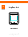
Display-Unit
User Manual
User Manual_Display Unit V1.0_FI
CE, Rohs, ISO9001:2008
Subject to change without notice!
Contents
1.Safety instructions and waiver of liability .................................................................................................
2
1.1 Safety Instructions
1.2 Liability Exclusion
2.Pruduct Overview................................................................................................................................................
3
2.1 Outstanding Features
2.2 Main function and applicable model
3.Dimensions ............................................................................................................................
4
4.Structure & Accessor y .........................................................................................................
5
4.1 Structure & Characteristics
4.2 Optional Accessories
5.Installatio n............................................................................................................................
6
5.1 Installation Notes
5.2 Wall mounting
5.3 Surface Mounting...................................................................................................
7
6.Start-up
6.1 Connection start.. ...................................................................................................
8
6.2 Initial Settings........................................................................................................
9
7.Initial interface...................................................................................................................
10
7.1 Initial interface and icons
7.2 Fault information..................................................................................................
11
8. Operating..............................................................................................................................................................
12
8.1 Defined buttons
8.2 Real-time monitoring information over view.....................................................
13
8.3 Menu over view......................................................................................................
14
8.4 System parameter settings..................................................................................
8.5 Load parameter settings................................................................................
8.6 Data logger...........................................................................................
15
16/17
18/19/20/21
8.7 Device information...............................................................................................
22
8.8 Factor y adjust..................................................................................................
23
9 .Datasheet ............................................................................................................................
24
10 . Warranty ...........................................................................................................................
24
Appendix I , additional way of Menu to the menu editing............................................
25
1
Dear Clients,
Thanks for the selecting Display-Unit!
This product manual provides some important recommendations related to the product,
including installation, use and troubleshooting.
This manual gives important recommendations for installing and using and so on. Read it carefully in your
own interest and pay attention to the safety recommendations in it please.
1. Safety instructions and waiver of liability
1.1 Safety Instructions
■ Please check whether the goods are damaged during transport when you receive
the product. If you find problems please contact our company or dealer.
■ Please read all instructions and precautions in the manual before installation to
ensure that the product is working properly.
■ There are no user ser viceable parts inside the Unit . Do not disassemble or attempt
to repair.
■ Keep children away from batteries and the charge controller.
1.2 Liability Exclusion
The manufacturer shall not be liable for damages, especially on the batter y, caused by use
other than as intended or as mentioned in this manual or if the recommendations of the
batter y manufacturer are neglected. The manufacturer shall not be liable if there has been
ser vice or repair carried out by any unauthorized person, unusual use, wrong installation, or
bad system design.
2
2. Pruduct Overview
Display-Unit is based on the latest communication protocol supporting the development of products
adapted to all new Max series.
2.1 It comes with a number of outstanding features, such as:
■Real-time display the operational data and working status of the controller in digital,
graphic and textual forms by a large LCD
■Easy to set the controller operating mode and the required parameters
■Automatic identification controller type
■Real-time display of connected devices and voice alarm fault information
■Four navigation buttons, easy to implement various operations
■No external power supply is connected
■ Based RS-485 communication standard modbus communication protocol, to maximize meet the
communications needs of different occasions
■Set aside a variety of interfaces, providing a powerful upgrade feature
2.2 Main function and applicable model
Main function
By LCD and function keys to operate, for a single-line controllers for real-time monitoring of operating
data and operating state, the charging and discharging control parameter view and modify the device
parameters, load control parameter settings, and restore factory default parameter function.
Applicable model
Display-Unit is adapted to the new Max and Max48 series (model suffix uppercase D), such as the old
models Max40, the new model for Max40D.
3
3. Dimensions
3.1 Panel dimension drawings (mm)
28.5
15.6
98
84
98
3.2 Assembly dimension drawings (mm)
46
114
114
4
4. Structure & Accessor y
4.1 Structure & Characteristics
④
③
①Function buttons
Menu, Selection and Ok
②LCD screen
Real-time display the operational data
and working status of the controller in
②
digital, graphic and textual forms
③Fault LED (Warning)
The LED flashes if connection is fault
④Connection LED (COM)
The LED is on if Connection is ok
⑤USB port(Reserved)
①
⑥RJ11 port
⑦Mini USB port(Reserved)
⑤
⑦
⑥
4.2 Optional Accessories
1.Standard RJ11 cable (3m) - connect between the DU and the controller
2.Four M5 * 80 self-tapping screws and plastic expansion plugs -for wall mounting use
3.Four M5 * 50 self-tapping screws and plastic expansion plugs - for surface mounting use
5
5. Installation
CAUTION: Please read all instructions and precautions in the manual before installing!
5.1 Installation Notes
Do not mount the product outdoors or in wet rooms. Do not subject the product to direct sunshine or
other sources of heat. Protect the product from dirt and moisture. Mount upright on the wall on a nonflammable substrate. Maintain a minimum clearance of 15cm below and around the device to ensure
unhindered air circulation.
5.2 Wall mounting
Step 1: According to the pan installation sizing, hole and install the plastic expansion plugs
(Φ8 * 40mm)
Step 2: The bottom case and the panel assembly
Step 3: Use four M5 * 80 self-tapping screws to fit a fixed wall
6
5.3 Surface Mounting
Step 1: The panel installation sizing, hole and install the plastic expansion plugs (Φ8 *
40mm)
Step 2: Use four M5 * 50 self-tapping screws DU panel mounted to the surface
Note:
1. The user can also be determined according to their installation usage.
2. When installation, Please consider if the communication cable swap space and cable
length are appropriate
7
6.Start-up
Using a standard RJ11 cable (3m) connecting the DU and the controller!
6.1 Connection start
If the green LED on the DU (COM) light after connecting, it's normal, as LCD display shown in picture,
different situations showed in the initial interface 7.1
Once connected, if the red LED (Warning) indicates that the controller fails, the bottom of the LCD screen
will display the fault message, first troubleshooting, reference 7.2.
>12.0V
15.0A
Days=0
12.0V
5.0A
12.0V
10.0A
T=25C
After interface startup sequence is shown below:
Connecting...
The controller can not recognize the
Waiting identify
[ Bat vol=9.0V]
system voltage, there will be this show!
Make sure that the system voltage is
correct!
>12.0V
15.0A
Days=0
12.0V
5.0A
12.0V
10.0A
T=25C
8
6.2 Initial Settings
1.Batter y type: Possibilities for programming:Liquid/Gel,Default: Liquid
Menu:Menu—1.System config—#1.Battery type—Liquid/Gel
Refer to: 8.4 System parameter settings.
2.Nominal capacity:Possibilities for programming:10Ah-9990Ah,Default: 300Ah。
Menu:Menu—1.System config—#2.Capacity—0300Ah
Refer to: 8.4 System parameter settings.
3.Date/time:
Menu:Menu—4.Device info—#1.Year/Date/Time
Refer to: 8.7 Device information
!
Note: All the default settings are appropriate for most systems, but in order to ensure
the normal operation of your system, we recommend that you carefully read this
manual, change the settings you want!
9
7.Initial interface
7.1 Initial interface and icons
Day/Night
Load
Charge
Discharge
Batter y
PV vol. and
cur. Values
>12.0V
15.0A
Days=0
Running days
12.0V
5.0A
12.0V
10.0A
T=25C
Load vol. And
cur. values
Temp
Batter y vol. and cur. Values
Day/Night icons
-Day,
-Night
Charge icons
The icon is dynamically if there is charge current.
Batter y icons
-10~30%,
-30%~50%,
<10% or Low voltage,
-50~70%,
Full power, float
-70~90%,
>90%,
Discharge icons
The icon is dynamically if there is discharge current.
Load icons
-Load on,
-Load off
PV voltage and current Values
Shows the input voltage and current values of PV module.
Batter y voltage and current Values
Shows the voltage and current values of Batter y.
Load voltage and current Values
Shows the voltage and current values of Load.
Running days
Shows the running days of controller.
Temp
Shows the temperature of controller.
10
7.2 Fault information
If the controller is faulty, the display module will indicate the fault information:
Red LED (Warning) flashes, the bottom line of LCD display fault information.
>12.0V
10.0A
12.0V
10.0A
00.0V
00.0A
LOW VOLTAGE
1. Low Voltage—Low voltage Protection
2. Over Current—Discharge current is greater than 1.1 times the rated current
3. Short Circuit—Load short circuit
4. Over Voltage—Batter y voltage is greater than 16.5V/33.0V/66.0V
5. Over Temp—The controller temperature exceeds 90 degrees
6. Solar Short—PV short circuit
11
8. Operating
8.1 Defined buttons
>12.0V
15.0A
12.0V
5.0A
Days=0
12.0V
10.0A
T=25C
Selection
Menu/Esc.
Enter
Menu/Esc. Button
In the initial interface, press the Menu
button, you can directly enter the menu
interface;
Below use the“
”to indicate
Below use the“
”to indicate
Below use the“
”to indicate
Enter button
Press the Enter button, you can enter the
next level menu or confirm the selections.
Selection button
Respectively up / down Selection buttons,
you can navigate menus or select
Note: If no operation within 30 seconds, the display will revert to the initial interface!
12
8.2 Real-time monitoring information over view
In the initial interface, press "up/down selection button",
>12.0V
15.0A
12.0V
5.0A
followed by the display information:
12.0V
10.0A
Days=100
Controller type and date / time - Charge energy - Discharge
T=25C
energy - Battery - Load information
As shown below!
Max4024
2015-01-01
00:00:00
Charge energy
Day: 0Ah
Month: 0Ah
Total: 0Ah
Discharge energy
Day: 0Ah
Month: 0Ah
Total: 0Ah
Battery
Type: Liquid
Capacity: 300AH
Charge way: Bulk
Load
Status: ON
Mode: D2D
Selection
Menu/Esc.
Enter
13
8.3 Menu over view
This figure includes all menus, menu items and corresponding default values, can be used as a
reference for future reference!
1.System config
2.Load setting
3.Data logger
4.Device info
5.Factory adjust
1.System config
#1.Battery type
Liquid
# 2.Capacity
0300Ah
# 3.Float charge
13.7V
# 4.Boost charge
14.5V
# 5.Equal charge
14.8V
# 6.Regulation
SOC
# 7.Disconnect
30%
# 8.Reconnect
50%
2.Load setting
3.Data logger
#1.Load test
Press OK=O N
# 2.Load control
D2D
# 3.D/N threshold
5.0V
# 4.Light on delay
00:00
# 5.Light off delay
00:00
# 6.Night on time1
00:00
# 7.Night on time2
00:00
# 8.Timer1 on/off
00:00-00:00
# 9.Timer2 on/off
00:00-00:00
#1.Charge energy
#2.Discharge
#3.Battery info
# 4.Failure info
# 5.Data zero
4.Device info
# 1.Year/Date/Time
2015-01-01
00:00:00
# 2.Password
NO
# 3.Backlight
60s
# 4.Buzzer alarm
OFF
# 5.Meter info
DU-V1.0
14
8.4 System parameter settings
1.Battery type selection: Press the OK button to enter the menu,
1.System config
2.Load setting
3.Data logger
4.Device info
2.Battery nominal capacity: Press the OK button to enter the menu,
5.Factory adjust
OK for entering the new value.
you may toggle between ▲▼ Gel to liquid electrolyte.
Possibilities for programming: Liquid/Gel (Default: Liquid).
press selection button ▲▼for changing the nominal capacity and press
Possibilities for programming: 10-9990Ah (Default: 300Ah).
Note: The nominal capacity must be consistent with the actual battery
# 1.Battery type
Liquid
# 2.Capacity
0300Ah
3.Float voltage settings: Press the OK button to enter the menu,
press ▲ ▼ to change the value.
Programming: 13.0-14.5V/12V,*2/24V,*4/48V,
Default: 13.7V/12V,27.4V/24V,54.8V/48V
4.Boost voltage settings: Press the OK button to enter the menu,
press ▲ ▼ to change the value.
Programming: 14.0-15.0V/12V,*2/24V,*4/48V,
# 3.Float charge
13.7V
# 4.Boost charge
14.5V
Default: 14.5V/12V,29V/24V,58V/48V
5.Equal voltage settings: Press the OK button to enter the menu,
press ▲ ▼ to change the value.
Programming: 14.0-15.5V/12V,*2/24V,*4/48V,
Default: 14.8V/12V,29.6V/24V,59.2V/48V
Note: The fast charge voltage is fixed at 14.0/28.0/56.0V, users
do not have their own set.
# 5.Equal charge
14.8V
# 6.Regulation
SOC
6.Low voltage protection mode settings: Press the OK button to
enter the menu, and switch with the keys ▲ ▼ between SOC and
Voltage.
Programming: SOC/Voltage,
Default: SOC
7.Low voltage disconnect settings: Press the OK button to enter
# 7.Disconnect
30%
# 8.Reconnect
50%
the menu, press ▲ ▼ to change the value.
Possibilities for programming by SOC: 20%-70%,Default: 30%
Programming by voltage regulation: 11.0-12.5V/12V,*2/24V,*4/48V,
Default: 11.1V/12V,22.2V/24V,44.4V/48V
8.Low voltage reconnected settings: Press the OK button to enter
Selection
the menu, press ▲ ▼ to change the value.
Menu/Esc.
Programming by voltage regulation: 11.8-13.3V/12V,*2/24V,*4/48V,
Enter
Default: 12.6V/12V,25.2V/24V,50.4V/48V。
Possibilities for programming by SOC: 40%-90%,Default: 50%。
15
8.5 Load parameter settings
1.System config
2.Load setting
3.Data logger
4.Device info
5.Factory adjust
1.Load test: press the OK button to open the load - LCD show “Load
testing”-- In this state, press the Menu button to turn off the load.
Note: If the load is already on, this load test function is disabled!
2.Load mode settings: Press the OK button to enter the menu, and
press ▲ ▼ to change the load mode. Programming:“Standard”、“
D2D”、”T0T”“Timer”
Default: D2D
Sunset
# 1.Load test
Press OK=ON
D2D
D/N threshold
Light on
Light off
D/N threshold
Dusk to Dawn
Light off
Sunset
# 2.Load control
D2D
# 3.D/N threshold
5.0V
Light on
T0T
Light off
Standard
Sunrise
Night time1
Night time2
Light on
Light off
Light off
Light on
Light on
Timer
Sunrise
Light off
Timer1
Light on
Timer2
Light off
Light off
24 hours
# 4.Light on delay
00:00
# 5.Light off delay
00:00
3.Day/Night threshold settings: Press the OK button to enter the
menu, press ▲ ▼ to change the value.
Programming: 3.0-7.5V/12V,*2/24V,*4/48V,
Default: 5.0V/12V,10.0V/24V,20.0V/48V。
4.The time delay of load open settings: Press the OK button to
# 6.Night on time1
00:00
# 7.Night on time2
00:00
enter the menu, press ▲ ▼ to change the value.
Programming: 00:00-02:00(Internal 5min),
Default: 00:00
5.The delay time of load close settings: Press the OK button to
enter the menu, press ▲ ▼ to change the value.
Programming: 00:00-02:00(Internal 5min),
# 8.Timer1 on/off
00:00-00:00
# 9.Timer2 on/off
00:00-00:00
Default: 00:00。
Note: When the controller is set to "Standard"/“Timer”, "Light
on delay" and "Light off delay" have no effect on it.
Light on
Selection
Menu/Esc.
Enter
Dusk to Dawn
Light off
Light on delay
Light off
Light off delay
16
6.Night time 1 settings:Press the OK button to enter the menu,
1.System config
2.Load setting
3.Data logger
4.Device info
press ▲ ▼ to change the value.
When the "Load control" is set to "T0T", "Night time 1"is the
first period of time for the load lighting.
Programming: 00:00-09:00(Internal 15min),
5.Factory adjust
Default: 00:00
Sunset
# 1.Load test
Press OK=ON
Light on
T0T
Light off
Sunrise
D/N threshold
Night time1
Night time2
Light on
Light off
Light off
7.Night time 2 settings:Press the OK button to enter the menu,
# 2.Load control
D2D
# 3.D/N threshold
5.0V
press ▲ ▼ to change the value.
When the "Load control" is set to "T0T", "Night time 2"is the
time for the early morning arrival.
Programming: 00:00-09:00(Internal 15min),
Default: 00:00
# 4.Light on delay
00:00
# 5.Light off delay
00:00
8.Timer 1 on/off setting: Press the OK button to enter the menu,
press ▲ ▼ to change the value. Note: In this setup, when you press
the Menu button to exit can also be saved values.
Programming: 00:00-23:59,
Default: 00:00。
# 6.Night on time1
00:00
# 7.Night on time2
00:00
Timer
Light on
Light off
Timer1
Light on
Timer2
Light off
Light off
24 Hours
# 8.Timer1 on/off
00:00-00:00
# 9.Timer2 on/off
00:00-00:00
9.Timer 1 on/off setting: Press the OK button to enter the menu,
press ▲ ▼ to change the value. Note: In this setup, when you press
the Menu button to exit can also be saved values.
Programming: 00:00-23:59,
Default: 00:00。
Selection
Menu/Esc.
Enter
17
8.6 Data logger
1.System config
2.Load setting
3.Data logger
4.Device info
5.Factory adjust
# 1.Charge energy
# 2.Discharge
# 3.Battery info
# 4.Failure info
1.Charge energy information:press OK to enter the menu,
browse Press ▲ ▼
The first screen display:
# 5.Data zero
-Day charge amount
-The amount of the monthly charge, according to count 30
days ago
-The total amount of charge is accumulated since the
Charge energy
Day: 0Ah
Month: 0Ah
Total: 0Ah
installation of the controller
Second and three-screen display:
-Daily charge amount for past two weeks
Charge energy
Day1 : 0Ah
Day2 : 0Ah
Day3 : 0Ah
Day4 : 0Ah
Day5 : 0Ah
Day6 : 0Ah
Day7 : 0Ah
Note: "Day" simply stands for today and “Day 1”for the
day before, “Day 2” means two days ago. When a new day
of logging starts, the data for each of "Day” to “Day 13”
will be shifted to the previous day, i.e. the 14th day data will
be replaced with the data for the 13th day, 13th day replaced
by 12th day, etc.
Charge energy
Day8 : 0Ah
Day9 : 0Ah
Day10: 0Ah
Day11: 0Ah
Day12: 0Ah
Day13: 0Ah
Day14: 0Ah
Note: All historical data will be cleared only when the user
do it manually.
Selection
Menu/Esc.
Enter
18
1.System config
2.Load setting
3.Data logger
4.Device info
5.Factory adjust
# 1.Charge energy
# 2.Discharge
# 3.Battery info
# 4.Failure info
2. Discharge energy information:press OK to enter the
menu, browse Press ▲ ▼
# 5.Data zero
The first screen display:
-Day discharge amount
-The amount of the monthly discharge, according to count 30
days ago
Disharge
Day: 0Ah
Month: 0Ah
Total: 0Ah
-The total amount of discharge is accumulated since the
installation of the controller
Second and three-screen display:
-Daily discharge amount for past two weeks
Discharge energy
Day1 : 0Ah
Day2 : 0Ah
Day3 : 0Ah
Day4 : 0Ah
Day5 : 0Ah
Day6 : 0Ah
Day7 : 0Ah
Note: "Day" simply stands for today and “Day 1”for the
day before, “Day 2” means two days ago. When a new day
of logging starts, the data for each of "Day” to “Day 13”
will be shifted to the previous day, i.e. the 14th day data will
be replaced with the data for the 13th day, 13th day replaced
by 12th day, etc.
Discharge energy
Day8 : 0Ah
Day9 : 0Ah
Day10: 0Ah
Day11: 0Ah
Day12: 0Ah
Day13: 0Ah
Day14: 0Ah
Note: All historical data will be cleared only when the user
do it manually.
Selection
Menu/Esc.
Enter
19
1.System config
2.Load setting
3.Data logger
4.Device info
5.Factory adjust
1.Charge energy
2.Discharge
3.Battery info
4.Failure info
3.Battery infomation:press OK to enter the menu.
*1.Max voltage of Battery
5.Data Zero
*2.Min voltage of Battery
*3.Times of Equal
Battery voltage
*1.Max vol=
*2.Min vol=
*3.Equal num=
# 1.Charge energy
# 2.Discharge
# 3.Battery info
# 4.Failure info
4.Failure information:press OK to enter the menu.
# 5.Data zero
*1.Over voltage
*2.Low voltage
*3.Short circuit
Failure info
*1.OV :0
*2.LV :0
*3.SC :0
*4.OC :0
*5.OHC:0
*6.OHD:0
*7.SS :0
*4.Over current
*5.Over temp of charge
*6.Over temp of discharge
*7.Solar Short
Selection
Menu/Esc.
Enter
20
# 2.Discharge
# 3.Battery info
# 4.Failure info
# 5.Data zero
5.Data Zero:press OK to enter the menu—Enter Password—
Select Yes/No——Ok or Error
Warning: This function will clear all historical data has
been recorded, please caution!
Input PSW
PSW:000
Are you sure?
Yes
No
Are you sure?
Yes
No
Data zero
OK
Selection
Menu/Esc.
Enter
21
8.7 Device information
1.Year/Date/Time settings: Press the OK button to enter the
menu, press ▲ ▼ to change the value, then press Ok button
to confirm and advance to the next value setting, until the
completion of the last item to set the value, press the OK
button to save. Note: In this setup, when you press the Menu
button to exit can also be saved values.
Note: If the date of manufacture is 2015, the date of default
is 2015-01-01,Please note that when using this product to
make changes.
1.System config
2.Load setting
3.Data logger
4.Device info
5.Factory adjust
2.Password settings:Press the OK button to enter the
menu, press ▲ ▼ to change the value, then press Ok button
to confirm and advance to the next value setting, until the
completion of the last item to set the value, press the OK
button to save.
Default:000
# 1.Year/Date/Time
2015-01-01
00:00:00
NOTE: If you forget the password, you can press Menu and
Ok buttons at the same time for 2 seconds to restore the
original password.
# 2.Password
NO
# 3.Backlight
3.Backlight time settings:Press the OK button to enter the
menu, press ▲ ▼ to change the value, then press Ok button
to confirm and advance to the next value setting, until the
completion of the last item to set the value, press the OK
button to save.
Programming: 0-60s,
Default: 60s—If no operation within 60 seconds, the
backlight will be off.
60s
# 4.Buzzer alarm
OFF
# 5.Meter info
DU-V1.0
4.Buzzer alarm settings: Press the OK button to enter the
menu, press ▲ ▼ to change the value, press the OK button to
save.
Programming:On/Off
Default:Off
5.DU information: This display DU version, can not be
changed.
Selection
Menu/Esc.
Enter
22
8.8 Factor y adjust
2.Load setting
3.Data logger
4.Device info
5.Factory adjust
5.Factory adjust:
press OK to enter the menu—Enter Password—Select
Yes/No——Ok or Error
Warning: This function will restore all controller
Input PSW
parameters to the factory settings, please caution!
PSW:000
Are you sure?
Yes
No
Are you sure?
Yes
No
Factory adust
OK
Selection
Menu/Esc.
Enter
23
9. Datasheet
Panel dimensions
98*98mm
Frame dimensions
114*114mm
Communication Interface
RJ11
Cable length
3m
Weight
185g
Working temperature
-10℃~+60℃
Data cable pin definitions-RJ11
Pin No.
Definition
RS485 A
RS485 B
VCC+
VCC-
RS485 A
RS485 B
VCC+
VCC-
1 2 3 4 5 6
VCC-
1
2
3
RS485 B
4
RS485 A
5
RJ11(Cable) for DU
RJ11(Cable) for Max
VCC+
6
10. Warranty
The DU is warranted to be free from defects for a period of TWO (2) years from the date
of shipment to the original end user.
Maintenance procedures:
Before calling ser vice, check user manual to determine the controller does have a
problem. If you can not solve a problem with the controller will be delivered back to the
company, freight prepaid, and provide the relevant date and place of purchase
information. In order to enjoy the detailed reasons for the rapid repair warranty ser vice,
return the product must be marked with model number, serial number, and failure, and
the type of Module and related parameters, the batter y and the load of the system; this
information to quickly resolve your maintenance is ver y important requirement .
If the reason due to customer misuse or failure to follow this manual operation, resulting
in damage to the controller, the Company shall not be responsible!
24
Appendix 1, additional way of Menu to editing
Initial interface
This DU provides direct access from the menu to edit menu:
>12.0V
15.0A
12.0V
5.0A
Days=100
12.0V
10.0A
T=25C
As shown in the display, press the up or down to select the
button to enter the browser menu, then press Ok button
again, it will directly enter the edit menu, press the Menu
button quit the editing.
Max4024
2015-01-01
00:00:00
#1.Year/Date/Time
2015-01-01
00:00:00
Charge energy
Day: 0Ah
Month: 0Ah
Total: 0Ah
# 1.Charge energy
# 2.Dishcharge
# 3.Battery info
# 4.Failure info
Discharge energy
Day: 0Ah
Month: 0Ah
Total: 0Ah
# 1.Charge energy
# 2.Dishcharge
# 3.Battery info
# 4.Failure info
Battery
Type: Liquid
Capacity: 300AH
Charge way: Bulk
# 1.Battery type
Liquid
# 2.Capacity
0300Ah
Load
Status: On
Mode: D2D
# 1.Load test
Press OK=On
Selection
Menu/Esc.
Enter
25