1
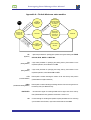
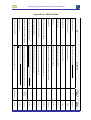
U N I V E R S I T Y O F AV E I R O DEPARTMENT OF ELECTRONICS, TELECOMMUNICATIONS AND INFORMATICS PROTOTYPING BOARD MANAGER USER MANUAL Complementary tool for use with the managing software of the DETIUA-S3 prototyping board (developed by Manuel Almeida, under the supervision of Full Professor Valery Sklyarov) and others of the same family. Bruno Figueiredo Pimentel PhD Student in Electrotechnic Engineering E-mail: [email protected] Jan. 2006 Prototyping Board Manager User Manual Contents 1. SYSTEM REQUIREMENTS................................................................................................................... 3 2. INSTALLATION ....................................................................................................................................... 3 3. TERMINOLOGY ...................................................................................................................................... 3 4. USER FLASH ADDRESSES AND USER SECTOR NUMBERS .................................................... 5 5. PBM MENUS............................................................................................................................................ 5 5.1. BOARD MENU................................................................................................................................... 5 5.1.1. Properties…................................................................................................................. 5 5.1.2. New board…................................................................................................................ 6 5.2. BITSTREAMS MENU ........................................................................................................................... 6 5.2.1. Upload user bitstream… .............................................................................................. 6 5.2.2. Upload alternative bitstreams…................................................................................... 6 5.2.3. Upload default bitstream… .......................................................................................... 8 5.3. DATA MENU ..................................................................................................................................... 8 5.3.1. Upload file… ................................................................................................................ 8 5.3.2. Download data… ......................................................................................................... 9 5.4. TOOLS MENU ................................................................................................................................. 10 5.4.1. Terminal window........................................................................................................ 10 5.4.2. Erase sectors… ......................................................................................................... 12 5.5. HELP MENU ................................................................................................................................... 12 5.5.1. User manual .............................................................................................................. 12 5.5.2. About…...................................................................................................................... 13 6. ERROR MESSAGES ............................................................................................................................ 13 7. PBM-COMPATIBLE BOARD DEVELOPING................................................................................... 14 7.1. BOARD ARCHITECTURE .................................................................................................................... 14 7.2. DEFAULT BITSTREAM ....................................................................................................................... 15 7.3. PBS FILE ....................................................................................................................................... 15 APPENDIX A – DEFAULT BITSTREAM STATE MACHINE................................................................ 17 APPENDIX B – PBS FILE FIELDS ........................................................................................................... 19 - 2 - Prototyping Board Manager User Manual 1. System requirements The current version of this software has not yet been subject to system requirements testing. Nevertheless, Prototyping Board Manager is expected to run correctly with Microsoft Windows operative systems. A Universal Serial Bus (USB) port is necessary in order to communicate with the prototyping boards. 2. Installation To install the Prototyping Board Manager application, simply extract the installation archive. Notes: Although the PBM folder location can be any, do not change the contents of that folder, otherwise the application might not run correctly. You might find useful to create a shortcut for this application’s executable file (“PBM.exe”, located in the chosen installation folder) in a more accessible location. Still, do not move the executable itself from the original folder. 3. Terminology PBM The acronym for Prototyping Board Manager, the name of the application this manual refers to. - 3 - Prototyping Board Manager User Manual PBS The acronym for Prototyping Board Specifications; the set of characteristics of a PBM-compatible board that PBM requires to be aware of in order to manage operations; the usual extension of the files with this information. Default bitstream The bitstream responsible to carry out PBM operation requests, with its own protected designated area within the board flash memory for easy loading into the FPGA (before PBM can operate with the board). User bitstream A bitstream for development purposes, with its own designated area within the board flash memory for easy loading into the FPGA. Alternative bitstreams Bitstreams for development purposes that are stored in predefined flash addresses within the user data area. Default bitstream area The first logical area of any PBM-compatible board’s flash memory; used to keep the default bitstream; out of the user flash addresses range. User bitstream area The second logical area of any PBM-compatible board’s flash memory; used to keep the user bitstream; out of the user flash addresses range. User data area The third logical area of any PBM-compatible board’s flash memory; mainly for free user access but also for storing alternative bitstreams; accessible with the user flash addresses range. User flash addresses Memory flash virtual addresses, with a correspondence to the real ones, but concealing the default bitstream area and the user bitstream area from the user, for safer board utilization. User sector numbers Flash sector virtual numbers, with a correspondence to the real ones, but concealing the default bitstream area and the user bitstream area from the user, for safer board utilization. User flash access macros Provided macros for creating bitstreams capable of accessing the board flash memory by providing user flash addresses and/or user sector numbers. - 4 - Prototyping Board Manager User Manual 4. User flash addresses and user sector numbers Certain flash sectors of PBM-compatible prototyping boards are reserved. Therefore, real flash addresses and real sector numbers are not used in Prototyping Board Manager dialogs, except when explicitly stated. Instead of those, the user can comfortably base himself on the so-called user flash addresses and user sector numbers and the Prototyping Board Manager will manage the necessary conversions. Notes: To support this abstraction approach in a coherent hardware design process, PBMcompatible prototyping boards come with proper flash user access macros. Check your board manual for more information on these macros. 5. PBM Menus 5.1. Board Menu 5.1.1. Properties… This function displays specifications of the prototyping board currently attached. This information is extracted from the correspondent PBS file. 1 - 5 - Prototyping Board Manager User Manual Legend: 1 Answering affirmatively will list the real starting flash addresses of all flash sectors. Answering negatively will exit this function. 5.1.2. New board… This feature allows you to install a new PBM-compatible prototyping board in order to use Prototyping Board Manager to work with it. Simply follow the straightforward dialog to specify the location of the PBS file provided with the board. 5.2. Bitstreams Menu 5.2.1. Upload user bitstream… This operation allows you to send a single bitstream with which you want to configure the FPGA. After you choose a valid bitstream file, the latter is sent to the board and stored in the user bitstream area of the flash memory. After this operation, this bitstream remains available for configuring the FPGA until you upload another user bitstream. Check your board manual for information on loading the user bitstream. 5.2.2. Upload alternative bitstreams… With this operation you can send multiple bitstreams to be stored in predefined positions within the user data area of the flash memory. After uploading the bitstreams you’ll need, you can configure the FPGA with either one of these socalled alternative bitstreams. Check your board manual to know how to use alternative bitstreams. - 6 - Prototyping Board Manager User Manual Notes: The user data area of the flash memory is intended to be freely accessed by users via Prototyping Board Manager and by their hardware solutions (by means of the flash user access macros). This means that transferring an alternative bitstream will overwrite user data eventually stored in the targeted location. Furthermore, careless access to the user data area of the flash memory might corrupt alternative bitstreams that were previously stored. All bitstream files must be subject to some changes before configuring the targeted FPGA. A subset of all the necessary changes occurs during the transfer to the prototyping board, thus you won’t find the original bitstream files stored in the flash memory. 1 2 3 Legend: 1 Change this number in order to choose a different location within the user data area of the flash memory to store the alternative bitstream. The correspondent user flash addresses interval to be overwritten is identified below this option. 2 Click this button to select and transfer the bitstream file you wish to store in the chosen position. 3 Click this button if you don’t wish to upload more alternative bitstreams. - 7 - Prototyping Board Manager User Manual 5.2.3. Upload default bitstream… This operation allows to replace the default bitstream stored in the respective reserved area of the board’s flash memory with a new one. The default bitstream is responsible for the interaction with the Prototyping Board Manager and, because it’s crucial, its designated area in the memory flash is protected by default. Do not use this operation unless you are fully aware of its consequences. 1 Legend: 1 Answering affirmatively will continue the replacement of the default bitstream. Answering negatively will cancel the operation. Do not answer affirmatively unless you are sure of what you are doing. 5.3. Data Menu 5.3.1. Upload file… This feature allows you to send any kind of file to the prototyping board and store it anywhere in the user area of its flash memory, for future access. 1 2 Before writing to any flash address, the whole sector which includes that address must first be erased eventually resulting in the unexpected loss of valuable data. - 8 - Prototyping Board Manager User Manual Prototyping Board Manager can overcome this problem by reading the data from the untargeted addresses of the first and last involved sectors and writing it back, along with the chosen file, after erasing those sectors. You will be prompted on whether to use this mechanism because it increases the overall operation time. 3 Legend: 1 Change this number to specify a different user address of the flash memory to start storing the file data. The resulting ending address is shown below this option. 2 Click this button to send the previously selected file and store it in the chosen location of the flash memory. 3 Answering affirmatively will guarantee that all data outside the targeted addresses interval is kept intact but the operation will take longer. Answering negatively will result in the loss of data eventually stored in untargeted addresses of the first and last involved sectors but the operation time will be shortened. 5.3.2. Download data… This feature allows you to read a data segment from anywhere in the user data area of the flash memory of the prototyping board and save it in your computer system as a file. 1 2 3 - 9 - Prototyping Board Manager User Manual Legend: 1 Change this number to specify a different user address of the flash memory to start reading the data. 2 Change this number to specify a different user address of the flash memory to stop reading the data. 3 Click this button to get the specified data segment of the flash memory and save it anywhere in your computer file system. 5.4. Tools Menu 5.4.1. Terminal window This tool is an integrated input and output peripheral which allows you to exchange raw bytes with the prototyping board via the USB connection. To exploit this tool, you can make use of the USB control macros of your PBMcompatible prototyping board in your designs. Check your board manual for more information on these macros. - 10 - Prototyping Board Manager User Manual 1 2 3 4 5 6 Legend: 1 Incoming bytes are shown in this text box, according to the coding mode (hexadecimal/ASCII). 2 Outgoing bytes are shown in this text box, according to the coding mode (hexadecimal/ASCII). 3 Write in this text box the set of bytes you wish to send, according to the coding mode (hexadecimal/ASCII). 4 Click this button to send the set of bytes you have written in the previous text box. The written bytes are first parsed according to the coding mode (hexadecimal/ASCII). When parsing illegal character sets, no bytes are sent and you will be notified. - 11 - Prototyping Board Manager User Manual 5 Use these radio buttons to choose between hexadecimal and ASCII coding modes. The byte displaying and parsing will be made according to this option. 6 Use this button to clear the text boxes of the Terminal Window. 5.4.2. Erase sectors… This feature allows you to erase sectors from the user area of the prototyping board’s flash memory. 1 2 3 1 Change this number in order to choose a different user sector to be erased. The correspondent user flash addresses interval that will be erased is identified below this option. 2 3 Click this button to erase the chosen user area sector. Click this button if you don’t wish to erase more sectors. 5.5. Help Menu 5.5.1. User manual This feature brings up the electronic version of this manual. The user manual is available both in English and Portuguese languages. - 12 - Prototyping Board Manager User Manual 5.5.2. About… This feature shows some information concerning the Prototyping Board Manager. 6. Error messages The following table indicates the most probable causes and the suggested actions to carry out for the different error messages that you might encounter. Error messages: Probable causes: “The following file is already installed: (…) Please choose an external PBS file to install.” A PBS file from the “PBS_files” folder was selected for installation. Select the PBS file provided when you acquired the board you are trying to install. “The following file is not a valid PBS file: (…)” The file indicated is not the PBS file provided with the board or has become corrupted. Select an intact version of the PBS file provided when you acquired the board you are trying to install. “No prototyping board detected. Please, attach one to continue." The prototyping board is not attached. Attach the prototyping board and retry. “Alternative devices connected. Make sure only one device is attached to continue.” More than one prototyping board is attached. Detach all boards except the one you are trying to access. “Unable to connect with the prototyping board. Please, reset the board to retry.” n/a Detach the prototyping board and reattach it. “The prototyping board is not responding as expected. Please, reset the board and then try again.” The prototyping board default bitstream has not been loaded to the FPGA. Load the prototyping board default bitstream and retry. Check your board manual to know how to do this. “The selected file is not a valid bitstream file. Please choose another one.” The selected file is not a valid bitstream file. Select a valid bitstream file. “The size of the selected file does not match the size for this prototyping board's FPGA. Please choose another one.” The selected file is not a valid bitstream file for the targeted FPGA. Select a bitstream which is valid for the targeted FPGA. “The selected file exceeds the flash user data area size. Please select another file to proceed.” The selected file does not fit the user data area of the board’s flash memory. Select a smaller file to upload. “The size of the selected file is null. Please select another file to proceed.” The size of the selected file is null. Select a positive sized file to upload. - 13 - Suggested actions: Prototyping Board Manager User Manual Error messages: Probable causes: Suggested actions: “Error determining the (…).” The PBS file associated with the prototyping board is corrupted. Reinstall the board via the ‘Board’ menu. “The prototyping board has been detached. Aborting operation.” The prototyping board is no longer attached. Reattach the prototyping board and retry. “The prototyping board has become desynchronized. Aborting operation.” A bitstream was loaded into the FPGA while PBM was communicating with the prototyping board. Reload the prototyping board default bitstream. Check your board manual to know how to do this. “No flash sector with the starting address that was sent.” The PBS file associated with the prototyping board is corrupted. Reinstall the board via the ‘Board’ menu. “Access denied when trying to write to the protected flash area.” The reserved flash area protection is active. Check your board manual to know how to bypass this protection measure. “Communication Protocol Violation Error: (…)” A bitstream was loaded into the FPGA while PBM was communicating with the prototyping board. Reload the prototyping board default bitstream. Check your board manual to know how to do this. “Unable to open (…)” The requested user manual PDF file has been removed from the PBM folder or cannot be accessed. Reinstall PBM. 7. PBM-compatible board developing When developing an FPGA based prototyping board, a set of conditions have to be satisfied in order to be compatible with the Prototyping Board Manager. 7.1. Board architecture Regarding the architecture, the board must include: an USB controller that uses the FTD2XX.dll driver, in which the Product id must be set to a value unique to that model; a flash memory, verifying the following conditions: The flash memory must be logically divided in 3 areas: in the following order: default bitstream area, user bitstream area and user data area; The logical areas must be consecutive and exclusive sectors sets; - 14 - Prototyping Board Manager User Manual Each of the first two logical areas must be big enough to store one bitstream (without header) for the board’s FPGA; a way to configure the FPGA either with the bitstream stored in the default bitstream area or with the bitstream stored in the user bitstream area; a means of protection against writing to the default bitstream area, providing a 1 bit sized signal to indicate whether the protection is active or not, accessible to the FPGA (to be used by the default bitstream). Notes: Because PBM uses 3 byte sized memory flash addresses, it can only address up to 16 megabytes. This doesn’t mean that you cannot use a bigger memory flash. Although PBM protects against involuntary overwriting of the default bitstream stored in the first logical area of the flash memory, a permanent hardware mechanism is recommended to protect against unsafe bitstreams loaded into the FPGA. 7.2. Default bitstream A default bitstream must be created and verify the following: It must implement the functionality of the state machine described in Appendix A; It is not responsible for discarding the headers of transferred bitstreams (PBM will do this previously to sending); It is responsible for inverting the bit order within each byte of transferred bitstreams (either when receiving it, or when loading it into the FPGA); It must be stored in the first logical area of the flash memory, before it can be accessed via PBM. 7.3. PBS file A file with the board’s specifications must be created taking into account the following: The file must be an unformatted 8-bit coded text file, composed by a sequence of fields; - 15 - Prototyping Board Manager User Manual Each field is composed by a tag line followed by one or more value lines; The set of fields that must be provided and the correspondent representation guidelines are presented in Appendix B; The file extension should be “.pbs” for a coherent and easy identification. - 16 - Prototyping Board Manager User Manual Appendix A – Default bitstream state machine start S Receive OP, receive SA, receive EA EA A= R O > EA A LF else O P P R SA ≠ R O < U EA TE B D CT SA AN ED AN D =T D RU E OP (Operation) SA (Starting Address) EA (Ending Address) LFA (Last Flash Address) UBSA (User Bitstream Starting Address) PROTECTED Send ADDRESS ERROR R O V TE _IN I R E W IT P= W R O = P O Send OK O P= OP=READ ER AS Send PROTECTION ERROR E_ SE CT O R Receive and write bytes from SA to EA according to OP Read and send bytes stored from SA to EA Send OK Erase sector with SA 1 byte sized parameter for specifying the operation among the following set: ERASE SECTOR, READ, WRITE and WRITE INV. 3 byte sized parameter for specifying the starting memory flash address for the requested operation; valid if between 0 and EA. 3 byte sized parameter for specifying the ending memory flash address for the requested operation; valid if between SA and LFA. Board-specific constant indicating the address of the last memory flash position (addressable with 3 bytes addresses). Board-specific constant indicating the starting address of the second logical area of the memory flash (user bitstream area). 1 bit sized board signal for indicating whether the first logical area of the memory flash (default bitstream area) protection mechanism is active or not. OK Control message for validating the operation request parameters and for confirming synchronization when finished; 1 byte sized constant with the value 0x01. - 17 - Prototyping Board Manager User Manual PROTECTION ERROR Control message for denying a request operation when trying to write in the first logical area of the flash memory (default bitstream area) with the protection mechanism active; 1 byte sized constant with the value 0x02. ADDRESS ERROR Control message for denying a request operation due to invalid SA and EA parameter set; 1 byte sized constant with the value 0x03. ERASE SECTOR OP assignment for requesting a sector erasure; 1 byte sized constant with the value 0x04. READ OP assignment for requesting a memory flash reading; 1 byte sized constant with the value 0x05. WRITE OP assignment for requesting a simple memory flash writing; 1 byte sized constant with the value 0x06. WRITE INV OP assignment for requesting a memory flash writing with bit order inversion within (Write Inverted) each byte; used for transferring bitstreams; 1 byte sized constant with the value 0x07. - 18 - Prototyping Board Manager User Manual Appendix B – PBS file fields USER_BITSTREAM_STARTING_ADDRESS DEFAULT_BITSTREAM_STARTING_ADDRESS BITSTREAM_SIZE FLASH_SIZE MAX_ERASE_TIME FPGA_DESCRIPTION PROTOTYPING_BOARD_NAME PROTOTYPING_BOARD_ID Real memory flash starting address of the user data area. Real memory flash starting address of the user bitstream area. Real memory flash starting address of the default bitstream area. Number of bytes of the bitstreams for the board’s FPGA, excluding header. Total number of bytes in the flash memory. Worst-case flash memory sector erasing time. Description of the board’s FPGA. Prototyping board model name. Product ID stored in the USB controller; must precede all other fields. 1 1 1 1 1 1 1 1 1 1 Number of values Base 16 Base 10 Base 16 Base 16 Base 16 Base 10 Base 10 Base 10 String String Base 10 Value(s) parsing Observations USER_DATA_STARTING_ADDRESS Number of predefined bitstream locations within the user data area; must precede the alternative bitstreams starting addresses field. number of alternative bitstreams Tag MAX_NUMBER_OF_ALTERNATIVE_BITSTREAMS Real memory flash starting addresses of the predefined alternative bitstream locations. ALTERNATIVE_BITSTREAMS_STARTING_ADDRESSES Base 10 Number of total memory flash sectors; must precede the sectors starting addresses field. 1 NUMBER_OF_SECTORS Base 16 Real starting addresses of all memory flash sectors. number of sectors SECTORS_STARTING_ADDRESSES - 19 -