1
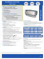
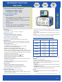
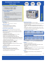
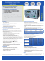
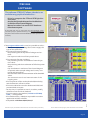
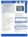
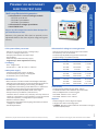
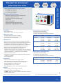
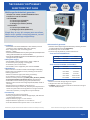
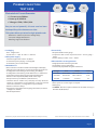
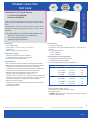
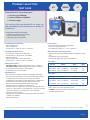
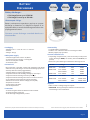
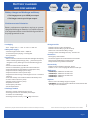
SECONDARY INJECTION TEST CASE
Page de 2 à 9
SOFTWARE
Page de 10 à 11
SUMMARY
SUMMARY
PRIMARY OR SECONDARY INJECTION TEST CASE
Page de 12 à 15
PRIMARY INJECTION TEST CASE
Page de 16 à 18
BATTERY DISCHARGER
Page de 19 à 22
POWER SUPPLY
Page de 23 à 23
TOOLS
Garantie un an pièces et main d’oeuvre, intervention effectuée exclusivement en notre usine.
Ces caractéristiques techniques peuvent évoluer du fait des améliorations apportées.
Parc d’activités de Ravennes les Francs - B.P80009
59588 BONDUES Cedex - FRANCE
Tel : +33 (0)3 20 11 52 00 - Fax : +33 (0)3 20 11 52 11
[email protected]
www.francelog.com
Page 1
01/12
Page de 24 à 28
Secondary injection
test case
150V
3U
3I
12.5A
High accuracy electronic generator :
• 3 Voltages up to 150Vac - 50VA
• 3 Current up to 12.5Aac - 100VA max
DTR 133 / 033
Converter input :
Only working with PTRPILOT software :
• Driving mode thanks to the PTRPILOT software running on Windows XP/NT/Vista/7.
Dimensions and Weight reduced
Transducer and Converter tests
• Packaging
• Laboratory box with a handle.
• Dimensions : L = 430 - D = 465 - H = 289 mm.
• Main power supply
• 230 Vac Single Phase + Earth - 50 /60 Hz.
• Connection by Europa plug - Cord supplied.
• Protected by mini circuit-breaker.
• PTRPILOT®
Driving software for DTR allowing the following operations :
• Configuration of the test type.
• Configuration of the setting mode «normal» or «fault».
• Selection of current and/or voltage ranges.
• Measure of the amplitude (RMS) : 0.1% of the range.
• Control of current and/or voltage injection and start of the
timer when the configuration changes between «normal» and
«fault» state. Timer stops automatically when receiving an
information on «stop» terminals.
• Frequency measure (accuracy 0.01Hz + 1 digit).
• Phase angle measure (accuracy 1° + 1 digit).
• Delay measure up to 2000 sec (resolution 1ms).
• Measure of recloser delays.
• Recognition of the state of the tripping information (contact or
voltage 24 to 240Vdc).
• Automatic measure of the tripping value (hold function).
• Serial output RS232.
• External converter inputs
• 1 External current measure input : 0/20mAdc.
• 1 External voltage measure input : 0/10Vdc.
• Contact relay outputs
• Contact relay output coupled to the injection.
• Contact relay NO/NC : 125Vmax - 1A.
Picture for illustration purposes only.
• 1 Input 0/20 mAdc
• 1 Input 0/10 Vdc
• Electronic generators
• Electronically controlled current and voltage.
• Protection against overload, led indicator and reset switch.
• Frequency : Fixed 50Hz - Adjustable from 40 to 65Hz by
0.01Hz steps.
• Phase angle : Adjustable from 0 to 360°.
3 Current generators (choose the range when ordering)
Models
Current
Voltage
Power
DTR133 - 12A5
DTR133 - 5A
DTR033 - 12A5
DTR033 - 5A
12.5A
5A
12.5A
5A
8V
20V
4V
10V
100VA
100VA
50VA
50VA
3 Voltage generators (choose the range when ordering)
Range
Time
Imax
Power
0 to 150Vac
Permanent
0,33A
50VA
• Connectivity
• Output voltage, current and timer security plugs : Ø4mm.
• Options
• Transportation Pelicase.
• DTRX33-M : Manuel adjustment by potentiometers and visualization display.
• Main power supply : 115Vac.
• Frequency : variable from 40 to 400 Hz by 0.1Hz steps.
• Auxiliary power supply : 24 / 48 / 127 / 250Vcc (15W).
• Other voltage or current ranges on request.
• Divers
Guarantee one year parts and labor. All interventions are carried out exclusively in our factory.
Due to continuous research program, these characteristics can be modified.
Page 2
01/12
• This material is CEM certified according to EN50081-2 and
EN50082-2.
Secondary injection
test case
300V
3U
3I
50A
High accuracy electronic generator:
PTR33U + PTR33I
• PTR33/U : 3 Voltages up to 300Vac - 100VA
• PTR33/I : 3 Currents up to 50Aac - 150VA
• Packaging
• 2 boxes - «Flight Case» .
• Dimensions : 2 x L = 400 - W = 295 - H = 400 mm.
• Main power supply
• 230 Vac Single Phase + Earth - 50 /60 Hz.
• Connection by Europa plug - Cord supplied.
• Wiring cord to connect PTR33/U.
• Protected by mini circuit-breaker.
• Fixed auxiliary voltage supply
• 24 / 48 / 127 / 250 Vcc (15W). Selection by switch button.
• MICROPILOT® (Usually implanted on current box)
Microcontroller controlled module with backlight LCD display,
function keys, and navigation menus, allowing to excecute the
following operations :
• Configuration of the test type.
• Configuration of the setting mode «normal» or «fault».
• Selection of current and voltage ranges.
• Injection control of current and/or voltage.
• Display current, voltage and homopolar values.
• Measure of the amplitude (RMS) : 0.2% of the range.
• Control of current and/or voltage injection and start of the
timer when the configuration changes between «normal» and
«fault» state. Timer stops automatically when receiving an
information on «stop» terminals.
• Frequency measure (accuracy 0.01Hz + 1 digit).
• Phase angle measure (accuracy 1° + 1 digit).
• Delay measure up to 2000 sec (resolution 1ms).
• Measure of recloser delays.
• Recognition of the state of the tripping information (contact or
voltage 24 to 240Vdc).
• Automatic measure of the tripping value (hold function).
• Serial output RS232.
• Connectivity
• Wiring cord to connect PTR33U and PTR33I.
• Output current lockable security plugs : ø6mm.
• Output voltage and timer security plugs : ø4mm.
• Lockable threaded rods suitable to current terminals.
• ø6 / ø4 adaptators for current terminals.
Guarantee one year parts and labor. All interventions are carried out exclusively in our factory.
• Electronic generators
• Electronically controlled current and voltage.
• Adjustment with potentiometers by 0.01A steps for current
and 0.1V steps for voltage.
• Protection against overload, led indicator and reset switch.
• Frequency : Fixed 50Hz - Adjustable from 40 to 65Hz by
0.01Hz steps.
• Phase angle : Adjustable from 0 to 360° using «+» and «-»
keys.
• Possibility to simulate a homopolar voltage phase opposed
with U1 voltage without distort the RST triangle.
3 Voltage generators 100VA :
Range U
75V
150V
300V
I max.
1.33A
0.66A
0.33A
Time
Permanent
Permanent
Permanent
3 Current generators 150VA :
Range I
5A
12.5A
25A
50A
U max.
30V
12V
6V
3V
Time
10 min
10 min
5 min
1 min
Version PTR33I : 3 current ranges 5A/25A/50A (200VA).
Version PTR33IP : 3 current ranges 5A/12,5A/25A (200VA).
Version PTR33IN : 3 current ranges 12.5A/25A/50A (200VA).
• Options
• Main power supply 115Vac.
• Frequency : 40 to 400 Hz by 0.1Hz steps.
• Auxiliary power supply : 24 / 48 / 127Vcc (15W) / 100Vca (15VA).
• Other voltage or current ranges on request.
• Rolling tray : PTR33U-PR, PTR33I-PR
• CTRWIN : Real time capture software of all results running on
Windows XP/NT/Vista/7
• PTRPILOT : Driving software running on Windows XP/NT/
Vista/7. Purposes both manual and driving modes.
• Others
• This Material is CEM certified according to EN50081-2 and
EN50082-2.
Due to continuous research program, these characteristics can be modified.
Page 3
01/12
• Manual Mode :
- Manual adjustment of the different injection values
by push button and potentiometers.
- Test configuration thanks to the MICROPILOT®
menus.
• Driving Mode:
- Driving mode thanks to the PTRPILOT software
running under Windows XP/NT/Vista/7.
Picture for illustration purposes only.
Two user modes available :
Secondary injection
test case
300V
3U
3I
50A
High accuracy electronic generator :
• 3 Voltages up to 300Vac - 50VA
• 3 Current up to 50Aac - 200VA
• Packaging
• Box - «Flight Case».
• Dimensions : L = 535 - W = 450 - H = 460 mm.
• Main power supply
• 230 Vac Single Phase + Earth - 50 /60 Hz.
• Connection by Europa plug - Cord supplied.
• Protected by mini circuit-breaker.
• Fixed auxiliary voltage supply
• 24 / 48 / 127 / 250 Vcc (15W). Selection by switch button.
• MICROPILOT®
Microcontroller controlled module with backlight LCD display,
function keys, and navigation menus, allowing to excecute the
following operations :
• Configuration of the test type.
• Configuration of the setting mode «normal» or «fault».
• Choice of current and voltage ranges.
• Display current, voltage and homopolar values.
• Measure of the amplitude (RMS) : 0.2% of the range.
• Control of current and/or voltage injection and start of the
timer when the configuration changes between «normal» and
«fault» state. Timer stops automatically when receiving an
information on «stop» terminals.
• Frequency measure (accuracy 0.01Hz + 1 digit).
• Phase angle measure (accuracy 1° + 1 digit).
• Delay measure up to 2000 sec (resolution 1ms).
• Measure of recloser delays.
• Recognition of the state of the tripping information (contact or
voltage 24 to 240Vdc).
• Automatic measure of the tripping value (hold function).
• Serial output RS232.
• Connectivity
• Output current lockable security plugs : ø6mm.
• Output voltage and timer security plugs : ø4mm.
• Lockable threaded rods suitable to current terminals.
• ø6 / ø4 adaptators for current terminals.
Picture for illustration purposes only.
• Manual Mode :
- Manual adjustment of the different injection values
by push button and potentiometers.
- Test configuration thanks to the MICROPILOT®
menus.
• Driving Mode:
- Driving mode thanks to the PTRPILOT software
running under Windows XP/NT/Vista/7.
PTR 233
Two user modes available :
• Electronic generators
• Electronically controlled current and voltage.
• Adjustment with potentiometers by 0.01A steps for current
and 0.1V steps for voltage.
• Protection against overload, led indicator and reset switch.
• Frequency : Fixed 50Hz - Adjustable from 40 to 65Hz by
0.01Hz steps.
• Phase angle : Adjustable from 0 to 360° using «+» and «-»
keys.
• Possibility to simulate a homopolar voltage phase opposed
with U1 voltage without distort the RST triangle.
3 Voltage generators 50VA :
Range U
75V
150V
300V
I max.
0.66A
0.33A
0.16A
Time
Permanent
Permanent
Permanent
3 Current generators 200VA :
Range I
5A
12.5A
25A
50A
U max.
40V
16V
8V
3V
Time
10 min
10 min
5 min
1 min
Version PTR233 : 3 current ranges 5A/25A/50A (200VA).
Version PTR233-P : 3 current ranges 5A/12,5A/25A (200VA).
Version PTR233-N : 3 current ranges 12,5A/25A/50A (200VA).
• Options
• Main power supply 115Vac.
• Frequency : 40 to 400 Hz by 0.1Hz steps.
• Auxiliary power supply : 24 / 48 / 127Vcc (15W) / 100Vca (15VA).
• Other voltage or current ranges on request.
• Rolling tray.
• CTRWIN : Real time capture software of all results running on
Windows XP/NT/Vista/7.
• PTRPILOT : Driving software running on Windows XP/NT/
Vista/7. Purposes both manual and driving modes.
• This Material is CEM certified according to EN50081-2 and
EN50082-2.
Guarantee one year parts and labor. All interventions are carried out exclusively in our factory.
Due to continuous research program, these characteristics can be modified.
Page 4
01/12
• Others
Secondary injection
test case
300V
25A
3U
3I
High accuracy electronic generator :
PTRS 133 / 033
• 3 Voltages up to 300Vac - 50VA
• 3 Current up to 25Aac - 100VA
• Packaging
• Box - «Flight Case».
• Dimensions : L = 535 - W = 320 - H = 460 mm.
• Main power supply
• 230 Vac Single Phase + Earth - 50 /60 Hz.
• Connection by Europa plug - Cord supplied.
• Protected by mini circuit-breaker.
• Fixed auxiliary voltage supply
• 24 / 48 / 127 / 250 Vcc (15W). Selection by switch button.
• MICROPILOT®
Microcontroller controlled module with backlight LCD display,
function keys, and navigation menus, allowing to excecute the
following operations :
• Configuration of the test type.
• Configuration of the setting mode «normal» or «fault».
• Choice of current and voltage ranges.
• Display current, voltage and homopolar values.
• Measure of the amplitude (RMS) : 0.2% of the range.
• Control of current and/or voltage injection and start of the
timer when the configuration changes between «normal» and
«fault» state. Timer stops automatically when receiving an
information on «stop» terminals.
• Frequency measure (accuracy 0.01Hz + 1 digit).
• Phase angle measure (accuracy 1° + 1 digit).
• Delay measure up to 2000 sec (resolution 1ms).
• Measure of recloser delays.
• Recognition of the state of the tripping information (contact or
voltage 24 to 240Vdc).
• Automatic measure of the tripping value (hold function).
• Serial output RS232.
• Connectivity
• Output current lockable security plugs : ø6mm.
• Output voltage and timer security plugs : ø4mm.
• Lockable threaded rods suitable to current terminals.
• ø6 / ø4 adaptators for current terminals.
• Electronic generators
• Electronically controlled current and voltage.
• Adjustment with potentiometers by 0.01A steps for current
and 0.1V steps for voltage.
Guarantee one year parts and labor. All interventions are carried out exclusively in our factory.
• Protection against overload, led indicator and reset switch.
• Frequency : Fixed 50Hz - Adjustable from 40 to 65Hz by
0.01Hz steps.
• Phase angle : Adjustable from 0 to 360° using «+» and «-»
keys.
• Possibility to simulate a homopolar voltage phase opposed
with U1 voltage without distort the RST triangle.
3 Voltage 50VA and Current 100VA generators :
Model
133V6A
133V6B
133V6C
133V6D
133V6E
Voltage Ranges
(I max.)
Current Ranges
(U max.)
150 V
(0.33A)
300V
(0.16A)
150V
(0.33A)
300V
(0.16A)
150V
(0.33A)
12.5A
(8V)
12.5A
(8V)
5A
(20V)
25A
(4V)
25A
(4V)
Option : PTRS033 identical to the PTRS133 except current power to 50VA
• Options
• Main power supply 115Vac.
• Frequency : 40 to 400 Hz by 0.1Hz steps.
• Auxiliary power supply : 24 / 48 / 127 Vcc (15W) 100Vca (15VA).
• Other voltage or current ranges on request.
• Rolling tray.
• CTRWIN : Real time capture software of all results running on
Windows XP/NT/Vista/7
• PTRPILOT : Driving software running on Windows XP/NT/
Vista/7. Purposes both manual and driving modes.
• Others
• This Material is CEM certified according to EN50081-2 and
EN50082-2.
Due to continuous research program, these characteristics can be modified.
Page 5
01/12
• Manual Mode :
- Manual adjustment of the different injection values
by push button and potentiometers.
- Test configuration thanks to the MICROPILOT®
menus.
• Driving Mode:
- Driving mode thanks to the PTRPILOT software
running under Windows XP/NT/Vista/7.
Picture for illustration purposes only.
Two user modes available :
300V
2I
3U+1I
50A
High accuracy electronic generator :
• 3 Voltages up to 300Vac - 50VA
• 1 + 2 Currents up to 50Aac - 200VA
• Packaging
• 2 boxes - «Flight Case».
• Dimensions : 2 x L = 400 - W = 295 - H = 400 mm.
• Main power supply
• 230Vac Single Phase + Earth - 50 /60 Hz.
• Connection by Europa plug - Cord supplied.
• Wiring Cord to connect PTRS002E.
• Protected by mini circuit-breaker.
• Fixed auxiliary voltage supply
• 24 / 48 / 127 / 250 Vcc (15W). Selection by switch button.
• MICROPILOT®
Microcontroller controlled module with backlight LCD display,
function keys, and navigation menus, allowing to excecute the
following operations :
• Configuration of the test type.
• Configuration of the setting mode «normal» or «fault».
• Choice of current and voltage ranges.
• Display current, voltage and homopolar values.
• Measure of the amplitude (RMS) : 0.2% of the range.
• Control of current and/or voltage injection and start of the
timer when the configuration changes between «normal» and
«fault» state. Timer stops automatically when receiving an
information on «stop» terminals.
• Frequency measure (accuracy 0.01Hz + 1 digit).
• Phase angle measure (accuracy 1° + 1 digit).
• Delay measure up to 2000 sec (resolution 1ms).
• Measure of recloser delays.
• Recognition of the state of the tripping information (contact or
voltage 24 to 240Vdc).
• Automatic measure of the tripping value (hold function).
• Serial output RS232.
• Connectivity
• Link cable between PTRS231 and PTRS002E.
• Output current lockable security plugs : ø6mm.
• Output voltage and timer security plugs : ø4mm.
• Lockable threaded rods suitable to current terminals.
• ø6 / ø4 adaptators for current terminals.
Guarantee one year parts and labor. All interventions are carried out exclusively in our factory.
• Electronic generators
• Electronically controlled current and voltage.
• Adjustment with potentiometers by 0.01A steps for current
and 0.1V steps for voltage.
• Protection against overload, led indicator and reset switch.
• Frequency : Fixed 50Hz - Adjustable from 40 to 65Hz by
0.01Hz steps.
• Phase angle : Adjustable from 0 to 360° using «+» and «-»
keys.
• Possibility to simulate a homopolar voltage phase opposed
with U1 voltage without distort the RST triangle.
3 Voltage generators de tension 50VA :
Range U
75V
150V
300V
I max.
0.66A
0.33A
0.16A
Time
Permanent
Permanent
Permanent
3 Current generators 200VA :
Range I
5A
12.5A
25A
50A
U max.
40V
16V
8V
4V
Time
10 min
10 min
5 min
1 min
Version PTRS231 : 3 current ranges 12.5A/25A/50A (200VA).
Version PTRS231P : 3 current ranges 5A/12.5A/25A (200VA).
• Options
• Main power supply 115Vac.
• Frequency : 40 to 400 Hz by 0.1Hz steps.
• Auxiliary power supply : 24 / 48 / 127Vcc (15W) 100Vca (15VA).
• Other voltage or current ranges on request.
• Rolling tray.
• CTRWIN : Real time capture software of all results running on
Windows XP/NT/Vista/7
• PTRPILOT : Driving software running on Windows XP/NT/
Vista/7. Purposes both manual and driving modes.
• Others
• This Material is CEM certified according to EN50081-2 and
EN50082-2.
Due to continuous research program, these characteristics can be modified.
Page 6
01/12
• Manual Mode :
- Manual adjustment of the different injection values
by push button and potentiometers.
- Test configuration thanks to the MICROPILOT®
menus.
• Driving Mode:
- Driving mode thanks to the PTRPILOT software
running under Windows XP/NT/Vista/7.
Picture for illustration purposes only.
Two user modes available :
PTRS231 + PTRS002E
Secondary injection
test case
Secondary injection
test case
300V
3U
1I
50A
High accuracy electronic generator :
• 3 Voltages up to 300Vac - 50VA
• 1 Current up to 50Aac - 200VA
• Packaging
• Box - «Flight Case».
• Dimensions : L = 400 - W = 295 - H = 400 mm.
• Main power supply
• 230 Vac Single Phase + Earth - 50 /60 Hz.
• Connection by Europa plug - Cord supplied.
• Protected by mini circuit-breaker.
• Fixed auxiliary voltage supply
• 24 / 48 / 127 / 250 Vcc (15W). Selection by switch button.
• MICROPILOT®
Microcontroller controlled module with backlight LCD display,
function keys, and navigation menus, allowing to excecute the
following operations :
• Configuration of the test type.
• Configuration of the setting mode «normal» or «fault».
• Choice of current and voltage ranges.
• Display current, voltage and homopolar values.
• Measure of the amplitude (RMS) : 0.2% of the range.
• Control of current and/or voltage injection and start of the
timer when the configuration changes between «normal» and
«fault» state. Timer stops automatically when receiving an
information on «stop» terminals.
• Frequency measure (accuracy 0.01Hz + 1 digit).
• Phase angle measure (accuracy 1° + 1 digit).
• Delay measure up to 2000 sec (resolution 1ms).
• Measure of recloser delays.
• Recognition of the state of the tripping information (contact or
voltage 24 to 240Vdc).
• Automatic measure of the tripping value (hold function).
• Serial output RS232.
• Connectivity
• Output current lockable security plugs : ø6mm.
• Output voltage and timer security plugs : ø4mm.
• Lockable threaded rods suitable to current terminals.
• ø6 / ø4 adaptators for current terminals.
Picture for illustration purposes only.
• Manual Mode :
- Manual adjustment of the different injection values
by push button and potentiometers.
- Test configuration thanks to the MICROPILOT®
menus.
• Driving Mode:
- Driving mode thanks to the PTRPILOT software
running under Windows XP/NT/Vista/7.
PTRS 231
Two user modes available :
• Electronic generators
• Electronically controlled current and voltage.
• Adjustment with potentiometers by 0.01A steps for current and
0.1V steps for voltage.
• Protection against overload, led indicator and reset switch.
• Frequency : Fixed 50Hz - Adjustable from 40 to 65Hz by 0.01Hz
steps.
• Phase angle : Adjustable from 0 to 360° using «+» and «-» keys.
• Possibility to simulate a homopolar voltage phase opposed with
U1 voltage without distort the RST triangle.
3 Voltage generators 50VA :
Range U
75V
150V
300V
I max.
0.66A
0.33A
0.16A
Time
Permanent
Permanent
Permanent
1 Current generator 200VA :
Range I
5A
12.5A
25A
50A
U max.
40V
16V
8V
4V
Time
10 min
10 min
5 min
1 min
Version PTRS231P : 3 current ranges 5A/12,5A/25A (200VA).
Version PTRS231 : 3 current ranges 12,5A/25A/50A (200VA).
• Options
• Main power supply 115Vac.
• Frequency : 40 to 400 Hz by 0.1Hz steps.
• Auxiliary power supply : 24 / 48 / 127Vcc (15W) 100Vca (15VA).
• Other voltage or current ranges on request.
• Rolling tray.
• CTRWIN : Real time capture software of all results running on
Windows XP/NT/Vista/7.
• PTRPILOT : Driving software running on Windows XP/NT/
Vista/7. Purposes both manual and driving modes.
• Others
Guarantee one year parts and labor. All interventions are carried out exclusively in our factory.
Due to continuous research program, these characteristics can be modified.
Page 7
01/12
• This Material is CEM certified according to EN50081-2 and
EN50082-2.
Secondary injection
test case
300V
3U
1I
200A
max
High accuracy electronic generator :
• 3 Voltages up to 300Vac - 50VA
1 electrotechnic current generator :
• PTR531E-200A : 1 current up to 200Aac
• PTR531E-100A : 1 current up to 100Aac
• Power max : 500VA
• Packaging
• Box - «Flight Case».
• Dimensions : L = 535 - W = 450 - H = 460 mm.
• Main power supply
• 230 Vac Single Phase + Earth - 50 /60 Hz.
• Connection by Europa plug - Cord supplied.
• Protected by mini circuit-breaker.
• Fixed auxiliary voltage supply
• 24 / 48 / 127 / 250 Vcc (15W). Selection by switch button.
• MICROPILOT®
Microcontroller controlled module with backlight LCD display,
function keys, and navigation menus, allowing to excecute the
following operations :
• Configuration of the test type.
• Configuration of the setting mode «normal» or «fault».
• Choice of current and voltage ranges.
• Display current, voltage and homopolar values.
• Measure of the amplitude (RMS) : 0.2% of the range.
• Control of current and/or voltage injection and start of the
timer when the configuration changes between «normal» and
«fault» state. Timer stops automatically when receiving an
information on «stop» terminals.
• Frequency measure (accuracy 0.01Hz + 1 digit).
• Phase angle measure (accuracy 1° + 1 digit).
• Delay measure up to 2000 sec (resolution 1ms).
• Measure of recloser delays.
• Recognition of the state of the tripping information (contact or
voltage 24 to 240Vdc).
• Automatic measure of the tripping value (hold function).
• Serial output RS232.
• Connectivity
• Output current lockable security plugs : ø6mm.
• Output voltage and timer security plugs : ø4mm.
• Lockable threaded rods suitable to current terminals
• ø6 / ø4 adaptators for current terminals.
• Câbles 2 x 2.5m - 50mm².
Picture for illustration purposes only.
- Manual adjustment of the different injection values
by push button and potentiometers.
- Test configuration thanks to the MICROPILOT®
menus.
PTR 531E
Manual mode :
• 3 Electronic generators 50VA
• Electronically controlled current and voltage.
• Adjustment with potentiometers by 0.01A steps for current and
0.1V steps for voltage.
• Protection against overload, led indicator and reset switch.
• Frequency : Fixed 50Hz - Adjustable from 40 to 65Hz by 0.01Hz
steps.
• Phase angle : Adjustable from 0 to 360° using «+» and «-» keys.
• Possibility to simulate a homopolar voltage phase opposed with
U1 voltage without distort the RST triangle.
Range U
75V
150V
300V
I max.
0.66A
0.33A
0.16A
Time
Permanent
Permanent
Permanent
• 1 Electrotechnic current generator 500VA
• Protected by mini circuit-breaker.
• Continuously adjustable using an auto-transformer.
• Use of an output transformer (500VA).
• Output ranges switching knob.
PTR531E-100A
PTR531E-200A
Range I
U max
Time
10A
50A
100A
10A
50A
200A
2 or 50V
5 or 10V
2.5 or 5V
2 or 50V
5 or 10V
1.25 or 2.5V
Permanent
1 min
1 min
Permanent
1 min
1 min
• Options
• Main power supply 115Vac.
• Frequency : 40 to 400 Hz by 0.1Hz steps.
• Auxiliary power supply : 24 / 48 / 127Vcc (15W) / 100Vca (15VA).
• Other voltage or current ranges on request.
• Rolling tray : PTR531E - PR.
• CTRWIN : Real time capture software of all results running on
Windows XP/NT/Vista/7.
• This material is CEM certified according to EN 50081-2 and
EN 50082-2.
Guarantee one year parts and labor. All interventions are carried out exclusively in our factory.
Due to continuous research program, these characteristics can be modified.
Page 8
01/12
• Other
Secondary injection
test case
300V
1U
1I
50A
High accuracy electronic generator :
• 1 Voltage up to 300Vac - 50VA
• 1 Current up to 50Aac - 200VA
• Box - «Flight Case».
• Dimensions : L = 400 - W = 295 - H = 460 mm.
• Main power supply
• 230 Vac Single Phase + Earth - 50 /60 Hz.
• Connection by Europa plug - Cord supplied.
• Protected by mini circuit-breaker.
• Fixed auxiliary voltage supply
• 24 / 48 / 127 / 250 Vcc (15W). Selection by switch button.
• MICROPILOT®
Microcontroller controlled module with backlight LCD display,
function keys, and navigation menus, allowing to excecute the
following operations :
• Configuration of the test type.
• Configuration of the setting mode «normal» or «fault».
• Choice of current and voltage ranges.
• Display current, voltage values.
• Measure of the amplitude (RMS) : 0.2% of the range.
• Control of current and/or voltage injection and start of the
timer when the configuration changes between «normal» and
«fault» state. Timer stops automatically when receiving an
information on «stop» terminals.
• Frequency measure (accuracy 0.01Hz + 1 digit).
• Phase angle measure (accuracy 1° + 1 digit).
• Delay measure up to 2000 sec (accuracy 1ms).
• Measure of recloser delays.
• Recognition of the state of the tripping information (contact or
voltage 24 to 240Vdc).
• Automatic measure of the tripping value (hold function).
• Serial output RS232.
• Connectivity
• Output current lockable security plugs : ø6mm.
• Output voltage and timer security plugs : ø4mm.
• Lockable threaded rods suitable to current terminals.
• ø6 / ø4 adaptators for current terminals.
• Electronic generators
• Electronically controlled current and voltage.
• Adjustment with potentiometers by 0.01A steps for current
and 0.1V steps for voltage.
• Protection against overload, led indicator and reset switch.
• Frequency : Fixed 50Hz - Adjustable from 40 to 65Hz by
0.01Hz steps.
• Phase angle : Adjustable from 0 to 360° using «+» and «-» keys.
1 Voltage generator 50VA :
Range U
75V
150V
300V
I max.
0.66A
0.33A
0.16A
Time
Permanent
Permanent
Permanent
1 Current generator 200VA :
Range I
5A
12.5A
25A
50A
U max.
40V
16V
8V
4V
Time
10 min
10 min
5 min
1 min
Version PTR211 : 3 current ranges 5A/25A/50A (200VA).
Version PTR211-P : 3 current ranges 5A/12,5A/25A (200VA).
Version PTR211-N : 3 current ranges 12,5A/25A/50A (200VA).
• Options
• Main power supply 115Vac.
• Version PTR011 : power of current module 50VA.
• Frequency : 40 to 400 Hz by 0.1Hz steps.
• Auxiliary power supply : 24 / 48 / 127Vcc (15W) / 100Vca (15VA).
• Other voltage or current ranges on request.
• Rolling tray.
• CTRWIN : Real time capture software of all results running on
Windows XP/NT/Vista/7
• PTRPILOT : Driving software running on Windows XP/NT/
Vista/7. Purposes both manual and driving modes.
• Others
• This Material is CEM certified according to EN50081-2 and
EN50082-2.
Guarantee one year parts and labor. All interventions are carried out exclusively in our factory.
Due to continuous research program, these characteristics can be modified.
Page 9
01/12
• Présentation
Picture for illustration purposes only.
• Manual Mode :
- Manual adjustment of the different injection values
by push button and potentiometers.
- Test configuration thanks to the MICROPILOT®
menus.
• Driving Mode:
- Driving mode thanks to the PTRPILOT software
running under Windows XP/NT/Vista/7.
PTR 211
Two user modes available :
Driving
software
The software PTRPILOT allows, thanks to an
evolutionary graphical interface to :
- Drive by computer the PTR and DTR injection
test cases.
- Acquire the injected values and to visualize them
in real time into a Fresnel diagram.
- Memorize values into an ACCESS database.
- Print the test reports.
If the PTR test case is used with the self-operating mode
(control by keys or potentiometers), it is recommended to use
the part of the software named CTRWIN (see the special user’s
manual).
PTRPILOT
If the programmable mode is used, it is possible to select :
• The test case type, the voltage and current ranges, the
type of the tested relay.
• The manual function including :
- the presetting and the injection of voltages and currents.
- the capture in real time of the injected values.
• The automatic function including :
- the presetting and the visualization of normal injection values.
- the presetting and the visualization of default injection
values.
- the visualization in real time of the Fresnel diagram
of injected values (simple voltage and current, compound and homopolar).
- The automatic search and memorization of the threshold
values.
- the automatic search and memorization of the
tripping time.
Guarantee one year parts and labor. All intervention are carried out exclusively in our factory.
Due to continuous research program, these characteristics can be modified.
Page 10
01/12
• The comparison of the results (threshold/time delay)
and the theoretic reference values.
• The tests realized are saved in database ACCESS and
personnalized at request.
• At any time, it is possible to search, visualize, modify,
delete the tests records in database.
• The test reports type standard, C13100 or GTE2666,
PWH,... can be printed.
• The database files (*.MDB) are exportable in another
application ACCESS or EXCEL.
• Compatible on Windows XP/NT/Vista/7.
Capture
Software
The software CTRWIN allows, thanks to an
evolutionary graphical interface to :
In addition to the CTRWIN software, the PTRPILOT
can be used to allow you to command with a computer your DTR and PTR injection test cases (see
the special user’s manual).
CTRWIN
- Acquire the injected values and to visualize them
in real time into a Fresnel diagram.
- Memorize values into an ACCESS database.
- Print the test reports.
If the test cases are used with the self-operating mode
(control by keys or potentiometeers), the CTRWIN software
allows, in real time to :
• To capture the type of case tested, the current and
voltage.
• To visualize in real time the Fresnel diagram of injected
values (simple voltage and current, coumpound and
homopolar).
• Visualize and search threshold values.
• Visualize and search the tripping time of the protections.
• The comparison of the results (threshold/time delay)
and the theoretic reference values.
Guarantee one year parts and labor. All intervention are carried out exclusively in our factory.
Due to continuous research program, these characteristics can be modified.
Page 11
01/12
• The tests realized are saved in database ACCESS and
personnalized at request.
• T• At any time, it is possible to search, visualize,
modify, delete the tests records in database.
• The test reports type standard, C13100 or GTE2666,
PWH,... can be printed.
• The database files (*.MDB) are exportable in another
application ACCESS or EXCEL.
• Compatible on Windows XP/NT/Vista/7.
Primary or secondary
injection test case
300Vac
350Vdc
1Uac
1Iac
1Vdc
200Aac
Multi-range Electrotechnic generator :
GCTM 100 / 200
• 1 Electrotechnic current generator:
- 1 Alternative current up to 200Aac : GCTM200.
- 1 Alternative current up to 100Aac : GCTM100.
- 1 Alternative voltage up to 250Vac.
- 1 Rectified and filtered voltage up to 350Vdc.
or • 1 Electronic voltage generator :
- 1 Alternative voltage up to 300Vac.
- Minimum or maximum current or voltage relays.
- Current or voltage transformers.
- Delayed, electrotechnic and static relays.
- Power Relays.
- Statimax relays without auxiliary supply.
- Digital relays.
• Packaging
• Box - «Flight Case».
• Dimensions : L = 360 - W = 280 - H = 300 mm.
• Main power supply
• 230 Vac Single Phase + Earth - 50/60 Hz.
• Connection by Europa plug - Cord supplied.
• Protected by mini circuit-breaker.
• MICROPILOT®
Microcontroller controlled module with backlight LCD display
and function keys allowing to excecute the following operations :
• Configuration of the test type (level setting, time delay).
• Configuration of the setting mode «Maximum» or «Minimum».
• Measure of the tripping value (hold function).
• Measure of the amplitude (RMS) : 0.5% of the range.
• Delay measure up to 2000 sec (resolution 1ms).
• Software able to realize start, start/stop and stop functions
thanks to a push button on the appliance or using an external
information (contact, or voltage from 24 up to 240Vdc).
• Frequency measure (accuracy 0.01Hz + 1 digit).
• Phase angle measure (accuracy 1° + 1 digit).
• Measure of recloser delays.
• Recognition of the state of the tripping information (contact or
voltage 24 to 240Vdc).
• Serial output RS232.
• Contact relay output NO/NC : 250Vac - 2Amax.
• Measure input of external current : 5Aac max.
• Measure input of external voltage : 300Vac max.
• Connectivity
• Output current lockable security plugs : ø6mm.
• Output voltage and timer security plugs : ø4mm.
• Lockable threaded rods suitable to current terminals.
• ø6 / ø4 adaptators for current terminals.
• GCTM100 : Cables 2 x 2.5m - 25mm².
• GCTM200 : Cables 2 x 2.5m - 50mm².
• Electrotechnic voltage or current generator
• Single phased electrotechnic generator.
• Protected by mini circuit-breaker.
• Continuously adjustable using an auto-transformer.
• Use of an output transformer (500VA).
• 4 Ranges for GCTM200 : 2A/10A/50A/200A.
• 4 Ranges for GCTM100 : 2A/10A/50A/100A.
Outputs
Ranges
Time
Umax (Pmax)
• Current AC
0 to 2Aac
10 minutes
250V (500VA)
0 to 10Aac
10 minutes
50V (500VA)
0 to 50Aac
1 minute
10V (500VA)
GCTM100
0 to 100Aac
1 minute
5V (500VA)
GCTM200
0 to 200Aac
1 minute
2.5V (500VA)
• Voltage AC
0 to 250Vac
Permanent
2A (500VA)
• Voltage DC
0 to 350Vdc
10 minutes
1.5A (500W)
• Electronic voltage generator
• Electronically controlled voltage.
• Adjustment using potentiometers by 0.1V steps.
• Protection against overload, led indicator and reset switch.
• Frequency : Adjustable from 40 to 65Hz by 0.01Hz steps.
• Phase : Adjustable from 0 to 360° using «+» and «-» keys.
Range U
Time
I max
Power
0 to 75Vac
Permanent
0.66A
50VA
0 to 150Vac
Permanent
0.33A
50VA
0 to 300Vac
Permanent
0.16A
50VA
• Options
• «Flight Case» with cord storage space.
• CTRWIN : Real time capture software of all results running on
Windows XP/NT/Vista/7.
• Others
• Material certified according to EN50081-2 et EN50082-2 EN61010-1.
Guarantee one year parts and labor. All interventions are carried out exclusively in our factory.
Due to continuous research program, these characteristics can be modified.
Page 12
01/12
Picture for illustration purposes only.
This system allows you to test:
Primary or secondary
injection test case
250V
50A
100A
200A
1U
1I
or
GCTS 50 / 100 / 200
Multi-range Electrotechnic generator :
• 1 Electrotechnic current according to models:
- GCTS50 : up to 50 Aac.
- GCTS100 : up to 100 Aac.
- GCTS200 : up to 200 Aac.
• 1 Electrotechnic voltage up to 250Vac.
• Power 500VA max.
Moreover, this generator offers both an optimal current
adjustment thanks to the choice of power range, and a great
accuracy.
• This system allows you to test:
• Minimum or maximum current or voltage relays.
• Current or voltage transformers.
• Delayed, electrotechnic and static relays.
• Power Relays.
• Statimax relays without auxiliary supply.
• Digital relays - Great adjustment accuracy.
• Packaging
• Electrotechnic voltage or current generator
• Selection of the output ranges using a switch button.
• Protected by mini circuit-breaker.
• Continuously adjustable using an auto-transformer.
• Output voltage : 0 to 250Vac (2Amax).
Models
Ranges
Time
Power
• GCTS50
0 to 2A
Permanent
10 or 250V
• Box - «Flight Case».
• Dimensions : L = 260 - W = 240 - H = 300 mm.
• Main power supply
• 230 Vac Single Phase + Earth - 50 /60 Hz.
• Connection by Europa plug - Cord supplied.
• Protected by mini circuit-breaker.
• MICROPILOT®
Microcontroller controlled module with backlight LCD display
and function keys allowing to excecute the following operations :
• Configuration of the test type (level setting, time delay).
• Configuration of the setting mode «Maximum» or «Minimum».
• Automatic measure of the tripping value (hold function).
• Measure of the amplitude (RMS) : 0.5% of the range.
• Delay measure up to 2000 sec (resolution 1ms).
• Software able to realize start, start/stop and stop functions
thanks to a push button on the appliance or using an external
information (contact, or voltage from 24 up to 240Vdc).
• Measure of recloser delays.
• Recognition of the state of the tripping information (contact or
voltage 24 to 240Vdc).
• Serial output RS232.
Guarantee one year parts and labor. All interventions are carried out exclusively in our factory.
• GCTS100
• GCTS200
0 to 10A
Permanent
2 or 50V
0 to 20A
Permanent
0.2V
0 to 50A
1 minute
8V
0 to 2A
Permanent
10 or 250V
0 to 50A
30 secondes
5 or 10V
0 to 100A
30 secondes
2 or 5V
0 to 2A
Permanent
10 or 250V
0 to 50A
30 secondes
5 or 10V
0 to 200A
30 secondes
1.25 or 2.5V
• Connectivity
• Output current lockable security plugs : ø6mm.
• Lockable threaded rods suitable to current terminals.
• ø6 / ø4 adaptators for current terminals.
• GCTS100 : Cables 2 x 2.5m - 25mm².
• GCTS200 : Cables 2 x 2.5m - 50mm².
• Options
• Other voltage or current ranges on request.
• «Flight Case» with cord storage space.
• CTRWIN : Real time capture software of all results running on
Windows XP/NT/Vista/7.
Due to continuous research program, these characteristics can be modified.
Page 13
01/12
quick maintenance on sites.
Picture for illustration purposes only.
Easy to use, this compact test case has been developed for
Primary or secondary
injection test case
300V
1U
200A
1I
GCTD 50 / 100 / 200
2 Multi-range Electrotechnic generators :
• 1 Voltage up to 300Vac.
• 1 Current up to 200Aac.
- Minimum or maximum current or voltage relays.
- Current or voltage transformers.
- Delayed, electrotechnic and static relays.
- Power relays.
- Small circuit breakers.
- Statimax relays without auxiliary supply.
- Digital relays - High adjustment accuracy.
• Packaging
• Box - «Flight Case».
• Dimensions : L = 430 - W = 270 - H = 300 mm.
• Main power supply
• 230 Vac Single Phase + Earth - 50 /60 Hz.
• Connection by Europa plug - Cord supplied.
• Protected by mini circuit-breaker.
Picture for illustration purposes only.
This system allows you to test :
• Electrotechnic current generator
• Selection of the output range.
• Protected by mini circuit-breaker.
• Continuously adjustable using auto-transformer.
Models
Ranges
Time
Power
• GCTD50
0 to 2A
Permanent
0.3 or 0.6V
0 to 10A
30 sec
1 or 2V
0 to 50A
30 sec
4 or 10V
• MICROPILOT®
Microcontroller controlled module with backlight LCD display
and function keys allowing to excecute the following operations :
• Configuration of the test type (level setting, time delay).
• Configuration of the setting mode «Maximum» or «Minimum».
• Automatic measure of the tripping value (hold function).
• Measure of the amplitude (RMS) : 0.5% of the range.
• Delay measure up to 2000 sec (resolution 1ms).
• Software able to realize start, start/stop and stop functions
thanks to a push button on the appliance or using an external
information (contact, or voltage from 24 up to 240Vdc).
• Measure of recloser delays.
• Recognition of the state of the tripping information (contact or
voltage 24 to 240Vdc).
• Serial output RS232.
• Connectivity
• Output current lockable security plugs : ø6mm.
• Output voltage, current and timer security plugs : ø4mm.
• Lockable threaded rods suitable to current terminals.
• ø6 / ø4 adaptators for current terminals.
• GCTD100 : Cables 2 x 2.5m - 25mm².
• GCTD200 Cables 2 x 2.5m - 25mm² (GCTD100) 50mm²..
• GCTD100
• GCTD200
0 to 10A
Permanent
8 or 20V
0 to 50A
30 sec
4 or 10V
0 to 100A
30 sec
2 or 5V
0 to 5A
Permanent
20 or 40V
0 to 50A
30 sec
4 or 10V
0 to 200A
30 sec
1.25 or 2.5V
• Electrotechnic voltage generator
• Selection of the output range.
• Protected by mini circuit-breaker.
• Continuously adjustable using auto-transformer.
Output
Ranges
Time
Power
• Voltage AC
0 to 75V
Permanent
1.4A
0 to 150V
Permanent
0.7A
0 to 300V
Permanent
0.35A
• Other voltage or current ranges on request.
• «Flight Case» with cord storage space.
• CTRWIN : Real time capture software of all results running on
Windows XP/NT/Vista/7.
Guarantee one year parts and labor. All interventions are carried out exclusively in our factory.
Due to continuous research program, these characteristics can be modified.
Page 14
01/12
• Options
Secondary or Primary
injection test case
1300A
2.5A
25A
1U
1I
or
Multirange electrotechnic generator :
Simple Easy to use, this compact test case allows,
thanks to an optimal current adjustment, to test
statimax relays, bushings or digital relays.
• Packaging
• One master case GCTS1300M (405 x 290 x 300mm) and one
transformer case CTS1300T (360 x 290 x 370mm).
• Box : «Flight Case» with cord storage place.
• Weight : < 25Kgs.
• One case GCTS1300M for the low power generation (625VA) and the
driving of the the transformer case GCTS1300T.
• One case GCTS1300T linked to the GCTS1300M for the generation of
the high currents up to 1300A.
• Main power supply
• GCTS1300M : 230 Vac Single Phase + Earth - 50/60 Hz.
• Connection by Europa plug - Cord supplied.
• Protected by mini circuit breaker.
• GCTS1300T : Power supplied by the case GCTS1300M.
Picture for illustration purposes only.
• GCTS1300T :
- 1 Current up to 1300A max
- 1 Voltage up to 6Vac (650A max)
GCTS 1300MT
Includes one master case GCTS1300M and one
transformer case GCTS1300T :
• GCTS1300M :
- 1 Current up to 25A (625A)
- 1 Current up to (625VA)
- 1 Voltage up to 250Vac (625VA)
• Electrotechnic generator
• Selection of the output ranges 2A5 and 25A by switching a knob for
an optimal adjustment to test digital relays.
• Protected by mini circuit-breaker.
• Continuously adjustable by variable transformer.
- Test case GCTS1300M alone :
Voltage
Current
Time
0 to 250Vac
0 to 2A5
Permanent in U
0 to 25Vac
0 to 25A
Permanent in U
- Test cases GCTS1300M + GCTS1300T :
• MICROPILOT
Microcontroller controlled module with backlight LCD display,
function keys, and navigation menus, allowing to execute the
following operations :
• Selection of the test type (level setting, time delay).
• Command the current or voltage injection
• Selection of the protection type (Maxi, Mini, Recloser, Default).
• Preprogrammed time injection function by steps of 10ms.
• Automatic measure of the tripping value (hold function).
• Measure of the current and voltage amplitude (RMS) : 0.5% of
the range.
• Delay measure up to 2000 sec (resolution 1ms).
• Software allowing to realize start, start/stop and stop functions
thanks to a push button on the appliance or using an external
information (contact, or voltage from 12 up to 250Vdc).
Voltage
Current
Time
0 to 6Vac
0 to 250A
10 minutes
0 to 500A
5 minutes
0 to 600A
1 minute
0 to 750A
90 secondes
0 to 1300A
20 secondes
• Options
• Other current and voltage ranges on request.
• «Flight case» with cord storage place.
• CTRWIN : real time capture software of all results running on
windows XP/NT/Vista/7.
• Connectivity
• Copper bars for high current output.
• Security plugs ø4mm for 250Vac voltage output, 2A5 and 25A
current output and timer.
• Output cables for plugs : 2 x 2.5m-25mm².
• Output cables for copper bars : 2 x 3m-95mm².
• Link cable between the injection cases : 2 x 2m-3x2.5mm².
Guarantee one year parts and labor. All interventions are carried out exclusively in our factory.
Due to continuous research program, these characteristics can be modified.
Page 15
Primary injection
test case
3V
500A
1I
Electrotechnic Current Generator :
• 1 Current up to 500Aac.
• Power up to 1500VA.
• 3 Ranges : 500A / 250A / 20A.
- Minimum or maximum current or voltage relays.
- Current or voltage transformers.
- Matching range circuit breakers.
• Packaging
• Box - «Flight Case».
• Dimensions : L = 610 - D = 300 - H = 360 mm.
• Main power supply
• 230 Vac Single Phase + Earth - 50 /60 Hz.
• Connection by Europa plug - Cord supplied.
• Protected by mini circuit-breaker.
• MICROPILOT®
Microcontroller controlled module with backlight LCD display
and function keys allowing to excecute the following operations :
• Configuration of the test type (level setting, time delay).
• Configuration of the setting mode «Maximum» or «Minimum».
• Automatic measure of the tripping value (hold function).
• Measure of the amplitude (RMS) : 0.5% of the range.
• Delay measure up to 2000 sec (resolution 1ms).
• Software able to realize start, start/stop and stop functions
thanks to a push button on the appliance or using an external
information (contact, or voltage from 24 up to 240Vdc).
• Measure of recloser delays.
• Recognition of the state of the tripping information (contact or
voltage 24 to 240Vdc).
• Serial output RS232.
Guarantee one year parts and labor. All interventions are carried out exclusively in our factory.
• Connectivity
• Output lockable security plugs.
• Output for 20A current output and timer : security plugs :
ø4mm.
• Power cables provided : 2 x 5m - 50mm².
• Electrotechnic current generator
• Single phased electrotechnic generator.
• Protected by mini circuit-breaker.
• Continuously adjustable using auto-tranformer.
Ranges
Time
Cables
Umax
0 to 500A
30 secondes
10m x 50mm²
3V
0 to 250A
30 minutes
10m x 50mm²
1.5V
0 to 20A
2 minutes
1 x 6mm²
2V
• Options
• Other power or current ranges on request.
• Rolling tray.
• CTRWIN : Real time capture software of all results running on
Windows XP/NT/Vista/7.
Due to continuous research program, these characteristics can be modified.
Page 16
01/12
Picture for illustration purposes only.
This system allows you to test in single-phased mode:
MS 1500
Easy to use and powerful, this test case has been
developed for quick maintenance on sites.
Primary injection
test case
6V
650A
1200A
2000A
1I
MS 4000 / MS 3000
Electrotechnic Current Generator :
Easy to use and powerful, this test case has been developed for quick maintenance to primary of auto-transformers.
This generator offers an optimum volume / power ratio.
Moreover, the MS 4000 proposes highly accurate current
measures.
This system allows you to test in single-phased mode:
- Minimum or maximum current or voltage relays.
- Current or voltage transformers.
- Matching range circuit breakers.
•Packaging
• Box - «Flight Case».
• Dimensions : L = 540 - D = 270 - H = 315 mm.
• Rolling tray.
• Weight : 39 Kgs without accessories.
• Main power supply
• 230 Vac Single Phase + Earth - 50 /60 Hz.
• Connection by Europa plug - Cord supplied.
• Protected by mini circuit-breaker.
• MICROPILOT®
Microcontroller controlled module with backlight LCD display
and function keys allowing to excecute the following operations :
• Configuration of the test type (level setting, time delay).
• Configuration of the setting mode «Maximum» or «Minimum».
• Automatic measure of the tripping value (hold function).
• Measure of the amplitude (RMS) : 0.5% of the range.
• Delay measure up to 2000 sec (resolution 1ms).
• Software able to realize start, start/stop and stop functions
thanks to a push button on the appliance or using an external
information (contact, or voltage from 24 up to 240Vdc).
• Measure of recloser delays.
• Recognition of the state of the tripping information (contact or
voltage 24 to 240Vdc).
• Serial output RS232.
Picture for illustration purposes only.
• 1 Current up to 2000Aac.
• Power up to 4000VA.
• Connectivity
• Output on cooper bars.
• Output for 20A current output and timer : security plugs
ø4mm.
• Provided power cables :
- 1 x 5m - 150mm².
- 2 x 2.5m - 150mm².
• Electrotechnic current generator
• Single phased electrotechnic generator.
• Protected by mini circuit-breaker.
• Continuously adjustable using auto-tranformer.
Models
Rasnges
Time
Umax
• MS4000
0 to 650A
15 minutes
6V
0 to 1200A
1 minute
3.3V
0 to 2000A
5 secondes
2V
0 to 20A
15 minutes
5V
• MS3000
0 to 650A
15 minutes
4.5V
0 to 1200A
1 minute
2.5V
0 to 2000A
5 secondes
1V
0 to 20A
15 minutes
4V
• Options
Guarantee one year parts and labor. All interventions are carried out exclusively in our factory.
Due to continuous research program, these characteristics can be modified.
Page 17
01/12
• External measure input : 5A max.
• Other power or current ranges on request.
• Flat bar connector.
• CTRWIN : Real time capture software of all results running on
Windows XP/NT/Vista/7.
Primary injection
test case
5V
3000A
1I
Electrotechnic Current Generator :
MS 7500 / 15000
• 1 Current up to 3000Aac.
• 1 Power 7500VA or 15000VA.
• 3 Current ranges.
• Minimum ou maximum current relays.
• Current transformers, bushing.
• Matching range circuit-breakers.
• Packaging of Control Case
• Box - «Flight Case».
• Wheels equipped .
• Dimensions : L = 510 - D = 430 - H = 560 mm.
• Packaging of Power Case
• 1 Power Box - «Flight Case» - MS 7500.
• 2 Power Boxes - «Flight Case» - MS 15000.
• Wheels equipped.
• Wiring cord to connect the Control Case.
• Dimensions : L = 370 - W = 400 - H = 620mm.
• Main power supply
• MS7500 / 15000 : 230 Vac Single Phase + Earth - 50 /60 Hz.
• MS7500B / 1500B : 380 Vac Single Phase + Earth - 50 /60 Hz.
• Connection by Europa plug - Cords supplied.
• Protected by mini circuit-breaker.
• MICROPILOT®
Microcontroller controlled module with backlight LCD display
and function keys allowing to excecute the following operations :
• Configuration of the test type (level setting, time delay).
• Configuration of the setting mode «Maximum» or «Minimum».
• Automatic measure of the tripping value (hold function).
• Measure of the amplitude (RMS) : 0.5% of the range.
• Delay measure up to 2000 sec (resolution 1ms).
• Software able to realize start, start/stop and stop functions
thanks to a push button on the appliance or using an external
information (contact, or voltage from 24 up to 240Vdc).
• Measure of recloser delays.
• Recognition of the state of the tripping information (contact or
voltage 24 to 240Vdc).
• Serial output RS232.
Guarantee one year parts and labor. All interventions are carried out exclusively in our factory.
• Connectivity
• Output on cooper bars with coupling bars.
• Timer : security plugs ø4mm.
• Provided power cables : L = 4 x 5m - 185mm².
• Electrotechnic current generator
• Selection of current and voltage output by coupling the cooper
bars.
• Protected by mini circuit-breaker.
• Continuously adjustable using auto-tranformer.
MS 7500 :
Ranges
Cables
Time
Umax
0 to 3000A
5m - 4 x 185mm²
20 secondes
2.5V
0 to 1500A
10m - 1 x 185mm²
20 secondes
5V
0 to 1500A
10m - 2 x 185mm²
3 minutes
2.5V
MS 15000 :
Range
Cables
Time
Umax
0 to 3000A
10m - 2 x 185mm²
5 secondes
5V
0 to 1500A
10m - 2 x 185mm²
20 secondes
7.5V
0 to 1500A
20m - 1 x 185mm²
10 secondes
10V
• Options
• Other power or current ranges on request.
• CTRWIN : Real time capture software of all results running on
Windows XP/NT/Vista/7.
Due to continuous research program, these characteristics can be modified.
Page 18
01/12
• This system allows you to test :
Picture for illustration purposes only.
This test case, the most powerful of our range, has
been developed for quick maintenance to primary of
transformers.
Battery
Discharger
230Vdc
300Adc
25kW
Battery discharger :
• Discharge Power up to 25400 W.
• Discharge Current up to 300 Adc.
• Packaging
• Metallic Case : L = 570 - W = 270 - H = 570 mm.
• Wheels.
• Weight : 26 Kgs.
• Main power supply
• 230 Vac Single Phase + Earth - 50 /60 Hz.
• Connection by Europa plug - Cord supplied.
• Power consumption : 150W.
• Protected by fuse.
• Control unit
Microcontroller controlled module with backlight LCD display
and function keys allowing to excecute the following operations :
• Polarity detection of the plugged battery.
• Voltage detection of the plugged battery.
• Adjustment of the end-discharge voltage by +0.1V steps.
• Adjustment of the discharge current by 1A steps.
• Adjustment of the discharge time from 1 minute to 10 hours.
• Commands the start and the stop of the discharge.
• Measures the current and the voltage (accuracy 1%).
• Elapsed time counter.
• Total capacity calculator.
• Serial output RS232.
• Protection
• Protection against electrical and thermical overloads.
• Protection against miswiring.
• End-discharge voltage battery control.
Guarantee one year parts and labor. All interventions are carried out exclusively in our factory.
• Connectivity
• Lockable battery plugs Ø6mm.
• Cables 2 x 2m - 10mm² to 50mm² according to models.
• Battery aligator clips provided.
• Current controller unit
• Depending of requirements, it can be necessary to add, to the
master discharger MDBS, an auxiliary load named MCA. (our
picture).
• Electronic system allowing to maintain the discharge current.
Models
Voltage
I max
Products
MDBS7200
12 to 96Vdc
150A
MDBS
MDBS11500
12 to 140Vdc
100A
MDBS
140 to 230Vdc
50A
MDBS
12 to 190Vdc
75A
MDBS
MDBS14400
12 to 96Vdc
300A
MDBS+MCA
MDBS25400
12 to 140Vdc
200A
MDBS+MCA
140 to 230Vdc
100A
MDBS+MCA
MDBS14250
• Options
• Other current or voltage ranges on request.
• MDBSWIN : Driving and capture software of measurements
and discharge curves visualization.
Due to continuous research program, these characteristics can be modified.
Page 19
01/12
Constant current discharge controled thanks to a
microcontroller.
MDBS
Battery maintenance operations requires to operate
discharge on batteries. It is helpful to dispose of an
equipment able to control the discharge and also to the
preprogrammed current.
Picture for illustration purposes only.
Ultra compact : 26 kgs.
Battery
discharger
415Vdc
60Adc
12kW
Battery discharger :
• Discharge Power up to 12000W.
• Discharge Current up to 60A.
Constant current discharge controled thanks to a microcontroller.
• Packaging
• Metallic Case : L = 1040 - W = 700 - H = 900 mm.
• Wheels - Carrying handle - Lifting rings.
• Weight : 95 Kgs.
• Main power supply
• 230 Vac Single Phase + Earth - 50/60 Hz.
• Connection by Europa plug - Cord supplied.
• Remote control
LCD equipped interface, function keys and navigation menus
allowing to execute the following operations :
• Detection of the number of benches linked together in
network (up to 4 benches).
• Polarity detection of the battery plugged.
• Voltage detection of the battery plugged.
• Adjustment of the end-discharge voltage (65 à 100%).
• Adjustment of the discharge current by + 1A steps.
• Adjustment of the discharge time from 1 minute to 10 hours.
• Activates start and stop of the discharge.
• Measures the current and the voltage.
• Elapsed time counter.
• Total capacity calculator.
• Serial output RS232.
Picture for illustration purposes only.
Battery maintenance operations requires to operate discharge on batteries. It is helpful to dispose of an equipment able to control the discharge and also to the preprogrammed current.
MDB 12000C
Multi-Voltage up to 415Vdc
• Connectivity
• Lockable battery plugs Ø6mm.
• Sub-D9 connector for remote control.
• Benches chained by lockable DIN connectors.
• Cables 2 x 2m - 10mm².
• Control unit
• Electronic system allowing the control of the discharge current from 1 to 60A for voltages from 24 to 230Vdc and 1 to
30A for the 415Vdc version.
• Maximum utilisation power : 12000W per battery discharger.
• Current control accuracy : 1A + 1 digit.
• Possibility to set several benches in network (4 benches max).
Voltage
Current Max
from 48 to 230Vdc
from 230 to 415Vdc
60 A
30 A
• Options
• Battery clips.
• Other current and voltage ranges on request .
• MDBWIN : Driving and capture software of measurements and
discharge curves visualization.
• Protection
Guarantee one year parts and labor. All interventions are carried out exclusively in our factory.
Due to continuous research program, these characteristics can be modified.
Page 20
01/12
• On/Off switch button.
• Emergency push button.
• Protection against electrical and thermal overloads.
• Protection against miswiring.
• End-discharge voltage control.
Battery charger
and discharger
12Vdc
8Adc
4x100W
Battery charger and discharger multiway:
• Discharge power up to 100W per output.
• Discharge current up to 8A per output.
• Packaging
• Box - «Flight case» : L = 535 - P = 320 - H = 460 mm.
• Main power supply
• 230 Vac Single Phased + Earth - 50/60 Hz.
• Connection by Europa plug - Cord supplied.
• Fuse protected .
• Control unit
• Microcontroller controlled module with backlight LCD display,
status indicating led (discharge, fault,...), function keys and
navigation menus, allowing to execute the following operations:
• Selection of the number of batteries.
• Selection of the battery type Plomb or Nickel Cadnium.
• Automatic detection of the batterie voltage (2V to 14V).
• Adjustment of the voltage by 0.1V steps.
• Adjustment of the current by 0.1A steps.
• Adjustment of the charge or discharge time from 1 minute to
10 hours.
• Test start and stop command and status indicated by a led.
• Current measure (accuracy 0.1A).
• Voltage measure (accuracy 0.1V).
• Elapsed time counter.
• Total capacity calculator.
• Serial output RS232.
Picture for illustration purposes only.
Battery maintenance operations requires to operate
charge and discharge on batteries. It is helpful to dispose
of an equipment able to control the discharge and also to
the preprogrammed current.
MCDB 100
Simultaneous test of 4 batteries.
• Charge module
• Selection of the number of batteries.
• Selection of the battery type (Pb or NiCd).
• Electronic control of the battery charge.
• Charge current and voltage accuracy : 0.1A et 0.1V.
• Protection
• Emergency switch button.
• Protection against electrical and thermal overloads.
• End-charge and discharge voltage control.
• Stop of the test if a problem is detected.
• Connectivity
• Measure plugs of battery elements : Ø4mm.
• Cables 2 x 2m - 2.5mm² equipped with fuses and clips.
• References
• MCDB100/4 : 4 Batteries simultaneous.
• MCDB100/3 : 3 Batteries simultaneous.
• MCDB100/2 : 2 Batteries simultaneous.
• MCDB100/1 : 1 Battery.
• Options
• Other current and voltage ranges on request.
• MCDBWIN : Driving and capture software of measurements and
discharge curves visualization.
• Discharge module
Guarantee one year parts and labor. All interventions are carried out exclusively in our factory.
Due to continuous research program, these characteristics can be modified.
Page 21
01/12
• Electronic control of the discharge current.
• Discharge current from 1A to 8A by 0.01A steps.
• Constant current discharge.
• Discharge current accuracy : 0.1A + 1 digit maximum.
Capture Software of
Battery Discharge Curves
The MDBSWIN software allows, thanks to an userfriendly and evolutionary graphic interface, the
visualization of discharge curves measured during
the maintenance and the test of your battery elements :
Courbe client: FRANCELOG
Testeur: DELPLA
Remarque: A revoir dans un an
BANC DE TEST:
GAMME V :
GAMME I :
V batterie :
V batterie min :
I décharge :
Durée max :
Pas mesure :
V batterie atteinte :
Durée atteinte :
Capacité mesurée :
7
15
6
14
5
13
12
3
11
2
10
1
9
03:20:00
03:00:00
Due to continuous research program, these characteristics can be modified.
Page 22
01/12
Guarantee one year parts and labor. All interventions are carried out exclusiveley in our factory.
02:40:00
8
02:20:00
1
00:00:00
0
(12900s)
02:00:00
2
(43200s)
01:40:00
4
début de décharge)
fin de décharge si décharge complète)
V
16
01:20:00
A
3
MDB8000
24V
60A
13.80V (en
10.00V (en
2.0A
12h00mn00s
60s
9.93V
03h35mn00s
7.2Ah
01:00:00
Ah
8
00:40:00
Discharge test reports could be printed or saved on a PC.
(allowed version : Windows XP/NT/Vista/7.
DECHARGE "Batterie12V10Ah"
du 14/05/2004 à 13:03:16
00:20:00
Consequently, the MDBWIN software allows to :
• Select the discharge curve parameters.
• Automatically detect the battery voltage.
• Display the discharge current and voltage in real time.
• Display passed time and cumulated capacity.
•Memorize the measured values and curves into files.
• Load and to visualize memorized discharge files.
• Zoom on the curves.
• Compare the new results with old ones.
MDBSWIN
After the Computer has been connected to the battery
discharger, the software will realize, in real time, the
acquisition of the differents values to be measured (current, voltage, time...)
Laboratory
DC sources
500V
1500A
References
Power
60kW
Extremly compact, the ALIMLAB design is
exceptionally flexible in the outputs it can
provide :
ALIM SM / HP
• Voltage up to 500 Vdc
• Current up to 1500 Adc
• Power up to 60 000 W
• Packaging
• Rack 19’’.
• Dimensions : according to models from 1 to 12U x 19’’ x 440
to 620mm.
• Main power supply
• 230 Vac Single-phase or 3 x 400 Vac - Earth - 50/60 Hz.
(According to models).
• Technical features
• Usable in constant I or U mode.
• Switching frequency : 100 kHz.
• Power factor correction : 0.98.
• Efficiency : 85%.
• Voltage control +0.05% + 2mV.
• Current control +0.1% + 2mA.
• Response time (10%-90%) <0.5ms.
• Ripple noise : <0.2%.
• Stability : 0.05%.
• Functioning temperature 0 to 50°C.
• Forced cooling system.
U out
I out
ALIMHP540
5000W
0-40V
0-125A
ALIMHP150
5000W
0-150V
0-35A
ALIMHP5300
5000W
0-300V
0-17A
ALIMHP1040
10000W
0-40V
0-250A
ALIMHP10150
10000W
0-150V
0-70A
ALIMHP10300
10000W
0-300V
0-35A
ALIMHP1540
15000W
0-40V
0-375A
ALIMHP15150
15000W
0-150V
0-100A
ALIMHP15300
15000W
0-300V
0-50A
ALIMHP2040
20000W
0-40V
0-500A
ALIMHP20150
20000W
0-150V
0-133A
ALIMHP20300
20000W
0-300V
0-66A
ALIMHP3040
30000W
0-40V
0-750A
References
Power
U out
I out
ALIMHP30150
30000W
0-150V
0-200A
ALIMSM 105
1000W
0-5V
0-150A
ALIMHP30300
30000W
0-300V
0-100A
ALIMSM108
1000W
0-8V
0-125A
ALIMHP4540
45000W
0-40
0-1125A
ALIMSM170
1000W
0-70V
0-20A
ALIMHP45150
45000W
0-150V
0-300A
ALIMSM1300
1000W
0-300V
0-6A
ALIMHP45300
45000W
0-300V
0-150A
ALIMSM1500
1000W
0-500V
0-1.6A
ALIMHP6040
60000W
0-40V
0-1500A
60000W
0-150V
0-400A
60000W
0-300V
0-200A
ALIMSM220
2000W
0-20V
0-100A
ALIMHP60150
ALIMSM2150
2000W
0-150V
0-15A
ALIMHP60300
ALIMSM2300
2000W
0-300V
0-8A
ALIMSM335
3000W
0-35V
0-90A
ALIMSM3150
3000W
0-150V
0-20A
ALIMSM3300
3000W
0-300V
0-10A
ALIMSM435
4000W
0-35V
0-115A
ALIMSM4150
4000W
0-150V
0-30A
ALIMSM4300
4000W
0-300V
0-15A
Guarantee one year parts and labor. All interventions are carried out exclusively in our factory.
ALIM SM and HP : Many configurations available on request.
• Options
• Blind front face (without display and button).
• Insulated analog interface realising every functions of the
appliance.
• RS232 Interface.
• Repacking in « flight case ».
• Other Voltages, Currents and Powers on demand.
Due to continuous research program, these characteristics can be modified.
Page 23
01/12
• Manual mode
• Driving mode thanks to an analog interface
(0-10V insulated or not, IEEE488, RS232,
RS485, USB and LAN).
Picture for illustration purposes only.
Two user modes available :
Single and Multichannel
Timer
230 Vdc
2000 s
1 to 3
Chan.
SINGLECHANNEL CHRONOMETRE : CMV01
• 1 Start input.
• 1 Stop input.
CMV01 / 03
MULTICHANNEL CHRONOMETRE : CMV03
• 1 Start input.
• 3 Stop inputs.
• Packaging
• Box - «Flight Case».
• Dimensions : L = 320 - W = 150 - H = 200 mm.
• Main power supply
• 230 Vac Single Phase + Earth - 50 /60 Hz.
• Connection by Europa plug - Cord supplied.
• Protected by mini circuit-breaker.
• Multifunction timer module
Microcontroller controlled module with backlight LCD display and
function keys allowing to excecute the following operations :
• Selection of the timer function (Maximum or Minimum or Chrono or
Recloser) allowing to execute the start, the start/stop or the stop by
the test case thanks to the On/off key or an external information
(contact, voltage).
• Started timer order.
• Measure and display of the time until 2000s (resolution 1ms)with
automatic change of decimal point and display of 5 relevant digits.
• Possible restitution of the results on a RS232 output
(optional).
• Chronometre inputs
• 1 start input.
• 3 stop inputs for the CMV03, 1 for the CMV01.
• Optically decoupled inputs which can accept a contact or a voltage until 230Vcc.
• Automatic recognition of voltage state (Voltage present or absent)
or contact (opened or closed).
Guarantee one year parts and labor. all interventions are carried out exclusively in our factory.
• Time measure functions
• Maximum/Minimum :
Measure the time between the action on the On/Off key and
a state change on the selected stop input.
• Timer :
Measure the time between a state change on the start input
and a state change on the selected stop input.
• Recloser :
Measure up to 7 times between the successive changes of
states on the timer start input.
• Synchronized output
• Opto-coupling output - max. capacity : 30 Vcc or 10 mA.
• Output synchronized with the start command (On/Off key), allowing
to command an external appliance.
• Connectivity
• Security plugs Ø4mm for inputs and outputs.
• Options
• RS232 output.
• CTRWIN : Real time capture software of the results on
Windows XP/NT/Vista/7.
• Output relays 220Vac/5A instead of the opto-coupling.
• CMV01/3-SP1 : same as CMV01/3 except that it includes selection
switches for start front type and contact or voltage activation type.
Due to continuous research program, these characteristics can be modified.
Page 24
01/12
- Digital timer realised on micro-controller technologie
basis.
- Automatic recognition of tripping external information
by Contact or Voltage up to 230Vcc.
Picture for illustration purposes only.
4 Functions of time measurement (maximum, minimum,
timer, recloser)
Three-phase Frequency
and Phase angle meter
600V
60Hz
3U
Three-phase frequency and phase angle
meter realized with a micro-controller
technology.
• 3 sinusoidal voltage inputs from 0 to 600Vac.
• Packaging
• Box - «Flight Case».
• Dimensions: L=320 - P=150 - H=200 mm.
• Main power supply
• 230 Vac Single Phase + Earth - 50 /60 Hz.
• Connection by Europa plug - Cord supplied.
• Protected by mini circuit-breaker.
• Measure and display of the time until 2000s (resolution 1ms)with
automatic change of decimal point and display of 5 relevant digits.
• Possible restitution of the results on a RS232 output
(optional).
FPM 03
• Frequency of the 3 voltages
• Phase angle between the 3 voltages
• Phase ranking
Picture for illustration purposes only.
Multifunction digital module allowing to realize the
following measurements :
• Measure Inputs
• 3 sinusoidal voltage inputs from 45 to 60Hz.
• 2 Voltage ranges : 0 to 300Vac and 300V to 600Vac.
• Security plugs ø 4 mm.
• Connectivity
• Security plugs ø 4 mm.
• Options
• RS232 output.
• CTRWIN : Real time capture software of the results on windows XP/NT/Vista/7.
• Multifunction digital module
Guarantee one year parts and labor. all interventions are carried out exclusively in our factory.
Due to continuous research program, these characteristics can be modified.
Page 25
01/12
Microcontroller controlled module with backlight LCD display and
function keys allowing to excecute the following operations :
• Frequency of the 3 voltages :
- Measurement of the frequency of the three-phased voltages.
- Display of the 3 frequencies (FU1, FU2 and FU3).
Measure range from 45 to 60Hz.
Accuracy : +/- 0.1 Hz.
• Phase of the 3 voltages :
- Measurement of the phases of the three-phased voltages.
- Display of the 3 phases (ϕU1, ϕU2 and ϕU3).
Measure range from -180° to +180°.
Accuracy : +/- 1°.
• Phase ranking :
- Measure and display of direct or reverse networks.
47A
11KVA
From 5 to 11 KVA
From 160 VA to 4 KVA
250V
AUTO TRANSFO VAR
Variable
Transformer
Pictures for illustration purposes only.
• Material :
• Single phase variable transformers :
- Voltage input : 230V - 50/60Hz.
- Voltage output : from 0 to 230V or 250V according to models.
- Inom = Power / Output voltage.
- Injection time : Permanent.
- Temperature max. : 80-110°C.
• Standard et Regulation :
- Directives 73/23 CEE and 93/68 CEE.
- Standards EN60742-89, UNE-EN 61558, UNE-20-339-72, IEC 742.
VA
In 230
(A)
In 250
(A)
A
B
C
D
E
F
Kg
160
0.7
0.64
80
63
30
6
25
M-4
0.8
220
0.95
0.88
87
67
30
6
25
M-4
1.2
350
1.52
1.4
110
75
30
6
26
M-4
2.5
350 small
1.52
1.4
88
85
30
6
25
M-4
1.9
500
2.17
2
110
80
30
6
26
M-4
2.8
500 small
2.17
2
88
103
30
6
25
M-4
2.4
750
3.26
3
120
90
30
6
33.5
M-6
3.2
1000
4.34
4
120
105
30
6
33.5
M-6
1250
5.43
5
130
105
30
6
33.5
1500
6.52
6
160
95
35
8
40
2000
- Winding : Copper HG2.
- Magnetic core : FeSi Grain oriented M5 0.30mm.
- Internal insulation materials : Polyester, Polyamide, Bakelite,
Epoxy.
• Order references :
Name
Type
Power
Output
AUTOTRANSFOVAR
MONO
... VA
... VS
Ex :
AUTOTRANSFOVAR
MONO
11 KVA
250 Vac
Ex :
AUTOTRANSFOVAR
MONO
750 VA
230 Vac
VA
In 230
(A)
In 250
(A)
A
B
C
D
E
F
Kg
4
5000
21.73
20
320
140
60
10
74
M-8
19
M-6
4.6
6000
26.01
24
425
170
100
12
80
M-10
32
M-6
5.7
7000
30.43
28
445
170
100
12
80
M-10
37
6.8
8000
34.78
32
490
170
100
12
100
M-10
46
8.69
8
160
107
35
8
40
M-6
2500
10.86
10
196
117
40
8
60
M-6
10
9000
39.13
36
520
170
100
12
100
M-10
55
3000
13.04
12
226
120
40
8
60
M-6
13.4
10000
43.47
40
570
170
100
15
150
M-12
71
4000
17.39
16
250
127
40
8
74
M-8
17
11000
47.85
44
610
180
100
15
150
M-12
86
Guarantee one year parts and labor. All interventions are carried out exclusively in our factory.
Due to continuous research program, these characteristics can be modified.
Page 26
15A
• ESSAILEC cords allows to
• ESSAILEC plugs allows to
• Technical features
• Technical features
• Single-Phased models
• Three-Phased Models
- Simplify, securise and accelerate the tests.
- Test in current and voltage of energy counters and protection
relays set up on secondy of transformers.
- Test simultaneously 1 to 3 independant circuits connected to
the same socket.
- Voltage up to 500V (IEC 947-1).
- Current up to 15 A.
- Integrated locking system and miswiring protection.
- Functionning temperature : from -10°C to +55°C.
- Identification of the type (U or I) and of the product version
thanks to marks and colors.
- Male Single-Phased Essailec Cords.
- 2 output cables (0, 1).
- Available in Current and Voltage version.
• Three-Phased Models
• Male or female Essailec cords :
- Available in Voltage and Current version.
- Available in Version Essailec/4 and Essailec/8.
• Versions for Three-Phased models only :
• Cords Essailec/4 :
- 4 output cables (01,02,03,04).
- On the current cord, outputs (1,2,3,4) are short-circuited all
together internally.
- On the voltage cord, outputs (1,2,3,4) are unused.
• Cords Essailec/8 :
- 8 output cables (1,2,3,4,01,02,03,04).
- No internal pre-wiring.
U+I
Plugs
Picture for illustration purposes only.
Cords
500V
ESSAILEC
Accessories
Cords and Plugs
- Simplify, securise and accelerate the tests.
- Test in current and voltage of energy counters and protection
relays set up on secondy of transformers.
- Test simultaneously 1 to 3 independant circuits connected to
the same socket.
- Voltage up to 500V (IEC 947-1).
- Current up to 15 A.
- Integrated locking system and miswiring protection.
- Functionning temperature : from -10°C to +55°C.
- Identification of the type (U or I) and of the product version
thanks to marks and colors.
- Three-phased Male Essailec plugs.
- Available in Voltage and in Current version.
• 2 Versions
• Essailec/4 plugs:
- 4 Security plugs Ø4mm (01,02,03,04).
- On the current plug, outputs (1,2,3,4) are short-circuited all
together internally.
- On the voltage plug, outputs (1,2,3,4) are unused.
• Fiches Essailec/8 :
- 8 Security plugs Ø4mm (1,2,3,4,01,02,03,04).
- No internal pre-wiring.
• Option :
- Specific plugs on request.
- Voltage outputs proportionnal to primary current (using
measurement torus 5A/1V or 5V).
• Options :
Guarantee one year parts and labor. All interventions are carried out exclusively in our factory.
Due to continuous research program, these characteristics can be modified.
Page 27
01/12
- Specific cords on request.
- Other cable sections on request.
15A
Picture for illustration purposes only.
• SECURA cords allows to
• SECURA plugs allows to
• Technical features
• Technical features
• 2 Versions
• 2 Versions :
• Options :
• Option :
- Voltage up to 500V (IEC 947-1).
- Current up to 15 A.
- Integrated locking system and miswiring protection.
- Identification of the type (U or I) and of the product version
thanks to marks and colors.
• Secura/4 cords
- 4 Output cables (01,02,03,04).
- On current cords, outputs (1,2,3,4) are short-circuited.
- On voltage cords, outputs (1,2,3,4) are unused.
• Secura/8 cords
- 8 output cables (1,2,3,4,01,02,03,04).
- No internal pre-wiring.
- Specific cords on request.
- Other cable sections on request.
Guarantee one year parts and labor. All interventions are carried out exclusively in our factory.
- Simplify, securise and accelerate the tests.
- Test in current and voltage of energy counters and protection
relays set up on secondy of transformers.
- Test simultaneously 1 to 3 independant circuits connected to the
same socket.
- Realise securised tests.
- Voltage up to 500V (IEC 947-1).
- Current up to 15 A.
- Integrated locking system and miswiring protection.
- Identification of the type (U or I) and of the product version
thanks to marks and colors.
• Secura/4 plugs :
- 4 Output plugs Ø4mm (01,02,03,04).
- On current plugs, outputs (1,2,3,4) are short-circuited.
- On voltage plugs, outputs (1,2,3,4) are unused.
• Secura/8 cords
- 8 Output plugs Ø4mm (1,2,3,4,01,02,03,04).
- No internal pre-wiring.
- Specific plugs on request.
- Voltage outputs proportionnal to primary current (using measurement torus 5A/1V or 5V).
Due to continuous research program, these characteristics can be modified.
Page 28
01/12
- Simplify, securise and accelerate the tests.
- Test in current and voltage of energy counters and protection
relays set up on secondy of transformers.
- Test simultaneously 1 to 3 independant circuits connected to the
same socket.
- Realise securised tests.
U+I
Plugs
Cords
500V
SECURA
Accessories
Cords and Plugs