1
WHOI-92-05
Ûfjl
Woods Hole.
Oceanographic
Intitution. .
,
.r
'i
~::
c
;;
¡,
-
A
Acoustic
Meters
Data . Processing Module
for
. . Doppler Current
by
Albert J. Plueddemann
Andrea L. Oien
Robin C.' Singer
Stephen P .
Smith
,January 1992
. .
Technical Report
Ofice of Naval Resarch under
. Contract No. N00014-89-J-1288.
Funding was provided by the
Appr,:)vedfor Dublic relee.se; dislr!bution unlimited.
-DOCUMENT
LIBRARY
Woods Hole Oceanographic
.Insti lUtîon
- ....
WHOI-92-05
A Data Processing Module for Acoustic
Doppler Current Meters
by
Albert J. Plueddemann, Andrea L. Oien, Robin C. Singer, Stephen P. Smith
Woods Hole Oceanographic Institution
Woods Hole, Massachusetts 02543
January 1992
Techncal Report
Funding was provided by the Offce of Naval Research under
Contract No. N00014-89-J-1288.
the United States
Reproduction in whole or in part is permitted for any purpose of
Government. This report should be cited as Woods Hole Oceanog. Inst. Tech. Rept.,
WHOI-92-05.
Approved for public release; distribution unlimited.
~~
Approved for Disbution:
-~c:..
ru
rn
~_tr
~
c:
_ c:
:¡
~c:~
¡l
~
-
rn
c:
c:
James Luytn, Chairman
epartment of Physical Oceanography
Abstract
Tils report describes the development of a Data Processing Module (DPM)
designed for use with an RD Instruments Acoustic Doppler Current Meter
(ADeM). The DPM is a self-powered unit in its own pressure case and its use
requires no modification to the current meter. The motivation for this work was
the desire for real-time monitoring and data transmission from an ADCM
deployed at a remote site. The DPM serves as an interlace between the ADCM
and a satellte telemetry package consisting of a controller, an Argos Platform
Transmit Terminal, and an antenna. The DPM accepts the data stream from the
ADCM, processes the data, and sends out the processed data upon request from
the telemetry controller. The output of the ADCM is processed by
eliminating
unnecessary data, combining quality control information into a small number of
summary parameters, and averaging the remaining data in depth and time. For
the' implementation described here, eight data records of 719 bytes each, output
. from the ADCM at 15 minute intervals, were processed and averaged over 2 hr
intervals to produce a 34 byte output array.
Keywords: Satellte telemetry, Acoustic Doppler Current Profiler, Argos.
Table of Contents
Abstract ..........
i
ii
List of Tables and Figures
1 Introduction ...... .
1
1. 1 Background and motivation
1
1.2 Design requirements
3
2 Description of the DPM . . . .
5
2.1 Hardware implementation
5
2.2 Communication and control
8
2.3 Data processing.
11
Acknowledgements .
15
References
16
Appendices
17
A. Test procedure
17
B. Deployment procedure.
20
C. Program listings . . .
21
D. Technical information
49
11
List of Tables
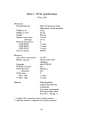
Table 1: DPM specifications ............
62
Table 2: DPM connector and cable specifications.
63
Table 3: DPM parts list . . . . . . . . . . . . . . .
64
List of Figures
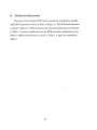
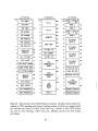
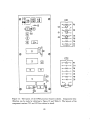
Fig. 1.
The DPM as confgured for deployment.
50
Fig.
DPM hardware block diagram. . . . . .
51
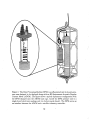
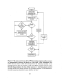
Fig. 3.
DPM communication and control flow chart
52
Fig.
Schematic diagram of the ADCM data stream
53
Fig. 5.
Contents of the ADCM header .
54
Fig.
Contents of the ADCM leader
55
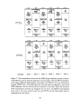
Fig. 7.
IOEB transmission scheme. .
56
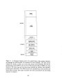
Fig.
8.
Contents of DPM output array
57
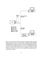
Fig.
9.
Schematic of DPM test configuration
58
2.
4.
6.
Fig. 10.
Expected output from DPM test run
59
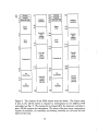
Fig. 11.
DPM board layout .
60
Fig. 12.
DPM schematic . .
61
ii
1 Introduction
1.1 Background and motivation
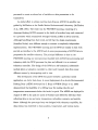
The desirability of data telemetry from remote, unmanned sites such as deep
ocean buoys has been recognized for some time, and several programs at the
Woods Hole Oceanographic Institution (Frye and Owens, 1991) and elsewhere
have helped to develop this capabilty. Much of the work to date has concentrated
on the telemetry of a limited set of data or status parameters, with little or no
data processing or compression. Although more sophisticated systems are being
developed (Frye and Owens, 1991; Irish et al., 1991), in some cases the
telemetered information from a complex sensor is only suffcient to provide an
indication of instrument status. As instrumentation becomes more complex, and
as information from multiple instruments is combined, the data rate exceeds that
which can be transmitted via conventional means (e.g., Service Argos). By
developing a telemetry interlace module with data processing capability, it is
possible to recover an intellgently composed subset of information from high data
rate instrumentation systems deployed on a drifting or moored platform.
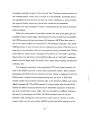
Tils report describes the development of a Data Processing Module (DPM)
for use with acoustic Doppler current meters (ADCMs). ADCMs produce
prodigious amounts of data in comparison to traditional oceanographic
instrumentation like the meteorological sensors and single point current meters
discussed by Frye and Owens (1991). During a deployment where a high degree of
temporal and spatial resolution is required, the ADCM may generate as much as 1
Kbyte of data per min. Internal recording capacity of up to 40 Mbyte allows tils
data to be archived, but the low throughput of satellte telemetry systems like
Argos (approximately 1 bytejmin) make it impossible to transmit the complete
data set. In order to be practical for real-time telemetry, the raw data must be
1
processed to create a reduced set of variables or data parameters to be
transmitted.
An initial effort to obtain real-time data from an ADCM via satellte was
guided by McPhaden at the Pacific Marine Environmental Laboratory (McPhaden
et al., 1990; 1991). The result was the PROTEUS mooring, consisting of a
downward-looking ADCM mounted in the bridle of a surface buoy, and connected
to a processor which transmitted averaged velocity profiles at 24 hr intervals.
Although benefiting from their work, we felt that the design requirements
(described below) were different enough to warrant a completely independent
implementation. The PROTEUS mooring and the DPM are similar in that both
provide an interface to the ADCM and do some pre-processing of ADCM data in
preparation for satellte telemetry. The principal difference is that on the
PROTEUS mooring one microprocessor handled both ADCM data processing and
telemetry while the DPM processes the, data and offoads it to an external
telemetry controller. The design of the DPM as a self-contained, addressable
module allows a telemetry controller to collect and transmit data from many
different sensors by interrogating each in turn.
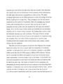
The development of the DPM was geared towards a particular initialapplication, an Arctic data buoy. A recent deployment of an Arctic Environmental
Drifting Buoy (AEDB) developed by S. Honjo of WHOI (Honjo et al., 1990)
demonstrated the feasibility of a drifting buoy for making velocity and
temperature measurements below the Arctic ice pack. The AEDB was deployed in
August of 1987 in the pack ice north of Svalbard and drifted for 255 days while
collecting data on ice and water temperature, subsurface currents, and particle
fluxes. Although the prototype buoy was designed with telemetry capability, the
data stream was restricted to buoy position, temperature, and various status
2
parameters. Information from the sub-surface instruments was not available until
recovery.
A second-generation Arctic drifter, the Ice-Ocean Environmental Buoy
(IOEB), has been developed to succeed the AEDB. The IOEB incorporates a new
buoy hull design and a meteorological package in addition to sub-surface
instrumentation similar to that deployed on the original buoy. Plans for the IOEB
call for the data from both surface and sub-surface sensors to be made available to
an Argos satellite transmitter housed in the surface floatation element. This
strategy allows the status of the buoy to be monitored more closely during the
deployment and wil give immediate access to the data regardless of the fate of the
drifter. Each IOEB wil carry an ADCM, and both ADCMs wil be equipped with
a DPM to allow the sub-surface current data to be relayed via satellte to a shore
based station along with surface meteorological data and buoy position. The
purpose of the DPM is to serve as the interface between the ADCM and an Argos
telemetry system ~n the IOEB ald to provide a manageable subset of processed
ADCM data for transmission.
1.2 Design requirements
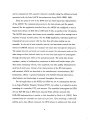
The DPM packaging specification called for a self-powered, stand-alone unit
in its own pressure case. In a typical deployment, the DPM would be attached to
ADCM load cage (Fig. 1) or on the mooring line within a few meters of the
ADCM. The power requirement was a battery supply suffcient for deployments of
6 to 9 months. Underwater cabling would provide the communications link
between the ADCM and the DPM, and between the DPM and a telemetry
controller. The communication requirements were set by the input and output
devices; the DPM was designed to process ADCM data in a manner completely
transparent to the instrument itself (i.e. requiring no modifications to the ADCM)
3
and to communicate with a generic telemetry controller using the software protocol
associated with the Serial ASCII Instrumentation Loop (SAIL; IEEE, 1985).
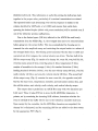
From the point of view of the DPM there are three important characteristics
of the ADCM: The communication protocol, the data stream, and the sample
interval. For the application described here, the ADCM was configured to send a
binary data stream via EIA-423 at 1200 baud (8 bits, no parity) every 15 minutes.
The ADCM data stream, also known as an ensemble, consists of an average over a
sequence of many acoustic pulses. For the IOEB application, individual pulses are
transmitted once per second, with the data from 4G pulses making up one
ensemble. At the end of each ensemble interval, the instrument records the data
stream to EPROM memory and transmits the same data through the serial port.
The sample interval and serial port enable are preset; the instrument sends out the
data strings at fixed intervals based on its own clock and cannot be interrogated
through the serial port while in the operational mode. The serial data stream
contains a variety of configuration parameters in leader and header arrays, plus
data arrays containing velocity, echo amplitude, and data qualty information for
each bin of each beam. Details of the characteristics of the RD Instruments
self-contained ADCM are described in the manufacturer's documentation (RD
Instruments, 1991a). A general familiarity with ADCM technical information,
data formats, and terminology is assumed throughout this report.
For the application on the IOEB, the DPM was not to communicate directly
to an Argos Platform Transmit Terminal (PTT), but rather to a telemetry system
consisting of a controller, PTT, and antenna. The controller interrogates the DPM
over an EIA-485 loop at 9600 baud using the SAIL software protocol (the
SAIL/485 i:qplementation is similar to that described by Park et ai., (1991)). Data
requests from the controller are made once per hour. Upon receiving a valid SAIL
address and a data offoad command, the DPM echoes its address and then sends
4
an ASCII-Hex data stream to the controller. Since the timing between the
ADCM, the DPM and the controller is arbitrary, the DPM must be able to service
a SAIL data request at any time, even when actively communicating with the
ADCM or processing data.
The difference in ADCM data output and Argos PTT throughput determines
the required data reduction. The 719 byte data stream and 15 min ensemble
interval chosen for the IOEB implementation give an effective data rate of about 3
kbytesjhr from the ADCM. The maximum throughput for Argos is in the range of
60 bytesjhr, giving a target for data reduction of at least a factor of 50. For the
IOEB deployment, a throughput of only 17 bytesjhr was available for the ADCM
data, so that data reduction by about a factor of 170 was necessary. A set of
processing routines written in the C programming language, and used previously
for laboratory analysis of ADCM data, was implemented on the DPM
microcontroller for the purpose of data reduction.
Section two of this report provides a general description of the DPM, with the
discussion separated into sub-sections on hardware, communication and control,
and software. Four appendices provide more detailed information about the DPM
and its use. Appendix A describes a procedure for testing the DPM in the lab and
Appendix B describes the deployment procedure. Appendix C is a complete
listing of all software used with the DPM. Appendix D provides technical
information in the form of tables and figures.
2 Description. of the DPM
2.1 Hardware implementation
The DPM hardware layout is sketched schematically in Figure 2. The heart
controller with 32k of external RAM,
of the electronics is an Intel 87C51FC micro
5
\ .
an external, opto-isolated UART for EIA-423 communication with the ADeM,
and an EIA-232 to EIA-485 converter for communication with a telemetry
controller. A "watchdog" timer circuit implemented in hardware is used to reset
the microcontroller in the event of firmware or communication errors. The power
system consists of two battery packs and a switching regulator. The principal
system components are discussed in turn below. '
The Intel 87C51FC microcontroller was chosen for the DPM application for a
number of reasons, the most significant of these being that all the necessary
development tools were available to ensure that 'c' code for ADeM processing,
developed for mini-computers, could easily be ported to the 87C51. In the
addition to this the controller has many other desirable features such as: low
power consumption, an idle mode, 32 kbytes of internal EPROM, 256 bytes of
internal RAM, an internal UART, and 3 internal 16 bit timers. To keep power
consumption low, the micro
controller is clocked by a 2.4576 MHz crystal and the
UART crystal is 1.8432 MHz. As currently configured, the DPM uses
approximately 23 kbytes of external RAM for data storage, so a 32 kbyte part was
used. Since the microprocessor is running at a relatively low clock rate, a 150 ns,
low power RAM was selected.
The external National Semiconductor NSC858 U ART was selected because of
its low power consumption and pin controllable power down mode. In this
application the UART is left powered down for the majority of the time to
conserve power. The port is set up to receive data only, and is shut down for 14
minutes of the 15 minute period between ADCM sampling intervals. This part
was abruptly discontinued by National Semiconductor in early 1991; there is no
pin-for-pin compatible replacement. Other similar U ARTs are available, but their
use would require both hardware and software modifications.
6
The DPM communicates with a telemetry controller via an EIA-485 link that
uses SAIL software protocol. Tils was accomplished by using a Maxim RS-485
transceiver in conjunction with the microcontroller's internal U ART. The Maxim
part was selected because of its very low power consumption (1.3 mW typ.) and
guaranteed EIA-485 performance. This part on the DPM is always enabled so
that the module wil respond to its SAIL address at any time.
The watchdog timer circuitry in the DPM is used to provide a power-up reset
pulse and to reset the micro
controller if program execution fails. When power is
initially applied to the DPM, pin 9 (reset) of the 87C51 is held high for
approximately 100 ms, after which it is brought abruptly to ground. This provides
the negative going edge (after the supply has stabilzed) that is required to
properly reset the microcontroller. The timing for the watchdog is generated by a
low frequency R-C oscilator that is divided down to approximately 32 minutes
(greater than two sampling periods for the ADCM). If the microcontroller does
not regularly reset the clock diyider, indicating a firmwar~ error condition caused
by either a lack of incoming ADCM data or a glitch in program execution, a
power-up reset pulse wil occur.
RD Instruments warns óf a corrosion problem that occurs when ADCMs are
used with an external serial device. To avoid this, the ADCM data lines must be
electrically isolated from the external device. The design requirements of the
DPM dictated use of a micro power isolator capable'.of data rates up to 9600
baud. A quick look at readily available off-the-shelf components (their power
consumption in particular) led to the decision to build an isolator from discrete
parts. A spectrally matched, high speed infra-red LED and photo diode were used
in conjunction with a discrete current limiting circuit and a micro power
operational amplifier to make the isolator. Tests showed that although the circuit
could be made to
operate at 9600 baud data rates, it was much more tolerant of
7
changes in the EIA-423 levels and to temperature fluctuations when biased for
1200 baud operation. An added advantage of tils 1200 baud configuration was
that the isolator performed well over such a wide range of signal levels that it
could be driven directly from a serial port on a PC. Since ilgh baud rates were
not required to handle the 719 bytes of ADCM data at 15 minute intervals, the
more robust and versatile 1200 baud confguration was implemented.
The DPM is equipped with two, 7 "D" cell alkaline battery packs. Tils
provides a nominal 10.5 V source with a 28 ampere-hour capacity. De-rating the
batteries to 66% of capacity to accommodate their degradation at low
temperatures and to allow for some safety factor leaves the DPM with a working
capacity of 18.5 ampere-hours. Design goals were to provide the DPM with a
service life expectancy of approximately 9 months given the duty cycle
appropriate for the IOEB deployment.
The function of the voltage regulator is to convert the battery voltage to a
constant 5 volt supply
for the DPM. The Maxim MAX638EPA switching
regulator was chosen for its high conversion effciency and small size (low
associated parts count). Bench tests showed that the configuration used in the
DPM would function at 75% to 92% effciency over the full range of expected
operating conditions. The wide range of effciency is due to load conditions that
vay from 2-30 mA, a.nd from an input (battery) voltage range that varies from
11-6.5 V (6.5 is the minimum input voltage allowed for regulator operation).
2.2 Communication' and cóntrol
The DPM communicates serially with the ADCM over an optically isolated
EIA-423 link and with a telemetry controller via EIA-485. The 1200 baud
EIA-423 communications link is accomplished in the DPM by an NSC858 DART
which provides a data ready pulse to the 87C51 microcontroller's external
8
interrupt 1 pin. The 87C51 on-chip serial port services the 9600 baud EIA-485
communicàtion link. Both channels use 8 bits and no parity.
A flow chart of DPM communication and control is shown in Figure 3. The
DPM is initially powered up by use of an external control line (a shorting plug) or
may. experience a power-up reset due to the watchdog timer. In normal operation
the DPM resets the watchdog timer every 15 minutes, after receipt of each
ensemble from the ADCM. This prevents the timer from reaching its 32 minute
trigger. In the event that the timer is not reset during a 32 minute period, the
watchdog circuit wil provide a pulse to reset the DPM. Upon reset, the DPM
restars the firmware, reinitializing all variables and zeroing the output buffers.
Thus, a data stream of all zeros from the DPM in response to a SAIL query
indicates that a reset has occurred.
controller is put into a low power
In order to save power, the 87C51FC micro
idle mode ~henever it is not processing data or servicing serial, external or timer
interrupts. The microcontroller exits idle mode when it receives an interrupt, so
the telemetry controller can address the DPM over the EIA-485 link at any time.
The NSC858 U ART is turned off by the microcontroller directly after receipt of a
complete 719 byte ensemble from the ADCM. WilIe it is off, characters sent by
the ADCM would not trigger an external interrupt and therefore not be received
by the DPM. However, the UART is turned back on 14 minutes after it is turned
off, in response to the micro
controller's internal timer 1 interrupt routine. Since
ensembles are sent every 15 minutes by the ADCM, all of the ADCM data is
received.
A communications interrupt may be either the EIA-423 data stream from the
ADCM or an EIA-485 SAIL command from a telemetry controller. If incoming
ADCM data has the proper character count (719 bytes), it is sent to an
"unpacking" routine where the .packed binary data stream is decoded. An
9
incomplete ensemble (at least 1 byte, but less than 719 bytes) causes a timeout in
the communications routine and is counted as a bad ensemble. Ensembles sent to
the unpacking routine which do not have the correct checksum, or do not contain
the expected header values, are rejected and counted as bad ensembles.
Otherwise, the "good ensemble" counter is incremented and the data is stored for
later processing.
When the total number of ensembles received (the sum of the good and bad
ensemble counters) equals eight, representing two hours of data from the ADCM,
the DPM processes the data and stores a 68 character ASCII-Hex data array in
one of two output buffers for transmission to the telemetry controller. The double
bufering scheme is used to ensure that an existing output array, which has not yet
been sent to the controller, wil not be corrupted by newly processed data. Witiln
each bufer the output array is arranged in two halves, an "even half" containing
data for the even depth bins of the ADCM profie, and an "odd half" containing
data for the odd depth bins (the details of the output array contents are discussed
in Section 2.3).
Two telemetry controllers, with independent PTTs and Argos antennae, are
used on the IOEB to provide a robust data transmission scheme. Each controller
interrogates the DPM at 2 hour intervals, but their timing is staggered so that the
DPM receives a request for data approximately once per hour. A SAIL data
request consists of an attention character (#), a two character address, and ~ data
offoad command (R). The DPM responds to a data request with an echo of the
address and offoad command followed by 34 ASCII-Hex characters of data from
the most recently filled output buffer. The two controllers use different addresses
(40 and 41) to interrogate the DPM. The DPM considers either of the two
addresses valid, sending the even half of the output array in response to a data
request which uses the even address (#40R) and the odd half in response to one
10
which uses the odd address (#41R). Thus, transmission of the full DPM output
array is split over two independent telemetry systems. The data in the two halves
of the output array are arranged so that either half alone provides useful
information.
2.3 Data processing
The DPM processing .routines were developed from programs used to analyze
ADCM data from the Arctic Environmental Drifting Buoy deployment
(Plueddemann, 1991). There are two principal processing tasks, "unpacking" the
binary ADCM data stream for each ensemble and reducing the. data after eight
ensembles have been unpacked. For the IOEB application the ADCM data stream
is 719 bytes long and contains a header and leader, plus velocity, echo intensity,
percent good, and status information for each beam (Fig. 4). Spectral width is
not r.ecorded. The unpacking step consists of decoding the packed binary ADCM
data stream and fillng a floating point array with the decoded, scaled data. The
majority of the data reduction is accomplished by eliminating non-essential data
and averaging the remaining data in depth and time. Some additional benefit is
gained from the creation of summary error and status parameters and judicious
scalng based on expected data values.
Upon receiving a 719 byte ensemble from the ADCM, the controllng program
passes the array to the unpacking routine. The fist step in the unpacking routine
is to compute the checksum for the complete ensemble and decode the header.
The checksum computed in the unpack routine is compared to the checksum sent
with the ensemble. The size of each of the data arrays is extracted from the
header (Fig. 5) and checked against the expected array sizes. Any errors found
during these checks result in a flag being set to indicate a communication error.
The associated data ensemble is counted as a "bad ensemble", it is not stored and
11
wil not be included in the. averaging step. Ensembles wilch pass these checks are
processed further; the leader data (Fig. 6) is extracted and stored (except for the
CTD and bottom track variables, since these functions are not used), and the four
data arrays are decoded and stored.
After eight ADCM ensembles have been received, the controllng program
calls a sequence of routines that perform several processing steps along with error
checking and averaging. The first processing step is to document the status of
ADCM operation using information from the leader and the percent good aray.
The Built In Test (BIT status; RDI, 1991a) code from the leader is used to set
two flags, one for beam frequency errors and one for transmitter current errors.
The percent good information is combined into a single good/no-good status bit
for each averaged bin. Data in a given bin is generally considered to be of poor
quality if the percent good value is less than 25. The status bit is set if percent
good values less
than 25 occur in more than ten percent of the samples in the,
depth-time averaging interval.
The next processing step is time averaging of the leader data. This consists of
a simple arithmetic average over the number of unpacked ensembles in the storage
arrays. Under normal conditions 8 ensembles wil have been unpacked and stored
at the end of a two hour period. If communication errors have occurred, there
may be fewer than 8 ensembles to process. There are 14 leader values included in
the averaging step: time in decimal days, number of ADCM bins, ensemble
number, BIT status, x-axis tilt, y-axis tilt, heading, temperature, high voltage
level, transmit current level, low voltage level, and the standard deviations of
x-tilt, y-tilt, and heading.
The major processing task involves manipulation of the velocity and echo
amplitude data, recorded by the ADCM in beam coordinates, to produce
depth-time averaged arrays in earth coordinates. For the IOEB application a 16 m
12
transmit pulse was used and 40 eight-meter bins were recorded. Note that since
the transmit pulse sets the fundamental vertical resolution of the measurements,
the eight meter bins represent oversampling by a factor of two. The depth
averaging implemented for the IOEB deployment is a three bin average of the fist
30 bins, resulting in 10 averaged bins. Time averaging is over the 2 hr interva
represented by the sequence of 8 ensembles. Before the averaging step, however,
several other processing tasks are executed. First, the tilt data is used to
interpolate the slant velocity and echo amplitude for each beam onto standard
depths. Next, the four beams of slant velocity are combined into two horizontal
velocities and two vertical velocity estimates. The heading data is used to rotate
the horizontal velocities into earth coordinates. The mean of the two vertical
velocities and the mean of the four beams of echo amplitude are computed during
the averaging. Thus, the output of this processing step.is 4 ten-bin arrays
containing depth-time averaged values of east velocity, north velocity, vertical
velocity, and echo amplitude.
The final step in the processing is to pack the status flags plus the averaged
leader and velocity data into an output buffer for transmission to a telemetry
controller. As discussed above, there are two telemetry controllers on the IOEB
which request data from the DPM using two different SAIL addresses. Between
the two controllers the DPM is interrogated once per hour and the full output
aray, representing a two hour average, is sent in two halves. It was decided that
the hourly transmissions would consist of a header plus status and velocity data
for half of the depth bins. The header is repeated for each transmission, but
alternating even and odd depth bins are sent in response to the alternating SAIL
addresses. A combination of a count bit which alternates between 0 and 1, and an
even (0) and odd (1) bin flag are used to keep track of what has been sent
(i.e., four successive transmissions would have a (count, even/odd bin) sequence of
13
(0,0) (0,1) (1,0) (1,1)). This information is useful for putting the half-arrays back
together in the proper order, particularly if occasional transmissions are missed.
The repeated header and alternating even-odd bin sequence is similar to the
scheme described by McPhaden et ai. (1990) and ensures that usable data
spanning the desired depths (albeit with poorer resolution) wil be received even if
one of the telemetry systems malfunctions.
Due to the limited space (135 bits) allotted to the ADCM for each hourly
transmission from the IOEB (Fig. 7), the averaged data had to be reduced further
before going into the output buffer. This was accómplished by choosing not to
transmit the echo amplitude array and restricting the output header to a subset of
the averaged leader data. The floating point horizontal velocity data is scaled and
converted into 8-bit integers, the vertical velocity into 4-bits. The first half of the
272 bit output array (Fig. 8) consists of a dummy bit, count bit, even/odd bin bit,
even-bin status array (5 bits), error flag array (4 bits), temperature (8 bits),
number of ensembles in the average (4 bits), tilt standard deviation (6 bits),
heading standard deviation (6 bits), even-bin east velocity array (40 bits), even-bin
north velocity (40 bits), and even-bin vertical velocity (20 bits). The second half
of the output array (Fig. 8) contains the same count bit, the opposite even/odd
bin bit, the same error, temperature, ensemble, and instrument motion data, and
the odd-bin status, east velocity, north velocity, and vertical velocity arrays.
The output data is packed into an ASCII-Hex array with two characters per
8-bit word. Thus, it takes 272 bits to store the 68 ASCII-Hex characters. A
pointer, set by examining the incoming SAIL address, determines whether the
even or odd half of the buffer wil be sent to the telemetry controller each hour.
Upon receipt by the controller, the 34 ASCII-Hex characters are unpacked, the
dummy bit is eliminated, and the remaining 135 bits are added to the data stream
for the appropriate PTT (Fig 7).
14
Acknowledgements
Many hours of useful advice were provided by E. Hobart throughout the
project. M. McPhaden kindly provided technical details of the PROTEUS
development. The initial effort on this project was supported by seed money from
the Woods Hole Oceanograpruc Institution in the form of a grant from the
Vetlesen Fund. Continued work leading to the completion of a field-ready version
of the DPM was supported by the Offce of Naval Research, Code 1122AR, under
Grant No. NOO0l4-89-J-1288.
15
References
Frye, D. E. and W. B. Owens, 1991. Recent developments in ocean data
telemetry at Woods Hole Oceanographic Institution, IEEE Journal of
Oceanic Engineering, 16(4), 350-359.
Honjo, S., R. Krishfield and A. Plueddemann, 1990. The Arctic Environmental
Drifting Buoy (AEDB): Report of field operations and results, Woods Hole
Oceanographic Institution, Woods Hole, MA, Technical Report WHOI-90-2,
128 pp.
IEEE Computer Society, 1985. IEEE standard serial ASCII instrumentation loop
(SAIL) srupboard data communication, IEEE, New York.
Irish, J. D., K. E. Morey, G. J. Needell and J. D. Wood, 1991. A current meter
with inteHigent data system, environmental sensors, and telemetry, IEEE
Journal of Oceanic Engineering, 16(4), 319-328.
McPhaden, M. J., H. B. Milburn, A. 1. Nakamura and A. J. Shepherd, 1990.
PROTEUS - Profile Telemetry of Upper Ocean Currents, Proc. MTS 1990
Conference, Marine Technological Society, 353-357.
1991. .
McPhaden, M. J., H. B. Milburn, A. 1. Nakamura and A. J. Shepherd,
PROTEUS - Profile Telemetry
of Upper Ocean Currents, Sea Technology,
- February Issue, 10-19.
Park, M. M., R. C. Singer, A. J. Plueddemann and R. A. Weller, 1991.
High-speed, real-time data acquisition for vector measuring current meters,
IEEE Journal of Oceanic Engineering, 16(4), 360-367.
Plueddemann, A. J., 1991. Internal wave observations .from the Arctic
Environmental Drifting Buoy, Journal of Geophysical Research, submitted.
RD Instruments, 1991a. Self-Contained Acoustic Doppler Profiler Technical
Manual, RD Instruments, San Diego, CA, 330 pp.
RD Instruments, 1991b. Deployment Program User's Manual, RD Instruments,
San Diego, CA, 34 pp.
16
Appendices
A. Test procedure
A test procedure meant to be used in verifying the operation of the DPM
prior to field deployment is described below. Two IBM compatible PCs, an
ameter, and various test cables are necessary for the complete test (Fig. 9). The
ammeter replaces the DPM shorting plug and is used to check current draw by the
DART and microcontroller. The procedure can be performed without the
ammeter if current checks are not desired. The PCs simulate the ADCM and
telemetry controller. The result of the test is a sequence of DPM output records
which can be compared to a fie containing the expected output. A RMK-7 to
DB-25 test cable is needed to connect the EIA-423 side of the DPM to the PC
simulating the ADCM. A program called üVERNITE.C (see Appendix C) is run
on trus PC to send simulated ADCM data transmissions to the DPM. The
program accesses a data file called DPMCCS6.BIN containing a sequence of
previously recorded ADCM binary data ensembles which have been modified to
test a variety of DPM features. A RMG-3BCL connector and cable are used to
connect the EIA-485 side of the DPM to an Acromag EIA-485 to EIA-232
converter box. A second cable with two DB-25 connectors attaches the Acromag
box to the serial port (COMl) of the PC simulating the telemetry controller. This
..
PC runs a program called TT.C (see Appendix C) which requests processed data
records from the DPM using SAIL commands.
The VSG-2BCL connector on the top end cap of the DPM is used to power
the module. A dummy plug is used to cover this connector when the DPM is not
in use. The RED color-coded shorting plug turns the DPM on by connecting the
10.5 VDC battery packs in the DPM to the input of the switching regulator. After
making the initial connection with an ammeter in place of the shorting plug, the
17
DPM should settle out, within 20 seconds, to a current drain of 2.3 mA :: 0.3 mA.
At this point the DPM UART is on and waiting for data. The DPM will stay in
this state until it receives a serial stream from the ADCM (or equivalent
simulation). The ADCM serial data enters the DPM via the XSK-7BCL
connector. The XSG-3BCL connector is the EIA-485 connection between the
DPM and the telemetry controller or controller simulator.
ADeM operation is simulated by connecting the RMK-7 to DB-25 test cable
from the DPM to the serial port (COMl) of a pe and running the test program
QVERNITE.C. The test program wil ask for a data fie to use as input. The fie
DPMCCS6.BIN should be available in the same directory as OVERNITE.C and
should be specified as the input file. The number of ensembles should be set to
144 and the time between ensembles to 15 minutes. If a mistake is made in
specifying input parameters for OVERNITE.C, reboot the computer, reset the
DPM by removing and re-connecting the shorting plug (or ammeter connection),
and stRrt again. When OVERNITE.C is running successfully, a message wil be
sent" to the screen as each simulated ADCM data ensemble is sent.
Immediately after receiving a valid ADCM data ensemble, the current draw
from the DPM wil rise to 5.5 mA :: 0.5 mA for a few seconds while the DPM
unpacks and stores the data in RAM. After receiving and unpacking the data, the
DPM goes into an idle mode in which it wil respond to EIA-485 SAIL requests
. .
from the telemetry controller, but wil not accept data from the ADCM. The
NSe858 U ART is powered down in this state and the microcontroller is idle. The
current drawn by the DPM wil drop to 1.2 mA :: 0.3 mA. The idle mode wil
continue for 14 minutes after which the UART is turned back on and the DPM is
ready and waiting for EIA-423 data from the ADCM. The current level wil
increase back to the original 2.3 mA :: 0.3 mA until another valid ADCM
ensemble is received and the data collection cycle begins again. This cycle wil
18
continue unless data is not received from the DPM at the expected 15 minute
interval (e.g., the ADCM is disconnected or inoperative and data transmissions
stop). If no ADCM ensembles are received, the DPM wil wait in the ready state
(NSe858 DART on) for EIA-423 data and the microprocessor wil be reset every
32 minutes by the watchdog timer.
Any time after the DPM is turned on (using the shorting plug or an ammeter
in place of the shorting plug), the module can be addressed via EIA-485 SAIL
commands. A 50 foot test cable with a RMG-3BCL connector on one end is
provided for this purpose. The other end of the cable should be connected to an
Acromag 485/232 converter box. The EIA-232 side of the Acromag box is then
connected to the serial port (COMl) of a PC running the telemetry controller
simulation program TT.C. (Note that TT.C is not necessary for a simple
simulation of the telemetry controller - a terminal emulation program running on
the PC with serial communication settings of 9600 baud, no party, 8 data bits, 1
stop bit can be used to send SAIL commands by hand). It should be started at
least 5 minutes, but less than 15 minutes after OVERNIGHT.C for proper results.
The TT.C program wil request a data file name to wruch it wil log the DPM
responses. TT.C wil send the first command (without the attention character #)
to the DPM within a minute after the interrogation loop is started by selecting a
transmission interval. An interval of 60 minutes should be selected. The DPM wil
respond to the SAIL data ofHoad commands #40R and #41R with an echo of the
command (without the attention character #) followed by 34 characters of data
and an ETX (ASCII 03) to end the transmission. The data wil be all zeros until
eight ensembles have been received and processed. The receipt of eight ensembles
wil take two hours from the time of the first ADCM ensemble. Since the DPM
output array is in two halves, transmitted once per hour, the response to the first
two SAIL requests wil contain zeros.
19
The processing steps initiated upon receipt of the 8th ADCM ensemble take
approximately four minutes to complete. During trus time the current drain at the
DPM wil be 6 mA :l 0.5 mA. Once the first set of eight ensembles has been
processed, the DPM wil respond to the SAIL offoad commands by sending the
processed data. If at any time after trus the DPM responds to a data request with
a string of zeros, it is an indication that the microprocessor has been reset by the
watchdog timer. A listing of the expected DPM output when using the simulated
ADCM ensembles in the file DPMCCS6.BIN is given in Figure 10 and in the file
DPMCCS6.0UT. The contents of the file created by TT.C during the test
procedure should be compared to this listing.
B. Deployment procedure
1. The ADCM and DPM should be installed in the load cage (see Fig. 1) and
the cable from the telemetry controller should be accessible at the location
. of the DPM.
2. Download the desired configuration parameters to the ADeM using the
Deployment Confguration Files provided (e.g., I198.DPF) and the RD
Instruments Deployment Program (RD Instruments, 1991b). Upon
completion of the deployment procedure, the ADCM wil be running and
sending serial data every 15 minutes. The first ensemble wil be sent
immediately following the last entry in the deployment sequence. Since the
DPM is not connected at this time, the first ensemble received by the DPM
will be 15 minutes later.
3. Remove the three dummy plugs from the DPM and store them in the
packing crate. Locate the RED color-coded shorting plug in the packing
crate. Attach the DPM XSK-7BCL connector to the ADCM XSL-20BCR
20 .
I/O connector using the two meter RMK-7FS to XSL-20CCP cable packed
with the DPM. Attach the DPM XSG-3BCL connector to the telemetry
controller cable.
4. Power up and reset the DPM by connecting the RED color-coded shorting
plug to the VSG-2BCL connector on the end cap. The DPM wil now be
running and waiting for the next ensemble from the ADCM. Note that the
fist ensemble wil not have been received by the DPM (see (2)), but it is
assumed that (3) and (4) are completed within 15 min of starting the
ADCM, so that the second ensemble wil be received.
5. The DPM can be interrogated by the telemetry controller at any time after
power-up. The fist non-zero data array from the DPM wil be obtained after
receipt and processing of eight ADCM ensembles, or 2 hrs after receipt of
the first ensemble. Since the first ADCM record is not received by the DPM,
this wil occur approximately 2 hrs 15 mIn after start-up of the ADCM.
c. Program listings
Four C-language programs associated with the use of the DPM are listed on
the following pages.
DPM.C is the main communication and processing program, written in
Franlin C, which runs on the Intel 87C51FC microcontroller in the DPM. The
compiler used was Franklin C, version 3.07, the assembler was Franklin Assembler
version 4.4, and the linker was Franklin Linker L51, version 2.7. A companion
program, PC-ÐPM.C, was written in Microsoft Quick-C and run on an IBM
compatible PC. PC-ÐPM processes data in the same fashion as DPM.C, but reads
from and writes to disk fies on the PC rather than communicating to the ADCM
21
or the telemetry controller. This version was used during development and testing,
but is not reproduced here.
OVERNITE.C and TT.C are used in the deployment simulation procedure
and allow the DPM to be exercised in the absence of the other instrumentation to
be used in the deployment. OVERNITE.C simulates the operation of the ADeM
by taking a fie of binary ADCM data and sending it serially to the DPM at a user
specified interval. TT. C simulates the telemetry controller by sending alternating
SAIL data offoad commands (#40R and #41R) to the DPM at an adjustable
interval. The data received in response is stored in a file and printed to the screen.
DPMSATOUT.C unpacks the output data array sent to the telemetry
controller, and was used during development and testing of the DPM. The
program takes groups of 34 ASCII hex characters representing alternating halves
of the output data array, combines the appropriate pairs, and then decodes the
data.
22
l'
W
4
NBEA
HAXBINS
HAXLDR
HAXENS
AVGLDR
AVGBINS
NTYPE
NRECA
0
FALSE
HAXBYTE
ENSEMBLE
UART
40
14
10
14
10
22
8
1
119
1
0
TRUE
1*
1*
1*
/*
I.
I"
1*
1*
1*
I.
.1
number of sonar beams *1
number of adcp strings to collect before
.1
processinq and moving to the output buffer *1
max I of bins per record *1
max I of values at leader to store*1
max. no. of ensembles to store "i
i of points in averaged leader "1
I of depth bins after averaging *1
I of data types (leader+vel+amp) .1
.
1* number of bytes in adcp ensemble *1
1* value tor use with timer 1 flag .1
I
!loat Idr (MAXLDR) I
float vel (NBEAH) lHAXBINS) I
I" subset of leader data *1
1* velocity array *1
typedet struct stored I" unpacked data structure "1
I" declaratIon of arrays and structures "I
unsigned char unp err: 1* number of errors from unpack routine .1
unsigned char badrec: I" number of short or bad records "1
data int itcount: 1* variable to count timer 1 iterations "1
0(14), buffl(74J: 1* processed data output buffers/ptr */
char "outbuff, buff
unsigned char chcount: 1* .count of ASCII hex chars to send via SAIL *1
bit attention, addressed, offload, oddeven, intschk, nosleep: I. fla98 .1
bit tlurang, tlerang, altflag, acflag, buffbit, digl:
unsigned char ddata(HABYTEI, " data ddptr: I" incoming ADCP data bUffer/ptr *1
unsigned char nproc: 1* count of good adcp data ensembles sent "I
Ilnclude .(reg51f.h)o
linclude .(math.h)o
Ide fine
Ide fine
Idefine
IdefIne
IdefIne
Idefine
Idet1ne
Idaflne
Idefine
Idefine
Ideflne
Ideflne
Idefine
I.. The terms record and ensemble are used interchangeably *1
1* 1.8432Hhz. *1
1* buffering is used and odd and even layer data is sent in .1
1* response to different SAIL addresses. The microcontroller*1
1* is clocked by a 2.4576Hhz crystal and the UART crystal is *1
/* verter on the microcontroller's serial lines. Double *1
/* a 32 minute hardware deadman timer, and an EIA-485 con- *1
1* an NSC 858 UART for EIA-422 communication with the ADep, *1
1* Intel 87C51FC microcontroller with 32k of external RA, *1
1* a SAIL request over an EIA-48S channeL. It runs on an *1
I. The DPH is a data processing module which processes ADCP * 1
I.. ensembles and provides an ASCII Hex string in response to * I
float Idr (AVGLDRI;
!loat Jan (3) (AVGBINS);
!loat amp IAVGBINS i ;
(
void
void
void
void
void
void
void
void
void
void
void
void
void
void
void
void
bit
void
void
dead (void) ;
prepack (buff 0) :
prepack (butfl);
not dead 0 :
buff 010) - '4'1
buff 0(1) - '0'1
AOSINIT 0:
unp err - 0;
NSCiNIT li I
aVg.error - OxOO:
badrec - 0;
ddptr - ddata;
nproc - 0;
buffbit - 0;
oddeven - 0:
tlurang - TRUE;
tlerang - FALSE;
nos leep - FALSE;
offload - FALSE:
point to start of ddata buffer .1
initialize number of strings from adcp */
1st time send from buffO, repack into bufn *1
initial1ze bad record counter "1
initialize global error flag *1
initialize unpack error indicator "1
initlalize UART .1
initialize 8751 serial communication "1
I. zero the ASCI I hex output butfers .1
I" initialize the deadman timer .1
1* set up buffers to echo address and offload and *1
1*
1*
1*
I"
I"
1*
I.
I.
1* sleep after loop unless partial record timeout .1
I. start out with UART enabled'.1
1* haven't used timer 1 for ensemble time yet *1
I. initialize SAIL bit flags .1
prepack (unsigned char *bfptr) 1
not
err (uns igned char nproe);
uarton (void);
janus echo (unsiQned char nrec):
repack (unsigned ehar *bfptr,blt count, unsiQned char nrp):
uartoft (void);
pc_ieader (unslQ1ned chilr nrec);
unp 1 (unaiQlned char irec, unsiQned char .e);
qoodnight (vold);
ttdelay (voldl;
uonidle (voidl;
aclock (void);
etimer (void):
process (char. frombuff, char * tobuff);
iendptt (char 6 buffer);
ADSINIT (voidl; ,
NSCINIT (void I I
checkaddr (void);
attention - FALSE:
addressed - FALSE;
mainll
extern
extern
extern
extern
extern
extern
extern
ext ern
extern
extern
extern
extern
extern
extern
extern
extern
extern
extern
extern
averaged avg:
unsigned char sb(AVGBINS);
unsigned char error:
) averaged:
l
stored stor (NRECA); 1* array of structures of unpacked data .1
typedef struct averaoed 1* record-averaged data structure .1
I.. Franklin Linker (LSl) version 2.7 *1
stored:
float amplNBEAHI (HAXBINSli
I" echo amplitude array .1
!loat qd (NBEAH) (HABINS I i
I" percent good array .1
unsiqned char st (16) (HAXBINS); I. bit atatus array "1
1* Hain routine for ADCP DPH *1
I. Franklin Assembler version 4.4 .1
I. Franklin C compiler version 3.01 *1
/* Hay I, 1991 */
/* by Robin Singer .1
/* DPH.C "I
t.t
uartoff ():
buff
0(37) - '4
(1)) I. If so, expect 716 more 1200 baud chara .1
I
I
(uñp err--Ol)
tlerang - FALSE;
nosleep - TRUE;
1f (tlerangl
badrec l-1;
I. reset the deadman timer .,
1* reset this flag .1
1* we'll stay on till things qet right .1
1* or bad ensemble counter .,
I. alarm clock on for 14 minutes - when it .,
I. rings the ISR sets t1uranQ , puts UART on .1
I. UART alarm rang flag off .1
if ((nproe + badrec) -- NRECA)
I. Have we received a full suite of adcp ensembles to process? .1
acloek () ;
aetlag - UART:
tlurang - FALSE;
I. get ready to turn UART off until another ensemble expected .1
I. by setting up the UART wakeup timer 61
notdead () :
I
l
else
nproe++; - I. increment good ensemble counter .1
1f1(lt1erangl"
unp-l (nproc,'unp err); I. unpack the data from the adcp .1
ddptr - ddata: I. reinitialize the incoming data buffer *1
TCON ,- OxBF; 1* disable timer 1 .1
nosleep - FALSE; I. we'll sleep unless this was a timeout .1
unp err - FALSE; I. reinitialize error flag .1
1f (acflag--ENSEMBLE)
1f I (ddptr -- ,ddata (HABYTEIl II ((ddptr.'ddata (0 il" (tlerangl I)
I
I. Have we either received a whole ensemble string from the .1
I. adcp or timed out after receiving only a partial ensemble? .1
1* it it rings, t1erang qets set to TRUE *1
I. in the timer 1 interrupt routine .1
aclock n; I. set to ENSEMBLE (rin98 in about 40 seca) *1
acflag - ENSEH"BLE; I. ao call the alarm clock routine with actla; *1
I I. which should take about 6 aecondsa *1
if (ddptr--'ddata
I. Haye we received the Urst data byte from the adcp '1 .1
Intschk - TRUE; I. before sleeping we must prove that .1
/6 we've been throuQh this whole loop "1
/6 interrupt routines set intschk to FALSE .1
while ClI
(
buff1(3BI - '1'
bulf1(39) - 'R'
buffl(371 - '4'
buffO(3B) - '1'
buff 0(39) - 'R'
.goodnight (); 1* otherwise, low power - idle with the UART off .1
else
uonld1e () i I. Idle with ths UART on .1
1f ( It 1 urang) II (noBleepl)
1* If UART alarm clock ranI) or a timeout occurred *1
I. If we've been throul)h the whole loop *1
avq.error - axOOII. relnltlallze olobal error flag */
ddptr - ddata; I. relnltlallze the Incomlnl; data buffer *1
tlerang - FALSE; .1* 1n case we were out of sync with ADCP *1
npeoe - 0; /* relnitiallze good ensemble counter */
badrec .. 0; /* reinltlallze bad ensemble counter */
I. and beam-avQ echo ampiitudes "1
outbult - buffblt 1 butfO : buff!; /* where to put processed data .1
repackCoutbuff+3,buffblt,nproc)¡ 1* a8 ASCII Hex chars for ARGOS .1
buffblt-(Ibuffblt)i I. switch buffers - the new data 1s ready .1
If (1ntschkl
I
I. uart off while we process .1
I. store error/statu. Info for repack "I
pc leader (nproc) ; I. compute average leader values "/
jañus_echo(nproc) ; /" compute average janus velocities .1
err (nproc):
buff1(2) - 'R'
bufflll) - '0'
bulfO(21 - . R'
buffl (0) - '4'
~
01
I" The Timer 1 ISR (mttimint.a51) will increment itcount and reset the *1
I. has passed, in which case It turns the uart on and sets the tlurang .1
1* tlaC) to TRUE ...or... (2~ acll.o equals i and 144 Iterations labout *1
1* 40 seconds) have passed In which case it set. the tlerang tlaC). *1
1* timer unle.s: (1) acllaQ equals 0 and 2625 Iterations (l4 mInutes) *1
itcount
- 0; .
IE 1- axae; 1* enable timer 1 interrupt .1
TeON 1- Ox40; I" set the timer 1 run control bIt to turn timer 1 on .1
TLl - Oxai:
THI - OxOO; I" 16 bits at 2.4" Qives .3 SBC *1
THOD - OxlO; I. timer 1 to timer mode 1 116 bits) .1
1* delay a bit .1
ddptr - ddata; I. when we wake up we will bo ready for a new enemble .1
peON 1- OxOl; I. go into idle *1
UON - FALSE; I" power down the uart by clearin; Pl.1 .1
for (n-O; n-(PDLAY; n++1
unsigned char n;
UON - FALSE;
tor In-O; n-(PDLAY; n++)
unsigned char n;
I
for (n-O; n-(PDLAY: n++1
unsigned char n;
void uonidle (voidl
1* delay a bit .1
I. leave UART on but put micro into idle .1
t
void uartol! (void)
I. power down NSC but leave 8151 on *1
I
I. end of deadman reset pulse *1
I
.bufptr++ - Ox30;
for (n-O; n-(BUrFLEN; n++)
.bufptr"'+ - , 4' ;
"bufptr++ - , 1';
"bulptr++ - , R';
.bufptr++ - Ox30;
for (n-O; n-(BUFFLEN; n"'+)
*bufptr++ - '0';
*butptr++ - 'R';
*bufptr++ - , 4' I
unsiqned char n;
void prepack (unsioned char *bulptr)
I" InitIalIze output bulters with SAIL echo and zeroes *1
DEADMAN - 0;
for Idelay-DHDLAY; delay.O; delay-oj
Int delay;
90odni9ht (void)
DEADMAN - 1; 1* send reset to deadman circuit (4060) *1
l
voId notdead (voldJ 1* prevent. hardware reset by resetting 4060 * I
(
void
-(math.h:.
cre9Slf .h'
DEADMA - Ox90; 1* Deadman Timer (4060) Reset Line *1
34 I. lenQth ol SAIL output data string *1
UON - axil: I" NSC UART on pIn "I
UART alarm clock routine "I
sets up the timer to wake up the NSC UART In time to listen *1
for the next ADCP ensemble .1
also used for timeout clock in case a partial ensemble or .1
stray characters arrive at the UART *1
void aclock (void)
I.
1*
I.
I.
I.
peON 1- ax01: I" C)O Into idle "I
I. power down Nse and then put 8151 into idle mode .1
.include
.include
.bit
.bit
'deline DMDLAY
'define BUFFLEN
a
Idenna FALSE
.daUhe PDLAY
100 I. power down delay to wait lor stop bit .1
450 I. deadman timer reset delay "I
1
'deCine TRUE
extern unsi;ned char * data ddptr;
extern unsigned char ddata (J;
extern data Int itcount; 1* Iteration counter for UART sleep interval *1
extern int tcount; I. iteratIon counter for ensemble receive timer .1
1* Franklin Linker (L5ll version 2.7 "I
I" Franklin Assembler versIon 4.4 *1
/" Franklin C compiler version 3.07 *1
/* Hay 15, 1991 "I
/* by Robin Singer "/
1* dpmfns.c *1
t0)
HAXBYTE
NRECA
HAXBINS
HAXLDR
NBEAH
AVGLDR
AVGBINS
NBINA
14
10
3
4
14
40
8
119
max number of byt.. per record (aerial input) */
number of record. to accumulate */
number of depth bIns per record *1
miX number at values of leader to store .1
number of 80nar beams used in calc *1
number of leader values averaged and stored .1
stored;
averaged;
unaloned char Ib(AVG8INSJ;
unsigned char error;
float Idr (AVGLDRJ;
float jan (3 J (AVGBINS);
float amp(AVGBINSI;
extern float eab(4J (l0);
extern float dt threih(NTYPEJ;
extern float dz:thresh(2*NBEAI;
extern averaged avq;
extern stored stor(NRECA);
l
subset of leader data .1
velocity array *1
echo amplitude array .1
percent Qood array .1
bit statuii array *1
I. stored data atrucure .1
I.
I.
I.
1*
1*
I. beam and bin averaged echo amp *1
1* dt threshold storage butter .1
1* dz threshold storage buffer 0/
I. averaged data array *1
1* array of unpacked records *1
I. averaged leader array .1
I. averaged janu8 velocity array *1
I. averaged echo amplitude array *1
I. calc statui using percent good .1
I. error code per output cycle .1
I.struct of data averaQed over NRECA t of records.1
unsioned char .t (l6J (HAXBINSJ;
float OdlNBEAJ (HABINSJ;
float Idr (HALDRJ ;
float vel (NBEAM) (HAXBINSI;
float amp(NBEAM) (HAXBINSJ;
typedef .truct averaged
I
typed.f .truct stored
1* input data buffer .1
I. no. of data type. Ueaderlvelocltylamplltudel.1
1* multiple at standard dev. tor threshold set *1
and dz functions .1
I. numr of depth bins afer averaging *1
1* no. ot bins averaoed(MAXBINS div. by AVGBINS).I
1*
1*
1*
1*
1*
1*
extern unaloned char ddata (HAXBYTEJ I
I. for dt
'det1ne NTYPE
22
'deflne SD_FACTOR
3
'det1ne
'det1ne
'det1ne
'define
'det1ne
'det1ne
'det1ne
'det1ne
.1
This header tile contains symolic constanta and external data
atructure declarations that are used in the functions called by
the dapro/dpm program.
I. dapro. h
t-i
transmit current scal. factor Clow power)"/
echo amplitude conversion factor .1
std døv Bcale factor for pitch and roll */
std døv Bcale factor tor heading .1
Bcale for converting hours to decimal day */
I. echo amplitude conversion factor to dB .1
eo
160
160
0
49
240
63
2
14
I.
I.
1*
1*
1*
1*
I.
I.
I.
81z8 at binary header .1
81ze of checksum *1
no. byte. in long leader *1
no. byte. In short leader *1
no. bytes of velocity data per record
no. bytes of spectral width. data .1
no. bytes of echo amplitude data .1
no. bytes of percent c;ood data .1
no. bytes of status data per record .1
I.
I.
I.
I.
I.
I.
I.
byte. 1n the
byte 81z8 of
byte 8ize ot
byte slze of
byte size of
byte size of
byte size of
record .1
leader *1
velocity data .1
spectral width data .1
echo amplitude data "I
, good data .1
status data .1
double ppow (double baae,double n);
unsic;ned short comb (unsigned char IDsb, unsigned char lsb);
unsigned short comb" (lnt which, unsigned char by, unsigned char nibble);
int splltb(unalgned char by, unsigned char "lan, unsigned char "msn);
I" bit manipUlation subroutines and working variables .1
unslC)ned short at:.z;
unslc;ned short c;d šz;
unsigned sh.ort apw - az;
unsic;ned short amp - 8Z;
unsiQned short iead 811
unsic;ned short vel az;
i nt M,axbyt..1
I. input ilrray .lze8 .1
char year(5); 1* at.rtinc; year *1
1* deployment dependent parameter-s .1
BINHD ~iz
CHCKSII_SIZ
LONG LD
SHORT LD
VEL SZ
SPW-SZ
AMP-SZ
GD 5Z
ST~)Z
I. chanc;e MAENS in unp_l_.h to NRECA, HAXENS ellmlnated *1
ldeUne HABYTE 719
'detine
'detine
'detine
'detine
'detlne
'define
'detine
'detine
'define
I
.1
1* Bcale for converting a8c,mi" to dec day .1
1*
I.
/*
I.
1*
1* low voltage scale factor .1
I. high voltage scale factor tl/
/* number of 8 bit counts .1
/* converalon factor tor deQrees */
I. numr of 12 bit counts .1
I. nibble 1. the least significant .1
1* nibble 1. the most il;nl!lcant .1
1* number of 16 bit counts .1
I. velocity scaling factor lor em/sec.
I. variable and array alze. *1
'define ZERÕB 0
'define AMP-DB 0.45
'define VEL SC 0.25
'define H - 24.0
'define H 60.0
'define SIGMA H 1.0
'define SIGII 0.1
'deUne AMP DB 0.45
'deUne VLTSC-L 0.05
'define AMPSC- 0.01
'define VLTSC H 0.17
'define DEG- 360.0
'define RËS 16 65536.0
'define RES-12 4096.0
.define REs-e 256.0
'define N LO 1
'define N-HI 0
.1
include t1le tor function unp_l_.c
unp_l_.h
I. constants and scale factors
.1
I.
.
time/date converted to decimal julian day
time converted to decimal day .1
julian day "i
number of jul1an days in previous year .1
t. loat t imbp; I. time bet ween pings . I
.1
day "i
x-axis tHt (pitch) .1
percent good thr'eshold "I
I. locate occur "i
bit status "i
signal to noise threshold .1
ensemble nwrber .1
transmit interval .1
delay "i
y-axis tilt (roll) *1
std deviation of roll "I
std deviation of heading "i
low voltage input .1
float
vlow;
I" std deviation of pitch .1
float
sdx;
I"
float
sdy;
float sdh;. I.
I.
float
vhi; I.
voltage input "i
float xmit;
I" high
transmit current .1
t.loat tilty; I.
t.loat
head; I"
I" heading
"i
float temp;
temperature, ladcp) .1
float tlltx; I"
unsioned short aii t;
unsigned short pgi It;
unsigned short ens; I" rec
unsigned short stati is_b;
unsigned short del av;
it;
unsioned -short nbin; I"
per ping "i I" short -)0 char "i
double
blen; I" bins
bin lenoth "I
unsigned short ti~
unsioned short pens; I" rec.1 I" pinc;s per ensemble "i I" ahort -)0 char "i
char hundsc (31; I. hundredths of seconds "I
char second(31;
char hour(3);
char minute(3);
char day(3);
/" leader variables "i I. check occurances and data types "I
I.
I.
I.
I.
m, int d, int y); I" function to return julian
char month(3); I. date and time string variables.1
float date;
float dtime;
iRt julday;
int oldyear;
int julian (int
I" function and variables for time manipulation "I
short is;
ahort signb (unsi;ned short ivai);
unai;ned char Isn,msn;
unsigned short ivai;
unsigned short ius;
l\
00
Ipragma ot (3,
1:
ibeami
byte location for' good *1
byte location for status */
byte location for spectral width.1
loop var for sum .1
program calculated checksum *1
value of checksum unpacked from input *1
1*
1*
I.
1*
1*
I.
variable - max value oC nbin *1
loop variable */
location for velocity .1
location for echo amp .1
loop
beam
byte
byte
1*
1*
1*
1*
void dec_lonq (unsigned char tree) 1
unsigned short s;
unsiqned short 8Um;
unsiQned short check;
unsigned short n;
unsigned short m;
unsigned short 1;
unsiQned short j;
unsiQned short k;
unsiQned char
un.igned char
1* e i. a temporary error indication .1
- - I*irec 18 storage bufter record index *1
void unp 1 C unsigned char irac, un"siQned char *el
.include -dapro:-h-
'lnel ude .unp 1 . h-
.include oCstring.h:.
.include oCstdlib.h:'
.include .cath.h:'
.incl ude oCstdio. h:.
.1
Bit and byte variable names have been ellminated from the functions
called by this function.
program.
the year of deployment, aD this must be handled within the
stored as decimal yearday. The RDI dat,l record does not contain
After unpacking and 8c_lln9, a stora;e butfer containin; leader
data ilnd velocity, echo amplitude, percent Qood pings, and atatu.
bitB for each bin of each beam i8 filled. If percent good ping.
ia not recorded, spectral width data ia substituted. Time ii
leader.
The code 1. qenerAllzed to extriict data trom variable slze input
records with the required array size information read from the
first 14 by tei of the record. Data 1s presumed to have the 10n9
, unpacking' which Involves varIous byte and nibble manipulation..
The RDI ..Lt-contained Acoustic Doppler Current Heter 1. aet up
to put out bInary ddata to characterize an event of ? minutes.
The data 18 read In as byte. and sent to various routines for
It unpack. one, hence the 1, record ot binAry data Itored In
a one dimensIonal array cailed ddata.
unpack.c file and function trom the dpm prototype proqram
I. unp l.c is a modified verdon of
1* Revlalnçi Andrea' a final code to incorporate it with */
I. the final mlcrocontroller code - Hay 10, 1991 - res */
strcpy(year, -1991-);
-
0:
0;
0;
0:
0;
I. error indicator set to 0 .1
if (sum -- 65535)
sum - 0;
sum - sum + ddata (s);
I
if I st_sz 1- ST_SZ
*e +- 1;
if ( gd_s. 1- GD_SZ
if I amp_so 1- AH~_SZ
.8 +- 1;
*8 +- 1;
if i SPW_B' 1- S~W_SZ
*e +- 1;
if I vel_so 1- VEL_SZ
if ( iead_sz 1- LONG_LD
.a +- 1;
if ( maxb~t.. 1- HAXBYTE ,
*e l- 11
1* if not correct increment temporary error variable e *1
1 * check for correct header val ues * 1
Qe +- 1;
if (check 1- Bum)
)
check - I (ddata (HAXBYTE-2) . 256) + ddata (HAXBYTE-l) I:
(
1* check to see if checkaum i8 equal to program calculated 8um *1
/* calculate new checksum *1
sum - 0;
for (a - 0; 8 C (MAXBYTE-21; 8++1
gd sz - comb (ddata (10 i, ddata (11 II:
st.=sz - comb(ddata(121,ddata(13J);
vel SZ - cOmb(ddata(4),ddata(SII;
spw-sz - comb(ddata(6),ddata(1l1;
amp:sz - cOmb(ddata(8),ddatal9JI;
lead 5Z - comb(ddata(2),ddata(3J); -
1* decode binary header to determine total no. bytes in input
* record (maxbytes) and no. bytes of each data type .1
maxb~t.. - comb(ddata(OI.ddata(111 + CHCKSUH SU:
j
k
1
m
n
oldyear - 0;
". - 0;
t-
to
(
.,
tea per bin .,
(
AMP_DB * combIZEROB,ddata(k+ibeamJ);
ator(lrec).amp(lbeam)(l1 -
1* unpack echo amplitude IdB, *1
tor I ibeam - 0; lbeam 0( 4; ibeam++
VEL_SC. algnb(combnIN_Hi,ddata(j+S),lsnlll
ator(lreci.ve113i (I) - -
ator(lrec).velI2) (I) VEL SC * signblcombn(N LO,ddata(j+31,msnl);
splltb(ddãta (j+41, 'lsn, ,msn) i
VEL SC . a1gnb(combn(N HI,ddata(j+21,lanlll
ator(lreci.vel(l) IIi. - -
ator(lrec).velIOI (II VEL SC . algnb(combn(N LO,ddataljl,manlll
splitb Iddata( j+lJ, 'lsn, 'Dlsn);
second beam "1
001
001
001
001;
001;
I.fourth beam "1
001;
I. third beam *1
001;
001;
001;
I.
001;
lil function dec_Iong
decodes the long leader (63 bytes) 'I
1*"" il *il il,*' *' il *' '*** il * *" il **.*.. ** '* * **il ****** '* '***** ** ** ** ** '**' * il.. *1
stor(lrecl.at(lSI(l1 - (msn ~~ 31
stor(lrec) .at(10) (I) - (lan ~~ 2' ,
atorllrec).at(lllll) - (lan ~~ 31 ,
stor(1recl.st(12)
(i) - msn' 001;
stor(lrecl.st (13111) - (msn ~~ i'
stor(lrecl.st(141 (I) - (msn ~~ 21
stor(lrec).stI9)(I) - (lsn~~ 11'
stor(lrec).at (8) (I) - Iso , 001;
splitb (ddata (m+l I, 'lsn, 'msn);
stor(lrec).st (1) (I) - Imsn ~~ 3)
ator(lrec).st(61111 - Imsn ~~ 2)
I. unpack veloclty (cr/s) .1
+ (BINHD_SII + lead_8z + vel_sz);
ator(lrec).at (3) (I) - (lsn ~~ 31
stor(lrec).st(4) (1) - msn , 0011
ator(lrec).st IS) II) - (man ~~ 11
1* mask for first bit, first beam .1
ator(lrecl.at(OI¡11 - lan , 001;
1* shift ~nd mask for 2nd bit, 1st beam *1
atorllrecl.at(1I(1) - (lan ~~ 1) , 001;
I" etc. *1
001;
atorllrecl.at(2I(11 - (lan ~~ 2)
splitb (ddata (m), 'lsn, ,msn);
I. unpack status bits *1
n - (1*4) - I. sp8ctrill width, 4 bytes per bin *1 -
+ (BINHD SIZ + lead 81 + vel sz + lipw 8Z + amp 8Z + Vd 8Z) 1
II - (1*2) - 1* atatus, 2 bytes per bin.' -
1 - (l.41 - I. percent good, 4 byte. per bin .,
+ (BINHD SIZ + lead u + vel u + ap" U + amp uII
+ (BINHD SIZ + lead ii + vel BI + spw az);
k - (1*4) - 1* echo amplitude, l byte. per bin .1
+ (BINHD SIZ + lead U'i
j - (1.61 I. velocity, 6 by
1* compute byte locations tor thl. bin *1
2.* VEL_SC . comb(ZEROB,ddata(n+ibeam));
ator(lrec).gdllbeam)(l) -
l
avg .error 1- Ox08;
for ( ibeam - 0; lbeam 0( 4; ibeam++
l
If ( gd_a. -- 0 " ap"_sz 1- 0 I
1* rcs modification .1
1* if spectral width is recorded, substitute for' good
(' good and spec width should not occur tOQether)
THIS SHOULD NOT HAPPEN
SPW SZ should equal 0 for this deployment because
instrument is sending radial-beam velocities
1 comb IZEROB, ddata (1+lbeam));
nbln - HABINS;
I. loop through depth bins unpacking velocity, echo amp,
* percent 900d pings, and status *1
tor ( i - 0; i c nbin; i++)
I
1t Inbln 1- HABINSI
I" unpack leader .1
dec_lono Urec);
return;
(float
ator(lrec).gd(lbeam) (I) -
I
1t I IOx4 , avg .error) -- 0 l
avg.error - avgi.error + 4;
for ( Ibeam - 0; ibeam 0( 4; lbeam++ )
(
1* unpack percent 900d 1'1 *1
1t I.e ~ 01
.e +- 1;
~
a
I.' j ~ lead_sz (63) .1
Itl byte location for beglnninc¡ at leader 111 *1
bre..k;
snt - comb(ZEROB,ddata(l))¡
(I
II ;
break;
It (tilt" ~ 180.01 -
I (H.HI
it ( atrcm(month,.12.1 -- 0
" atrcmp(day,.311l1 -- 01
oldyear - julday;
(ZEROB,ddata
(1)) ;
blen - ppow I (double. 2 .0, (double) ius);
It ( Ius ~ 5) Ius - 0;
Ius - comb(ZEROB, ddata (I));
case 12: Itl bin length (meters) *1
break;
nbln - comb
case 11: I. bins per ping *1
break;
case 9: I'" pings per ensemble */
pens - comblddata(1),ddata(l+l));
break;
+ atol (hundsc) /lDD.D;
.. atoi (second)
tlmbp - otol (mlnute).6D
sprint! (aecond, .'b2 .2x., ddata (It1)) I
sprintl (hundsc, .'b2. 2xll ,ddata (i+211 ;
sprlntf (minute, ""b2 .2xll, ddata (1 J);
case 6: 1* time between plnc¡. (decimal aeconds) */
break I
I
(
/* check for new year *1
it ( oldyear -- 01
date - dtlme + julday .. oldyear;
.. atol (second) I (H"HtlH);
+ otol (minute)
dtlme - atol (hourl/H
julday - julian (atol (monthl, atol (day) ,atol (year)11
1* compute date in decimal julian days "I
sprintl lminute, ""b2.2xll ,ddata (1+3)) t
sprint! (second, lI'b2 .2x. ,ddata (1+4)) ;
,ddata
(1+1 II
IRES 16;
/* till the storage array with desired leader variables *1
sdh - SIGHA H.combIZEROB,ddatarlii;
break; -
case 58: I" heading std deviation Ideq) .,1
brea k;
sdy - SIGMAtlcomb(ZEROB,ddata(i));
case 51: 1* roll std deviatIon (deg) .,1
break;
sdx - SIGMA"comb iZEROB, ddata (i));
case 56: 1* pitch std deviation (de;) *1
break; -
vlow - VLTSC L.comb (ZEROB, ddata (I II;
case 32: 1* low voltage input (volts) 0/
break;
xmlt - AMPSC'comb(ZEROB,ddata(l));
case 31: 1* transmit current (amps) */
break.; -
vhi - VLTSC H*comb(ZEROB,ddata(i));
case 30: /* high voltage input Ivolts) */
temp - 45. - 50.
. (IntI comb(ddatall),ddata(l+lll 1 RES 12;
case 28: 1* temperat ure (de; C) "/
break; -
head - DEG" I (short) ius) IRES 16;
ius - comb(ddata(1),ddata(1+1)J;
break; -
case 26: /* heading (deg) */
break;
tllty - tllty - DEG;
tllty - DEG.comb(ddatall)
ltltllty ~ 180.01 -
case 24: /* "'roll. (deg) "/
tlltx - tlltx - DEG;
tlltx - DEG.comb(ddatall),ddata(1+11IlRES 16;
break;
sprlntt (day, .'b2. 2x., ddata (1+1 J);
sprlntt (month, "b2.2x', ddata r 11 Ii
sprintf (hour, "b2 .2", ,ddata (1+2))1
case 22: 1* "'pitchll (deg) °1
break;
pgdt - comb (ZEROB, ddata (1));
case 21: Itl percent good threshold *1
Itl qat mo,dy,hr,min,aec from ddata butter *1
case 1: I. date .1
l
switch 01
1 - j + BINHD_SIZ - 11
(ZEROB,ddata
case 20: Itl signal-to-noise ,threshold *1
break; -
status b - comb
case 18: I. built-in test status tll
break;
1* printl i"'ensemble f - '6d\r"',ens); *1
ens - cOmb(ddata(I),ddata(1+11l;
case 16: Itl ensemble number tll
brea k;
delay - eomb (ZEROB, ddata (i));
case 14: I. delay after transmit (nearest meter) tll
break;
tint - comb(ZEROB,ddataU));
case 13: Itl transiiit interval imeters) *1
I. offset to proper byte location In ddota (Index II .1
for ( j - 11 j ~ lead oz; j++ I. n lead oz not visible 111 .1
I. loop through leader bytes (index ji .1
unsigned char j;
I - -
unsic¡ned int i;
I.irec i. the storac¡e butter record index .1
void dec_long (unsic¡ned char iree)
...
"
:ë
...
ii
..
::..
Co...,
- . ..
.c
~ ~.. ".
,¡,¡,¡ ......
'..ra",
ni lC ::...... ...;t .........
~ 0 0--......
O.l .. "'t E......
ii ..... 0 i:li "',"
::.c
,¡.~~~~~'j.!::-; Ii:i IlI IO-il
I I I
I. . I I I I I I I
~::~~:!~~~~~====
.. .. k .. .. lo .. .. .. .. .. .. .. ..
__________0.. N,.
i: i:
..
.. i:.. i:.."-i"'..'t .."' ..." -l"0.." .."0..."..i:..
..............
ÜÛÛÛÜÛÛÜÜÜÜÕÜÜ
G) G) G) CD Cl GIlD lD CD CP CD ai CD Gl
;~~E.~==.~=.===.==
.................... lo i-....
00000000000000
,¡.u.u,¡ "' U,¡ U U,¡,¡......
Il II '" II ii II il CO . Cl CO CI II io
31
~
t'
(
1
1* printt 1-'0-1; *1
I
I*prlntfl-bdcount - 'd - tl.2fratlo\n-,bdcount, 1
Ifloatlbdcount/961
I. pr1nttC" U.2t-,.torl1rec).gd(l) (lblnll; .1
1t (stor(lrec).gd(l) (1b1n) c 25.0)
bdcount - bdcount + 1;
1t (av -- NBINA)
I
I
av - aVll;
tor Urec - 0; irecC:nrec; irec++1
t
for Ii - O;ioCNBEAM;l++)
tor (1b1n - 0; 1b1n c (NBINA . AVGBINS); 1b1nH)
1;*1
1* loop for counting percent Qood c: 25 over HBINA blns, NREeA recorda and
* l beamslNBEAI. If bdcount )0- INBINA*nrec*NBEAH* .10) then the status bit
* for that aVQ bin 1. set to 1.*1
return;
it (nrec--Ol
avg..b(1) - 0;
tor (1-0; 1cAVGBINS; 1++)
bdcount - 0; 1* Incremented everytlme percent good c: 25 in the avgi bln *1
1* lnltlallze 8tatu8 bit values in aVQ structure *1
av - 0; 1* counts the numer ot blns to be averaged tOQlether *1
avb!n - 0; 1* current avg bln whose status i8 being calculated "'I
1* initlal1zatlons *1
1* calculate 8tatU& bit tor each average bin *1
unsigned char avbln,av,bdcounti
unsioned char i,:), irec, ibiDI
float 8tat;
void err (unstoned char nrec)
.include Cmath.h)o
I1nclude -dapro.h-
Unclud. oCatdio.h)o
* the average structure i1lao.
.1
* error variable 1n the averaoe structure. The Average structure holds
* the output values packed in repack. The status bits in the output
* stream are calculated here from the " Qlood ADCP data and stored in
1*
err.c Andrea Olen 5-9-91
* The err function 1. called in dapro and pc dpni to fill part of a global
avg.sb(avbln) - 1;
I
avo .error l- 2;
it ( (Ox02 , avg.errorl -- 0)
1* lnstrumltnt transmitter errors: very low, low and high current .1
it ((80 c stat) " (stat c 8311
avg.error +- 1;
it ( (OxOl , avg.error) -- 0)
((stat 1- 321 II (stat 1- 48) II (stat 1- 64) I)
it (((16 c stat I " (stat c 80)) "
tor Ilrec-O;irecoCnrec;irec++)
l
stat - stor(irec).ldr(3);
1* set error codes tram status byte into stored In leader array .1
1* instrument receiver errors trom the status byte *1
1 * reset good counter * 1
1* increment index tor status array * 1
1* reset bln counter "i
1 f Ibdcount )- 1.10*NBINA*nrec*NBEA))
else aVQI.sb(avbin) - 0;
av - 0;
avbin - avbln + 1;
bdcount - 0;
~
~
1* record counter *1
I. leader data type index .1
I
aVQ.ldrlH - av\l.ldr(jl + otor(lrocl.ldr(jI;
I. compute means .1
aVQ.ldr(j) - av\I.ldr(jl 1 inoatl nroc;
I
I. awa atored record. tor each data type .1
tor (tree - o¡ lrec c: nree¡ irec++l
I. loop through each data type ln leader .1
for (j - 0; j C HALDR; j++1
return;
If lnroc--Ol
I. leave function if nrec--O .1
av\l.ldrlH - 0.0;
for (j-O; jCHAXLOR; j++)
I. initial lie aVer.ige leader but fer .1
unsigned char :1,
unaigned char irec,
1* nrec la numer ot recorda in atorage .1
void pc_Ieader( unsigned char nrec )
. include -dapro.h-
.include cmath.h)o
.include c:.tdio.h)o
.1
Thi. routine accept. an array of .tored ADCH data .et up by
function unp 1 .c and do\ll1tchod by pc dtflx.c. Each data
type in the ieader i. averaged over the numer of records
(ensemles) in the atorage array. An averaged data array
i. filled with the resulting values.
1* function pc_leader.c
~
.t
SSCOR
STHETO
CTHETO
PERR
RERR
0.0
0.0
1.000
0.866
0.500
1* lintp function error flags *1
I. function error ilaq .1
16 function error flag .1
nbin - MABINS;
unsigned char bad;
unsigned char end;
signed short head (NRECA);
1* headings forced to be in range .1
1* ends loop-good heading .found .1
I. check for out of range headings and replace with the nearest
. record 1n range. If there aren't any good headings among the
. records, "bad- will be equal to the number of records processed.
if (nree--Ol
return,;
unsigned char k;
I. depth bin index "1
I. averaged depth bln index "1
I. counter for heading check .1
I. leave janus_echo it nrec--O *1
ItJ general purpose counter .1
avq. janli) Ik) - 0.0;
uns igned char 1;
I
for (1-0; i1l3,; i++)
avg.amp(k) - 0.0;
1° depth bin counter .1
(
for (k-O; kCAVGBINS; k++)
I. initialize averaqinq buffers .1
(
1* check for correct nbin value .1
if (nbin 1- HABINS)
decl - 0.0; 1* declination angle, assumed unknown 61
nbin - (inti storIO).ldrll); I. number of depth bins.1
I. initialize parameter. .1
pi - 4.0 * atan(1.0);
tloãt pi;
I. linear interpolation function .1
n,int .nf,int .nl,int -ierrl;
I. record (ensemble) counter .1
I. beam index .1
unsigned char j;
fer *1
std depth slant vel buffer .1
std depth echo amp buffer *1
-nolse level- for normalization *1
scale factors for janus vel .1
declination and heading .1
ain and cos ot. heading *1
pitch, roll angle buffers .1
janus velocity buffers .1
math function argument .1
extern int lintp (float .xO, float .yO,unslqned char nO, float "x, Boat *y, unsigned char
int nt, nl, jerr;
int ierr2;
int ierrl;
double arg;
double phi, rho;
double ju, jv, jwl, jw2;
I.
1*
1*
I.
I.
1*
I.
I.
I.
1* standard depth buffer *1 .
I. obs depth echo amp but
I. scales tor obs to std depths .1
I. observed depth bufter *1
1* abs depth slant vel buffer .1
unsiqned char tree;
unsigned char ibeam;
I. no. depth bins .1
vO(MAXBINS);
aOlHAXBINSI;
z (HABINS);
v lHABINS);
a (HABINS);
nlevel (N8£A);
float uscale, wsca Ie;
float decl, hd;
float slnhd, coshd;
float
float
float
float
float
float
float zOsca Ie (NBEAH);
float zO (MAXBINSI;
unsigned char nbin;
unsigned char ibin;
1* nrec -- no. ot records proceased .1
I. C08 of beam. angle from horiz .1
I. pitch error anqle .1
I. roll error angle .1
1ft sin of beam angle from horiz .1
1* sound speed cl;rrect ion factor .1
vold janua_echo (unsigined char nrec)
'detlne
'detlne
'detlne
'detlne
'detlne
.include -dapro.h-
.include cstdio.h)o
.include cmath.h:J
.1
This rout lne accepts an array of stored ADeM data set up by
the funtlon UNP 1 .c and computes the four beam average echo
amplltudeo Prlõr-to averaqlng, the ampl1tude tor each beam 1.
normalized by the averaqe of the last four depth bins. The
normalized amplitude is then averaqed over the numer of stored
recorda ilnd the number of blns specified by the NBINA. Reaults
are stored in averaged data array.
Echo:
array.
Janus East and North velocitiea plus combined vertical .
velocity (average of the two janus w' a) are averaged over
the number of 8tored recorda and the number of bins
specified by NBINA. Results are stored ln Averaged data
This routine accepts an array of stored ADCH data set up by
function unpack.c and computes janus horizontal and vertical
velocities. Headln; correction and tilt correction are made
for each record usin; compa.. and Inclination data from
leader. Pitch lind roll error an9l8s are set equal to zero.
Magnet Ie declination is set equal to zero and soundspeed
correction factor 18 Bet equal to one since actual values
will be unkown for a drifter deployment.
Janus:
combiñes the janus and echo functions of the dpm prototype program,
eliminating Bome redundant calculations and loops.
Separately these routines do the following:
I.
A. Plueddman A. 01en Hay 9, 1991
. januB echo is a function used ln the dapro and pc dpm proQrams. It
I. final mlcrocontroller code - May 10, 1991 - rea *1
I. Revising Andrea' 8 flnal Janus ec.c program for use ln the .1
C01
.,
. Heading_ are all set to zero and the proce..inlJ error fla; i. ..t.
it I Istor(1rec) .ldr(6) C -lBO.O) II Istor(1rec).ldr(6) ~180.01 I
bod +- 11
head (1recl - stor(1rec) .ldr(6 I
(
1
1
I
I'
end - 1;
heod (1recl - (s1e¡ned short I stor(1rec-l).ldr( 6)1
it l(stor(1rec-ll.1drI6) ~ -180.01 "
(stor(lrec-l).ldr(61 C 180.0))
I
heodllrecl - (sle¡ned shortl stor(lrec+ll.1dr(611
end - 1;
it (lstor(1rec+11 .ldr(6) ~ -180.01 "
Istorllrec+ll.1dr(6! C 180.011
lt I (end -- 01 " 1 (1rec+1) C nrecll
1
I
it l( (1rec-1) ~-Ol " ((1rec-1) Cnrecl " lend--O))
end - 01
it I ( heod(1recl C -180.0 ) II (head(1recl ~ 180.0 i)
i
bod +-11
tor (1 - 11 1 C nrec;l++)
for Cirec-Oilreco(nreciirec++)
bad - 0;
heod(1rec) - 0;
I. display velocities in stor.vel *1
i
if ( (ave¡.error , 08081 -- 0 I
avq .error +- S;
(
for C irec-O; i reccnrec; irec++)
1 f (bod -- nrecl
I
1* all headings in this sample period out ot range, 8ubst. zero .1
I
I. aubstitute neare.t record with heading in range .1
it ( (bad ~ 0) " Ibod C nrec) )
I
I. initialize heading8 with readings from leader 'find no. bad .1
for (1rec - 0; trec c nreci irec++)
bad - 0;
lrec, stor(1rec) .vel (0.) (0), storl lrec) . vel (1) (0 Il;
prlntt("'nlrec - 'd stor.vel(0) (01 - '4.2t .vel(l) 101 - '4.2f",
.,
I
it ((ove¡ .error , 0808) --0)
avq .error l- 8;
phi - 0;
aVg.error +- 8;
rho - 0;
1t ((ove¡.error , 08081 -- 01
I
I
zO(j) - j ii zOscale(ibeaml;
zljl - j . 5THETO;
1* observed depths *1
I. standard depths *1
/* set up arrays for interpolation, depth positive *1
for (j - 0; j C nbln; j++)
I. perform translation correction on slant velocities
and ech.o apl1tudes */
for (ibeam - 0; ibeam c NBEAH¡ Ibeam++)
+ sln Iphl1 . CTHETO I;
008cole(3) - (flootl ( c08(rhol.cos(phi) . 5THETO
zOscale (01 - (float) (cas (rho~ .C09 (phi) . STHETO
- sln(rhol.coslphll . CTHETO I;
oOscole II J - (floot) (coslrhol.cos (phl) . 5THETO
+ sin (rho) .COI (phi) . eTHETO );
oOscale (2) - Ifloat) ( cos (rho) .C08 (phi) . 5THETO
- sln (phl1 . eTHETO I;
I. compute Bcale factor for each beam to transform
. depths in tilted frame to depths In fixed frame .1
phl - osln ( (sln (phll.cos (rhol) 1 are¡ );
are¡ " sqrt (1.0 - 1(s1n(phi).slnlrholl.(Sin(phll'slnlrho)lll;
I
it ((rho C -0.35) II (rho ~ 0.351)
I. same error check for anqle rho .1
I
lt ((phl C -0.351 II (phl ~ 0.35))
I. check to iee that phi i8 between +1- 20 deq(pl/180) radians .1
I. it not set to 0 and set processinq error flag '.1
I. set up tilt angles tor this data point
. include correctlon for un-gimbal
led pitch axls .1
phl - (double) llstor(1rec) .ldr(4) + PERRI. pl 1 180.1;
rho - Idouble) l(-stor(1recl.ldrI5) + RERR) . pl 1 180.);
I. loop through the stored records, transform four beams of
. slant velocity to janus u,v,wl,w2 tor each bin .1
for (1rec - 0; iree c nrec; irec++ )
I
I. tor Urec - 0; irec 0( nrec; irecll)
I. prlntt("ator(O¡ .vel (01 (0) 10 \8.2f.,stor(01.vel(0) (0)); .,
o:
CJ
standard depths,
at std depths.
standard depths,
at Itd depths. .1
avg.error +- 8;
for (j - 01 j ~ nblni j++)
8torllrecl.vel(1beamllj) - vlj);
thetaO - 60 de; is the beam angle from horii
- ss/lS36 i. Boundspeed correctlon factore .1
55COR 1 12.0 . CTHETOI;
55COR 1 12.0 . 5THETOI;
(
( wscale .
( wscale II
.tor(lrec) .v&1(OI Ij) - (float)
C ju . cas (rhol
l jwl ,. sIn (rho) );
8tor(lrecl.vel(11 (jl - (float)
( jv . co.Cphi)
I. rotation correction follow. RD'. conventions tor
il pitch and roll angles, and the lmplicit assumption
.' that the Janus velocities are representative of thecomponent velocities for each beam .1
18tor(1recl.vel(21(:1 + 8torl1recl.vel(3Iijll II
j..2 - (double 1
(8tor(lrec).vel(0Ilj) + 8tor(lrecl.vel(llljll );
j..i - (doublel
jv
( uscale il
C8tor(lrecl.vel (Ollj) - 8tor(lrec).vel(1Iljll ) I
- (double) C uscale .
(8tor(1recl.vel (3Iij) - 8tor(1rec).vel(21 (:Ill ) i
:lu - (double)
I. combine slant velocIties to form janui velocities *1
I. compute janus velocities and do rotatlon correction *1
for Ij - 0; j ~ nbln; :1++)
where
and a
u8cale "8cale -
a/U.co8lth8UOll for u,v and a/(2.81n(thetaOll for..
I. conversion from slant vel to janus vel scales like
1* end translation correction loop .1
avg.error +- 81
if (jerr ~ (nblnl2) 1
(
for (j - 0; j ~ nblni :1++1
8torllrec).amp(1beaml (j) - a(:lli
1
else if 1 (avc¡.error , OxOS) -- 0)
ierr2 - lintp(zO,aO,nbin,l,a,nbin"nt"nl,'jerr);
e18e if ((ng.error , OxOS) -- 0)
)
I
ierrl .. lintPCzO,vO,nbin,l,v,nbin,'nf,'nl,'jerrJI
if I jerr ~ (nblnl211
I. do linear interp for v(j) .. vel at
. replace vel at obs depths with vel
. do linear interp for a(ji .. amp at
. replace amp at obs depth. with amp
vO(:l1 - 8tor(irec) .vell1beamll:l)I
I. amplitude at . observed depths .1
aOI:l) - 8tor(irec) .amp(ibeamll:lli
I. vel at observed depths .1
- jw2 'Ã sin(phU.cos(rhol I;
.. ju 'Ã sin (rhol .sin (phU
print! I" no. U", 8tor (irecl .vel (1beam) I j 111
1* end at record processing loop .1
print t C"'n-I;
.1
)
print!C" iree 'd ibeam 'd ",irec,ibeaml;
for (j - 0; j ~ 51 j++) l
for Ubeam .. 0; ibeam .c NB£AH; ibeam++1 (
16 display current record
ju - 8tor(1r8cl.vel(0Iljll
jv - stor(lrecJ,vel(llljll
8tor(lrecl.vel(01 Ijl - ju . c08hd + jv . slnhdi
8torllrecl.vel(l1 Ijl - jv . coshd - ju . .lnhd;
I
nlevel(ibeaml - nlevel(ibeam) + Btor(lrecl.amp(ibeaml(j);
for l: - Inbln-4); j ~ nbln; j++)
I" average velocity and echo amplitude routines combined 01
/Ã average janus velocities and amplitudes over records and bins .1
I
nlevel (ibeaml - "level (1beam) I Cfloatl (4 ,. nrecl;
I
nlevel(ibeam) - 0.0;
for (tree - 0; iree ( nrec; irec++) 1* 11 use 1 11 .1
tor (ibeam .. 0; ibeam .c NBEAH; ibeam++)
i
1* estimate "nolse level- by averaging last four bins of each
,. beam tor all of the stored records .1
16 echo amplitude processing routine: noIse level *1
(
for Ij - 01 j ~ nblni j++
arg - Idouble) (hd. pi 1 lSO.OI I
sinhd - (tloatl sin(arg); coshd.. Ctloat) cos(arg);
hd - head(1rec) + decl; I. add decl to heading .1
I. correct heading for magnetic declination, correct
6 Janus horizontal velocities tor heading .1
stor(lrecl.vel(31 III - (float)
( jw2 0 cos (phU.cos (rho)
- ju 6 sin(rhol.cos(phll
+ jv . slnlphl1 )1
( jwl . cos (phil.cos (rhol
- ju 0 ain (rhol.cos (phil
+ :Iv . slnlphll )1
8tor(1recl.vel(21I:11 - (tloat)
~
-J
I. initialize counters, start loop .,
I
I
avg.amp(kl - avg.amplk) + 8torllrocl.amp(1boamIIHi
I. average over beams as well as records tor
amplitude average of this depth bin *1
tor (ibeam - 0; lbeam t( HBEAM; ibeam++)
I. janus north velocity .1
avg.j8nl1llkl - 8vg.janl1llkl + 8tor(1rec).vellllljl;
I. comined vertical vel .1
8vg.jan(2) Ikl - avg.janl21lkl
+ 8tor(1roc).vel(2) ljl + 8tor(1recl.velIJl!jl;
I. janua east velocity .1
avg.janlOllkl - avg.janlOI Ik) + 8tor(lrocl.velI01 (jl;
I
1* end ot bin loop tor velocities,and amplitudes .1
1* reset counters *1
ibin - 0;
k - k + 1;
1* compute the average amplitude *1
avg.aUlplkt - avg.amplk) 1 (float) Inroc.ibin.NBEA);
I. compute the average velocities *1
avg.janIOl!k) - avg.janlOl!kl 1 lfloat) (nroc.ibinli
avg.janl1llkt - avg.jan!l) Ikl 1 (float) (nroc.ibln)i
avg.janl21lkl - avg.janl21 Ik) 1 (float) U.nroc.lbin)1
1* check tor end ot depth l1veraQlnO' cycle .1
1t (1bln -- NBINA)
I
I. average over stored records tor this depth bin .1
tor C1rec - 0; Irec c nrec; Irec++)
ibin - ibin + 1;
tor (j - 0; j C (NBINA . AVGBINS); j++
k - 0;
ibin - 0;
00
C;
.include -dapro.h-
send - four to 1 (out4bit);
il (btptr + 1) .-c_hexa(send);
/* stuff remaininq status bits lnto +1 (even" bins) and +35 (odd bins) bfptr*1
out4blt(0) - avo.ob(2);
out4blt(l) . avo.sb(4);
out4blt(2) - avO.sb(61;
out4blt(3) - avO.ob(e);
11 (bfptr + 31) : c_hexa (send);
send - four to 1 (out4bit);
out4blt(3) - avo.sb(ll;
out4bIt (2)-- 1;
ilbfptr - c hexa (send);
send - four to 1 (out4bit);
out4bit U) - lunslgned char) count;
out4blt(2) - 0;
out4b1t(3) - avo.sb(O);
out4bIt (01 - 0;
I- stuft counter, evenlodd, and atatus bit lbinO/1) into output but pointerOI
signed char vel;
unsigned char send, t2, sdh,lsn,msn, 1, j, index, errout,ibtn,lbeam, ireci
float t1, sdrp;
unsiQned char c-hexa lunsigned char ch);
void b to nlsigñed char byt,unsigned char -l,unilgned char -m)i
unsI0nêd char k(3).out4bIt(4)i
int roundlfloat f);
unsigned char - t to n lfloat fO) I
sioned char f to c (tlõat (1);
unsigned char tour to i (unsigned char * four);
1* nrp 18 number of records processed -I
void repack lunsigned char *bfptr, bit count, unsiqned char nrp)
.include .cath.h::
I. add 5 and divide by .098 temp il/
. (btptr + 421 - e_hexa (nrp);
'Ã (bfptr + S) - c hexa (nrp);
. (bfptr + 5) - c hexa (15);
. (bfptr + 421 - c_hexa (15);
it lavo.ldr(131 , 62.01
avq.ldr(l3) - 62.0;
send . (send :::: 2) , OxOc;
il (bfptr + 43) - e hexa (lsn); /11 lsn of'sdrp stored in odd output "/
Iso - OxO! , send;
il (bfptr + 6l - c hexa (lsn); /11 lsn of sdrp stored in even output 111
send - (unsigned char) round (sdrp);
it (sdrp , 62.01
sdrp - 62.0;
it (sdrp . 0)
sdrp - 63.0;
sdrp - ((avo.ldr(ll) + avq.ldr(l2))/21.10;1. standard dev. roll' pItch .1
lil stutt sdx, ady and sdh *1
(
else
i
I
if ( (0 .- nrpl " (nrp.- NRECA) I
1* stuff numr ot records processed ill
il lbfptr + 41) - c_hexa (1sn);
. (bfptr + 40) - ë hexa (msn) 1
11 lbfptr + 4) - c_hexa Usn);
il(bfptr + 3l - c hexalmsn);
1* stuff temp 11/
b to n (t2, 'lan,'msn);
t2 - (unsI0ned charI (round (tl/0.0ge) i;
tl - (avo.ldr(7) + 5.0);
it (t1 . 0)
tl - 0.0;
if (t1'-24.99)
t1 - 24.99;
I. -5 deg 0 to 20 deg II over one byte of data (.098 per increment ot 256) ill
I. code temperature float value found in avg.ldr(1) ãl
* (bfptr + 2) - c hexa (avg.error);
11 (bfptr + 39) - e_hexa (avg.error);
111 stuff 4 error bits from global error variable into output buffer ill
The output created by repack is used to serially send ascii hex.
data to the unit that transmits to argos.
See repack.memo to decode datil stream.
il (bfptr + ia) : c_hexa (send);
.include oC8tdio.h::
.1
avo.sb(3);
avo.sb(5);
avo.sb(71;
avo.sb(9);
send - tour to 1 (out4blt) ;
out4blt(01 out4bIt (ii out4blt(2) out4blt(3) -
pointed to by bfptr. btptr polnt. to .lgned characters element..
The least significant nibble of each element 18 an ascii hex character.
There are bit, nibble and byte variables coded into output.
dat~ from the data proces.ing routines into 60 ascii he.. characters
1* repack.c -- function for dpm, pc_dpm and dapro.c proqrams -- 2-25-91
This function packa velocity data, error message data ~nd bin status
1* A. Oien *1
~
~
if Cavg.ldr(131 .: 01
- I. verlcal vel 1n 18n of vel byte */
. (btpt r + indexl - c hexa (1snll
I
index - index + 1; -
"(bfptr + Index) - c hexa (msn) I
it iii--Ol II (i--l))
l
b to n(vel"iin,¡msn);
index - index + 11
- - I. vert convert to nibble (+/- 8) .1
else vel - t to nlavg.janUlljll;
- - /* east and north convert to char */
vel - t to c(avg.janUlljll;
tor (j-O; j':10I j+-2)
I
if ((i--O) II (i--1))
index - kU11
1ndex - index +1;
- - I. vert convert to n1bble (+1- H) *1
else vel - t to nlavg.jan(il (H);
- - 1* east and north convert to char .1
vel - t to clavg.janUlljlll
tor Ij-l; j':lO; j+-2)
I
if ((i--Ol II (i--l))
index - kU) I
tor (i-Oi i':3; 1++1
I
k(O) - 451
k(1 - 55;
k(21 - 65;
/* initialize places In array where eait, north and vertical velocltlea wl11
be stored In the odd portion of the array *1
/* proce.. IiRd stuff east, north and vert velocities for averge odd bins .1
(
tor (l-O; i.:1 i++1
1* initialize places In array where sait, north and vertical velocities w1l1
be stored 1n the even portion of the array *1
klOI - 8;
k(11 - 18;
k(2) - 28;
.Ibtptr + 44) - e hen Csend) I
. Cbtptr + 81 - c iiexa (lsn) I I. isn ot sdh .1
. (btptr + 45) - e_hexa (bn) I
. (btptr + 1) - c hexa (send) I I. 2mbits ot sdrp and sdh respectively .1
avg.ldr(131 - 63.0;
sdh - Cunsigned char) round(avg.ldrl13l1;
Ian - oxor , adh;
send - I (sdh " 4) , Ox03) I send;
1* print the output values poInted to by bfptc .1
i+l,. (btptr+il1), 1+2,. (btptclil2), i+3,. (bfptc+1+3), i+4, * (bfptr+i+4));
It In'l21)
return 127;
return (signed chari (round(tl));
it I fH-121)
return -121;
I - -
iioned char f to c (float tl)
int round (float tl;
.1
I. f to c converts float variable passed to function into a signed char
. lf' the float i8 (; -127 it returns 127, if )0 121 it returns 127.
. The fractional portion 18 lost wheñ cast into a 8igned char.
.m - Ibyt " 4) , OxOt;
.1 - byt , OxOf;
voId b_to_n(signed.char byt,un.ioned char *l,unsigned char .ml
.1
I. b to n splits byte ( byt ) into 1 (least significant nibble)
. añd m (moat significant nibble) each packed into the least significant
. nibble of the two character bytes they are found in
I. SUBROUTINES FOR REPACK .1
prlntf (-\n\n-);
I
pcintf(-'d - 'c\t'd - 'c\t'd - lc\t'd - 'c\t'd - 'c\n-,i,.(btptr + 11,
I. toc (1-0;1(;74;1+-5)
I
.1
a (1sn);
- I. vecical vel 1n lsn of vel byte .1
I
* (bfptc + index) - c hex
lndex - lndex + 1; -
it c(i--O) II (i--l) i
I
. (bfptc + Index) - c hexa (msn);
b to n(vel"lan,'man);
a.t
I. when int of f is odd add 1 .1
return (lnt) (f-ll;
I. if int of f is even ./
else return (iDt) C(1) ;
return (lnt) f;
O. SO)
if (( (lnt) t , 2) -- 0)
I. if int of f is even number .1
I. when int of f Is odd .1
return (inti f;
if (((lntl f' 21 -- 0)
else return (intI If-l) I
if (t---O. SOl
I
if (t . -.50)
I
I
if (t --
return (lot) (t+l) ;
if (t ~ .51
return (int) f;
it (labs (t) . 0.501
t - t - (lnt) f;
noat t;
/6 c hexa changes the signed and unsigned char 1n output array into hex ascI
. vaiues In the least Significant nibble of the unsigned char it returns
. The steps in the routine are:
l:checks to see that the most s1g nibble is zero, returns an error flaQ
I
I. t - fractional component of t .1
round function converts float to int and rounds the value to the next
larger absolute value integer if the fractional component is ;: 0.50,
smaller absolute value integer if the fractional component is 0( 0.50
if- the fraction - .50 then Lt Is rounded to the closest èven integer
Int round (float fi
.1
I.
.
.
.
return (unsigned char) (fO + 7);
fO - round (fO);
if (fO " -1)
fO - -1;
if (fO ~ 8)
fO - 8;
unsigned char f to n (float fO)
IiDt round
- (float
- f);
.1
I. f to n converts float variable passed to function into an unsigned char
o: with -the four bit value packed in the lsn (least significant nibble) of
. the byte.
. 7 Is added to the value of the float.
. If the float is " -7 then -7 is returned, if ,. 8 then 8 is returned.
o: The float is the rounded; fractions between .4 Sand . SS are rounded to
. the nearest even integer.
a (unsigned char chI
. four - (. four , OxO!);
four++;
b - (b I .four) ..1;
ret urn b;
b - b""l;
I
f
b - 0;
for (1-0;10(4;1++)
unsigned char b, i;
l - -
four to 1 takes four char variable. and puts the least signi flcant bit of
each-on; into the least significant nibble of the output char variable
The nibble is stuffed from the right so the first ot the characters
pointed to will contribute the most aiCjniticant bit in the nibble.
.1
unsigned char four to 1 (unsIgned char . four)
I.
.
.
.
it (chdO) return (unalgned char) (ch + Ox301;
if (ch~9) return (unalgned charI (ch + Ox31);
ch - ch , OxO!;
unsigned char c hex
I -
.1
it It is not
. 2:the least siQ nibble i8 converted to an a8cii char by addinQ iO(hexl
. it it 11 under 10 and adding 31 (hexl if it 11 10 to 15.
,t
..
I. ppow.c.1
return p:
p"p"base:
for(l-l: ie-Clnt)n: i++)
p-i.o;
int i¡
double p;
double ppow (double base, double n)
I
"":"':'::~:~r..'7,~¡:,'jli::.'c'--'
"msn - (byt , -011) )0); l;
return;
*lsn - byt , 011;
unsigned char byt, * 1sn, *msn;
I" ppow raises the base to the nth power *1
1* it is assumed that n"-O *1
/* parameters declared as a double to be consistent with HSC but n really *1
1* needs to be an integer for this function to work "1
splitb (byt, iBn,msn)
packed into an unsigned byte with leftmost dii;its zero filled *1
1* takes one byte and returns the most and least significant 4 bits (1 nibble)
I" added to adcp code because Frank-lin C does not have pow function *1
1* by Robin Singer January 1991 "1
I. used ppow to avoid conflict with qc l1brary function pow .1
.t
I:
I - ivaI:
return(1) :
else
i-ivai - 4096;
if I lval ) 2041)
short 1:
unsi9ned short ivaI;
short signb(1val)
and generates a sIgned integer by wrappin9 the 12 bit value */
1* takes an unsigned short integer, determines if it is greater than 2041
return Illuns1Qned intlmab cc e)i lab);
unslgned char lsb,msh:
uns Igned lnt comb (msb, lsb)
returned */
/* takes two bytes and packs them into an unsi9ned 16 bit integer which is
.t
~
else
return (( (unsigned Intl by.. 41 I nibble);
return (( (unsigned int) nibble cc 8) I by);
If li whlchl
unsigned short comb" (int which, unsigned char by, unsigned char nibble)
/* moditled by res for use with Franklin C v 3.01 */
.1
1* The function combn combines 1 byte and 1 nibble into an unsigned
16 bit Integer
If .which. is zero, the nibble live. in the high order bitB
else nibble lives in the lowest four bits
lnt m;
int d;
int y;
return(j) ;
i - i . I;
If ( Y , 4 -- 0 " m , 21
break;
i - -1;
break;
i - d . 334;
break;
i - d . 304;
break;
i - d . 213;
break;
i - d . 243;
break;
i - d . 212;
break;
i - d . 181;
break;
i - d . 151;
break;
i - d . 120;
break;
i - d . 90;
break;
i - d . 59;
i - d .' 31;
break;
i . d;
break;
default:
case 12:
case 11:
case 10:
case 9:
case 8:
case 1:
case 6:
case 5:
case 4:
case 3:
case 2:
case 1:
switch 1m)
Int i;
int julian(m,d,y)
1* this routine returns the julian day associated with a month, day and year .1
.t
.t
If all points in x are contained in the interval (1, nO)
then nt-O, nl-h-1, and 18rr-0. It some points in x are
outside the interval U, nO), then nf, h1 are first and
last points within the lnterval and lerr Is the number
of points outside the interval. Values of y outside the
interval are set to zero.
y .. interpolated ordinate values
in increasing order
x .. array of new abscissae values, length n,
Computes interpolated values of ordinate y from or1g1nal
data arrays (xO, yO) gIven new abscissae values x.
xO, yO - orIginal data arrays of length nO
lintp( xO, yO, nO, X, yi 0, nf, nl, lerr J
""::-":'~;~':r..'".;i:"~i;~.'o' -.
1ft xO(jl . xl.nf) I I
fort j - 11 j . nOI jU I I
ò than x(oll and nearest to but greater than xlni) "1
I. nod the index for values of xO nearest to but less
I
break;
1f1 x(l) .- xO(nO-ll
"01 .. 1 - i;
I
y(l¡ - 0.01
"lerr .. "lerr + I:
fort I - In-l11 1 ~ -1; 1--) l
If I x(ll . xO(nO-ll I I
/" check. tor flnal x values greater than largest xO "/
I
break;
1f( .UI .- xO(OI
"'of.. 1 + 1;
I
yU) - 0.01
"lerr .. "'lerr + 1;
If( x(11 . xO(OI) f
for ( 1 .. 0; i c: n: 1++) I '
I" check for initial x values less than smallest xO "1
IIn! .. 0;
"01 .. 0-1;
"lerr .. 0:
/* set defaults AI
/" start, end pts for Interp "1
Int jf, j11
float deltax, slope:
/* difference and slope ,.1
I'" counters .. I
Int I. ji
float xO ( i, yO ( I, x II, y 1 Ii
unsigned char nO, n;
lot "nf, "'n1, '" lerr:
lot lintpt xa, yO, nO, x, yi 0, nf, nl, lerr )
.1
I.
I
return 101;
1 - 1 + 1:
I
It( 1 )0 "n1 I break:
I
yUI - yOljl + olope .. delta.i
while( x(l) .- xOlj+11 .. 1 .- .nl )
deltax - xlll - xOljll
slope - ( yOlj+11 - yO(j) I 1 ( xO(j+11 - xO(jl Ii
i .. *nf;
for I j - jfi j . jll j++ )
* and interpolate for y .1
1* find nearest neighbors to x in interval (jf, jl)
I
break;
jl - j + 11
1f( xO(jJ . x(.nll) I
for ( j - (nO-2)1 j . -1; j--
I
jf - j - 11
break:
.t
01
I NORHLRX,100, 100,1200, P NONE, 1, 8, 1/1);
print! (llport not open. status - 'd\n-, status) ¡
exit (ili
while ll)
InlttlmeC);
prIntf (M'n'n Waiting tor the 00 second-);
prInt!("'n Then sending an ensemble every 'd mlnutes., numminl;
print f I.'n 'd ensembles in's, II, en5embs, fnarrl ;
scant (lI'dll, 'numin);
pr1ntf(-\n\nHow many minutes between ensembles? (no less than 4) M,nunuin)¡
scan! (lI'dll, 'ensembs);
print t (.\n\nHow mañy 719 byte er)sembles are in's ? ., fnarr) ¡
scan! (II'S., tnarr);
printf(li\n\n\nEnter name of binary tlle to use for adcp simulation 0-);
I
I
status - asiopen (COH1,ASOUT I BINARY
It (statuscASSUCCESS) -
clearscreen ( GCLEARSCREEN);
..In 1I
I
void wait.min (void);
void Inlttlme (void) I
FILE t/ !p, . fpc;
unsigned char binchar;
int ensembs, lntchar, ", m, statusidly, st., nunuin¡
int now, past;
char tnarr(251¡
iot getch(void);
.include Mgt.hll
.include -asiports.h-
'lnclude C:bios.h~
'lncl ude "conl0.h~
.include "time.h::
'lnclude c:stdl1b.h::
'lnclude c:graph.h::
Unclude ~stdlo.h~
Idet1ne TRUE 1
Idet1ne FALSE 0
It/ the 87C51 based ADeii controller. *1
I. This program simulates an ADCP and i8 for use testing .1
I" specified intervaL. t/l
1* Hodification ot asim12 (a.12) to make it repeatedly *1
It/ send a user specified number ot records at a user t/l
I. Using Greenleaf functions because OC calls seem to t/l
It/ do something odd with the binary character Hex 1A. *1
I. ~nd send it out via COM1 at 1200,N,8,l .1
I.. Read in binary data from ~ user specified data file .1
I.. Overnite.c ..i
I.. Hay 15, 1991 "i
I.. by Robin C. Singer "I
while (st)
st- (asJputc (COM1, Intchar) i;
print! (-'nEnsemble nwaber 'd sent.., nl ¡
waitminO;
I
intchar - fgetc(fpl; It/ fgetc returns an lnt */
st--1¡
blnchar - intchar¡*/ I. put it 1nto unsigned char */
for (m-1;mC:-719;m++1
I
I
fclose (!Pl ¡
I
I
for (n-1; noC-ensembs¡n++)
tm ti curt lme;
*t lmeptr;
second (2 J, mInute (J I;
see;
strncpy (minute, t1meptr+3, 2) ¡
time('bintlmel; /* tlme in seconds slnce midnite 1/1/70 GMT */
curt1me-localtime l'b1ntlme) ¡ 1* convert to local time *1
timeptr - 11+(asctlme(curtimeJ)¡ 1* assign ptr to pt at hour *1
yet;
minute(J);
I
tlme('blntime);
while (! yet)
past - now;
yet - FALSE;
*t.lmeptr;
struct tm *curtime;
time_t blntlme;
char
char
lnt
/ti time ln seconds since midnlte 1/1/70 GMT til
strncpy (second, timeptr+6, 21;
I
now-atol (minute) ¡
(
whl Ie I ¡sec-atol (secondl ) 1-0)
timeptr - 11+ (asctlm'e Icurtime) 1 ¡ 1* assign ptr to pt at hour t/l
strncpy (second, timeptr+6, 21 ¡
curtlme-Iocaltlme('b1ntlme); 1* convert to local time */
time('blntimel; 1* tlme ln seconds s1nce m1dnite 1/1/70 GMT *1
tlme~t bintlme;
struct
lnt
char
char
void waitmln (void)
I
I
void lnlttlme (voldl
/* Wait tor second to be 00 and inltial he ' now' *1
I.
I
1 f (tp-topen (tnarr, IIrb-))
.r
0)
yet - TRUE; I. nwnln minutes has passed *1
1 f I ( (nowcnumln) ,& ((now+60-past) --nummln)) II ((now-past) --nunln) I
now-atol (mInute) ;
st rncpy (minute, t lmeptr+3, 2);
tImeptr - iil(asctIme(curtlme))1 I. 8ssign ptr to pt at hour .1
curtlme-Iocaltlme(&blntIme); 1* convert to local tIme */
,t
-i
Ii
1* TT.e .1
tm . curt lme;
*tlmeptr;
second (2 J, minute (3);
sec;
data (vold);
exit (1);
prlntl (-port not open. status - 'd\n-, status);
while (I exit I
Ial tflag-Ialtflag;
-
lnittlme Il;
prlntt'-\n Type a '0' to end.\n-);
exit -FALSE;
prlntf(-\n\n Waiting for the 00 second-I;
printll-\n Then sending an address and offload command every 'd mlnutes-, numln
scanf '-'d-, 'numin);
prlntl (-\n\nHow many minutes between addresses? ., numln);
prlot f (-error opening '.\n-, tnarr);
IflCfpp-fopen(tnarr,-w-))--NULL) 1* create It *1
scanl (-'s-, fnarr);
prlntf(-\n\n\nEnter name of output .dat tUe -);
I
I
if (statuscASSUCCESSI -
maln II
l
clearscreen ( GCLEARSCREEN) I
status - asioPen 'COH1,ASINOUTIBINARY I NORHLRX, 100, lOa, 9600, P NONE, 1, 8, 1, 1);
void get
lnt
yet;
bintime;
tm . curt lme;
"tlmeptr;
minute(31;
flaQ60 - TRUE;
else
flag60 .. FALSE;
If (nummln--6DI
past .. now;
time _ t
struct
char
char
vold waltmin (vold)
I
I
now-atol (minute);
second (i 1-' 0' ;
secoñd (0 J -' 0" ;
exit - TRUE;
1f ( ((charI CIihlt--. q'lI (charI
II
I
chhlt--. 0'11
chhlt- blos keybrd I KEYBRD READi.DxFFi
I----
chhlt - 0;
if ( blos keybrd ( KEYBRD READY))
void sendcmd lint naO);
void waltmln(vold);
FILE . fPi. fpPi
'to local time "i
strncpy (second, tlmeptrl6, 2);
whl le (lsec-atolls.condlll-DI
I
tIme ('blntime); I" time in seconds since midnlte 1/1/10 GMT "i
curtime-localtime ('blntime); I. convert
timeptr - 11+ (asctime (curtime) I; I" assign ptr to pt at hour .1
curtime-localtime ('bintlmell
I" convert to local time "i
tlmeptr - 11+(asctlme(curtlme)); I. assign ptr to pt at hour .1
tlme(lblntime); I. time In seconds since mldnlte 1/1/10 GMT *1
time_t bintime;
struct
lnt
char
char
void lnlttlme (void);
I
vold lnlttlme Ivoldl
1* Wait for second to be 00 and initialize 'now' *1
fclose(fpp) ;
I
sendcmd (altllag.;
getdata 0;
waltmlnO;
strncpy (minute, timeptr+3, 2);
strncpy (second, tlmeptr+6, 2);
unsigned char blnchar¡
char lnarr(2SI; -
lDt ensembø, lntchar, ni m, statu.,dly, at, nuirln, alttlag;
lDt now,past,exlt ,chhlt,flag60;
lnt getch (voldl;
.include -gl.h-
I1nclude -aslports.h-
.include C:blos.h)o
f1nclude cstdl1b.h'
.include c:tlme.h:i
.include .cconl0.h:i
flnclude .cstdio.h:i
'Include .rgraph.h);
'define TaUE i
'define FALSE D
I. Receiving and displaying the data send back by the DPM. */
I. with an offload command, at a user selectable interval. .1
1* Tattletale Emulation Program .1
I. Addressing the DfH by alternating between the two addresses .1
I. Hay 17, 1991 .1
1* by Robin C. SInger .1
,t
00
lit- (asipute (COM!,' 0' l);
st- (asiputc (COMl, '1"1 l;
I
I
e-aslgetc (COHt~;
cont-TRUE;
whlle(cont)
tor Cn-1; n(-38; n++1
pr-intt("\n"l;
lot e,n,cont;
void get data (voldl
I
st- (asipute (COMt," R' l );
while (st)
st--l;
while 1st)
else
while 1st)
if (flagl
st--l;
st- (asipute (COMI,' 4' l l;
while (stl
st--1;
st- (asiputc (COM!,' I') l;
while 1st)
st--1;
exit_ - TRUE;
yet - TRUE;
void sendcmd (lnt flagJ
I
I
if (( (charI chhit;.' q' III i lcharl chhit--. 0'11
flag60 - TRUE;
chhit - 0;
if ( bios keybrd ( KEYBRD READYII
-chhit- bios keybrd(-KEYBRD READ),OxFF;
if (now I-past 1
yet - TRUE; 1* nunln minutes has passed * I
if (I (nowcnumln)" ((now+60-pastl --nunuln)" (flag60)) II (Inow-pastl --numlnl 1
now-atoi (minute) ;
strncpy (minute, timeptr+3, 2);
time ('b1ntlmeJ; I. time 1n seconds since mldnlte 1/1/10 GMT *1
cur-time-Iocaltime UblntlmeJ; 1* convert to local time "1
tlmeptr - 11+(asctime(curtlmel); I. assIgn ptr to pt at hour *1
while Ilyet)
I
yet - FALSE;
I
fprintf (fpp, -'n-);
eont -FALSE;
pute (e, stdout) ;
pute (e, fpp);
if (c'-ASSUCCESS)
(
D. Technical information
The layout of the principal DPM board components, including the specially
made DPM component carriers, is shown in Figure 11. The DPM board schematic
is shown in Figure 12. DPM mechanical and electrical specifications are provided
in Table 1. Connector specifications for the DPM and cable specifications for the
DPM to ADCM interconnection are given in Table 2. A parts list is provided in
Table 3.
49
00
.
.~-~
o
_.
--
---
a."
......................
Figure 1: The Data Processing Module (DPM) is a self-powered unit in its own pres-
sure case designed to be deployed along with an RD Instruments Acoustic Doppler
Current Meter (ADCM). The figure shows a typical deployment configuration with
the DPM clamped onto the ADCM load cage. Inside the DPM pressure case is a
single-board electronics package and two battery packs (inset). The DPM serves as
telemetry controller.
an interface between the ADCM and a satellte
50
Battery Pack
#1
Battery Pack
#2
--
-
Switching
regulator
f-
Microcontroller
INSC UARTI
Intel
87C51 FC
32K RAM
with: UART
RAM
:. :1 System Power II
I EIA-485 I
Opto-Isolator I
I Telemetry Controller I
EPROM
Timers
Watchdog
Timer
, '
Figue 2: . A block diagram of the principal DPM hardware components is shown.
,The power system consists of two battery packs and a switcrung regulator. The heart
of the electronics is an Intel 87C51FC mIcrocontroller with an onboard UART, 256
bytes of RAM, 32 kbytes of EPROM, and three 16-bit timers. Additional memory
is provided by an external 32 kbyte RAM crup. The onboard U ART is used for
EIA-485 communications to the telemetry controller while an external U ART talks
to the ADCM through an opto-isolator. A watchdog timer circuit is used to reset
controller in the event of software or communication errors.
the micro
51
power-on reset,
zero output buffer
initialize comm. ports
set watchdog timer
power up NSC UART,
put microcontroller in
idle mode.
Send even half (if #40R)
or odd half (if #41 A) of
output array to telemetry
controller.
wait for 32 min.
watchdog
timer
Unpack and s10ra
ADCM enseble,
, power-down NSC UART,
set 14 min UART timer,
raset waichdog timer
_____J
Figure 3: The main control loops of the DPM processing program and the response
to communication interrupts are shown in a flow chart. After initialization, the
DPM waits for either an EIA-485 interrupt from the telemetry controller or an
EIA-423 interrpt from the ADCM. A SAIL data offoad command received on the
EIA-485 channel initiates the data offoad sequence. A vaid data stream received
through the EIA-423 channel initiates the processing sequence. DPM communication and control are described in more detail in the text.
52
rHEADER
(14 BYTES)
REQUIRED
LEADER
(63 BYTES)
VELOCITY'
(6 BYTES PER DEPTH CELL I
SPECTRAL WIDTHz
OPTIONAL
\
\
(4 BYTES PE~ DEPTH CELL)
\
(4 BYTES PE~ DEPTH CELL).
\
(4 BYTES PE~ DEPTH CELL)
\
,
(2 BYTES PER DEPTH CELL)
i_
ECHO INTENSITY
I
PERCENT GOOD
REQUIRE
0-
I
STATUS
I
'"
CHECKSUM
(2 BYTES)
L-
Figure 4: A schematic diagram shows the packed binary data stream transmit-
ted through the ADCM serial I/O connector for each ensemble. The data stream
consists of a header, a leader, up to four data arrays, and a checksum. For the implementation of the DPM on the Ice-Ocean Environmental Buoy (IOEB), the data
stream is 719 bytes long and the data arrays selected are velocity, echo intensity,
percent good, and status. The DPM decodes the variables from each ensemble and
stores them in RAM. After eight ensembles have been accumulated, the processing
sequence is initiated.
53
76543210
BIT POSITIONS
I
I
i
I
,
,
i
MSB
1
OUTPUT DATA
2
BUFFER
3
LEADER DATA
MSB
B 4
BUFFER SIZE
lSB
VELOCITY DATA
MSB
BUFFER SIZE
LSB
SPECTRAL WIDTH DATA
MSB
BUFFER SIZE
lSB
ECHO INTENSITY DATA
BUFFER SIZE
MSB
11
PERCENT -GOOD DATA
MSB
12
BUFFER SIZE
LSB
13
STATUS DATA
BUFFER SIZE
MSB
'SIZE
LSB
Y
T
E
N
U
M
B
5
6
7
8
9
E 10
LSB
R
14
LSB
Figure 5: The contents of the ADCM header are shown. The data array sizes
transmitted in the header are compared to the expected array sizes based on the
ADCM configuration. Since the array sizes are fixed after the initial configuration,
this comparison serves as a check of the integrity of the incoming data stream.
54
BIT POSITIONS
BIT POSITONS
1 I I' I I I i
1
BIT POSITIONS
I , I' I I' I i'
22 HSB
BYTE' 7 6 5 4 3 2 1 0
BYTE' 7 6 5 4 3 2 1 0
RTC MONTH
I' 1 I' I i
BYTE' 7I 6I 5
4 3 2 1 0
43
TILT 1
2
RTC DAY
3
RTC HOUR
BTV2-H
lSN
HSN
lS8
44
BTV2 -L
lS8
HS8
45
BTV3-H
MS8
lS8
46
HS8
47
27
lS8
48
28
HS8
49
lS8
50
23
(Tl
BTVl-L
24
TILT 2
4
5
RTC MINUTE
25
RTC SECOND
26
BTV3 - L
BTV4-H
lSN
HSN
BTV 4-L
lS8
HEADING
6
TBP MINUTES
7
TBP SECONDS
(vl
BT RANGE
BEAM # 1
HSB
lSB
ADCP . TEMP
8
9
10
TBP SEC/I00
PINGS PER
ENSEMBLE
29
30
HI VOLT IN
51
l SB
31
XMT CURRENT
52
LO VOLT IN
53
H S8
HSB
lSB
( Pl
11
No. OF BINS
( Ql
32
12
BIN LENGTH
( II
33
HSB
54
CTD
13
BT RANGE
BEAM #2
XMT PULSE LNGTH ( Il
34
CONDUCTIVITY
55
BT RANGE
BEAM #3
BT RANGE
BEAM #4
MSB
lSB
MSB
lS8
COUNT
14
BLANK AFTERXMT (Jl
3S
15
DL Y AFTER BLANK (Kl
36
16
17
18
ENSEMBLE
NUMBER
H SB
37
l S8
38
BIT STATUS
56
MS8
57
ROLL-STD DEV
58
HEADING-STD DEV
CTO
TEMPERATURE
COUNT
lSB
39
MS8
59
60
ADCP CONFIG
DEPTH
40
MS8
CTO
MEASUREMENT
INTERVAL
CTO
19
, PITCH-STD DEV
lSB
lSB
61
COUNT
20
SIN THRESHOLD
( Nl
41
21
%GD THRESHOLD
( Hl
42
lSB
BTVI -H
62
BT%GD#l BT%GD#2
63
BT%GD#3 BT%GD#4
Figure 6: The contents of the ADCM leader are shown. All leader data except that
related to CTD sampling and bottom tracking (neither of wruch are implemented)
are decoded and stored in RAM. Some data (e.g., number of bins, BIT status)
are used in error checking. Other data (e.g., heading and tilt) are used during"
processmg.
55
r 001
r 011
r 010
SEACAT
MET &
I (32)
MECH
SENSORS
(B7)
l'ma: C 14)
PTTa
ICE
(110)
MECH
SENSORS
(135)
ICE
ADCP
( 135)
SEACAT &
(110)
(58)
(58)
rUO
r 101
'WT (5)
(38)
II
(110)
SEACAT &
DO. FL
(58)
TRS/FL
TRANS/FL
(24)
(24)
r
001
r
010
r all
..ST (4
SEACA T
MET &
I (32)
MET &
MECH
MECH
MECH
SENSORS
SENSORS
(B7)
SENSORS
(95)
l- PT (8)
ADCP
(135)
(135)
PTTb
THRMS
DO. FL
S4
MET &
(135)
ICE
ICE
II
ADCP
(42)
THS
SEACA T
ADCP
ICE
STESS
(24)
II (32)
l- P'a (6)
(42)
SEACAT &
DO. FL
S4
(3B)
(95)
STES
TRS/FL
r 100
ME &
SENSORS
(B9)
(42)
I~
II (32)
MECH
ECHO (12)
ADCP
STS
TH MS.
r 101 110
r
'WT (5)
..51 (4
SEACAT
MET &
r 100
ITE (14)
ICE
(89)
ADCP
' (135)
ECHO /12\
ICE
ICE
STSS
STESS
(42)
(42)
(42)
STES
,
ICE
SEACAT &
DO. FL
(58)
SEACAT &
THRMS
II
(56)
Schedule
I
SEACAT &
DO. FL
DO. FL
( 110)
TRS(FL
(24
ni~MS
(110)
(56)
TRS(FL
TRS(FL
(24
(24
ICE
THERMS
II
(110)
Hour 1 Hour 2 HOUT 3 Hour 4 Hour 5 Hour 6
Figure 7: The transmission scheme for the IOEB Argos telemetry system is shown.
Two PTTs are used to transmit data from various sensors. The two PTT controllers,
each using a different SAIL address, interrogate the DPM at two hour intervals to
request ADCM data. The DPM sends the even-bin data in response to one of the
SAIL addresses, and the odd-bin data in response to the other. Since the two-hour
PTT transmission intervals are staggered by one hour, the DPM is interrogated
twice over a two hour interval (once by each PTT) and the full output array is
transmitted in two halves.
56
Bit 1
Dummy
No. 2
Counter
3
31
Heading
Variabilty
Even Bin Flag
4
Status
Array
Counter
Status
Array
Even-Bin
East
Velocity
(40 bits)
167
Even Bin Flag
36
37
8
9
Error
Array
Dummy
137
138
139
140
Heading
Variabilty
172
173
144
145
Odd-Bin
East
Velocity
(40 bits)
Error
Array
76
77
212
213
148
149
12
13
Odd-Bin
North
Velocity
Even-Bin
North
Velocity
116
117
20
Temperature
(40 bits)
Temperature
(40 bits)
252
253
156
157
21
No.
No.
Ensembles
Ensembles
Even-Bin
Vertical
Velocity
24
25
160
161
(20 bits)
(20 bits)
Tilt
Tilt
Variabilty
Variability
30
136U 16
Odd-Bin
Vertical
Velocity
6
272LJ
Figue 8: The contents of the DPM output array are shown. The output aray
is sent in two 136 bit halves in response to interrogation by two different PTT
by the telemetry controller to
give a 135 bit sequence for transmission. The values of the error aray, temperature,
controllers (see Fig. 7). The dummy bit is stripped off
number of ensembles, tilt varability and heading variability are the same for both
halves of the aray.
57
D
ADCM
simulator
ammeter
RMK-7 to 08-25
test cable
(&
DPM (ê
(Ç
(6 VSG-28CL
(IXSK-78CL
(§ XSG-38CL
RMG-38CL
test cable
D
(Q 08-25, COM1
(§ 08-25, COM1
telemetry
controller
Acromag
485/232 converter
Figure 9: A schematic of the DPM test configuration, including two IBM compatible
PCs, an ammeter, and varous test cables, is shown. The ammeter replaces the DPM
controller.
The PCs simulate the ADCM and telemetry controller. The ADCM simulator sends
shorting plug and is used to check current draw by the DART and micro
a sequence of data ensembles designed to test a varety of DPM error checking
features to the DPM. The telemetry simulator interrogates the DPMand records
the output. The output from a test run can be compared to the desired results to
confim proper operation.
58
40R00621 7101FCFF020000FCFFOOFF01 77776
41R20 621 7101FE00020000FFFFFFFFFF7777 6
4 OR4 022 18 1 01FBFEO 100FFFCFEFEFEFD7777 7
4 1R60 22 18 1 0 1FDO 1 0 00 OFFFCFFFCFEFD7 7 7 7 6
4 OROO 62 1 6100FCFEFFFEFCFBFCFDFDFE8 77 67
4 1R2 0 6216100FDO OFFFFFDFCFCFEFCFE77 77 6
40R406217101FBFDFFFCFDFBFDOOFDFF87777
41R606217101FDFDFFFCFCFCFEFDFDFE77776
4 ORO 04 330 0 0 0 00 0 0000 0 0000 0 0 0 00 0 0 0 77 777
4 1 R2 0 4 330 0 0 0 00 0 0 0 0 0 0 0 0 0 0 0 0 0 0 0 0 0 0 77 7 7 7
40R406217101FE010100FF0507070 60487777
41R60 621 710100020100FD060 6070 605777 66
4 OR0022 18 1 0 101 0 40 60 5040 60 8 0 90 7 0 677 77 6
4 1R202218 1 0 103050 60 30308 0 90 80 7 0 977 7 67
4 OR4022 18 1 0 102070AO 80 60 60 90 90 8 0577777
4 1R602218 1 01050 90AO 8 0708 0 90 80 8 0 677 7 7 7
4 OR0022 18 1 0 1020 90BO 9070 60 90 90 8 0 6777 8 7
4 1R2022 18 1 0 1070BOAO 8 070 90 90 80 8 0 8 77 7 7 7
4 OR4 022 182 02 030BO 90 90 80 60 8 0 90 8 0 687777
4 1R6022 182 02 070AOAOAO 908 0 8 0 90 7 0 5 77 7 77
40R002218101050AOAOAO 9040 60 60 604 77777
41R202218101080AOAOAO 9060 6050404 77777
4 OR4 022 18 1 0 1 0 60 7080AO 9040705050477777
4 1R6022 18 1 0 1 07 0 80 90 90 8 070 60 60 504 77 7 7 6
4 ORO 0221820 1 0 60 70 90BOA030 50 70 50 5 77 777
4 1R2 0221820 107 0 8 OAOBOBO 4050 60 4 0 377 777
40R4 02218101 0506070 90A0104050 30 3 7777 6
41R60221810 1 07 0 60 90AO 9030 4040 4 02 77 77 6
40RO 022181 00 02 0 4 0 60 707 010 30 4050 4 77777
4 1 R2 022181 0 0 0 3 0 4 0 60 7 0 8 030 4 0 40 4 0 4 77 667
4 OR4 022 18 1 0002 0 30 40 7 08030 30 40 50 4 77777
4 1R6022 18 1 0 0 030 4 0 70 607030 30 40 4 0 3 777 7 6
4 ORO 02218101 030 0 020 50 604 0 30 30 30 4 77 777
4 1 R2 02218 1 0 1 FF 0 1 0 4 0 60 5020 4 0 40 4 0 2 8 7 7 7 6
4 OR4 02218 10100FEFFO 302 0 60 30 40502 8 7777
41R6022181 01FCFEO 10 302 04 0 4 0 40 40 677 77 6
Figure 10: The expected output arrays from a DPM test run using the configuration
shown in Fig. 9 and the data file DPMCCS6.BIN as input to the OVERNITE.C
program are shown. Each line represents the response of the DPM to an interrogation from the PC simulating the telemetry controller. Over a 36 hi interval the
144 ensembles in DPMCCS6.BIN are processed into 18 output arrays (there are 36
lines since the array is output one half at a time).
59
NM~tfLm
~
~ ;; _,,,i- -8. ~ -§ ~
a.:E M :E i. :E
QJc(
~--
CC1
--
02
~G~ê '"
01
:: iTU
êJ
i.
03
(0
~
U C\
? U
I
C\ 10'
~
i.
::
t
\Õ~ 1~
IS!
U
oo- 1ooooo-
IT
C\
I
--
::
t
C\
--
U
~
U__
? U
C2
RS
R4
R1
C1
~
~
~
?
R2
. CC2
..
::
::
~
~
~
o~
R3
10::
ã:Cl
C11
R8
04
06
R9
05
M
U
(0
¡iff
IHi~ ::
C\ QJ
R7
(0..
II II
~
07
Figure 11: The layout of the DPM processor board is shown. Component identification can be made by referring to Figure 12 and Table 3. The layouts of the
component carriers CCI and CC2 are shown in detaiL.
60
=
~7
""7
CI
Il
DI
C2 I.
CI.
7
~
l:
I...
.~
~t-
IN~:.. :;j¡
II
0.1 Ui' "
SO
PO.O
PD.I
PD.I!
PD.:I
PD..
PI!.O
ê
I
~
II
100 K
=
3
-=
ue
PI
.0110
D.
D7
D5
IH R8T
DD
D.
DID
DII!
DI:I
DI.
..
100 K
"
"
C3
S.O ui'
U2
DI
Dil
D7
Dil
De
D.
DI!
D:I
7.l1I7:1
01
OL!
D3
O.
DB
DB
DB
07
IØA
,.
Î~ - .:.
,\/
I
II
~~
.....
7.lDD
0
.... L: II
i---------i
i
I
I
i
I
I
i
-----
PIN MOLD
.7 K II ,. CDNNECTOR
RU
RII!
IS APXIMATLY S. MINUES
NOTE: DEN REET TlMl OUT
R.
S.O M
Rl
Ul
100 K
_110~i
D:
_110~i
~~
:: r:
R:I
10.0 K
R2
100 K
10 Ul'r
YI C
S7CII I
Yrs
/0
0
Arm~
l:ipl
;: 117
PI!.7
PI!.II
P2.11
PI!. I
pa.a
PI!.:I
P2..
PO.II
PO.7
PD.15
INTO
TO
INTi
Xl!
-M
--
TS
PI.D
Pl.t
PI.I!
PI.:I
PI..
PI.II
PI.II
PI.7
TV
E
RE
Al
II REET
l ~ EÃ/YP
..
TS..15711
YIMhzXL
10.0 K
RI
.._DOII
Y C
0.. uF'
C7
:l PI'
"
II
CII
:l pI'
"
II
I
-=
=
=
- -:
L
..-i
.. I
Figue 12: Schematic drawing of the DPM processor board.
61
/
Y C
"'
CII
0.1 upi
"
U7" W
MAII:I..EPA
LI
u.
B2I!I5I1LP
DO
01
AD
AI
AI!
1.:1
07
011
DB
0:1
02
O.
A.
AI.
:;
'" ~g ui'
"'/
-'
~
-i
O.
MA S21
, 11.~i7 K
RII
.~- ~r
DB i'
MLED 11:10
RII
8.11' lI
..
'\
.¡
D2
I_I.
rv
rv
D:
.¡
INSSIS
UB
RX
-
-
.
.J
r ------------------~
I
i
i
I
.
i
I
i
I
I
S PIN A" CDCTDA
W:
CD
-.~
l ~II
.&
------------------
l
Tl
æ
NBSI5.
L. REET
AD
ADI
ADI!
AD:I
AD.
ADI5
AI
AD7
XOU 1.11
RB
i.. M
CID"
T I~~GR MhZ
iS pI'
---------------- _I
-
II PIN __EX
~DA
-
~----------------- ~
i
I
ADCP DATA PRI!INI MlE
IIODD8 HOI! OCI!NOIC INSTITUION
I' BOD
OD
rv
.¡
- ~ I ¡.
r
IXIN
11:11
RIO
,
'" 1'0 BOD
D. 5i ~ Dl
_1!1I2A
NOTE: 'OPTlC8 SIASED FDA 1200 BAUD _TJ:DN
.
INSSI.
l. ~
..
eft
eE
All!
AU
AID
AD
All
Ali
1.7
Ali
~
.. ßl
0
Y C
i7
~
.~ "
01 5i ~
r-li~ .~ I-
, ~ tllY
LBO COMP
YFB
100 UF
:;:: C.
~7
-i
R7
~I.~I M
ULL
II
HA81.S-!I
CU
II
ILL PI'
"
""7
1"1.
C DP.SCH
~OU_"~ ...r
I
Y
Table 1: DPM specifications
12 July 1991
Mechanical:
Housing Material
- 6061-T6 Aluminum Alloy
- Hardcoated, Anode protected
*
Weight in air
- 13 kg
Weight in water
Length
- 6.6 kg
Diameter (end caps)
(housing)
- 14.6 cm
Electrical penetrators
(VSG-2BCL)
(XSG-3BCL)
(XSK-7BCL)
- 3
Pressure Rating
50.5 cm
- 14 cm
- (1 each)
- (1 each)
- (1 each)
- 5000 db
Electrical:
A vg. power consumption - 15 m W
Battery capacity - 28 Ah ~ 10.5 VDC
( Alkaline)
Controller
EPROM (Internal)
RAM (Internal)
(External)
COM. Ports
(EIA - 485)
** (EIA - 423)
Features:
Intel 87C51FC
- 32 k
- 256 Bytes
- 32 k
- 2
- (1 each)
- (1 each)
- Watchdog Reset
- Isolated EIA 423 Port
- Addressable
- Low power consumption
- Environmentally tested
from 50 to -30 deg. e
* Length with connectors mated, includes anodes
** Optically isolated, configured for Simplex operation
62
Table 2: DPM connector &. cable specifications
Manufacturer
Brantner & Associates Inc.
1240 Vernon Way
EI Cajon, CA 92020-1874
DPM Connectors
Bulkhead Connectors
XSK-7BCL, 1 each (for EIA-423 port)
XSL-3BCL, 1 each (for EIA-485 port)
VSG-2BCL, 1 each (for power switch)
Dummy connector
(for shipping)
RMK-7-FSD w flocking sleeve K-FSL-P
RMG-3-FSD w/locking sleeve G-FSL-P
VMG-2-FSD w flocking sleeve G-FSL-P
Shorting connector
Specified as VMG-2-FSD with Pins #
1 and 2 Electrically connected, used
with locking sleeve P /N G-FSL-P
ADCP - DPM Interconnecting Cable Assembly
Cable Terminations
XSL-20CCP
RMK-7FS (with locking sleeve pin K-FLS-P)
Cable Length
2 meters
Cable material
18/7-S0 (7 conductor, #18 AWG copper wire,
rubber insulated, with neoprene outer jacket)
Pressure Rating
20,000 psi (mated)
XSL-20CCP Pin#
Cable Wiring
XSK-7FS Pin#
2
7
4
6
5
5
13
14
15
16
63
4
3
2
1
Table 3: DPM parts list
ADCP DATA PROCESSING MODULE
Revised: 12 July 1991
Bil of Materials
Item
1
2
Quantity
Reference
Part
3
2
C1,C5,C12
C2,C6
C3
C4
C7,C8
C9
0.1 uF
10 uF
1.0 uF
100 uF
33 pF
22 pF
18 pF
3
1
4
5
6
1
2
7
2
C10,Cll
8
9
10
11
12
3
D1,D2,D3
D4
1
D5
D6,D9
D8
* 13
1
L1
14
15
16
17
18
19
3
1
1
1
2
1
2
4
1
1
20
1
21
2
22
23
24
25
26
27
28
29
30
31
32
33
34
35
1
1
Rll
1
1
1
1
1
1
1
1
1
1N4148
150 uH
2N3906
2N2222A
10.0 K
100 K
1.0 M
1.2 M
499 K
R1,R3
R2,R5,R6,R12
R4
R6
R7
R7,R8
R9
RIO
1
MRD 821
MLED 930
FD600
' Q1,Q2,Q3
Q4
1
1
1N5818
.5.6 M
2.67 K
931
47 K
87C51FC
74HC573
U1
U2
U3
U4
U5
U6
U7
U8
U9
Y1
Y2
74H COO
HM62256LP-15
NSC858N-4I
7 4H C4060
MAX638AEP A
HA5141-5
LTC485IJ8
2.4576 Mhz
1.8432 Mhz
* Ll was constructed by using 39 turns of #30 AWG enamel
wire and a Magnetics Inc. PIN 1107CAI00-3B7 ferrite core.
64
,~
t
F.
: .~
;
DOCUMENT LIBRAY
March 11, 1991
Distrution Listfor Technical Report Exchange
Attn: Stella Sanchez-Wade
Documents Section
Scripps Institution of Oceanography
Library, Mail Code C-075C
Pell Marine Sdence Library
University of Rhode Island
Narragansett Bay Campus
La Jolla, CA 92093
Narragansett, RI 02882
Working Collection
Hancock Library of Biology &
Texas A&M University
Oceanography .
Alan Hancock Laboratory
University of Southern California
University Park
Los Angeles, CA 90089-0371
Gifts & Exchanges
Library
.Bedford Institute of Oceanography
P.O. Box 1006
Dartmouth, NS, B2Y 4A2, CANADA
Offce of the International
Ice Patrol
c/o Coast Guard R & D Center
Avery Point
Groton, CT 06340
NOAA/EDIS Miami Library Center
Dept. of Oceanography
College Station, TX 77843
Library
Virginia Institute of Marine Sdence
Gloucester Point, VA 23062
Fisheries-Oceanography Library
151 Oceanography Teaching Bldg.
University of Washington
Seattle, WA 98195
Library
R.S.M.A.S.
University of Miami
4600 Rickenbacker Causeway
Miami, FL 33149
Maury Oceanographic Library
4301 Rickenbacker Causeway
Miami, FL 33149
Naval Oceanographic Offce
Stennis Space Center
away Institute of Oceanography
P.O. Box 13687
Savannah, GA 31416
Institute of Geophysics
Marine Sdences Collection
Mayaguez Campus Library
University of Puerto Rico
Mayaguez, Puerto Rico 00708
Library .
Skid
University of Hawaii
Library Room 252
2525 Correa Road
Honolulu, HI 96822
Marine Resources Information, Center
Building E38-320 '
MIT
Cambridge, MA 02139
Library
Lamont-Dohert Geological
Observatory
Columbia University
Palisades, NY 10964
Library
Serials Department
Oregon State University
Corvalls, OR 97331
NSTL, MS 39522-5001
Library
Institute of Oceanographic Sdences
Deacon Laboratory
Wormley, Godalming
Surrey GU8 5UB
UNITED KINGDOM
The Librarian
CSIRO Marine Laboratories
G.P.O. Box 1538
Hobart, Tasmania
AUSTRALIA 7001
Library
Proudman Oceanographic Laboratory
Bidston Observatory
Birkenhead
Merseyside L43 7 RA
UNITED KINGDOM
Mac 90-32
50272-101
REPORT DOCUMENTATION 11. REPORT NO.
PAGE WHOI-92-05
3. Recipient's Accession No.
2.
4. Title and Subtitle
A Data Processing Module for Acoustic Doppler Current Meters
5. Report Date
Januar 1992
6.
7. Aulhor(s) Albert J. Plueddemann, Andrea L. Oien, Robin C. Singer, Stephen P. Smith
8. Performing Organization Rept. No.
9. Performing Organization Name and Address
10. ProjectlaskIork Unit No.
Woods Hole Oceanographic Institu.tÎon
11. Contract(C) or Grant(G) No.
Woos Hole, Massachusetts 02543
(C) NOOI4-89-J-1288
WHOI-92-05
(G)
"1. Sponsoring Organization Name and Address
13. Type of Report & Period Covered
Technica Report
Offce of Naval Research
14.
15. Supplementary Notes
This report should be cited as: Woos Hole Oceanog. Inst. Tech. Rept., WHOI-92-05.
16. Abstract (Limit: 200 words)
This report descrbes the development of a Data Processing Module (DPM) designed for use with an RD Instrments Acoustic
Doppler Curent Meter (ADCM). The DPM is a self-powered unit in its own pressure cae and its use requires no modification to
the curent meter. The motivation for this work was the desire for rea-tie monitoring and data transmission from an ADM
deployed at a remote site. The DPM serves as an intedace between the ADM and a satellte telemetr package consistig of a
controller, an Argos Platform Transmit Terminal, and an antenna. The DPM accepts the data stream from the AD, procsses
the data and sends out the processed data upon request from the telemetr controller. The output of the ADM is procsse by .
elinatig unnecessar data combining quaty control informtion into a smal number of sum parameters, and averaging
the remaning data in depth and tie. For the implementation describe here, eight data records of 719 bytes each, output from the
ADM at 15 minute intervals, were procssed and averged over 2 he interval to produce a 34 byte output aray.
17. Document Analysis a. Descriptors
satellte telemetr
Acoustic Doppler Curent Profùer
Argos
b. Identifiers/Open-Ended Terms
c. COSATI Field/Group
18. Availabilty Statement
19. Security Class (This Report)
Approved for public release; distrbution unlimited.
(See ANSI-Z39.18)
UNCLASSIFIED
20. Security Class (This Page)
See Instructions on Reverse
21. No. of Pages
71
22. Price
OPTIONAL FORM 272 (4-77)
(Fonnerly NTIS-35)
Department of Commerce