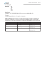
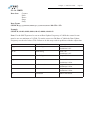
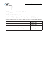
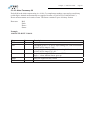
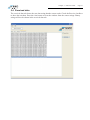
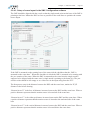
1
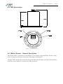
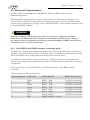
SMC IMU
Motion Sensors
IMU MANUAL
All rights to the IMU-106, IMU-107 and IMU-108
and SMC system are reserved
Copyright © by Ship Motion Control Sweden AB
All rights reserved.
SMC IMU Manual Rev 20
Note: The guidelines for installation presented here must be regarded as a basis for detailed plans
prepared by the installation shipyard or company.
Copyright © 2009
The contents of this manual are the copyright of the publisher and may
not be reproduced (even extracts) unless permission is granted. Every care
has been taken to ensure the accuracy of the information contained in this
manual, but no liability can be accepted for any errors or omission. The
right to make design modifications is reserved.
Contact information
Company : Ship Motion Control Sweden AB
Email:
[email protected]
[email protected]
Phone:
+46 8 644 5010
Address:
Stubbsundsvägen 13
131 41 Nacka
Sweden
Table of Contents
1
2
INTRODUCTION
5
SYSTEM DESCRIPTION
6
2.1
2.2
2.3
3
4
STORAGE
4.4
4.5
4.6
4.7
5.3
5.4
5.5
5.6
IMU Configuration Software
5.1.1 Default settings at factory
5.1.2 Settings
Protocol
5.3.1 SMC standard protocols
5.3.2 Additional Protocols
Received data
Serial Input
5.5.1 Junction Box connections for external input
5.5.2 Aiding via GPS and Speed Log
5.5.3 Heading Input
5.5.4 AHC (Active Heave Compensation)
Remote Heave
MOTION SENSOR OPERATION
6.1
6.2
7
Location
Deck Mounted (mounted on horizontal surface)
Sideways mounting (mounted on a vertical surface)
4.3.1 Top of the IMU pointing to the Bow
4.3.2 Top of the IMU pointing to the Starboard
4.3.3 Top of the IMU pointing to the Stern
4.3.4 Top of the IMU pointing to the Port
IMU dimensions
Motion Sensor – General Description
Electrical Communication
4.6.1 Serial RS232 and RS422 interface connection guide
4.6.2 RS422 cable connection
4.6.3 RS232 cable connection
Electrical Installation
4.7.1 Starting the motion sensor, quick guide
IMU CONFIGURATION SOFTWARE GUIDE
5.1
6
UNPACKING
AND
INSTALLATION
4.1
4.2
4.3
5
Optional PC based software
Principle of Operation
Spatial Movement (Coordinate System)
Settling Time
Heave Operation
SERVICE
7.1
7.2
AND
WARRANTY
Technical Support
Warranty
7.1.1 Limit of liability
6
7
8
9
10
10
11
13
13
13
14
14
15
15
16
16
17
17
17
18
19
19
20
20
22
22
29
33
34
35
36
36
37
41
42
42
42
43
43
44
44
8
TECHNICAL SPECIFICATIONS
45
9
FAQ
46
Chapter 1 - Introduction
Page 5
1 Introduction
This user’s manual gives basic information about your IMU-106, IMU-107 or IMU-108 motion
sensor, their basic function and how to use them. Instructions for shipping, storing, handling and
installing the equipment are also given.
The motion sensor must be installed according to the instructions in this manual.
Chapter 2 - System Description
Page 6
2 System Description
The SMC IMU motion sensors are designed around accelerometers and gyroscopes with 6 degrees
of freedom.
In its basic form the SMC motion sensor consists of one IMU linked to a PC or instrument to give
a visual real-time display and analysis of an objects motion.
2.1 Optional PC based software
There are several optional PC based motion monitoring software packages available from SMC.
These give the opportunity to graphically present all occurring vessel motions measured by
the motion sensor. The PC based systems can be customized to the customer specifications.
Meteorological instruments are commonly integrated to the SMC software together with the
motion sensor. The software displays the integrated instruments in real-time and is also logging the
data for future analysis
The software packages use mathematical calculations to produce trend analysis that can be used
to warn an operator of any abnormal motions. Two examples of SMC software packages are
SMCems (Environmental Monitoring System) and SMChms (Helideck Monitoring System).
SMCems is a general monitoring tool that makes it possible to log and display all ship motions.
SMChms is a tool custom made to monitor the motions of a helicopter take off and landing deck.
Chapter 2 - System Description
Page 7
2.2 Principle of Operation
The SMC motion sensors consists of separate axial measurement component groups converting
signals from actual movements via accelerometers and gyroscopes into output data of angles and
attitude. The output parameters are presented in a digital output string via RS422 (default) or
RS232.
Each separate axial group consists of gyroscopes, accelerometers and temperature sensors. All data
from the different sensor elements is processed and filtered in the motion sensor’s CPU.
The signal from the gyroscopes are combined with the signal from the accelerometers in a Kalman
filter to provide the output of acceleration values and angle values from the motion sensor with
limited influence of accelerations. Vibrations are filtered away in the Kalman filter used inside the
motion sensor.
Heave, surge and sway is calculated by integrating the acceleration in the X, Y and Z axis twice.
The zero point for heave, surge and sway will be the average of the output over a time of ~4
cycles. The calculations of the distances are optimized for continues motion.
In the calibration process which is individual for every motion sensor the g-values from the
accelerometers and angle rate are from the gyros are calibrated over the stated temperature range.
SMC are using a 3 axis calibration machine that is equipped with a temperature chamber.
Figure 2.1: System Structure
Gyro
Signal
Accelerometer
Signal
X-axis
Gyro
Signal
Accelerometer
Signal
Y-axis
Gyro
Signal
Accelerometer
Signal
Z-axis
Digital Signal
Processing
Filter
RS232
RS422
Chapter 2 - System Description
Page 8
2.3 Spatial Movement (Coordinate System)
The SMC motion sensor defines its body axis from the Tait-Bryan/Euler angles.
In the SMC motion sensors the coordinate system can be defined by a simple setting option in the
PC based SMC setup software that follows the motion sensor. The user can choose between the
rigid body coordinate system and the absolute earth coordinate system.
From the SMC setup software motion sensor offset in roll, pitch and yaw can be set for alignment
errors in the physical installations. It is also possible to invert the axis to fit the receiving
application. The SMC default rotational and acceleration directions are defined in the drawing
below. By setting an offset in the SMC setup software the motion sensor rotates its coordinate
system. For optimum performance align the motion sensor as good as possible before setting up
offsets electronically.
Pitch is the rotation around the transverse axis, the axis running form starboard to port of the
vessel. Roll is the rotation around the longitudinal axis, the axis running from the bow to the stern
of the vessel. Yaw is the rotation around vertical axis.
+
Z
Heave
Sway
Y
+
Roll +
-
X
+
Surge
Yaw +
Pitch +
Chapter 3 - Storage and Unpacking
Page 9
3 Storage and Unpacking
Unpack the equipment and remove all the packaging materials and shipping carton.
The equipment should be inspected for damage during shipment. If damage has occurred during
transit, all the shipping cartons and packaging materials should be stored for further investigation.
If the damage is visible a claim for shipping damage should be filed immediately.
Because of the sensitive nature of the IMU’s the package must not be dropped.
Chapter 4 - Installation
Page 10
4 Installation
The SMC motion sensor has to be installed according to the instructions of this manual. Please
save this operators manual for future reference.
4.1 Location
The optimal positioning of the sensor is normally as close to the vessels centre of gravity as
possible. The motion sensor is designed to be installed in an internal environment.
Recommendations of location of the motion sensor to obtain optimal performance:
Roll & Pitch; When mounting the IMU, take care to align the sensor according to the vessels
roll and pitch axis. If there is excessive axis misalignment roll motions will induce errors in pitch
measurements and vice versa. Small alignment errors can be adjusted mathematically inside the
motion sensor. The alignment offsets are set from the SMC setup software.
Heave/acceleration; If the sensor is equipped with Heave/acceleration measurement it is
recommended that the motion sensor is placed as close to the point where Heave/acceleration is to
be measured.
Temperature; The SMC motion sensors have been calibrated and designed to work within
the stated temperature range as specified in the motion sensor technical specifications. SMC
recommend that the motion sensor is mounted in a location without extreme variations in
temperature.
Vibrations; Avoid mounting the motion sensor on any hull location that is subject to substantial
vibrations. At the same time avoid mounting the sensors near to machines with sporadic operation
e.g. hydraulic pumps.
Water; The SMC IMU-106, IMU-107 and IMU-108 is IP66 protection rated. The standard surface
unit is designed to be mounted in an internal environment but is possible to mount outdoor. The
SMC IMU-106-30, IMU-107-30 and IMU-108-30 is IP68 water proof down to 30 meters depth.
Mounting orientation; The IMU is calibrated from the factory for Deck or Sideways orientation.
Deck orientation is when the IMU is mounted on a horizontal surface. Sideways orientation is
when the IMU is calibrated to be mounted on a vertical surface. The Deck mounting calibration
is the default orientation. A unit that has been calibrated for Deck mounting cannot be used in a
Sideways mounting and vice verse without recalibration of the IMU at the factory.
Chapter 4 - Installation
Page 11
4.2 Deck Mounted (mounted on horizontal surface)
When the IMU is calibrated for Deck mounting the unit cannot be used for Sideway mounting
without a recalibration at the factory.
The mounting of the motion sensor should be carried out with the mounting plate lying
horizontally. The notches are marking the rotation of the motion sensor. The indexes (see fig)
marking the P-axis (Pitch axis) is supposed to be mounted pointing to port/starboard. The single
notch is to be mounted pointing to the bow of the vessel.
Place the motion sensor flat on the mounting location that have been selected and align the P-axis
mounting indexes along the vessels centre of rotation or on the axis you have defined. (the single
notch should be pointing to the bow)
Figure 4.1: Axis Alignment
Chapter 4 - Installation
Page 12
The mounting plate has been specifically designed to enable ease of installation by allowing
freedom of movement to help align the motion sensor. The motion sensor is not shipped with
mounting screws or bolts. The mounting plate can be used with a maximum M8 screw or
bolt. Remove the motion sensor while the mounting location is prepared. See motion sensor
Dimensions Figure 4.3
After drilling any holes for mounting, be sure to de-burr the holes and clean the mounting
location of any debris that could induce errors.
Mount and screw the motion sensor in position, taking care to align the IMU as best possible.
In the SMC setup software there is a function to fine tune the motion sensor alignment in the
X, Y and Z axis electronically. This setting will rotate the coordinate system electronically
inside the motion sensor. See the section on Motion Sensor Setup Software for further
instructions.
Figure 4.2: Motion Sensor Mounting
Chapter 4 - Installation
Page 13
4.3 Sideways mounting (mounted on a vertical surface)
When the IMU is calibrated for Sideways mounting the unit cannot be used for Deck mounting
without a recalibration at the factory.
The mounting of the motion sensor should be carried out with the mounting plate lying vertically.
The notches marks the rotation of the motion sensor. The indexes marking the P-axis should be
mounted pointing to vertical. The single notch should be mounted pointing horizontally to the
bow/stern/port/starboard of the vessel. Depending of the mounting direction the unit needs to be
setup for its coordinate system. This is done in the SMC setup software.
The mounting plate has been specifically designed to enable ease of installation by allowing
freedom of movement to help align the motion sensor. The motion sensor is not shipped with
mounting screws or bolts. The mounting plate can be used with a maximum M8 screw or
bolt. Remove the motion sensor while the mounting location is prepared. See motion sensor
Dimensions Figure 4.3
After drilling any holes for mounting, be sure to de-burr the holes and clean the mounting location
of any debris that could induce errors.
Mount and screw the motion sensor in position, taking care to align the IMU as best possible.
If the motion sensor has been mounted upside down, with the single notch pointing in the wrong
direction, the output signal from the motion sensor will display – 180 degrees wrong angle for roll
output. If the unit has been mounted incorrectly the mounting will need to be corrected. If the IMU
is mounted incorrectly it will not work within its calibrated range and output incorrect values.
In the SMC setup software there is a function to fine tune the motion sensor alignment in the X,
Y and Z axis electronically. This setting will rotate the coordinate system electronically inside the
motion sensor. See the section on Motion Sensor Setup Software for further instructions.
If an incorrect mounting selection is done in the setup software the coordinate system will be
inverted.
When mounting the motion sensor sideways the user is given 4 mounting options in the SMC
setup software to rotate its coordinate system correct.
4.3.1 Top of the IMU pointing to the Bow
When the IMU top (where the connector is located) is pointing to the Bow of the vessel the single
notch should be pointing horizontally against the Starboard.
In the SMC setup software “Top of the IMU pointing to the Bow” must be selected.
4.3.2 Top of the IMU pointing to the Starboard
When the IMU top (where the connector is located) is pointing to the Starboard of the vessel the
single notch should be pointing horizontally against the Stern.
In the SMC setup software “Top of the IMU pointing to the Starboard” must be selected.
Chapter 4 - Installation
Page 14
4.3.3 Top of the IMU pointing to the Stern
When the IMU top (where the connector is located) is pointing to the Stern of the vessel the single
notch should be pointing horizontally against the Port.
In the SMC setup software “Top of the IMU pointing to the Stern” must be selected.
4.3.4 Top of the IMU pointing to the Port
When the IMU top (where the connector is located) is pointing to the Port of the vessel the single
notch should be pointing horizontally against the Bow.
In the SMC setup software “Top of the IMU pointing to the Port” must be selected.
Chapter 4 - Installation
Page 15
4.4 IMU dimensions
Figure 4.3: SMC IMU dimensions
4.5 Motion Sensor – General Description
The motion sensor’s electronics are shielded in a cast of plastic supported inside an outer casing
made of stainless steel to prevent damage from impact and moisture.
The SMC IMU should not be opened as this could affect the warranty on the unit. All operations
inside the sensor should be carried out by SMC personnel.
Chapter 4 - Installation
Page 16
4.6 Electrical Communication
The SMC IMU are preconfigured as either RS422 (default) or RS232 that is set in the
manufacturing process.
RS422 (default) communication can achieve data transfer over cable distances of up to 1 300
meters. RS232 is designed for short distance communication, (max 5 meters). The SMC motion
sensors require a separate power supply system. The RS422/RS232 cable normally terminates with
a conventional DB9 connector.
WARNING
Permanent damage to the motion sensor may occur if power is applied to the digital
connections. It is important to check the power connections by measuring the voltage at
the connector prior to the motion sensor being connected. Damage resulting from incorrect
connection is not covered by the warranty.
4.6.1 Serial RS232 and RS422 interface connection guide
The IMU’s are equipped with both RS422 and RS232 interface. In the below table information is
available of the cable communications. The motion sensor is at all times communicating over both
RS232 and RS422 and no configuration is needed inside the motion sensor.
As default one cable interface into the junction box. “(if RS232 connected)” means that if the
motion sensor is supposed to communicate over RS232 the DB9 connector should have the below
configuration.
If the junction box is wired for RS422 the “(if RS422 connected)” in the DB9 column is
connected.
Cable connection to IMU motion sensor
Sensor Connector Cable color
1
2
3
4
5
6
11
12
White
Red
Brown
Orange
Green
Purple
Grey
Pink
Sensor function
DB9 to PC/converter
RS232 – RxD
RS232 – TxD
RS422 – TxD+
RS422 – TxDRS422 – RxDRS422 – RxD+
Supply Voltage Supply Voltage 12-30VDC
3 (if RS232 connected)
2 (if RS232 connected)
3 (if RS422 connected)
4 (if RS422 connected)
1 (if RS422 connected)
2 (if RS422 connected)
5 (if RS232 connected)
Chapter 4 - Installation
Page 17
4.6.2 RS422 cable connection
The RS422 cable consists of two twisted-pairs conductors (4 wires) for bi-directional
communication.
The thickness of power cables is such that there is no more than a 2V drop with a 50 mA current
applied over an exceptional length of cable. Cable and conductors are supplied on demand for an
additional cost. The maximum cable length allowed is approximately 1 300 m using RS422.
4.6.3 RS232 cable connection
The RS232 cable consists of a single twisted-pair conductors (2 wires) for bi-directional
communication, plus 2 power supply wires. Total 4 conductors.
The maximum cable length allowed is approximately 5 m using RS232.
4.7 Electrical Installation
The SMC IMU’s are powered with a standard 12 vdc or 24 vdc supply. It is possible however to
supply power at any voltage between 9 vdc and 30 vdc.
The SMC IMU’s does not have an on/off switch. The motion sensor operates as soon as power is
supplied to it. There is an initialization of the IMU that prevent it from outputting numerical data
for the first 4 minutes after the motion sensor has been powered up.
Chapter 4 - Installation
Page 18
4.7.1 Starting the motion sensor, quick guide
Connect the motion sensor to the PC/device. Note that the motion sensor can be either factory set
to RS422 or RS232.
Start the SMC IMU Configuration software which is supplied with the motion sensor.
Click on the ‘Set PC COM port’ button to set the comport settings or press the Search IMU button
to let the IMU Configuration software to locate the proper comport settings.
Select the com port that the motion sensor has been connected to and then select the factory set
default baud rate 115200 if this has not been changed by a user and press OK.
The Motion Sensor values appear in the Sensor values display when the settling time has
elapsed (4 minutes) and the correct PC com setting has been set to match the motion sensor
communication settings.
Chapter 5 - Software Guide
Page 19
5 IMU Configuration Software Guide
5.1 IMU Configuration Software
After the motion sensor has been mounted correctly the SMC IMU Configuration software can
be used to set up the Motion sensor configuration and communication parameters after the user
requirements.
The settings made from the IMU Configuration software is made inside the motion sensor. The
settings are stored in a flash memory inside the motion sensor and is not dependant of power
supply or battery power.
SMC IMU Configuration software v3.3.1.7
Chapter 5 - Software Guide
Page 20
5.1.1 Default settings at factory
There are several Motion Sensor parameters that can be selected from the Configuration software.
The factory default settings are as follows.
If you want to change the default settings it is recommended to do it after the installation but
before you connect to any systems. Please refer to 5.1.2 (setup).
Settings
Data Update Frequency
Bit Rate
Data Bits
Stop Bits
Parity
Flow Control
Angular Filter
Coordinate system
Selection
1 - 100Hz
9600
19200
38400
57600
115200
8
1
None
Odd
Even
None
Filter 1 0-1000
Filter 2 0-1000
Earth
Motion sensor
Factory Default
100
115200
8
1
None
None
Filter 1 100
Filter 2 0.01
Earth
5.1.2 Settings
Set COM-port configuration; The COM-port settings are where and with which parameters the
computer is receiving data from the sensor. These should be the same as in the sending sensor. The
sensor will always send its data with 8 data bits, 1 stop bit, and no parity and without flow control.
IMU Information; Shows information about motion sensor IMU type, mounting orientation,
serial number, IMU firmware, date and time. If a signal string selected does not include time the
motion sensor time will not be shown in the setup software.
IMU Output Values; Shows data sent by the motion sensor in real time. OOnly values that are
being output from the IMU are displayed in this section.
IMU Zero Position; By pressing the “Set Zero Position” button the current IMU inclination will
be set to be the zero point, i.e. reference point for the angle measurements. “Clear zero” button
will enter 0 offset for the roll, pitch and yaw values.
Mounting Offset Angles; The offsets can be manually entered into the motion sensor instead of
using the IMU Zero Position. The yaw alignment has to set manually. The offsets entered into the
IMU rotates its coordinate system. To achieve accurate angles outputs from the motion sensor the
yaw axis alignment is very crucial. Try to mount the motion sensor as good as possible physically
before adjusting the offsets electronically.
Chapter 5 - Software Guide
Page 21
Axis Inversion; Enables the sign inversion of the output signals from the motion sensor. See
Chapter 2 for information about SMC rotational definitions.
Mounting Orientation; Is available only if the IMU has been calibrated for sideways mounting
orientation. See Chapter 4 for more information about the mounting orientation options.
IMU Output Coordinate System; The IMU can be set to output its data in the earth coordinate
system or in the IMU coordinate system.
Surge, Sway and Heave can be set to be output in the earth coordinate system regardless of the
IMU coordinate setting has been selected for the angles.
Output Rate; Adjusts the number of times the IMU outputs its string per second. Choose the
wanted value in the list box and press the set button to set the wanted frequency.
Kalman Filter Settings
Filter 1 sets the filter for the accelerometers (default 100)
Filter 2 sets the filter for the gyros (default 0.01)
The value entered in the angle filter setting specifies how much each sensor type (accelerometer
and gyro) is “applied”. The lower value the more we apply the sensor type.
This means that the higher value that is set on the accelerometer the less influence the acceleration
will have. But it will also generate a bigger random walk from the gyros.
It is not advisable to change the settings for the Kalman Filter without consulting with SMC
The default button will reset the filter settings to the factory defaults.
IMU Bitrate and Parity; Adjusts the bit rate that the sensor uses for transmitting data. Write
down the selected Bitrate and Parity. To be able to connect to the IMU a matching communication
setting must be set for the receiving device
Available Bit rates: 9600, 19200, 38400, 57600, 115200
Note: For Long protocols such as SMCT / SMCA & SMCF the Bit Rate will have to be set to high
bit rates like 115200 if the Data Update Frequency is 100Hz to be able to transfer the data from the
motion sensor. See notes beside each protocol.
Read IMU Settings; By pressing the “Read Setting” button the setup software checks the current
IMU settings and displays them in the setup software.
Chapter 5 - Software Guide
Page 22
5.3 Protocol
Choose Protocol
The SMCsetup software enables the selection of a number of standard protocols by selecting a
protocol from the drop down menu and clicking on the set button.
Additional protocols can be set up by SMC to request.
5.3.1 SMC standard protocols
SMC Standard - This is a NMEA 0183 based compatible string.
Chapter 5 - Software Guide
Page 23
5.3.1.1 SMCS
Data Sent
Roll
Pitch
Heave
Data Frame
$PSMCS,±yy.yyy,±xx.xxx,±hh.hh<CR><LF>
Example
$PSMCS,+00.089,-00.888,-00.04
Note: For the SMCS protocol to run at an Data Update Frequency of 100Hz the sensor bit rate
must be set at a minimum of 38400. To run the sensor at a Bit Rate of 19200 the Data Update
Frequency needs to be below 53Hz. Failure to do this may result in problems with the output data.
yy.yyy
Roll in deg
xx.xxx
Pitch in deg
hh.hh
Heave in m
Roll ±30º
Resolution 0.001º
Pitch ±30º
Resolution 0.001º
Heave ±10m
Resolution 0.01m
Chapter 5 - Software Guide
Page 24
5.3.1.2 SMCT
Data Sent
Date
Time
Roll
Pitch
Heave
Data Frame
$PSMCT,YYYY/MM/DD,HH:MS:SS.HU±yy.yy,±xx.xx,±hh.hh<CR><LF>
Example
$PSMCT,2006/11/07,15:54:23.71,-06.22,+21.60,-00.20
Note: For the SMCT protocol to run at an Data Update Frequency of 100Hz the sensor bit rate
must be set at a minimum of 57600. To run the sensor at a Bit Rate of 38400 the Data Update
Frequency needs to be below 67Hz. Failure to do this may result in problems with the output data.
YYYY/MM/DD
HH:MI:SS.HU
yy.yy
xx.xx
hh.hh
Year/month/day
Hour:minute:second.hundredth
Roll in deg
Roll ±30º
Resolution 0.01º
Pitch in deg
Pitch ±30º
Resolution 0.01º
Heave in m
Heave ±10m
Resolution 0.01m
Chapter 5 - Software Guide
Page 25
5.3.1.3 SMCF
Data Sent
Serial Number
Roll
Pitch
Heave
Surge
Sway
Data Frame
$PSMCFnnnnnn,±yy.yyy,±xx.xxx,±hh.hh,±ss.ss,±ww.ww<CR><LF>
Example
$PSMCF1082149,+00.129,-00.753,-00.02,-00.56,-00.42
Note: For the SMCF protocol to run at an Data Update Frequency of 100Hz the sensor bit rate
must be set at a minimum of 57600. To run the sensor at a Bit Rate of 38400 the Data Update
Frequency needs to be below 67Hz. Failure to do this may result in problems with the output data.
nnnnnn
yy.yyy
Unit Serial number
Roll in deg
xx.xxx
Pitch in deg
hh.hh
Heave in m
ss.ss
Surge in m
ww.ww
Sway in m
Roll ±30º
Resolution 0.001º
Pitch ±30º
Resolution 0.001º
Heave ±10m
Resolution 0.01m
Surge ±10m
Resolution 0.01m
Sway ±10m
Resolution 0.01m
Chapter 5 - Software Guide
Page 26
5.3.1.4 SMCC
Data Sent
Roll (yy)
Pitch (xx)
Yaw (zz)
Surge (ss)
Sway (ww)
Heave (hh)
Surge velocity (sv)
Sway velocity (wv)
Heave velocity (hv)
Acceleration X (ax)
Acceleration Y (ay)
Acceleration Z (az)
Data Frame
$PSMCC,±yy.yy,±xx.xx,±zz.zz,±ss.ss,±ww.ww,±hh.hh,±sv.sv,±wv.wv,±hv.hv,±ax.axa,
±ay.aya,±az.aza*hh<CR><LF>
Example
$PSMCC,-09.42,-02.85,-144.16,+00.28,-00.05,+00.00,+00.01,-00.00,+00.00,+00.004,-00.000,00.005*71
Note: For the SMCC protocol to run at an Data Update Frequency of 100Hz the sensor bit rate
must be set at a minimum of 115200. To run the sensor at a Bit Rate of 38400 the Data Update
Frequency needs to be below 30 Hz. Failure to do this may result in problems with the output data.
yy.yy
Roll in deg
Roll ±30º
Resolution 0.01º
xx.xx
Pitch in deg
Pitch ±30º
Resolution 0.01º
zz.zz
Yaw in deg
Yaw 0 - 360º
Resolution 0.01º
ss.ss
Surge in m
Surge ±10m
Resolution 0.01m
ww.ww
Sway in m
Sway ±10m
Resolution 0.01m
hh.hh
Heave in m
Heave ±10m
Resolution 0.01m
sv.sv
Surge velocity in m/s
Surge velocity ±10 m/s
Resolution 0.01 m/s
wv.wv
Sway velocity in m/s
Sway velocity ±10 m/s
Resolution 0.01 m/s
hv.hv
Heave velocity in m/s
Heave velocity ±10 m/s
Resolution 0.01 m/s
X acceleration ±10 m/s2
ax.axa
X acceleration in m/s2
Resolution 0.001 m/s2
ay.aya
Y acceleration in m/s2
Y acceleration ±10 m/s2
Resolution 0.001 m/s2
az.aza
Z acceleration in m/s2
Z acceleration ±10 m/s2
Resolution 0.001 m/s2
Chapter 5 - Software Guide
Page 27
5.3.1.4 SMCD
Data Sent
Counter
Pitch
Heave
Surge
Sway
Data Frame
$PSMCD,±yy.yy,±xx.xx,±zzz.z,±yv.yv,±xv.xv,±zv.zv*hh<CR><LF>
Example
$PSMCD,+00.09,-00.89,+000.0,-00.03,+00.00,+00.00*42
Note: For the SMCD protocol to run at an Data Update Frequency of 100Hz the sensor bit rate
must be set at a minimum of 115200. To run the sensor at a Bit Rate of 38400 the Data Update
Frequency needs to be below 67Hz. Failure to do this may result in problems with the output data.
nnnnnn
yy.yy
Unit Serial number
Roll in deg
xx.xx
Pitch in deg
zzz.z
Yaw in deg
yv.yv
Roll rate m/s
xv.xv
Pitch rate m/s
zv.zv
Yaw rate m/s
hh
Checksum
Roll ±30º
Resolution 0.01º
Pitch ±30º
Resolution 0.01º
Output 000.0
Heave ±10m
Resolution 0.01m
Surge ±10m
Resolution 0.01m
Sway ±10m
Resolution 0.01m
NMEA checksum
Chapter 5 - Software Guide
Page 28
5.3.1.5 SMCH
Data Sent
Roll
Pitch
Heave
Heave rate
Data Frame
$PSMCH,±yy.yyy,±xx.xxx,±hh.hh,±hv.hv<CR><LF>
Example
$PSMCH,+00.097,-00.895,-00.04,-00.00
Note: For the SMCH protocol to run at an Data Update Frequency of 100Hz the sensor bit rate
must be set at a minimum of 57600. To run the sensor at a Bit Rate of 38400 the Data Update
Frequency needs to be below 90Hz. Failure to do this may result in problems with the output data.
yy.yyy
Roll in deg
xx.xxx
Pitch in deg
hh.hh
Heave in m
hv.hv
Heave velocity m/s
Roll ±30º
Resolution 0.001º
Pitch ±30º
Resolution 0.001º
Heave ±10m
Resolution 0.01m
Heave Velocity ±99m/s
Resolution 0.01m/s
Chapter 5 - Software Guide
Page 29
5.3.2 Additional Protocols
The SMC S-108 sensor can be pre-programmed with additional customer requested signal strings.
These will be displayed below.
5.3.2.1 TSS1/DMS
TSS proprietary protocol with Heave
Data Sent
Horizontal Acceleration
Vertical Accelertation
Roll
Pitch
Heave
Data Frame
:XXAAAASMHHHHQMRRRRSMPPPP<CR><LF>
Example
:12D5FF -0002U 0007 -008
Note: For the TSS1 protocol to run at an Data Update Frequency of 100Hz the sensor bit rate must
be set at a minimum of 38400. To run the sensor at a Bit Rate of 19200 the Data Update Frequency
needs to be below 58Hz. Failure to do this may result in problems with the output data.
:
XX
AAAA
S
MHHHH
LSB start character
Horizontal Acc
Vertical Acc
Space Character
Heave
Q
Status flag
MRRRR
Roll in deg
MPPPP
Pitch in deg
Hexadecimal value
Hexadecimal value
Heave: ±10 m
Unit 1cm
M = space if positive
– if negative
‘U’ Settled mode (Nominal)
’u’ settling mode
Roll ± 45º
Unit 0.01º
M = space if positive
– if negative
Pitch ± 45º
Unit 0.01º
M = space if positive
– if negative
Chapter 5 - Software Guide
Page 30
5.3.2.2 Atlas Fansweep 20
Each field in the Atlas output string is a 16-bit 2’s complement number expressed as two binary
coded digits. Attitude measurements are supplied in units of (360º/65536=0.0054931641º).
Heave measurements are in units of mm. The frame contains 9 bytes in binary format.
Data sent
Roll
Pitch
Heave
Status
Example
10 02 B5 FE 0B FF 21 06 10
Data
DLE
Roll
Bytes
1
2
Pitch
2
Heave
2
Status
DLE
1
1
Description
0x10
Unsiqned 16 bit, i.e. 0..65535 representing 360° with a resolution
of 360°/65536 range 0..360°
Unsiqned 16 bit, i.e. 0..65535 representing 360° with a resolution
of 360°/65536 range 270°..90°
Siqned 16 bit range -32767 mm to + 32767 mm
Sign ‘+’ when Motion Sensor goes up
0x06 for alignment fully settled
0x10
Chapter 5 - Software Guide
Page 31
5.3.2.3 EM3000
The EM3000 format consists of a fixed length message using single byte unsigned, 2-byte
unsigned and 2-byte two complement integer data elements. For the 2-byte elements, the least
significant byte is transmitted first.
Data sent
Element
Status byte
Header
Roll
Pitch
Heave
Heading
Roll
Pitch
Heave
Heading (SMC output 0)
Scaling
0.01 degrees
0.01 degrees
1 cm
0.01 degrees
Format
Unsigned
Unsigned
Integer
Integer
Integer
Unsigned
Bytes
1
1
2
2
2
2
Value
90 Hex
-17999 to 17999
-17999 to 17999
-999 to 999
SMC output 0
Roll is positive with port side up. Pitch is positive with bow up. Heave is positive up.
The status byte information:
Value
90 Hex
91 Hex
Interpretation
Normal mode
Unsettled mode
Chapter 5 - Software Guide
Page 32
5.3.2.4 Binary protocols
Descriptions of the binary protocol SMC1 are available on demand.
SMC2
The Ship Data is received at a message frequency of 100Hz +/- 1Hz, and at a timing interval (first
byte of successive messages) of 10mS +/-1mS. This ensures a regular and consistent data input to
the system.
The serial messages are sent at 38400 bps, 8 data bits, 1 start bit, 1 stop bit, even Parity. (total
11bits per character). The interface will be receive-only. No software or hardware handshaking
will be employed. Messages will be checked on receipt for parity and credible data content.
Message Segment Byte Description
Header (32 Bits)
SOH
Message Length
Message Type
EOH
Data
Pitch Byte 1
Pitch Byte 2
Pitch Byte 3
Pitch Byte 4
Roll Byte 1
Roll Byte 2
Roll Byte 3
Roll Byte 4
Hex
0x01
0x0D
0x00
0x1E
LSB
Remark
Start of Header Byte
Remaining No. of Bytes to Follow
Message Code
End of Header
32 Bits representing Ship’s (absolute) Pitch as
a signed integer
MSB
+ive Pitch = Bow up;
-ive Pitch = Bow down.
See section 3.2.2.1 for full definition of Ship’s
Pitch.
See Note 1 for precision.
32 Bits representing Ship’s (absolute) Roll as a
signed integer.
LSB
MSB
+ive Roll = Port up;
-ive Roll = Port down.
See section 3.2.2.1, for full definition of Ship’s
Roll.
See Note 1 for precision.
Invalidity byte flag:
0x00 = Valid;
0x01-0xFF = Invalid;
0x04
End of Message
Pitch Invalid
Roll Invalid
Footer
EOM
NOTES
Note 1 : Pitch/Roll Value = 360/(232).
0 (0000000000 Hex) = 0 degrees
1 (0000000001 Hex) = +0.00000008382 Degrees
-1 (0FFFFFFFF Hex)= -0.00000008382 Degrees
Chapter 5 - Software Guide
Page 33
5.4 Received data
The received data tab shows the raw data string that the sensor sends. Check the Receive checkbox
to show the sent data. Press the clear button to clear the window from the sensor strings. Binary
strings will not be shown in the received data tab.
Chapter 5 - Software Guide
Page 34
5.5 Serial Input
The SMC IMU has two RS232 serial ports for input from external devices.
These ports can be used for
Aiding in vessel turns; input from GPS, Speed log
Heading aiding; GyroCompass or GPS
Remote heave for AHC (Active Heave Compensation) in crane applications; Encoders via
PLC
Chapter 5 - Software Guide
Page 35
5.5.1 Junction Box connections for external input
The default bitrate for the external input is 4800 bps but can be changed from the configuration
software.
Inside the SMC Junction Box the connection from the external device should be as follows.
External device RxD to Terminal 7
External device TxD to Terminal 8
Ground to Terminal or
External device RxD to Terminal 9
External device TxD to Terminal 10
Ground to Terminal Connections on a DB9 connector to Junction Box
DB9 Pin 3 to JB Terminal 7
DB9 Pin 2 to JB Terminal 8
DB9 Pin 5 to JB Terminal or
DB9 Pin 3 to JB Terminal 9
DB9 Pin 2 to JB Terminal 10
DB9 Pin 5 to JB Terminal -
Chapter 5 - Software Guide
Page 36
5.5.2 Aiding via GPS and Speed Log
During vessel turns with small vessels a centrifugal force is generated from the turn. This force
has a negative effect on the angle and heave calculation. By knowing the vessel velocity the
centrifugal force can be estimated inside the IMU and the centrifugal effect can be heavily
reduced, improving the accuracy of the readings from the IMU.
The SMC IMU accepts velocity input from a GPS or a speed log.
The accepted input strings for the velocity input are
$xxRMC
$xxRMA
$xxVTG
$xxVBV
$xxVHW
To confirm that the IMU is receiving data from the velocity device use the SMC configuration
software. Select the “Verify Velocity Input” in the serial input tab in the configuration software.
The IMU replies with information about the time since the last reading and the velocity received.
5.5.3 Heading Input
When a gyrocompass is connected (or a GPS is selected to be used for heading input), the IMU
will use the gyrocompass for aiding of the yaw signal, combining the data from internal gyros in
the IMU with the input from the external gyrocompass. The output is available in strings where
yaw or heading is available. See the IMU user manual for a list of available data strings.
The accepted strings from the GyroCompass are $xxHDT and $xxHDG.
Heading can also be retrieved from the GPS string but is not advisable if the vessel is not under
constant motion. The $GPHDG string is not accepted as default for the heading input. To use the
GPS heading data for yaw aiding tick the “Use GPS heading input for yaw aiding if available”
checkbox in the external input tab in the SMC configuration software otherwise the $GPHDG
string will be ignored.
To confirm that the IMU is receiving data from the heading device use the SMC configuration
software click the verify input in the serial input tab in the configuration software. The IMU replies
with information about the time since last reading and the heading received.
Chapter 5 - Software Guide
Page 37
5.5.4 AHC (Active Heave Compensation)
Note that SMC will not be responsible for damages that occur related to Active Heave
Compensation. A “failsafe” handling system must be built into the system so that if there is a
failure in the IMU/PLC or the encoder feeding the active heave operation must be cancelled
automatically.
SMC has developed a remote heave function that accepts dynamic crane position data for active
heave compensation in marine crane applications. With the remote heave for Crane Operations
active the IMU will continually calculate the remote heave data based on the information that is
supplied to the IMU from the crane encoders. The position for the remote heave is continuously
calculated from the crane encoder data. Remote heave and remote heave velocity data is then
calculated for any requested single point location along the crane boom which can be used to
compensate for the vessel motions during crane operations.
Remote heave
and heave velocity
is calculated to this postion
Crane
Encoders
Winch control
PLC
Encoders
Remote heave
IMU
Manual
Control
By activating the “Remote heave for Crane Operations” by checking the checkbox in the remote
heave tab in the IMU configuration software, the crane settings will be enabled.
How to setup remote heave for active heave compensation with encoder feedback to the IMU.
Chapter 5 - Software Guide
Page 38
5.5.4.1 String Input
The accepted input from the Encoder/PLC with the angular data is as follows in ASCII code
$PENCO,encoder1,encoder2,encoder3,encoder4,encoder5
Where
encoder1 is the encoder for the yaw rotation marked as 1 angle in the below drawing
encoder2 is the encoder for the first knuckle marked as 2 angle in the below drawing
encoder3 is the encoder for the second knuckle marked as 3 angle in the below drawing
encoder4 is the encoder for the third knuckle marked as 4 angle in the below drawing
encoder5 is the encoder for the forth knuckle
The IMU accepts radians or degrees in the $PENCO string which is selectable from the
configuration software under “Angle Unit” drop down box.
If one rotational point is not being used or is not available input 0 or leave the position blank in the
PLC string.
For example (yaw rotation is not available)
$PENCO,0,encoder2,encoder3,encoder4,encoder5
or
$PENCO,,encoder2,encoder3,encoder4,encoder5
5.5.4.2 Telescopic arm input data
If the crane has a telescopic arm, data can be entered at the next position from the previous
encoder angle and the distance data entered into the configuration software. In the example below
this telescopic arm would have been entered into position 4 in the configuration software and the
checkbox for the telescopic information should be ticked for the specific row. The string with
encoder values will then need the distance information in meters instead of the angle value for
the rotation encoder. The example below displays a crane with a yaw rotation, and two rotational
encoders followed by a telescopic arm.
For example
$PENCO,encoder1,encoder2,encoder3,distance4
Chapter 5 - Software Guide
Page 39
5.5.4.3 Setup of crane layout in the SMC Configuration software
The IMU should be aligned with the vessel so that the single notch point on the base of the IMU is
pointing to the bow. Mount the IMU as close as possible to the crane base to optimize the remote
heave output.
If the IMU is mounted on the rotating base of the crane tick the checkbox that the “IMU is
mounted on the crane base”. When this checkbox is ticked the IMU is assumed to be rotating with
the yaw rotation of the crane. When the IMU is mounted on the crane base the single notch is
supposed to be aligned with the crane arm (ie single notch is pointing to the boom tip). The yaw
encoder value should be left empty or as a value zero in the input string from the PLC.
The first part to setup is the distance between the IMU and the crane base, marked as X,Y,Z
distance in the below drawing.
“Remote heave X” is the fore aft distance in meters between the IMU and the crane base. Where a
positive distance represents that the motion sensor is located aft of the crane base
“Remote heave Y” is the sideways distance in meters between the IMU and the crane base. Where
a positive distance represents that the motion sensor is located to the starboard side of the crane
base
“Remote heave Z” is the vertical distance in meters between the IMU and the crane base. Where a
positive distance represents that the motion sensor is located below the crane base.
Chapter 5 - Software Guide
Page 40
Secondly enter the offset for the each encoder. The offsets are defined as the vessels for aft line
and the vessel z direction.
For the encoder1 (yaw encoder) the offset has its reference position aligned with the vessel for aft
line. Encoder1 angles are seen from above. This means that when the crane is pointing to the fore
of the vessel the encoder should display 0 degrees, when the crane is pointing starboard side the
encoder should display 90 degrees angle. When the crane is pointing to the port side the encoder
value should be 270 degrees (if the default clockwise rotation is being used). The offset settings
can be done both in the PLC and by entering the offset value in the SMC configuration software.
For the encoders 2, 3 and 4 the angle is referring to the previous leg of the crane. Which means
that when there is no difference in the angle between leg 2 and 3 the incoder3 has 0 angle. The
encoder angles are illustrated as 2a, 3a and 4a in the below drawing.
Encoder 2, 3 and 4 rotations are seen from the starboard side looking at the port side of the crane.
The clockwise rotation is as default a positive rotation when seeing the crane from this position.
Counter clockwise can be selected by ticking the checkbox for the encoder. The rotational
directions displayed in the drawing below.
When a telescopic arm is being used the telescopic check button should be ticked and the offset is
then referring to the offset in the distance measured instead of the angle offset. Zero is when the
telescopic arm is fully pushed together. The distance column is disabled when the telescopic arm is
ticked as the distance to the start of the telescopic arm is to be entered in the previous row distance
info.
The second step is to setup the distance after the encoder to the next position. These are marked
as 1 distance, 2 distance, 3 distance, 4 distance in the below drawing. The distance is the length
between the rotational point to the next rotation point or location. The distance is entered in
meters.
By clicking the verify input the configuration software will then generate a sketch of the of the
current crane position, based on the data that has been entered into the system.
Chapter 5 - Software Guide
5.6
Page 41
Remote Heave
The remote heave function calculated the heave and the heave velocity output of the IMU to a
remote location from the IMU physical location. The setup of the remote heave is done in the
remote heave tab in the SMC configuration software.
“Remote heave X” is the fore aft distance in meters between the IMU and the crane base. Where a
positive distance represents that the motion sensor is located aft of the desired measurement point.
“Remote heave Y” is the sideways distance in meters between the IMU and the crane base. Where
a positive distance represents that the motion sensor is located to the starboard side of desired
measurement point.
“Remote heave Z” is the vertical distance in meters between the IMU and the crane base. Where a
positive distance represents that the motion sensor is located below the desired measurement point.
As the remote heave calculation is a combination of distance, angles and heave, a fixed angle
will give a constant heave position that is different from zero. As the heave definition is a relative
motion and the angle is an absolute angle SMC has added a filter to remove a fixed trim of the
vessel from the remote heave output. This is selectable from the checkbox “Filter remote heave for
relative zero position”.
Note that remote heave will not be as accurate as heave at the physical location of the IMU as the
remote heave is a combined calculation of heave and angle from a remote location. If the remote
heave distance is far from the physical location of the IMU the error from any small angular error
in the motion sensor, flexing hulls etc may generate a significant error in the remote heave output.
+
Z
Y
-
X
+
+
Chapter 6 - Motion Sensor Operation
Page 42
6 Motion Sensor Operation
6.1 Settling Time
The SMC IMU’s internal filtering system uses both past and present data to calculate the output.
Hence, immediately after being connected to its power source, the sensor will produce less
accurate measurements since there are only short sequences of historical data available for
processing. The SMC IMU has a settling time of approximately 4 minutes. This means that from
the motion sensor start up it will take 4 minutes till output data is shown. During this settling time
the sensor output dependant on protocol selected could read for example “$PSMCS,+rr.rr,+pp.
pp,+hh.hh”.
6.2 Heave Operation
SMC IMU-106 and IMU-108 uses a heave measurement and filter system that continually
monitors the motions and reviews the previous motions to maintain accurate results whatever the
vessel size and sea state. Heave is not available on the IMU-107 motion sensor.
Heave Zero Point; The zero point is set by the spectral analysis of the sinusoidal waveform
along with using filtering techniques that can track the zero point of the heave motions within a
maximum of 5 cycles. There is no need to input data of vessel type and sea states expected.
Heave Period; The SMC IMU technology enables the measurement of a heave cycles with
different periods without any manual setup. The IMU-106 and IMU-108 unit is adjusting its
calculations after the current motion and sea state and heave period.
Chapter 7 - Service and Warranty Page 43
7 Service and Warranty
7.1 Technical Support
If you experience any problem, or you have a question regarding your sensor please contact our
local agents or Ship Motion Control directly.
Refer to website www.shipmotion.se/contact.html
Please have the following information available
•
Equipment Model Number
•
Equipment Serial Number
•
Fault Description
Worldwide Service contact
Telephone:
+46 8 644 50 10 (CET 8am – 5pm)
e-mail:
[email protected]
Return Procedure
If this is not possible to solve the problem a Ship Motion Control technician will issue a Return
Material Authorization Number (RMA#). Please be ready to provide the following information.
•
Name
•
Address
•
Telephone, Fax, E-mail
•
Equipment Model Number
•
Equipment Serial Number
•
Installation Date
If the Sensor is under warranty, repairs are free. If not there is a repair charge. Please see Ship
Motion Controls warranty statement.
Pack the sensor in its original packaging, or suitable heavy packaging.
Mark the RMA# on the outside of the package
Return the Sensor, prepaid carrier to the address below.
Ship Motion Control Sweden AB
Stubbsundsvägen 13
131 41 Nacka
Sweden
Chapter 7 - Service and Warranty Page 44
7.2 Warranty
All products are inspected prior to shipment and guaranteed against defective material or
workmanship for a period of two (2) calendar years after date of purchase. Liabilities are limited
to repair, replacement, or refund of the factory quoted price (SMC AB’s option). SMC AB must be
notified and provided with sufficient time to remedy any product deficiencies that require factory
attention. This time period may include but is not limited to standard production lead times, travel
time and raw material lead times. The Company will not be responsible for any charges related to
repair, installation, removal, re-installation, or any actual, incidental, liquidated, or consequential
damages. All claims by the buyer must be made in writing. All orders returned to the company
must have an issued RMA number supplied by the Company prior to shipment. Only the Company
shall have the authority to issue RMA numbers.
Any products manufactured by others supplied with and/or installed with the Company’s products
are covered by the original manufacturers’ warranty and are excluded from the Company’s
warranty
The product must be sent to the Company for repair or replacement.
7.1.1 Limit of liability
The Company shall have no liability under the warranties in respect of any defect in the Products
arising from: specifications or materials supplied by the Buyer; fair wear and tear; wilful damage
or negligence of the Buyer or its employees or agents; abnormal working conditions at the Buyer’s
premises; failure to follow the Company’s instructions (whether oral or in writing); misuse or
alteration or repair of the Products without the Company’s approval; or if the total price for the
Products has not been paid.
The company shall in no event be liable for any indirect or consequential, or punitive damages
or cost of any kind from any cause arising out of the sale, use or inability to use any product,
including without limitation, loss of profits, goodwill or business interruption. In case of failure in
the product the company is not liable to compensate the buyer with anything exceeding the cost of
the product sold by Ship Motion Control AB.
The exclusion of liability in the Terms & Conditions shall not apply in respect of death or personal
injury caused by the Company’s negligence.
The Company shall not be bound by any representations or statements on the part of its employees
or agents, whether oral or in writing, including errors made in catalogues and
other promotional materials.
Please read the Ship Motion Control terms and conditions for complete information.
Chapter 8 - Technical Data
Page 45
8 Technical Specifications
Technical Specifications
IMU-106
IMU-107
IMU-108
Roll / Pitch
N/A
Yes
Yes
Accelerations X, Y, Z
N/A
Yes
Yes
Heave
Yes
N/A
Yes
Surge / Sway
Yes
N/A
Yes
Performance
Angle Accuracy static
N/A
0.02º RMS
0.02º RMS
Angle Accuracy Dynamic
N/A
0.03º RMS
0.03º RMS
@ ±5º simultaneous roll and pitch
Resolution Angle
N/A
0.001º
0.001º
Resolution Heave/Surge/Sway
0.01m
N/A
0.01m
Angle range Roll/Pitch
± 30º
± 30º
± 30º
Heave/Surge/Sway range
±10m
N/A
±10m
Heave/Surge/Sway Accuracy
5cm or 5%
N/A
5cm or 5%
N/A
0.01 m/s2 RMS
0.01 m/s2 RMS
Acceleration accuracy
Communications
Motion Sensor Setup Software
The Motion Sensor is shipped with SMC setup windows software allowing on site setup
Output Signal Protocol
Multiple, user selectable Output Protocols ASCII NMEA and binary
Communications Interface
RS422 / RS232
Analog with remote converter (optional)
Physical
Dimensions (W x H)
Ø89 (mounting plate Ø134) x120mm excl connector
Weight
~2 kg
Housing Material
Titanium
Environmental
Operating Temperature (absolute max)
0º to +65º Celsius (-10º to +70º)
Storage Temperature
-40º to +100º Celsius
Mounting Orientation
Vertical or Horizontal mounting (factory set)
Power Supply
12 - 30 VDC
Power Consumption
2W
MTBF (computed)
50,000 hours
Depth rating
IP66 (standard); IP68 30 meter depth rated (optional)
Standard
Complies with the IEC 60945
Warranty & Support
Warranty
2-year Limited Hardware & Software Warranty
Support
Free Technical & Hardware support
Bundled Delivery
Junction Box
Multiple Input & Output Connection Case
Chapter 9 - FAQ
Page 46
9 FAQ
This is a small guide to help with configuration problems when connecting to the SMC S-108
sensor. If no communication is seen or bad data is displayed refer to the FAQ’s below.
Configuration
Is the unit sending data with RS422 or RS232?
The S-108 sensor is despatched pre-configured as either RS422 or RS232.
Check which format your sensor has been configured with or contact SMC quoting the units serial
number for confirmation.
Connection
Are the cables connected correctly?
See manual Chapter 4 Section 4.5 Pages 14 – 15
Power
Is the sensor powered up?
Voltage should be 9 to 30 Volt
Baud Rate
What Baud Rate should be used?
The default baudrate set up when the unit is shipped from SMC is 115200.
If there is a chance that the baudrate has been changed, systematically check each selectable
baudrate option in the SMCsetup software till the correct rate is found.
Bad Data
The Signal String From the Sensor is showing bad data?
When doing a setting change in the SMCsetup software the output signals can display “bad data”.
This occurs because of an automatic restart of the sensor unit, the values will settle after a few
minutes.