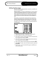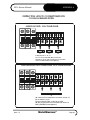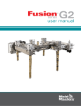
1
MZ-L
user manual
revision 1.3
www.moldmasters.com
AMENDMENT RECORD Mold-Masters® Users Manual
Issue
Date
0.0B
24/04/01
0.1B
Amendments
Author
Authorised
First Issue
DH
SK
11/09/01
Revised Issue
TJ
1.0
20/09/01
Revised Issue
DT
JN
1.1
25/03/02
Revised Issue
DT
JN
1.2
01/12/02
Revised Issue
DT
JN
1.3
01/01/06
Added voltage requirement for
external standby port
DT
JN
Copyright © 2001 Mold-Masters® Developments
This manual is intended for use with the MZ L-Series Controller
Our policy is one of continuous improvement and we reserve the right to alter product
specifications at any time without giving notice.
Page 2
Mold-Masters®
Issue 1.3
MZ L-Series Manual
Contents
Contents
AMENDMENT RECORD .................................................................................2
Contents ..........................................................................................................3
Specification ....................................................................................................4
Safety Instructions ...........................................................................................5
Welcome..........................................................................................................6
Installation........................................................................................................7
Switching "On" and "Off" ..................................................................................8
The LCD Console ............................................................................................9
The Controller Cabinet...................................................................................17
How the MZ Controller Works........................................................................19
Setting up your controller ...............................................................................21
Running your controller..................................................................................34
Customising your controller ...........................................................................41
Maintaining your Controller ............................................................................45
More options – 30A-Mod controller card and I/O card ...................................55
Servicing and repairing your controller...........................................................57
Troubleshooting .............................................................................................58
Spare Parts List .............................................................................................64
APPENDIX A .................................................................................................66
Glossary.........................................................................................................73
Index ..............................................................................................................74
Issue 1.3
Mold-Masters®
Page 3
Specification
MZ L-Series Manual
Specification
The following are general specifications. The actual controller supplied may differ in
specified options.
Supply Voltage:
380v 3 phase 50Hz with neutral, others available
220/60Hz Delta
Mains Voltage Output:
Burst fired, zero crossover and Phase Angle fired
Control Method:
Open or closed loop
Earth Leakage
Measurement
Earth leakage measurement on individual cards
(set at 10mA)
Overload protection:
Fast Blow Fuse
Thermocouple input:
Iron Constantan Fe/Con type 'J', Chromel/Alumel type
'K'.
Control range:
0 - 472 Centigrade (Celsius), 32 - 881 Fahrenheit
Temperature scale:
Centigrade (Celsius) or Fahrenheit
Card Diagnostics LED's
Scan, T/C Fault, load output, ground fault, and fuse fault
Printer output
connector
RS-232 serial, DB9 male connector
Alarm Output
Double-pole change-over volt-free contacts,
5A max burden
T/C Tool connector
Contact H-BE24BS Male
Heater Tool connector
Contact H-BE24SS Female
Keypad
4x4 matrix, tactile switch
Display
16 x 40 characters, 128 x 240 pixels LCD, CFL Back
Light
Case Details
Heavy duty metal cabinet
Page 4
Mold-Masters®
Issue 1.3
MZ L-Series Manual
Safety Instructions
Safety Instructions
DO NOT enter the cabinet without first ISOLATING the supplies –
there are unguarded terminals inside the cabinet which may have
a dangerous potential across them.
WARNING
Where a three-phase supply is used then this potential may be at
380 volts or higher.
Safety Notices - an explanation
Within this manual, safety instructions are marked as follows:
A WARNING symbol and message, shown here, identifies where
there may be a hazardous situation which, if not avoided, may
result in death or injury to personnel.
WARNING
CAUTION
Most warnings pertain to electrical aspects and you must comply
with them to minimise any personal danger.
A CAUTION warning identifies where there may be a hazardous
situation which, if not avoided, may result in damage to property.
Caution warnings present no personal danger, but may cause the
equipment to fail or lose its memory.
Issue 1.3
Mold-Masters®
Page 5
Welcome
MZ L-Series Manual
Welcome
Mold-Masters® welcomes you to their MZ range of temperature
controllers for hot runner injection moulding tools. This particular
member of the proven family of Mold-Masters® Hot Runner
Controllers is user friendly and retains the standard control
facilities associated with other Mold-Masters® controllers.
How to use this manual
The purpose of this manual is to give you a complete
understanding of how best to use the controller and to assist
where there are problems or faults.
The first part of this manual – “Introductory Tour” contains a brief
technical description of the system components and a portrayal of
the Mold-Masters® operating philosophy that facilitates precision
temperature control.
The following chapters then take you carefully through the stages
of setting up, and running, a new control system. After considering
system maintenance the final sections look at trouble shooting to
assist in the unlikely occurrence of a system fault.
Page 6
Mold-Masters®
Issue 1.3
MZ L-Series Manual
Installation
Installation
Where to use this equipment
Mold-Masters® Hot Runner temperature controllers are designed
for use in the plastic injection moulding industry as temperature
controllers for hot runner systems as commonly used in mould
tools. The controllers must not be used in residential, commercial
or light-industrial environments. Furthermore, they must not be
used in an explosive atmosphere or where there is a possibility of
such an atmosphere developing.
WARNING
They should be installed in a clean dry environment where the
ambient conditions do not exceed the following limits:
* Temperature
0 to +35°C.
* Relative Humidity
90% (non-condensing)
When in use this equipment does not emit audible noise in excess
of 10dbA.
Controller — Tool Connections
The various connections to the system using the cables supplied
with the equipment are specified in Appendix A.
Controller Power Supplies
The control cabinet can be manufactured to accept a wide range
of supplies and sequence of phases. Refer to the serial plate in
the controller cabinet for confirmation of the supply requirements.
If the local supply is outside the specified range please contact our
Service department for advice.
Tel.: (1) 905-877-0185
(1) 800-450-2270
Fax: (1) 905-873-2818
Issue 1.3
Mold-Masters®
Page 7
Switching "On" and "Off"
MZ L-Series Manual
Switching "On" and "Off"
The main Power Switch is a rotary Switch at the back of the
cabinet. This Switch is sufficiently rated to disconnect the total
load current during switch “On” and switch “Off”. You can use a
suitably- sized padlock, or similar device, to lock the switch in the
“Off” position to prevent operation during maintenance.
Although the main switch has the capacity to switch the whole
system “Off”, we recommend that you only do this in an
emergency situation. Your console and cabinet use computer
technology and you should normally switch the system off in
stages, as detailed below. A sequenced method for switching
“On” and “Off” protects the controller and keeps the switched load
to a minimum to extend the life of the main Isolator.
Switching On
Provided the Start option has been set to “Stop”, then switching
the main power switch to “On”, does not cause the zones to heat
up.
Once the main menu is available, you can select “Run” [3] from
the main menu to start heating the tool.
Switching Off (or Shutting Down)
We recommend that you use the controller to shut down the
heating load, and only use the main isolator to switch off the whole
system once it is idle.
1. Shut down the heating
On the Main Menu select Stop [2] mode to reduce the heating to
zero.
2. Shut down the Controller
Now use the Main Rotary Switch on the cabinet to isolate all the
power from the whole system.
Page 8
Mold-Masters®
Issue 1.3
MZ L-Series Manual
The LCD Console
The LCD Console – An Introductory Tour
This part of the manual introduces you to the LCD console to
show, briefly, what facilities are available and what information is
available.
7
8
9
4
5
6
1
2
3
CLR
0
ENT
Navigation
The LCD Screen displays all the necessary pages and the keypad
alongside provides you means of control. Most of the pages
operate in the same way, for instance:
•
•
•
to move between pages and for those pages where there is a
choice between different functions, enter the page or selection
number at the Function prompt and press [ENT]
to leave a page and save the modifications, press [ENT]
to leave a page without saving the modifications, press [CLR]
Status Line
At the bottom of the display is a status line, which indicates any
operational mode of the controller such as 'Run', ‘Standby’ or
‘Boost’.
Password Protection
System Password is [2] [▲] [▲] [▼]. Certain pages, or screens,
generally those which are related to configuring zones, setting limits
and zone operating modes, are protected by a password. To prevent
unauthorised changes, initial entry requires a system password for
access.
Once the password has been supplied then all protected menus are
available for the next 30 seconds. Also, this timer will reset when you
enter such a screen and not restart until you leave it. This means that
you can swiftly move from one protected screen to another within one
session. Once you have left any protected screen, and 30 seconds
have elapsed, then the protection becomes active once more.
Issue 1.3
Mold-Masters®
Page 9
The LCD Console
MZ L-Series Manual
Keypad
The standard keypad has 16 keys including 10 numeric keys (0 9), 4 arrow keys (up, down, left and right), an enter key (marked
ENT) and a cancel or clear key (marked CLR).
Number Keys: These enter a value or menu option (always
followed by the enter key).
Arrow Keys: These are used for display and tool store options.
The left arrow is used to correct entry errors. It erases the last digit
(up to the start of the field).
Enter Key: This key enters the command selected on the screen.
E.g. to enter a value or select a menu option.
Clear Key: If an entry is started the clear key erases the whole of
the entry. Pressing the clear key at the start of prompt returns the
user to the previous screen.
Front Panel Status Indication
There are three LED indicators to show the status of the
controller:
• Green Controller is operating normally.
• Amber One or more zones are outside of the set limits.
• Red
A fault has been detected such as thermocouple failed
or system error, and so the controller is in alarm.
Page 10
Mold-Masters®
Issue 1.3
MZ L-Series Manual
The LCD Console
The LCD Screen
The ‘Home’ screen for the Console is the only screen that will
show two boxes of data with a total display of 24 zones.
Displayed Data
The display within each box shows:
Zone
Set
Act
Power
Zone
Identifier
Shows:
- Set temperature
when in Auto.
- Set power level
when in manual,
- and "Sn" if slaved
to Zone "n".
Shows:
- actual measured
temperature when
in Auto,
- % power in
manual
- and Error
messages when
they occur.
Shows Power level
that is being supplied
to maintain the
current temperature.
Using the arrow
[Í]/[Î] keys toggles
this display to "ground
current".
Showing further Zones
If more than twenty-four zones have been configured to the
controller then you can use the [▼] and [▲] arrows on the keypad
to scroll down or up to display them.
To access Main Menu
To gain control access Press [ENT] to reveal the Main Menu.
Issue 1.3
Mold-Masters®
Page 11
The LCD Console
MZ L-Series Manual
MZ Operation Block Diagram
Page 12
Mold-Masters®
Issue 1.3
MZ L-Series Manual
The LCD Console
Main Menu options
There are 6 options available on the Main Menu, which are
described in the following pages.
Run, Stop, Standby and Boost
Main Menu options 1-4 are immediate function options that put the
controller into each particular working mode.
Issue 1.3
Mold-Masters®
Page 13
The LCD Console
MZ L-Series Manual
Set Zone(s) Menu
The ‘Set Zone(s)’ Menu is used to fix any one zone's temperature.
It offers the following features:
•
Set Zone is used to change any of the zones individually
•
Set Zones is used to set a group of zones to the same set
point.
•
Inc Zones is used to increase the temperature on a group
of zones.
•
Dec Zones is used to decrease the temperature on a
group of zones.
This operation is fully described on page 25 in the "Setting Up"
Chapter.
Utilities
The ‘Utilities’ option allows you to set up many of the variables in
your controller according to different tool requirements.
Page 14
Mold-Masters®
Issue 1.3
MZ L-Series Manual
The LCD Console
Graph
The ‘Graph’ option allows you to select any zone, in order to
display its recent temperature performance over the last 5 or 30
minutes.
Tool Set
The ‘Tool Set’ option gives access to a store for up to 10 different
tool settings which you can use at any time.
Configure
The ‘Configure’ option allows you to set up many of the variables
in your controller according to different tool requirements.
Issue 1.3
Mold-Masters®
Page 15
The LCD Console
MZ L-Series Manual
Print Reports
The ‘Print Report’ option allows you to print out both current and
stored tool settings to a connected printer.
Engineering
The ‘Engineering’ section falls into two main areas as seen below:
Page 16
•
the first four options allow you to set up and run diagnostic
health check routines on your system
•
the last five options are a few extra facilities that are needed
during preliminary setting up for different tools
Mold-Masters®
Issue 1.3
MZ L-Series Manual
The Controller Cabinet
The Controller Cabinet
The power supply to the control cabinet is via a bulkhead mounted
3-pole plug wired in star or delta configuration. (Please check your
specification for details of which configuration has been supplied.)
Connections to the tool are by looms terminating in Contact HBE24 connectors. Wiring details are shown in Appendix A.
An alarm input and output connector is available for extending the
alarm or, perhaps, inhibiting the injection process.
A serial printer port is provided for producing hard copies of
certain screens. Again, please check with the system
specification for details.
Controller Cards
The main controller cards are four-zone modular cards that provide
real time temperature control.
These are all standard 6U euroboard size, with two DIN connectors,
and are mounted in a single rack which may take up to a maximum of
6 cards.
Each card has three main components:
• thermocouple amplifiers,
• CPU,
• multi-voltage output triacs.
Thermocouple Amplifiers
The thermocouple amplifiers have preset responses for both J and
K type thermocouples. The selection of Sensor type on the
Utilities Menu sets a flag that is read by the control card; this in
turn sets the differential amplifier to match the selected
thermocouple type.
Issue 1.3
Mold-Masters®
Page 17
The Controller Cabinet
MZ L-Series Manual
Central Processor Unit (CPU)
The CPU provides the following facilities:
• closed and open loop control of the zones,
• communicates settings and thermocouple readings over the
data link to the display micro-processor
• checks for alarm conditions, including blown output fuse(s),
incorrect thermocouple wiring, zone over temperature
condition, heater not responding to controller output and
generates alarm information for the display screen and alarm
relay (if fitted),
• controls the output power to the on-board triacs using a
number of self-tuning algorithms,
• controls a row of diagnostic LED’s mounted on the edge of the
controller cards. These LED’s can be seen through the window
in the faceplate of the controller.
• monitors the thermocouple every 20 milliseconds
Phase angle firing is normally used for power control. However on
heavier loads such as manifolds, the control card will
automatically switch over to burst-fire control once the load has
warmed up.
The card requires no analogue calibration and is ready for use
once set up from the display console.
Output Triacs
The controller card is fitted with four on-board triacs that are capable of
controlling heating loads of up to 15 Amps peak.
Power Supply Units (MMPSU25)
A separate power supply is provided for the cards, data
communications and an alarm output relay.
Page 18
Mold-Masters®
Issue 1.3
MZ L-Series Manual
How the MZ Controller Works
How the MZ Controller Works
Mold-Masters® controllers are designed to perform in closed and
open loop configurations. However, we consider that the normal
operating mode is closed loop.
Whenever the controller is set to start, the system goes into a selfcalibration routine. This is illustrated in the following diagram and
explained below.
Set Point
Temperature
5
4
Load
Test
3
2
Soft
Start
Load Test Delay
1
Time
1. The zone controller slowly ramps up the heater power and
simultaneously looks for a positive temperature change at the
thermocouple input. The controller verifies the actual rate of rise
against a predetermined value. Power is slowly increased until the
correct rate of rise is achieved.
2. The controller now increases the zone temperature at a constant rate
of rise until the temperature reaches about 110°C (230°F).
3. At 110°C the controller performs a 'Load Test' on the zone heater
to check its thermal characteristics. The output power is reduced
to zero for a test period and the temperature monitored for a
response. From all this information, the controller builds a
mathematical model of the heater characteristics so it can
automatically select a Fast, Medium or Slow response-heating
program that suits the tool. This allows more efficient control of the
zones.
4. The controller continues to ramp up the temperature to the set
point, which should be achieved with minimum over-shoot.
5. Having built a virtual model to map the tool and heater
characteristics, the controller can maintain the temperature at an
accurate point with virtually no deviation.
Issue 1.3
Mold-Masters®
Page 19
How the MZ Controller Works
MZ L-Series Manual
Watchdog feature
The Controller card CPU has a 'watchdog' timer that has to be
reset by the system every 3 milliseconds. If for any reason the
software fails to reset the timer, the program is reset to the start
position, which initialises the controller and so protects the tool
from over-heating. The card resumes control of the zone from the
start position.
Safety Memory Check
This controller uses RAM, with a battery back up, to store all your
settings such as zones, types, temperatures, limits and tool bank
settings. There is an extremely low small risk that an interruption
may cause any of these settings to alter and, if such an event
should occur, there must be no risk to the equipment. If a zone
had previously been set to, say 260 deg, should become
corrupted to, perhaps 520 deg, then the controller must not
attempt to establish the incorrect temperature upon the next startup command.
To ensure this cannot happen, there is a safety memory-check
facility. This checks to see that no value has been changed since
the last time the controller was used. If this facility detects any
setting is different, then it protects your system by automatically
erasing every single stored setting within its memory. If such a
rare occurrence happens to your controller you will be met by the
following screen when you switch it on:
If you see this screen, you will need to go through all the various
screens and input all appropriate settings. This basic task is
described in the "Setting Up" section of this manual. The task is
easier if you have all the correct settings written down in a safe
place.
CAUTION
Page 20
Mold-Masters® recommends that a hard copy of all the controller
and tool settings be saved in a safe place.
Mold-Masters®
Issue 1.3
MZ L-Series Manual
Setting up your controller
Setting up your controller
New MZ series controllers are correctly configured at the factory
and you should not need this section for a new system. However,
if you reconfigure your controller to a new tool or environment, you
may well need this chapter of the manual.
This initial set up is detailed here in easy-to-follow steps that help
you to become familiar with your new equipment.
What is covered in this section
How the system automatically selects temperature
range
Setting your preferred temperature display
Configuring the controller to your tool
Setting zone types
Matching sensor types
Setting the required temperatures
Selecting the Master Zone
Setting boost values
Setting alarms and limits
Checking your initial settings
Saving your initial settings
Issue 1.3
Mold-Masters®
Page 21
Setting up your controller
MZ L-Series Manual
Automatic temperature-range selection
The MZ has an automatic function that establishes the
temperature scales. It works by detecting the supply frequency
and sets the temperature scale to centigrade on 50 Hz supplies
and Fahrenheit for 60 Hz supplies
This automatic setting means that the temperature is displayed in
degrees Fahrenheit in America and degrees Centigrade in most
European countries. There are, however, some countries that
have different parameters, for instance Brazil uses Centigrade but
has 60 Hz supplies. Should this situation arise you can change the
system temperature scale to a preferred range.
Setting the temperature display
Where the automatic detection shows the temperature as
Centigrade rather than Fahrenheit (or vice versa) then you can
easily change it.
From the main menu:
1. Select Utilities [6] > Engineering [5] > Temp Scale [7]
2. Enter the system Password
3. Enter a value to indicate your preferred temperature range:
[0] for ‘Degrees Centigrade’
[1] for ‘Degrees Fahrenheit’
4. Press [ENT] to confirm your choice.
Page 22
Mold-Masters®
Issue 1.3
MZ L-Series Manual
Setting up your controller
Setting the Zone types
Each zone must be configured either as a probe or manifold, and
set to the correct speed.
Response Speed: Our experience at Mold-Masters® is that the majority
of probes show satisfactory behaviour if you select ‘Auto’ for response
speed. Some probes may require a faster response time and this may
become apparent if the probe tends to run cooler than desired. If this
happens then a ‘Fast’ response improves the situation. Large masses
such as manifolds may require slowing down by selecting Medium or
Slow.
More recently, a new generation of probes that are even faster have
made their appearance and so we have added ‘Ultra’ response times
which are correspondingly faster in their response time. To date, very
few controllers have required this ultra –fast setting... If your tool does
need them, you may select settings 4 which are all faster equivalents to
the normal range.
1. Select Utilities menu [6] > Configure [3] > Zone Type [1]
2. At the ‘Password?’ prompt, enter the password
3. At the ‘Start?’ prompt, enter the zone number for the first zone
in your target group and press [ENT]
4. At the ‘End?’ prompt, enter the zone number for the last zone
in your target group and press [ENT]
5. At the ‘Type?’ prompt, enter the type of zone and press [ENT]
6. At the ‘Speed?’ prompt, enter the desired response speed and
press [ENT]
7. Repeat steps 1 to 6 for the other Zone types (manifold, and
cycle synchronised)
Issue 1.3
Mold-Masters®
Page 23
Setting up your controller
MZ L-Series Manual
Matching sensor types
There are two different types of probe sensors, J type and K type,
with different characteristics. Control cards use differential
amplifiers with dual settings in order to respond correctly to either
type.
Your choice of thermocouple type at this screen sets a flag that is
read by the control card. However, the sensor type is normally
configured to a J-Type before leaving the factory and should only
need to be altered in rare circumstances.
1. Select Utilities menu [6] > Configure [3] > Sensor Type [2]
2. Enter the password
3. At the ‘Start?’ prompt, enter the number of the first zone in your
target group and press [ENT]
4. At the ‘End?’ prompt, enter the number of the last zone in your
target group and press [ENT]
5. Enter
[0] for Type J
[1] for Type K
and press [ENT]
Page 24
Mold-Masters®
Issue 1.3
MZ L-Series Manual
Setting up your controller
Setting the required temperatures
When you first set up your controller you must consider:
• which channels will be Probe, Manifold,
• whether they will operate in Closed Loop (Auto) Mode, Open
Loop (Manual) Mode or Slaved to other channels.
• what will be your required operating temperature or power
settings.
Setting one Zone at a time (Probes and Manifolds)
Your can set up one channel at a time by using the ‘Set Zone’
command from the Main Menu.
1. At the Main menu select Set Menu [5] > Set Zone [1].
2. On the ‘Zone?’ prompt, enter the zone number that you are
configuring and press [ENT].
3. Use [◄], [►] to select P (Probe) or M (Manifold) and press [ENT].
4. Next, at the ‘Temp?’ prompt, the system defaults to ‘Auto’
mode.
5. If AUTO is not your preferred mode, then press [ENT]
repeatedly to step though ‘Manual’ and ‘Slave’, and back to
‘Auto’. As you step through these modes then you see the
prompt change to ‘Power?’, ‘Slave?’ and back to ‘Temp?’
Once you are in your preferred Mode enter the required
Temperature, Power Setting or Slave Channel as appropriate
and press [ENT] to establish your choice.
6. Repeat Steps 1 – 5 for any other zones.
Issue 1.3
Mold-Masters®
Page 25
Setting up your controller
MZ L-Series Manual
Setting several Zones together
If you have a number of channels that need common settings, such as
probes, then it is easier to establish their settings as a group.
1. At the Main menu select Set Zone(s) [5] > Set Zones [2].
2. At the ‘Start?’ prompt enter the number of the first zone in the
group and press [ENT].
3. Use [◄], [►] to select P (Probe), M (Manifold) and press
[ENT].
4. At the ‘End?’ prompt enter the number of the last zone in the
group and press [ENT].
5. Next, at the ‘Temp?’ prompt, the system defaults to ‘Auto’
working.
6. If this is not your preferred mode then press [ENT] repeatedly
to step though the Modes: ‘Manual’, ‘Slave’, and back to
‘Auto’. As you step through these modes then you see the
prompt change to ‘Power?’, ‘Slave?’ and back to ‘Temp?’
Once you are in the preferred Mode, then enter your required
Temperature, Power Setting or Slave Channel as appropriate
and press [ENT] to establish your choice.
Page 26
Mold-Masters®
Issue 1.3
MZ L-Series Manual
Setting up your controller
Setting the Master Zone
The "Run" command normally uses an auto-selected "Master
Zone" to regulate the heating of faster Probes. During "Run", the
main controller over-rides all the Probes’ normal “Set”
temperatures and substitutes them with the Manifold "Actual"
temperature. By doing this the faster responding probes are held
back to follow the slower-rising manifold temperature. The results
of this programming mean that the whole tool warms up in a
homogenous manner.
By selecting this "Master Zone" screen you can over-ride the
controller’s automatic selection of manifold zone to some other
zone that you may consider more appropriate. You may also use
this screen to completely de-select any Master Zone so that all the
zones can warm-up in their own time without any probes being
held back to follow a slower manifold. MZ uses manifold1 [1M] as
the default master zone.
Issue 1.3
1.
From the Main Menu select Utilities [6] > Engineering [5] >
Master Zone [9].
2.
Enter the System Password.
3.
At the Master Zone prompt enter the zone number for your
preferred manifold - or
4.
Enter a 0 (zero) if you wish to de-select any master zone and
enable faster probe warm-up times.
5.
Press [ENT] to put your selection into memory and return to
the Engineering Menu.
Mold-Masters®
Page 27
Setting up your controller
MZ L-Series Manual
Setting Boost Values
Before you can use ‘Main Menu > Boost [4]’ you must first
configure the amount, and period of boost heat. These two
parameters are configured separately, as described below.
Boost Temperature
1. From the Main Menu Select Utilities [6] > Configure [3] > Boost
Value [4].
2. Enter the System password.
3. At the ‘Increase?’ prompt enter the degree rise required and
press [ENT].
Boost Time
1. From the Main Menu Select Utilities [6] > Configure [3] > Boost
Time [5].
2. Enter the System password.
3. At the ‘Max.Time?’ prompt enter the Boost Time (calculated in
seconds) and press [ENT].
Page 28
Mold-Masters®
Issue 1.3
MZ L-Series Manual
Setting up your controller
Standby Delay
The time in seconds to activate the standby feature (reduce 50’C
below the set temperature.)
1. From the Main Menu Select Utilities [6] > Engineering [5] >
Standby Delay [6].
2. Enter the System password.
3. At the ‘New?’ prompt enter the required delay (in seconds) and
press [ENT].
Console Alarms
Your Mold-Masters® Controller has three LEDs on the front panel
to advise you about the condition of the tool and controller.
Green ‘Normal’-the controller is working normally
Amber ‘Warning’-One or more zones are outside their limits.
Red
‘Alarm’-A fault has been detected such as thermocouple
failed, System Error or Temperature out of limits failed and so the
controller is in alarm.
Deferring alarms
Where a ‘Temperature Limits’ Alarm output option has been fitted,
then you can disable it for a set period of time. This allows the tool
to reach its correct operating temperatures without raising a
spurious ‘out of limits’ alarm.
Issue 1.3
Mold-Masters®
Page 29
Setting up your controller
MZ L-Series Manual
1. From the Main Menu select Utilities menu [6] > Engineering [5]
> Alarm Delay [5].
2. Enter the password.
3. At the ‘New?’ prompt enter the required delay (in minutes) and
press [ENT].
Disabling alarms
You can totally disable the Alarm Output by entering a value of
‘99’ for the delay period.
1. From the Main Menu select Utilities menu [6] > Engineering [5]
> Alarm Delay [5].
2. Enter the password.
3. At the ‘New?’ prompt enter 99 and press [ENT].
Monitoring temperature limits
Your controller looks at the actual temperature of all the zones
and verifies that the tool is operating within specific limits. Rather
than fixed points of temperature, the Hi and Lo limits are set to
degrees above and below the set point. This provides an alarm
window that moves with the set point.
Page 30
Mold-Masters®
Issue 1.3
MZ L-Series Manual
Setting up your controller
1. From the Main Menu select Utilities [6] > Configure [3] > Limits
[6].
2. At the ‘New Hi?’ prompt enter the ‘degrees above set point’
upper limit and press [ENT]
3. At the ‘New Lo?’ prompt, enter the ‘degrees below set point’
lower limit and press [ENT]
After both have been entered the controller returns to the main
display and the limits are displayed at the bottom of the screen.
Maximum power limits
If your controller is to be run in open-loop mode, then you can limit
the maximum percentage power that is applied to any zone. This
option prevents damage by not overheating the tool when the
machine is running in open-loop mode.
1. From the Main Menu select Utilities menu [6] > Configure [3] >
Power Limit [3].
2. At the ‘Maximum?’ prompt enter your required maximum
percentage power and press [ENT]
Issue 1.3
Mold-Masters®
Page 31
Setting up your controller
MZ L-Series Manual
StartUp Mode
This determines how your controller activates the system when
the main Isolator is first switched on. There are two options
available:
•
‘Run’ —
the controller applies voltage to the heaters and the
zones rise up to their preset operating temperature.
•
‘Stop’ —
the controller is idle and the zones are set to Zero
temperature. The operator then needs to select
"Run" on the front panel to start heating the tool.
To select either of these modes:
1. From the Main Menu select Utilities [6] > Engineering [5] >
StartUp Mode [8].
2. Enter the password.
3. At the ‘Mode?’ prompt enter [0] for ‘Run’ or [1] for ‘Stop’ and
press [ENT].
How to verify your tool settings
One screen enables you to check how the controller is currently
set up. The area on the left displays shared settings, such as
Boost and Temp Scale. The table on the right shows individual
settings — channel modes, on or off-board triac, type of sensor
and power display.
1. From the Main Menu select Utilities [6] > Configure [3] > Show
Settings [7].
Look through the displayed current settings to see everything is
set as required.
Page 32
Mold-Masters®
Issue 1.3
MZ L-Series Manual
Setting up your controller
How to save your tool settings
Once you have configured the controller to operate as you require,
it is good practice to save the settings to avoid having to repeat all
these steps. There is a memory bank that can store, and recall, up
to 10 different combinations of power, zone and alarm settings.
This page only describes how to save your immediate settings,
however all the tool store features are fully explained in the
Customising chapter.
To Name the Tool
1. From the Main Menu select Utilities [6] > Tool Set menu [2] >
Name a Tool [1].
2. At the ‘Tool No?’ prompt choose an empty row and press
[ENT].
3. Enter a suitable and brief name for this tool setting. You can
use the arrow keys to select letters, and symbols, while
numbers can be entered directly from the keypad
4. Once you have completed the Tool Store name, move the
flashing cursor to ‘END’ and press [ENT].
5. At the next ‘Tool No?’ prompt press [ENT] to confirm the new
name.
To Save the Tool
1. From the Main Menu select Utilities [6] > Tool Set menu [2] >
Save Settings [2].
2. Enter the tool number that corresponds to the tool that you
have just named.
3. Press [ENT] to confirm your choice or [CLR] to cancel it and
return to the Tool Set menu.
Issue 1.3
Mold-Masters®
Page 33
Running your controller
MZ L-Series Manual
Running your controller
‘Running your controller’ is concerned with everyday use of the
controller for normal production use. This is considered as
selecting an appropriate run mode for the machine according to
whether the tool is working or waiting. It may also be necessary to
make changes to the heater temperatures and using the graphical
display of recent performance, may help such decisions.
What is included in this section
Starting
Stopping
Pausing
Boost – how to apply a short increase
Raising and lowering set temperatures
Using ‘Slave’ Mode to compensate for a failed
thermocouple
Looking at temperature history for the last 5 or 60
minutes
Page 34
Mold-Masters®
Issue 1.3
MZ L-Series Manual
Running your controller
Starting, Stopping and Pausing
How "Run" works…
The Mold-Masters® controller is preset to self-select one of the
manifold zones to be a "Master Zone". During Start-up, power is
applied to all zones, but the target temperature for the faster
Probes is set to follow the actual temperature of the master
manifold. The manifold has a slower heat rise time than the
probes and the result is a uniform temperature rise across the
whole tool.
However, if a homogenous rise is not required, there is the option
to de-select the Master Zone in the Engineering menu. Doing this
would mean that all the zones reach their set operating
temperature in their own time, in which case the Probes would be
quicker to reach their normal operating temperature.
De-selecting a Master Zone controlled Start-up
1. From the Main Menu select Utilities [6] > Engineering menu [5]
> Master Zone [9].
2. Enter the Password.
3. On the ‘Manifold?’ prompt, enter [0] press [ENT] to return to
the Engineering Menu.
Run Mode
1. From the Main Menu select Run [1] and press [ENT] to
confirm.
Stop Mode
1. From the Main Menu select Stop [2] and press [ENT] to
confirm.
Standby Mode
This mode is available for times when the mould-tool is paused. In
this condition, all the probe temperatures are reduced by 50°C.
This helps to prevent degradation on certain materials. Meanwhile
the manifold is maintained at its normal operating temperature to
allow a fast restart.
1. From the Main Menu select Standby [3] and press [ENT] to
confirm.
Issue 1.3
Mold-Masters®
Page 35
Running your controller
MZ L-Series Manual
Boost Mode
Boost Mode provides a means of temporarily boosting the Probe,
or Probe Tip, temperature. To determine how much rise and for
how long it is applied, refer to the ‘Setting Boost Values’ on page
28.
1. From the Main Menu select Boost [4] and press [ENT] to
confirm.
To Raise and Lower Operating Temperatures
If you need to increase, or decrease, the set temperature for one or
more zones, then two commands, within the Set Zone(s) menu, are
available for you to use.
Inc Zones
This allows you to select a group of zones and uniformly increase
their set temperature by the same value.
1. From the Main Menu select Set menu [5] > Inc Zones [3].
2. At the ‘Start?’ prompt enter the number of the first zone in your
target group and press [ENT]
3. Use [◄], [►] to select P (Probe) or M (Manifold) and press
[ENT].
4. At the ‘End?’ prompt enter the number of the last zone in your
target group and press [ENT].
5. At this step you have the opportunity to switch from ‘Auto’ to
‘Manual’ mode, and back, by repeatedly pressing [ENT]. The
chosen mode is shown by the prompt that changes between
‘Temp?’ and ‘Power?’.
6. While on your preferred mode, enter the desired temperature
or power increase and press [ENT].
7. At this stage you can press [ENT] or [CLR] to confirm your
command, and return to the Set Zone(s) menu.
Page 36
Mold-Masters®
Issue 1.3
MZ L-Series Manual
Running your controller
Not every zone will, necessarily, be affected!
Be careful if you have your controller set up with a mixture of
zones, i.e. some in Auto, some as Manual. At step 5 above, the
selection of Auto or Manual constrains your selection to only those
channels that are of the same configuration.
For example,
Zones in
“Auto”
Zones in “Manual”
Before changing
At 200° in Auto
At 50% in manual
After choosing 20°
C Rise
Rises to 220° C
Stays at 50% power
applied
After calling for 5%
power increase
Stays at 200° C
Rises to 55% power
applied
The same principal applies to both “Inc” and “Dec” commands.
Issue 1.3
Mold-Masters®
Page 37
Running your controller
MZ L-Series Manual
Dec Zones
This allows you to select a group of zones and uniformly
decrease their set temperature by the same value.
1. From the Main Menu select Set Zone(s) [5] > Dec Zones [4].
2. At the ‘Start?’ prompt enter the number of the first zone in your
target group and press [ENT].
3. Use [◄], [►] to select P (Probe) or M (Manifold) and press
[ENT].
4. At the ‘End?’ prompt enter the number of the last zone in your
target group and press [ENT]
5. At this step you have the opportunity to switch from ‘Auto’ to
‘Manual’ mode, and back, by repeatedly pressing [ENT]. The
chosen mode is shown by the prompt that changes between
‘Temp?’ and ‘Power?’.
6. While on your preferred mode, enter the desired temperature
or power decrease and press [ENT].
7. At this stage you can press [ENT] or [CLR] to confirm the
command, and return to the Set Zone(s) menu.
Page 38
Mold-Masters®
Issue 1.3
MZ L-Series Manual
Running your controller
Using ‘Slave’ Mode to compensate for a failed
thermocouple
If a thermocouple fails while the controller is working then you may
see different results. A complete fail shows a ‘T/C’ error message
against the actual zone and the actual temperature falls off to
zero. Sometimes it may be intermittent in which case it may show
as uncontrolled temperature deviations for the concerned zone.
Your prime aim is to compensate for this condition and maintain
production until the machine is free and the fault can be repaired.
Slave mode allows you to disregard the particular thermocouple
and slave the faulty zone to work to another zone which is healthy.
This master zone then controls the temperature for the faulty
slaved zone.
1. From Main Menu select Set Menu [5] > Set Zone [1]
2. At the Zone? prompt, enter the number of the zone which has
the failed thermocouple.
3. Use [◄], [►] to select P (probe) or M (Manifold) and press
[ENT].
4. Press the [ENT] button sufficient times until you get the Slave?
Prompt.
5. Enter the number of another healthy zone that is currently
working to the same set temperature as that which you require
for the faulty zone and press [ENT].
Note – ‘Conditions for slaving zones’:
You must select a healthy zone to slave on to. For instance, if
Zone 3 is already slaved to Zone 6 and you now wish to slave
Zone 2, then you might not select Zone 3 as a master zone.
You must choose any other healthy zone, and this includes
Zone 6, which is currently selected as a master zone for Zone
3.
6. The ‘Actual’ column for the slaved zone now shows ‘S n’,
where ‘n’ is the number of the zone that you have slaved to.
Issue 1.3
Mold-Masters®
Page 39
Running your controller
MZ L-Series Manual
Any subsequent changes (for instance, temperature changes)
that are made to the master zone, affect the slaved zone also.
Check zone performance (graph)
Your controller can record and display the temperature history for
any zone over a period of time. In this model, there is the option to
view a historical graph for the last 5 minutes or the last 60
minutes.
1. From the Main menu select Utilities Menu [6] > Graph [1].
2. At the ‘Zone?’ prompt enter which zone you want to view and
press [ENT].
3. Use [◄], [►] to select P (Probe) or M (Manifold) and press
[ENT].
The temperature/time graph now displays how that chosen zone
has behaved over the last 5 minutes and the legend at the bottom
shows further options. At this point you may:
Page 40
•
Press [ENT] to toggle the time viewed between 5 minutes and
60 minutes
•
Use the [▲] and [▼] keys to toggle between X1 and X2
temperature scale
•
Use the [◄] and [►] keys to move the viewed temperature
window up and down the scale
•
Press [CLR] to exit the viewed graph and return to the ‘Zone?’
prompt. At this stage you can select another zone to view or
press [CLR] or [ENT] to return to the Main Menu.
Mold-Masters®
Issue 1.3
MZ L-Series Manual
Customising your controller
Customising your controller
Your controller has a dedicated Tool Bank which enables you
adapt it quickly to different circumstances. It has ten available
positions that can be individually named, saved and recalled
whenever the tool or job changes.
Our convention is that new tool settings must have a name. If you
try to save a tool setting to an empty position that you have not yet
named, then the machine does not accept your request. To
amend this situation you must go back and name the tool position
then load it with your new settings.
What is included in this section
Inspecting the tool store – looking at what has
been saved
Naming a tool – creating a new tool position
Saving tool settings – putting settings into a new
tool position
Recalling tool settings – reusing past tool settings
that have been saved
Changing tool settings – altering existing tool
settings
Deleting a tool – how to clear a tool position
Issue 1.3
Mold-Masters®
Page 41
Customising your controller
MZ L-Series Manual
What is in the tool store?
You can see what tools are available, and which are in use, by
selecting from the Main Menu Utilities [6] > Tool Set [2]. The
display then shows you:
Page 42
Tool:
The number of the tool position. One of the positions is
marked with an asterisk (*) which indicates which tool
settings are currently loaded into the system.
Name:
The name that you have given to each tool position.
Set:
Any tool position that has settings saved in it shows a Y
in this position. Blank positions that have been named,
but contain no information, have no indication in this
column.
Mold-Masters®
Issue 1.3
MZ L-Series Manual
Customising your controller
Naming a tool
To give a name to a particular tool position:
1. From the Main Menu select Utilities [6] > Tool Set [2] > Name
a Tool [1].
2. At the ‘Tool No?’ prompt enter the number of a blank tool
position and press [ENT]
3. To create the name, use the [arrow] keys to select each letter
in sequence and the [ENT] keys to put that letter, or symbol,
into the new name. You can enter numbers directly by using
the keypad. As characters are added, then the new name is
displayed at the bottom of the screen.
4. When you have created an acceptable tool name, move the
cursor to the ‘END’ and press the [ENT] key to put the new
name into the tool position and return to the Tool Menu.
Saving tool Settings
Tool settings can be saved at any time into a named tool position.
CAUTION
If the selected tool store already holds a tool setting then the act of
saving into that slot causes the old settings to be overwritten and
lost. Therefore, always make sure that you select the right Tool
Store for new settings.
1. From the Main Menu select Utilities [6] > Tool Set [2] > Save
Settings [3].
2. At the ‘Tool No?’ prompt enter the Tool number that indicates
your chosen name/position and press [ENT].
3. Confirm your decision by pressing [ENT] to confirm or [CLR] to
exit without saving the new settings.
Issue 1.3
Mold-Masters®
Page 43
Customising your controller
MZ L-Series Manual
Recalling tool settings
Once settings have been saved to the controller then they may be
instantly recalled as follows:
1. From the Main Menu select Utilities [6] > Tool Set [2] > Load
Settings [4].
2. At the ‘Tool No?’ prompt enter the number of the tool that you
wish to load to your controller and press [ENT].
3. Confirm your decision by pressing [ENT] to confirm or [CLR] to
exit without loading the new settings.
NOTE:
If you select a tool that has no settings in its memory
then you are prompted to press [CLR] to exit the menu.
To change to another tool that has settings, start again at
step 1.
Changing tool settings
CAUTION
To permanently change a tool’s settings, this procedure saves
new settings to a tool position and over-writes any that are already
there. Once you have done this then previous settings in the
nominated position cannot be recovered.
1. Adjust the settings using appropriate menus and tools.
2. From the Main Menu select Utilities [6] > Tool Set [2] > Save
Settings [3].
3. At the ‘Tool No?’ Prompt enter a number which corresponds to
the tool which you want to change and press [ENT].
4. Confirm your decision by pressing [ENT] to confirm or [CLR] to
exit without saving the new settings.
Deleting a tool
CAUTION
Once you have deleted a tool there is no way to recover its previous
settings. Take care that you are deleting the correct tool.
To remove a tool and all its settings from any position:
1. From the Main Menu select Utilities [6] > Tool Set menu [2] >
Delete a Tool [2].
2. At the ‘Tool No?’ prompt enter the number of the tool that you
wish to delete and press [ENT].
3. Confirm your decision by pressing [ENT] to confirm or [CLR] to
exit without saving the new settings.
Page 44
Mold-Masters®
Issue 1.3
MZ L-Series Manual
Maintaining your Controller
Maintaining your Controller
Maintaining your controller considers how you look after your
machine. It includes electrical functional testing that may be
carried out as either preventative or fault-finding maintenance. It
also considers the physical aspects of maintenance and lists
those routines that can extend the useable lifetime of your
machine.
What is included in this section
Printing tool settings for the records
Running a self-diagnostic test – check that all is
functioning correctly
Viewing and printing test results – saving
diagnostic test results
Servicing and repairing your controller
Issue 1.3
Mold-Masters®
Page 45
Maintaining your Controller
MZ L-Series Manual
Printing tool settings
If you want a hard copy of any tool settings then your controller
can do this for you. The print facility enables you to print the
complete tool settings for any tool that may be:
• in the tool bank but not in current use
• in current use but changed
• the stored settings for the tool that you are currently using
(which may be different to the actual settings if you have
changed them since loading the tool).
In every case, the printout is sent directly to your connected
printer. If, however, no printer is detected, then the controller
reverts to normal working after approximately 10 seconds.
Current status:
This option prints out your control settings, as they are currently
set.
1. From the Main Menu select Utilities [6] > Print Reports [4] >
Current Status [1].
Current tool:
This choice prints out the settings for the tool that is currently
selected. They may be different to the Current status if any
settings have been modified since the tool was loaded:
1. From the Main Menu select Utilities [6] > Print Reports [4] >
Current Tool [2].
Database Tool:
This final choice prints out the tool settings for any other tool that
you have stored in your tool bank that you are not currently using.
1. From the Main Menu select Utilities [6] > Print Reports [4] >
Database Tool [3].
2. At the ‘Tool No?’ prompt, enter the number of the tool which
you want to print out and press [ENT].
Page 46
Mold-Masters®
Issue 1.3
MZ L-Series Manual
Maintaining your Controller
Self Diagnostic Tests
What is tested during a self-diagnosis check?
The Mold-Masters® Controller has a diagnostic-testing tool that
allows you to check that every zone is functioning correctly. The
routine may be used:
• as an acceptance check
• to see that a new tool is wired up correctly
• as a maintenance aid, to check that a working tool is
functioning correctly.
This routine allows the controller to step through all the zones,
heating one at a time and checking that appropriate heat rises are
detected. The following describes the tests and shows what is
deemed as a pass. It also describes some errors that may result
in ‘Failures’ or ‘Warnings’.
1. Once a test has been initiated the display returns to a main
screen and messages are displayed to keep you informed
about progress.
2. Initially the whole tool is cooled, so that it can start from a
stable environment, and then starts to run, sequentially,
through each zone.
3. The main screen displays a message ‘COOLING STAGE’, and
the first zone displays ‘TEST’ in the ‘Act’ column. During the
cooling, all zones are checked to see that none experience a
significant temperature rise.
4. After a period of time the main screen displays a message
‘POWER TEST’, and the ‘Set’ column for the zone under test
shows a quantity of percentage power that is applied to the
zone under test. While this is happening, it monitors every
other zone to see that only the zone under test experiences a
temperature rise. If no temperature rise is detected for the
zone under test, it increases the applied power and looks once
more for a heat rise. It continues this cycle of raised power and
monitoring, until it reaches the ‘count’ number of times,
stipulated in the ‘Test Defaults’.
5. Provided that the zone under test rises by an appropriate
degree, that zone is deemed to have passed the test. The
message “OK” is displayed and the controller moves on to the
next zone.
6. If, however, the controller fails to detects an appropriate heat
rise in the zone under test then it may have detected one of
two possible errors:
Issue 1.3
Mold-Masters®
Page 47
Maintaining your Controller
MZ L-Series Manual
a) if another zone exceeds the “Max Rise”, rather than the one
under test, it indicates that there is a crossover somewhere
between a probe and its thermocouple. In this case the test
sequence displays a “FAIL” message in the status line for the
zone under test.
(Note, if there is a crossover then you should expect to see a
second FAIL message to show with which other zone the
wiring is crossed.)
b) if the zone under test exceeds the “Max rise”, but a significant
heat rise is also detected in other zones, such that they
exceed the “Min Rise”, then the controller displays a ‘WARN’
message. (These other zones are physically close to the zone
under test, but not necessarily numerically adjacent.) This
fault is usually caused by excessive thermal conduction, which
impedes accurate temperature sensing, and so results in
imperfect temperature control.
At the end of the Tool Test, the system stores and displays all the
results. The particular incidences described above are displayed
in further detail. For instance, the two zones, which displayed
“FAIL” because of crossover, both show a full message
‘Heater/TC Common with Zone NN?’. The second incident,
which detected thermal conduction and showed “WARN”, displays
the full message “T/C Interaction with zone NN?” and points to
those zones where excess heat was detected.
There is not room to fully describe all the potential faults and we
trust that you should never see any of them on your own
controller. However there is a complete list of error messages on
page 54 that explains their meaning and which helps to identify
probable causes.
Page 48
Mold-Masters®
Issue 1.3
MZ L-Series Manual
Maintaining your Controller
Using and Viewing current parameters
To see what current values are in the test routine:
1. From the main Menu select Utilities [6] > Engineering [5] >
Test Defaults [4].
The screen displays:
Probe Power – how much power is applied to the probe zones.
Manifold Power – how much power is applied to the manifold
zones.
Minimum Rise – this is a first stage level which only the zone
under test should pass. If any other zones heat up by more
than this it means that there is excessive thermal conduction
from one zone to another, which may cause poor temperature
control. This value may be varied to take thermal mass and
probe proximity into account.
Maximum Rise – this is a second stage level which the zone
under test must exceed to be considered as satisfactory. Any
heat rise below this figure is counted as a ‘fail’. If any other
zone exceeds this setting then there must be cross wiring
between heaters and thermocouples.
CAUTION
Please note that the last two default values for minimum Rise and
Maximum Rise are stored as Centigrade temperatures, and
displayed as numbers only. If your system is using the Fahrenheit
scale, either through automatic detection of supply frequency or
set as a preferred scale, you should change these two figures to
obtain a correct test. Minimum Rise should be changed from 2(°C)
to 4(°F) and Maximum rise changed from 6(°C) to 11(°F)
respectively. These figures test correctly for a system displaying in
Fahrenheit.
2. Press [CLR] to exit from this menu.
Issue 1.3
Mold-Masters®
Page 49
Maintaining your Controller
MZ L-Series Manual
Why you may need to change your test parameters
Normally there is no reason to alter the test parameters in your
self-diagnostic routine. There are however, two conditions that
may require extra attention.
a) If your system is displaying temperatures in Fahrenheit rather
than centigrade then, as previously explained, it is necessary
to alter the Minimum Rise and Maximum Rise to compensate
for temperature scale. (see the previous Caution notice for
details).
b) If you are failing to get a satisfactory test because you have an
unusually large heating mass such as a heated platen then
you may need to compensate for this. However, changing test
parameters is a complex matter that is beyond the scope of
this operator’s manual. Therefore, if you have any doubts or
queries please call our service department for advice.
Setting your own test parameters
Before considering your own test parameters please make
yourself familiar with the meaning of the values, especially Cooling
and Heating Count. These values are explained in the previous
section ‘Viewing the current parameters’.
Test Values steps you through the six test parameters and invites
you to insert your preferred option. If, at any stage, you do not
enter any value before pressing [ENT], then the default value is
accepted and used.
1. From the Main Menu select Utilities [6] > Engineering [5] >
Test Values [3].
2. Enter the System password.
3. At the ‘P–Power?’ prompt enter the percentage power that you
wish to apply to the probe zones and press [ENT].
4. At the ‘M–Power?’ prompt enter the percentage power that
you wish to apply to the manifold zones and press [ENT].
5. At the ‘Min–Rise?’ prompt enter the number of degrees that
any other zone, other than that under test, is allowed to rise
before a fail is recorded. Any zones that experience a
temperature rise above this minimum may have errant
heater/sensor wiring. Press [ENT] if there is no reason to
change the default.
6. At the ‘Max–Rise?’ prompt enter the degree rise (centigrade)
that a zone is expected to reach taking the applied power into
respect. Any zones that fail to reach this maximum value may
Page 50
Mold-Masters®
Issue 1.3
MZ L-Series Manual
Maintaining your Controller
have faulty heaters or errant wiring. Press [ENT] if there is no
reason to change the default.
7. Pressing [ENT] continues to step through the six settings.
8. Pressing [CLR] accepts the new values and returns you to the
main Engineering Menu.
Resetting the Test Parameters
In order to restore the test parameters back to their original factory
setting select Utilities [6] > Engineering [5] > Test Defaults [4]. The
default test values are then automatically restored.
Issue 1.3
Mold-Masters®
Page 51
Maintaining your Controller
MZ L-Series Manual
Performing a system diagnosis
The diagnostic routine may be performed at any time the
controller is connected to the tool, provided that it is not in use for
production.
1. From the Main Menu select Utilities [6] > Engineering [5] >
Test Tool [1].
The system then runs through a comprehensive test routine,
which is described earlier (See ‘What is tested during a selfdiagnosis check?’).
Skipping Zones during testing
If your controller has more than a few zones and you wish just to
test, say, two or three suspect zones, there is no way of
configuring the self-diagnostic routine to look at specific zones and
ignore the others. However the [ENT] and [CLR] buttons can be
used in different ways to skip past early and late zones. Consider
an example where you wish to test, say, zones 20-25 out of a total
of 40 zones.
Skipping early zones with the [ENT] button
Run the tool test for all the zones and ‘force’ it to ignore the first 19
zones by pressing [ENT] while it is looking at each of the early
‘unwanted’ zones.
Skipping late zones with the [CLR] button
As part of the same test, monitor the test through zones 20-25 and
then press the [CLR] button to abort the rest of the test.
What is displayed after using the [ENT] and [CLR] buttons
The final test results show messages for all the zones. It displays:
• the error message, ‘user skipped test’, against those zones
which you forced it to bypass with the [ENT] button,
• test result messages for zones 20-25 ,
the message and ‘user aborted test’ is displayed for all the
remaining zones after pressing the [CLR] button.
Page 52
Mold-Masters®
Issue 1.3
MZ L-Series Manual
Maintaining your Controller
Viewing and printing test results
Viewing test results
At the end of a self-diagnosis, if the display does not automatically
switch to display the results, then select Utilities [6] > Engineering
[5] > View Results [2].
This display is a table that lists satisfactory zones and, also, any
errors that are detected by the test. Zones that perform normally
display no message at all, while those that produce a fault
condition display one or more error messages.
Allowable error messages are listed in the section ‘Interpreting
Test Results’
Viewing previous test results
The controller always saves the last and most recent test results.
Provided you have not carried out another tool test, your last test
results are still in memory to view.
1. From the Main Menu select Utilities [6] > Engineering [5] > View
Results [2].
Printing Results
1. Ensure that you have a suitable printer connected to your
controller.
2. From the Main Menu select Utilities [6] > Print Reports [4] >
Test Results [4] and press [ENT].
Note: If the system does not detect a printer connection then it
automatically aborts the print command after approximately 10
seconds and returns to the last menu.
Issue 1.3
Mold-Masters®
Page 53
Maintaining your Controller
MZ L-Series Manual
Interpreting the test results
These are some of the errors that you may receive after running a
system test. Each is listed along with its probable causes.
User skipped Test — You skipped the test for this zone by
pressing 'ENT' while it was being tested.
User Aborted Test — You aborted out of the test by pressing
'CLR' at this point.
Open Circuit T/C — Thermocouple detected as being open
circuit. Check thermocouple wiring for displayed zone.
Blown Fuse — Check card fuse. This message is also displayed
if the zone was set to use an off board triac that was not installed.
N.B. Off board triacs have their own fuse.
No Mains Sync. Pulse — This is probably due to an error in the
supply wiring.
No Card Present — No card was detected in the rack at the slot
identified with the displayed zone.
Cooling Test Failed — All zone temperatures had to be stable or
falling before the heating test begins. If any zones continued to rise
with power set to zero within the cooling period, this error is raised.
Heating Test Failed — Temperature did not rise by the set
number of degrees within the heating period. This may be caused
by an open circuit heater, a pinched, shorted or dislodged
thermocouple, or the zone was set to on board triac when the
cabinet was wired for off board triacs.
Check for Reversed T/C — Temperature appeared to be
decreasing when power was applied.
Below 0 or Reversed T/C — May be caused by a reversed
thermocouple. Also, in the unlikely event that the test was carried
out at an ambient temperature below 0°C, the controller would not
work with the resulting negative temperature readings.
Failed to React Correctly — Unexpected results. This message
is followed by further error messages.
T/C Interaction with zone? — A different zone(s) to the one
being tested had an unacceptable rise in temperature (greater
than Minimum Rise set in 'Test Values'). Indicates faulty T/C
positioning or close zone proximity.
Heater/TC Common with zone? — Cross-wiring fault between
displayed zones. Could be either Heater or thermocouple wiring at fault.
Message Overflow — There is a limited amount of memory
available to store test results. If this message is seen, too many
errors have occurred to store them all.
Page 54
Mold-Masters®
Issue 1.3
More options – 30A-Mod
controller card and I/O card
MZ L-Series Manual
More options – 30A-Mod controller card and I/O card
30A-Mod controller card
This special controller card is able to boost the output current to
30A, ideal for high power application. Each 30A controller card
contains two zones and takes up two slots in cabinet.
I/O interface card
This Input/Output card offers four separate digital inputs plus one
analogue input and four outputs. Its main function is to facilitate
remote operation and so the 4 digital Inputs and Outputs have
been nominally programmed by the manufacturer to provide the
functions listed below (other functions may be available on
request). The fifth T/C input, however, is user-configurable within
the Easy Set-Up page, where you can set its individual Warning
and Alarm levels.
Setting up I/O card address
An 8-way DIP switches on the card need to be set to the correct
address for the console to read the card. This is normally the next
count, or number, following the number of zones that are currently
installed in the controller.
For instance:
If a MZ contains 13 of QMOD cards, the current zone count is
(13x4)= 52 zones. These zones are counted starting at zero so
the last control zone is number 51 (not 52).
OP
1
OP
3
OP
2
OP
4
DIP Switches
1
8
IP
1
IP
2
Following this example, the I/O card should be counted as number
“52”. You must now set the DIP switches on the I/O card to its
counted value for the console to see the card and
IP IP
read its information.
3
4
The diagram on the right shows the I/O card with the
DIP switches at the left edge. Looking at the card in
the same orientation, moving a switch element to the
right(R) sets that switch to “0”, while moving the
switch to the left(L) sets the switch to “1”.
MicroProcessor
IP5
LEDs
Issue 1.3
In setting the switch to address “52”, which in binary
count is 00110100, the first switch from the bottom
is number “8” and is the highest element in the
binary number or most significant bit. In this
example, setting the number 52 (00110100), the
switches should be R R L L R L R R
Mold-Masters®
Page 55
More options – 30A-Mod
controller card and I/O card
MZ L-Series Manual
I/O Connections
Description
Input 1
Input 1
Input 2
Input 2
Input 3
Input 3
Input 4
Input 4
Input 5
Input 5
Circuit
Nominal Function
Input 1
Go to RUN Mode
Input 2
Go to STANDBY Mode
Input 3
Go to STARTUP mode
Input 4
Go to STOP Mode
Input 5
Thermocouple Input
Output 1
Injection Enable/Disable (relay closes once
up to temperature)
Output 2
Controller Zone Alarm (relay closes when a
zone has an error)
Output 3
Boost Mode (relay closes when
controller is put into Boost Mode)
Output 4
Spare
NO Contact 1
MC Contact 1
NC Contact 1
NO Contact 2
MC Contact 2
NC Contact 2
NO Contact 3
MC Contact 3
NC Contact 3
the
NO Contact 4
MC Contact 4
NC Contact 4
Page 56
Mold-Masters®
Issue 1.3
Servicing and repairing your
controller
MZ L-Series Manual
Servicing and repairing your controller
Always isolate your controller at source before you open the unit
to inspect it or replace fuses.
WARNING
When it comes to machine maintenance there is very little that you
need to do to look after it.
Replacement parts
We do not expect that you will need to repair any controller parts
at board level, other than fuses. In the unlikely event of any board
failure then we provide an excellent repair and exchange facility
for all our customers.
Cleaning and Inspection
Any excess dust that has entered into the cabinet may be
removed with a light brush and vacuum cleaner.
Any internal cable forms, that flex to accommodate opening doors,
should be checked to see that there is no fraying, or damage, to
cable insulation.
External cable-looms should be checked to see that there has
been no damage to the flexible conduit, plugs or sockets. If the
flex has been squashed, if there is visible damage, or if there are
any exposed conductors, then, for your own safety, it must be
replaced.
If the equipment is subject to vibration then we recommend that
you use an insulated screwdriver to check that no terminals have
become loose.
Issue 1.3
Mold-Masters®
Page 57
Troubleshooting
MZ L-Series Manual
Troubleshooting
The control system has several features, which provide an early
diagnosis of faults in the control system, the tool heaters and
thermocouple sensors.
If the system detects any malfunctions, in one or more of the
control zones, then it displays an error message in the Main
Screen instead of a temperature value.
If the system detects any abnormal condition it displays a warning
message in the Main Screen
Fault and warning messages
Any of the following messages may be displayed on the Fault
Indication line: Error
Message
Cause
Action
AMPS
The controller is unable to
supply the current requested.
Occurs only in manual mode
when a current level has
been pre-set.
Isolate system supply, check
loom and heater wiring
continuity
AUTO
The controller has detected a
T/C failure and Automatically
switched this zone to manual.
It is using recorded settings
to maintain the zone
temperature.
Check from the tool back to
the controller for a
disconnected Thermocouple.
(Note: this will only be seen if you have “Auto/Manual Mode
Enable”)
ERR!
Page 58
No temperature rise has been Check thermocouple wiring, it
detected in that zone.
may be reversed. Heater
wiring may be faulty or
element may be open circuit.
Mold-Masters®
Issue 1.3
MZ L-Series Manual
FUSE
Troubleshooting
The fuse for that zone has
failed.
Please Note: A fuse can only
fail due to a fault external to
the controller. Identify and
rectify the fault before
replacing the fuse.
Replace the fuse with one of
the same rating and type, i.e.
High Rupture Current load
fuse. The blown fuse is
located either on the control
card or on the off-board triac
module (If fitted).
GND
The system has detected an
earth fault.
Check your heater wiring for
a low impedance path to
earth.
HELP
There is a system failure
Please contact MoldMasters®
LINE
No mains supply
synchronisation pulses being
received.
Check supply wiring for
presence of all three phases.
LOAD
No load on that zone. Only
occurs when in manual
closed loop mode where the
current is pre-set. The current
sensing circuit has not
detected a current flow;
therefore, the zone is flagged
as not having a load.
Isolate the system supply and
check the connections
between the controller and
the tool heaters. Also, check
the heater for continuity
N/Z
The controller card in this
rack position is not
responding.
Check card for faults.
NONE
A Zone type appears not to
be selected for the card.
There is a communications
problem. Try a replacement
controller card.
T/C
An open circuit thermocouple
has been detected.
Either slave that control zone
to an adjacent zone or
change to open loop control.
Later, check to see whether
the input fuse on the control
card has ruptured or, if the
fuse is good, replace the
thermocouple.
REV
Thermocouple is reversed
Check the polarity of T/C.
Issue 1.3
Mold-Masters®
Page 59
Troubleshooting
TRC
Warning
Message
Page 60
MZ L-Series Manual
Triac fault. This can only
occur when in manual mode
and closed loop, where the
current is pre-set manually. If
for instance, the triac output
current is higher than the set
point, the controller attempts
to reduce output to the level
required. If it fails the triac
may have failed and it is
flagged up as faulty.
Check the current output on
the channel. If the triac has
failed, return to MoldMasters® for repair.
Abnormal Condition
MAN
The control zone is in manual mode.
S#
The zone is slaved to another control zone, where #
represents the number of that zone, i.e. S 2 means the zone
is slaved to Zone 2. The same power is being sent to both
zones. In the Display page, the set point displayed on the
selected zone is the same as that on the slave zone.
TEST
Displayed when the zone is in diagnostic test mode.
WARN
If during the test procedure a temperature interaction is found
between zones, this message is displayed.
FAIL
The zone under test has failed.
Mold-Masters®
Issue 1.3
MZ L-Series Manual
Troubleshooting
Individual Card Diagnostics
If a fault on a controller card is suspected, check the LED card
status lamps, what can be viewed through the LED window and
the front panel of the controller.
From top to bottom they are:
SCAN
The LED flashes during normal operation to indicate
data bus activity.
TC
LED is lit when the thermocouple is open circuit.
FUSE
LED is lit when fuse fails.
GND
LED is lit if any heater has 10mA or more leaking to
chassis ground.
LOAD (1-4) LED indicates a supply to the particular zone (Note:
there is One Load LED for each zone on the card).
WARNING
To remove a card from its slot, pull the black handles forward and
gently pull the card out. There is no need to switch off the main
supply. However, if operational requirements allow, the cabinet
may be isolated.
The shrouded terminals on the euroback board are live unless the
power supply is switched to OFF.
Specific Faults
Rapid Temperature Fluctuations:
•
•
The most likely cause of temperature fluctuations is
extraneous voltages being picked up by the thermocouple
cable, i.e. common mode. This may be due to poor earthing of
the tool or, a faulty shielded thermocouple wire or,
alternatively, a faulty heater. We recommend that all earth
connections be tested.
Another cause of temperature fluctuations is by the control
cards detecting varying mains supply frequency and
consequently changing temperature scales. The problem can
be overcome by forcing the system to a particular temperature
scale in the Engineering menu.
Not able to set a Higher Temperature
This problem can occur if you try to set the temperature above the
limits. Check the current setting in the Limits menu and revise it if
necessary.
Issue 1.3
Mold-Masters®
Page 61
Troubleshooting
MZ L-Series Manual
Not able to set a Higher Power level
This problem occurs if you try to exceed the percentage power
level limit that has been previously set.
Select Utilities [6] > Configure [3] > Show Settings [7] to see the
current limits and revise if necessary.
Ground fault detection
The Ground fault detection detects any fault caused by earth
leakage current. Earth faults can be caused if a tool has been idle
for some time and damp has got into one heater. It may be
possible to identify the heater and repair the faulty zone by using
the adjacent heaters to heat it up and dry it out, so curing the
original problem.
Fuses
There are supply fuses for four separate functions and a side
panel-mounted MCB for the whole unit. In the unlikely event of a
fuse failure always isolate the incoming main supply before
opening the cabinet door or removing any panels.
WARNING
Replacement Fuses
If you find that any fuse has ruptured then please make sure that
you replace the faulty fuse for a new one with identical
characteristics. All the fuse types are listed in the attached tables.
Power Supply Units (MMPSU25)
The PSU is mounted on top of the upper chassis plate and is
behind the termination rail. It is supplied by its own fuse that is
located on the same termination rail.
Class
20mm Glass Fuse Antisurge
Rating
100mA
Fans
Every Cabinet has auxiliary fans to ensure adequate cooling. If
any fan has stopped working then first inspect the unit to see if
there are any blockages or objects fouling the impellors. Once you
are certain that the fan is free to rotate then proceed to check its
supply fuse which is located on the main termination rail.
Page 62
Class
1 1/4 “ Glass Fuse Antisurge, slow blow
Rating
2A
Mold-Masters®
Issue 1.3
MZ L-Series Manual
Troubleshooting
Controller Cards
The current "surface-mount" controller card has protection fuses
for both the T/C input and for the heating load output. Older cards,
which are identified by having the main CPU mounted in a socket,
only have output fuses.
If the "Fuse" LED indicator shows that the output fuse has
ruptured then the card may be easily removed and the fuse
changed.
If the "T/C" LED indicator shows an open circuit T/C circuit then
this may indicate that the input fuse has ruptured.
Input Fuse Type: Surface-mount quick-blow
Code
62MAQBSM
Fuse Rating
63mA
QMOD Output Fuse Type: HRC High Speed
Class
BUSS 1 ¼”, Fast blow
Rating
15A or similar
30A-MOD Output Fuse Type:
Rating
Issue 1.3
32A
Mold-Masters®
Page 63
Spare Parts List
MZ L-Series Manual
Spare Parts List
QMOD
QUAD SWITCHING CARD FOR MZ
MMPSU25
25 W PSU PACK (POWER SUPPLY)
LCPUPT02
MZ MONO LCD ASSEMBLY
MCABLE.12
12 ZONE CABLE ASSEMBLY T/E-T/E
Page 64
MPLUG.12
12 ZONE PLUG ASSEMBLY
Mold-Masters®
Issue 1.3
MZ L-Series Manual
Spare Parts List
MZ-IO
MZ INPUIT OUTPUT INTERFACE CARD
30A-MOD
30A TWO ZONE MODULE
MZLCD
MZ MONO LCD INTERFACE
Issue 1.3
Mold-Masters®
Page 65
APPENDIX A
MZ L-Series Manual
APPENDIX A
MZ Wiring Standards
Page 66
Mold-Masters®
Issue 1.3
MZ L-Series Manual
APPENDIX A
MZ WIRING STANDARDS
The following standards only apply to controllers wired to Mold-Masters® standard. Other
specifications may have been stated when the controller was ordered. Please refer to
the supplied specification details.
1. CONNECTION INFORMATION
1.1
Three Phase Designation
Please take extreme care when connecting the controller to the three-phase supply.
Incorrect connection may appear to work but can result in damage to the controller.
The controller is supplied according to your requirements in either a star or delta supply.
Cable Marking
Supply Description
L1 (black)
Phase 1
L2 (black)
Phase 2
L3 (brown)
Phase 3
N (blue)
Neutral
Earth Symbol
(green/yellow)
Earth
WARNING
N.B. The delta supply cable does not have a blue neutral wire.
Cable colours may vary therefore wire up according to the Cable Markings.
1.2
Loom Thermocouple cables
RTD thermocouple cable colours and number may vary. Refer to controller
documentation for details.
Type J and K are supplied as below unless otherwise specified.
Type
Positive
Negative
Positive
Negative
Positive
J
Black
White
Red
Blue
White
Red
K
Green
White
NA
NA
Violet
Red
1.3
Negative
Loom Power cables
The power cables have no specific colour, except the ground wire which is green/yellow.
The rest is numbered.
Issue 1.3
Mold-Masters®
Page 67
APPENDIX A
1.4
MZ L-Series Manual
Alarm Output
A cabinet connector provides an alarm output from an internal set of relay contacts.
Using an external power source the cabinet can initiate a number of warning devices
whenever any zone goes into an alarm state. This is commonly used for beacons,
audible alarms or informing the moulding machine. The contacts are rated for 5A at
220V.
Pin
Connection
2
Auxiliary Input signal
Input / Output
1
3
Auxiliary Input Gnd
Standby Port: require
external 12VDC
Pin
Connection
Input / Output
1
Alarm 220v contact 1
4
1.5
Alarm 220v contact 2
3
4
1
Alarm Port
3
2
2
4
Serial Port
A male 9 way 'D' panel connector is provided for an RS-232 serial port. This has a dual
purpose; it can output to a serial printer or communicate with a remote computer for data
collection. The pin outs are as follows.
Pin
1
Connection
-
2
3
4
5
6
7
TXD
RXD
Gnd
DTR
8
9
-
Configuration for the serial printer:
Data length: 8 bit
Baud rate:
9,600
Parity:
none
Protocol:
DTR
Sig. Polarity: mark
Page 68
Mold-Masters®
Issue 1.3
MZ L-Series Manual
APPENDIX A
INSTRUCTION HOW TO CONVERTDELTA-WYE
FOR SINGLE BREAKER SYSTEM
AMERICAN DELTA 220V PHASE-PHASE
R
T
S
Mp1
Mp3
J1
Mp2
J3
J2
Install jumpers J1, J2, J3.
Do not connect Neutral ( Blue) conductor.
Use black , brown, black conductor for 3 phases,
Green for GND ( Delta-4 wires System)
EUROPEAN/STAR 380v PHASE-PHASE ,220v PHASE-NEUTRAL
R
T
S
Mp3
Mp1
Mp2
J4
Use 3 stand offs to install Interc onnec ted Jumper J4
Do not install J1,J2,J3
Connec t Neutral ( Blue c onduc tor) to Mp2
Use blac k, brown,blac k for 3 phases and Green for
GND ( WYE/STAR 5 wires System s)
Issue 1.3
Mold-Masters®
Page 69
APPENDIX A
MZ L-Series Manual
INSTRUCTION HOW TO CONVERTDELTA-WYE
FOR DOUBLE BREAKER SYSTEM
AMERICAN DELTA 220V PHASE-PHASE
R
Mp1
Mp3
J1
R
T
S
Mp1
Mp3
Mp2
J1
J3
J2
T
S
Mp2
J3
J2
Install jumpers J1, J2, J3.
Do not connect Neutral ( Blue) conductor.
Use black , brown, black conductor for 3 phases,
Green for GND ( Delta-4 wires System)
EUROPEAN/STAR 380v PHASE-PHASE ,220v PHASE-NEUTRAL
Blue /interconnection
R
T
S
Mp3
Mp1
Blue / from cable
R
Mp2
T
S
Mp3
J4
Mp1
Mp2
J4
Use 3 stand offs to install Interc onnected Jum per J4
Do not install J1,J2,J3
Connect Neutral ( Blue conductor) to Mp2
Use blac k, brown,black for 3 phases and Green for
GND ( WYE/STAR 5 wires System s)
Install blue /interc onnec tion between Mp3s
Page 70
Mold-Masters®
Issue 1.3
MZ L-Series Manual
Issue 1.3
APPENDIX A
Mold-Masters®
Page 71
MZ L-Series Manual
Page 72
Mold-Masters®
Issue 1.3
MZ L-Series Manual
Glossary
Glossary
Cabinet
Loom
Unit containing control electronics
Cables connecting control cabinet and tool
LCD
Liquid Crystal Display
LED
Light Emitting Diode (Warning Lights)
Manifold
Probe
Prompt
Background or runner heater
Gate control heater
Screen text asking the user for input
Tool
Temperature controlled mould for injection moulding of thermoplastic
components
Zone
Control zone, may be probe or manifold heater
Burst fired Also known as time proportioned, where a half wave mains waveform
is used, i.e. the power is turned on when the waveform is at zero volts
and the triac remains on until the next zero volt point is reached. At
the next zero point the triac is re-triggered to start the next half cycle.
The half waveforms are time proportioned (i.e. Off time to On time) to
obtain the required temperature.
Phase Angle fired
An alternative method of supplying power. The power is turned on at
a calculated point within the mains waveform and turned off as the
waveform crosses the zero volt point. This is done continuously for
every half waveform. The technique is normally used for low voltage
power control.
Closed Loop
The normal control method where a controller receives temperature
information from the zone and compares actual temperature with the
required temperature or set point. The controller adjusts the power
level according to the difference between these two values.
Open Loop An alternative method of control where power levels are set manually
with no feedback of the zone temperature.
Cycle Synchronised Also referred to as Thermal Gate Control. The probe tip heater is
synchronised with a signal from the moulding machine. This activates
the boost mode where the probe tip heaters are given an increase in
power to melt the gate and allow injection.
On-board triac
A control card mounted device which controls the amount of energy
supplied to the zone by regulating the phase angle of the AC voltage
or burst firing the supply voltage.
Off-board triac
This is similar to the above but a much higher rated device for the
control of zones where the power requirement is high or two outputs
per zone are required, e.g. cycle synchronised or other dual voltage.
Issue 1.3
Mold-Masters®
Page 73
Index
MZ L-Series Manual
Index
Self Diagnostic Tests - viewing/printing
results, 53
Sensor Type - Selecting, 24
Skipping Test Zones, 52
Slave Mode - compensating for a failed
thermocouple, 39
SM/DM Cards, 17
Standby Mode, 36
Starting - before switching on, 7
Starting - master zone for StartUp, 35
Starting – starting mode, 32
Starting - with Run, 35
Stopping / Wait Mode, 35
Switching the whole system On and Off, 8
Alarms - deferring, 29
Alarms - disabling, 30
Boost - setting boost temperature, 28
Boost - setting boost time, 28
Boost Mode, 36
Card LEDs, 61
Checking your controller - printing tool
settings, 46
Checking your controller – recent
temperature history, 40
Controller Cabinet, 17
Controller Cards, 17
Dec Zones, 38
Erased Values, 20
Fan Fuses, 62
Fault Messages, 58
Fuses, 62
How the Mold Master Controller Works, 19
Inc Zones, 36
Introduction, 6
Master Zone Selection, 27
Memory Check, 20
Wait Mode / Stopping, 35
Warning Messages, 58
Watchdog feature, 20
Power Setting - maximum limits, 31
RAM Error, 20
Restoring default Test Parameters, 51
Safety Instructions, 5
Self Diagnostic Tests, 47
Self Diagnostic Tests - interpreting results, 54
Self Diagnostic Tests - setting test
parameters, 50
Page 74
Temperature - Lowering, 38
Temperature - monitoring limits, 30
Temperature - Raising, 36
Temperature display - changing, 22
Temperature Range - Automatic, 22
Test Zones - selecting which are tested, 52
Thermocouple - compensting for a failed, 39
Tool settings - how to save, 33
Tool settings - verifying, 32
Tool Store - viewing, 42
Tools - changing a tool, 44
Tools - deleting a tool, 44
Tools - loading/recalling a tool, 44
Tools - naming a tool, 43
Tools - saving a tool, 43
Troubleshooting, 58
Zone – setting types, 23
Zone Temperature - setting in groups, 26
Zone Temperature - setting individually, 25
Zone Temperature -setting, 25
Mold-Masters®
Issue 1.3
trade marks and patents
Trade Marks and Patents
DURA®, DURA FEMTO-SHOT®, DURA PICO-SHOT®, DURA CENTI-SHOT®, DURA DECI-SHOT®, DURA HECTOSHOT®, DURA MEGA-SHOT®, FLEX-DURA®, HOT EDGE® , INJECTIONEERING® , MASTERPROBE ®, MASTERSHOT®, MOLD-MASTERS®, MOLD-MASTERS ACADEMY®, MASTER-SERIES®, MOLD-MASTERS SYSTEM®, SCANMASTER®, STACK-LINK®, MERLIN® are the registered trademarks of MOLD-MASTERS LIMITED.
Information contained herein is, to our best knowledge, true and accurate, but all recommendations or suggestions are
made without guarantee. Since the conditions of use are beyond our control, Mold-Masters® disclaims any liability incurred
in connection with the use of our products and information contained herein. No person is authorized to make any
statement or recommendation not contained herein, and any such statement or recommendation so made shall not bind
Mold-Masters®. Furthermore, nothing contained herein shall be construed as a recommendation to use any product in
conflict with existing patents covering any products or its use, and no license implied or in fact granted herein under the
claims of any patents.
All rights reserved.
No part of this publication may be reproduced or transmitted in any form or by any means, electronic or mechanical,
including photocopy, recording, or any information storage and retrieval system without permission in writing from the
publisher. All details, standards and specifications may be altered in accordance with technical development without prior
notification.
May be manufactured under one or more of the following U.S. Patents:
4609138, 4705473, 4740151, 4747770, 4771164, 4777348, 4786246, 4793795, 4795338, 4818217, 4820147, 4836766,
4837925, 4865535, 4891001, 4911636, 4917593, 4917594, 4919606, 4921708, 4923387, 4932858, 4938681, 4941249,
4945630, 4979892, 4981431, 5000675, 5002480, 5007821, 5015170, 5022846, 5028227, 5030084, 5046942, 5049062,
5061174, 5094603, 5106291, 5118279, 5118280, 5122050, 5125827, 5135377, 5142126, 5148594, 5206040, 5217730,
5223275, 5227596, 5227181, 5235737, 5238378, 5238391, 5268184, 5269676, 5282735, 5284436, 5299928, 5312242,
5326251, 5334008, 5334010, 5346388, 5366369, 5366370, 5387099, 5405258, 5421716, 5427519, 5429491, 5437093,
5441197, 5443381, 5460510, 5474440, 5494433, 5496168, 5507635, 5507636, 5536165, 5591465, 5599567, 5614233,
5641526, 5644835, 5652003, 5658604, 5695793, 5700499, 5704113, 5705202, 5707664, 5720995, 5792493, 5795599,
5820899, 5843361, 5849343, 5853777, 5935615, 5935616, 5935621, 5942257, 5952016, 5980236, 6009616, 6017209,
6030198, 6030202, 6062841, 6074191, 6077067, 6079972, 6095790, 6099780, 6113381, 6135751, 6162043, 6162044,
6176700, 6196826, 6203310, 6230384, 6270711, 6274075, 6286751, 6302680, 6318990, 6323465, 6348171, 6350401,
6394784, 6398537, 6405785, 6440350, 6454558, 6447283, 6488881, 6561789, 6575731, 6625873, 6638053, 6648622,
6655945, 6675055, 6688875, 6701997, 6739863, 6752618, 6755641, 6761557, 6769901, 6776600, 6780003, 6789745,
6830447, 6835060, 6840758, 6852265, 6860732, 6869276, 6884061, 6887418, 6890473, 6893249, 6921257, 6921259,
6936199, 6945767, 6945768, 6955534, RE 38265, RE 38396 + Pending.
The information contained herein is, to our best knowledge, true and accurate, but all recommendations or suggestions are made without guarantee. Since the conditions of use are beyond our
control, Mold-Masters® disclaims any liability incurred in connection with the information contained herein.
All rights reserved. No part of this publication may be reproduced or transmitted in any form or by any means without permission in writing from the publisher.
© COPYRIGHT 2005 MOLD-MASTERS LIMITED. ALL RIGHTS RESERVED
© Copyright 2005 Mold-Masters Limited
Printed in CANADA - November 10, 2005
Mold-Masters® global support
facilities
Canada
Canada
U.S.A.
Mold-Masters Limited
233 Armstrong Avenue,
Georgetown, Ontario
Canada L7G 4X5
tel: +1 905 877 0185
fax: +1 905 873 2818
email: [email protected]
Mold-Masters Technology Center
41 Todd Road,
Georgetown, Ontario
Canada L7G 4R8
tel: +1 905 877 0185
fax: +1 905 873 2818
email: [email protected]
Mold-Masters Injectioneering LLC
2751 New Cut Road,
Spartanburg, South Carolina
29303 USA
tel: +1 800 450 2270
fax: +1 905 873 2818
email: [email protected]
Germany
Brazil
Japan
Mold-Masters Europa GmbH
Postfach 19 01 45
76503 Baden-Baden, Germany
Neumattring 1
76532 Baden-Baden, Germany
tel: +49 0 7221 5099 0
fax: +49 0 7221 53093
email: [email protected]
Mold-Masters do Brasil Ltda.
Rua Hum, 1106 e 1126 Jd. Manchester - Nova Veneza
Sumaré - São Paulo Brasil
CEP 13178-440
tel: +55 19 3922 4265
fax: +55 19 3922 4266
email:
[email protected]
Mold-Masters K.K.
1-4-17 Kurikidai, Asaoku
Kawasaki, Kanagawa
Japan, 215-0032
tel: +81 0 44 986 2101
fax: +81 0 44 986 3145
email: [email protected]
China
Mold-Masters (Kun Shan) Co, Ltd
Zhao Tian Rd
Lu Jia Town, Kun Shan City
Jiang Su Province
People’s Republic of China
tel.: +86 512 86162882
fax: 0512-86162883
email: [email protected]
regional offices
United Kingdom
Austria
Singapore
Mold-Masters (UK) Limited
Unit 28
The Gateway
Birmingham Airport
Birmingham B26 3QD
United Kingdom
tel: +44 0 121 781 7800
fax: +44 0 121 782 4604
email: [email protected]
Mold-Masters Handelsges .m.b.H.
Kirchenplatz 6
A-4552 Wartberg an der Krems
Austria
tel: +43 0 7587 7297 0
fax: +43 0 7587 7297 77
email:[email protected]
Mold-Masters Singapore PTE. Ltd.
2 Corporation Road
#06-13 Corporation Place
Singapore 618494
Republic of Singapore
tel: +65 6261 7793
fax: +65 6261 8378
email: [email protected]
also Malaysia, Indonesia,
Thailand
also Switzerland
Mold-Masters® global support
worldwide representatives
Argentina
Australia
Denmark
Sollwert S.R.L.
La Pampa 2849 2º B
C1428EAY Buenos Aires,
Argentina
tel: +54 11 4786 5978
fax: +54 11 4786 5978 ext. 35
email: [email protected]
Comtec IPE
1084 South Road, Edwardstown,
South Australia 5039
PO Box 338, Magill,
South Australia 5072
tel: +61 0 8 8374 4633
fax: +61 0 8 8299 0892
email: [email protected]
H. & G. Englmayer A/S
Skenkelsoevej 9, Postbox 35
DK - 3650 Oelstykke,
Denmark
tel: +45 46 733847
fax: +45 46 733859
email: [email protected]
also Norway
Finland
France
Hong Kong
Oy Scalar Ltd.
Mestarintie 5
SF-12100 Oitti,
Finland
tel: +358 19 787 690
fax: +358 19 787 6921
email:
[email protected]
MAP
BP 2001
F 91071 Bondoufle Cedex,
France
tel: +33 01 69 11 81 50
fax: +33 01 60 86 69 33
email: [email protected]
Nicko International Ltd.
Rm 1203, Chevalier Commercial
Centre
8 Wang Hoi Road, Kowloon Bay,
Hong Kong
tel: +852 2755 2783
fax: +852 2798 8656
email: [email protected]
India
Israel
Italy
Unimark
201, Vikrant Industrial Estate
Govandi, Mumbai 400 088,
India
tel: +91 22 2550 6712
fax: +91 22 2550 6713
email: [email protected]
ASAF Industries Ltd.
29 Habanai Street
PO Box 5598
Holon 58154
Israel
tel: +972 3 5581290
fax: +972 3 5581293
email: [email protected]
Commerciale Isola SPA
Via G.B. Tiepolo 3
35010 Cadoneghe, (Padova),
Italy
tel: +39 0 49 706600
fax: +39 0 49 8874231
email: [email protected]
Korea
Mexico
Portugal
Kyung in System
J-502, Kuro Distribution Business
Center
636-62, Kuro-Dong, Kuro-Ku, Seoul,
Korea
tel: +82 0 2 2634 9453/4
fax: +82 0 2 2634 9608
email: [email protected]
Intec-Plast S.A. de C.V.
185 Av. Once Bod 8
Col. San Juan, Xalpa
Iztapalapa 09850
México City, D.F.
tel: +52 55 5612 2302
tel: +52 55 5614 6371
fax: +52 55 5612 2312
email: [email protected]
Gecim LDA
Avenida Da Liberdade
No. 155 Bloco "A" 2° A D°
P-2430 Marinha Grande,
Portugal
tel: +351 244 575600
fax: +351 244 575601
email: [email protected]
Romania
Spain
Sweden
International Mold Trade Co. SRL
Str. Constantin Aricescu, Nr. 21
Bl. 20, Sc. 2, Apt. 20
Bucharest - Sector 1,
Romania
tel/fax: +40 21 231 7843
email: [email protected]
Tein Ingiener, S.L.
C/ Sepúlveda 32, 08015 Barcelona,
Spain
tel: +34 93 289 05 10
fax: +34 93 289 05 11
email:
[email protected]
Forvema AB
Box 34, Fritslavägen 42
S-511 21 Kinna,
Sweden
tel: +46 320 16611
fax: +46 320 16065
email: [email protected]
Taiwan
Turkey
Credit & Finder International Corp.
No 756 Chung Cheng Road
Chung Ho City
Taipei Hsien
Taiwan, ROC
tel: +886 2 22224993
fax: +886 2 22224705
email : [email protected]
MMG Consulting & Engineering
Yesil Çesme Sok No:30/3
Çiftehavuzlar 81060, Istanbul,
Turkey
tel: +90 216 357 0783
fax: +90 216 385 0656
email: [email protected]