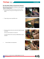
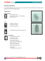
1
user manual
Table of Contents
Table of Contents
Section 1 Introduction.....................................................................................................................1-1
Warranty and Documentation...........................................................................................................1-1
Release Details....................................................................................................................................1-1
Trademarks and Patents.....................................................................................................................1-2
Section 2 Global Support................................................................................................................2-1
Manufacturing Facilities . ..................................................................................................................2-1
Regional Offices..................................................................................................................................2-1
International Representatives............................................................................................................2-2
Section 3 Safety................................................................................................................................3-1
Safety and Handling...........................................................................................................................3-1
Operating the Mold............................................................................................................................3-1
Notices.................................................................................................................................................3-1
Cautions...............................................................................................................................................3-2
Heater Element Caution.....................................................................................................................3-2
Section 4 Preparation.......................................................................................................................4-1
Screw Lengths....................................................................................................................................4-1
Tools Required....................................................................................................................................4-2
Unpacking...........................................................................................................................................4-3
Cleaning...............................................................................................................................................4-3
Establishing Your System Type..........................................................................................................4-3
Typical System Layout.......................................................................................................................4-4
HY8300 Hydraulic Actuator - Typical Components...........................................................................4-5
HY8300 Hydraulic Actuator - Typical Components...........................................................................4-6
PY8300 Pneumatic Actuator - Typical Components.........................................................................4-7
PY8300 Pneumatic Actuator - Typical Components.........................................................................4-8
Section 5 Assembly..........................................................................................................................5-1
Gate Seal Finishing.............................................................................................................................5-3
Thermocouple Installation.................................................................................................................5-4
Actuator Installation (Hydraulic)........................................................................................................5-7
Valve Pin Installation..........................................................................................................................5-9
Aluminum Channel Assembly......................................................................................................... 5-11
Section 6 Electrical Testing..............................................................................................................6-1
Wiring Check.......................................................................................................................................6-1
Ground Shorts Test.............................................................................................................................6-1
Thermocouple Continuity Test...........................................................................................................6-2
Pinch Point Test...................................................................................................................................6-2
Heater Continuity................................................................................................................................6-2
Updates are available online at www.moldmasters.com
© 2010 Mold-Masters (2007) Limited. All Rights Reserved.
Revised April 2010 v 2.0
i
Table of Contents
Section 7 System Installation.........................................................................................................7-1
Assembling the Fusion-Series Hot-Half............................................................................................7-1
Manifold Installation - Unpacking.....................................................................................................7-2
Mold Cavity Preparation ...................................................................................................................7-3
Section 8 System Start Up & Shut Down......................................................................................8-1
Section 9 Color Change...................................................................................................................9-1
Color Change for Hot Tip/Sprue System...........................................................................................9-1
Color Change for Valve Gate System................................................................................................9-2
Locating source of contamination.....................................................................................................9-1
Section 10 Troubleshooting..............................................................................................................10-1
Moisture Related Issues...................................................................................................................10-2
Resin Moisture Contamination........................................................................................................10-2
Resin Drying Issues..........................................................................................................................10-2
Importance of Pre-Drying Resin......................................................................................................10-2
Pre-Molding Precautions..................................................................................................................10-3
History...............................................................................................................................................10-3
Material..............................................................................................................................................10-3
Hardware...........................................................................................................................................10-3
Settings..............................................................................................................................................10-3
Establishing Root Cause..................................................................................................................10-4
Fault Identification............................................................................................................................10-4
Defect types, causes and remedies index......................................................................................10-5
Updates are available online at www.moldmasters.com
© 2010 Mold-Masters (2007) Limited. All Rights Reserved.
Revised April 2010 v 2.0
ii
Introduction
Section 1 Introduction
We would like to take this opportunity to thank you for purchasing a Mold-Masters Fusion G2® hot runner.
The purpose of this manual is to assist users in the integration, operation and maintenance of Mold-Masters
systems. This manual is designed to cover most system configurations. For additional information, please
contact your representative or a Mold-Masters office.
Please note that the responsibility for the safety of personnel remains exclusively with the employer. It is the
obligation of the employer to properly train and instruct its personnel in the safe operation of equipment including maintenance and the purpose and proper use of all the safety devices. In addition, the employer must
provide its personnel with all necessary protective clothing, including such items as a face shield and heat
resistant gloves. Any instructional material provided by Mold-Masters for the operation and maintenance of
equipment, does not in any way absolve the employer from fulfilling these obligations and Mold-Masters
disclaims liability for injury to personnel using equipment supplied.
Warranty and Documentation
Your original system documentation contains warranty details. If for any reason, parts must be returned to
Mold-Masters, it is essential to obtain prior pre-authorization and a return authorization number.
Documentation will include any or all of the following:
• Parts list containing all system components. Together with the general assembly drawing, the
parts list should be referenced when ordering spare parts.
• General assembly drawing used to integrate your hot runner system into mold.
• Hot half drawing used to integrate hot half to cavity plate.
When ordering this manual, please reference document number: MMFSUM.
Release Details
Document #
Release Date
Version
MMFSUM02
April 2010
02
This document has been reviewed by: Mold-Masters Application Engineering; Design Engineering; Sales and Marketing; Service.
This manual should be used in conjunction with any appropriate TempMaster Temperature
Controller User Manual.
Updates are available online at www.moldmasters.com
© 2010 Mold-Masters (2007) Limited. All Rights Reserved.
Revised April 2010 v 2.0
1-1
Introduction
Trademarks and Patents
ACCU-VALVE, DURA, FLEX-DURA FLEX-SERIES, FUSION-SERIES, HOT EDGE, INJECTIONEERING, MASTERPROBE, MASTER-SHOT, MOLD-MASTERS, MELT-DISK, MOLD-MASTERS ACADEMY, MASTER-SERIES,
MASTERSOLUTION, MASTERSPEED, MERLIN, MOLD-MASTERS SYSTEM, SCAN-MASTER, STACK-LINK,
are the registered trademarks of MOLD-MASTERS (2007) LIMITED.
Information contained herein is, to our best knowledge, true and accurate, but all recommendations or
suggestions are made without guarantee. Since the conditions of use are beyond our control, Mold-Masters disclaims any liability incurred in connection with the use of our products and information contained
herein. No person is authorized to make any statement or recommendation not contained herein, and any
such statement or recommendation so made shall not bind Mold-Masters. Furthermore, nothing contained herein shall be construed as a recommendation to use any product in conflict with existing patents
covering any products or its use, and no license implied or in fact granted herein under the claims of any
patents.
No part of this publication may be reproduced or transmitted in any form or by any means, electronic
or mechanical, including photocopy, recording, or any information storage and retrieval system without
permission in writing from the publisher. All details, standards and specifications may be altered in accordance with technical development without prior notification.
May be manufactured under one or more of the following U.S. Patents:
4941249, 4945630, 4981431, 5000675, 5002480, 5007821, 5015170, 5022846, 5028227, 5030084, 5046942,
5049062, 5061174, 5094603, 5106291, 5118279, 5118280, 5122050, 5125827, 5135377, 5142126, 5148594,
5206040, 5217730, 5223275, 5227596, 5227181, 5235737, 5238378, 5238391, 5268184, 5269676, 5282735,
5284436, 5299928, 5312242, 5326251, 5334008, 5334010, 5346388, 5366369, 5366370, 5387099, 5405258,
5421716, 5427519, 5429491, 5437093, 5441197, 5443381, 5460510, 5474440, 5494433, 5496168, 5507635,
5507636, 5536165, 5591465, 5599567, 5614233, 5641526, 5644835, 5652003, 5658604, 5695793, 5700499,
5704113, 5705202, 5707664, 5720995, 5792493, 5795599, 5820899, 5843361, 5849343, 5853777, 5935615,
5935616, 5935621, 5942257, 5952016, 5980236, 6009616, 6017209, 6030198, 6030202, 6062841, 6074191,
6077067, 6079972, 6095790, 6099780, 6113381, 6135751, 6162043, 6162044, 6176700, 6196826, 6203310,
6230384, 6270711, 6274075, 6286751, 6302680, 6318990, 6323465, 6348171, 6350401, 6394784, 6398537,
6405785, 6440350, 6454558, 6447283, 6488881, 6561789, 6575731, 6625873, 6638053, 6648622, 6655945,
6675055, 6688875, 6701997, 6739863, 6752618, 6755641, 6761557, 6769901, 6776600, 6780003, 6789745,
6830447, 6835060, 6840758, 6852265, 6860732, 6869276, 6884061, 6887418, 6890473, 6893249, 6921257,
6921259, 6936199, 6945767, 6945768, 6955534, 6962492, 6971869, 6988883, 6992269, 7014455, 7018197,
7022278, 7025585, 7025586, 7029269, 7040378, 7044191, 7044728, 7048532, 7086852, 7105123, 7108502,
7108503, 7115226, 7118703, 7118704, 7122145, 7125242, 7125243, 7128566, 7131832, 7131833, 7131834,
7134868, 7137806, 7137807, 7143496, 7156648, 7160100, 7160101, 7165965, 7168941, 7168943, 7172409,
7172411, 7175419, 7175420, 7179081, 7182591, 7182893, 7189071, 7192268, 7192270, 7198740, 7201335,
7210917, 7223092, 7238019, 724418, 7252498, 7255555, 7258536, 7270538, 7303720, 7306454, 7306455,
7314367, 7320588, 7320589, 7320590 7326049, 7344372, 7347684, 7364425, 7364426, 7370417,7377768,
7381050, 7396226, 7407379, 7407380, 7410353, 7410354, 7413432, 7416402, 7438551, 7462030, 7462031,
7462314, 7465165, 7470122, 7507081, 7510392, 7513771, 7513772, 7517214, 7524183, 7527490, 7544056,
7547208, 7553150, 7559760, 7559762, 7565221 D525592, RE38265, RE38396, RE38920, RE39935, RE40478,+
Pending.
© 2010 MOLD-MASTERS (2007) LIMITED. ALL RIGHTS RESERVED
Updates are available online at www.moldmasters.com
© 2010 Mold-Masters (2007) Limited. All Rights Reserved.
Revised April 2010 v 2.0
1-2
Global Support
Section 2 Global Support
Mold-Masters contacts worldwide
visit us online at www.moldmasters.com
Manufacturing Facilities
GLOBAL HEADQUARTER
CANADA
Mold-Masters Limited
233 Armstrong Avenue
Georgetown, Ontario
Canada L7G 4X5
tel: +1 (905) 877 0185
fax: +1 (905) 873 2818
[email protected]
EUROPEAN HEADQUARTER
GERMANY / SWITZERLAND
Mold-Masters Europa GmbH
Postfach/P.O. Box 19 01 45
76503 Baden-Baden, Germany
Neumattring 1
76532 Baden-Baden, Germany
tel: +49 7221 50990
fax: +49 7221 53093
[email protected]
ASIAN HEADQUARTER
CHINA/HONG KONG/TAIWAN
Mold-Masters (KunShan) Co, Ltd
Zhao Tian Rd
Lu Jia Town, KunShan City
Jiang Su Province
People’s Republic of China
tel: +86 512 86162882
fax: +86 512-86162883
[email protected]
SOUTH AMERICAN
HEADQUARTER
BRAZIL
Mold-Masters do Brasil Ltda.
Rua Hum, 1106 e 1126 Jd. Manchester - Nova Veneza
SumarÈ - São Paulo Brasil
CEP 13178-440
tel: +55 19 3922 4265
fax: +55 19 3922 4266
[email protected]
INDIA
Mold-Masters Technologies
Private Limited
# 247, Alagesan Road,
Shiv Building, Saibaba Colony.
Coimbatore T. N.
India 641 011
tel: +91 422 423 4888 - 20
fax: +91 422 423 4800
[email protected]
JAPAN
Mold-Masters K.K.
1-4-17 Kurikidai, Asaoku
Kawasaki, Kanagawa
Japan, 215-0032
tel: +81 44 986 2101
fax: +81 44 986 3145
[email protected]
UNITED KINGDOM
Mold-Masters UK
Netherwood Road
Rotherwas
Hereford
HR2 6JU
tel: +44 1432 265768
fax: +44 1432 263782
[email protected]
U.S.A.
Mold-Masters Injectioneering LLC
103 Peyerk Court
Romeo, MI 48065
tel: +1 800 450 2270 (USA)
tel: +1 (586) 752-6551
fax: +1 (586) 752 6552
[email protected]
Regional Offices
AUSTRIA / HUNGARY
Mold-Masters Handelsges.m.b.H.
Pyhrnstrasse 16
A-4553 Schlierbach
Austria
tel: +43 7582/51877
fax: +43 7582/51877 18
[email protected]
FRANCE
Mold-Masters France
ZI la Marinière,
2 Rue Bernard Palissy
91070 Bondoufle
tel: +33 1 82 05 00 80
fax: +33 1 82 05 00 83
[email protected]
KOREA
Mold-Masters Korea Ltd
708 Byucksan Digital Valley 5 Cha,
60-73 Gasan-dong, Geumcheon-gu,
Seoul,153-788,South Korea
Tel:+82 2 2082 4755
Fax:+82 2 2082 4756
[email protected]
Updates are available online at www.moldmasters.com
© 2010 Mold-Masters (2007) Limited. All Rights Reserved.
Revised April 2010 v 2.0
2-1
Global Support
Regional Offices - Con't
MEXICO
Mold-Masters Mexico
Av. Palmira 407
Villas Palmira,
Lomas del Marques
Queretaro, Qro. Mexico 76146
Tel: +52 442 2456378
[email protected]
SINGAPORE / MALAYSIA
INDONESIA / THAILAND
Mold-Masters Singapore PTE. Ltd.
No 48 Toh Guan Road East
#06-140 Enterprise Hub
Singapore 608586
Republic of Singapore
tel: +65 6261 7793
fax: +65 6261 8378
[email protected]
SPAIN
Mold-Masters España
Serennia Business Center
Buenos Aires 37-29
08902 Hospitalet de Llobregat
Barcelona, Spain
tel: +34 93 802 36 01
fax: +34 93 802 49 08
[email protected]
UNITED KINGDOM
Mold-Masters (UK) Limited
Unit 28, The Gateway
Birmingham Airport
Birmingham B26 3QD
United Kingdom
tel: +44 121 781 7800
fax: +44 121 782 4604
[email protected]
CZECH REPUBLIC
Mold-Masters Europa GmbH
Hlavni 823
75654 Zubri
Czech Republic
tel: +420 571 619 017
fax: +420 571 619 018
[email protected]
POLAND
Mold-Masters Europa GmbH
Skr. Pocztowa 59
00-908 Warszawa
Poland
tel: +48 (0) 66 91 80 888
fax: +48 (0) 66 91 80 208
[email protected]
International Representatives
Australia
Comtec I P E
1084 South Road,
Edwardstown, South Australia 5039
PO Box 338, Magill,
South Australia 5072
tel: +61 8 8374 4633
fax: +61 8 8299 0892
[email protected]
Bulgaria
Mold-Trade OOD
62, Aleksandrovska St.
Ruse City
Bulgaria
tel: +359 82 821 054
fax: +359 82 821 054
[email protected]
Denmark, Norway, Sweden
Englmayer A/S
Skenkelsoevej 9, Postbox 35
DK - 3650 Oelstykke, Denmark
tel: +45 46 733847
fax: +45 46 733859
[email protected]
Finland
Oy Scalar Ltd.
Mestarintie 5
SF-12100 Oitti, Finland
tel: +358 19 783 191
fax: +358 19 783 190
[email protected]
Israel
ASAF INDUSTRIES Ltd.
29 Habanai Street
PO Box 5598 Holon 58154
Israel
tel: +972 3 5581290
fax: +972 3 5581293
[email protected]
Italy
Commerciale Isola SPA
Via G.B. Tiepolo 3
35010 Cadoneghe, (Padova), Italy
tel: +39 49 706600
fax: +39 49 8874231
[email protected]
Portugal
Gecim LDA
Rua Fonte Dos Ingleses, No 2
Engenho
2430-130 Marinha Grande, Portugal
tel: +351 244 575600
fax: +351 244 575601
[email protected]
Romania
International Mold Trade Co. SRL
Str. Constantin Aricescu, Nr. 21
Bl. 20, Sc. 2, Apt. 20
Bucharest - Sector 1, Romania
tel: +4 021 230 60 51
fax : +4 021 231 78 43
[email protected]
Russia
OOO Portmold
Gefsimanskie prudy 4, office 2
141312 Russian Federation
Moscow region
Sergiev Posad
tel: 007 495 743 48 65
fax: 007 496 549 25 26
[email protected]
Turkey
MMG Consulting & Engineering
Yesil Çesme Sok No:30/3
Çiftehavuzlar 81060, Istanbul, Turkey
tel: +90 216 357 0783
fax: +90 216 385 0656
[email protected]
Vietnam
Lotus Chemical Technology
393 Dien Bien Phu St., Ward 4, Dist. 3,
HoChiMinh City, Vietnam
tel: +84 8 832 7605,
fax: +84 8 832 7730
[email protected]
Updates are available online at www.moldmasters.com
© 2010 Mold-Masters (2007) Limited. All Rights Reserved.
Revised April 2010 v 2.0
2-2
Safety
Section 3 Safety
High injection pressures and high temperatures are used in the operation of hot runners. To protect the
operator in the work place, ensure that all safety devices are installed on the machine.
• Be aware of all warning labels attached to the mold and machine.
• Refer to the machine user manual for safety procedures and checks not included here in the
hot runner specific manual.
Notices
To make the manual easier to use, we've included notices throughout that highlight important information.
See below.
SAFETY WARNING:
Safety warning indicates a potentially hazardous situation, which if not avoided, could
result in serious injury or death.
CAUTION:
Caution indicates that damage to equipment is possible if instruction is not followed.
IMPORTANT:
Important indicates useful additional information or is used as a reminder of important
information.
GENERAL SAFETY WARNINGS
The equipment supplied is subjected to high injection pressures and high temperatures.
Ensure that extreme caution is observed in the operation and maintenance of the hot runner
system and the injection molding machines.
• Do not operate the equipment with unconfined long hair, loose clothing or jewelry,
including name badges, neckties, etc. These may get caught by the moving belt
mechanism and can cause death or serious injury.
• Never disable or bypass a safety device.
• It is highly recommended that all operators wear face shields and use heat resistant
gloves when working around the feed throat, purging the machine or cleaning the gates
of the mold.
• Check frequently for possible oil leaks/water leaks. Stop the machine and make repairs.
• Remove purgings from the machine immediately.
• Never touch or inspect the timing belt when power is on and motor and controller are
connected. Unplug the controller before any maintenance.
• Always cover belt area with proper protecting sheet before any bench test or in-mold
testing.
• High Voltage and amperage cables are connected to the controller (220VAC). There is
also a high voltage cable connection between servo motor and controller.
• Unplug the controller before performing any maintenance work.
Updates are available online at www.moldmasters.com
© 2010 Mold-Masters (2007) Limited. All Rights Reserved.
Revised April 2010 v 2.0
3-1
Safety
GENERAL SAFETY WARNINGS - Con't
• Hoses fitted to the mold will contain high or low temperature fluids or air under high
pressure. The operator must shut down and lockout these systems as well as relieving
any pressure before performing any work with these hoses.
• Never perform any work on the mold unless the hydraulic pump has been stopped.
• High voltage and amperage cables are connected to the mold. Electric power must be
shut off prior to installing or removing any cables.
• Water and or hydraulics on the mold may be in close proximity to electrical connections
and equipment. Water leakage may cause an electrical short circuit. Hydraulic fluid
leakage may cause a fire hazard. Always keep water and /or hydraulic hoses and fittings
in good condition to avoid leaks.
Operating the Mold
Check that all coolant, hydraulic and air lines as well as electrical cables will not interfere
with the moving parts of the mold, machine or robot. The lines must be of sufficient length
so that they will not strain or pinch when the mold halves separate.
GENERAL CAUTIONS
• For water-cooled gate inserts, coolant must be maintained with the proper mixture to
prevent corrosion and circuit blockage.
• Care must be taken to ensure the nozzle terminal ends do not come in contact with the
hydraulic fluid. The nozzles may short out or become damaged.
• Do not mix electrical power cables with thermocouple extension cables. They are not
designed to carry the power load or list accurate temperature readings in each other’s
application.
Heater Element
To maximize heater element and component life, the temperature must be controlled and
maintained within safe operating limits. Mold-Masters strongly recommends individual
control of each heated component, including heater plates, with a reliable temperature controller that includes soft-start protection.
All Mold-Masters heated components are manufactured to standards that ensure safe and
reliable operation provided that the following precautions are met:
• Always operate the system using correctly installed “J” type thermocouples connected
to a reliable temperature controller with “soft-start” protection.
• Avoid running the system for long periods on “manual” control.
• Use caution when applying power in “manual” mode. Use minimum heat required for
the process to avoid overheating and possible damage to components.
• Always replace pinched or damaged thermocouples.
• When “grouping” heated components together and controlling more than one load
from a single thermocouple, make sure that the components are of similar material,
wattage, size and are exposed to the same thermal conditions.
• When replacing heater plates or other heated components always replace with genuine
• Mold-Masters components of the same type and install as originally specified on MoldMasters general assembly drawings.
Updates are available online at www.moldmasters.com
© 2010 Mold-Masters (2007) Limited. All Rights Reserved.
Revised April 2010 v 2.0
3-2
Preparation
Section 4 Preparation
Section 4 - Preparation
Introduction
The following section is a step-by-step guide to preparing your Mold-Masters® system for use.
Screw Lengths
WARNING:
The use of an incorrect size, length and grade screw could cause the screw to shear, fatigue
or stretch beyond its yield point, resulting in expensive downtime of the hot runner.
Be aware of warnings placed on the assembly drawings. When the manifold is heated the
metal expands stretching the mounting screws, if screw lengths are shortened there is a possibility of shearing.
The expansion factor is calculated into the length of each screw size.
WARNING
DO NOT SHORTEN SCREW
S.H.C.S. M10
(ISO-GRADE 12.90)
(ASTM A574)
NOT SUPPLIED BY
MOLD-MASTERS
E
L
P
M
A
X
E
Updates are available online at www.moldmasters.com
© 2010 Mold-Masters (2007) Limited. All Rights Reserved.
Revised April 2010 v 2.0
4-1
Preparation
Tools Required
Depending on the size and complexity of your hot runner system, you will require most of the tools and
materials listed below.
•
llen keys - Set of imperial size keys and metric sizes for use on both imperial and metric cap
A
screws (depending on system).
•
nti-seize compound - To prevent oxidation of screw threads that could cause screws to seize with
A
high temperatures.
•
Solvents (denatured alcohol) - For removal of rust inhibitors.
•
Calibrated torque wrench - For consistent screw pressure throughout the system.
•
Depth micrometer - To check bore depths.
•
Bluing Compound - For checking face contact.
•
Sockets.
•
Plastic face hammer.
Unpacking
1. Carefully remove the system from the shipping box and check that the system is received in good
condition and no damage occurred during shipment.
2. Check that all mold base dimensions are correct and correspond to Mold-Masters general assembly
drawings.
Cleaning
All nozzles, manifolds and hot runner components must be free of the rust inhibitor applied at the factory.
1. Remove protective covers from all gate seals.
2. Remove tape from inlet and clean.
Updates are available online at www.moldmasters.com
© 2010 Mold-Masters (2007) Limited. All Rights Reserved.
Revised April 2010 v 2.0
4-2
Preparation
Fusion G2 Hydraulic Cylinder Components
Hydraulic Cylinder Assembly
1. Install the rod seal - RODSEAL06 (Two Piece Design.
2. Press the seals into the housing.
Updates are available online at www.moldmasters.com
© 2010 Mold-Masters (2007) Limited. All Rights Reserved.
Revised April 2010 v 2.0
4-3
Preparation
3. Install the rod seal retainer clip - RGN130029.
4. Install the water circuit pipe plug - PP1/16-27
(Use pipe sealant on threads).
5. Install the piston seals - PS0003 (Three Piece
Design)
Updates are available online at www.moldmasters.com
© 2010 Mold-Masters (2007) Limited. All Rights Reserved.
Revised April 2010 v 2.0
4-4
Preparation
6. Install the valve pin.
7. Install the valve pin spacer - SPACER42.
8. Install the piston top - HHPL-6HP50N-S.
9. Torque the piston top.
Updates are available online at www.moldmasters.com
© 2010 Mold-Masters (2007) Limited. All Rights Reserved.
Revised April 2010 v 2.0
4-5
Preparation
10. Install the cylinder top seal - PNOR2-129.
11. Install the cylinder bleeder valve - NIPPLEM8X1.
12. Assemble the piston into the cylinder bottom.
13. Assemble cylinder top to the cylinder bottom.
14. Apply anti-seize to the SHCS's. Updates are available online at www.moldmasters.com
© 2010 Mold-Masters (2007) Limited. All Rights Reserved.
Revised April 2010 v 2.0
4-6
Preparation
15. Install the cylinder top SHCS's.
16. Assemble the cylinder to the manifold.
17. Apply anti-seize to the SHCS's.
18. Tighten and torque all SHCS's in a crossing
pattern.
Fusion G2 Pneumatic Cylinder Components - w/ Anti-Rotation
Updates are available online at www.moldmasters.com
© 2010 Mold-Masters (2007) Limited. All Rights Reserved.
Revised April 2010 v 2.0
4-7
Preparation
Pneumatic Cylinder Assembly
1. Install the rod seal - RODSEAL08 (Two Piece Design).
2. Install the piston, forming the seal into position.
3. Install the wiper seal - WS0002 (Two Piece Design).
4. Install the piston, forming the seal into position.
Updates are available online at www.moldmasters.com
© 2010 Mold-Masters (2007) Limited. All Rights Reserved.
Revised April 2010 v 2.0
4-8
Preparation
5. Install the piston seals - PS0012 (Two Piece
Design).
6. Install the piston top - HHPL-6HP50N-S.
7. Torque the piston top.
8. Assemble the piston into the cylinder bottom.
Updates are available online at www.moldmasters.com
© 2010 Mold-Masters (2007) Limited. All Rights Reserved.
Revised April 2010 v 2.0
4-9
Preparation
9. Install the cylinder top seal - PNOR2-038.
10. Assemble cylinder top to the cylinder bottom.
11. Apply anti-seize to the SHCS's.
12. Install the cylinder top SHCS's.
13. Install the Piston Collar to the Mounting Base.
Updates are available online at www.moldmasters.com
© 2010 Mold-Masters (2007) Limited. All Rights Reserved.
Revised April 2010 v 2.0
4-10
Preparation
14. Assemble the cylinder mounting base to the
manifold.
15. Apply anti-seize to the SHCS's.
16. Tighten all SHCS's in a crossing pattern.
17. Torque all SHCS's in a crossing pattern.
Updates are available online at www.moldmasters.com
© 2010 Mold-Masters (2007) Limited. All Rights Reserved.
Revised April 2010 v 2.0
4-11
Preparation
18. Assemble the cylinder to the mounting base.
19. Apply anti-seize to the SHCS's.
20. Tighten all SHCS's in a crossing pattern.
21. Torque all SHCS's in a crossing pattern.
Updates are available online at www.moldmasters.com
© 2010 Mold-Masters (2007) Limited. All Rights Reserved.
Revised April 2010 v 2.0
4-12
Assembly
Section 5 Assembly
Section 5 - Assembly
Introduction
This section is a step-by-step guide to assembling your Mold-Masters Fusion G2 hot runner system.
Gate Seal Finishing
Most nozzles are supplied with the gate seal installed (except when the seal requires final machining by a
toolmaker, such as the Hot Valve / Hot Sprue).
NOTE:
The gate seals supplied with your system may need to be adjusted to tolerances based on the material grade and cooling in the cavity. Refer to your Mold-Masters General Assembly Gate Detail
drawing to determine if gate seal finishing is required. Refer to the general assembly drawing to
determine which gating method applies.
Hot Valve / Hot Sprue / F Type
Hot valve and hot sprue gated systems are supplied with gate seals that are oversize in length. They must
be machined prior to installing the nozzle into the nozzle well bore.
NOTE:
Heat expansion of the nozzle must also
be taken into consideration.
Contour of gate seal should be done at
process temperature.
Check the chart on the general assembly drawings
for the length and contact height required.
See Contact Length "H" on table below.
CAUTION:
Ensure the thermocouple is not
damaged during machining
Figure 5-1 Hot Valve / Hot Sprue Gated System
Polymer Structure
Contact Length “H”
Amorphous Filled or Reinforced
4.00
Semi-crystalline Filled or Reinforced
3.00
Crystalline Filled or Reinforced
2.00
Updates are available online at www.moldmasters.com
© 2010 Mold-Masters (2007) Limited. All Rights Reserved.
Revised April 2010 v 2.0
5-1
Assembly
Pre-Assembly Checks of Gate Seals & Nozzle
Blue off the gate seal (and liner if relevant) to ensure a proper
contact on sealing surface:
*Note the following example shows gate seal with a liner).
1. Apply die blue to the gate seal and gate seal liner (if relevant).
2. Torque the gate seal to specified value.
3. Remove gate seal and verify transfer of die blue from gate
to the liner.
Verify transfer of die blue to nozzle core.
If not 100% blue on face contact your Mold Masters representative.
4.
Clean die blue from components.
Updates are available online at www.moldmasters.com
© 2010 Mold-Masters (2007) Limited. All Rights Reserved.
Revised April 2010 v 2.0
5-2
Assembly
Blue off nozzle core to manifold:
1. Inspect threads for burrs.
2. Apply die blue to nozzle core.
3. Apply anti-seize to threads.
4. Assemble nozzle to manifold and torque to specified value.
Updates are available online at www.moldmasters.com
© 2010 Mold-Masters (2007) Limited. All Rights Reserved.
Revised April 2010 v 2.0
5-3
Assembly
5. Verify transfer of die blue from nozzle core to manifold.
6. Clean die blue from components.
Assembly of Gate Seals to Nozzle
1. Apply anti-seize paste to all threaded interfaces.
2. Ensure all sealing surfaces are clean and dry.
Updates are available online at www.moldmasters.com
© 2010 Mold-Masters (2007) Limited. All Rights Reserved.
Revised April 2010 v 2.0
5-4
Assembly
3. Install gate seal and liner.
4. Torque to specified values.
Nozzle Assembly
Install nozzle heaters and sleeves
1. Install heaters and sleeves per specified drawings.
Install thermocouple.
1. Insert thermocouple into slot until bottoms out.
Updates are available online at www.moldmasters.com
© 2010 Mold-Masters (2007) Limited. All Rights Reserved.
Revised April 2010 v 2.0
5-5
Assembly
2. Bend thermocouple 180 degrees.
3. Install thermocouple retainer clip.
Install Heater Retaining Clip
1. Using snap ring pliers, expand the clip and install into
snap ring groove on nozzle core.
Updates are available online at www.moldmasters.com
© 2010 Mold-Masters (2007) Limited. All Rights Reserved.
Revised April 2010 v 2.0
5-6
Assembly
System Assembly
Assembly of Nozzle to Manifold
1. Follow pre-assembly checks mentioned earlier in the section.
2. Apply anti-seize to nozzle threads.
3. Assemble nozzle to manifold.
Torque nozzles to specified value.
Manifold Locator Installation
1. Apply anti-seize to socket head cap screws
(SHCS).
2. Install manifold locator to manifold and
torque SHCS to specified value.
Updates are available online at www.moldmasters.com
© 2010 Mold-Masters (2007) Limited. All Rights Reserved.
Revised April 2010 v 2.0
5-7
Assembly
3. Verify height of manifold locator to specified print dimension.
Install Support Bushings
1. Apply anti-seize to SHCS.
2. Install support bushing to manifold and torque SHCS to
specified value.
3. Repeat for other support bushings (typical application
will require 1 support bushing per nozzle).
Updates are available online at www.moldmasters.com
© 2010 Mold-Masters (2007) Limited. All Rights Reserved.
Revised April 2010 v 2.0
5-8
Assembly
4. Verify height of support bushing and manifold locator
to print specifications.
Install Manifold Thermocouple
1. Ensure thermocouple holes in manifold are clean and
free of blockage.
2. Install manifold thermocouple into manifold thermocouple hole until it bottoms out in the hole.
3. Bend thermocouples into slot.
Updates are available online at www.moldmasters.com
© 2010 Mold-Masters (2007) Limited. All Rights Reserved.
Revised April 2010 v 2.0
5-9
Assembly
4. Install manifold ground strap and thermocouple retention screw combination.
Install Inlet
1. Apply die blue to bottom of inlet.
2. Apply anti-seize to SHC screws and install inlet to manifold.
3. Torque screws in a crossing pattern gradually increasing torque to specified value.
Updates are available online at www.moldmasters.com
© 2010 Mold-Masters (2007) Limited. All Rights Reserved.
Revised April 2010 v 2.0
5-10
Assembly
4. Remove inlet to verify blued surfaces.
If not 100% blue on face, contact your Mold Masters
representative.
5. Clean the die blue from the inlet and manifold.
6. Re-install inlet. Torque screws in a crossing pattern
gradually increasing torque to specified value.
7. Blue the inlet seal and verify blued surfaces to check fit
of seal in the inlet.
Updates are available online at www.moldmasters.com
© 2010 Mold-Masters (2007) Limited. All Rights Reserved.
Revised April 2010 v 2.0
5-11
Assembly
8. Clean blue from inlet seal and inlet.
9. Install inlet heaters and sleeves per specified
drawing.
10. Apply anti-seize to threads and install inlet seal
to inlet.
11. Torque to specified value.
Updates are available online at www.moldmasters.com
© 2010 Mold-Masters (2007) Limited. All Rights Reserved.
Revised April 2010 v 2.0
5-12
Assembly
Install inlet thermocouple
1. Install thermocouple into slot until bottoms out.
2. Bend 180 degrees.
3. Install thermocouple clip.
Install valve bushing
1. Blue valve insert.
Updates are available online at www.moldmasters.com
© 2010 Mold-Masters (2007) Limited. All Rights Reserved.
Revised April 2010 v 2.0
5-13
Assembly
2. Install valve insert into valve nut.
3. Apply anti-seize to the SHCS's.
4. Install the SHCS's in a crossing pattern.
5. Remove valve bushing, and verify blue on all
surfaces.
6. Clean bluing from all components.
7. Install and torque in a crossing pattern.
8. Install valve pin to verify fit.
Updates are available online at www.moldmasters.com
© 2010 Mold-Masters (2007) Limited. All Rights Reserved.
Revised April 2010 v 2.0
5-14
Assembly
Install Cylinder to Manifold (Pneumatic)
1. Install pneumatic cylinder mounting plate to manifold.
2. Apply anti-seize paste to SHCS.
3. Torque screws in a crossing pattern gradually increasing torque to specified value.
4. Place cylinder housing onto cylinder mounting
plate.
Updates are available online at www.moldmasters.com
© 2010 Mold-Masters (2007) Limited. All Rights Reserved.
Revised April 2010 v 2.0
5-15
Assembly
5. Insert valve pin into piston.
6. Apply anti-seize paste to piston top.
7. Install piston top into piston.
8. Install piston into cylinder housing.
Updates are available online at www.moldmasters.com
© 2010 Mold-Masters (2007) Limited. All Rights Reserved.
Revised April 2010 v 2.0
5-16
Assembly
9.Install cylinder top o-ring.
10. Install cylinder top.
11. A
pply anti-seize paste to SHCS and torque screws
in a crossing pattern gradually increasing torque to
specified value.
Updates are available online at www.moldmasters.com
© 2010 Mold-Masters (2007) Limited. All Rights Reserved.
Revised April 2010 v 2.0
5-17
Assembly
Wiring
Attach Wire Armor to Side of Manifold
1. Apply anti-seize to button head cap screws (bhcs).
2. Install bhcs screws through appropriate slot in
wire armor.
3. Add spacer.
4. Install assembly to manifold.
Wiring
1. Group thermocouple and heater wires for a single
zone together and install high temp wire sheathing.
2. Label all heater and thermocouple zones.
Updates are available online at www.moldmasters.com
© 2010 Mold-Masters (2007) Limited. All Rights Reserved.
Revised April 2010 v 2.0
5-18
Assembly
3. Use heat resistant tape to tape/group thermocouple heater zones together to avoid losing labels.
4. Repeat for all zones.
Electrical Routing into Electrical Box
1. Install thermocouple and heater wires into electrical plugs per wiring schematic.
2. Install plugs into electrical box
Updates are available online at www.moldmasters.com
© 2010 Mold-Masters (2007) Limited. All Rights Reserved.
Revised April 2010 v 2.0
5-19
Assembly
Solenoid Valve Wiring
1. Install solenoid coil wires into electrical plugs per
wiring schematic.
2. Install plugs into electrical box.
Plumbing cylinders
1. Install hoses per drawing schematic.
Example of completed wired and plumbed 2-drop system
Updates are available online at www.moldmasters.com
© 2010 Mold-Masters (2007) Limited. All Rights Reserved.
Revised April 2010 v 2.0
5-20
Electrical Testing
Section 6 Electrical Testing
Introduction
This section contains electrical test procedures for your Mold-Masters hot runner system.
WARNING:
To avoid serious burns wear safety clothing consisting of a protective heat-resistant coat, heat-resistant gloves and a full face shield over safety glasses. Use adequate ventilation for fumes.
Contact with heated components may cause serious burns. Use a sign in a visible location indicating “Danger: Do Not Touch”.
Before performing any electrical work. Check that the hot runner is suitably grounded.
off the temperature controller and disconnect all electrical wires leading from the mold.
Failure to do so could result in a serious injury or death.
Wiring Check
1.
2.
3.
4.
5.
IMPORTANT:
Ensure that a qualified electrician performs all wiring.
Check that each wire and thermocouple has a zone number.
Check that wires are organized and taped together by zone and plug.
Check all wires are secured in wire channels..
Connect all power leads and thermocouple wires to mold plugs.
The electricity mains should only be connected to the injection mold when all electrical connections are
grounded and the mold is closed.
WARNING:
A disassembled nozzle should only be connected to an electrical supply when the nozzle has
been grounded or a safety isolating transformer is used.
Ground Shorts Test
1. Use an ohm meter to check for continuity between the Mold Power Connector ground pin (metal tabs on side) and the manifold steel. The ohm reading should be zero.
2. Measure the resistance between each pin of the Mold Power Connector (See Figure 6-1) and ground
(mold base). The reading should be ∞ (infinity). Occasionally, the electric heaters accumulate moisture,
which can reduce the resistance value to between 100 KΩ to 10 MΩ. The controller should be designed
to remove this moisture during start-up. Never apply full power to a heater if the insulation resistance
reading is below 300 KΩ. Heater resistance above 500 KΩ is acceptable. Also check this if the mold has
not been in use for a number of weeks/months.
3. If necessary, remove excess moisture before placing the heater under full current.
Updates are available online at www.moldmasters.com
© 2010 Mold-Masters (2007) Limited. All Rights Reserved.
Revised April 2010 v 2.0
6-1
Electrical Testing
Thermocouple Continuity Test
1. Measure the resistance between each pair of thermocouple
wires on the mold’s Thermocouple Connector. (See Figure
6-1). The resistance should be between 2.5 Ω and 25 Ω.
2. To verify alignment of thermocouple to heater, turn ON one
2
1
zone at a time & check that the temperature responds accordingly when the set temperature is adjusted.
Pinch Point Test
1. If there is a suspected pinch point on the thermocouple, remove the thermocouple from the hot runner.
2. Connect a controller to read the temperature.
3. Immerse the sheath of the thermocouple in boiling water at
the point that the thermocouple reads the temperature.
Figure 6-1 Mold Plug
1. Mold Power Connector
2. Thermocouple Connector
4. A good thermocouple will show a temperature rise as soon as
the tip of the thermocouple is immersed in water. If there is a
pinch point in the thermocouple there will be no change in the
reading until the pinch point on the thermocouple is immersed
in water.
Heater Continuity
Measure the resistance between each pair of heater power wires at the Mold Power Connector.
Compare your reading with your general assembly drawing.
Where:
R = resistance
V = voltage
P = power
R=
V²
P
Thermocouple Wiring Guidelines
• The thermocouples are type “J” grounded and are color coded to ASA standards. (White “+”/Red “- “).
• The tip must not be cut or crimped, and must touch the bottom of the bore in order to measure the correct temperature.
• Each heat source should have its own closed loop temperature control in order to achieve accurate
control.
• If there are not enough control zones, heat sources that have the same wattage and effect the same
environment, may be grouped together.
Heating Test with a Temperature Controller
• Never start the heating with more than 40% of power.
• Stay a minimum of 5 minutes at 212°F (100°C) before increasing heat.
• Stay with the system and monitor the initial heating to minimize risk.
Updates are available online at www.moldmasters.com
© 2010 Mold-Masters (2007) Limited. All Rights Reserved.
Revised April 2010 v 2.0
6-2
System Installation
Section 7 System Installation
Introduction
The following section is a step-by-step guide to install your Mold-Masters Fusion® G2 Series hot runner into
the existing Manifold Plate System or Spacer Block System.
Assembling the Fusion® G2 Series System
NOTE:
Refer to the general assembly drawings for instructions.
WARNING:
1.
Attach a crane that is rated to adequately support the weight of the cavity plate.
2.
Check that all wires are retained.
CAUTION:
CAUTION:
WARNING:
Make sure the lifting eyebolt, lifting chain and crane are rated to adequately support the
weight of the plate(s). Failure to do so can cause a serious injury.
Do not assemble/disassemble cavity plate with the valve pins forward.
Valve pins must be retracted prior to cavity plate installation.
Potential pinch point. Ensure that all wires are in the retainer groves.
Failure to do so can cause lost production due to hot runner down time.
Make sure the machine has been locked out and tagged out in accordance to the machines
documented procedures. Failure to do so may lead to serious injury or death.
Updates are available online at www.moldmasters.com
© 2010 Mold-Masters (2007) Limited. All Rights Reserved.
Revised April 2010 v 2.0
7-1
System Installation
Manifold Installation
Unpacking
1. Carefully open the shipping crate and inspect contents.
Secure loose items and check for any damage. Remove
any documentation or spares packages and set aside.
2. After removing all restraints, attach the sling to the hoist
and carefully remove the manifold assembly from the
shipping crate.
3. Verify all dimensions and tolerances and prepare manifold for insertion into the mold cavity.
4. Prepare mold cavity for Fusion G2 Series manifold
insertion. Mold type illustrated can be a Spacer Block
System or a Manifold Cavity System.
5. Clean all surfaces and dowel holes, ensuring that no de-
bris, burrs, shavings, dust, dirt, or other foreign material
which could interfere with measurements, exists. Ream
holes out if necessary.
Updates are available online at www.moldmasters.com
© 2010 Mold-Masters (2007) Limited. All Rights Reserved.
Revised April 2010 v 2.0
7-2
System Installation
Pre-Installation
1. Verify all dimensions, tolerances, angles, taps, chamfers, etc.
of the mold, against the engineering and general assembly
drawings.
Record values for future reference (right on the mold is suggested), using a Sharpie style marker.
2. Verify centres, depth tolerances, radii against general assembly drawings.
Install Manifold Locator Dowel
1. Using a depth micrometer, verify the dimensions of the
manifold locator pocket to those specified on print.
2. Apply anti-seize paste to SHCS.
3. Install manifold locator dowel.
Updates are available online at www.moldmasters.com
© 2010 Mold-Masters (2007) Limited. All Rights Reserved.
Revised April 2010 v 2.0
7-3
System Installation
System installation
1. Carefully install system into mold ensuring
manifold remains level to avoid damage to
nozzle wiring. Lower system and check system
is completed seated with tool.
2. Remove installation tool (lift bar, etc.).
3. Apply anti-seize to system screws and install
screws.
4. Torque system screws in a crossing pattern.
gradually increasing torque to specified value.
Updates are available online at www.moldmasters.com
© 2010 Mold-Masters (2007) Limited. All Rights Reserved.
Revised April 2010 v 2.0
7-4
System Installation
5. Install socket cap srews to secure electrical
and solenoid interface to exterior of mold
base.
6. Install clamp plate.
Updates are available online at www.moldmasters.com
© 2010 Mold-Masters (2007) Limited. All Rights Reserved.
Revised April 2010 v 2.0
7-5
System Start Up
Section 8 System Start Up & Shut
Introduction
This chapter explains how to start up and shut down your Fusion-Series hot runner system.
Pre-Start-up
1.
Install the mold into the molding machine.
NOTE:
Ensure the machine nozzle orifice matches or at most is 1.0 mm (0.040”) smaller than melt
entrance for the hot runner system.
2.
Connect all water lines and test. Water temperature is not to exceed 85° F. Water to Fusion
Valve Actuators must be turned on before heating is activated.
Connect all hydraulic / pneumatic lines (if applicable).
3.
NOTE:
CAUTION:
4.
Test the pin actuation (if applicable), only if the hot runner is at processing temperature.
5.
Connect all electrical components.
After the hot runner system is installed in the molding machine make sure to bleed all the air
out of the hydraulic lines. Possible high gate vestige could occur.
Check that the system is heated to processing temperature. Failure to do so could cause
damage to the valve pins. Water must be turned on for Fusion Actuation before turning on
temperature controls. Actuator water temperature cannot exceed 85° F.
Start-up
WARNING:
Assume the system is pressurized and hot at all times. Failure to do so can result in a serious
injury or death.
Updates are available online at www.moldmasters.com
© 2010 Mold-Masters (2007) Limited. All Rights Reserved.
Revised April 2010 v 2.0
8-1
System Start Up
NOTE:
1.
Turn ON the machine barrel and mold cooling system.
2.
Prior to start-up, ensure the:
•
•
•
When running thermally sensitive materials, use a thermally stable material as recommended by the material supplier for the initial start-up.
3.
Fusion Valve Gate Actuator water must be on. Maximum inlet water temperature not
to exceed 85° F.
Machine barrel is up to processing temperature.
Mold cooling is on and at cooling temperature.
Heat up the hot runner system to processing temperature.
Wait until ALL heating zones reach processing temperature before continuing.
WARNING:
4.
Start-up (only for empty hot runner system).
Extrude material through the hot runner system using 200 PSI (14 bar) of back pressure.
5.
Start-up (for systems filled with material).
Purge intended shot size twice from the barrel prior to bringing the machine barrel forward to
the hot runner interface.
Set injection time and pressure in coordination to part size, gate size and material.
6.
When the mold is open never inject material through hot runner system under high pressure.
Failure to do so can result in serious injury or death.
NOTE:
CAUTION:
For hot runner systems using heater plates, allow 20 minutes of soak time after the system
reaches processing temperature.
Failure to follow the above procedure may result in leakage/damage occurring in the hot
runner.
Shut Down
1.
Turn OFF all heat to the system.
2.Leave the mold cooling system ON, including valve actuator water, until the hot runner system temperature is within 100°F (37.7°C) of the mold temperature.
NOTE: Thermally sensitive materials should be purged from the hot runner system prior to shut
down using a thermally stable material with a similar processing temperature. For example,
a system running PVC should be initially started and subsequently shut down on LDPE.
Updates are available online at www.moldmasters.com
© 2010 Mold-Masters (2007) Limited. All Rights Reserved.
Revised April 2010 v 2.0
8-2
Color Change
Section 9 Color Change
Introduction
This chapter explains how to process your Fusion-Series hot runner system.
Color Change
In order to change from one color to another, it is necessary to remove all traces of the first color from the
injection molding system. Refer to the following procedures to assist in performing the color change.
Before commencing color change, review the following warnings.
WARNING:
WARNING:
WARNING:
To avoid serious burns when purging wear safety clothing consisting of a protective
heat-resistant coat, heat-resistant gloves and a full face shield over safety glasses.
Use adequate ventilation for fumes.
Do not look directly into the feed throat of a hopper. Unexpected release of resin may cause
serious burns. Use a mirror. Failure to do so may cause serious injury.
Never handle plastic purgings or drool until they have completely cooled. Purgings may appear solid but may still be hot and cause serious injury.
Color Change for a Hot Tip / Sprue System
1.
System is up & running with one color.
2.
Back off machine barrel, purge and introduce new color.
3.Increase hot runner system temperature on all zones 30° - 40° F above processing temperatures.
4.
Increase injection speed.
5.
Run 10 - 15 shots.
6.
Back off injection unit and switch off all heat on the hot runner. Leave Mold cooling on.
7.
Allow hot runner system to cool down. This pulls old material away from runner walls .
8.
Turn ON the hot runner system and heat to processing temperature.
9.
Bring machine barrel back in.
10.
Increase injection speed and (mold temperature) until color change is acceptable.
11.
Continue processing while resetting hot runner system temperatures and injection speed
Updates are available online at www.moldmasters.com
© 2010 Mold-Masters (2007) Limited. All Rights Reserved.
Revised April 2010 v 2.0
9-1
Color Change
WARNING:
Some plastics develop gases that may be dangerous to personal health. Follow the plastics
supplier’s recommendations. Review their material safety data sheet. Ensure the molding
area is well ventilated. Failure to do so can result in a serious injury or death.
Color Change for a Valve Gate System
1.
When the system is up and running with one color, back-off the injection unit, purge and
introduce the new color.
2.
Start molding the new color until the majority of old color has been removed from the
hot runner system.
Back-off the injection unit and switch off all heats on the hot runner system.
3.
CAUTION:
4.
Allow the hot runner system to cool down. Leave mold water cooling/actuator cooling on.
This pulls old material away from the runner walls
and allows new and old color to mix.
Heat up the system and start molding.
Do not activate the valve gate while purging or feeding the barrel, unless the hot runner system has reached normal processing temperature.
5.
Locating the Source of Contamination by a Previous Color
1.
Purge the original color from the machine, following the instructions in:
•
Color Change for a Hot Tip / Sprue System
•
Color Change for a Valve Gate System
2.
Load the hopper with a 2nd color (different from the intended color).
3.
Continue to purge until no trace of the 1st color appears.
4.
Shut off the hopper and continue to remove the 2nd color, following the instructions above.
5.
Load the hopper with the 3rd, and final intended color.
6.Purge the 3rd color through the injection unit to clean the injection unit of the 2nd color.
Continue to purge until no trace of the first color appears.
7.
If the 2nd color appears in the molded product then the problem is in the injection unit.
Updates are available online at www.moldmasters.com
© 2010 Mold-Masters (2007) Limited. All Rights Reserved.
Revised April 2010 v 2.0
9-2
Troubleshooting
Section 10 Troubleshooting
Introduction
This troubleshooting information assumes that the hot runner has been operational.
Basic rules for troubleshooting are:
•
Define the problem; what is seen is only a symptom of the underlying problem.
•
Develop a method to isolate the problem.
•
Test one item at a time to verify results.
•
onitor the final solution to verify that the problem has been solved. Repeat occurrences of
M
the same symptom may indicate other problems.
•
Document the solution so that a repeat occurrence can be solved quickly.
•
Consult other resources to augment the troubleshooting information in this manual.
One of the best resources may be your resin supplier.
NOTE:
WARNING:
Make sure the machine has been locked out and tagged out in accordance to the machines
documented procedures. Failure to do so may lead to serious injury or death.
Refer back to Section 3: Safety for proper procedures to be followed.
xtreme heat. Avoid contact with heated surfaces. To avoid serious burns wear safety clothE
ing consisting of a protective heat resistant coat and heat-resistant gloves. Use adequate
ventilation for fumes. Failure to do so can result in a serious injury.
Updates are available online at www.moldmasters.com
© 2010 Mold-Masters (2007) Limited. All Rights Reserved.
Revised April 2010 v 2.0
10-1
Troubleshooting
Moisture Related Issues
Many common molding issues can be directly attributed to moisture contamination of the production resin.
Generally, manufacturing resin is supplied from the manufacturer in ready to process pellets
that are in sealed, airtight containers. Follow manufacturers storage instructions, keeping containers sealed until ready to use.
Prior to using pellets, follow the drying instructions, as provided by the resin supplier and molding machine manufacturer (if applicable).
Resin Moisture Contamination
Moisture can be introduced into the resin in many ways:
•
during transportation
•
environmental exposure (aging)
•
malfunctioning heater/dryer
•
extreme humidity in atmosphere
•
inadequate or malfunctioning facility HVAC
Resin Drying Issues
During the drying stage of the resin (if applicable), ensure that:
•
the resin pellets are not overpacked
•
adequate air circulation is present
•
the drying system is properly sealed, according to manufacturers instructions
Importance of Pre-Drying Resin
Thermoplastic resins can be hygroscopic, able to absorb moisture from the air. Under normal processing
conditions, this can lead to degradation of the polymer during molding. Breakage of polymer chains
changes the properties, resulting in possible blisters, streaks, splay or other defects described in this section.
Recycled resins can have higher hygroscopic properties due to greater surface area and should be dried
separately from fresh resins.
If moisture issues are ruled out, continue with the troubleshooting tables in the following pages.
Updates are available online at www.moldmasters.com
© 2010 Mold-Masters (2007) Limited. All Rights Reserved.
Revised April 2010 v 2.0
10-2
Troubleshooting
Pre-Molding Precautions
Prior to commencing production, ensure that the following conditions have been met. This will
greatly reduce any future need to troubleshoot defective production.
History
•
eview any documentation associated with your batch job regarding the recipe using the
R
mold, molding machine, thermoplastic resin, environmental setting, etc.
•
eview comments, notes, logbooks, blogs, and anything other resource material that perR
tains to the batch job.
•
Verify that all settings such as all time, temperature, pressure, material, etc are correct.
Material
•
Ensure that the thermoplastic resin to be used is the right grade, and has been stored and/or
prepared/dried, etc, according to manufacturers specs.
•
Verify that the pigment/dye to be used meets manufacturers specifications, and is compatible
with the resin/molding machine/mold.
•
Verify the correct recycle ratio and adjust settings accordingly.
Hardware
•
ake sure the mold has been properly stored, and is dry, clean, free of rust, dirt, moisture,
M
residual resin, pigment and any protective coating.
•
heck that the temperature controller meets requirements, and is fully tested and operationC
al.
•
The
injection molding machine has been properly maintained, cleaned, lubricated; tolerances
and dimensions verified.
•
ake sure that the nozzles, cylinders, valves, gates, and any other variable that is appropriate
M
for the batch job has been chosen.
Settings
•
Ensure that all batch job parameters are correct:
•
•
•
•
Temperatures
Pressures
Injection Speed
Back Pressure
Updates are available online at www.moldmasters.com
© 2010 Mold-Masters (2007) Limited. All Rights Reserved.
Revised April 2010 v 2.0
10-3
Troubleshooting
Establishing Root Cause
This section is to be used as a reference tool only.
When a system that has been set up according to specification and was functioning normally suddenly
produces sub-standard parts, the data in the following pages may be used to determine the possible
cause, but only should be used as a guide.
A correct set up procedure that has been proven in will produce parts that meet design tolerances and
specifications. A sudden change in any parameter indicates a possible fault. Rather than modify other
settings to compensate for this variation, it is advisable to determine which of the original settings has
changed.
Fault Identification
The operator will need to evaluate all the possible conditions which may have caused the defect.
•
Identify the problem
•
Determine the frequency
•
Is the problem random or in the same location
•
Review past history logs for similar occurrences and resolutions.
Review the machine settings to ensure that there is no variation from the original set-up which was producing standard parts.
•
injection speed
•
melt heating
•
screw speed
•
locking
•
melt temperature
•
cushion
•
back pressure
•
mold heating
For a more thorough analysis of the defect, refer to the Troubleshooting Section in the following pages.
Updates are available online at www.moldmasters.com
© 2010 Mold-Masters (2007) Limited. All Rights Reserved.
Revised April 2010 v 2.0
10-4
Troubleshooting
Defect types, causes and remedies index
Parts have dark specks
Page 10-6
Parts have blisters and/or bubbles
Page 10-7
Parts have flow marks
Page 10-8
Parts have burn marks
Page 10-9
Parts are delaminating
Page 10-10
Parts have dimensional irregularities
Page 10-11
Parts are discolored Page 10-12
Parts contain flash Page 10-13
Parts surface has jetting
Page 10-14
Parts are pitted
Page 10-15
Page 10-16
Parts are sticking to cavity Page 10-17
Parts are sticking to core
Page 10-18
Parts are short
Page 10-19
Parts have sink marks or voids
Page 10-20
Parts display splay Page 10-21
Parts are streaked
Page 10-22
Parts are stringing
Page 10-23
Parts are warped
Parts surface is rough
Page 10-24
Parts have weld lines
Page 10-25
Updates are available online at www.moldmasters.com
© 2010 Mold-Masters (2007) Limited. All Rights Reserved.
Revised April 2010 v 2.0
10-5
Troubleshooting
Parts Have Dark Specks
The finished product contains dark particles.
(When transparent resins are usually used.)
Probable Cause:
Molding Machine
• Off line for extended period
• Barrel offline for extended period
• Barrel improperly purged
• Contamination in plasticizer
• Wrong nozzle
• Use of wrong screw
Mold
• Gate and/or runner has dead spots
Material
• Physical contamination of raw material
• Chemical contamination of raw material
• Particulate contamination from machine barrel
Solution (In sequence):
• Purge system with appropriate material
• Trace source of contamination and repair, remove or discard
• Adjust melt temperature if necessary
• Inspect for dead spots: gates; runners; nozzle; back flow valve
• Inspect feed screw for degradation
Updates are available online at www.moldmasters.com
© 2010 Mold-Masters (2007) Limited. All Rights Reserved.
Revised April 2010 v 2.0
10-6
Troubleshooting
Parts Have Blisters and/or Bubbles
The finished product contains small gas or air filled pockets or cooling voids.
Probable Cause:
Molding Machine
• Low Injection Pressure
• Back flow valve malfunctioning
• Suck-back cycle too long
• Rapid plasticizing
• Trapped air in feed
• Feed error
Mold
• Trapped or volatile gas
• Low mold temperature
• Poor thin/thick transition phase
• Inadequate venting
Material
• Overheating of resin
Solution: (In sequence)
• Verify control and/or holding pressure
• Increase back pressure
• Increase mold temperature
• Inspect back flow valve
• Ensure proper venting
• Increase gate size
• Decrease vent land length
Updates are available online at www.moldmasters.com
© 2010 Mold-Masters (2007) Limited. All Rights Reserved.
Revised April 2010 v 2.0
10-7
Troubleshooting
Parts Have Flow Marks
The finished product exhibits blush and flow marks, due to variations in material temperature from gradients between the machine nozzle and mold sprue bushing. Cold material in the nozzle tip section results in
a halo around the direct sprue.
Probable Cause:
Molding Machine
• Wrong injection speed
• Wrong injection pressure
• Hold pressure too long
Mold
• Insufficient mold cooling
• Temperature of mold too high around the gate
• Temperature of mold too cool
• Gate size is too small
• Gate is in wrong location
• Land length of gate is too long
• Incorrect hot runner system
Material
• Melt temperature is too low
Solution (In sequence):
• Adjust injection speed
• Add a large cold slug area
• Add cold wells at the end of the runner
system
• Use hot sprue bushing
• identify and eliminate dead pockets /sections
Updates are available online at www.moldmasters.com
© 2010 Mold-Masters (2007) Limited. All Rights Reserved.
Revised April 2010 v 2.0
10-8
Troubleshooting
Parts Have Burn Marks
The finished product display brown streaks. This is from the material being overheated due to trapped air (diesel
effect), which can lighten or darken the color.
Probable Cause:
Molding Machine
• High injection speed
• Backflow/check ring valve malfunctioning
• High back pressure
Mold
• Trapped or volatile gas
• Burning due to friction
• Incorrect sprue diameter
Material
• Overheated/underheated melt, possible shear
Solution: (In sequence)
• Clear blocked vent channels
• Lower injection speed
• Lower injection pressure
• Check heater functionality
• Check thermocouple functionality
• Reduce feed screw rotation
• Reduce melt temperature
• Increase mold cavity venting
• Enlarge gate
• Change gate position and/or size
Updates are available online at www.moldmasters.com
© 2010 Mold-Masters (2007) Limited. All Rights Reserved.
Revised April 2010 v 2.0
10-9
Troubleshooting
Parts are Delaminating
The finished product is separating into layers that can be peeled off; surface layers are flaking off.
Insufficient layer bonding as a result of high shear stresses; non-homogenious material.
Probable Cause:
Molding Machine
• High injection speed
Mold
• Cold mold
• Gate has sharp corners
• Sharp corners causing shear heat
Material
• Physical contamination of raw material
• Chemical contamination of raw material
• Melt too hot; poor melt
• Incompatible color dye
• High percentage of recycled material
Solution (In sequence):
• Melt temperature increased
• Mold temperature increased
• Injection speed decreased
• Contamination eliminated
• Regrind ratio adjusted
• Resin moisture content adjusted/changed
• System purged
• Sharp corners at gate reduced
Updates are available online at www.moldmasters.com
© 2010 Mold-Masters (2007) Limited. All Rights Reserved.
Revised April 2010 v 2.0
10-10
Troubleshooting
Parts Have Dimensional Irregularities
The finished product is of a different dimensional value than originally designed, or previous production.
Probable Cause:
Molding Machine
• Low injection pressure
• Short hold pressure time
• Damaged back-flow/check ring valve
• Short cycle time
• Cylinder clearance too big
• Nozzle heaters malfunctioning
Mold
• Temperature setting too high
• Small gate size resulting in wrong pressure
• Incorrect gate location
• Incorrect mold configuration/size
Material
• Generally not a material related issue unless excessive regrind is used.
Solution: (In sequence)
• Increase the injection pressure
• Increase the cooling time
• Increase the mold temperature
• Ensure cycle time is consistent
• Monitor molding machine for irregularities
• Balance regrind ratio
• Increase gate size
• Decrease gate land length
• Balance the runner and/or gate system
• Decrease cavity quantity
Updates are available online at www.moldmasters.com
© 2010 Mold-Masters (2007) Limited. All Rights Reserved.
Revised April 2010 v 2.0
10-11
Troubleshooting
Parts are Discolored
The finished product varies in color on different surfaces.
Probable Cause:
Molding Machine
• Contamination
Mold
• Incorrect sprue diameter
• Inadequate venting
Material
• Physical contamination of raw material
• Chemical contamination of raw material
• Melt too hot; poor melt
• Incompatible color dye
• Residence time too high
Solution (In sequence):
• Heating cylinder purged
• Resin temperature lowered by:
a. reducing cylinder temperature.
b. reducing screw speed
c. reducing back pressure
• Nozzle temperature decreased
• Residence time adjusted
• Regrind ratio adjusted
• Cycle time adjusted
• Check for external contamination sources
• Ensure proper cooling in all areas.
• Increase mold venting
Updates are available online at www.moldmasters.com
© 2010 Mold-Masters (2007) Limited. All Rights Reserved.
Revised April 2010 v 2.0
10-12
Troubleshooting
Parts contain Flash
Also known as "Fins" or "Spew"
The finished product contains a thin film of material attached at the mold parting line.
Probable Cause:
Molding Machine
• Low clamping pressure
• High injection pressure
• High injection speed
Mold
• Inadequate mold supports
• Low clamping force
• Damaged mold
• Projected area too large for machine capacity
Material
• Low melt viscosity
• High melt temperature
Solution: (In sequence)
• Reduce the injection speed
• Reduce the injection pressure
• Reduce the injection time
• Increase clamping force
• Inspect the mold for irregularities
• Reduce the melt temperature
• Inspect vent depth
• Switch to higher tonnage clamping machine
• Establish correct transfer position
• Reduce hold pressure
Updates are available online at www.moldmasters.com
© 2010 Mold-Masters (2007) Limited. All Rights Reserved.
Revised April 2010 v 2.0
10-13
Troubleshooting
Parts surface has Jetting
The finished product exhibits serpentine flow patterns on the surface as a result of the melt cooling prior to
complete filling of the mold.
Probable Cause:
Molding Machine
• High injection speed
Mold
• Cold mold
• Small gate
• Wrong gate land length
• Wrong gate location
Material
• Cold melt
Solution (In sequence):
• Decrease injection speed
• Verify nozzle temperature
• Increase mold temperature
• Increase melt temperature
• Increase gate size
• Modify gate location
Updates are available online at www.moldmasters.com
© 2010 Mold-Masters (2007) Limited. All Rights Reserved.
Revised April 2010 v 2.0
10-14
Troubleshooting
Parts are Pitted
The finished product contains unmelted particles or small holes on the surface.
Probable Cause:
Molding Machine
• Improper or worn out feed screw
• Low melt temperature
• Low injection speed
Mold
• Gating shear
• Sharp corners
Material
• Resin used is not homogeneous
• External contamination
Solution: (In sequence)
• Reduce shear
• Reduce back pressure
• Reduce injection speed
• Modify temperature
• Modify regrind ratio
• Modify shot size
• Inspect hot runner and nozzles
Updates are available online at www.moldmasters.com
© 2010 Mold-Masters (2007) Limited. All Rights Reserved.
Revised April 2010 v 2.0
10-15
Troubleshooting
Parts surface is Rough
The finished product exhibits patterns on the surface similar to grooves on a record, due to rapid cooling
of the melt as it nears mold surface, followed over and over again by fresh melt.
Probable Cause:
Molding Machine
• Low injection speed
• Low injection pressure
Mold
• Cold mold
• Irregularities in mold surface; defective polishing
Material
• Cold melt
Solution (In sequence):
• Increase injection speed
• Increase injection pressure
• Increase melt temperature
• Increase mold temperature
• Inspect mold surface
Updates are available online at www.moldmasters.com
© 2010 Mold-Masters (2007) Limited. All Rights Reserved.
Revised April 2010 v 2.0
10-16
Troubleshooting
Parts are sticking to cavity
The finished product does not properly release from the mold (female side).
Probable Cause:
Molding Machine
• High injection pressure
• High injection speed
• Long holding time
• High material feed
Mold
• Hot cavity
• Cold mold
• Defective mold surface
Material
• Melt too hot
Solution: (In sequence)
• Confirm cycle time for cooling
• Reduce injection pressure
• Reduce injection hold time
• Reduce injection speed
• Reduce injection time
• Adjust feed
• Inspect mold finish
• Increase mold opening cycle
• Lower mold temperature
• Adjust differential temperatures
• Inspect for appropriate mold release
Updates are available online at www.moldmasters.com
© 2010 Mold-Masters (2007) Limited. All Rights Reserved.
Revised April 2010 v 2.0
10-17
Troubleshooting
Parts are sticking to core
The finished product does not properly release from the mold (male side).
Probable Cause:
Molding Machine
• High injection pressure
Mold
• Hot core
• Bending of core
• Presence of vacuum
Material
• Generally not a material related issue
Solution (In sequence):
• Confirm cycle time for cooling
• Reduce injection pressure
• Reduce injection hold time
• Reduce injection time
• Adjust feed
• Reduce mold closed time
• Increase core temperature
• Decrease nozzle temperature
• Inspect mold for undercuts and/or improper draft
• Verify mold bending ratio
Updates are available online at www.moldmasters.com
© 2010 Mold-Masters (2007) Limited. All Rights Reserved.
Revised April 2010 v 2.0
10-18
Troubleshooting
Parts are short
The finished product is not completely formed.
Probable Cause:
Molding Machine
• Bad feed
• Low injection pressure
• Low injection speed
• Short injection time
• Back flow valve / check ring faulty
• Improper venting
Mold
• Insufficient venting
• Cold mold
Material
• Low melt temperature
• Viscous material
Solution (In sequence):
• Increase feed
• Increase injection pressure
• Increase feed temperature by increasing cylinder temperature
• Increase injection time
• Increase mold temperature
• Increase nozzle diameter
• Inspect for restrictions
• Increase gate size of sprue and runner system
Updates are available online at www.moldmasters.com
© 2010 Mold-Masters (2007) Limited. All Rights Reserved.
Revised April 2010 v 2.0
10-19
Troubleshooting
Parts have sinks or voids
The finished product has hollows and pockets in areas that do not cool sufficiently, causing contraction.
Probable Cause:
Molding Machine
• Low injection pressure
• Short injection time
• Insufficient material in cavity
• High injection speed
• Low back pressure
• Damaged backflow valve / check ring
Mold
• Mold not at required temperature
• Small gate leading to early freezing
• Gate land length too long
• Incorrect rib/wall dimensions
• Material flow incorrect
• Thick wall part
Material
• Hot material
• Material wrong grade for application
Solution: (In sequence)
• Adjust injection speed
• Increase injection hold time
• Increase injection pressure
• Adjust melt temperature
• Adjust mold temperature
• Inspect for hot spots
• Enlarge and/or add vents to mold parting line
• Increase sprue or runner size
• Increase gate size/reduce gate land length
• Relocate gate closer to heavy/thicker areas
• If possible, core out heavy wall sections
Updates are available online at www.moldmasters.com
© 2010 Mold-Masters (2007) Limited. All Rights Reserved.
Revised April 2010 v 2.0
10-20
Troubleshooting
Parts display splay
The finished product display splay/splash marks and/or silver streaks.
Probable Cause:
Molding Machine
• Resin degraded from overheating
• Cylinder contains hot spots
• Material trapped at nozzle tip
• Wrong injection pressure
• Wrong injection speed
• Low back pressure
Mold
• Friction related burning in gate, nozzle or hot runner
• Trapped volatile compounds
Material
• Hot melt
• Contaminated resin (moisture, dirt, organics)
• Degraded resin
Solution (In sequence):
• Dry resin according to procedure; check drying equipment for functionality
• Reduce nozzle temperature
• Reduce material temperature:
1. lower cylinder temperature; 2. reduce screw speed; 3. reduce back pressure
• Decrease injection speed
• Increase mold temperature
• Decrease or eliminate screw decompression
• Reduce cycle time
• Check for drooling
• Check for contamination in mold cavity
• Open gates
• Try mold in smaller shot-size press
Updates are available online at www.moldmasters.com
© 2010 Mold-Masters (2007) Limited. All Rights Reserved.
Revised April 2010 v 2.0
10-21
Troubleshooting
Parts are streaked
The finished product has large, dull and laminate appearance areas on the surface.
Probable Cause:
Molding Machine
• Back flow valve ring damaged
Mold
• Hot spots
• Material trapped in certain areas
Material
• Contamination of resin or machine
• If pattern is identical, cause may be the machine
• If pattern is erratic, cause may be the material or coloring
• Degraded or unstable material
Solution: (In sequence)
• Check for contamination
• Check barrel purging
• Inspect back flow ring for wear or cracks
• Inspect feed screw for wear and tear
• Inspect screw/barrel for tolerances
• Verify heater operation
• Verify thermocouple operation
Updates are available online at www.moldmasters.com
© 2010 Mold-Masters (2007) Limited. All Rights Reserved.
Revised April 2010 v 2.0
10-22
Troubleshooting
Parts are stringing
The finished product have thin plastic strings attached to the sprue.
Probable Cause:
Molding Machine
• High back pressure
• High nozzle temperature
Mold
• Incorrect sprue
Material
• Melt strength inadequate
Solution (In sequence):
• Reduce back pressure
• Modify nozzle temperature
• Modify temperature profile
• Eliminate sprue breaks
• Increase cooling time
• Decrease mold temperature at the gate
Updates are available online at www.moldmasters.com
© 2010 Mold-Masters (2007) Limited. All Rights Reserved.
Revised April 2010 v 2.0
10-23
Troubleshooting
Parts are warped
The finished product has pressure differences/stress on its surface, causing the part to be disfigured.
Probable Cause:
Molding Machine
• Wrong cooling time
• High injection pressure
Mold
• Gate located in wrong area
• Undercuts too big
• Cavity too hot
• Part is wrong design or too heavy
Material
• Fillers have wrong orientation
• Incorrect material
Solution (In sequence):
• Ensure temperature in both mold halves is equal
• Monitor part ejection from mold for uniformity
• Monitor part handling following ejection
• Verify part weight following ejection
• Increase injection hold time
• Increase cooling time
• Adjust injection pressure
• Adjust mold temperature; set sequential temperatures based on part geometry
• Check gate dimensions, quantities and locations
• Re-design part if necessary
Updates are available online at www.moldmasters.com
© 2010 Mold-Masters (2007) Limited. All Rights Reserved.
Revised April 2010 v 2.0
10-24
Troubleshooting
Parts have weld lines
The finished product has lines where two flow fronts meet and have not fused, creating the possibility of weak
areas and stress fractures.
Probable Cause:
Molding Machine
• Low injection speed
• Low injection pressure
• Short injection time forward
Mold
• Low mold temperature
• Poor venting
• Back flow valve / check ring malfunctioning
• Gates too far apart
• Redesign part
Material
• Cold melt
• Material wrong grade for application
Solution: (In sequence)
• Increase injection pressure
• Increase injection holding time
• Increase injection speed
• Increase cylinder temperature
• Increase mold temperature
• Check for venting
• Provide an overflow well adjacent to the weld area
• Modify the gate location
• Decrease gate land length
Updates are available online at www.moldmasters.com
© 2010 Mold-Masters (2007) Limited. All Rights Reserved.
Revised April 2010 v 2.0
10-25
NOTE TO MOLD MAKER:
This detailed user manual has been prepared to assist in the integration, processing
and troubleshooting of your Mold-Masters® System.
When this hot runner system has been integrated into the mold, please ensure that
this user manual is forwarded to the molder / end user together with the mold.
www.moldmasters.com
®
Mold-Masters and the Mold-Masters logo are registered trademarks of
Mold-Masters (2007) Limited. © 2010. MMFSUM01.