1
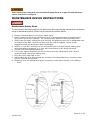
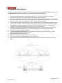
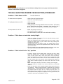
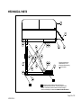
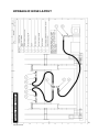
Loading Dock User’s Manual
Installation, Operations,
Maintenance and Parts
Serial No.:
Shipping Date:
Capacity:
Model No.
Power Pack:
Motor Voltage:
Controls:
Special Notes:
Do not install, operate or service this product unless you have
Read and understand the Safety Practices, Warnings, and Installation and
Operating Instructions contained in this User’s manual.
Failure to do so could result in death or serious injury.
50021004-2
1 OF 22
Table of Contents
Loading Dock User’s Manual ......................................................................................... 1
Table of Contents ....................................................................................................... 2
SAFETY ALERTS (Required reading!) ........................................................................... 3
SAFETY PRACTICES ..................................................................................................... 4
RESPONSIBILITIES OF OWNERS/USERS ........................................................................ 5
Deflection ............................................................................................................... 5
Inspection and Maintenance ...................................................................................... 5
Removal from Service .............................................................................................. 5
Repairs ................................................................................................................... 5
Operators ............................................................................................................... 5
Modifications or Alterations ....................................................................................... 5
INSTALLATION INSTRUCTIONS..................................................................................... 6
MAINTENANCE CHECK LIST - To be made by authorized personnel ................................... 6
SAFETY LABEL LOCATION ............................................................................................ 7
LABEL ITEM NUMBERS: ............................................................................................... 8
SAFETY LABELS .......................................................................................................... 9
OPERATIONS............................................................................................................. 10
Introduction ........................................................................................................... 10
Loading ................................................................................................................. 10
Operation .............................................................................................................. 10
MAINTENANCE DEVICE INSTRUCTIONS ........................................................................ 11
Maintenance Safety Strut ......................................................................................... 11
Mechanical Scissor Blocks ........................................................................................ 12
Adjustment Procedure for Limit Switch (if applicable) .................................................. 13
TROUBLE SHOOTING POWER PACK ELECTRIC/HYDRAULIC .............................................. 14
TROUBLE SHOOTING POWER PACK AIR/HYDRAULIC ...................................................... 15
HYDRAULIC CYLINDER OVERHAUL ............................................................................... 16
Procedure For Removal Of Cylinder(S) ....................................................................... 16
Installation Of New Or Repaired Cylinder(S) ............................................................... 16
PREVENTIVE MAINTENANCE ........................................................................................ 17
MECHANICAL PARTS .................................................................................................. 18
PARTS #................................................................................................................... 19
HYDRAULIC HOSE LAYOUT.......................................................................................... 20
MANUAL LOWERING VALVE......................................................................................... 21
LIMITED WARRANTY................................................................................................... 22
14021004-0
Page 2 of 22
SAFETY ALERTS
(Required reading!)
The following SAFETY ALERTS are intended to create awareness of owners,
operators and maintenance personnel of the potential safety hazards and the
steps that must be taken to avoid accidents. These same alerts are inserted
throughout this manual to identify specific hazards that may endanger
uninformed personnel. Identification of every conceivable hazardous situation
is impossible. Therefore, all personnel have the responsibility to diligently
exercise safe practices whenever exposed to this equipment.
This is a safety alert symbol. It is used to alert you to potential personal
injury hazards. Obey all safety messages that follow this symbol to avoid
possible injury or death.
Indicates imminently hazardous situation which, if not avoided will result in
death or serious injury.
Indicates a potentially hazardous situation which, if not avoided, could result
in death or serious injury.
Indicates a potentially hazardous situation which, if not avoided, may result in
minor or moderate injury.
Indicates a potentially hazardous situation which, may result in property
damage.
14021004-0
Page 3 of 22
SAFETY PRACTICES
Never go under the loading dock unless the maintenance device is engaged in accordance with the
manufacturer’s instructions. If maintenance or service is required: Only authorized service
personnel shall provide maintenance/service on the loading dock. Follow approved lock out
procedures. Do not work on or under the lift without properly engaging the lift’s maintenance
device, see Maintenance Device Instructions on page 11. The loading dock shall not be modified or
altered without the written permission of the original manufacturer.
Read these Safety Practices before installing, operating or servicing the loading dock. Failure to
follow the safety practices could result in death or serious injury.
Do not operate this loading dock unless you have training and authorization.
Read, understand and follow these instructions, the hazard labels on the loading dock, and other
warnings/instructions contained in this User’s Manual.
Prior to using the loading dock: verify that the safety devices supplied with the loading dock (guard
rail, restraint chains, toe guards, and warning bells, if so equipped), are in place and functioning
properly. Operate the loading dock through one complete lift/lower cycle and verify its proper
operation. At the same time inspect loading dock for any visible or obvious damage. If there is any
damage, or unusual vibration or noise, remove the lift from service using approved lockout
procedures. Notify maintenance personnel immediately.
Do not exceed the lift’s capacity as stated on the nameplate and center loads on the lift. Be aware
that the lift may have reduced capacity when loads are rolled over the platform‘s sides and ends.
If load is mobile, secure load in a fixed position before operating lift.
Prior to operating the lift, ensure that all personnel on or near the lift are aware of its imminent
operation, and that no person will be in harms ways during the use of the lift.
Ensure that objects are clear of the area beneath the platform, and immediately surrounding the
perimeter of the lift, while it is in use.
Keep area around lift free of oil, objects and debris that could cause slipping or tumbling into or
under the lift.
Hinged bridge (lip) must overlap truck bed a minimum of 4” (100 mm) before use. Do not use bridge
if it is supported solely by its lifting chains.
Verify that snap chains in all openings are securely in place during and after each use of the scissor
lift. Safety chain hooks are used to securely hold the hinged loading lips in their over center raised
position between use. Always return the hinged lips to the storage position secured with safety
chain hooks after each use.
14021004-0
Page 4 of 22
RESPONSIBILITIES OF OWNERS/USERS
Deflection
It is the responsibility of the user/purchaser to advice the manufacture where deflection may
be critical to the application.
Inspection and Maintenance
The lift shall be inspected and maintained in proper working order in accordance with the
manufacturer’s operating / maintenance manual and safe operating practices.
Only trained personnel and authorized personnel shall be permitted to perform maintenance /
service operations on the lift.
Maintenance / Service personnel shall have:
Read and/or have explained and understood the manufacturer’s operating
/maintenance manual, and all safety rules and labels, prior to performing any
maintenance/service operations on the equipment.
Full time unlimited access to the manufacturer’s operating/maintenance manual.
Removal from Service
Any lift not in safe operating condition such as, but not limited to excessive leakage, missing
rollers, pins or fasteners, any bent or cracked structural members, cut or frayed electric,
hydraulic or air lines, damaged or malfunctioning controls or safety devices, etc. shall be
removed from service until it is repaired to the original manufacturer’s standards.
Repairs
All repairs shall be made by qualified personnel in conformance with the manufacturer’s instructions.
Operators
Only trained personnel and authorized personnel shall be permitted to operate the lift.
Before Operation
Before using the lift, the operator shall have:
Read and or have explained, and understood, the manufacturer’s operating instructions
and safety rules
Inspect the lift for proper operation and condition. Any suspect item shall be carefully
examined and a determination made by a qualified person as to whether it constitutes a
hazard. All items not in conformance with the manufacturer’s specification shall be corrected
before further use of the lift.
During Operation
The lift shall only be used in accordance with the manufacturer’s operating/maintenance manual
Do not overload the lift.
Ensure that all safety devices are operational and in place.
Modifications or Alterations
Modifications or alterations of industrial loading docks shall be made only with written
permission of the original manufacturer. These changes shall be in conformance with all
applicable provisions of the standard and shall be as safe as the equipment was before
modification. These changes shall also satisfy all safety recommendations of the original
equipment manufacturer for the particular application of the lift
14021004-0
Page 5 of 22
To avoid injury stand clear of scissor mechanism/pinch point while in motion.
Do not work under lift without maintenance strut in place. See Maintenance DeviceInstructions
High voltage to be handled by authorized personnel only.
Stay clear of pinch points.
Before installing the loading dock read and follow the Safety Practices, on page number 4.
Stay clear of moving platform.
Loading dock must be anchored to floor.
INSTALLATION INSTRUCTIONS
Electrical power requirements are to be handled by a certified Electrician to ensure correct hook-up,
motor rotation and that all electrical circuitry is working properly.
1. Do not install the lift in a pit unless it has a bevel toe guard or other approved toe protection. A
shear point can exist which can cause severe injury to the foot.
2. Lift platforms traveling below floor levels may create openings, and the shape of the load and
how the load is arranged on the lift may create a toe hazard as the load passes the top edge of the
pit. Both situations may require guarding in accordance with Federal Regulations. Any such
guarding must be installed prior to operating the lift.
3. Before unstrapping the lift, place it in the desired location.
4. Unstrap the lift.
5. Take the controls and place them where desired.
6. Secure the loading dock to the floor with anchor bolts thru four (4) holes located at points as
marked. If shimming is required under the base frame hinge areas insure it extends the full area. If
shimming is required under the area of roller travel, the shim must extend over the full length of
travel to avoid bending of the base frame. Shims not included with equipment.
7. Before using the Elevating Dock/Lift Table, all of the Lifting Lugs or Clamping Closures must be
removed.
The unit is now ready for normal use. Observe all warning and precautions in this manual and on
the loading dock stickers.
MAINTENANCE CHECK LIST -
To be made by authorized personnel
Do not work under lift without maintenance strut/blocks in place.
Check all hoses and fittings at the base for signs of leaks.
Check the anchor bolts to make sure that they are tight, secure and not damaged.
See the maintenance section for cam follower lubrication.
Check electrical cords and wiring for any fraying or cuts.
Check electrical switches and controls for damaged or broken fittings.
14021004-0
Page 6 of 22
SAFETY LABEL LOCATION
SIDE VIEW
FRONT AND REAR VIEW
5
9
3
3
6
10
4/SIDE
2
6
1
6
4
4
11A
11B
11A
11B
11B
12
12
11A
12
Panel Box
NOTE:
14021004-0
It is the owner’s responsibility to ensure that all safety
labels are affixed in their original position, and remain
legible throughout the life of the loading dock
Page 7 of 22
LABEL ITEM NUMBERS:
ITEM
Q-TY
1
2
2
1
3
8
4
5
6
7
8
9
10
11
12
DESCRIPTION
Maximum rated Capacity Label
Intended to warn personnel to read operating
instructions before operating loading dock and the
maximum weight capacity with an evenly distributed
load, side and end axle loads.
Label/Serial Number Plate
Safety Stripping Label
Intended to caution personnel the loading dock may
be in operation and to stand clear
6
Scissor Leg Safety & Avoid Bodily Injury Label
Intended to warn personnel to read operating
instructions before using the loading dock, to warn of
possible bodily injury hazard
1
Stand Clear While in Motion Label
Intended to warn personnel to stand clear while the
loading dock is in operation
8
Pinch Point Label
Intended to warn personnel of pinch point hazard
causing bodily injury
1
High Voltage Label
Intended to warn personnel of high voltage hazard
1
Arc Flash & Shock Label
Intended to warn personnel of both electrical shock
and arc flash hazards
4
Do Not Operate Without Rails Label
Intended to warn personnel against using loading
dock without the guard rails and chains being in place
that were supplied with the lift
1
Bolted Close for Shipping Label
Intended to notify installer the loading dock is bolted
down for shipping and to avoid damaging the table
bolts must be removed before operating
Maintenance Device
11A-2 Intended to warn personnel not to use before reading
instructions in manual for proper usage
11B-3 Strut displayed as 11A, Block used for 3 sided pit 11B
Not to support lift when loaded
3
Do Not Work Under Lift
Intended to warn personnel to have the maintenance
device in place before going under lift
14021004-0
PART NO
921-194S
LOCATION
One each long side
platform edge
One only long side of
platform edge
All sides of platform
edge
6003451A
One each side of
platform and one each
side of scissor legs
6007075A
One only side of push
button control
6007121A
One on each corner of
platform
6007122A
One on electrical panel
box
One on electrical panel
box
ART 1275A
6007120A
One on each side of
long platform and one
each side top rail
One on top of platform
921-234A
6007074A
11A Strut one on strut
and one on base
11B Block two on base
frame and on one each
block
One on base adjacent
to maintenance device
and 2 on long side of
base
Page 8 of 22
SAFETY LABELS
14021004-0
Page 9 of 22
OPERATIONS
READ CAREFULLY BEFORE USING
Before operating the loading dock read and follows the Safety Practices on page 4. Always be certain
the vehicle wheels are chocked and the parking brakes are set before loading or unloading. Hinged
bridge (Lip) must overlap vehicle bed a minimum of 4” (100 MM) before use. DO NOT USE BRIDGE IF IT
IS SUPPORTED SOLELY BY ITS Lifting CHAINS.
Introduction
The elevating loading dock features a deck of reinforced checker plate or smooth
plate. The scissor arms are of ample section with chromed hinge pins running in
bushings at the stationary ends and cam followers or hardened rollers at the rolling
ends. Torque tubes connecting the scissor arms into pairs carry the mounting points for
the lifting cylinders. Bearing or bushings are provided at all major wear points.
The hydraulic system consists of a power pack comprising a direct-coupled motor
and fully-submerged pump with suction strainer, oil reservoir, solenoid-operated
lowering valve, check valve, relief valve, compensated flow control valve, manual
lowering valve (on all units except the 1Hp and 3Hp single phase) and one or more
hydraulic cylinders with a flow control valve. All necessary hoses and electrical
equipment are provided including a two-button control switch operating on 120 volt
circuit.
Loading
Although, the unit will accept an unbalanced loading, every effort should be made
to load the deck in a uniform, balanced manner for safe, trouble-free operation. When
handrails and safety chains are provided, these should be used at all times across the
"open" ends of the deck. Hinged loading lips are fitted at the factory and greatly ease the
operation of larger docks. Safety chain hooks are used to securely hold the hinged loading
lips in their over center raised position between use. Always return the hinged lips to the
storage position secured with safety chain hooks after each use.
Operation
To raise the elevating loading dock, the "up" button is depressed on the control
switch. This starts the motor (via the starter on the power pack) and pump, sending
hydraulic oil from the reservoir into the cylinder(s). As the oil forces the cylinder rods to
extend, the deck will rise until the button is released at the desired elevation. Upon
releasing the button, the motor and pump stop and a check valve maintains the deck at
that level.
Pressing the "down" button on the control switch actuates the solenoid-operated
lowering valve only, allowing the hydraulic oil to return to the reservoir along the
pressure line and by-pass the pump. The deck will continue to descend until all the oil is
exhausted from the cylinder and the stops on the base prevent further movement. The
downward motion can be halted at any point by releasing the "down" button. This
returns the lowering valve to its closed position.
14021004-0
Page 10 of 22
Before servicing the loading dock, read and follow the Safety Practices on page 4 and the Operations
section of this manual, on page 10
MAINTENANCE DEVICE INSTRUCTIONS
Maintenance Safety Strut
To ensure safe working conditions for personnel while performing maintenance and when
using a maintenance strut, follow the procedure as outlined below:
1. Elevate the deck/platform to maximum upper travel.
2. Place by hand one end of the maintenance strut in the designated area in the base at the
hinge end of the scissor assembly. Do not expose your person to the under-table area!
3. Slowly lower the deck, holding the strut vertically and guide the strut into its designated area
of contact on the deck. Deck should stop when the strut is engaged. Ensure proper
engagement both top and bottom before proceeding.
4. Perform a "Lock Out" procedure on the unit's power pack to ensure that the loading dock
cannot be raised prematurely or in error while maintenance is still being performed.
5. Proceed with the maintenance desired.
6. To bring the loading dock back into service and remove the maintenance strut, have all
personnel stand clear of the loading dock.
7. Bring the power pack back on line.
8. While holding the strut from outside the perimeter of the deck/base area, elevate the deck
until the strut can be removed.
9. Step away from the loading dock before proceeding to test proper function of the loading
dock.
14021004-0
Page 11 of 22
Mechanical Scissor Blocks
To ensure safe working conditions for personnel while performing maintenance and when
using mechanical scissor blocks, note the procedure outlined below:
1.
Elevate the deck/platform to maximum upper travel. This will provide the necessary
clearance at the roller end of the scissor assembly for block insertion.
2. Place by hand each block in the base at the roller end of the scissor assembly. Placement of
the blocks should be such that the roller/scissor leg is contacted squarely and in line with the
axis of the base. Do not expose your person to the under-table area!
3. Slowly lower the deck, observing that, as the scissors close, the blocks are pushed along the
roller track. The near end of the blocks should contact the base end member squarely and
simultaneously. Deck should stop when the blocks contact the member. Ensure proper
engagement on each side before proceeding with any maintenance.
4. Perform a "Lock Out" procedure on the unit's power pack to ensure that the loading dock
cannot be raised prematurely or in error while maintenance is still being performed.
5. Proceed with the maintenance desired.
6. To bring the loading dock back into service and remove the mechanical blocks, have all
personnel stand clear of the loading dock.
7. Bring the power pack back on line.
8. Elevate the deck to maximum and free the blocks.
9. With care, remove the blocks from the roller track area.
10. Step away from the loading dock before proceeding to test proper function of the loading
dock.
14021004-0
Page 12 of 22
Adjustment Procedure for Limit Switch (if applicable)
Up travel limit switch (located at the hinged side set at requested travel) can be adjusted to set
proper height by adjusting the “Elevator Bolt”.
To increase raise height, loosen nut by turning it counter-clockwise then turn Elevator bolt
clockwise (Note: 1 clockwise turn gives approximately 1” of travel). Once the required height is
reached, tighten nut by turning it clockwise.
To decrease raise height, loosen nut by turning it counter-clockwise then turn Elevator bolt
counter-clockwise. Once the required height is reached, tighten nut by turning it clockwise.
Hinged Side
Elevator bolt
Up travel limit switch
Note: Limit switch
may vary.
14021004-0
Page 13 of 22
Before servicing the loading dock, read and follow the Safety Practices on page 4 and the Operations
section of this manual, on page 10.
TROUBLE SHOOTING POWER PACK ELECTRIC/HYDRAULIC
Problem - Table does not lift:
Possible Solutions
If motor does not operate
- check fuse and overload reset
- check for loose wall plug, etc.
If loading dock does not lift
- check oil level
- check solenoid
- check pump by removing hydraulic hose from outlet. If oil spurts
out of fitting when the pump is operated, then check to see if
proper pressure is developed by connecting a pressure gauge.
If the pressure is too low
- either the pump is worn out
- the solenoid valve is leaking
- the solenoid valve is stuck open or the relief valve is sticking.
Problem - Table does not maintain steady height
- check for leakage of hydraulic fluid at hydraulic fittings power
pack and hydraulic cylinders.
- raise the loading dock by holding down the 'up' button, while
raising the loading dock; jog the 'down' button by pressing and
releasing it many times
- solenoid valve may be sticking, lower the loading dock to the
collapsed position, remove and if possible blow it clean with an air
gun and re-install
- lower the loading dock to the collapsed position remove the check valve
and inspect for dirt if possible blow it clean with an air gun
Problem - Table locked in the "Up" position
- Lowering velocity of the loading dock could be too high, which
locks the velocity fuse. To unlock the loading dock, unlock set
screw on flow control valve. Close flow control valve completely.
Push the up button on control to pressurize the cylinder(s). Then
press and hold the down button on the control station and open
the flow control valve very slowly. When loading dock begins to
come down at desired speed, lock flow control set screw on the
knob.
Note: Down speed cannot be too fast or velocity will lock again.
If up limit switch is included in up circuit, call factory to describe
solution.
- Check the operation of the Peripheral Safety Stop, Electrical Circuit
(if equipped). When the Down Button is depressed, the solenoid
should operate. If the Peripheral Toe Guards do not operate, then
the problem could be a bent bar or a sticking trip bar switch. If
the loading dock is installed into a pit, there is a possibility that
the Peripheral Safety Stops (if equipped) are hung up on snow, ice
or debris, which has accumulated in the pit.
14021004-0
Page 14 of 22
Before servicing the loading dock, read and follow the Safety Practices on page 4 and the Operations
section of this manual, on page 11
TROUBLE SHOOTING POWER PACK AIR/HYDRAULIC
AIR POWERED UNITS ONLY
Problem - Table does not lift:
If motor does not operate
Possible solutions.
- check for sufficient Air Supply (is air line lubricated and
filtered?)
- check Air Line for any leaks
If loading dock does not lift - check oil level
- check cartridge release assembly (is it sticking?)
- check pump by removing hydraulic hose from outlet. If oil spurts
out of fitting when the pump is operated, then check to see if
proper pressure is developed by connecting a pressure gauge.
If the pressure is too low
- either the pump is worn out
- the cartridge release valve is stuck open or the check valve is
sticking.
Problem - Table does not maintain steady height
- check for leakage of hydraulic fluid at hydraulic fittings power pack
and hydraulic cylinders.
- raise the loading dock by holding down the 'up' button. While
raising the loading dock jog the 'down' button by pressing and
releasing it many times
- cartridge release valve may be sticking, lower the loading dock to
the collapsed position, remove and if possible blow it clean with an
air gun and re-install
- lower the loading dock to the collapsed position remove the check
valve and inspect for dirt, if possible blow it clean with an air gun
Problem - Table locked in the "Up" position
Lowering velocity of the loading dock could be too high, which locks
the safety valve. To unlock the loading dock, first pressurize the
system using the power pack. Secondly, close the Flow Control
valve, which is located at the hose end (power pack). Once you
have re-pressurized the cylinders press the 'down' and begin
opening the Flow Control slowly.
14021004-0
Page 15 of 22
HYDRAULIC CYLINDER OVERHAUL
The cylinder seals generally have a long life. However, due to an adverse or an extremely dusty
environment, premature failure of the seals can occur. This problem will always be evident by
leakage of oil out of the cylinders or oil in the breather line (if equipped).
Note: Opening the cylinder to check or replace the seals requires special tools. Most hydraulic
technicians and service centers do not have these tools. The manufacturer of the cylinders has
the necessary tools to service the cylinders. If you encounter cylinder(s) that are leaking, consult
factory.
Procedure For Removal Of Cylinder(S)
Do not work under lift without maintenance strut in place.
1.)
2)
3)
4)
5)
6)
7)
Prepare for some leakage/spillage of oil when removing cylinder(s) Have the necessary
containers and or absorbing materials to capture hydraulic fluid and avoid environment
contamination.
Raise the loading dock to the highest point
Block both sides of the scissor assembly or insert maintenance strut. See the Mechanical
Parts Diagram and follow the Maintenance Device Instructions on page 11.
Insert the end of a crow bar between the ram angle and the piston rod pivot. Force the
piston rod back into the cylinder casing while depressing down button. This will allow
most of the oil back to the tank.
Disconnect the hydraulic line and breather line (if equipped) from cylinder port. Make
sure you plug the end of hose line(s).
Remove pin from cylinder bracket. This will allow the cylinder to be removed from the
scissor mechanism.
The cylinder can be returned for repair.
Installation Of New Or Repaired Cylinder(S)
1)
2)
3)
4.)
Make certain that all parts are clean.
Insert pin back into the bracket.
Remove plugs from hydraulic lines and or breather line (if equipped).
Reconnect the hydraulic line and or breather line (if equipped).
THE LOADING DOCK IS IN THE HIGHEST UP POSITION AND PROPERLY
BLOCKED
5)
6)
7)
Reconnect electricity to the power unit.
With the loading dock still blocked in the up position push the up button allowing the rod
to extend. Do this in short intervals to control the positioning of the rod. Make sure the
rod pivot is captured in the ram angle. Once pressure is off of the maintenance block or
strut, they can be removed.
Power the loading dock up and down several times to eliminate air from the hydraulic lines
14021004-0
Page 16 of 22
PREVENTIVE MAINTENANCE
It is recommended that regular preventative maintenance and repairs be carried out by service
representatives employed by SAFEBILT or its dealer. In the case where a skilled mechanic(s) is
available to the owner to perform these duties it is imperative that they be familiar with the
equipment and the code requirements, if in doubt contact SAFEBILT or its dealer, so as not to
present a danger to themselves or others.
To avoid personal injury, NEVER go under the lift platform or perform any maintenance on the lift until
the load is removed and the scissors mechanism is securely blocked in the open position. See
“Maintenance Device Instructions” on page 11
Oil
Change oil once a year or when it materially darkens, feels gritty or has presence of water
(oil will turn milky in color)
Temperature above 32º F. (0º C.). - use Shell Tellus 32 or equivalent.
Temperature below 32º F. (0º C.). - use Shell Tellus S2 V 32 Low Thermo Oil.
The used fluids should be disposed of according to your local environmental codes.
Filter
Remove and clean strainer each time you replace the oil, more frequently depending on dust
conditions in the area
Oil Level
When the loading dock is in the lowered position,
a) if equipped with a sight gauge, the level should register on the gauge, to maximum line – not
above.
b) Tanks without sight level gauge – the oil level should be 1 inch below the top of tank.
Monthly Inspection
a) Check all hydraulic circuit for any visible leaks. Repair or replace faulty components.
b) Check any unusual noise when it occurs determine the source and correct as necessary.
c) Check the snap rings, rollers and all pivot points. If not in place and/or secure
replace or repair immediately.
d) Check all rollers for sign of wear. Replace as necessary.
e) Visually inspect the unit for possible damage caused by abuse or misuse.
f) Inspect that all hazard labels are in place and legible. Replace if required.
g) Check electrical panel and all wiring for any loose connections or wear of material. Use a
proper certified electrician for any repairs required.
Lubrication
Lubrication of cam followers (if equipped) should be performed on a regular maintenance
schedule. Lubrication of pivot points is not required. All pivot points are equipped with selflubricating bushings or sealed bearings.
For loading docks fitted with spherical bearings at various pivot points, special lubrication
considerations should be followed with respect to load, frequency and speed. Maintenance
departments must monitor bearing performance regularly and determine adequate lubrication
frequency. Incorporate bearing lubrication into the maintenance program of the loading dock, or
the minimum on a weekly basis.
Pit
The pit should be kept clean of debris and fluids.
Under no circumstances shall safety devices be by-passed in order to keep the unit
operational
14021004-0
Page 17 of 22
MECHANICAL PARTS
13
12
1
6
7
8
7
8
10
11
9
3
14
5
15
Equipment supplied with either
a Maintanence Strut or a set
of Maintanence Blocks depending
on size and installation.
4
1
2
16
14021004-0
16
16
If shimming is required under the base frame hinge area
insure that it extends the full area. If shimming is required under
the area of roller travel, the shim must extend over the full length of
travel to avoid bending of the base frame.SHIMS NOT SUPPLIED WITH LIFT
Page 18 of 22
PARTS #
14021004-0
Page 19 of 22
HYDRAULIC HOSE LAYOUT
14021004-0
Page 20 of 22
MANUAL LOWERING VALVE
14021004-0
Page 21 of 22
LIMITED WARRANTY
All SAFEBILT products carry a Warranty against defective
parts and faulty workmanship for a period of one year
commencing at the time of shipment from our Plant. All
replacement parts will be F.O.B. Our Plant and will be
issued on return of defective parts. All purchased items
such as Hydraulic Pumps, Motors and other components
will carry the Warranty of the Original Manufacturer. This
Warranty shall not cover failure or defective operation in
excess of the recommended capacities, misuse,
negligence, accident, alteration or repair not authorized
by the company.
"No other Warranty exists except as stated herein"
SAFEBILT’s obligation under this Warranty is limited
to the replacement of defective components at the
factory, or, at the discretion of SAFEBILT, at a location
designated by the Company. SAFEBILT will not be liable
for any Loss, Injury or Damage to persons or Property,
nor for Damages of any kind resulting from Failure or
Defective operation of any Materials or equipment
furnished there under.
14021004-0
Page 22 of 22


![588-589-00a [Converted]](http://vs1.manualzilla.com/store/data/005638396_1-02d08bb06dde3fa2099be559e669b8e9-150x150.png)