1
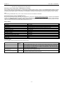
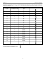
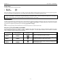
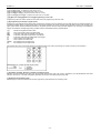
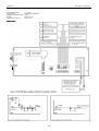
AUTOMATIC TELEPHONE ALARM DIALER
DIAL 07M
OPERATION AND INSTALLATION INSTRUCTION MANUAL
ROGER s.c.
DIAL 07M v1.1 29/03/2000
TABLE OF CONTENT
TABLE OF CONTENT .................................................................................................................................................................................................. 1
INTRODUCTION........................................................................................................................................................................................................... 2
Construction and Use of Dialer................................................................................................................................................................................ 2
INSTALLATION OF DIALER......................................................................................................................................................................................... 2
Connection of power supply..................................................................................................................................................................................... 2
Connection of telephone line.................................................................................................................................................................................... 2
Connection of input lines.......................................................................................................................................................................................... 2
Connection of PGM1 and PGM2 output lines.......................................................................................................................................................... 2
Switching on power supply voltage – EEPROM memory resetting .......................................................................................................................... 3
Default (manufacturing) settings of EEPROM memory ........................................................................................................................................... 3
Default settings........................................................................................................................................................................................................ 3
Acoustic signals....................................................................................................................................................................................................... 3
Hexadecimal notation system................................................................................................................................................................................... 4
LED indicators. ........................................................................................................................................................................................................ 5
LED indicator – „TEL.” (........................................................................................................................................................................................ 5
PREPARATION FOR DIALER OPERATION ............................................................................................................................................................... 5
DIALER OPERATION ................................................................................................................................................................................................... 5
READY mode .......................................................................................................................................................................................................... 5
ALARM mode .......................................................................................................................................................................................................... 5
ALARM RESETTING.............................................................................................................................................................................................. 6
NOTIFICATION WITH AN ALARM MESSAGE ..................................................................................................................................................... 6
PROCESS OF TELEPHONE CONNECTION ....................................................................................................................................................... 6
DETECTION OF PHONE PICK-UP ....................................................................................................................................................................... 6
DISABLING DETECTION OF PHONE PICK-UP – "BLIND" TRANSMISSION OF ALARM MESSAGE ............................................................. 6
CALLING DIALER FROM OUTSIDE...................................................................................................................................................................... 6
DOUBLE CALL FUNCTION ................................................................................................................................................................................... 6
DIALER CODES ..................................................................................................................................................................................................... 7
PROGRAMMING........................................................................................................................................................................................................... 7
METHODS OF TELEPHONE NUMBER PROGRAMMING .................................................................................................................................. 7
USER PROGRAMMING ............................................................................................................................................................................................... 8
INSTALLER PROGRAMMING.................................................................................................................................................................................... 10
TECHNICAL DATA ..................................................................................................................................................................................................... 12
DRAWINGS................................................................................................................................................................................................................. 12
-1-
ROGER s.c.
DIAL 07M v1.1 29/03/2000
INTRODUCTION
Construction and Use of Dialer
The Automatic Telephone Alarm Dialer is a device used for an automatic transfer of information on an occurrence of an alarm situation (fire, burglary,
etc.). The DIAL07M dialer is capable of transmitting a verbal message up to eight telephone subscribers and a text message up to two pager system
subscribers. All device operation configuring parameters and verbal alarm message are stored in EEPROM type memories and are not lost at a power
supply loss.
DIAL 07M enables:
recording a 15-second verbal alarm message,
recording of two additional verbal messages about state of A3 control input,
notification of up to eight telephone subscribers,
notification of up to two pager subscribers,
tone (DTMF) and decade (PULSE) dialing,
dialer connection by use of external call function,
monitoring of telephone line voltage and signalization of a voltage loss.
DIAL 07M is provided with:
main code enabling alarm resetting and device programming,
user code enabling only alarm resetting,
installer code enabling dialer configuring,
delay alarm input (A1 line),
instant alarm input of H24 type (A2 line),
control input (A3 line),
alarm signaling output (PGM1),
telephone line voltage loss signaling output (PGM2),
built-in capacitive microphone,
stereo mini-jack output for messages reproducing and listening to the telephone line.
INSTALLATION OF DIALER
The dialer should be hung on a vertical structure element (wall), far from any heat and moisture sources. All electric connections should be made prior
to power supply connection. After programming of the dialer, it is recommended to perform an alarm action simulation and check the notification
efficiency in practice.
Connection of power supply
The dialer power supply cables should be connected to terminals marked with +/- 12Vdc. The dialer requires DC power supply within a range from 11
to 15 Vdc. The dialer power supply system is protected with a polymer type electronic circuit breaker and does not need to be replaced after fault
condition. After the dialer is connected to power supply for the first time, it operates using the default (manufacturing) configuration settings, without
the recorded verbal messages.
Connection of telephone line
A telephone line should be connected to the dialer terminals marked with the caption "LINE". Other devices, which use the telephone line, should be
connected to the terminals "TEL". Such a connection guarantees that the devices connected to the terminals "TEL" cannot disturb the dialer when
operating with telephone line. The other devices (fax, modem etc.) using the telephone line can be also connected parallel with the dialer, i.e. to the
terminals "LINE", but in this case they can disturb or even stop the dialing and alarm notification process.
Connection of input lines
There are three inputs of the dialer: A1, A2 and A3. The A1 and A2 inputs are the alarm inputs. Input A3 has control function and can stop the alarm
and disabling monitoring of A1 line. All the dialer inputs have identical electric structure. Each of them can be configured as NO or NC. The alarm
inputs are usually triggered with a contact, but it can be also triggered through supplying a suitable voltage level. The line programmed as NO can be
triggered by supplying the power supply "minus" or by using NO switch. Line configured as NC can be triggered by using NC switch or by supplying
the power supply "plus", however when triggering by supply “plus” input should be previously connected with ground (“supply minus”) by a resistor
within the range from 0.5 to 2KΩ.
A1 input.
Delay alarm input. Triggering the input results in switching of the dialer into the alarm mode after the alarm time delay.
Monitoring of the A1 input does not operate when the dialer is in the programming mode or when the A3 line is triggered.
A2 input.
Instant alarm input. Triggering this input starts alarm without any delay. The dialer monitors the input regardless the condition of
the A3 line. Monitoring of the A2 line does not operate in the programming modes.
A3 input.
Controls monitoring of A1 input and can stop the alarm. When A3 is triggered monitoring of A1 line is switch off. Momentary
triggering of the A3 input during an alarm results in the alarm reset.
Connection of PGM1 and PGM2 output lines
The outputs are the "open collector" type universal outputs of 1A dc current capacity. The outputs are normally opened (which corresponds the high
impedance condition). When closed, the outputs supply the power supply "minus" potential. A maximum potential of +24V against the dialer power
supply "minus" can be connected to the programmable output. The programmable outputs are protected from overvoltage and are capable, without
any additional control elements (relays), of controlling the switching of most popular types of alarm signaling devices.
PGM1 output.
The output goes to ON state each time the dialer starts alarm. The output returns to OFF state after three minutes or after
alarm is reset (cancel). When the alarm has been switched on by entering a duress command, the PGM1 output is not closed
(the duress command – see the "ALARM" Mode section).
-2-
ROGER s.c.
PGM2 output.
DIAL 07M v1.1 29/03/2000
The output is switched ON when the dialer recognizes a 3 minutes lack of telephone line voltage. The output returns to OFF
state as soon as the telephone line voltage returns.
Switching on power supply voltage – EEPROM memory resetting
Each time after switching the power supply on, the dialer tests the position of the Z1 jumper. In case it is in the EEPROM RESET position, the dialer
resets all current settings in the EEPROM memory and assigns them the default (manufacturing) values, then the dialer goes to the READY mode. If,
during switching the power supply on, the Z1 jumper is in the NORMAL POSITION, the dialer skips the process of the EEPROM memory resetting.
Note!
After resetting the EEPROM memory, the Z1 jumper should be returned to the DEFAULT POSITION.
Default (manufacturing) settings of EEPROM memory
During the manufacturing process of the dialer, a set of parameters, whose name is default (manufacturing) settings, is entered into the EEPROM
memory. The settings are modified in the dialer programming or configuration process. The default values can be returned any number of times by
performing the EEPROM memory resetting procedure. EEPROM memory is usually reset in case of a loss of the previously programmed dialer
codes or in order to fix the technical trouble called "EEPROM memory error”.
Default settings
A1 line type
A2 line type
A3 line type
Alarm delay on A1 input
Dialing options 1
Dialing options 2
Number of external rings
Double call function time
“A3 triggered” message
“A3 normal” message
Alarm message
Text message to PAGER system station
User code
Main code
Installer code
:NO / SLOW
:NO / SLOW
:NO / SLOW
:0 seconds
DT signal waiting time 4 sec./ Don’t dial the number when no DT.
Pulse dialing (PULSE) / Detect telephone pick-up.
:0 (function off)
:0 minutes (function off)
:no message
:no message
:no message
:no message
:1111
:0000
:1234
Acoustic signals
During the dialer operation the following acoustic signals can occur:
NAME OF SIGNAL
Error signal
Error signal – identical codes
SYMBOL OF
SIGNAL
(-)
(--)
Encourage signal
(** **)
Operation completion signal
(*** ***)
INTERPRETATION OF SIGNAL
One long signal lasting about 2 sec. Occurrence of the signal informs about a programming
error or performing an invalid operation. The signal occurs also after entering the wrong code.
Two long signals. The signal occurs at an attempt of programming a code, which is identical
with the previously programmed one.
Two series of two short signals each. The encourage signal informs that the dialer awaits
entering a further part of a command or code.
Two series of three short signals each. The operation completion signal informs that the dialer
recognized and performed the entered command.
-3-
ROGER s.c.
DIAL 07M v1.1 29/03/2000
Hexadecimal notation system
With reference to some functions of the device, the HEXADECIMAL notation system (HEX in short) is used. In the system, a number can be
represented as a digit from the range 0,1…9 or a letter A, B, C, D, E and F. The number interpretation and programming methods in the HEX system
are shown in the following table.
NUMBER IN DECIMAL
SYSTEM
NUMBER IN
HEXADECIMAL SYSTEM
PROGRAMMING METHOD
(KEYS)
1
1
[1]
2
2
[2]
3
3
[3]
4
4
[4]
5
5
[5]
6
6
[6]
7
7
[7]
8
8
[8]
9
9
[9]
10
A
[*][0][*]
11
B
[*][1][*]
12
C
[*][2][*]
13
D
[*][3][*]
14
E
[*][4][*]
15
F
[*][5][*]
0
0
[0]
The drawing symbolizes all LED indicators are flashing.
-4-
LED INDICATOR PRESENTATION METHOD
ROGER s.c.
DIAL 07M v1.1 29/03/2000
LED indicators.
The dialer is provided with five LED indicators, four of which are used for indication of the dialer operation status or are used during programming.
The names of the indicators are: [ALARM][1] , [READY][2], [PROGRAM.][4] and [TEST][8]. The digits next to the LED indicators enable easy
interpretation of the numbers in the HEX system.
The method of interpretation of the LED indicator status is as follows:
ALARM LED is on
The dialer is in the alarm mode.
READY LED is on
The dialer monitors the A1 and A2 alarm inputs.
READY LED flushes
The A3 line is triggered, the dialer monitors only the A2 line, monitoring of the A1 line is off.
ALARM LED flushes
The dialer has been in the alarm mode and the alarm has not been reset yet by either entering the
proper code or triggering the A3 line.
ALARM and READY are on
The dialer is now counting time delay before alarm mode. Resetting the alarm during the delay
protects from commencing the telephone notification action and alarm signaling at the PGM1
output.
PROGRAM. LED is on
The dialer is in the user programming mode.
TEST LED is on
The dialer has recognized an occurrence of at least one technical problem.
TEST LED flushes
Since the time of the latest read-out of the technical problem, ([*][1]function), the dialer has
recognized a new technical problem.
PROGRAM. and TEST LED are on
The dialer is in the configuration mode.
In the programming mode, the LED indicators are additionally used for visualization of the entered parameter values. The LED indicators are assigned
with the numbers 1,2,4 and 8. Reading of the HEX number, which is displayed by the LED indicators, is obtained by adding the numbers located next
to the active LED indicators. The "zero" digit is indicated by flushing of all the LED indicators.
An example of reading of a number value indicated in the HEX code:
PROGRAM.[4] and TEST [8] indicators are on.
The number 8 corresponds the TEST indicator and the number 4 corresponds the PROGRAM indicator. The value of the presented HEX number is
therefore 8+4=12, which should be interpreted as the number "C" in the HEX system.
LED indicator – „TEL.” (
In addition to the mentioned LED indicators, the dialer is also provided with another (fifth) LED indicator, marked with a symbol of the telephone.
When the indicator is on, it means that the dialer is in telephone communication process and the telephone line is busy.
PREPARATION FOR DIALER OPERATION
In order to prepare the dialer for operation, electric connections should be made and then the installer programming mode should be entered and the
dialer operation configuration parameters should be set. After that, switch to the user programming mode and perform the necessary additional
programming operations.
DIALER OPERATION
READY mode
When in the READY mode, the dialer monitors the A1 alarm line and the A2 line. If the triggering condition occurs at the A1 input, dialer start time
delay before alarm and after the time delay has expired enters ALARM mode. . Triggering A2 input results in the immediate switching of the dialer to
the alarm mode. The READY mode is indicated by the READY LED indicator, which is on. If the A3 input is in the triggering mode, then the A1 input
monitoring is switched off. Blocking of the A1 line monitoring is indicated by flushing of the READY led. The condition of the A3 line has no effect on
the A2 input monitoring.
ALARM mode
The alarm mode is entered as a result of recognition of the A1 or A2 input triggering or it can be performed from the dialer keypad after an duress
command is entered. In the alarm mode, the dialer performs telephone connections with the numbers from the alarm telephone list and closes the
PGM1 output for 3 minutes. If the alarm has been started from the dialer keypad through entering the duress command, the PGM1 output, which
normally signalizes the alarm, is not switched on. The duress command is entered by entering the user main code or user code increased or
decreased by "1" in the last position.
-5-
ROGER s.c.
DIAL 07M v1.1 29/03/2000
An example of entering the duress command:
[Main code+1][#]
[Main code-1][#]
[User code+1][#]
[User code-1][#]
All the commands start the operation of the silent telephone notification, i.e. with the PGM1 output off.
Note! After completion of the telephone notification operation, the dialer automatically returns to the monitoring mode and is ready for new alarm.
ALARM RESETTING
Resetting of the alarm results in an interruption of the telephone notification operation and switch off PGM1 output. After the alarm is reset, the
ALARM LED stops flushing. The alarm can be reset from the dialer keypad using the commands [Main Code] [#] or [User Code] [#] or [Main
Code] [*] [#] . The latter command, in addition to resetting the alarm, makes the dialer switch to the user programming mode.
Note! The dialer allows for three attempts of entering the code. The third failed attempt results in blocking the keypad for 1 minute. During entering
the codes or other keypad manipulations the dialer does not interrupt the telephone notification operation nor stops the alarm input monitoring.
Important : Resetting the alarm can be performed from a remote location through a momentary or permanent triggering of the A3 line.
NOTIFICATION WITH AN ALARM MESSAGE
The dialer try to get a double connection with each of the pre-programmed telephone subscribers specified in the alarm list. A telephone connection is
qualified as a "notification", if the dialer, based on an analysis of electric signals in the telephone line, recognizes the moment of phone pick-up by
the called subscriber and performs a transmission of the alarm message. If option "Don't detect for telephone pick-up" (Installer Programming
function [*][6]), each dial attempt is treated as a notification, no matter if the subscriber has or has not picked up the phone. Telephone connections
are performed in four dialing cycles. In each dialing cycle the dialer performs one attempt with every telephone number. The telephone connections
are performed according to their sequence on the telephone list. The subscribers, who have receive twice notification are skipped during the further
notification process. The pager system subscribers are selected as the first priority, i.e. prior to the numbers of the subscribers notified with a verbal
message. A text message (see the User Programming function [*][9]) is transmitted to the pager system subscribers. A notification to the pager
system subscribers is acknowledged as soon as the dialer receives a signal, which confirms the receipt of the text message transmitted by a pager
system station.
PROCESS OF TELEPHONE CONNECTION
After connecting into the telephone line, the dialer awaits an answer signal from a telephone exchange (DT) and when the signal has been recognized,
the dialer starts to dial the number. After dialing, the dialer awaits an answer (phone pick-up) of the dialed subscriber and after that performs a double
transmission of the alarm message and goes to a connection with another alarm number. The maximum time of waiting for dial tone of a telephone
exchange (DT) is set up in the Installer Programming (function [*][5]) and can be set at 4 or 8 sec. When in the required time of 4 or 8 sec. the dial
tone has not been recognized, the dialer goes to dialing another telephone number. If the option "Dial the number despite no DT signal" is activated,
the dialer ignores the lack of dial tone signal and despite of it dials a phone number and transmit message.
DETECTION OF PHONE PICK-UP
Dialer detects phone pick-up of dialed subscriber after:
disappearance of “returned call signal” or
voltage polarity change in telephone line
Note! A telephone connection, in which an answer of the called subscriber has been recognized by one of the above described manner, is qualified
as successful and the subscriber as having been notified once.
DISABLING DETECTION OF PHONE PICK-UP – "BLIND" TRANSMISSION OF ALARM MESSAGE
In justified cases, during the dialer configuration, the installer can switch off option "Don't detect phone pick-up ". Enabling the option results in an
unconditional transmission of the alarm message directly after dialing the telephone number. When the option is on, the dialer recognizes each
attempt of a telephone connection as a notification. When the option is on, the dialer dials each of the pre-programmed alarm numbers twice no
matter if the subscriber has or has not picked up the phone.
Note! When the option "Don't detect phone pick-up" is on, it is recommended to program the same telephone number in two or more positions to
enhance the notification certainty.
CALLING DIALER FROM OUTSIDE
The dialer is capable of accept the phone calls from outside. During the configuration, the installer defines the number of rings, after recognition of
which the dialer has to start handling an external telephone call. (See the Installer Programming function [*][7]). The dialer, after recognition of the
required number of rings, switches into the telephone line and transmits a verbal message corresponding to the current condition of A3 line. When A3
is triggered dialer transmit message “A3 triggered” or when line is in normal condition dialer transmit message “A3 normal” (recording of this
messages see function [*][9][1] and [2] in Installer programming mode). If an alarm occurred during the last READY cycle, the dialer additionally to
the messages about A3 line plays the alarm verbal message, the same as during the alarm action. After transmitting the messages, the dialer
automatically disconnects telephone line. Transmission of the “A3 triggered” message is preceded with three long acoustic signals (- - -), whereas
transmission of the “A3 normal” message is preceded with a series of three acoustic signals composed of short pulses (*** *** ***).
DOUBLE CALL FUNCTION
In case the dialer recognizes in the telephone line the number of rings, which is equal with the number pre-declared in the configuration, then no
matter if the Double Call function is on or off, the dialer hooks into the telephone line and handles the call. However, if the recognized number of rings
is smaller than the pre-set value in the configuration and the Double Call function is on, the dialer starts the process of counting pre-declared time
delay. If, during this delay the dialer recognizes rings again, it does not wait for the required number of rings, but immediately after the second ring
connects into the telephone line and handles the connection. This function enables other devices, which are connected to the telephone line along
with the dialer, the priority access to receive a call and provides that any third parties do not see the presence of the dialer in the telephone line.
Note! Enabling of the Double Call function is done through programming the time delay (the Installer Programming [*][7] value bigger than zero). The
Double Call function is disabled through programming the delay at 000.
Note! Please remember that the Double Call function can operate properly only if any other devices, which use the telephone line along with the
dialer, do not intercept a call after recognition of less than two rings, because it would disable the dialer to intercept the call.
-6-
ROGER s.c.
DIAL 07M v1.1 29/03/2000
DIALER CODES
The dialer is provided with the following codes:
•
•
•
Main code
User code
Installer code
[MC],
[UC],
[IC].
Each of the codes can have the length from 4 to 8 digits. The main code enables resetting the alarm and entrance to the user programming mode.
The user code enables only resetting the alarm. The installer code enables entrance to the installer programming mode.
Note!
The codes must be different. The dialer does not allow programming of two identical codes. In case of an attempt of programming a code identical
with another, already existing code, the dialer signalizes the code programming error (error signal - - ).
PROGRAMMING
The dialer is provided with two programming modes: "User Programming" mode and "Installer Programming" mode. The "User Programming" mode
can be accessed from the READY or ALARM mode using the command [Main Code] [*] [#]. The "Installer Programming" mode can be accessed
only from the user programming mode using the command [*] [0] [Installer Code] [#].
Note!
In either of the programming modes the dialer does not monitor the input lines nor answers external calls.
METHODS OF TELEPHONE NUMBER PROGRAMMING
The dialer enables programming two telephone numbers to PAGER system stations and eight alarm numbers to subscribers notified with a verbal
alarm message. Each number can consist of 16 digits. In addition to the digits 0, 1..9, some special characters can be inserted in a telephone
number. The dialer accepts the following special characters:
SPECIAL
CHARACTER
HEX B
METHOD OF CHARACTER
PROGRAMMING
LED INDICATOR
STATUS
This character is used for switching to another (alternate) dialing
system, i.e. from DTMF to PULSE or inversely.
[*][1][*]
HEX C
[*][2][*]
HEX D
[*][3][*]
CHARACTER FUNCTION
This character introduces a 4-second interruption in dialing. After
the break has elapsed, the dialer resumes dialing.
The character makes the dialer wait for a dial tone (DT) signal.
Programming the character results in stopping the dialing process
until a DT signal occurs.
-7-
ROGER s.c.
DIAL 07M v1.1 29/03/2000
USER PROGRAMMING
The user programming mode is entered from the monitoring mode or alarm mode using the command:
[Main Code][*][#]
After the mode has been entered, the dialer turns on the PROGRAM LED. The following functions are available in the user programming mode:
[*] [1] [#] – Technical problem read-out.
After entering the function ([*][1]), the dialer signalizes the existence of recognized technical problems through turning on the corresponding LED
indicators. A return from the function is done by depressing the key [#].
PROBLEM CODE
METHOD OF LED
INDICATOR
PRESENTATION
MEANING OF PROBLEM
1
A telephone line voltage loss. The problem disappears when the telephone line voltage is back.
Recognition of the error is additionally signalized on PGM2 output.
2
A telephone exchange does not respond (no DT signal). The problem disappears as soon as a
DT signal occurs at the next telephone connection.
4
8
This problem indicates that some errors in the data memory (EEPROM) occurs. In consequence,
the dialer malfunctions may occur. In order to solve the problem, the EEPROM memory should be
reset and the dialer should be programmed again. If reprogramming does not solve the problem,
the dialer should be returned to the service for repair.
The problem indicates an error in the program memory (ROM). If such a problem is found, the
dialer should be returned to the service for replacement of the ROM memory system.
[*] [2] [N] [Telephone number] [#] – Programming of N-th alarm number
In place of the letter N, enter a digit from 1 to 8, which determines which of the numbers will be programmed. The number programming completion is
obtained with the character [#]. Each entered digit or special character is presented on the LED indicators in the HEX system. A number is deleted
from the alarm telephone list by programming it as a blank number.
Example:
[*][2][4][1234566789][#] – the fourth alarm number is programmed
[*][2][4][#] – the fourth alarm number is erased
[*][2][N][#] – the N-th alarm telephone number, [N]=1..8
[*] [3] [N] ( [*] ) [#] – Read-out of N-th alarm number
After entering the function, the LED indicators present the first digit of the telephone number in the HEX system. The key [*] provides a skip to the
presentation of the next digit of the number. The function is abandoned automatically after the last digit of the telephone number is displayed or may
occur earlier after using the key [#].
[*] [4] ( [#] ) – Recording of alarm message
Immediately after depressing the key [4], the dialer begins recording of an alarm message. The message should be recorded by speaking from a
distance of about 20 cm from the dialer keypad. The message recording is completed and the function is abandoned when the available recording
time (15 sec.) has elapsed or it can occur earlier, after depressing the key [#].
[*] [5] ( [#] ) – Playback of alarm message
Immediately after depressing the key [5], the dialer begins to play back the alarm message recorded in the memory. The message can be listened to
using a set of headphones plugged into the dialer headphone output. The headphones need to be equipped with a "mini-jack stereo" of 3.5 mm
diameter. The end of playback and exit from the function is performed automatically after playing back the complete message or may occur in any
moment by using the key [#].
[*] [6][N] [Telephone number] [#] – Programming of pager system telephone numbers
The character [N] should be overwritten with the digit [1] or [2] depending on that whether the first or the second pager system subscriber telephone
number should be programmed. Each entered digit or character are presented by the LED indicators in the HEX system. Removing a number from
the list is performed by programming the number as a blank one.
Example:
[*][6][2][12345678][#] – programs the second number to a pager system subscriber.
[*][6][1][#] – erased the first number to a pager system subscriber.
[*] [7] [New main code ] [#] [New main code] [#] – Programming of main code.
After depressing the key [7], the programmer has to make a double entry of the new main code. Each time the new code has to be ended with the
character [#]. When the two codes are identical, the new code is stored in the memory, otherwise a programming error is signalized and the function
is abandoned. The code length must stay within the range from 4 to 8 digits. The digits of the entered code are displayed by the LED indicators in the
HEX system.
-8-
ROGER s.c.
DIAL 07M v1.1 29/03/2000
Example:
[*][7][1212][#][1212][#] – programs the main code as 1212
[*][7][12123][#][12123][#] – programs the main code as 12123
[*][7][121234][#][121234][#] – programs the main code as 121234
[*][7][12123434][#][12123434][#] – programs the main code as 12123434
[*] [8] [New user code] [#] [New user code] [#] Programming of user code
Programming of the user code is carried out in the same manner as programming of the main code.
[*] [9] Programming of message to pager system
Programming of the message to the pager system is performed by entering a series of characters from the dialer keypad. The entered characters are
transmitted as DTMF digits to a pager system station. Pager system operators use various message coding algorithms. Coding of the message to the
pager system station should be performed according to the system operator manual, treating the dialer keypad in the same way as the telephone
keypad. The method of message programming compliant with the POLPAGER system is presented below:
[*][*]
[0][*]
[N][*]
[N][#]
[N]
[*]
[0]
[0][#][#]
[#]
- switches the keypad to the letter mode,
- return from the letter mode to the digital mode,
- in the letter mode it gets the left letter of the keypad,
- in the letter mode it gets the right letter of the keypad,
- in the letter mode it gets the middle letter of the keypad,
- enters a space in the digital mode,
- enters a space in the letter mode,
- the message end in the letter mode,
- the message end in the digital mode,
After entering the function, the keypad operates in the digital character entry mode. The message can consist of maximum 128 characters.
[*] [0] [Installer Code][#] – Entrance to installer programming mode
After the command is entered, the dialer goes to the installer programming mode. The mode is signalized by the LED PROGRAM. and TEST
indicators, which are on. The dialer configuration parameters are set up in the installer programming mode.
[*] [#] Exit from programming mode
After entering the command, the dialer exits the user programming mode and enters the monitoring mode.
-9-
ROGER s.c.
DIAL 07M v1.1 29/03/2000
INSTALLER PROGRAMMING
In this mode, the dialer configuration is set up. The installer programming mode is entered exclusively from the user programming mode and is
performed after entering the command [*] [0] [Installer code] [#]. After entering the mode, the dialer turns on the PROGRAM. and TEST. LED
indicators. The following functions are available in the installer programming mode:
[*][1][N][#] – A1 input type
The letter [N] should be replaced by entering the digit [1],[2],[4] or [8]. After entering the function, the LED indicator, which corresponds the current
active option, is on. The programmer, by depressing the suitable key (1,2,4 or 8) performs the option change. After switching on the new option, the
corresponding LED indicator is automatically turned on. The exit from the function and entering the changes to the memory is performed by
depressing the key [#]. The options mean as follows:
[1]- NO/SLOW type line
[2]- NC/SLOW type line
[4]- NO/FAST type line
[8]- NC/FAST type line
Example:
[*][1][2][#] programs the A1 line as the NC/SLOW type line.
NOTE!
A slow line requires a pulse longer than 2 sec. for triggering. A fast line requires a pulse longer than 0.2 sec.
[*][2][N][#] – A2 input type
Programming identical as for the A1 input.
[*][3][N][#] – A3 line type
Programming identical as for the A1 input.
[*][4][XYZ][#] – Alarm start time delay
The time delay refers only to the A1 input line. The value entered in place of the [XYZ] characters can be from 0 to 255 and means the time delay in
seconds. After entering the function, the PROGRAM LED indicator flushes. The programmer enters digits, each time a subsequent digit is entered, it
is presented by the LED indicators. After entering the third digit (Z), the function should be abandoned by depressing the key [#]. When the value
[XYZ]=[000] is programmed, the alarm is started immediately after recognition of the A1 alarm input triggering.
Example:
[*][4][120][#] - sets the alarm start time delay at 120 seconds
[*][4][012][#] - sets the alarm start time delay at 12 seconds.
[*][4][12][#] - sets the alarm start time delay at 12 seconds.
[*][5][N][#] – Dialing options 1
When the function is entered, the LED indicator, which corresponds the currently active option, is on. By depressing the proper key [1],[2],[4] or [8],
the programmer selects a new option. After switching on the new option, the corresponding LED indicator is automatically turned on. The exit from the
function and storing the changes in the memory is performed by depressing the key [#]. The options mean as follows:
[1] - DT signal waiting time 4 sec./ Don’t dial the number when no DT.
[2] - DT signal waiting time 8 sec./ Don’t dial the number when no DT.
[4] - DT signal waiting time 4 sec./ Dial the number if no DT.
[8] - DT signal waiting time 8 sec./ Dial the number if no DT.
DT –Dial Tone
Example:
[*][5][4][#] sets the DT signal waiting time at 4 sec. and makes the dialer select the telephone number and transmit the message, despite the lack of
the signal.
[*][6][N][#] – Dialing options 2
When the function is entered, the LED indicator, which corresponds the currently active option, is on. By depressing the proper key [1],[2],[4] or [8],
the programmer selects a new option. After switching on the new option, the corresponding LED indicator is automatically turned on. The exit from the
function and storing the changes in the memory is performed by depressing the key [#]. The [N] digit means as follows:
[1] - Pulse dialing (PULSE) / Detect phone pick-up .
[2] - Pulse dialing (PULSE) / Don't detect phone pick-up.
[4] - Tone dialing (DTMF) / Detect phone pick-up.
[8] - Tone dialing (DTMF) / Don’t detect phone pick-up .
Example:
[*][6][4][#] switches to the tone (DTMF) dialing system and sets detect telephone pick-up option on.
[*][7][N][#] – Number of rings before answer
The letter [N] should be replaced by entering a digit from the range from 0 to 9. After the function is entered, the PROGRAM. LED indicator pulses.
The programmer enters the desired parameter value in place of the letter [N], the value is automatically displayed by the LED indicators. The exit from
the function and the entry of the changes into the memory is obtained by depressing the key [#]. When the value N=0 is programmed, the dialer does
not answer any external calls.
Example:
[*][7][4][#] sets the external call answering to activate after recognition of four rings.
- 10 -
ROGER s.c.
DIAL 07M v1.1 29/03/2000
[*][8][XYZ][#] – Double call function time
The value entered in place of the characters [XYZ] must stay within the range from 0 to 255 (seconds). After entering the function, the PROGRAM.
LED indicator pulses. The programmer enters the value [XYZ], each time a subsequent digit is entered, the dialer presents it on the LED indicators in
the HEX system. After entering the third digit (Z), the function is abandoned by depressing the key [#]. When the value [XYZ]=[000] is programmed,
the Double Call function is disabled, which means that each time when the dialer recognizes the pre-programmed number of rings, it hooks into the
telephone line and transmits a message on the dialer status and, if applicable, occurrence of the alarm.
Note!
The double call function allows other devices, which use the telephone line along with the dialer, to get priority to answer an external call. When the
function is used, it is recommended to set the Double Call time value at a number from 30 to 180 seconds.
Example:
[*][8][045][#] - sets the DC function activation time at 45 seconds.
[*][8][45][#] - sets the DC function activation time at 45 seconds.
[*][8][5][#] - sets the DC function activation time at 5 seconds.
[*][9][1] – Recording message “A3 normal”
Immediately after depressing the key [1], the dialer starts to record the message. The message should be recorded by speaking from the distance of
about 20 cm towards the dialer keypad. After the recording time (2 seconds) has expired, the dialer automatically plays back the message. Due to a
short time of recording (2 sec.), it is necessary to keep the message short, e.g. "MONITORING ENABLE” or "MONITORING ON”. In case the
recorded message is too silent or is significantly distorted, the recording should be repeated and the programmer should speak louder.
[*][9][2] – Recording message “A3 triggered”
Immediately after depressing the key [2], the dialer starts to record the message. The message should be recorded by speaking from the distance of
about 20 cm towards the dialer keypad. After the recording time (2 seconds) has expired, the dialer automatically plays back the message. Due to a
short time of recording (2 sec.), it is necessary to keep the message short, e.g. "MONITORING DISABLE” or "MONITORING OFF”. In case the
recorded message is too silent or is significantly distorted, the recording should be repeated and the programmer should speak louder.
[*] [0] [New Installer code ] [#] [New Installer code] [#] – Programming of new Installer code.
After depressing the key [0], operator has to make a double entry of the new installer code. Each time the new code has to be ended with the
character [#]. When the two codes are identical, the new code is stored in the memory, otherwise a programming error is signalized and the function
is abandoned. The code length must stay within the range from 4 to 8 digits. The digits of the entered code are displayed by the LED indicators.
[*] [#] Exit from installer programming mode
After entering the command, the dialer abandons the installer programming mode and goes to the monitoring mode.
- 11 -
ROGER s.c.
DIAL 07M v1.1 29/03/2000
TECHNICAL DATA
Power supply voltage
Supply current
Operating temperature range
Weight
Dimensions (L x W x H)
11..15 Vdc
typical 40mA / max.100mA
0..50 C°
approx. 0.27 kg
215 x 95 x 27
DRAWINGS
- 12 -