1
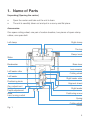
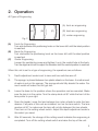
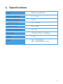
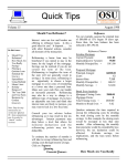
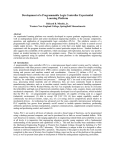
Notification
Dear Users,
Thank you for your purchase of AG 1000 Auto Groover. Please take time to read our
user’s manual carefully before use.
This guarantees you to make full use of this unit and prolongs the operation life of
this unit.
Precautions
If you have detected abnormal heat, smoke, noise or smell, immediately stop using
the product.
In the event of an abnormality, turn off the power and disconnect the power plug from
the power socket. Continuing to use the product may result in electric shock or fire.
Observe the instructions given below regarding the power cable:
•
•
•
•
•
•
Be sure to use the supplied or specified power cable.
Do not modify, forcibly bend, kink or pull the power cable.
When disconnecting the power cable from the AC outlet, be sure to hold the cable
by the plug.
Pulling the cable may cause wire breakage or shot circuit, resulting in fire or electric
shock.
Do not connect or disconnect the plug of the power cable to/from the AC outlet
using wet hands.
Doing so may result in electric shock.
Do not touch the product with wet hands while the power cable is connected
to the AC outlet.
Doing so may result in electric shock.
If the product will not be used for a long period, disconnect the power cable
from the power source. Leaving the cable connected to the power socket for
a prolonged period will consume electricity and may result in heating.
Content
1.
Name of Parts ................................................................................................4
2.
Operation .......................................................................................................5
3.
Maintenance .................................................................................................6
4.
Specifications ................................................................................................7
1. Name of Parts
Unpacking (Opening the carton)
•
•
Open the carton and take out the unit in foam.
The unit is carefully taken out and put in a roomy and flat place.
Accessories
One spare cutting wheel, one pair of carbon brushes, two pieces of spare clamp
rubber, one spare belt.
Left clamp
Right clamp
The top
Clamp knob
Slider
Breakwater
Base lever
Lens receiver
Left leader roller
Cutting wheel
Left leader
Right leader roller
Positioning knob
Aligment shank
Zero adjustment
knob
Depth adjustment
scale
Lens turning switch
Right leader
Positioning screw
Spring
Cutting wheel
switch
Fig. 1
4
2. Operation
All Types of Engrooving
(A) front arc engrooving
(A)
(B)
(C)
(B) back arc engrooving
(C) center engrooving
Fig. 2
(A)
(B)
(C)
Front Arc Engrooving
Turn anticlockwise the positioning knob on the lower left until the ideal position
is reached.
Back Arc Engrooving
Turn clockwise the positioning knob on the lower left until the ideal position
is reached.
Center Engrooving
Loosen the positioning screw and tighten it up in the central hole at the back.
Turn the alignment knob to adjust the deviation until the central position is reached.
When this unit is set to a type of engrooving, the operations are as follows:
1.
Depth adjustment scale is set to zero and two switches are off.
2.
The sponge is placed between two plastic sheets on the base. A small amount
of water is put on the sponge. The sponge should fully absorb the water. Too
much water will make this unit get wet.
3.
Lower the base to the position where the operation can be executed. Make
sure the lens is in the center. Turn the clamp knob at 90° while the front of the
lens points to your right.
4.
Open the leader. Lower the lens between tow nylon wheels to enter the lens
receiver. If all parts of this unit are installed, turn on the lens switch. The lens
revolves at 90° to make sure the lens will not slip between the two wheels.
Then turn on the cutting wheel switch. Adjust the depth adjustment scale to
the extent you need.
5.
After 60 seconds, the change of the cutting sound indicates the engrooving is
completed. Turn off the cutting wheel switch and raise the top of the unit.
5
Notice
Please take two steps if you apply the depth engrooving to the hard lens. First, the
engrooving goes a half depth. Second, the engrooving goes the other half depth.
3. Maintenance
•
Sponge:
Often clean the sponge. Before use, the sponge should fully absorb the water.
When the sponge is broken, replace it as soon as possible. After use, clean the
sponge.
•
Slider:
Keep the slider clean with a cloth in order to make the top of the unit move
smoothly. Smear oil on the slider.
•
Replace the cutting wheel:
Turn off the power and insert a thin iron stick into the hole of the shaft. The
shaft is locked and unable to move. The cytting wheel can be easily removed
and reinstalled. See Fig. 3.
•
Replace the clamp rubber:
Open the lens clamp, move the left clamp and the right clamp to remove the
clamp rubber. Then put in a new pair of rubber.
Fig. 3
6
4. Specifications
Lens
Mineral or plastic lens
Depth of engrooving
0 - 0. 7mm
Width of engrooving
0.6mm
Thickness of lens
1.5 - 11.0mm
Diameter of lens
28 - 70mm
Duration of engrooving
App. 60s
Dimensions
170 (W) x 210(L) x 150(H)mm
Weight
2. 7kg
Power
100 - 120V/60HZ or
200 - 240V/50HZ AC, 95W
7
LUXVISION is not responsible or liable for indirect, special or consequential damages arising out of or in
connection with the use or performance of the product or damages with respect to any economic loss,
loss of property, loss of revenues or profits, loss of enjoyment or use, costs of removal or installation or
other consequential damages of whatsoever nature. Some states do not allow the exclusion or limitation
of incidental or consequential damages. Accordingly, the above limitation may not apply to you.
Every effort has been made to ensure the accuracy of this manual. However, LUXVISION, makes no
warranties with respect to the documentation and disclaims any implied warranties of merchantability
and fitness for a particular purpose. LUXVISION, Inc. shall not be liable for any errors or for incidental or
consequential damages in connection with the furnishing, performance, or use of this manual or the examples
herein. The information in this document is subject to change without notice.
8