1
The Optronics 6ES Patternless Edger System
User’s Manual
October 20, 2004
Rev. 1.082
Warnings, Cautions, and Notes
as Used in this Publication
Warning
Warning notices are used in this publication to emphasize that hazardous voltages, sharp
edges, or other conditions that could cause personal injury exist in this equipment or may
be associated with its use.
In situations where inattention could cause either personal injury or damage to
equipment, a Warning notice is used.
Caution
Caution notices are used where equipment might be damaged if care is not taken.
Note
Notes merely call attention to information that is especially significant to understanding and
operating the equipment.
This document is based on information available at the time of its publication. While efforts
have been made to be accurate, the information contained herein does not purport to cover all
details or variations in hardware or software, nor to provide for every possible contingency in
connection with installation, operation, or maintenance. National Optronics assumes no
obligation of notice to holders of this document with respect to changes subsequently made.
©Copyright 2004, National Optronics
All Rights Reserved.
Safety Reminders
•
DO NOT operate this machine until you have read and understood this manual—if operating for the
first time; ask your supervisor or a qualified operator for help.
•
DO NOT attempt to bypass or circumvent the built-in safety features: the safety switches and the chip
chute cover. They are in place for operator protection—any alteration, removal or damage can cause a
serious safety hazard. Doing so will void your warranty.
•
DO NOT attempt changing cutters or any machine maintenance or repair until you have turned the
cutter motor switch to OFF.
ROTATING CUTTERS CAN CAUSE SERIOUS INJURY.
USE EXTREME CAUTION WHEN WORKING NEAR THE CUTTERS.
•
Plug unit into a grounded receptacle ONLY! Do not cut off the ground prong or use any cord or adapter
without a ground prong.
•
Always assume that the power and motor switch are ON—do not attempt any cutter change or
maintenance until you have verified they are OFF.
•
When changing inserts, always make sure that the insert clamp(s) are tight before starting the machine.
•
Never turn the machine or the cutter motor on while someone is performing maintenance or repair.
•
Always wear safety glasses with side shields when servicing the machinery.
•
Never operate this machine while on medication which may affect sight or coordination.
•
Under normal operation, the 6ES produces sound levels within the requirements of the Occupational
Safety and Health Administration Regulations. However, the use of the 6ES with other noise producing
equipment may raise sound levels to a degree where hearing protection should be worn by the user.
Therefore, if the users’ environmental circumstances cause a projected noise dose of 85% or more
(appropriate testing is recommended), the use of hearing protection is highly recommended. Further,
sensitivity to noise levels may depend on the individual user. While the 6ES operates within accepted
noise standards, the use of hearing protection should be considered by the user should the user experience
discomfort or abnormal hearing sensations during use.
•
The 6ES should be lifted very carefully by two people. Before attempting to move or lift the edger,
ensure that all connections (electrical, communications, and vacuum) have been disconnected from the
edger. To lift the edger, each person should carefully lift the edger from the bottom of each edge, using
both hands.
THINK SAFETY FIRST—ALWAYS PRACTICE SAFE WORK HABITS.
i
Preface
Content of This Manual
Chapter 1.
Prerequisites: Includes National Optronics contact information, requirements
for use such as electrical supply and operating conditions, and general
specifications of the Optronics 6ES Patternless Edger System.
Chapter 2.
Getting Started: Includes instructions on initial installation and daily
maintenance.
Chapter 3.
Commonly Performed Tasks: Includes instructions for changing the blade,
verifying size and bevel placement, updating the software code, and changing the
vacuum bag and paper filter.
Chapter 4.
Operating the 6ES (Standard Operation): Includes tasks performed while
using the 6ES in a standard operation, such as pulling down a job, edging
(roughing and finishing), polishing, grooving, and safety beveling.
Chapter 5.
Calibrating the 6ES: Includes instructions on all aspects of calibration.
Chapter 6.
Performing As Needed Maintenance: Includes instructions for performing nondaily maintenance tasks. (For daily maintenance tasks, refer to Chapter 2.)
Chapter 7.
Advanced Configuration & Special Considerations: Includes instructions on
less commonly performed tasks with the 6ES Edger System such as changing
display options on the Job Screen, creating alternate selections on the Blank
Materials screen, reading and interpreting data collected in the Log Screen, and
using less common calibration settings. These tasks are generally performed by a
lab manager or a National Optronics technician and are password protected.
Appendix A.
Screen Field Definitions: Includes reference information including definitions
of the fields on the screens you will see on the 6ES’s monitor.
Appendix B.
6ES System Messages: Describes and gives more detail about the messages you
will see on the 6ES’s monitor (warnings, information, etc.).
Appendix C.
Spindle Assembly: Shows an exploded view of the spindle Assembly.
Appendix D.
Statement of Warranty: Includes the Warranty Statement for the 6ES.
iii
Preface
Changes from the Previous Edition
The 1.04 edition includes a change to the takeoff value when calibrating the Wheel 2 Size Bias.
The suggested takeoff is now 0.30 since this is what we use in the dry-wet cycle.
The 1.05 edition includes two new fields on the Advanced Setup Screen and on the Servo Screen,
neither of which should be adjusted without the advice of an Optronics technician.
The 1.06 edition includes a correction to the drawing in Appendix C.
The 1.07 edition includes a new drawing of the Accessory Kit, which now includes a one-ounce
cup to be used when mixing Tri-Cool with distilled water prior to filling the water bottle—refer to
Chapter 2 for more information.
The 1.08 edition includes a modified drawing of the Accessory Kit in Chapter 2 and new
information about A/R coating for thin lenses—refer to Chapter 7 for more information. There are
also three new materials shown on the Blank Materials Screen, field definitions supplied in
Appendix A. In addition, this software version includes a new method for cleaning the Polishing
Wheel—refer to Chapter 3 for details.
The 1.081 edition includes a small change to the Blank Materials Screen and the Advanced Setup
Screen. Previously, there was a pressure field on the Advanced Setup Screen. This functionality
has been moved to the Blank Materials Screen (field definitions supplied in Appendix A). This
change simplifies and improves the calibration of the Polishing Wheel—refer to Chapter 5 for
details.
The 1.082 edition includes a small change to the Accessory Kit drawing in Chapter 2 and
additional reference material (part lists) in Appendix C.
This manual was released with Software Version 1.11. Future software
upgrades do not necessarily affect the manual. Call technical support if you
feel you need a newer manual.
iv
Contents
Chapter 1
Before You Begin ................................................................................................ 1-1
Before You Begin ................................................................................................. 1-1
General Description ........................................................................................ 1-1
For Further Assistance .................................................................................... 1-1
To Order Parts:.............................................................................. 1-1
For Technical Assistance: ............................................................. 1-2
Conventions Used in This Manual.................................................................. 1-3
Requirements for Use...................................................................................... 1-3
115 VAC 60 Hz 20A Electrical Supply .............................................. 1-3
Operating Conditions .......................................................................... 1-4
General Specifications .................................................................................... 1-4
Cutters ................................................................................................. 1-4
Cutter Motor........................................................................................ 1-4
Bevel Placement.................................................................................. 1-4
Vacuum ............................................................................................... 1-5
Lens Materials..................................................................................... 1-5
Statement Against Misuse................................................................... 1-5
Chapter 2
Getting Started & Daily Maintenance .............................................................. 2-1
Section 1: Initial Installation............................................................................ 2-1
Setting Up the Cabinet .......................................................................................... 2-2
Preparing the Workbench...................................................................................... 2-2
Setting Up the Vacuum Unit ................................................................................. 2-3
Assembling the Vacuum ................................................................................. 2-3
Setting Up the Vacuum Inside the Cabinet ...................................................... 2-3
Setting Up the 6ES ................................................................................................ 2-4
Placing the 6ES on the Cabinet....................................................................... 2-4
Removing the Shipping Bracket ..................................................................... 2-5
Connecting the 6ES to an Electric Outlet ....................................................... 2-5
Filling the Coolant Reservoir (the Water Bottle)............................................ 2-6
Wetting the Sponge for Initial Use ................................................................. 2-7
Powering Up and Calibrating the Probe ......................................................... 2-8
Setting Up Communications for Job Information........................................... 2-9
Overview ....................................................................................... 2-9
Comm Settings ................................................................................................ 2-9
Arcnet Connection ........................................................................ 2-9
Machine Node ID.......................................................................... 2-9
Protocol ......................................................................................... 2-9
Com1 and Com2 Connection ...................................................... 2-10
Baud Rate .................................................................................... 2-10
Protocol ....................................................................................... 2-10
v
Contents
OMA Init Level........................................................................... 2-10
Max TRCFMT ............................................................................ 2-10
Changing Communications Settings ............................................................. 2-10
Section 2: Daily Cleaning & Other Daily Maintenance of the 6ES ............ 2-11
Daily Cleaning of the 6ES................................................................................... 2-11
Other Daily Maintenance .................................................................................... 2-12
Checking the Probe Tip for Wear ................................................................. 2-12
Checking the Clamp Pad............................................................................... 2-12
The Accessory Kit............................................................................................... 2-13
Chapter 3
Commonly Performed Tasks ............................................................................. 3-1
Changing the Cutter Blade .................................................................................... 3-1
Changing the Groover Wheel................................................................................ 3-4
Sponge Replacement............................................................................................. 3-6
Verifying Size and Bevel Placement..................................................................... 3-8
Changing the Vacuum Bag ................................................................................... 3-9
Air Intake Maintenance....................................................................................... 3-10
Cleaning the Polishing Wheels ........................................................................... 3-11
Backing Up the System....................................................................................... 3-12
Saving Setup Numbers........................................................................................ 3-13
Updating Software .............................................................................................. 3-14
Chapter 4
Operating the 6ES (Standard Operation)......................................................... 4-1
Pulling Down a Job ............................................................................................... 4-1
Job Screen Display Variations ........................................................................ 4-2
Edging, Polishing, Grooving and Safety Beveling ............................................... 4-4
Chapter 5
Calibrating the 6ES............................................................................................. 5-1
Calibrating the Probe............................................................................................. 5-2
Calibration: Overview........................................................................................... 5-3
Calibrating Axis, Size, and Bevel ......................................................................... 5-4
Calibrate Trace Size Adjustment .......................................................................... 5-5
Calibrating the Polishing Wheels.......................................................................... 5-6
Calibrating Wheel 1 ........................................................................................ 5-7
Calibrating Wheel 1 Bevel .................................................................. 5-7
Calibrating Wheel 1 Size .................................................................... 5-9
Calibrating Wheel 2 ...................................................................................... 5-10
Calibrating Wheel 2 Bevel ................................................................ 5-10
Calibrating Wheel 2 Size .................................................................. 5-12
Calibrating Poly Bevel Polish ....................................................................... 5-13
vi
Contents
Calibrating Bevel Polish for CR-39 .............................................................. 5-15
Rimless Lens Calibration .................................................................................... 5-16
Calibrating Wheel 1 Rimless Size ................................................................ 5-16
Calibrating Wheel 2 Rimless Size ................................................................ 5-17
Calibrating Poly Rimless Polish ................................................................... 5-18
Calibrating CR-39 Rimless Polish ................................................................ 5-19
Calibrating the Safety Bevel ............................................................................... 5-20
Adjusting the Water Flow ................................................................................... 5-21
Calibrating the Groover....................................................................................... 5-22
6ES Polish Calibration Quick Reference Guide ................................................. 5-24
Beveled Lens Calibration.............................................................................. 5-24
Calibrate Wheel 1 Bevel ................................................................... 5-24
Calibrate Wheel 1 Size...................................................................... 5-24
Calibrate Wheel 2 Bevel ................................................................... 5-24
Calibrate Wheel 2 Size...................................................................... 5-24
Calibrate Poly Bevel Polish .............................................................. 5-24
Calibrate CR-39 Bevel Polish ........................................................... 5-25
Rimless Lens Calibration .............................................................................. 5-25
Calibrate Wheel 1 Rimless Size........................................................ 5-25
Calibrate Wheel 2 Rimless Size........................................................ 5-25
Calibrate Poly Rimless Polish........................................................... 5-25
Calibrate CR-39 Rimless Polish ....................................................... 5-25
Safety Bevel Calibration ............................................................................... 5-25
Chapter 6
Performing As Needed Maintenance................................................................. 6-1
Cutter Motor Replacement.................................................................................... 6-1
Probe Tip Replacement ......................................................................................... 6-2
Probe Vertical Alignment ..................................................................................... 6-3
Replacing the Groover Drive Belt or Pulley ......................................................... 6-4
Replacing the Groover Drive Belt................................................................... 6-4
`Replacing the Groover Drive Pulley(s) ......................................................... 6-5
Replacing the Coolant Filter Assembly (P/N 90751) ..................................... 6-6
Chapter 7
Advanced Configuration & Special Considerations ........................................ 7-1
Customizing the 6ES to Meet Your Needs ........................................................... 7-1
Password Protection ........................................................................................ 7-1
Changing Password......................................................................................... 7-2
What Happens If I Forget My Password......................................................... 7-2
Defining Customized Materials ...................................................................... 7-3
Special Characters............................................................................... 7-4
Working with the Frame Adjustment Fields................................................... 7-4
Contents
vii
Contents
Collecting and Resetting Statistics.................................................................. 7-5
Customizing the Look of Your Job Screen ..................................................... 7-6
Using Pause Mode and Profile Mode for Bevel Placement.................................. 7-7
When to Use Pause Mode and Profile Mode .................................................. 7-7
Using Pause Mode .......................................................................................... 7-7
Using Profile Mode ............................................................................. 7-8
Special Clamps for Thin Lenses with AR Coating ............................................. 7-10
Appendix A
6ES Screens: Field Definitions .......................................................................... A-1
Standard Flow of Work on the 6ES ..................................................................... A-1
Field Definitions .................................................................................................. A-3
Job Screen ...................................................................................................... A-3
Job Screen with Geometric Center Selected ................................ A-3
Job Screen with Optical Center Selected Using NOP Protocol ... A-7
Job Screen with Optical Center Using OMA Protocol ................ A-8
Setup Screen................................................................................................... A-9
Screens (Left Side of the Setup Screen)....................................... A-9
Help ............................................................................................ A-10
Preferences ................................................................................. A-10
Advanced Setup Screen................................................................................ A-13
The Screens Section ................................................................... A-13
The Bias Numbers Section......................................................... A-14
The Groove Section ................................................................... A-14
The Settings Section................................................................... A-15
Blank Material Screen.................................................................................. A-16
Defaults Portion of the Blank Material Screen .......................... A-16
Roughing Portion of the Blank Material Screen ........................ A-17
Finishing Portion of the Blank Material Screen......................... A-17
Grooving Portion of the Blank Material Screen ........................ A-17
Blank Material Screen—Second Part (Blank Material 2)................ A-18
Polishing Portion of the Blank Material 2 Screen (Dry and Wet)A-18
Safety Beveling Portion of the Blank Material 2 Screen ........... A-19
Calibration Screen........................................................................................ A-20
The Calibration Section.............................................................. A-20
The Calibration Offsets Section of the Calibration Screen........ A-21
Communications Screen .............................................................................. A-22
Diagnostics Screen ....................................................................................... A-25
Servo Diagnostics Section of the Screen ................................... A-25
Communications Diagnostics Section of the Screen ................. A-26
Switch Diagnostics Section of the Screen.................................. A-26
Servo Screen ................................................................................................ A-27
Sections ............................................................................................ A-27
viii
Contents
Buttons Along the Side .............................................................. A-28
Buttons Along the Bottom ......................................................... A-28
Servo Burn-In Screen................................................................................... A-29
Servo Test Screen Fields............................................................ A-29
Servo Test Screen Buttons ......................................................... A-29
Frame Screen................................................................................................ A-30
Frame Screen Fields................................................................... A-30
Frame Screen Buttons ................................................................ A-30
Display Adjustment Screen.......................................................................... A-31
Display Screen Fields................................................................. A-31
Display Screen Buttons .............................................................. A-31
Job Screen Layout Screen ............................................................................ A-32
Job Screen Layout Screen Fields and Buttons ........................... A-32
Machine Log Screen .................................................................................... A-34
Cleaning Screen ........................................................................................... A-36
Passwords Screen ......................................................................................... A-37
What Happens If I Forget My Password...................................................... A-37
Appendix B
6ES System Messages..........................................................................................B-1
Explanation of Numbered Messages, Warnings and Errors .................................B-1
[51-99 Messages] ............................................................................................B-1
[100-199 General Warnings]...........................................................................B-2
[200-299 Physical Machine Limitations]........................................................B-4
[300-399 Operator Error] ................................................................................B-7
[400-499 Communication Error] ....................................................................B-7
[500-599 Hardware Error]...............................................................................B-9
[600-699 Cycle Errors] .................................................................................B-11
[700-799 Operator Error] ..............................................................................B-14
[Floating Point Errors 800-899] ....................................................................B-17
Appendix C
Reference............................................................................................................. C-1
6ES External Parts ................................................................................................C-1
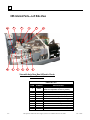
6ES Internal Parts—Left Side View .....................................................................C-2
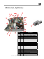
6ES Internal Parts—Right Side View ...................................................................C-3
Spindle Assembly—Exploded View ....................................................................C-4
Appendix D
Statement of Warranty ...................................................................................... D-1
Statement of Warranty ......................................................................................... D-1
Contents
ix
Chapter
Before You Begin
1
Before You Begin
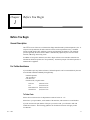
General Description
The 6ES is a state-of-the-art 3-axis Patternless Edger manufactured by National Optronics, Inc. It
will process Polycarbonate, Hi-index and CR-39 lenses with exceptional accuracy. Standard
features include pin beveling, polishing, grooving, and automatic decentration. The clamping
pressure applied by the 6ES’s electric chuck is automatically adjusted by the selection of lens
material, addressing A/R crazing issues.
In addition to its superior mechanics, the 6ES’s unique software can accumulate statistical lens
information that most operators now keep manually. Automatic prompts will remind operators to
maintain their equipment.
For Further Assistance
If you should require any further assistance, National Optronics can be contacted directly between
8:30 AM and 5:00 PM ET Monday through Friday.
National Optronics
100 Avon Street
P.O. Box 1547
Charlottesville, Virginia 22902
Toll-free:
Tel:
Parts Order Fax:
General Fax:
(800) 247-9796
(434) 295-9126
(888) 239-0778
(434) 295-7799
To Order Parts:
Please call our Customer Service Department at 800-247-9796 ext. 317.
Please know your part number, serial number of the machine, and Customer Account Number.
If you do not know the part number of the part you need to order, you will need to talk with
Technical Assistance. The following guidelines for Technical Assistance will apply in that
circumstance.
Rev. 1.082
1-1
1
If you need to return a part, the Customer Service Department will issue a Return Authorization
Number to you and explain the procedure for returning parts.
For Technical Assistance:
Please call our Technical Service Department at 800-247-9796 ext. 314 and know the serial number
of your machine and Customer Account Number. If you purchased your equipment from National
Optronics, there is no charge for telephone support. If, however, you purchased your Optronics
equipment elsewhere, you will be charged for telephone support at the rate of $47.50 per half hour.
If you would like to schedule an on-site Technical Service visit, please call Technical Support at
800-247-9796 ext. 314. Please know the serial number of your machine and Customer Account
Number for requesting a Technical Service visit. There is no charge for warranty service visits. If
your machine is out of warranty, there is a charge of $55.00 per hour for travel to and from the
equipment location and $125.00 per hour (two-hour minimum) for the Technician’s time at the
location. Any additional travel expenses incurred, such as airline tickets, hotel rooms, etc., are
billed to the customer.
The rates published above may be subject to change without notice.
1-2
The Optronics 6ES Patternless Edger System User's Manual – October 20, 2004
Rev. 1.082
1
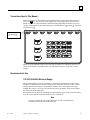
Conventions Used in This Manual
Wherever possible, keys on the 6ES keypad are identified with a graphic representation of the key,
such as, the
key. The function keys run along the top of the keypad and are associated with
buttons on the screen. These buttons have different meanings depending on which screen you are
viewing. Although they are not marked, these keys will be identified as l through s, such as the
Job function key l.
Function keys:
l through s
Names of screens and fields within screens will be placed in Italics, for example, the Setup Screen.
Values in a field will be in quotation marks, as in, The default for the New Code Source field is
“Floppy.”
Requirements for Use
115 VAC 60 Hz 20A Electrical Supply
This is standard outlet power in the United States. The Optronics 6ES Patternless Edger System
should be on a dedicated circuit (no other electrical loads connected to the same circuit) to ensure a
uniform, consistent power supply. The maximum continuous power consumption of the edger,
including the vacuum, is 14.3 amps. The 6ES must be properly grounded—do not use any adapter
that will bypass the grounding plug.
Power fluctuations can adversely affect production and machine integrity. Please contact the factory
if you have power glitches or questions about the power requirements.
Note
The 6ES is available for 230V 50 Hz installations. It is also recommended for
230V units to be installed on a dedicated circuit.
Rev. 1.082
Chapter 1 Before You Begin
1-3
1
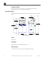
Operating Conditions
The 6ES edger is designed for indoor use only. The edger is designed to operate safely at a
temperature range of 5° C to 40° C, at altitudes up to 2000 meters.
General Specifications
The following drawing illustrates the general specifications of the Optronics 6ES Patternless Edger
System:
General Specifications
Cutters
Coated carbide.
Cutter Motor
Adjustable speed (up to 20,000 RPM) DC Brushless, ¾ Hp.
Bevel Placement
3-Axis Numerical Control; 8 bevel selections with independent point control.
1-4
The Optronics 6ES Patternless Edger System User's Manual – October 20, 2004
Rev. 1.082
1
Vacuum
2.5 HP, 109 CFM (9A).
Lens Materials
CR-39, Polycarbonate, All High Index, Trivex, NO GLASS.
Statement Against Misuse
The 6ES edger is designed to edge plastic lenses only. Any other use of the machine will
compromise its safety protection features.
Caution
The 6ES will edge ONLY PLASTIC LENSES. Under no circumstances
should any attempt be made to process a glass lens on this unit!
Rev. 1.082
Chapter 1 Before You Begin
1-5
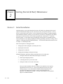
Chapter
Getting Started & Daily Maintenance
2
Section 1: Initial Installation
National Optronics can provide field technicians who will install your equipment and set up the
Optronics 6ES Patternless Edger System to meet the needs of your specific operation. You can,
however, perform these tasks yourself. Use the information in this chapter as a guide through the
initial installation and daily cleaning. To learn about the procedures for changing the cutter blades,
checking size and bevel position, and vacuum bag replacement, read Chapter 3, “Commonly
Performed Tasks.” To learn about tasks performed while using the 6ES in a standard operation,
such as pulling down a job, edging (roughing and finishing), polishing, and safety beveling, refer to
Chapter 4, “Operating the 6ES (Standard Operation).” To learn about calibration instructions, refer
to Chapter 5, “Calibrating the 6ES.”
There are four phases to setting up the 6ES:
1.
Setting up the cabinet (skipped if you already have one)
2.
Preparing the work bench
3.
Setting up the vacuum unit
4.
Setting up the 6ES Edger itself (physical setup)
Within the final phase, physically setting up the 6ES, there are four main steps:
1.
Placing the 6ES on the cabinet and connecting the vacuum unit
2.
Removing the shipping brackets
3.
Connecting the 6ES to your electric outlet
4.
Filling the coolant reservoir (the water bottle)
Note
These procedures should be followed in sequence: the completion of one step may
depend on the one previous to it. Tools are provided in the accessory kit (see the
drawing on page 2- 13) to aid in both the installation and subsequent operation.
The 6ES can be shipped with a cabinet, which is custom designed for the
application. The laboratory can either: (1) use the custom cabinet, or (2) mount the
edger on a standard workbench.
Rev. 1.082
2-1
2
Setting Up the Cabinet
If the edger is being installed on a workbench already present in the lab, proceed to “Preparing the
Workbench” below for making the necessary cutouts.
To set up the Optronics workbench, follow these steps:
1.
Remove the cabinet and cabinet top from the box.
2.
Place cabinet top, white side down, on floor.
3.
Place cabinet upside down on cabinet top, with the doors on the same side as the cutout in the
cabinet top.
4.
Attach cabinet to cabinet top with screws provided.
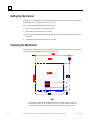
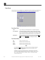
Preparing the Workbench
Prepare the bench surface to be used by cutting an opening for the vacuum hose and vacuum power
cord (if the opening does not already exist) as shown below:
Note
The Optronics cabinet has an additional hole in the back panel, approximately six
inches from the floor, for the vacuum power cord. You may need to cut a hole in
the cabinet or move the cabinet two inches out from the wall to supply power to
2-2
The Optronics 6ES Patternless Edger System User's Manual – October 20, 2004
Rev. 1.082
2
the 6ES itself. The power connection for the 6ES is located on the back of the
unit.
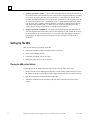
Setting Up the Vacuum Unit
There are two parts to setting up the vacuum unit: assembling the vacuum and setting it up inside the
cabinet.
Assembling the Vacuum
To assemble the vacuum, follow these steps:
1.
Remove the vacuum from the box.
2.
Open the vacuum and remove the accessories from inside the canister.
3.
Install the small motor filter bag, and place the large dust collection bag around the inlet.
4.
Replace the vacuum top, making sure the snaps are tight.
5.
Turn the switch to the ON position—its cycling is controlled automatically.
Setting Up the Vacuum Inside the Cabinet
If you are using a different cabinet than the one Optronics provides, make sure that you have a hole in
the top of the cabinet for the vacuum hose (refer to “Preparing the Workbench” on the previous page).
To set up the vacuum correctly, follow these steps:
Rev. 1.082
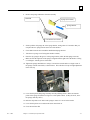
1.
Place the vacuum unit under the workbench so that the short hose can reach from the vacuum
inlet to the underside coupling of the edger chip chute (refer to the left portion of the drawing
shown below).
2.
Run the power cord through the vacuum/power cord hole in the top of the cabinet. After you
have placed the 6ES on the workbench, plug the vacuum power cord into the back of the 6ES
(refer to the right portion of the drawing shown below).
Chapter 2 Getting Started & Daily Maintenance
2-3
2
3.
Properly ground the vacuum: A green, yellow-striped ground wire extends from the can of
the vacuum with an eyelet attached to its end. There are three suggested methods to grounding
the vacuum. In order of preference, these methods are: (1) Attach the eyelet directly to the
ground frame inside the housing of an electrical outlet (preferred) or to the faceplate screw on
the front of the electrical outlet. (2) Attach the eyelet to a grounded metal water pipe. Make
sure the water pipe is grounded, using an ohmmeter to check the continuity between the pipe
and earth ground (grounding rod). (3) Attach the eyelet to the front right bolt of the left
spindle support, running the ground wire up through the chip chute hole.
4.
Properly ground the vacuum hose: The green, yellow-striped ground wire, attached to the
anti-static segment of the vacuum hose, has an eyelet attached to its end. Attach this eyelet to
the same ground as the vacuum itself if the wire will reach. (The three suggested methods to
grounding the vacuum are the same as listed above for the vacuum itself, in that order of
preference.)
Setting Up the 6ES
There are four main steps to setting up the 6ES:
1.
Placing the 6ES on the cabinet and connecting the vacuum unit
2.
Removing the shipping brackets
3.
Connecting the 6ES to your electric outlet
4.
Filling the coolant reservoir (the water bottle)
Placing the 6ES on the Cabinet
To place the 6ES on the cabinet and connect the vacuum correctly, follow these steps:
2-4
1.
Remove the unit from its shipping foam and place it on the cabinet or table with all six feet on
the bench top, and the cutout in the base plate roughly aligned with the cutout in the bench top.
2.
Plug the vacuum power cord into the back of the edger.
3.
Attach the vacuum hose from the bottom of the chip chute to the inlet (lower hole) of the
vacuum.
The Optronics 6ES Patternless Edger System User's Manual – October 20, 2004
Rev. 1.082
2
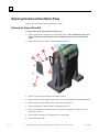
Removing the Shipping Bracket
Remove the shipping brackets and the wire tie marked with the yellow tags (refer to the picture shown
below). The brackets can be removed with a 3/16-inch hex wrench found in the hex key set. Each
item to be removed is identified with a yellow tag.
Connecting the 6ES to an Electric Outlet
As with all electrical equipment, you must ensure proper power connection for proper functionality.
Note
The 6ES Edger must be connected to a dedicated 115V 20A circuit.
Connect the 6ES to power following these steps:
Rev. 1.082
1.
Before connecting power, make sure that the edger ON/OFF switch is “OFF.”
2.
Plug the female end of the power cord into the back of the unit and the male end into the wall
outlet, making sure that the connections are secure.
Chapter 2 Getting Started & Daily Maintenance
2-5
2
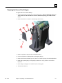
Filling the Coolant Reservoir (the Water Bottle)
The coolant reservoir feeds the coolant to the sponge used for keeping the polishing wheel from
overheating. Ensure that there is always coolant (the mixture of distilled water and Trico’s Tri-Cool
coolant) in the reservoir. Failure to do so may damage the machinery.
To fill the coolant reservoir, follow these steps:
Using the one-ounce measuring cup from the 6ES Accessory Kit, mix one ounce of Trico’s
Tri-Cool coolant with one gallon of distilled water; then fill the reservoir from this mixture.
This ratio of distilled water to Tri-Cool coolant is 128:1.
Note
If the coolant reservoir is totally empty, you may need to “prime the pump”
before it will flow properly. The easiest way to do this is to follow these steps:
1.
Go to the Cleaning Screen (from the Setup Screen, press the Cleaning function
key m).
2.
Move the bevel carriage to the right (non the Cleaning Screen) to gain access to the
solenoid.
3.
Set the Water Flow field to 20.
4.
Down by the solenoid, disconnect the water line running from the pump (to the
solenoid).
5.
Remove the lid of the water bottle.
6.
Hold the water line you just connected so that it will squirt water back in the water
bottle.
7.
Press the Pump on function key pon the Cleaning Screen.
8.
Watch the clear tubes to see if water is coming out—it should be shooting water into
the bottle.
9.
Ensure that the water is flowing properly, then press the Pump off key q.
10. Reconnect the water line to the solenoid.
11. Turn the pump on again and wait for the air to be cleared from the hose leading to the
sponge.
12. Turn the pump off once the air is cleared and the sponge is saturated.
2-6
The Optronics 6ES Patternless Edger System User's Manual – October 20, 2004
Rev. 1.082
2
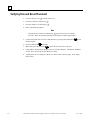
Wetting the Sponge for Initial Use
For the first time you use the 6ES, follow these steps to wet the sponge:
1.
Go to the Cleaning Screen (from the Setup Screen press the Cleaning function key m).
2.
Press the Pump on function key p until the sponge is wet.
3.
Press the Pump off function key q after the sponge is completely wet.
Note
Using a water bottle is an alternative way of wetting the sponge, but the method
described above ensures that the water line is full in addition to wetting the
sponge.
Rev. 1.082
Chapter 2 Getting Started & Daily Maintenance
2-7
2
Powering Up and Calibrating the Probe
Each time you turn on the power switch for the 6ES, you will be prompted to calibrate the probe.
Follow the steps discussed below:
To calibrate the probe:
1.
Locate the black, 58-mm diameter, calibration disc and the Pattern Duplicator Adapter (PDA)
in the accessory kit.
2.
Turn on the power switch.
3.
You will see a message box on the initial 6ES screen stating, “WARNING 101 PLEASE
VERIFY THAT PROBE TIPS ARE PULLED TO THEIR FULL FRONT LIMIT. Mount
probe calibration disk. Press Continue to calibrate probe.” When you see this prompt, chuck
the probe disk (meaning insert the PDA and disk into the Chuck and press the
key to lock
it into place). Also verify that the Probe tips are pointed straight down—see pictures displayed
below.
4.
Press the Continue key l and wait while the probe calibrates itself.
5.
When 6ES is finished calibrating the probe, remove the PDA and disk.
Probe in Correct Position—If the probe tips
are NOT straight down, manually pull them forward
into position.
Probe in Incorrect Position—Note that
the tips are slanted, not straight down.
2-8
The Optronics 6ES Patternless Edger System User's Manual – October 20, 2004
Rev. 1.082
2
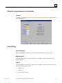
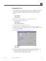
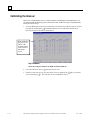
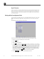
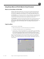
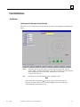
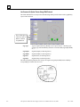
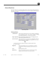
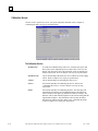
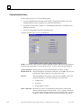
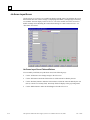
Setting Up Communications for Job Information
Overview
The settings on the Communications Screen are shown in the screen sample below and discussed in
the sections that follow.
Comm Settings
Arcnet Connection
(Optional Equipment) Specifies the type of Arcnet connection (Host, 4T, Saturn, or None).
Machine Node ID
(This field disappears when Arcnet Connection is set to “None.”) Specifies the Node ID of the
Arcnet connection.
Protocol
(This field disappears when Arcnet Connection is set to “None.”) NOP is the protocol being used
for each of the following job sources:
Rev. 1.082
•
A Saturn tracer
•
A 4T tracer
•
A host computer (“Host”)
Chapter 2 Getting Started & Daily Maintenance
2-9
2
Com1 and Com2 Connection
The choices for Com1 and Com2 vary depending on what you have selected in the Arcnet
Connection field. If you have “Host,” “4T,” or “Saturn,”selected for the Arcnet Connection field,
your choice for Com1 (or Com2) is “Barcode” or “None.” If you have “None” selected for the
Arcnet Connection field, your choices include “4T,” “3B” and “Host,” as well as “Barcode” and
“None.” You can only have one Barcode selection.
Baud Rate
(This field only appears when the Com 1 Connection has a Barcode, Host, 3B, or 4T configured.)
This field shows the baud rate for the Com 1 or Com2 Connection. The default is 9600 (or 19,200
if the Protocol is GC). Normally, the 6ES software will supply the correct baud rate automatically.
The edger will not be able to communicate if this parameter is different from the baud rate of the
attached device.
Protocol
(This field only appears when Arcnet Connection is set to “None” and Com1 or Com2 has a 4T or
Host configured.) The choices for Host are OMA or GC; the choice for 4T or 3B is OMA.
OMA Init Level
This field allows you to set the level of OMA initialization to Auto, Preset, or None. Auto is the
best choice most of the time.
Max TRCFMT
This field allows the operator to set the highest trace format used by the 6ES for OMA
communications. This field defaults to 4 for Packed Binary communications. A value of 1 should
be used when communicating with 4Ts earlier than Version 1.23.
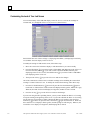
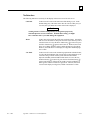
Changing Communications Settings
To change the current communications settings, follow these steps:
1.
From the Setup Screen, press the Advanced Setup function key r.
2.
Press the Communications function key m.
3.
From the Communications Screen, use the Field Down key
to move to the field(s) you
want to change and press the increment
or decrement
keys to change the selection.
(Refer to the field definitions above and on the previous page.)
4.
Enter the password if prompted.
Note
If you receive job numbers using a barcode reader or use a computer connected
through a serial port, use the Communications Screen to set up the COM ports.
2-10
The Optronics 6ES Patternless Edger System User's Manual – October 20, 2004
Rev. 1.082
2
Section 2: Daily Cleaning & Other Daily Maintenance of the 6ES
Daily Cleaning of the 6ES
Keeping the 6ES clean is the largest single component in proper maintenance. Thorough daily
cleanings are strongly recommended and will prevent many service problems and greatly extend
the service life of the edger.
To clean the interior:
1.
Go to the Setup Screen, and select the Cleaning Screen function key m.
2.
Remove the 1½-inch hose from the vacuum canister’s inlet and install the 1½-inch hose fitted
with the crevice tool.
3.
Move the rocker switch on the front left side of the center wall to “CLEAN” position—see
label next to the switch. This will turn on the vacuum, independent of the 6ES’s operation.
4.
Vacuum the debris from the inside of the 6ES with the crevice tool, being careful not to disturb
the control wiring.
5.
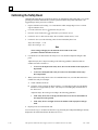
When ready to move on to the next stage of cleaning, press the Size function key m or make
sure the cursor is on the Move Size Carriage option and press the e key to move the size
carriage. Then vacuum the spots you could not reach before.
6.
Then press the Bevel function key n or use the Field Down key
to move the cursor to the
Move Bevel Carriage option and press the e key to move the bevel carriage. Then vacuum
the spots you could not reach before.
7.
Press the Home key o or move the cursor to the Home Carriages option and press the
ekey to move the carriages back to the home position.
8.
Reverse steps 2 and 3 to return the vacuum to normal operation; that is, reconnect the hose and
put the switch back to “CYCLE” position.
9.
Pull the chip chute cover back and clean around the sponge, removing any debris.
10. The exterior may be cleaned with a mild, non-abrasive detergent.
Note
If you bump the probe during cleaning, you should perform the probe calibration
procedure—refer to Chapter 5 for instructions on calibrating the probe.
Rev. 1.082
Chapter 2 Getting Started & Daily Maintenance
2-11
2
Other Daily Maintenance
Checking the Probe Tip for Wear
If excessive wear is present, replace the worn item. Run the probe calibration. Cut a test lens to
verify calibration. For information about calibration, refer to Chapter 5, “Calibrating the 6ES.”
Checking the Clamp Pad
If the pad is torn or loose, replace with a fresh pad. Notice the clamp pad in the picture shown below:
To replace the pad, apply outward pressure to the edge of the pad and pull the old one out. Press
the new one in its place.
2-12
The Optronics 6ES Patternless Edger System User's Manual – October 20, 2004
Rev. 1.082
2
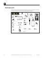
The Accessory Kit
Use the accessories provided to perform setup and other tasks such as daily cleaning. The drawing
shown below identifies the accessories that are usually shipped with the 6ES.
T-15 #6-32 x 3/8" Lg FHCS
P.N. 65232 - (QTY 4)
SYSTEM DISK
P.N. 3319
BACKUP DISK
P.N. 3325
GRAPHICS HELP DISK
P.N. 3322
3/16" LONG HANDLE BALL DRIVER
P.N. 87450
PROBE TIP, TEFLON
P.N. 27092 - (QTY 2)
PATTERN BLANK, RECTANGLE
P.N. 87605 - (QTY 5)
C-BODY SETTING GAUGE
P.N. 87261
3/16" HEX T-HANDLE
P.N. 87452
HUB CLEANING BRUSH
P.N. 87200
6
0
5
4
1
2
3
CLEANING BLOCK
CALL FACTORY FOR
PART NUMBER
9
PATTERN DUPLICATOR
ADAPTOR (PDA)
CALL FACTORY FOR
PART NUMBER
7
15 AMP. FUSE (w/ CONTROLLER)
P.N. 77320
8
INT. SIZE ASS'Y, CLAMP
BODY (RUBBER INSERT)
P.N. 90076 - (STD. LENGTH)
OR
P.N. 90083 (SHORTENED, VARIO BLOCKING)
(QTY 1)
3/32" HEX T-HANDLE
P.N. 87462
MULTIMETER - DIGITAL
P.N. 87410
CALIBRATION DISC
P.N. 87246
WRENCH, 3/16", OPEN END, THIN
P.N. 87227 - (QTY 2)
REPLACEMENT CHIP CHUTE SPONGE
P.N. 28450 - (QTY 2)
CUTTER CLAMP TORX DRIVER
P.N. 87256
NON-CONDUCTIVE
SLOT SCREW DRIVER
P.N. 87445
GROOVING SPROCKET BELT
P.N. 28436 - (QTY 1)
DIAL CALIPER
P.N. 87400
PLASTIC SQUEEZE
WATER BOTTLE
P.N. 75154
MEASURING CUP, 1 OZ
P.N. 85098 - (QTY 1)
INT. SIZE RUBBER INSERT
P.N. 73168 - (QTY 1)
CUTTER, 5mm SHELF (1 PK)
P.N. 93071 - (QTY 1)
PLASTIC BRISTLE BRUSH
P.N. 87201
RUBBER PLUG - TAPERED
P.N. 73166 - (QTY 1)
WHEEL BRUSH, BRASS
P.N. 65411 - (QTY 1)
2-14
HEX KEY SET, BALL TIP, 1/16 - 1/4
(NOT SHOWN)
P.N. 87179 - (QTY 1)
The Optronics 6ES Patternless Edger System User's Manual – October 20, 2004
Rev. 1.082
Chapter
Commonly Performed Tasks
3
To learn about the procedures for changing the cutter blades, checking size and bevel position, and
vacuum bag replacement, read this chapter. For daily operation procedures, refer to Chapter 4.
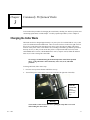
Changing the Cutter Blade
The blade needs to be changed approximately every 300 cycles for a carbide blade or every 3,000
cycles for a diamond-coated carbide blade. There is a Status Indicator in the lower right corner of
the Job Screen (the Status area) that shows how many cycles since the last change. This Status
Indicator turns yellow at 90% of the blade’s life (according to the blade type and life specified on
the Setup Screen), so that you can ensure that you have a replacement blade in stock (Coated
Carbide Blade Part #: 93074, Carbide Blade Part #: 93071; 10-pack: 93072). When the indicator
turns red, it is time to change the cutter blade.
Note
We strongly recommend using the National Optronics cutter blade specified
above. Using alternative cutter blades may cause size, bevel, and finish
problems.
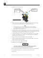
To change the blade, follow these steps:
1. Press the case top release buttons and lift the case top.
2.
Turn off the power switch on the cutter motor controller (far right side of the 6ES).
Turn this
switch OFF
before
proceeding
to the next
step.
Warning
Turn switch to cutter motor OFF before pulling the chip chute cover back
and touching the cutter blade.
Rev. 1.082
3-1
3
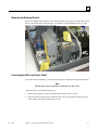
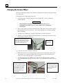
3.
Pull back the plastic chip chute cover.
The two 6-32
flathead Torx
screws
Plastic chip
chute cover
Viewed from Inside Machine
4.
Use the Optronics driver (labeled “Optronics” on the handle) that came in the 6ES accessory
kit to remove the two 6-32 flathead Torx screws holding the clamp in place.
Note
Avoid dropping the two Torx screws down the chip chute into the vacuum bag.
One method of avoiding that would be to stuff a paper towel or rag into the chip
chute opening before removing the screws.
5.
Remove the clamp. If you have trouble getting it to fall out, insert the end of the Torx wrench
into the holes where the screws had been and lift the clamp out. Note that the rounded-off end
is on the right side—you will place it back in the same way in Step 9 below.
6.
Carefully lift the blade out—it may be advisable to wear tight-fitting gloves to avoid cutting
your fingers. Note that the bevel is on the left. (You will need to place the new blade into
place the same way the old one comes out.)
7.
Blow the dust out of the blade and clamp area, then clean with alcohol.
8.
Place the new blade in and slide it to the right (away from the hub) with the right edge of the
blade touching the right edge of the pocket.
9.
Replace the clamp with the rounded-off side on right.
10. Replace the screws while holding the blade in place.
Warning
A new blade is very sharp. Be extremely careful while holding the blade in
place in Step 10 above to avoid cutting your finger on the blade.
11. Release spring loaded chip chute cover and make sure it springs back into its original position.
12. Turn on the motor controller power switch that you turned off in Step 3 above.
13. Close the case.
3-2
The Optronics 6ES Patternless Edger System User's Manual – October 20, 2004
Rev. 1.082
3
Note
If you bump the probe during this process, recalibrate the probe before cutting a
lens—see Chapter 5 for instructions on calibrating the probe.
14. Go to the Log Screen (q from the Advanced Setup Screen).
15. Press the Reset Blade function key n or use the Field Down key
Blade field and press e.
to move to the Reset
16. Type the password if prompted. The blade count resets to zero.
17. Edge a 58 mm circle using internal job 002 to ensure correct calibration. If the lens is not the
correct size, recalibrate the size and bevel as discussed in Chapter 5.
18. Verify polish calibration.
Rev. 1.082
Chapter 3 Commonly Performed Tasks
3-3
3
Changing the Groover Wheel
The Groover wheel (Part Number 93410) needs to be changed when it becomes dull, approximately
every 3000 cycles.
To change the Groover blade, follow these steps:
1. Turn off the motor—make sure the switch on the controller box is “OFF”—THIS IS A
SAFETY ISSUE!
Warning
Ensure that the switch on the controller box is OFF any time you are
touching the cutter blade or groover wheel. Failure to do so could lead to
serious injury.
2.
Place a cloth or plastic bag in the top of the chip chute. Make this a “screw catcher” so that if
you should drop the screw or washer, etc., this cloth will catch the screw instead of it falling
into the chip chute.
3.
Take the two (2) supplied 3/16th-inch open end wrenches out of the accessory kit.
4.
Place one 3/16th-inch open end wrench on the shaft flats (see picture below for location of the
shaft) and place the other on the screw.
The shaft—use one of the 3/16thinch open end wrenches to hold
this while using the other 3/16th
wrench to loosen the screw.
5.
Loosen the screw until it is about to come loose.
6.
Remove the two hex screws securing the plate on the left side of the housing so that you can
access the hex screw within the housing as shown in the picture below. Note that you can
remove two screws and swing it open—see picture below.
7.
To avoid dropping the screw, hold the screw with a pair of needle-nosed pliers to hold the
screw and turn the other end with a 3/32nd hex driver—one is available in the toolkit’s hex tool
cluster.
At this point in the
process, it is better to use a
3/32nd hex driver to loosen
the screw the rest of the
way until the screw with
the washer and groover
wheel disconnects from
the assembly.
3-4
The screw to
be loosened.
The Optronics 6ES Patternless Edger System User's Manual – October 20, 2004
Notice that we have
removed two of the hex
screw holding this plate
(Step 6) so that it can
swing open.
Rev. 1.082
3
8.
Remove the washer and groover wheel from the screw and set the washer and screw aside.
The old groover wheel should be marked as used or thrown away.
9.
Clean debris from around the bearing and shaft before installing the new grooving wheel.
10. Take new groover wheel (P/N 93410) out of the shipping bag.
11. Assemble the screw placing the washer and groover wheel onto the screw in the same manner
as they came off.
12. To avoid dropping the screw, hold the screw with a pair of needle-nosed pliers to hold the
screw and turn the other end with a 3/32nd hex driver—this is the same as done in Step 7 on the
previous page except that you are now tightening instead of loosening.
13. After you have the screw secured in place, you can finish tightening with the two 3/16th-inch
open end wrenches.
Note
There is a small rim on the inside of the shaft flat. Make sure you have the
wheel resting on the small rim prior to final tightening. You will probably
need to lift it slightly to place it on there.
14. Using the two 3/16th-inch open end wrenches, hand tighten the screw until it is very snug.
15. Remove the cloth you placed in the chip chute during Step 2.
16. Turn the motor back on.
17. Go to the Log Screen (q from the Advanced Setup Screen).
18. Press the Reset GBlade function key o or use the Field Down key
Groover field and press e.
to move to the Reset
19. Type the password if prompted. The groover count resets to zero.
20. Recalibrate the groover—refer to Chapter 5 for directions.
Rev. 1.082
Chapter 3 Commonly Performed Tasks
3-5
3
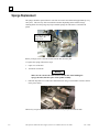
Sponge Replacement
The sponge should be replaced when it wears thin or becomes non-functional (approximately every
300 cycles). This will vary from one machine to another depending on the amount of usage.
Cleaning debris from the sponge may help extend the sponge life and ensure a consistent lens
polish.
Note that the manifold
is attached to the
plastic cover.
Before you begin, retrieve the water bottle from the 6ES Accessory Kit.
To replace the sponge, follow these steps:
1.
Open cover of the 6ES.
2.
Turn motor switch Off.
Warning
Make sure the switch to the cutter motor is turned OFF when handling the
sponge, the hubs, and other parts of the spindle assembly.
3.
Pull back chip chute cover and remove manifold screw using a 7/64-inch hex wrench as shown
in the picture below:
The hex key set (part number 87178) comes in the accessory kit provided with the 6ES.
3-6
The Optronics 6ES Patternless Edger System User's Manual – October 20, 2004
Rev. 1.082
3
4.
Remove the sponge and bracket from the assembly.
Manifold
Sponge (P/N 28450)
Sponge Bracket
7/64-inch hex screw head
5.
Slide or pull the old sponge out of the sponge bracket, noting where it is located so that you
can place the new sponge into the same area of the bracket.
6.
Clean debris from the area around the manifold and sponge bracket.
7.
Take the new sponge out of its bag (Part number: 28450).
8.
Place the dry sponge in the groove in the sponge bracket (where the old sponge came out).
9.
Make sure that the right side of the sponge is aligned with the right side of the bracket. Doing
so will align it with the grooves of the hubs.
10. Tighten the sponge manifold screw using a 7/64-inch hex wrench and wet a single corner of
the sponge with the water bottle, as shown below. This will allow for any left-right adjustment
in the next step.
11. Lower the chip chute and sponge assembly onto the polishing wheels. Make sure that the
points of the sponge fit into the bevel grooves of the polish wheels. (If they do not fit, move
the sponge until they do fit.)
12. Raise the chip chute cover and wet the sponge to ensure it is secure in the bracket.
13. Lower the chip chute cover and turn the cutter motor back on.
14. Close the lid of the 6ES.
Rev. 1.082
Chapter 3 Commonly Performed Tasks
3-7
3
Verifying Size and Bevel Placement
1.
Go to the Setup Screen (s from the Job Screen).
2.
Press the Calibration function key n.
3.
Press the 58mm Circle function key m.
4.
Enter a password if prompted.
Note
Pressing the Size Calibration function key m causes the Job Screen to choose
Job: 002—this is the automatic job setup for checking size and bevel placement.
3-8
5.
Load a 6 base plano lens of at least 2 mm thickness by pressing the Chuck button
the lens in place.
6.
Press the Start button
7.
When done, press the Chuck key
8.
Using calipers, measure from the apex of the bevel to the other apex. The distance should be
58 mm. If it is not exactly 58 mm, adjust Size Offset.
9.
Visually check to see if the apex of the bevel is in the center of the lens edge. If not, adjust
Bevel Offset.
to lock
on the 6ES.
to release the lens; then remove the lens.
The Optronics 6ES Patternless Edger System User's Manual – October 20, 2004
Rev. 1.082
3
Changing the Vacuum Bag
The vacuum bag needs to be changed approximately every 300 cycles. There is a Status Indicator
in the lower right corner of the Job Screen (the Status area—lower right of screen) that graphically
shows how many cycles since the last change. This Status Indicator turns yellow at 90% of the
vacuum bag life, so that you can ensure that you have a replacement bag and filter in stock (Bag
and Filter 5-Pack Set Part # 87142). When it is red, it is time to change the vacuum bag and filter.
This reminder feature can be disabled through the Job Screen Layout field on the Setup Screen.
(Disabling this feature should only be done when using a central vacuum rather than one under the
edger).
Caution
Wear an appropriate dust mask and eye protection when changing the
vacuum bag, especially if you are sensitive to dust particles since the dust is
small particles of plastic.
Change the vacuum bag when it gets full by following these steps:
1. Open the cabinet if applicable.
2.
Make sure the vacuum is turned off.
3.
Disconnect the vacuum hose from the back of the vacuum.
4.
Undo the three clamps holding the top on the vacuum.
5.
Lift the vacuum head out of the vacuum base and set it aside.
6.
Pull the bag back from the inlet fitting.
7.
Lift the large bag out and dispose of it.
8.
Replace it with a new bag. (The bags and filters are often kept in the cabinet—Bag and Filter
5-Pack Set Part # 87142)
9.
Change the paper filter.
A. Examine the top piece that you set aside in Step 5 above. There is a steel ring (some have
a thick rubber band) holding the paper filter onto the foam filter. Squeeze the prongs on
that ring and pull the paper filter off, leaving the foam filter in place.
B. Throw away the paper filter and put another one in its place (within the steel ring).
C. Squeeze hard on the ring’s prongs and slide the filter back into place.
10. Reinstall the vacuum head on the can, aligning the inlet and exhaust holes. Then secure it with
the three clamps.
11. Close the cabinet.
12. Go to the Log Screen (q from the Advanced Setup Screen).
13. Press the Reset Vac function key r or use the
press the e key.
key to move to the Vacuum Bags field and
14. Type the password if prompted. The bag count resets to zero.
Rev. 1.082
Chapter 3 Commonly Performed Tasks
3-9
3
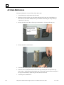
Air Intake Maintenance
For proper maintenance of your air filter, follow these steps:
1.
Turn off the power switch on the side of the 6ES.
2.
Mark the top of the air filter cage with either masking tape, Scotch® tape, Liquid Paper®, or
Wite-Out® (or some other method) so that you will know which side goes on top when you
replace the air filter cage.
3.
Remove the outer part of the air filter cage as shown below. (The cage will snap out.)
Note the white dot
marking the top of
the cage as described
in Step 2.
3-10
4.
Remove the filter as shown below:
5.
Clean the filter with soap and water or replace it with a new filter (Part #: 3069).
6.
Place the new or cleaned filter back in the air filter cage and snap the outer part of the cage
back in place. NOTE: When performing this step, use the mark you placed on the outer part of
the cage to ensure that you replace the piece the same as it came out.
7.
Turn the power switch back on.
The Optronics 6ES Patternless Edger System User's Manual – October 20, 2004
Rev. 1.082
3
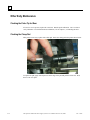
Cleaning the Polishing Wheels
Clean the Polishing Wheels when experiencing poor polish quality and when there is visual
evidence of lens material buildup.
To clean the Polishing Wheels, follow these steps:
1.
Turn the cutter motor off.
2.
Remove the cutter (but not the clamp).
3.
Turn the cutter motor back on.
4.
Remove the Wire Brush and Cleaning Block from the Accessory Kit.
5.
Using calipers or a ruler, check the diameter of the Wire Brush.
6.
Attach the Wire Brush to the Cleaning Block; then chuck the Wire Brush.
7.
Go to the Cleaning Screen (m from the Setup Screen).
8.
On the Cleaning Screen, confirm that the “Brush Diameter” field reflects the actual diameter
of the Wire Brush. If not, type in the correct diameter or use the Up or Down Arrow keys to
adjust the diameter setting.
9.
Press r, the Clean Wheel function, and follow the directions on the screen.
Note
The Wire Brush will make three sweeps across the Polishing Wheel. While it is
making these sweeps, you can adjust the Brush Diameter by pressing the Up
Arrow key to increase or Down Arrow key to decrease the Brush Diameter
setting. When you decrease the Brush Diameter setting, the Size Carriage will
move towards the wheel, which will clean more aggressively.
10. Turn the cutter motor off.
11. Reinstall the cutter.
12. Turn cutter motor back on.
Rev. 1.082
Chapter 3 Commonly Performed Tasks
3-11
3
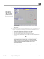
Backing Up the System
National Optronics strongly recommends backing up your system before loading software or make
sure that you have a working backup disk before loading new software. Try to keep that backup
disk up-to-date with the software that is installed on your 6ES.
To backup the 6ES’s software, do the following:
3-12
1.
Go to the Setup Screen—from the Job Screen, press the Setup function key s to select the
Setup Screen.
2.
Press the Advanced Setup Screen function key r to go to the Advanced Setup Screen.
3.
Press the Comm function key mor use the Field Down key
Communications field, then press the ekey.
4.
Press the Backup Sys function key ror use the Field Down key
Backup System button and press the ekey.
5.
Enter the password if prompted. Make sure a blank 3½-inch disk is in the disk drive.
6.
Press the ekey after placing the disk in the disk drive. Follow the screen instructions.
to move the cursor to the
The Optronics 6ES Patternless Edger System User's Manual – October 20, 2004
to move the cursor to the
Rev. 1.082
3
Saving Setup Numbers
National Optronics recommends that you save all calibration and setup numbers (all data saved
across power cycles) to disk for future retrieval with the Restore Setup from Floppy feature prior to
loading new software. It is also a good precaution to perform this task frequently whether or not
you are loading new software. To perform this function, follow these steps:
Rev. 1.082
1.
Insert a 3 ½-inch disk into the 6ES’s disk drive.
2.
Go to the Setup Screen—from the Job Screen, press the Setup function key s to select the
Setup Screen.
3.
Press the Advanced Setup Screen function key r to go to the Advanced Setup Screen.
4.
Press the Comm function key mor use the Field Down key
Communications field, then press the ekey.
5.
Use the Field Down key
ekey.
6.
Enter the password if prompted and make sure your 3 ½-inch disk is in the disk drive.
7.
Press the ekey. Follow the screen instructions.
to move the cursor to the
to move the cursor to the Save Setup Nums button and press the
Chapter 3 Commonly Performed Tasks
3-13
3
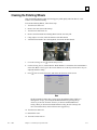
Updating Software
Update to new software using a 3 ½-inch disk through the floppy drive inside the 6ES. National
Optronics strongly recommends that you back up your system—refer to previous page—before
loading software.
To update the 6ES’s software, do the following:
3-14
1.
Go to the Setup Screen—from the Job Screen, press the Setup function key s to select the
Setup Screen.
2.
Press the Advanced Setup Screen function key r to go to the Advanced Setup Screen.
3.
Press the Comm function key mor use the Field Down key
Communications field, then press the ekey.
4.
Backup the System if needed.
5.
Press the Load SW function key qor use the Field Down key
Load Software button and press the ekey.
6.
Enter the password if prompted. If loading from a diskette, make sure it is in the disk drive.
7.
Press the ekey after placing the update disk in the floppy drive. Follow the screen
instructions.
to move the cursor to the
to move the cursor to the
The Optronics 6ES Patternless Edger System User's Manual – October 20, 2004
Rev. 1.082
Chapter
Operating the 6ES (Standard Operation)
4
This chapter includes directions for standard tasks performed while using the 6ES in a standard
operation, such as pulling down a job, edging (roughing, finishing, and grooving), polishing, and
safety beveling. For calibration instructions, refer to Chapter 5.
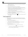
Pulling Down a Job
For standard operations, there are only two steps to this part of the process:
1.
Go to the Job Screen, which is where the 6ES will go automatically if you just started it up.
2.
Type in the number of the job to pull down from a Tracer, Blocker, or Host computer.
Note
Another way of pulling down a job is to scan the job tray with the bar code
reader. (Bar code readers are optional accessories—call National Optronics
technical support if you want information about this.)
The Job Screen parameters can be tailored to meet the specific needs of the user.
Rev. 1.082
4-1
4
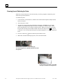
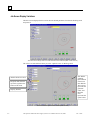
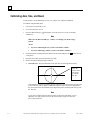
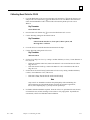
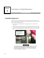
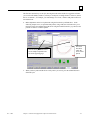
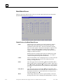
Job Screen Display Variations
The three screens displayed in this section show the default parameters based on the blocking mode
and protocol.
The Job Screen for Single Vision Lens with Geometric Center Selected (OMA or NOP Protocol)
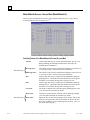
The Job Screen looks different when you select “Optical Center” for Blocking Mode.
Note that the
graphical
representation
of the lens is
also different.
The red cross
represents the
geometric
center, and
the black
cross
represents the
optical center.
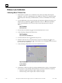
Distance Between Lenses
Height (in mm) from the
top of the segment to the
bottom of the frame
Pupilary Distance
The Job Screen with Optical Center Selected (NOP Protocol)
4-2
The Optronics 6ES Patternless Edger System User's Manual – October 20, 2004
Rev. 1.082
4
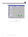
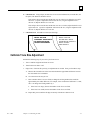
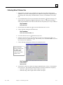
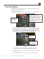
Additional lens blank information is displayed when you use OMA protocol instead of NOP as
shown in the screen shown directly below.
The Job Screen Display with Optical Center Selected (OMA Protocol)
Note
The Job Screen changes based on lens type as well as protocol.
Rev. 1.082
Chapter 4 Operating the 6ES (Standard Operation)
4-3
4
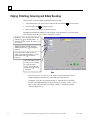
Edging, Polishing, Grooving and Safety Beveling
The basic steps involved in edging, polishing and safety beveling:
1.
After pulling down a job, put the lens in and press the Chuck button
2.
Press the Start button
3.
Wait until the process finishes and remove the lens.
to lock it in place.
to begin the process.
Depending on the materials and the job, there might be a few adjustments. The picture shown
below illustrates the fields you would be most likely to modify:
Modify the Frame field (press the Frame
function key m) if changing frame. To
perform grooving, choose “St. Groove” or
“W. Groove.”
Modify the Material field (press the
Material function key n) if changing
material.
Check this field to polish the lens or
uncheck it to skip the polishing—use the
Polish function key p to check or
uncheck.
Check this field to create
a safety bevel or uncheck
it to skip the safety
bevel—use the SBevel
function key q to check
or uncheck.
Note
If the Frame type is “St. Groove” or “W. Groove” and you have the Grooving
spindle arrangement, then the cycle will include grooving of the lens.
In addition, if you place an exclamation point (!) within the name of the frame,
the 6ES will include standard grooving for the job (for example, “metal!”). If you
place a # sign within the name (for example, “plastic#”), the 6ES will include
wide grooving for the job.
4-4
The Optronics 6ES Patternless Edger System User's Manual – October 20, 2004
Rev. 1.082
Chapter
Calibrating the 6ES
5
The 6ES arrives from the factory already tuned and calibrated and ready to go into production
immediately. You should check the calibration occasionally, and adjust it if necessary. The table
shown below indicates times when calibration should be checked.
Calibrate:
Axis
Probe
Bevel
Size
Rimless
Polish
Size
Safety
Groove Depth
Bevel
& Placement
Change:
Cutter Insert
*
*
*
Cutter Assembly
*
*
*
*
*
Probe Tips
*
*
*
Probe Assembly
*
*
*
*
*
Axis Home Switch
*
Bevel Home Switch
*
Size Home Switch
*
Grooving Blade
*
*
*
*
*
The following procedures should be followed in order to properly calibrate the 6ES. It is very
important to proceed in order, as one step may require previous steps to be completed properly.
Also, note that Probe Calibration is part of the power-up process; for more information, refer
to the steps detailed on the following page.
Rev. 1.082
5-1
5
Calibrating the Probe
Each time you turn on the power switch for the 6ES, you will be prompted to calibrate the probe.
Follow the prompts.
If you wish to calibrate the probe after bootup, before performing other calibration, follow the
following steps.
To calibrate the probe:
1.
Locate the black, 58-mm diameter, calibration disk and the Pattern Duplicator Adapter (PDA)
in the accessory kit.
2.
Go to the Calibration Screen.
3.
Press the Probe button q on the Calibration Screen.
4.
You will see a message box on the initial 6ES screen stating, “WARNING 101 PLEASE
VERIFY THAT PROBE TIPS ARE PULLED TO THEIR FULL FRONT LIMIT. Mount
probe calibration disk. Press Continue to calibrate probe.” When you see this prompt, chuck
the probe disk (meaning insert the disk and PDA into the Chuck and press the
button to
lock it into place). Also, verify that the Probe tips are in the correct position—see pictures
shown below.
5.
Press the e key and wait while the probe calibrates itself.
6.
When the 6ES is finished calibrating the probe, remove the PDA and disk.
Probe in Correct Position—Note that the tips
are straight down, not slanted as shown below.
Probe in Incorrect Position—Note that
the tips are slanted, not straight down.
5-2
The Optronics 6ES Patternless Edger System User's Manual – October 20, 2004
Rev. 1.082
5
Calibration: Overview
There are several ways of calibrating the 6ES: cutting an SBA (Size/Bevel/Axis) shape, cutting a
circle, cutting an aviator, and cutting a grooved circle. Each has its own advantages and
disadvantages:
•
Use the SBA shape (with pattern) to calibrate everything needed for edging calibration,
specifically size (both bevel and rimless), axis, and bevel placement.
•
It is strongly recommended to use the circle for polish and groover calibration. It can also be
used for size and bevel calibration (but not axis).
•
Use the aviator shape to calibrate the safety bevel.
•
Use the grooved circle to calibrate groove placement and depth.
Read this chapter to learn the steps involved in each of the types of calibration.
Rev. 1.082
Chapter 5 Calibrating the 6ES
5-3
5
Calibrating Axis, Size, and Bevel
As stated earlier, use the SBA shape for axis, size, rimless size, and bevel calibration.
To calibrate using the SBA shape:
1.
Get a pattern out and ready to use.
2.
Go to the Calibration Screen.
3.
Press the SBA function key n which takes you to the Job Screen (set up for an SBA
calibration).
Note
Make sure the Material field says, “CR39,” even though you will be using a
pattern.
ALSO:
•
If you are calibrating the size, set the Frame field to “Metal.”
•
If you are calibrating a rimless, set the Frame field to “Rimless.”
4.
Chuck the pattern (meaning insert the pattern into the Chuck and press the
it into place).
5.
Press the Start button, then wait until the cycle ends.
6.
Remove the pattern and physically examine it:
button to lock
A. Check the axis. The point should be on the 180° line (see drawing shown below).
Check the
point to make
sure it lines
up with the
180° line.
If the point does not line up with the 180° line, adjust the Axis Offset and recut. If the point
is above the line, make a negative adjustment to the Axis Offset (a positive adjustment if
the point is below the line) and then recut. Repeat the process until the point lines up with
the 180° line.
Note
If you prefer to think of moving the line relative to the point of the SBA, you can
adjust the Axis Offset positive to move the line clockwise, negative to move the
line counter-clockwise.
5-4
The Optronics 6ES Patternless Edger System User's Manual – October 20, 2004
Rev. 1.082
5
B. Check the size. Using calipers, measure the size across the B dimension (on round sides, not
the point). The diameter should be 58 mm.
If the calipers do not read 58 mm and the lens was cut with a bevel, adjust the Size Offset
and recut. (A positive adjustment will increase the size; a negative adjustment will
decrease it.) Repeat until the size is 58 mm.
If the calipers do not read 58 mm and the lens was cut as a rimless, adjust the Rimless Size
Offset and recut. (A positive adjustment will increase the size; a negative adjustment will
decrease it.) Repeat until the size is 58 mm.
C. Check the bevel. It should be centered (see drawing).
BEVEL TOO FAR
FORWARD - MOVE BACK
BY NEGATIVE BEVEL
OFFSET ADJUSTMENT
BEVEL TOO FAR
BACKWARD - MOVE
FORWARD BY POSITIVE
BEVEL OFFSET
ADJUSTMENT
Calibrate Trace Size Adjustment
Perform the following steps if you receive jobs from a tracer.
1.
Trace a medium weight metal frame on a tracer.
2.
Transfer the trace data to a 6E.
3.
Edge a lens. If the lens fits precisely, no adjustments are needed. If not, perform these steps:
A. Measure the circumference of the lens and calculate the approximate difference between
the lens and the size it should be.
B. Go to the Advanced Setup Screen.
C. Enter a number in the Trace Size field (or change the existing number) that would be
approximately the radius difference; for example, if the circumference difference is 3 mm,
enter 1 or change the existing number by 1.
•
If the lens is too large, decrease the number in the Trace Size field.
•
If the lens is too small, increase the number in the Trace Size field.
D. Repeat this process until the 6E edges accurately with the trace data received.
Rev. 1.082
Chapter 5 Calibrating the 6ES
5-5
5
Calibrating the Polishing Wheels
The following pages provide a step-by-step process for calibrating the polish wheels. When you are
more familiar with the 6ES screens and terminology, you may wish to refer to the “6ES Polish
Calibration Quick Reference Guide” section on Page 5-24.
During the process of calibrating the polishing wheels, it is very important that the following steps
be performed in order, and that each step is completed before moving on to the next step.
Wheel 2 (CR-39, High
Index)
Wheel 1
(Poly, Trivex)
NOP Cutter (Dry
Rough & Bevel All
Materials)
Note
CR-39 and High Index are polished wet on Wheel 2 only. The best finish for
Poly and Trivex requires polishing dry first, then wet on Wheel 1. The directions
provided on the following pages assume that you are calibrating both wheels and
that you begin with Wheel 1.
5-6
The Optronics 6ES Patternless Edger System User's Manual – October 20, 2004
Rev. 1.082
5
Calibrating Wheel 1
Calibrating Wheel 1 Bevel
1.
Ensure that the “dry blade” size is calibrated correctly before proceeding with the polish
calibration—refer to the “Calibrating Axis, Size, and Bevel” on Page 5-4, or edge the internal
58 mm shape (Job # 002) using a medium thickness, 6.0 base, 75-mm diameter or less, Poly
lens.
2.
Go to the Blank Material Screen (press the Materials function key o from the Setup Screen)
and press the Poly function key non the Blank Material Screen. Ensure that Polish has a
check mark and that Wheel 1W is selected. This will cause the polish cycle to be wet on
Wheel 1.
Key Parameter:
Poly Wheel=1W
3.
Press the Material2 function key s to access the Blank Materials 2 Screen.
4.
Use the following settings for the material Poly:
Key Parameters:
Poly Takeoff=0.00 and Revs=2
5.
Go to the Calibration Screen (n from the Setup Screen).
6.
From the Calibration Screen, move the cursor to 58 mm Circle and press the ekey (or
press the 58 mm Circle function key m). This will take you to a modified Job Screen (one set
up for 58 mm circle calibration).
7.
Use the following settings on the 58 mm Circle Calibration Screen:
Key Parameter:
Material=Poly
Rev. 1.082
Chapter 5 Calibrating the 6ES
5-7
5
8.
Set the Wheel 1 Bevel Offset by cutting a medium thickness, 6.0 base, 75-mm diameter or less,
Poly lens. The polishing wheel should lightly touch both the front and the back of the bevel.
•
•
•
•
•
If just the back is polished, enter a negative Wheel 1 Bevel Offset.
If just the front is polished, enter a positive Wheel 1 Bevel Offset.
If the lens is not polished, enter a negative Wheel 1 Size Offset.
If the lens is completely polished, enter a positive Wheel 1 Size Offset.
Repeat as necessary until both sides of bevel are lightly touched. Try adjusting in 0.05 mm
increments.
Note
To conserve lenses, the test cuts can initially be oversized, and then decreased by
3 mm per iteration. For example, by setting the Box Size to +6.00 for the first
cut, it can then be edged at +3 mm, then +0.00, -3.00, and finally –6.00 mm,
resulting in 5 test cuts per lens. Once adjustments are close enough that the lens
touches the Polishing Wheel, do not use re-cut mode—this will result in
inaccurate bevel placement.
If you use Circ Size, instead of Box Size, you can accomplish the same thing by
downsizing the Circ Size by –10.00 mm each time.
In addition, please note that setting the Offset is a quick and easy way of
adjusting the bias. When you enter an Offset, the 6ES automatically adjusts the
bias numbers on the Advanced Setup Screen. If this is changed on the
Calibration Screen, when you return to this screen later, you will see that the
Offset is zero (0) rather than the number you have entered. That shows that it has
made the adjustment on the bias numbers—the bias numbers will change by the
amount (positive or negative) that you enter in the Offset. If you change this on
the Job Screen (the special one set up for 58 mm circle calibration), the Offset
will change to zero when you press the Start button. Alternatively, you can press
the Advanced Setup function key s and modify the Bias numbers directly.
5-8
The Optronics 6ES Patternless Edger System User's Manual – October 20, 2004
Rev. 1.082
5
Calibrating Wheel 1 Size
9.
Go to the Blank Material Screen (press the Materials function key o from the Setup Screen)
and press the Poly function key non the Blank Material Screen. Ensure that Polish has a
check mark and that Wheel 1D is selected. This will cause the polish cycle to be dry on
Wheel 1.
Key Parameters:
Poly Wheel=1D
10. Press the Material2 function key s to access the Blank Materials 2 Screen.
11. Use the following settings for the material Poly:
Key Parameters:
Poly Takeoff=0.30 and Revs=2
12. Go to the Calibration Screen (n from the Setup Screen).
13. From the Calibration Screen, move the cursor to 58 mm Circle and press the ekey (or
press the 58 mm Circle function key m). This will take you to a modified Job Screen (one set
up for 58 mm circle calibration).
14. Use the following setting on the 58 mm Circle Calibration Screen:
Key Parameter:
Material=Poly
15. Set the Wheel 1 Size Offset by cutting a medium thickness, 6.0 base, 75-mm diameter or less,
Poly lens. The polishing wheel should remove material around the lens completely.
•
•
Rev. 1.082
If the lens is small, enter a positive Wheel 1 Size Offset.
If the lens is large, enter a negative Wheel 1 Size Offset.
Chapter 5 Calibrating the 6ES
5-9
5
Calibrating Wheel 2
Calibrating Wheel 2 Bevel
1.
Ensure that the “dry blade” size is calibrated correctly before proceeding with the polish
calibration—refer to the “Calibrating Axis, Size, and Bevel” on Page 5-4, or edge the internal
58 mm shape (Job # 002) using a medium thickness, 6.0 base, 75-mm diameter or less, Poly
lens.
2.
Go to the Blank Material Screen (press the Materials function key o from the Setup Screen)
and press the Poly function key mon the Blank Material Screen. Ensure that Polish has a
check mark and that Wheel 2W is selected. This will cause the polish cycle to be wet on
Wheel 2.
Key Parameters:
Poly Wheel=2W
3.
Press the Material2 function key s to access the Blank Materials 2 Screen.
4.
Use the following settings for the material Poly:
Key Parameters:
Poly Takeoff=0.00 and Revs=2
5-10
5.
Go to the Calibration Screen (n from the Setup Screen).
6.
From the Calibration Screen, move the cursor to 58 mm Circle and press the ekey (or
press the 58 mm Circle function key m). This will take you to a modified Job Screen (one set
up for 58 mm circle calibration).
The Optronics 6ES Patternless Edger System User's Manual – October 20, 2004
Rev. 1.082
5
7.
Use the following settings on the 58 mm Circle Calibration Screen:
When calibrating
Wheel 2 Bevel, use
“Poly” as the material
with the values shown
in this sample screen.
Key Parameters:
Material=Poly
8.
Set the Wheel 2 Bevel Offset by cutting a medium thickness, 6.0 base, 75-mm diameter or less,
Poly lens. The polishing wheel should lightly touch both the front and the back of the bevel.
•
•
•
•
•
If just the back is polished, enter a negative Wheel 2 Bevel Offset.
If just the front is polished, enter a positive Wheel 2 Bevel Offset.
If the lens is not polished, enter a negative Wheel 2 Size Offset.
If the lens is completely polished, enter a positive Wheel 2 Size Offset.
Repeat as necessary until both sides of bevel are lightly touched. Try adjusting in 0.05 mm
increments.
Note
To conserve lenses, the test cuts can initially be oversized, and then decreased by
3 mm per iteration. For example, by setting the Box Size to +6.00 for the first
cut, it can then be edged at +3 mm, then +0.00, –3.00, and finally –6.00 mm,
resulting in 5 test cuts per lens. Once adjustments are close enough that the lens
touches the Polishing Wheel, do not use re-cut mode—this will result in
inaccurate bevel placement.
If you use Circ Size, instead of Box Size, you can accomplish the same thing by
downsizing the Circ Size by –10.00 mm each time.
Rev. 1.082
Chapter 5 Calibrating the 6ES
5-11
5
Calibrating Wheel 2 Size
9.
Go to the Blank Material Screen (press the Materials function key o from the Setup Screen)
and press the Poly function key mon the Blank Material Screen. Ensure that Polish has a
check mark and that Wheel 2D is selected. This will cause the cycle to be dry on Wheel 2.
Key Parameter:
Poly Wheel=2D
10. Press the Material2 function key s to access the Blank Materials 2 Screen.
11. Use the following settings for the material Poly:
Key Parameters:
Poly Takeoff=0.30 and Revs=2
12. Go to the Calibration Screen (n from the Setup Screen).
13. From the Calibration Screen, move the cursor to 58 mm Circle and press the ekey (or
press the 58 mm Circle function key m). This will take you to a modified Job Screen (one set
up for 58 mm circle calibration).
14. Use the following settings on the 58 mm Circle Calibration Screen:
When calibrating
Wheel 2 Size, use
“Poly” as the material
with the values shown
in this sample screen.
Key Parameters:
Material=Poly
15. Set the Wheel 2 Size Offset by cutting a medium thickness, 6.0 base, 75-mm diameter or less,
Poly lens. The polishing wheel should remove material around the lens completely.
5-12
•
If the lens is small, enter a positive Wheel 2 Size Offset.
•
If the lens is large, enter a negative Wheel 2 Size Offset.
The Optronics 6ES Patternless Edger System User's Manual – October 20, 2004
Rev. 1.082
5
Calibrating Poly Bevel Polish
1.
Go to the Blank Material Screen (press the Materials function key o from the Setup Screen)
and press the Poly function key non the Blank Material Screen. Ensure that Polish has a
check mark and that Wheel 1D-1W is selected. This will invoke a polish cycle on Wheel 1 that
is first dry and then wet.
Key Parameter:
Poly Wheel=1D-1W
2.
Press the Material2 function key s to access the Blank Materials 2 Screen.
3.
Use the following settings for the material Poly:
Key Parameters:
The Dry Cycle key parameters are:
Takeoff=0.30, Revs=2, Lens rpm=10, Motor RPM=7
The Wet Cycle parameters are:
Takeoff=0.02, Revs=4, Lens rpm=10, Motor RPM=10, and
Bev Edge Pres.= 0.10 mm
4.
Go to the Calibration Screen (n from the Setup Screen).
5.
From the Calibration Screen, move the cursor to 58 mm Circle and press the ekey (or
press the 58 mm Circle function key m). This will take you to a modified Job Screen (one set
up for 58 mm circle calibration).
6.
Use the following settings on the 58 mm Circle Calibration Screen:
When calibrating Poly
Bevel Polish, use the
values shown in this
sample screen.
Key Parameter:
Material=Poly
Rev. 1.082
Chapter 5 Calibrating the 6ES
5-13
5
7.
Set the Poly Edge Bev Pres. by cutting a medium thickness, 6.0 base, 75-mm diameter or less,
Poly lens.
•
•
8.
5-14
If there are striations on the lens, return to the Materials 2 Screen and increase the Poly
Edge Bev Pres.
If the lens material “balls up,” return to the Materials 2 Screen and decrease the Poly Edge
Bev Pres.
No further calibration should be required. From the Job Screen, pull down Job 002 (58 mm)
or internal Job 001 (Aviator) and edge a Poly lens to verify edge polish. If problems are
encountered, refer back to individual wheel calibration.
The Optronics 6ES Patternless Edger System User's Manual – October 20, 2004
Rev. 1.082
5
Calibrating Bevel Polish for CR-39
1.
Go to the Blank Material Screen (press the Materials function key o from the Setup Screen)
and press the CR-39 function key mon the Blank Material Screen. Ensure that Polish has a
check mark and that Wheel 2W is selected. This will cause the polish cycle to be wet on
Wheel 2.
Key Parameter:
CR-39 Wheel=2W
2.
Press the Material2 function key s to access the Blank Materials 2 Screen.
3.
Use the following settings for the material CR-39:
Key Parameters:
CR-39 Takeoff=0.10, Rev=4, Lens rpm=7, Motor rpm=6, and
Bev Edge Pres.= 0.10 mm
4.
Go to the Job Screen and call down the internal 002 circle shape.
5.
Use the following setting on the Job Screen:
Key Parameter:
Material=CR-39
6.
Set the CR-39 Edge Bev Pres. by cutting a medium thickness, 6.0 base, 75-mm diameter or
less, Poly lens.
•
•
7.
If there are striations on the lens, return to the Materials 2 Screen and increase the CR-39
Edge Bev Pres.
If the lens material “balls up,” return to the Materials 2 Screen and decrease the CR-39
Edge Bev Pres.
Set the CR-39 Wet Polish Takeoff (on the Material2 Screen) by cutting a medium thickness,
6.0 base, 75-mm diameter or less, CR-39 lens.
•
•
If the lens is large, decrease the CR-39 Wet Polish Takeoff.
If the lens is small, increase the CR-39 Wet Polish Takeoff.
Note
Steps 6 and 7 are intended to maximize the polish quality while maintaining size.
These parameters are interrelated and may work best in an iterative application;
that is, after completing Step 7, you may need to repeat Step 6.
8.
Rev. 1.082
No further calibration should be required. From the Job Screen, pull down Job 002 (58 mm)
or internal Job 001 (Aviator) and edge a CR-39 lens to verify edge polish. If problems are
encountered, refer back to individual wheel calibration.
Chapter 5 Calibrating the 6ES
5-15
5
Rimless Lens Calibration
Calibrating Wheel 1 Rimless Size
1.
Ensure that the “dry blade” size is calibrated correctly before proceeding with the polish
calibration—refer to the “Calibrating Axis, Size, and Bevel” on Page 5-4, or edge the internal
58 mm shape (Job # 002) using a medium thickness, 6.0 base, 75-mm diameter or less, Poly
lens.
2.
Go to the Blank Material Screen (press the Materials function key o from the Setup Screen)
and press the Poly function key non the Blank Material Screen. Ensure that Polish has a
check mark and that Wheel 1D is selected. This will cause the polish cycle to be dry on
Wheel 1.
Key Parameter:
Poly Wheel=1D
3.
Press the Material2 function key s to access the Blank Materials 2 Screen.
4.
Use the following settings for the material Poly:
Key Parameters:
Poly Takeoff=0.30 and Revs=2
5.
Go to the Calibration Screen (n from the Setup Screen).
6.
From the Calibration Screen, move the cursor to 58 mm Circle and press the ekey (or
press the 58 mm Circle function key m). This will take you to a modified Job Screen (one set
up for 58 mm circle calibration).
7.
Use the following settings on the 58 mm Circle Calibration Screen:
Key Parameters:
Frame=Rimless
Material=Poly
8.
Set the Wheel 1 Rimless Size Offset by cutting a medium thickness, 6.0 base, 75-mm diameter
or less, Poly lens. The polishing wheel should remove material around the lens completely.
•
•
5-16
If the lens is small, enter a positive Wheel 1 Rimless Size Offset.
If the lens is large, enter a negative Wheel 1 Rimless Size Offset.
The Optronics 6ES Patternless Edger System User's Manual – October 20, 2004
Rev. 1.082
5
Calibrating Wheel 2 Rimless Size
1.
Ensure that the “dry blade” size is calibrated correctly before proceeding with the polish
calibration—refer to the “Calibrating Axis, Size, and Bevel” on Page 5-4, or edge the internal
58 mm shape (Job # 002) using a medium thickness, 6.0 base, 75-mm diameter or less, Poly
lens.
2.
Go to the Blank Material Screen (press the Materials function key o from the Setup Screen)
and press the Poly function key mon the Blank Material Screen. Ensure that Polish has a
check mark and that Wheel 2D is selected. This will cause the polish cycle to be dry on Wheel 2.
Key Parameter:
Poly Wheel=2D
3.
Press the Material2 function key s to access the Blank Materials 2 Screen.
4.
Use the following settings for the material Poly:
Key Parameters:
Poly Takeoff=0.10 and Revs=2
5.
Go to the Calibration Screen (n from the Setup Screen).
6.
From the Calibration Screen, move the cursor to 58 mm Circle and press the ekey (or
press the 58 mm Circle function key m). This will take you to a modified Job Screen (one set
up for 58 mm circle calibration).
7.
Use the following setting on the 58 mm Circle Calibration Screen:
When calibrating
Wheel 2 Rimless Size,
use “Poly” as the
material with the
values shown in this
sample screen.
Key Parameters:
Frame=Rimless
Material=Poly
8.
Set the Wheel 2 Rimless Size Offset by cutting a medium thickness, 6.0 base, 75-mm diameter
or less, Poly lens. The polishing wheel should remove material around the lens completely.
•
•
Rev. 1.082
If the lens is small, enter a positive Wheel 2 Rimless Size Offset.
If the lens is large, enter a negative Wheel 2 Rimless Size Offset.
Chapter 5 Calibrating the 6ES
5-17
5
Calibrating Poly Rimless Polish
1.
Go to the Blank Material Screen (press the Materials function key o from the Setup Screen)
and press the Poly function key non the Blank Material Screen. Ensure that Polish has a
check mark and that Wheel 1D-1W is selected. This will invoke a polish cycle on Wheel 1 that
is first dry and then wet.
Key Parameter:
Poly Wheel=1D-1W
2.
Press the Material2 function key s to access the Blank Materials 2 Screen.
3.
Use the following settings for the material Poly:
Key Parameters:
Dry Polishing: TO = 0.30, revs = 2, Lens rpm = 10, Motor rpm = 7
Wet Polishing: TO = 0.02, revs = 4, Lens rpm = 10, Motor rpm = 10, and
Rmls Bev Edge Pres.= 0.10 mm
4.
Go to the Calibration Screen (n from the Setup Screen).
5.
From the Calibration Screen, move the cursor to 58 mm Circle and press the ekey (or
press the 58 mm Circle function key m). This will take you to a modified Job Screen (one set
up for 58 mm circle calibration).
6.
Use the following setting on the 58 mm Circle Calibration Screen:
Key Parameters:
Frame=Rimless
Material=Poly
7.
Set the Rmls Bev Edge Pres. by cutting a medium thickness, 6.0 base, 75-mm diameter or less,
Poly lens.
•
•
5-18
If there are striations on the lens, increase Wheel 2 Rmls Bev Edge Pres.
If the lens material “balls up,” decrease Wheel 2 Rmls Bev Edge Pres.
The Optronics 6ES Patternless Edger System User's Manual – October 20, 2004
Rev. 1.082
5
8.
No further calibration should be required. From the Job Screen, pull down Job 002 (58 mm)
or internal Job 001 (Aviator) and edge a Poly lens to verify edge polish. If problems are
encountered, refer back to individual wheel calibration.
Calibrating CR-39 Rimless Polish
1.
Ensure that Wheel 1 and Wheel 2 have been calibrated according to the previous steps.
2.
Go to the Blank Material Screen (press the Materials function key o from the Setup Screen)
and press the CR-39 function key mon the Blank Material Screen. Ensure that Polish has a
check mark and that Wheel 2W is selected. This will cause the polish cycle to be wet on
Wheel 2.
Key Parameter:
CR-39 Wheel=2W
3.
Press the Material2 function key s to access the Blank Materials 2 Screen.
4.
Use the following settings for the material CR-39:
Key Parameters:
CR-39 Takeoff=0.10, Revs=4, Lens rpm=7, Motor rpm=6, and Rmls Bev
Edge Pres.=0.10 mm
5. Go to the Job Screen and call down the internal 002 circle shape.
6.
Use the following setting on the Job Screen:
Key Parameter:
Material=CR-39
7.
Set the Rmls Bev Edge Pres. by cutting a medium thickness, 6.0 base, 75-mm diameter or less,
CR-39 lens.
•
•
8.
If there are striations on the lens, increase Wheel 2 Rmls Bev Edge Pres.
If the lens material “balls up,” decrease Wheel 2 Rmls Bev Edge Pres.
Set the CR-39 Wet Polish Takeoff (on the Material2 Screen) by cutting a medium thickness,
6.0 base, 75-mm diameter or less, CR-39 lens.
•
•
If the lens is large, decrease the CR-39 Wet Polish Takeoff.
If the lens is small, increase the CR-39 Wet Polish Takeoff.
Note
Steps 7 and 8 are intended to maximize the polish quality while maintaining size.
These parameters are interrelated and may work best in an iterative application;
that is, after completing Step 7, you may need to repeat Step 6.
9.
Rev. 1.082
No further calibration should be required. From the Job Screen, pull down Job 002 (58 mm)
or internal Job 001 (Aviator) and edge a Poly lens to verify edge polish. If problems are
encountered, refer back to individual wheel calibration.
Chapter 5 Calibrating the 6ES
5-19
5
Calibrating the Safety Bevel
Calibrating the Safety Bevel is generally the last step in calibrating the 6ES polish; that is, you would
generally perform this calibration after you have performed all the other polish calibrations. The
suggested steps for the process are as follows:
1.
Prepare a blank lens for cutting. Use a lens that has a thick enough edge to leave a 4-5mm
edge on a Rimless Lens.
2.
Go to the Calibration Screen (n from the Setup Screen).
3.
Press the Aviator function key o, which takes you to the Job Screen.
4.
On the Job Screen, make sure the Safety Bevel field has a check mark (9) in it.
5.
On the Job Screen, use the following values for the initial Safety Bevel cut:
Safety Bevel Depth: +1.00
Safety Bevel Margin: 0.0
Note
These settings will apply for the material selected and are the same
parameters found on the Material Screen.
6.
Cut a Rimless Lens and examine the safety bevel. You should not adjust the margin at this
point.
Adjust the Safety Bevel Depth according to the following guidelines (and afterwards cut
another lens and re-examine it):
7.
•
To increase the depth of the safety bevel, increase the number in the Safety Bevel
Depth field.
•
To decrease the depth of the safety bevel, decrease the number in the Safety
Bevel Depth field.
When you have the Safety Bevel correct for a thick Rimless Lens, cut a thin Beveled Lens to
calibrate the safety bevel margin:
A. Chuck a thin Beveled Lens.
B. Using the Aviator selection as discussed above, cut a lens that will have an edge thinner
than the bevel (approximately 3mm). The safety bevel should lightly touch the back of
the frame bevel.
Adjust the Safety Bevel Margin according to the following guidelines:
8.
•
If the safety bevel cuts too deeply into the frame bevel, increase the number in
the Safety Bevel Margin field.
•
If the safety bevel is too light, decrease the number in the Safety Bevel Margin
field.
Repeat process for each material used.
You can use the Copy to All Materials button to copy the Safety Bevel Depth and Margin currently
displayed to all materials defined on the Materials Screen.
5-20
The Optronics 6ES Patternless Edger System User's Manual – October 20, 2004
Rev. 1.082
5
Adjusting the Water Flow
If you have cut a couple of lenses and the water flow does not seem correct (too much flow or not
enough), you can adjust the water flow by following these steps:
1.
Go to the Blank Materials Screen (from the Setup Screen press the Material function key o).
2.
Move the cursor to the material you are using; then move the cursor to the Water Flow field.
3.
Increase the value in this field to increase the water flow; decrease it to decrease the water
flow. Enter a password if prompted.
4.
Test the water flow by running another cycle. If the water flow is still not adjusted correctly,
readjust the flow. See Note below for an alternative way of testing.
Note
You can also test the water flow on the Cleaning Screen. The numbers on the
Water Flow field there directly correspond to the numbers on the Blank Materials
Screen.
Rev. 1.082
Chapter 5 Calibrating the 6ES
5-21
5
Calibrating the Groover
The process of calibrating the Groover is almost identical to calibrating the Polishing Wheels. It is
very important that the following steps be performed in order, and that each step is completed before
moving on to the next step.
1.
Go to the Blank Material Screen (press the Materials function key from the Setup Screen) and
press the CR-39 function key mon the Blank Material Screen and ensure that the CR-39
grooving settings are the same as shown below:
When calibrating
the groover, use
CR-39 as the
material with the
values shown in
this sample
screen.
Key Parameters:
CR-39 Grooving Feed=0.02, Lens RPM=10, Motor RPM=10
5-22
2.
Go to the Calibration Screen (n from the Setup Screen).
3.
From the Calibration Screen, move the cursor to Groove and press the ekey (or press the
Groove function key p). This will take you to a modified Job Screen.
The Optronics 6ES Patternless Edger System User's Manual – October 20, 2004
Rev. 1.082
5
4.
Use the following setting on the Groove Calibration Screen:
Key Parameters:
Size=0, Frame=St. Groove, Material=CR-39, Bevel=Center, Polish=No, and
Safety Bevel=No
5.
Set the Standard Groove Placement by cutting a 3-5 mm finished edge thickness CR-39 lens.
The groove should be centered on the lens.
•
•
If the groove is too far forward, use a negative number to adjust the Standard Placement.
If the groove is too far backward, use a positive number to adjust the Standard Placement
Note
To conserve lenses, the test cuts can initially be oversized, and then decreased by
3 mm per iteration. For example, by setting the size to +6.00 for the first cut, it
can then be edged at +3 mm, then +0.00, -3.00, and finally –6.00 mm, resulting
in 5 test cuts per lens. Do not use re-cut mode—this will result in inaccurate
bevel placement.
If you use Circ Size, instead of Box Size, you can accomplish the same thing by
downsizing the Circ Size by –10.00 mm each time.
6.
Set the Standard Groove Depth using the following procedure:
•
•
7.
Set the Wide Groove Placement and Depth in the same manner as Steps 6 and 7.
8.
Set the Wide Groove Width using the following procedure:
•
•
9.
Rev. 1.082
If the groove is too deep, use a negative number to adjust the Standard Depth.
If the groove is too shallow, use a positive number to adjust the Standard Depth.
If the groove is too wide, enter a smaller number to adjust the Wide Groove Width.
If the groove is too narrow, enter a larger number to adjust Wide Groove Width.
If you made any adjustments, re-cut a lens to test the calibration.
Chapter 5 Calibrating the 6ES
5-23
5
6ES Polish Calibration Quick Reference Guide
After you have performed calibration several times and are fully familiar with the process, you can
use this Quick Reference Guide to perform calibration. If you forget a step in the process, refer
back to the detailed steps in the previous 23 pages.
Beveled Lens Calibration
Calibrate Wheel 1 Bevel
•
•
Material = Poly; Wheel = 1W; TO = 0.00; rev = 2
Align bevel using Wheel 1 Bevel Bias, and Wheel 1 Size Bias (just touch).
• W1 Bevel Bias____________
Calibrate Wheel 1 Size
•
•
Material = Poly; Wheel = 1D; TO = 0.30; rev = 2
Set Wheel 1 Size Bias so that 58mm circle is on-size.
•
W1 Size Bias_____________
Calibrate Wheel 2 Bevel
•
•
Material = Poly; Wheel = 2W; TO = 0.00; rev = 2
Align bevel using Wheel 2 Bevel Bias, and Wheel 2 Size Bias (just touch).
• W2 Bevel Bias____________
Calibrate Wheel 2 Size
•
•
Material = Poly; Wheel = 2D; TO = 0.30; rev = 2
Set Wheel 2 Size Bias so that 58mm circle is on-size.
•
W2 Size Bias_____________
Calibrate Poly Bevel Polish
•
•
•
•
•
5-24
Material = Poly; Wheel = 1D-1W;
Dry Cycle: TO = 0.30; revs = 2; Lens rpm = 10; Motor rpm = 7
Wet Cycle: TO = 0.02; revs = 4; Lens rpm = 10; Motor rpm = 10
Poly Bev Edge Pres. = 0.10mm. This will “force” the wet cycle by that amount.
Increase or decrease Poly Bev Edge Pres. until 58mm is polished well.
• Poly Bev Edge Pres. ___________
The Optronics 6ES Patternless Edger System User's Manual – October 20, 2004
Rev. 1.082
5
Calibrate CR-39 Bevel Polish
•
•
•
Material = CR-39; Wheel = 2W; TO = 0.10mm; rev = 4; Lens rpm = 7; Motor rpm = 6
Increase or decrease CR-39 Bev Edge Pres. until 58mm is polished well.
Increase or decrease CR-39 TO if necessary to maintain until 58mm size.
• CR-39 Bev Edge Pres. __
• CR-39 TO ____________
Rimless Lens Calibration
Calibrate Wheel 1 Rimless Size
•
•
Material = Poly; Wheel = 1D; TO = 0.30; rev = 2
Set Wheel 1 Rimless Size Bias so that 58mm circle is on-size.
• W1 Rimless Size ____________
Calibrate Wheel 2 Rimless Size
•
•
Material = Poly; Wheel = 2D; TO = 0.10; rev = 2
Set Wheel 2 Rimless Size Bias so that 58mm circle is on-size.
• W2 Rimless Size ____________
Calibrate Poly Rimless Polish
•
•
•
•
•
Material = Poly; Wheel = 1D-1W
Dry Cycle: TO = 0.30; revs = 2; Lens rpm = 10; Motor rpm = 7
Wet Cycle: TO = 0.02; revs = 4; Lens rpm = 10; Motor rpm = 10
Poly Rmls Edge Pres. = 0.10mm. This will “force” the wet cycle by that amount.
Increase or decrease Poly Rmls Edge Pres. until 58mm is polished well.
• Poly Rmls Edge Pres.- ___________
Calibrate CR-39 Rimless Polish
•
•
Material = CR-39; Wheel = 2W; TO = 0.10mm; rev = 4; Lens rpm = 7; Motor rpm = 6
Increase, or decrease CR-39 Rmls Edge Pres. until 58mm is polished well.
• CR-39 Rmls Edge Pres. ____________
Safety Bevel Calibration
•
•
•
•
Rev. 1.082
Material=CR-39; Frame=Rimless; Safety Bevel Depth: 1.00; Safety Bevel Margin=0.0
Increase or decrease the Safety Bevel Depth to obtain the desired safety bevel
Material=CR-39, Frame=Bevel
Increase or decrease the Safety Bevel Margin so that the safety bevel just touches the back
edge of the frame bevel on a thin lens.
Chapter 5 Calibrating the 6ES
5-25
Chapter
6
Performing As Needed Maintenance
Cutter Motor Replacement
The life of an electric motor is long but finite. Motor bearings are the primary limitation on the
motor’s life, and increasingly loud operation is the most common sign for replacement. The motor
should be replaced following these steps:
1.
Turn the cutter motor and the edger OFF. Unplug the motor from its connection to the
controller unit.
2.
Loosen the screw connecting the coupler to the motor shaft (see picture below). You can see
down into the hole where the hex driver is being used in the picture below; before placing the
hex driver into the hole, manually turn the polishing wheel to make the screw align with the
hole.
Note the 3/32-inch Thandle hex driver (from
the Accessory Kit) is
being applied to the screw
shown below.
Caution
Avoid stripping the hexagonal screw on the coupler in Step 2 above. Make
sure that the 3/32-inch hexagonal driver (Allen wrench) you use for the
removal of the coupler is not badly worn. A new 3/32-inch T-handle hex
driver is provided in the Accessory Kit.
Rev. 1.082
6-1
6
3.
With the 3/16-inch wrench from the accessory kit, unscrew the four bolts on the adapter plate
that holds the plate to the wall.
4.
Remove the adapter plate and motor.
5.
Remove the four screws that secure the motor to the adapter plate.
6.
Install the new motor on the adapter plate. Make sure that the circular boss on the motor fits
into the circular recess in the plate, and that the power cord coming out of the motor is at 45º to
the right of vertical, when viewed from the right hand side of the edger.
7.
Install the motor/adapter plate assembly by re-tightening the bolts, going in an “X” pattern
around the four bolts, to ensure even tightening.
8.
Re-tighten the screw holding the coupler in place (loosened in Step 2 above).
9.
Connect the new motor to the controller unit, and secure the wire so it will not interfere with
other nearby wires. Turn the motor “ON.”
10. Go to the Log Screen (p from the Advanced Setup Screen).
11. Press the Reset Motor function key s or use the
press the e key.
key to move to the Reset Motor field and
Probe Tip Replacement
Replace the probe tips when bevel placement seems erratic and probe calibration does not fully
correct the problem. Probe tips should have a fairly distinct point. Well-worn or rounded tips are a
sign for replacement.
Remove the old tips by following these steps:
1.
Hold the tip tightly with one hand while performing Step 2.
2.
Remove the #4-40 screw with a 3/32-inch hexagonal wrench (that is, an Allen wrench).
When reinstalling the new tips, adhere to the following conditions:
•
Make sure the tips line up.
•
Make sure the tips are pointed at the operator and slightly down from horizontal.
Note
It will be necessary to recalibrate the probe and bevel placement after changing
tips—refer to Chapter 5 for calibration instructions.
6-2
The Optronics 6ES Patternless Edger System User's Manual – October 20, 2004
Rev. 1.082
6
Probe Vertical Alignment
Align the probe if you suspect bad bevel placement or if you have replaced the probe or probe Cbody (but not when you replace the probe tips).
Align the probe by following these steps:
1.
Get the probe alignment tool out of the 6ES toolkit and place it on the two screws as shown
below:
Note that there is a large hole for
placing the alignment tool on the screws
and a keyhole notch above it. Once you
have placed the screws through the
holes, push the tool down so that the
stem of the screw slides down as far as
it will go and the screw heads fit above
the keyhole notch.
Two screws used for
mounting the Probe
Alignment Tool
2.
With the probe alignment tool in place, tighten or loosen the probe alignment adjustment screw
using the 5/64-inch hex driver from the hex key set. The lower screwhead of the alignment
tool will be flush against the metal of the probe C-body when it is perfectly aligned—do not
over tighten this screw—as soon as metal touches metal, stop tightening it. (If you tighten
too far, the probe will spring outward when you remove the probe alignment tool.)
Tighten or loosen
this top screw to
align the probe.
When aligned properly,
the screwhead will be
flush with the metal of
the probe C-body.
Note
Turning the screw clockwise forces the probe tips toward the back of the 6ES;
turning them counter-clockwise brings the tips in toward the front of the 6ES.
Rev. 1.082
3.
Pull the probe to the left and ensure it slides to the right past the alignment tool. If it doesn’t,
refer back to Step 2.
4.
Remove the probe alignment tool and place it and the hex key set back into the tool kit.
Chapter 6 Performing As Needed Maintenance
6-3
6
Replacing the Groover Drive Belt or Pulley
If the Groover Drive Belt breaks, the wheel will not turn.
Replacing the Groover Drive Belt
To replace the Groover Drive Belt, follow these steps:
1.
Use the switch on the controller box to turn the motor OFF—this is an important safety step.
Always make sure the controller box switch is OFF before placing your hands near the
cutter.
2.
Remove the three screws (Item 1 in the drawing shown below).
6
4
3
2
5
1
VIEWED FROM OPERATORS SIDE
6-4
3.
Remove cap plate to expose the drive mechanism (Item 2).
4.
Remove the #4-40 socket head cap screw (Item 3) to release the pulley from the threaded shaft.
5.
Remove the groover drive pulley (Item 4—also called a “sprocket”).
6.
Clean out any debris or build-up before replacing the drive belt.
7.
Remove the old drive belt (if broken, remove all parts of it) and place a new drive belt in its
proper place (Item 5).
8.
Reverse Steps 2 through 5 to re-install the screws and cap plate.
9.
Turn the motor back ON.
The Optronics 6ES Patternless Edger System User's Manual – October 20, 2004
Rev. 1.082
6
`Replacing the Groover Drive Pulley(s)
To replace the Groover Drive Pulleys:
1.
Use the switch on the controller box to turn the motor OFF—this is an important safety step.
Always make sure the controller box switch is OFF before placing your hands near the
cutter.
2.
Remove the three screws (Item 1 in the drawing shown below).
6
4
3
2
5
1
VIEWED FROM OPERATORS SIDE
3. Remove cap plate to expose the drive mechanism (Item 2).
Rev. 1.082
4.
Clean out any debris or build-up before replacing the pulley(s).
5.
Remove the #4-40 socket head cap screw (Item 3) to release the pulley from the threaded shaft.
6.
Replace the sprocket/pulley (or both pulleys) with the new one(s) you have received from
Optronics.
7.
Reverse Steps 2 through 5 to re-install the screws and cap plate.
8.
Turn the motor back on.
Chapter 6 Performing As Needed Maintenance
6-5
6
Replacing the Coolant Filter Assembly (P/N 90751)
Approximately every six months or as needed, replace the water filter shown below:
Coolant Inline
Filter Assembly
(P/N 90751)
Note
Small amounts of debris can get into the coolant reservoir during normal use.
You may need to change the filter more often than every six months if you see a
significant accumulation of debris in the filter or notice restricted water flow.
To change the filter, follow these steps:
1.
Remove lens from the 6ES chuck if you have not already done so.
2.
Close the chuck by pressing the Chuck button
3.
Move the bevel carriage over to the right by going to the Diagnostic Screen and pressing the
Bevel Right function key n (the Diagnostics Screen is an option from the Advanced Setup
Screen).
4.
Turn off the 6ES’s power switch.
5.
Press and hold the top part of the top Quick Release fitting and pull the hose away from the
filter. Repeat with the bottom Quick Release fitting.
.
Squeeze the top part of the
Quick Release fitting down
while lifting the tube out.
The tube should come out
easily.
6-6
The Optronics 6ES Patternless Edger System User's Manual – October 20, 2004
Rev. 1.082
6
6.
Discard the used filter.
7.
Using the Quick Release fittings on the new filter, install the new filter into the place where the
one was removed. NOTE: There is a water flow indicator arrow on the filter. The water flow
indicator should be pointing down.
The water flow
indicator should
be pointing
down.
8.
Rev. 1.082
Turn the power back on and check for leaks by going to the Cleaning Screen and turning on
the pump. If there are any leaks, push the tube farther into the Quick Release fittings.
Chapter 6 Performing As Needed Maintenance
6-7
Chapter
7
Advanced Configuration & Special
Considerations
Customizing the 6ES to Meet Your Needs
There are several ways you can customize the 6ES software to meet the needs of your organization.
Customizing tasks tend to be performed by lab managers or supervisors.
Password Protection
Certain screens are password protected by default, meaning that a user cannot change the settings
on a given screen without typing in the password. The screen capture below shows the default
settings (white background indicates password protected screens).
You can change the default settings by following these steps:
Rev. 1.082
1.
Go to the Advanced Setup Screen (r from the Setup Screen).
2.
Go to the Password Screen (r from the Advanced Setup Screen).
7-1
7
3.
Move the cursor to the button of the screen you want to password protect or unlock and press
the Protect mor Unprotect nfunction key.
4.
Enter the password if prompted.
5.
Press the Job key l to go to the Job Screen and save the changes.
Changing Password
To change your password, press the Change Password button and follow the prompts. The
password must be 6 digits in length.
What Happens If I Forget My Password
If you forget the current password, follow these steps:
1.
Press the Forgot Password button; then call National Optronics Technical Service.
2.
Provide them with the password code displayed in the message box.
3.
They will provide you with a special (one-time use) password that can be used in place of the
current password.
Note
This special password is only valid for use this one time. A new special
password will be required each time you forget your password.
Special Note
The special password is based on the password code, and the password code
changes on a regular basis, so do not exit this screen before receiving and
using the special password.
4.
Press the Change Password button.
5.
Enter the special one-time use password that you received from National Optronics.
6.
Follow the prompts that appear. You will be required to enter a new password and confirm it.
The 6ES will display a “Password has been changed” message box.
7-2
The Optronics 6ES Patternless Edger System User's Manual – October 20, 2004
Rev. 1.082
7
Defining Customized Materials
The Blank Materials Screen includes all the standard materials used for lenses (except glass, which
the 6ES is not designed to use). You may want to create a new “Material” that has special settings
for special need jobs. Below is a Blank Materials Screen with the default materials plus a custom
material “QPOLY.”
To add a new Material onto this screen, follow these steps:
Rev. 1.082
1.
Move the cursor to the first blank space in the Name field.
2.
Press the
3.
Enter the password if prompted.
4.
Use the
key to advance through the alphabet so that you can add a letter. Notice that the
Increment and Decrement keys (
and
) move forward or backward through the alphabet.
Press the e key to accept the letter that is displaying and proceed to the next space to the
right. The next space to the right will begin with the letter you just entered; that is, if you are
entering the word “SPECIAL,” after entering the S, the letter next to it will begin with the
letter S and you will need to use the
key to go to the letter P. (If you want to use lower
case letters, keep pressing the
key and lower case letters will display.)
5.
Press the
6.
After you have entered the name of the Blank Material, you can add the edging and polishing
settings. Then press the Job key l to go to the Job Screen and save the changes.
button.
or
key to complete the name and leave the field.
Chapter 7 Advanced Configuration & Special Considerations
7-3
7
Special Characters
If there is an asterisk (*) anywhere within the name of the material, the 6ES will rough first, then
probe to ensure proper bevel placement for very thin lenses that might flex due to clamping. For
example, if you create a custom material called CR39*, this technique will be invoked each time
you select that material.
Working with the Frame Adjustment Fields
You may need to set up unique frame types to accommodate different sizing needs. These sizing
offsets will automatically be applied to the sizing field on the job screen for the various frame
types.
The default frame types and settings are shown below:
To add a new frame type, add a new Name in the Name field by following these steps:
7-4
1.
Move the cursor to the first blank space in the Name field.
2.
Press the
3.
Enter a password if prompted.
4.
Use the
key to advance through the alphabet so that you can add a letter. Notice that the
and
) move forward or backward through the alphabet.
Increment and Decrement keys (
Press the e key to accept the letter that is displaying and proceed to the next space to the
right. The next space to the right will begin with the letter you just entered; that is, if you are
entering the word “SPECIAL,” after entering the S, the letter next to it will begin with the
letter S and you will need to use the
key to go to the letter P. (If you want to use lower
case letters, keep pressing the
key and lower case letters will display.)
5.
Press the
button.
or
key to complete the name and leave the field.
The Optronics 6ES Patternless Edger System User's Manual – October 20, 2004
Rev. 1.082
7
6.
After you have entered the name of the Frame, you can add the size adjustments settings.
Then press the Job key l to go to the Job Screen and save the changes.
Note
In addition, if you place an exclamation point (!) within the name of the frame,
the 6ES will include standard grooving for the job (for example, “metal!”). If you
place a # sign within the name (for example, “plastic#”), the 6ES will include
wide grooving for the job.
Collecting and Resetting Statistics
You can use the Machine Log Screen to collect statistics about the 6ES, including number of cycles
since the last maintenance, etc. You will also use this screen immediately after replacing the
vacuum bag, the cutter blade, etc. (Refer to Chapter 3, “Commonly Performed Tasks,” for
instructions on vacuum bag and cutter blade replacement; refer to Chapter 6, “Performing Periodic
Maintenance,” for instructions on motor replacement. For all other replacements, call National
Optronics.)
Note
National Optronics Service Technicians use the Cycle Statistics for data analysis
and troubleshooting, and for that reason, we recommend that resetting Cycle
Statistics be performed or authorized by a manager or other authorized personnel.
Rev. 1.082
Chapter 7 Advanced Configuration & Special Considerations
7-5
7
Customizing the Look of Your Job Screen
You can control many of the fields that display on the Job Screen, as well as the warnings for
Vacuum fault, etc., through the Job Screen Layout Screen (shown below).
Each field can have one of three settings: (1) displaying and editable, (2) displaying but read-only,
or (3) hidden—does not display on the Job Screen.
To modify the settings of fields on this screen, follow these steps:
1.
Move the cursor to the field whose display or edit characteristics you want to modify.
2.
Press the Edit button m if you want to make a field editable and displaying on the Job Screen.
Press the Read-Only button n if you want to make a field non-editable (read-only) but
displaying on the Job Screen. Press the Hidden button o if you want to make a field hidden
(not displaying) on the Job Screen.
3.
Then press the Job key l to go to the Job Screen and save the changes.
One of the common uses of this screen is to disable warnings such as disabling the vacuum fault
warning if a central vacuum is in use. To modify the Vacuum fault warning, follow these steps:
1.
Press the Vac Fault function key r to turn it off; press the Vac Fault function key ragain to
turn it back on. When off, the words Vacuum Fault display in black typeface, and the bar is gray.
When on, the words Vacuum Fault display in red typeface, and the Vac bar is colored.
2.
Press the Job key l to go to the Job Screen and save the changes.
If you are not using the 6ES’s polishing feature, you may want to disable the Water Level warning
to keep the warning from appearing on the screen. If you want to disable the Water Level warning,
use the same type of procedure to enable or disable the Water Level warnings: Press the Water
function key q to turn it off; press the Water function key q again to turn it back on. When off,
the words Water Level display in black typeface, and the Sponge bar will turn gray. When on, the
words Water Level display in red typeface, and the Sponge bar is colored.
7-6
The Optronics 6ES Patternless Edger System User's Manual – October 20, 2004
Rev. 1.082
7
Using Pause Mode and Profile Mode for Bevel Placement
When to Use Pause Mode and Profile Mode
Both Pause Mode and Profile Mode allow you to place the bevel manually rather than using the
automated (Auto, Front, Back, Center, Base, Fixed, and Percent) 6ES bevel placement features.
Note: These two methods also work with the groove cycle, that is, placement of the groove.
Use Pause Mode if you want to place the bevel by visually examining at the orange bevel mark on
the cutter blade and the lens. Pause Mode is also very similar to the method of adjusting the bevel
on a Horizon III. Pause Mode provides front-to-back adjustment to the entire bevel.
Use Profile Mode if you want precise bevel placement control where you can place the bevel on an
image of the lens. This also gives you the ability to place the bevel at different positions (more
towards the front or back) at different places along the lens’s edge, perhaps more useful when you
have a lens that is thicker on one side than the other. Profile Mode provides point-by-point
adjustments.
Using Pause Mode
Follow these steps to use Pause Mode:
1.
Make sure that the field Use Profile Mode on the Setup screen is unchecked.
2.
Go to the job screen and set up a job, as you would normally do.
3.
Press the start key—then press it again within five (5) seconds. (When you press the START
button the first time, you will see the message, “Press START again to adjust bevel”; you will
have to press the START button within five seconds or the 6ES will proceed in its normal
mode.) Note: Pressing START more than once has no effect on Rimless lenses in Pause Mode.
After several seconds, the message on the screen will change to the words, “Bevel Adjustment
Pending.” Before the finishing cycle, the lens will move in front of the bevel part of the blade.
The words, “1-move lens left, 2-resume cycle, 3-move lens right,” will then appear on the screen,
as shown below:
Rev. 1.082
Chapter 7 Advanced Configuration & Special Considerations
7-7
7
4.
Visually examine the location of the bevel by looking at the orange bevel mark on the cutter
blade to determine where the bevel will be on the lens. If you want to move it to your left or
right, use the 6ES keypad numbers 1 or 3 to move the bevel placement. When it is in the exact
location you want, press 2 to finish the cycle.
Using Profile Mode
Follow these steps to use Profile Mode:
1.
Make sure that the field Use Profile Mode on the Setup screen is checked.
2.
Go to the job screen and set up a job as you would normally do.
3.
Press the start key—then press it again within five (5) seconds. (When you press the START
button the first time, you will see the message, “Press START again to adjust bevel”; you will
have to press the START button within five seconds or the 6ES will proceed in its normal
mode.)
After several seconds, the message on the screen will change to the words, “Bevel Adjustment
Pending.” After the probing cycle, the screen will display an image representing the lens and
bevel, looking similar to this:
The first two function keys, from left to right, are CCW=move the pointer counter clockwise and
CW=move the pointer clockwise. This controls where the pointer is located, to be used with the
next two function keys.
The third and forth function keys are 1pt Front=move the bevel in towards the front 1 point at the
location where the pointer is located and 1pt Back, which moves the bevel back one point. This
will position the bevel in the manner shown in the next screen capture.
The next two function keys, Full Front and Full Back, lets you move the bevel in a uniform
manner, around all of the lens, not focused at the point where the pointer is located.
7-8
The Optronics 6ES Patternless Edger System User's Manual – October 20, 2004
Rev. 1.082
7
The final two function keys are Profile, showing the mode selected (this is a toggle that will take
you out of Profile Mode), and Bevel, which you would press to change the Bevel selection, shown
here as “Automatic”; for example, you could change it to “Front,” which would position the bevel
towards the front.
4.
Make adjustments to the bevel placement using the function keys defined above. In the
following sample screen, we positioned the pointer, using CCW (the first function key) to a
thick part of the lens and then placed the bevel using the fourth function key (1pt Back) to the
position we believe would be optimal.
Note the bevel placement of this
screen sample compared to the
one on the opposing page.
5.
Rev. 1.082
The black
line shows
where the
bevel will be
placed.
When you have positioned the bevel exactly where you want it, press the START button to
finish the cycle.
Chapter 7 Advanced Configuration & Special Considerations
7-9
7
Special Clamps for Thin Lenses with AR Coating
Standard Intermediate-Size
Clamp Body Assembly
(P/N 90076; Vario and
Essilor Blocking P/N
90083)—will work with
most A/R coated lenses.
Standard Full-Size Clamp
Body Assembly (P/N
90077; Vario and Essilor
Blocking P/N 90089)—will
work with most A/R coated
lenses.
Standard
Clamps:
A/R
Clamps:
A/R Intermediate-Size
Clamp Body Assembly
(Special Order P/N 90062)
with the appropriate block*
A/R Full-Size Clamp Body
Assembly (Special Order
Vario P/N 90061 and Essilor
Blocking P/N 90086) with
the appropriate block*
*3M AIT Blocking System shown above
To edge AR-coated thin lenses, follow these steps:
1. Ensure that your cutter blade is in good condition.
2.
Select the correct A/R clamp assembly, depending on the size of the lens being edged.
•
3.
If the shape of the lens has a 23 “B” or higher, use the full-size A/R clamp.
• If the shape of the lens has a “B” size lower than 23, use the intermediate A/R clamp.
For 3M blocking, select the correct block, depending on the clamp selection:
•
•
•
•
When using the full-size clamp body, use only eight-base blocks—regardless of lens
curvature.
When using the intermediate-size clamp body, use only two-base blocks—regardless of
lens curvature.
If a half-eye block is needed and you are using the 3M blocking system, use National
Optronics-modified half-eye 3M blocks (see table on the following page for part
numbers).
Do not use a six-base block for any A/R work!
For Vario blocking, use a solid block, and match the block curve with the lens curve.
4.
Use 3M Blue Chip (or equivalent) protective tape on both sides of the lens.
5.
On the Job Screen, set the material to “AR Resin” if the lens material is High Index or CR39;
use “AR Poly” if the lens material is Poly or Trivex.
6.
Check the Blank Materials Screen to ensure that you are using standard, default feedrates and
speeds appropriate for the material. These settings are listed below:
Roughing
AR Resin
AR Poly
7-10
Chuck
Pressure
6
6
Feed
8
8
Finishing
Lens
Rpm
8
8
Motor
rpm
16
16
Feed
4
4
The Optronics 6ES Patternless Edger System User's Manual – October 20, 2004
Lens
rpm
10
10
Motor
rpm
12
12
Rev. 1.082
7
Use NOP Kit Number when ordering these parts and follow these guidelines for choosing the
correct half-eye blocks when using the A/R clamp assembly:
Blocking
System
Leap Block
Intermediate
Lowbase
Leap Block
Full Size
Lowbase
Leap Block
Full Size
Highbase
90068
47
46
42
90069
37
36
32
90071
27
26
22
90072
17
16
12
90073
65
60
62
Kit Number
Semi-Tech
AIT
Coburn
Shuron
Vario
Rev. 1.082
Chapter 7 Advanced Configuration & Special Considerations
7-11
Appendix
A
6ES Screens: Field Definitions
Standard Flow of Work on the 6ES
The graphical representation on the following pages shows the screens and common patterns of
screen usage. Although work flow may vary from the graphic, these patterns account for the more
common tasks.
Please unfold the next pages: We printed them on oversized paper to increase readability of the
screen captures. These two pages show:
Rev. 1.082
•
Screen flow for standard usage
•
Screen flow for advanced setup usage (usually performed by a lab manager)
A-1
A
A-2
The Optronics 6ES Patternless Edger System User's Manual – October 20, 2004
Rev. 1.082
A
Field Definitions
Job Screen
Job Screen with Geometric Center Selected
The Job Screen for a single vision lens with “Geometric Center” selected displays the fields shown
below:
Job #:
Job number may be entered with the keypad or with a barcode wand. Barcode
requires 8 Bits, 1 Stop Bit and No Parity—also, CR or LF must be sent after the code
when configuring for a bar-code reader. (Baud rate can be set on the
Communications Screen.)
Eye:
Denotes the eye for which the lens will be cut (Right or Left).
Note
If you check (place a checkmark “9” in) the Eye Toggle field on the Advanced
Setup Screen (under Settings), once you finish edging the lens for the right eye, it
will automatically switch to the left eye.
Rev. 1.082
Appendix A 6ES Screens: Field Definitions
A-3
A
Box or Circ Size: This field will appear as Box or Circ Size (circumference size) based on the Size
Dimension field on the Setup Screen. For either Box or Circ Size, this field
specifies a size correction if the size of the frame to be used is different from the
size used when performing the trace, or a size adjustment to the downloaded shape
for any other reason. A setting of 0.00 (mm) means that the frame to be used is
the exact same size as the one that was traced to create the specific job (that is, no
increase or decrease needed).
For Box Size, if the Box Size is less than 65 mm, the size offset will affect the “A”
dimension (diameter). If the Box Size is greater than 65 mm, the lens will be edged
to that circumference. If this number is 0.00, the edger will cut the shape exactly
size-on-size with the trace. The operator may use this feature to manually oversize
the first cut or do a light skim cut in the “Re-cut” mode. A Size value of –0.10
during a re-cut will give a 0.1 mm skim cut. Downsizing a re-cut by more than 3
mm from the previous size will require re-probing for correct bevel placement.
For Circ Size, if the Circ Size is less than 65 mm, the size offset will affect the
circumference. If Circ Size is greater than 65 mm, the lens will be edged to that
circumference. If this number is 0.00, the edger will cut the shape exactly size-onsize with the trace. The operator may use this feature to manually oversize the first
cut or do a light skim cut in the “Re-cut” mode. Downsizing a re-cut by more than
9 mm from the previous size will require re-probing for correct bevel placement.
Note
Size adjustments are relative to the original size, not the previous cut.
Frame:
Specifies whether the frame is metal, plastic, rimless, or a frame that requires a
standard groove or a wide groove.
Metal
For metal frames; default size offset is 0.00.
Plastic
For plastic frames; automatically defaults to +0.20, but this default oversize
may be adjusted on the Frame Screen (refer to the Frame Screen field
definitions on page A-30).
Rimless
Cuts a rimless lens; roughs the lens out and finishes with a slow finish cut.
Size overset is done automatically. When “Rimless” is selected, the Bevel
field changes to Probe Mtd (Probe Method)—see definition on the following
page.
St. Groove Cuts a groove 0.5 millimeters wide—this is the standard for most grooved
lenses.
W. Groove Cuts a groove with a width that is user-defined on the Advanced Setup
Screen.
Note
If the Frame type is “St. Groove” or “W. Groove” and you have the Grooving
spindle arrangement, then the cycle will include grooving of the lens.
In addition, if you place an exclamation point (!) within the name of the frame,
the 6ES will include standard grooving for the job (for example, “metal!”). If you
place a # sign within the name (for example, “plastic#”), the 6ES will include
wide grooving for the job.
A-4
The Optronics 6ES Patternless Edger System User's Manual – October 20, 2004
Rev. 1.082
A
Material: Specifies the material of the lens to be cut so that the edger can cut it at a specified
rate set in the Blank Material Screen (refer to the Blank Material Screen field
definitions on page A-10). The factory settings are as follows:
CR-39
Fast roughing cut, moderately slow finish cut.
Poly
Moderately slow roughing cut, slow finish cut.
HI-IDX
For high index materials; moderate roughing and finish cuts.
Trivex
Fast roughing cut, moderately slow finishing cut.
Thk Poly
(Thick Poly) Same as Poly except for a slower Feed and Lens RPM.
AR Resin
Use when edging very thin AR-coated CR39 or High Index material using the
special A/R clamps—refer to Chapter 7 for more information.
AR Poly
Use when edging very thin AR-coated Poly or Trivex material using the
special A/R clamps—refer to Chapter 7 for more information.
Pattern
A very fast cycle for cutting a pattern blank to match the job trace. When
selected, the Frame field becomes “Rimless” because you wouldn’t have a
bevel or a groove on a pattern. Also, when the material is “Pattern,” the Bevel,
Polish, and Safety Bevel and fields disappear.
Note
You can add “materials” to the selections provided. This allows you to specify
different settings even if the actual material is the same. In addition, please note
that cutting speeds, water flow, chuck pressure, polishing settings, and
polish/safety bevel defaults are controlled with this selection.
Bevel:
Front
You can choose from the following options when selecting bevel placement:
Places the bevel along the front surface of the lens.
Automatic
Places the apex of the bevel 1/3 - 2/3 along the periphery and will
automatically center the bevel on those portions of the lens where the edge is
thinner than the full bevel. This option is recommended for most jobs.
Center
Centers the bevel on all points on the lens edge.
Back
Places the bevel along the back surface of the lens.
Executive
Centers the apex of the bevel along the periphery and will smooth the bevel
over an executive shelf. Also uses a special probing technique.
Base
This option allows the operator to place a pre-selected base curve bevel around
the edge for easy fit into frames. If selected curve cannot fit, the 6ES
calculates a range of legal values and prompts you to choose from those values
after probing.
Fixed
This option specifies the default distance in millimeters that the apex of a fixed
bevel will be from lens front.
Percent
This option specifies the location of the bevel apex from front of lens as a
percentage of edge thickness.
Note
Automatic, Center, Back, Base, Fixed and Percent placements may be affected by
National Optronics cutter geometry; specifically, the maximum front shelf is
4 mm. The front shelf is 3 mm for a polished lens.
Probe Mtd: Appears when “Rimless” is the frame type. There are two selections available:
“Executive” and “Standard.” Use Executive for executive lenses.
Rev. 1.082
Appendix A 6ES Screens: Field Definitions
A-5
A
Polish:
This value toggles between a checkmark “9” and no checkmark (that is, blank) and
determines if the lens to be edged should also be automatically polished. To
change this value, press the Polish function key pkey or move the cursor to the
key.
field and change its value by pressing the
Sfty Bevel: This value will toggle between a checkmark “9” and no checkmark (that is,
blank) and tells the edger if it should place a safety bevel on the lens. To change
this value, press the S.Bevel function key qkey or move the cursor to the field
key.
and change its value by pressing the
Blocking: The Blocking function key t allows you to change from Optical Center to
Geometric Center from the Job Screen.
Lens Shape: Graphically represents the shape the lens will be cut—displays A, B, C. These
change appropriately as the size setting is changed. In Optical Center mode, the
decentration will appear in the lower left corner.
Status Area: Status Indicators and Fault Indicators display here. The warnings appear only if
there is a Status or Fault warning. The following warnings may appear:
Status Indicators
A-6
The bar graphs (“Groover,” “Blade,” “Sponge,” and “Vac” on the
Job Screen represents the number of cycles since the last groover,
blade, sponge, or vacuum bag replacement. This graphic turns
yellow at 90% of the life expectancy of each and red when it is
time for replacement—refer to Chapter 3, “Commonly Performed
Tasks” for step-by-step instructions.
Cutter Fault
These words appear when the cutter motor fails to start up at the
beginning of the cycle or stops running at any time during the cycle.
Water Level
These words appear when the sensing device on the coolant receptacle
indicates that the water level is very low. A cycle requiring polishing
cannot be started when the Water Level warning is visible.
Vacuum Fault
These words appear when the vacuum fails to start up at the beginning of
a cycle or stops running at any time during the cycle.
The Optronics 6ES Patternless Edger System User's Manual – October 20, 2004
Rev. 1.082
A
Job Screen with Optical Center Selected Using NOP Protocol
If you specify “Optical Center” for Lens Blocking on the Advanced Setup Screen, the Job Screen
will have additional fields displaying as shown below:
These fields are
not shown
unless Optical
Center is
selected.
DBL:
Distance Between Lenses value for the frame of the current job
Vert Dec:
Specifies the vertical decentration of the optical center of the lens,
not typically used for multifocal lens types.
OC Ht or Seg Ht:
Segment Height (or Optical Center Height) of the lens in mm. This
changes to OC Ht for single vision and progressive lenses.
Dist PD or Near PD:
Patient Pupillary Distance in mm. This changes to Dist PD (Pupillary
Distance established when looking in the distance) for single vision
and progressive lenses.
Note
The PD is considered binocular pupillary distance if the amount is greater than
40 mm. If the amount is less than or equal to 40, the 6ES interprets that number
as monocular pupillary distance. This is a near measurement for all multifocal
lenses except Executive segments and a distance measurement for all other lens
and segment types.
Lens Type:
Specifies the type of lens being edged. The choices are Single Vision, Bifocal,
Trifocal, Quadrafocal, and Progressive. If you select Bifocal, Trifocal, or
Quadrafocal, several additional fields appear as shown on the following page.
Note
For all five of the fields defined above, the information (DBL, Vert Dec, Seg Ht,
PD, and Lens Type) will be downloaded to the edger if it is available at the thirdparty computer.
Rev. 1.082
Appendix A 6ES Screens: Field Definitions
A-7
A
Job Screen with Optical Center Using OMA Protocol
The fields defined below can only be downloaded using OMA protocol and are used to graphically
represent the lens block.
These fields appear
when Lens Type is
Bifocal, Trifocal,
or Quadrafocal.
Seg Type:
Type of segment (Flat-top, Round, Curve Top, Executive)—choosing a preset Seg Type will automatically fill in the rest of the fields (Seg Depth, Width,
etc.).
Seg Depth:
Segment Depth (see drawing below)
Seg Width:
Segment Width (see drawing below)
Seg Inset:
Segment Inset (see drawing below)
Seg Drop:
Segment Drop (see drawing below)
The following drawing illustrates the concepts of Segment (Seg) Depth, Width, Inset and Drop—
corresponding to fields on the Job Screen.
A-8
The Optronics 6ES Patternless Edger System User's Manual – October 20, 2004
Rev. 1.082
A
Setup Screen
If you are calibrating the machine, changing default material or frame settings, or cleaning the
machine, the Setup Screen is often the starting point for your work, as suggested by the screen flow
graphic on page A-2 (the fold-out page).
Screens (Left Side of the Setup Screen)
Rev. 1.082
Cleaning:
Takes you to the Cleaning Screen to begin cleaning procedures—refer to
Section 2 of Chapter 2, “Getting Started & Daily Maintenance,” for stepby-step instructions.
Calibration:
Takes you to the Calibration Screen to begin calibration procedures—
refer to Chapter 5, “Calibrating the 6ES,” for step-by-step instructions.
Blank Materials:
Takes you to the Blank Material Screen for setting up a unique set of
speeds etc. to be used on certain lenses; that is, custom materials can be
set up for your specific needs.
Frame:
Takes you to the Frame Screen for modifying size offset for a specific
frame type.
Servo Burnin:
Takes you to the Servo Burnin Screen to warm up the servo motors and
check burn-in range and other information.
Advanced Setup:
Takes you to the Advanced Setup Screen, which allows a lab manager to
perform more advanced tasks such as changing the Job Screen layout,
configuring communications, or trouble-shooting problems.
Appendix A 6ES Screens: Field Definitions
A-9
A
Help
Help Graphics:
When performing maintenance or trouble-shooting, you may work with
different pieces of the internal equipment. To assist you in these tasks,
Optronics provides 3D drawings of several parts. To scroll through the
names of each drawing, move the cursor to the Help Graphics field and
press the Increment
or Decrement
keys. Press the e key to
display. Press any key to return to the Setup Screen.
Error Text:
Enter error number in this field, and the 6ES will display the text of the
message for that error number.
Preferences
Rough First:
If checked, lens will be probed after roughing for better bevel
placement. The default is checked.
Eye Toggle:
Determines whether the job screen will automatically toggle to the Left
Eye after the Right has been cut. If set to “9” (checkmark), then it will
automatically toggle to the Left Eye after the Right has been cut. If it is
blank (no checkmark), the screen will go to Re-Cut mode after Edging the
Right Lens and the EYE field must be toggled to LEFT.
Rimless SB Override:
Overrides the material safety bevel default (see Material Screen) for
rimless lenses if checked. You may still safety bevel a rimless lens by
checking the Safety Bevel box on the Job Screen.
Grooved SB Override:
Overrides the material safety bevel default (see Material Screen) if
checked. You may still safety bevel a grooved lens by checking the
Safety Bevel box on the Job Screen.
Probe Front:
If unchecked, the 6ES will not probe the front of lenses when lens is
beveled using Back bevel. This will also disable profile mode.
Probe Back:
If unchecked, the 6ES will not probe the back of lenses with no Safety
Bevel when lens is rimless or beveled using Front or Fixed bevel. This
will also disable profile mode and the option to turn on safety beveling
in recut mode.
Rough Recut:
If checked, recuts will always start at roughing stage. This is useful for
cutting multiple lenses of the same type without the need to probe each
one.
If checked, the 6ES servos will burn in for 10 minutes on power up.
Initial Burnin:
A-10
Use Profile Window:
If checked, bevel adjustment is done using profile window. If
unchecked, the lens will rotate in front of blade during finishing or
grooving and the user can adjust bevel placement there.
Strip Leading Zeros:
If checked, leading zeros will be stripped from entered job numbers. If
not checked, the leading zeros will be left to match the HIII.
Home Servos:
If checked, the 6ES will home the servos with each cycle. The default is
unchecked, which saves time in the cycle.
Thin Groove Edge:
Controls the point at which you receive a warning when grooving a thin
lens. The range is 1.5 mm to 3 mm with 2 mm as the default.
Fixed Bevel Distance:
Specifies the default distance in millimeters that the apex of a fixed
bevel will be from lens front
The Optronics 6ES Patternless Edger System User's Manual – October 20, 2004
Rev. 1.082
A
Rev. 1.082
Bevel Percent:
Specifies the location of the bevel apex from front of lens as a
percentage of edge thickness.
Screen Saver Timeout:
Specifies the number of minutes (1-60) of inactivity that will elapse
before the screen saver activates. A setting of zero (0) deactivates the
screen saver.
Blade Life:
Specifies the number of cycles before the 6ES will display a warning
that the blade needs to be changed. Optronics recommends leaving this
number at 300 for carbide cutters, 3,000 for diamond coated cutters, and
10,000 for diamond cutters. Increasing this number from the default
may lead to decreased edge quality and axis slippage.
Groover Life:
Specifies the number of cycles before the 6ES will display a warning
that the groover needs to be changed. Optronics recommends leaving
this number at 3,000. Increasing this number from the default may lead
to decreased edge quality and axis slippage.
Sponge Life:
Specifies the number of cycles the 6ES will run before showing a
warning to change the sponge. National Optronics recommends 300.
Vacuum Bag Life:
Specifies the number of cycles the 6ES will run before showing a
warning to change the vacuum bag. National Optronics recommends
300.
Right Side Clamp:
Options are Standard and Half-Eye. Set to “Half-Eye” if you do not
want to see the “Half-eye warning” appear and a half-eye clamp is
installed.
Right Recut Cursor:
Controls where the cursor goes when doing recuts on the right eye lens.
Your choices are “Job” or “Size,” referring to going to the Job field or
going to the Size field.
Left Recut Cursor:
Controls where the cursor goes when doing recuts on the left eye lens.
Your choices are “Job” or “Size,” referring to going to the Job field or
going to the Size field.
Cycle Order:
On jobs requiring both grooving and polishing, use this field to control
which is done first, the grooving or the polishing.
Size Dimension:
Specifies whether the Job Screen will include the field “Box Size” or
Circ Size (Circumference Size), used for manually adjusting the size
offset.
Default Lens Material:
Specifies the material (from the list on the Material Screen) to use if the
Lens Material is not provided by the 4T or host computer.
Softkey Use:
Specifies whether the r key on the Job Screen toggles Blocking or
Probe Order. If you choose for it to toggle Probe Order, then the softkey
label on the Job Screen will toggle between Rough First and Probe First.
Appendix A 6ES Screens: Field Definitions
A-11
A
A-12
Default Lens Blocking:
Determines the type of blocking that the 6ES edger will use: “Geometric
Center,” “Traced Center,” or “Optical Center.” “Traced Center” is an
option to accept the centering of a third-party software program.
You can choose one of the following options for how a lens is blocked
for edging:
Optical Center: The block is placed on the optical center of the lens. If
this option is chosen, the operator must also specify bifocal blocking
options.
Traced Center: The block is placed on the traced center of the lens
shape.
Geometric Center: The block is placed at the geometric center of the
frame.
NOTE: If “Geometric Center” or “Optical Center” is chosen, the options
for Multifocal Blocking and Progressive Blocking (below) will be
available. Optical Center blocking is the only type that supports full
graphical display of the blank and segment.
Multifocal Blocking:
Sets the type of optical center decentration to use for multifocal lenses.
The first option for this field is “Segment center,” which will place the
block on the center of the top of the seg (MRP). The second option is “5
mm down, 5 mm in” which will place the segment center 5 mm down, 5
mm in (refer to the drawing on page A-8 for a graphical presentation of
these concepts). When a single vision lens is blocked, it will always be
blocked on optical center, regardless of the setting in this field.
Progressive Blocking:
Sets the type of optical center decentration to use for progressive lenses.
When a progressive lens is blocked using the optical center blocking
method, the operator can choose to place the block at the fitting cross or
to move the fitting cross 5 above the center of the block. The two
options are as follows in the field: (1) “cross”—this places the block on
the fitting cross; (2) “5 mm up”—this places the fitting cross 5 mm up
from the center of the block.
The Optronics 6ES Patternless Edger System User's Manual – October 20, 2004
Rev. 1.082
A
Advanced Setup Screen
The Advanced Setup Screen is often the starting point for a variety of tasks usually performed by a
lab manager. These tasks include changing the Job Screen layout, configuring communications or
trouble-shooting problems.
Advanced Setup Screen
The Screens Section
Communications:
Takes you to the Communications Screen for setting up or changing the
6ES’s communication options—refer to Section 2 of Chapter 2, “Getting
Started & Daily Maintenance,” for step-by-step instructions.
Display Adjustment: Takes you to the Display Adjustment Screen for changing the system
colors (the colors used in text boxes, etc.)
Job Screen Layout: Takes you to the Job Screen Layout Screen for changing the fields to be
shown on the Job Screen and making other adjustments to the way the
Job Screen will appear by default.
Note
Any change to the protocol setting or the Default Lens Blocking field will reset
the Job Screen layout.
Rev. 1.082
Diagnostics:
Takes you to the Diagnostics Screen for checking servo encoders,
communications, the keypad, and the home, door and water level
switches.
Servo:
National Optronics use only.
Machine Log:
Takes you to the Machine Log Screen to check the log of various
regularly performed maintenance tasks and job statistics.
Appendix A 6ES Screens: Field Definitions
A-13
A
Passwords:
Takes you to the Passwords Screen to set password requirements for
different screens.
The Bias Numbers Section
Size Bias:
Sets the size of the offset for each lens. A 58 mm test lens should be cut
using 58 mm Circle. This lens should be measured, and this value should
be changed by the difference between the measured amount and 58 mm.
If the cut lens is larger than 58 mm, the difference should be subtracted
from this value. Decrementing or incrementing this field may be
confusing if there are negative numbers. For example, if the setting is
-4.00 mm., an increase by 0.50 would be –3.5 mm.
Rimless Size Bias:
An adjustment for correctly sizing rimless lenses. A round, 58 mm
rimless test lens should be cut to help in adjusting this value. Adjustment
is the same as that for the Size Bias setting.
Bevel Bias:
Adjusts the ‘front-to-back’ position of the bevel on the lens. The proper
setting places the center bevel (see the Bevel field on the Job Screen,
described on page A-5) in the center of a pattern or lens. Increasing this
number will move the bevel towards the front of the lens. Decrementing
or incrementing this field may be confusing if there are negative
numbers. For example, if the setting is –4.00 mm, an increase by 0.50
would be –3.5 mm.
Blade Radius:
Defines the cutting radius of the blade or polishing wheel in millimeters
(mm), which will change with blade type. These are factory set and
should not be altered. This value may change with Blade Type.
Axis Bias:
Sets the relative angular position of the rotating chuck. During
calibration, this value is used to set the axis of the edger. Once set at the
factory, this number normally should not change, except when installing a
new axis home switch. To adjust, when the cut pattern is viewed from the
PDA side, increasing this value will move the line clockwise.
Decrementing or incrementing this field may be confusing if there are
negative numbers. For example, if the setting is –4.00 deg, an increase
by 0.50 would be –3.5 deg.
The Groove Section
(Groove) Width:
Defines the width of the groove in millimeters for the standard or
wide groove.
(Groove) Depth:
Defines the depth of the groove in millimeters for the standard or
wide groove.
(Groove) Placement:
Adjusts the front-to-back position of the groove on the lens.
Increasing this number will move the groove toward the front of the
lens. Decrementing or incrementing this field may be confusing if
there are negative numbers. For example, if the setting is –4.00
mm, an increase by 0.50 would be –3.5 mm.
(Groove) Blade Radius: Defines the cutting radius of the grooving blade in millimeters. This
is factory set and should not be altered.
A-14
The Optronics 6ES Patternless Edger System User's Manual – October 20, 2004
Rev. 1.082
A
The Settings Section
Chuck Type:
Rev. 1.082
Sets the type of chuck used to hold block. Since the size varies from
brand to brand, it is important to specify the type that you are using.
When changing chuck types, follow these steps:
1.
Update this field.
2.
Reset the Front Size Stop.
3.
Find the servo limits.
4.
Recalibrate the probe.
5.
Check size and bevel calibration.
Blade Type:
Specifies the type of blade you are using.
Blade Material:
Specifies that you are using a carbide blade, coated carbide, or
diamond. This affects the number of jobs required for the blade
status indicator on the Job Screen.
Spindle Arrangement:
Specifies the type of spindle (Speed or Groove). Set by factory—do
not change.
Probe Speed:
Specifies how fast the lens turns during probing. Set by factory—
do not change.
Calib Disk Thk:
Thickness of the calibration disk in millimeters. Note: You will
have to recalibrate your probe if you change this number, and both
bevel bias and safety beveling may be affected.
Trace Size Adjustment:
Adjust this parameter for frame fit after size verification of the
internal 58 mm circle (job number 002). If the lens for frame fits
large, decrease this number. If the lens is small, increase this
number.
Rough Offset:
Distance in millimeters added to the start position for roughing.
This is usually set to zero, but may be increased to around 5 to help
prevent axis slippage.
Blade Offset:
Measured offset in mm between (or difference between) the
polishing wheel and the blade radius. Set by factory—do not
change.
Right Probe Height:
The height of the right probe tip above the center of the cutter.
Automatically set during Probe Calibration—do not change.
Left Probe Height:
The height of the left probe tip above the center of the cutter.
Automatically set during Probe Calibration—do not change.
Appendix A 6ES Screens: Field Definitions
A-15
A
Blank Material Screen
When you specify the material on the Job Screen, the 6ES edges following the speeds and other
data listed on the Blank Material Screen.
Defaults Portion of the Blank Material Screen
Name:
The lines of the Name column, CR-39, POLY, and Pattern cannot be
altered except to put a suffix at the end. All other lines can be any
combination of letters and symbol. The main requirement is that they
make sense to the operator. Each material will appear in sequence on the
Job Screen when scrolling through the material selections. Refer to
Chapter 7, “Advanced Configuration” for step-by-step instructions for
adding a new material to the list.
Putting an asterisk (*) anywhere in the name of a material forces rough
first, particularly useful when dealing with thin lenses—see Chapter 7,
“Advanced Configuration & Special Considerations.”
A-16
Chuck:
The force the machine exerts in clamping the lens. For lenses with Antireflective Coatings (AR), the pressure can be reduced to prevent
cracking or crazing of the lens.
Polish:
This value toggles between a checkmark “9” and no checkmark (that is,
blank) and determines if polishing should occur by default. If this value is
set to “9” polishing will default to “9” on the Job Screen. If the majority
of the lenses of a certain material are to be polished, this setting should be
set to “9.”
Safety Bevel:
This value toggles between a checkmark “9” and no checkmark (that is,
blank) and sets the default value for the Safety Bevel on the Job Screen. If
the majority of the lenses of a certain material are to be safety beveled,
this setting should be set to “9.”
Wheel:
Tells the edger which wheel to use for a specific material—refer to the
drawing of the wheel in the “Calibrating the Polishing Wheel” section in
The Optronics 6ES Patternless Edger System User's Manual – October 20, 2004
Rev. 1.082
A
Chapter 5 for a graphical representation of the wheels. The choices are
1D, 1W, 1D-1W, 2D, 2W, or 2D-2W (refer to Chapter 5, “Calibration,”
for instructions on how to set the 6ES up for using both wheels).
Roughing Portion of the Blank Material Screen
Feed:
The speed at which the size carriage moves forward during roughing,
measured in millimeters per lens revolution.
Lens rpm:
The speed at which the lens rotates during the roughing portion of the
cycle, measured in revolutions per minute.
Motor rpm:
Controls the speed of rotation of the cutter motor during the roughing
cycle measured in thousands of revolutions per minute.
Finishing Portion of the Blank Material Screen
Feed:
Maximum amount of material to remove per revolution of the lens. This
value is expressed in millimeters.
Lens RPM:
The speed at which the lens rotates during the finishing portion of the
cycle, measured in revolutions per minute.
Motor rpm:
Controls the speed of rotation of the cutter motor during the finishing
cycle measured in thousands of revolutions per minute.
Grooving Portion of the Blank Material Screen
Rev. 1.082
Feed:
The speed at which the size carriage moves forward during grooving,
measured in millimeters per lens revolution.
Lens rpm:
The speed at which the lens rotates during the grooving process,
measured in revolutions per minute.
Motor rpm:
Controls the speed of rotation of the cutter motor during the grooving
cycle measured in thousands of revolutions per minute.
Appendix A 6ES Screens: Field Definitions
A-17
A
Blank Material Screen—Second Part (Blank Material 2)
When you press the Material2 function key s on the Blank Materials Screen, you will see a
screen that looks like the one shown below:
Polishing Portion of the Blank Material 2 Screen (Dry and Wet)
Takeoff:
{
Bev Edge Pres.:
The amount of edge pressure applied when polishing a beveled lens wet
(+ increases pressure/- decreases pressure) in millimeters.
Rmls Edge Pres.:
The amount of edge pressure applied when polishing a rimless lens wet
(+ increases pressure/- decreases pressure) in millimeters.
Revs:
Tells the edger how many revolutions the lens should make during the
polishing process. This number should be minimized, since the greater
the number of revolutions, the longer the resulting cycle time.
Revs:
Tells the edger how many revolutions the lens should make during the
polishing process. This number should be minimized, since the greater
the number of revolutions, the longer the resulting cycle time.
Lens rpm:
The speed at which the lens rotates during the polishing portion of the
cycle, measured in revolutions per minute.
Motor rpm:
Controls the speed of rotation of the cutter motor during the polishing
cycle measured in thousands of revolutions per minute.
Water Flow:
Adjusts the flow of water from the pump onto the sponge. Increase the
number to increase the flow; decrease the number to decrease the flow.
Water flow for Wheel 1 is also used during safety beveling. (Also, see
note on the following page.)
Wet Polish Only
{
Wet Polish Only
A-18
Tells the edger how large to oversize the lens during the ‘dry-cut’ cycle.
During polishing, this remaining material will be removed by the
polishing wheel in millimeters.
The Optronics 6ES Patternless Edger System User's Manual – October 20, 2004
Rev. 1.082
A
Safety Beveling Portion of the Blank Material 2 Screen
Lens rpm:
The speed at which the lens rotates during the safety beveling portion of
the cycle, measured in revolutions per minute.
Motor rpm:
Controls the speed of rotation of the cutter motor during the safety
beveling cycle measured in thousands of revolutions per minute.
Depth:
Determines how much material (in millimeters) to remove when cutting
the safety bevel. The larger the number, the deeper the lens will come
into the hub during safety beveling, and hence, the safety bevel will be
larger.
Margin:
Influences the relationship between the safety bevel and the back of the
lens bevel. This number (in millimeters) should be adjusted so that the
safety bevel does not cut into the bevel of a thin lens. Increasing this
number will increase the ‘margin’ between the bevel and the safety bevel.
Water Flow:
Adjusts the flow of water from the pump onto the sponge. Increase the
number to increase the flow; decrease the number to decrease the flow.
Water flow for Wheel 1 is also used during safety beveling.
Note
You can test the water flow numbers by adjusting them on the Cleaning Screen.
Refer to page A-36 for information about the Water Flow field in the Cleaning
Screen.
Rev. 1.082
Appendix A 6ES Screens: Field Definitions
A-19
A
Calibration Screen
Use this screen to perform size, bevel, axis, probe and polish calibration (refer to Chapter 5,
“Calibrating the 6ES” for step-by-step instructions).
The Calibration Section
A-20
58 mm Circle:
A round, 58 mm diameter shape will be cut, so that the Size Offsets and
Bevel Offsets can be adjusted, and set as required. The Job Screen will
display with Job # 002—this is the internal job setup for checking size
and bevel placement. Refer to Chapter 5 for step-by-step instructions.
Size/Bevel/Axis:
Cuts an internal shape that allows the user to calibrate all of the edging
offsets. Refer to Chapter 5 for step-by-step instructions.
Aviator:
Cuts an internal shape for calibrating the safety bevel.
Groove:
Activates the procedure for calibrating the groover. Refer to the
“Calibrating the Groover” section of Chapter 5 for step-by-step
instructions.
Probe:
Activates the procedure for calibrating the probe. The 6ES edger will
automatically measure the 58 mm calibration pattern to determine the
relative locations of the probe tip, and the bevel and size carriages. The
diameter of the 58 mm calibration pattern will be measured using both the
right and the left probes. This information will be used by the 6ES to
determine size and bevel location. Refer to the “Calibrating the Probe”
section of Chapter 5 for step-by-step instructions.
The Optronics 6ES Patternless Edger System User's Manual – October 20, 2004
Rev. 1.082
A
The Calibration Offsets Section of the Calibration Screen
This section is used to add offsets to the current calibration numbers, which are stored as bias
numbers on the Advanced Setup Screen. These are intended to be a way of quickly making slight
adjustments to your calibration without having to worry about absolute calibration numbers. For
example, if your unpolished size is too large by 0.1 mm, you would set your Size Offset for Edging
to –0.10. (Use the minus sign to decrement the size.)
Note
After editing these values and leaving the screen, the numbers will be zero (0)
when you come back to this screen; however, the bias numbers on the Advanced
Setup Screen will be adjusted correctly.
Size Offset:
Adjusts the 6ES for size differences between cutting surfaces. To increase
the size, increase this number (units in mm).
Rimless Size Offset: Adjusts the 6ES for size differences for rimless and grooved lenses. To
increase the offset, increase this number (units in mm).
Rev. 1.082
Bevel Offset:
Adjusts the ‘front-to-back’ position of the bevel on the lens. The proper
setting places the “center” bevel (see the Bevel field on the Job Screen,
described on page A-5) in the center of the edge of the lens. Using a
positive number will move the bevel towards the front of the lens; a
negative number will move it towards the back.
Axis Offset:
Sets the relative angular position of the rotating chuck. During
calibration, this value is used to set the axis of the edger. Once set at the
factory, this number normally should not change, except when installing a
new axis home switch. Increasing this value will move the point
clockwise when the cut pattern is viewed from the PDA side.
Appendix A 6ES Screens: Field Definitions
A-21
A
Communications Screen
Use the Communications Screen for the following tasks:
•
To set up communications to the edger and to change communications options (refer to the
“Initial Installation” section of Chapter 2 for step-by-step instructions).
•
To load new software (refer to Chapter 3, “Commonly Performed Tasks,” for instructions on
updating the software).
•
To back up setup numbers and restore them if necessary.
A sample Communications Screen is provided below:
NOTE: The first three fields (Arcnet Connection, Machine Node ID, and Protocol) may display as
read-only (gray background) if no Arcnet card is present—an Arcnet card is optional equipment.
Arcnet Connection: Specifies the type of Arcnet connection (Host, 4T, Saturn, or None).
Machine Node ID:
(This field disappears when Arcnet Connection is set to None.) Specifies the
Node ID of the Arcnet connection. The value can be 1-249.
Protocol:
(This field disappears when Arcnet Connection is set to None.) NOP is the
protocol being used for each of the following Arcnet connections:
•
A Saturn tracer
•
A 4T tracer
•
A host computer (“Host”)
Com 1 Connection: The choices for Com 1 vary depending on what you have selected in the
Arcnet Connection field. If you have “Host,” “4T,” or “Saturn,” selected for
the Arcnet Connection field, your choice for Com1 is “Bar Code” or “None.”
If you have “None” selected for the Arcnet Connection field, your choices
A-22
The Optronics 6ES Patternless Edger System User's Manual – October 20, 2004
Rev. 1.082
A
include “4T,” “3B” and “Host,” as well as “Bar Code” and “None.” You can
only have one Bar Code selection.
Baud Rate:
(This field only appears when the Com 1 Connection has a Barcode, Host,
3B or 4T configured.) This field shows the baud rate for the Com 1
Connection. The default is 9600. Normally, the 6ES software will supply
the correct baud rate automatically. The edger will not be able to
communicate if this parameter is different from the baud rate of the attached
device.
Protocol:
(This field only appears when Arcnet Connection is set to “None” and Com1
or Com2 has a 4T, 3B or Host configured.) The choices for Host are OMA
or GC; the choice for 4T or 3B is OMA.
Max TRCFMT:
OMA Trace Format preference—4 is Packed Binary; 1 is ASCII.
OMA Init Level:
Specifies the Initialization Level—the communication information available
upon initializing communication to another device. The default setting is
“Auto,” which allows the attached device to specify which data items will be
downloaded. The other options are “Preset,” which sends the defaults for
that type of device, or “None,” which means that no data items will be
assumed before each time the 6ES communicates with another device.
“None” is a slower method of communication but may be necessary
depending on the host.
Com 2 Connection: The choices for Com 2 vary depending on what you have selected in the
Arcnet Connection field. If you have “Host,” “4T,” or “Saturn,” selected for
the Arcnet Connection field, your choice for Com 2 is “Barcode” or “None.”
If you have “None” selected for the Arcnet Connection field, your choices
include “4T,” “3B” and “Host,” as well as “Barcode” and “None.” You can
only have one Bar Code selection.
Rev. 1.082
Baud Rate:
This field only appears when the Com 2 Connection has a Barcode, Host, 3B
or 4T configured. This field shows the baud rate for the Com 2 device.
Normally, the 6ES software will supply the correct baud rate automatically.
Protocol:
This field only appears when Arcnet Connection is set to “None” and the
Com 2 Connection has a Host, 3B, or 4T configured. If the Com 2
Connection is Host, then the protocol choices are OMA and GC. If the Com
2 Connection is 4T or 3B; then the protocol choices are NOP or OMA.
Max TRCFMT:
OMA Trace Format preference—4 is Packed Binary; 1 is ASCII.
OMA Init Level:
Specifies the Initialization Level—the communication information available
upon initializing communication to another device. The default setting is
“Auto,” which allows the attached device to specify which data items will be
downloaded. The other options are “Preset,” which sends the defaults for
that type of device, or “None,” which means that no data items will be
assumed before each time the 6ES communicates with another device.
“None” is a slower method of communication but may be necessary
depending on the host.
Appendix A 6ES Screens: Field Definitions
A-23
A
Buttons:
Load Software
Allows you to load software code using a floppy disk.
Save Setup Nums
Saves all calibration, log, and setup numbers (all data saved across
power cycles) to disk for future retrieval with the Restore Setup
from Floppy feature.
Backup System
Backs up your complete system—recommended before loading
software.
Restore Setup from Floppy Restores from floppy the calibration and setup numbers saved to
floppy with the Save Setup Nums feature.
Restore Log from Floppy
A-24
Restores Log saved to from floppy with the Save Setup Nums
feature.
The Optronics 6ES Patternless Edger System User's Manual – October 20, 2004
Rev. 1.082
A
Diagnostics Screen
Use the Diagnostics Screen for checking servo encoders, communications, keypad, and the home,
door and water level switches.
Servo Diagnostics Section of the Screen
Rev. 1.082
Left Size:
The position of the left probe tip in mm, from the Size home switch.
Right Size:
The position of the right probe tip in mm, from the Size home switch.
Probe Deadband:
Indication of probe movement ability. This field should be showing a
number less than 50. A value greater than 50 here may indicate a probe
that is sticking, and could result in probe inaccuracies or probe error
messages.
Probe:
The “Position” number represents the encoder count for the probe. Used
to detect probe movement.
Axis:
The “Position” number represents the encoder count for the axis servo
motor. Each full rotation of the lens should change the count by 240,000.
The “At Home” checkmark or blank indicates whether the axis is (9) or is
not (blank) in the home position.
Size:
The “Position” number represents the encoder count for the size servo
motor. Each full rotation of the servo coupler should change the count by
8,000. The “At Home” box indicates whether the axis is in home switch
(9) or is not (blank) in home switch.
Chuck Base:
For Optronics use only
MCL HW Ver:
Motion Control Library hardware version.
MCL FW Ver:
Motion Control Library firmware version.
Appendix A 6ES Screens: Field Definitions
A-25
A
Bevel:
The “Position” number represents the encoder count for the bevel servo
motor. Each full rotation of the servo coupler should change the count by
8,000. The “At Home” checkmark or blank indicates whether the axis is
(9) or is not (blank) in home switch.
Communications Diagnostics Section of the Screen
Keypad:
Allows you to test the keypad to determine if each key is working. This
field indicates the last key (or button) pressed.
Serial Com 1:
If you assigned a device to COM1, the continually changing series of
letters, numbers, and symbols indicates what is being sent out of the
serial port. The serial port can be tested by placing a jumper across pins
2 & 3 of COM1 on the back of the 6E. If the serial port is working
properly, the display should change from a single character to the same
character being printed twice. For example, the display should change
from {A, B, C, …} to {AA, BB, CC, …} if the serial port is working
properly. (There will not be a continually changing series of numbers if
you do not assign a device to COM1.)
Serial Com 2:
Same as above for Loopback 1 but uses COM2.
Arcnet Connected: Indicates whether the 6ES is (9) or is not (blank) properly connected to a
network. If there is no checkmark, but the edger is physically connected
to a network, it indicates a problem with the network. Possible causes
are a bad co-axial (coax) cable, or a duplicate LAN ID.
Switch Diagnostics Section of the Screen
Water Level:
Reports the water level in the coolant reservoir.
Door:
Tells you if either the Plexiglas door or the lid is open or ajar.
Buttons Along the Bottom of the Diagnostics Screen:
A-26
Job:
Takes you to the Job Screen.
Bevel Left:
Moves the bevel one inch to the left. The encoder should decrease by
64,000.
Bevel Right:
Moves the bevel one inch to the right. The encoder should increase by
64,000.
Axis CCW:
Moves the axis counter-clockwise approximately 90° from the keypadside view. The encoder should decrease by approximately 60,000.
Axis CW:
Moves the axis clockwise approximately 90°. The encoder should
increase by approximately 60,000.
Size Front:
Moves the size one inch to the front. The encoder should decrease by
64,000.
Size Back:
Moves the size to the back. The encoder should increase by 64,000.
Solenoid:
Activates the solenoid on the chip chute, which will lower the sponge
onto the wheels.
The Optronics 6ES Patternless Edger System User's Manual – October 20, 2004
Rev. 1.082
A
Servo Screen
Use the Servo Screen to view gain numbers and set carriage limits.
Sections
Chuck:
Initial Burst:
Amount of time to start the chuck motor moving.
Initial Close:
Initial closing force of the chuck.
Chuck Open:
The force the machine exerts in opening the clamp.
Limits:
Rev. 1.082
The travel limits for the bevel and size carriages in encoder counts from
the Home position.
Axis Pos Error:
The amount of position error (in encoder counts) that
triggers an error on the Axis.
Linear Pos Error:
The amount of position error that triggers error on SIZE or
BEVEL.
Repeatability:
The amount of position error (in encoder counts) that
triggers an error in the linear carriage homing routines.
This is normally disabled with a value of zero, but it may
be set to 250 if size or bevel problems appear.
Servo Gain:
National Optronics use only.
Size Decrease:
Slows down the Axis when the Size goes above this speed in
mm/second. Do not change unless instructed to do so by an
Optronics technician.
Size Increase:
Speeds up the Axis when the Size goes below this speed in mm/second.
Do not change unless instructed to do so by an Optronics technician.
Appendix A 6ES Screens: Field Definitions
A-27
A
Buttons Along the Side
Calibrate Chuck:
For National Optronics Use Only.
Find Carriage Limits:
Moves carriages to find their limits.
Reset Carriage Limits:
Sets the carriages’ range of motion to zero (used primarily by
National Optronics). This will force the machine to find limits on the
next boot-up.
Buttons Along the Bottom
A-28
Job:
Takes you to the Job Screen.
Find Limits:
Moves carriages to find their limits.
Reset Limits:
Sets the carriages’ range of motion to zero (used primarily by National
Optronics). This will force the machine to find limits on the next boot-up.
Axis Motor:
Moves the cursor to the top of the Axis column.
Bevel Motor:
Moves the cursor to the top of the Bevel column.
Size Motor:
Moves the cursor to the top of the Size column.
The Optronics 6ES Patternless Edger System User's Manual – October 20, 2004
Rev. 1.082
A
Servo Burn-In Screen
Use the Servo Burn-In Screen to burn in the servo motors, or to view the power graphs for each
servo motor, and to monitor the Home switch repeatability. It can also be used to warm up the
servo motors after a period of shut-down, for example, after a weekend of non-use. This type of
warm-up is not required, but some operations consider it a good practice.
Servo Test Screen Fields
Graphs:
The graphs show the power required for each of the servo motors (Bevel,
Axis, and Size). A number above 50% for linear axes (bevel and size) or
above 70% for axis may indicate some carriage binding or other
mechanical problem. The red dots represent the first direction of
movement—usually away from home; the green dots represent the
movement back toward home position. (On the bevel, the red dots
represent the power graph for a movement to the right; the green is to the
left. For the axis, the green dots represent the power graph for a
clockwise movement—when viewing from the back of the lens—and the
red is counterclockwise. On the size, the red dots represent the power
graph for backward movement; the green represents forward movement.)
Home Switch Repeatability: This section of the screen displays the repeatability of the home
switch. A small number is desirable. If the average is higher
than 50 for the Size or Bevel or higher than 100 for the Axis,
then you may need to contact National Optronics.
Power:
Shows the average, minimum and maximum power for each
carriage.
Servo Test Screen Buttons
Rev. 1.082
Job:
Takes you to the Job Screen.
All Power:
Runs all three motors, one at a time
Bevel Power:
Runs the bevel motor only.
Axis Power:
Runs the axis motor only.
Size Power:
Runs the size motor only.
Appendix A 6ES Screens: Field Definitions
A-29
A
Frame Screen
Use the Frame Screen to set defaults for size adjustment for each of the frame types listed below or
for frame types you name (the blank area below Groove in the screen capture shown below).
Frame Screen Fields
Name:
Type of material or other designation for size adjustment purposes.
Size Adjustment:
Amount (in millimeters) to increase or decrease based on the selection.
For example, in operations that use Zyl frames, set this value for slightly
larger. For operations that use “cold-snap frames,” the tolerance is much
tighter; therefore, this value should be set to zero or a very small value.
Default Bevel:
Shows the default bevel position for each of the frame types listed. You
can adjust these default settings by moving to the field with the
or
, then using the
or
keys to change the selection.
Frame Screen Buttons
Job:
Takes you to the Job Screen.
Metal:
Moves the cursor to the Metal field.
Plastic:
Moves the cursor to the Plastic field.
Rimless:
Moves the cursor to the Rimless field.
Note
To start the process of adding a name, move the cursor to a blank spot and press
the Clear button
. For step-by-step instructions on this procedure, refer to
Chapter 7, “Advanced Configuration.”
In addition, if you place an exclamation point (!) within the name of the frame,
the 6ES will include standard grooving for the job (for example, “metal!”). If you
place a # sign within the name (for example, “plastic#”), the 6ES will include
wide grooving for the job.
A-30
The Optronics 6ES Patternless Edger System User's Manual – October 20, 2004
Rev. 1.082
A
Display Adjustment Screen
Use the Display Adjustment Screen to change the default colors for fields and displays within the
6ES software.
Display Screen Fields
Active Field:
Controls the colors used in the field where the cursor is located; that is,
the active field.
Inactive Field:
Controls the colors used in fields where the cursor is not located; that is,
the inactive fields.
Field with Error:
Controls the colors used to accentuate an error.
General Information: Controls the colors used for information boxes.
Help Text:
Controls the colors used for help text.
Lens Front:
Controls the color used on the Job Screen to represent the front of the
lens.
Lens Blank:
Controls the color used on the Job Screen to represent the lens blank.
Lens Block:
Controls the color used on the Job Screen to represent the block of the
lens.
Segment:
(For representing multi-focal lens) Controls the colors used to represent
the segment.
Lens Profile:
Controls the color used on the Job Screen to represent the bevel of the
lens when the Profile button is pressed.
Background:
Controls the background colors for all screens. The default gray is
number 47. If you want to change that color, type in a different number.
Display Screen Buttons
Rev. 1.082
Job:
Takes you to the Job Screen.
Default:
Reverts to default colors.
Appendix A 6ES Screens: Field Definitions
A-31
A
Job Screen Layout Screen
Use the Job Screen Layout Screen to modify the display and edit status of each field on the screen.
Each field can have one of three settings: (1) displaying and editable, (2) displaying but read-only,
or (3) hidden—does not display on the Job Screen. One of the common uses of this screen is to
disable warnings such as disabling the vacuum fault warning if a central vacuum is in use—see
“The Status Area” below.
Job Screen Layout Screen Fields and Buttons
You can modify each field (except the Status area) in the following ways:
A-32
•
Use the Job button to store changes and go to the Job Screen.
•
Use the Edit button to make the field one that is visible and can be edited by the user.
•
Use the Read Only button to make the field one that is visible but cannot be edited by the user
(that is, to make it a read-only field). Read-only fields will display with a gray background.
•
Use the Hidden button to make the field disappear from the Job Screen.
The Optronics 6ES Patternless Edger System User's Manual – October 20, 2004
Rev. 1.082
A
The Status Area
The following buttons are used only for the display in the Status area of the Job Screen.
Cut Fault:
Used to turn off or turn on the cutter motor fault during a cycle. In the
default setting (on), if the cutter motor does not come on when you try to
cut a lens, the cycle aborts and a cutter motor fault is displayed.
Caution
Turning off the Cut Fault is used primarily for diagnostics purposes by
National Optronics service technicians. Without this warning, you might
have a situation where you could damage the equipment.
Rev. 1.082
Water:
Used to turn off or turn on the refill-water reminder feature. Operations
that never use the Polish or Safety Bevel feature of the 6ES may want to
turn this feature off. Press the Water function key q to turn it off; press
the Water function key q again to turn it back on. When off, the words
Water Level display in black typeface, and the Sponge bar is grayed out.
When on, the words Water Level display in red typeface and the Sponge
bar is visible.
Vac Fault:
Used to turn off or turn on the vacuum-bag-replacement reminder feature,
as well as the fault indicator if the vacuum does not start during the cycle.
Customers using a central vacuum system instead of the National
Optronics standard vacuum should turn this feature off. Press the Vac
Fault function key p to turn it off; press the Vac Fault function key p
again to turn it back on. When off, the words Vacuum Fault display in
black typeface and the Vacuum bar is grayed out. When on, the words
Vacuum Fault display in red typeface, and the Vacuum bar is visible.
Appendix A 6ES Screens: Field Definitions
A-33
A
Machine Log Screen
Use the Machine Log Screen to check maintenance statistics, to view statistics on materials edged,
and to reset statistics when needed, and save the log to a CSV file on a floppy disk.
The Cycle Statistics Area
The statistics in this area show how many types of cuts have been performed, divided up by
material. The Reset Cycle function button m (labeled “#Cycles” on the screen) zeroes out all the
Cycle Statistics values. Normally, this should only be done at the instruction of a National
Optronics service technician. These cycles are usually used to record statistics for the life cycle of
the 6ES; however, a lab manager may use them for other accounting analyses.
The Maintenance Statistics Area
This area shows how many cycles of cuts have been performed, divided up by material. The first
button, however, pertains to the Cycle Statistics area. Use the Reset Cycle function button m
(labeled “#Cycles” on the screen), as discussed above.
Reset Buttons
Use the maintenance cycle buttons to reset (zero out) the number of cycles for each of the items
listed, for example, when you have just changed a blade, vacuum bag, etc.
A-34
Blades:
Shows the number of cycles the cutter motor has run since this field was reset
(after a blade change). You will need to reset Blades after every cutter change—
refer to the “Changing the Cutter Blade” section of Chapter 3, “Commonly
Performed Tasks” for detailed instructions on changing the cutter blade.
Groover:
Shows the number of times the grooving wheel was used since last reset.
Sponge:
Shows the number of cycles since the sponge was last reset. You will need to
reset these cycles after replacing the sponge. Refer to the “Replacing the Sponge”
The Optronics 6ES Patternless Edger System User's Manual – October 20, 2004
Rev. 1.082
A
section of Chapter 3, “Commonly Performed Tasks” for detailed instructions on
changing the sponge.
Vacuum Bags:
Shows the number of times the vacuum started since last reset. You will need to
reset these cycles after every vacuum bag change—refer to the “Changing the
Vacuum Bag” section of Chapter 3, “Commonly Performed Tasks” for detailed
instructions on changing the vacuum bag.
Polish Wheel 1: Shows the number of times the polish cycle started when using Wheel 1 since
last reset. You will need to reset these cycles after changing Polishing Wheel 1.
Polish Wheel 2: Shows the number of times the polish cycle started when using Wheel 2
(typically Wheel 2, as defined in the Blank Material screen) since last reset. You
will need to reset these cycles after changing Polishing Wheel 2.
Motor:
Save Log to Floppy (CSV):
Shows the number of times the motor started since last reset. You will need to
reset these cycles after every cutter motor change—refer to the “Cutter Motor
Replacement” section of Chapter 6, “Performing Periodic Maintenance” for
detailed instructions on changing the motor.
Saves the log to disk (in Comma Separated Variable format).
In addition, note that the Job function key stores the changes made on this screen and takes
you to the Job Screen.
Rev. 1.082
Appendix A 6ES Screens: Field Definitions
A-35
A
Cleaning Screen
Use the Cleaning Screen for daily cleaning and cleaning the polishing wheel on the 6ES—refer to
the “Daily Cleaning and Other Daily Maintenance of the 6ES” section in Chapter 2 and the
“Cleaning the Polishing Wheel” section in Chapter 3.
Job:
Returns you to the Job Screen.
Move Size Carriage:
Moves the Size carriage so that you can clean underneath it.
Move Bevel Carriage:
Moves the Bevel carriage so that you can clean underneath it.
Home Carriages:
Returns carriages to Home position after cleaning.
Pump On:
Turns the pump on to wet the sponge and the Polishing Wheel for
cleaning purposes.
Pump Off:
Turns the pump off.
Water Flow:
There is a Water Flow field on the Blank Materials screen that specifies
the amount of water flow to the sponge needed for the polishing stage for
each of the materials (CR39, Poly, etc.). Use this field to test the amount
of flow. The valid range is from 5 to 20 with larger numbers increasing
the amount of flow.
Brush Diameter:
To be used with the Wire Brush from the Accessory Kit when cleaning
the polishing wheel—see “Clean Wheel” below.
Clean Wheel:
Use this function with the Wire Brush from the Accessory Kit when
experiencing poor polish quality and when there is visual evidence of
lens material buildup on the polishing wheels. Refer to the “Cleaning the
Polishing Wheel” section in Chapter 3 for step-by-step instructions.
Note
For step-by-step instructions for the cleaning functions mentioned above, refer to
Section 2, “Daily Cleaning and Other Daily Maintenance of the 6ES,” in Chapter
2 of this manual.
A-36
The Optronics 6ES Patternless Edger System User's Manual – October 20, 2004
Rev. 1.082
A
Passwords Screen
The Passwords Screen allows the lab manager to determine which screens require passwords to
change settings and values. The sample Passwords Screen shown below has the default settings.
Notice that the bottom four buttons appear different; for example, they are white buttons and look
pressed in, indicating that they are “Protected”—see button definitions of “Protect” and
“Unprotect” below.
Job:
Saves the changes and takes you to the Job Screen.
Protect:
When you “Protect” a screen, for example, the Communications Screen as shown
above, the 6ES requires a password to change any value on that screen.
Unprotect: To “Unprotect” a screen means that the 6ES no longer requires a password to
change values.
Change:
To change the password, press this Change button and follow the prompts.
Forgot:
If you forget the password, follow the directions shown below:
What Happens If I Forget My Password
If you forget the current password, follow these steps:
Rev. 1.082
1.
Press the Forgot Password button; then call National Optronics Technical Service.
2.
Provide them with the password code displayed in the message box.
3.
They will provide you with a special (one-time use) password that can be used in place of the
current password.
Appendix A 6ES Screens: Field Definitions
A-37
A
Note
This special password is only valid for use this one time. A new special
password will be required each time you forget your password.
Special Note
The special password is based on the password code, and the password code
changes on a regular basis, so do not exit this screen before receiving and
using the special password.
4.
Press the Change Password button.
5.
Enter the special one-time use password that you received from National Optronics.
6.
Follow the prompts that appear. You will be required to enter a new password and confirm it.
The 6ES will display a “Password has been changed” message box.
A-38
The Optronics 6ES Patternless Edger System User's Manual – October 20, 2004
Rev. 1.082
Appendix 6ES System Messages
B
Explanation of Numbered Messages, Warnings and Errors
There is a number attached to most system messages and all errors. These numbers are significant
and can be useful in trouble-shooting. The text in this appendix describes each message and its
meaning.
[51-99 Messages]
Message 51
Please call National Optronics with this code.
A service technician will give you a temporary password which
can be used to change the password to a password of your choice.
Message 52
Data has been saved.
Please remove diskette from floppy drive.
Message 53
Data has been restored.
Please remove diskette from floppy drive.
Message 54
Log has been saved.
Please remove diskette from floppy drive.
Message 55
New 6ES executable loaded.
REMOVE FLOPPY DISKETTE!!
Rev. 1.082
B-1
B
[100-199 General Warnings]
Warning 101
PLEASE VERIFY THAT PROBE TIPS ARE
PULLED TO THEIR FULL FRONT LIMIT.
Mount probe calibration disk.
Press Continue to calibrate probe.
Warning 102
You should only turn this fault off if
you are using a central vacuum system.
Are you sure you want to do this?
Warning 103
Turning off this fault is primarily done by Optronics
service technicians. Without this warning, you might
have a situation where you could damage the equipment.
Are you sure you want to do this?
Warning 104
Resetting cycle data will erase the entire machine history.
Are you sure you want to do this?
Warning 109
Optronics recommends leaving this number at 300 for
Carbide cutters and 10,000 for Diamond cutters. Increasing this
number may lead to decreased edge quality and axis slippage.
Are you sure you want to do this?
Warning 110
Optronics does not recommend changing the vacuum bag
life from the default of 300. Increasing this number
may lead to decreased machine performance or life.
Are you sure you want to do this?
B-2
The Optronics 6ES Patternless Edger System User's Manual – October 20, 2004
Rev. 1.082
B
Warning 111
Has the machine been cleaned?
Warning 112
Insert diskette into floppy drive.
Warning 113
Check that floppy is inserted in drive.
Warning 114
Insert System Diskette, or other diskette with new software.
CAUTION
File transfers may require several minutes.
DO NOT insert or remove floppy diskette unless prompted.
DO NOT turn off system power unless prompted.
If system shows NO activity for 3 minutes...
... remove diskette
... turn off power
... restart system again.
Warning 115
Cycle will pause during finishing to allow for bevel adjustment.
Warning 116
Cycle will pause during grooving to allow for groove adjustment.
Warning 117
Optronics does not recommend changing the groover
life from the default of 3000. Increasing this number
may lead to decreased machine performance or life.
Are you sure you want to do this?
Warning 118
Optronics does not recommend changing the sponge life
from the default of 300. Increasing this number may
Rev. 1.082
Appendix B 6ES System Messages
B-3
B
lead to decreased machine performance or life.
Are you sure you want to do this?
Warning 120
Power off cutter motor, remove blade, and power motor on.
Mount wire cleaning brush.
Make sure sponge is damp before cleaning hub.
Make sure that the lid is closed.
Press Continue to clean polishing hub.
[200-299 Physical Machine Limitations]
Warning 201
Probe tip fell off lens during probing.
Lens may be too small to cut out.
Reprobe lens 2mm smaller?
CAUTION
PROBE TIPS MAY HAVE BEEN PUSHED BACK. PLEASE
VERIFY THAT THEY ARE PULLED TO THEIR FULL FRONT LIMIT.
REPROBED LENS CANNOT BE SAFETY BEVELLED.
NOTE: If you receive this error message, you will go into Pause Mode—refer to the “Using Pause
Mode” section of Chapter 7 (beginning in Step 3).
Warning 202
Probe tip fell off lens during probing.
Lens may be too small to cut out.
Reprobe lens 2mm smaller?
CAUTION
PROBE TIPS MAY HAVE BEEN PUSHED BACK. PLEASE
VERIFY THAT THEY ARE PULLED TO THEIR FULL FRONT LIMIT.
Warning 203
Groove can not be placed as far back on lens as specified.
Warning 204
Lens edge may be too thin to groove.
B-4
The Optronics 6ES Patternless Edger System User's Manual – October 20, 2004
Rev. 1.082
B
Warning 205
Bevel is too far back to be polished.
Continuing will move bevel forward on lens.
Warning 206
Lens is too thick to be polished.
Continuing will turn polish off.
Warning 207
Lens is too thick to safety bevel.
Continuing will turn safety bevel off.
Warning 208
Half-eye clamp and block must be installed
to safety bevel this shape.
Do you want to continue?
Warning 209
Half-eye clamp and block must be installed to cut this shape.
Do you want to continue?
Warning 210
Lens edge too thin for base curve bevel.
If you continue, bevel placement will be
changed to automatic.
Do you want to continue?
Warning 211
Half-eye clamp and block must be installed to cut this shape.
Automatic safety bevel not allowed on lens this small.
Do you want to continue?
Warning 213
Probe data is irregular.
Lens may be too small to cut out.
Reprobe lens 2mm smaller?
CAUTION
PROBE TIPS MAY HAVE BEEN PUSHED BACK. PLEASE
VERIFY THAT THEY ARE PULLED TO THEIR FULL FRONT LIMIT.
Rev. 1.082
Appendix B 6ES System Messages
B-5
B
REPROBED LENS CANNOT BE SAFETY BEVELLED.
Warning 214
Probe data is irregular.
Lens may be too small to cut out.
Reprobe lens 2mm smaller?
CAUTION
PROBE TIPS MAY HAVE BEEN PUSHED BACK. PLEASE
VERIFY THAT THEY ARE PULLED TO THEIR FULL FRONT LIMIT.
Warning 215
Probe appears to be stuck. Probe data may be incorrect.
Warning 216
Bevel carriage hit software limit before probe reached target.
Reprobe lens 2mm smaller?
CAUTION
PROBE TIPS MAY HAVE BEEN PUSHED BACK. PLEASE
VERIFY THAT THEY ARE PULLED TO THEIR FULL FRONT LIMIT.
REPROBED LENS CANNOT BE SAFETY BEVELLED.
Warning 217
Bevel carriage hit software limit before probe reached target.
Reprobe lens 2mm smaller?
CAUTION
PROBE TIPS MAY HAVE BEEN PUSHED BACK. PLEASE
VERIFY THAT THEY ARE PULLED TO THEIR FULL FRONT LIMIT.
Warning 218
Lens shape may be affected by SIZE carriage minimum limit.
Warning 219
Bevel placement may be affected by BEVEL carriage maximum limit.
B-6
The Optronics 6ES Patternless Edger System User's Manual – October 20, 2004
Rev. 1.082
B
[300-399 Operator Error]
Warning 301
No lens detected!
Reprobe lens 2mm smaller?
CAUTION
PROBE TIPS MAY HAVE BEEN PUSHED BACK. PLEASE
VERIFY THAT THEY ARE PULLED TO THEIR FULL FRONT LIMIT.
REPROBED LENS CANNOT BE SAFETY BEVELLED.
Warning 302
No lens detected!
Reprobe lens 2mm smaller?
CAUTION
PROBE TIPS MAY HAVE BEEN PUSHED BACK. PLEASE
VERIFY THAT THEY ARE PULLED TO THEIR FULL FRONT LIMIT.
[400-499 Communication Error]
Error 400
No Arcnet Error
Error 401
LAN Hardware Failure
Make sure the DIP switches on the Arcnet
card are all in the same direction.
Error 402
Duplicate LAN ID
This Arcnet ID is already in use by
another device. Try another ID.
Error 403
LAN Receive Error
Code mismatch in packet series.
Rev. 1.082
Appendix B 6ES System Messages
B-7
B
Error 404
LAN Receive Error
Packet numbers received out of order.
Error 405
LAN Receive Error
HOST ID is not 255.
Error 406
LAN Transmit Timeout
No Arcnet connection detected.
Error 407
LAN Receive Timeout
Host received request but did not respond in time.
Error 419
Arcnet Not Connected
Tried to call host, but no Arcnet connection was found.
Error 420
Call Host Timeout
No response from Host to Gateway
Error 421
Job Not Found
Check that job number was entered
correctly and that job exists at host.
Error 422
Unknown Error
Network detected with no host.
Error 423
Edger Data NOT Found!
B-8
The Optronics 6ES Patternless Edger System User's Manual – October 20, 2004
Rev. 1.082
B
Error 424
Serial Receive Timeout
Check that serial cables are connected from 4T
to 6ES and that the communications parameters
on both machines are set correctly.
Error 425
No communication device configured or unsupported protocol.
Please configure a device and/or a supported protocol
on the Communications Screen.
Error 426
Bad trace received!
[500-599 Hardware Error]
Error 501
Calibration disk not detected.
PLEASE VERIFY THAT PROBE TIPS ARE PULLED TO THEIR
FULL FRONT LIMIT AND RECALIBRATE PROBE.
Error 503
Possible failure of BEVEL axis home switch detected.
Check switch and wiring.
Error 504
Possible failure of SIZE axis home switch detected.
Check switch and wiring.
Error 505
BEVEL motor or encoder not responding.
Make sure motor wiring is intact and
carriage rails are clear of debris.
Error 506
SIZE motor or encoder not responding.
Make sure motor wiring is intact and
carriage rails are clear of debris.
Rev. 1.082
Appendix B 6ES System Messages
B-9
B
Error 507
AXIS motor or encoder not responding.
Make sure motor wiring is intact and
carriage rails are clear of debris.
Error 508
Unable to detect AXIS home position.
Check AXIS home switch function and wiring.
Error 509
False HOME position reading on BEVEL axis.
Check BEVEL home switch and wiring.
Error 510
Probe could not detect calibration disk size.
Probe is probably sticking in left position.
Error 511
Probe could not detect calibration disk size.
Probe is probably sticking in right position.
Error 512
Bevel home switch repeatability error.
Bevel placement and size may be affected.
Please call National Optronics Technical Service
for help with this error.
Error 513
Size home switch repeatability error.
Bevel placement and size may be affected.
Please call National Optronics Technical Service
for help with this error.
Error 514
Size limit exceeds probe tip location. This may
indicate missing rear size limit stops or a probe
that is too far forward. Please call National
Optronics Technical Service for help with this error.
B-10
The Optronics 6ES Patternless Edger System User's Manual – October 20, 2004
Rev. 1.082
B
Error 515
False HOME position reading on SIZE axis.
Check BEVEL home switch and wiring.
[600-699 Cycle Errors]
Error 601
Lens must be chucked to start cycle.
Error 602
Door must be closed to start cycle.
Error 603
Probe not calibrated!!
Please remove lens and calibrate probe before continuing.
Error 604
You are missing information needed for cycle.
Please fix and try again.
Error 605
Water level too low to polish or safety bevel.
Error 606
Block too close to or outside of edge of lens.
Error 607
Lens too small to probe!
Error 608
No lens detected!
Error 609
Cutter Motor Fault!
Rev. 1.082
Appendix B 6ES System Messages
B-11
B
Error 610
Vacuum Fault!
Error 611
Lens hit probe arm! You may be in
re-cut mode using a full blank.
CAUTION
PROBE TIPS MAY HAVE BEEN PUSHED BACK. PLEASE
VERIFY THAT THEY ARE PULLED TO THEIR FULL FRONT LIMIT.
Error 614
Door opened before cycle complete!
Error 615
Lens too large or too decentered to cut. Try moving
block and Multifocal blocking (on Setup Screen)
to 5mm down, 5mm in or changing to Geometric Blocking.
Error 617
Memory error 2!
Error 618
Memory error 3!
Error 619
Memory error 4!
Error 620
Memory error 5!
Error 623
Toolpath alignment error!
Error 626
Cannot align data.
B-12
The Optronics 6ES Patternless Edger System User's Manual – October 20, 2004
Rev. 1.082
B
Error 627
Probe data is irregular.
Lens may be too small to cut out.
CAUTION
PROBE TIPS MAY HAVE BEEN PUSHED BACK. PLEASE
VERIFY THAT THEY ARE PULLED TO THEIR FULL FRONT LIMIT.
Error 628
Not enough information for profile mode.
Profile cannot be used with back bevel or if back is not probed.
Error 629
Bevel carriage hit software limit before probe reached target.
CAUTION
PROBE TIPS MAY HAVE BEEN PUSHED BACK. PLEASE
VERIFY THAT THEY ARE PULLED TO THEIR FULL FRONT LIMIT.
Error 630
Blocking is invalid. Please check blocking parameters.
Error 631
Axis servo could not maintain correct position during cycle.
This could be due to one of the following:
- a servo motor, encoder or wiring problem
- a driver chip problem
- too high a feed rate for the material being cut
- too high a lens rpm for the material being cut
- cutter motor never turned on and lens hit arbor
Please check your material settings and try again.
Error 632
Bevel servo could not maintain correct position during cycle.
This could be due to one of the following:
Rev. 1.082
Appendix B 6ES System Messages
B-13
B
- a servo motor, encoder or wiring problem
- a driver chip problem
- too high a feed rate for the material being cut
- too high a lens rpm for the material being cut
- lens debris blocking carriage
Please check your material settings and try again.
Error 633
Size servo could not maintain correct position during cycle.
This could be due to one of the following:
- a servo motor, encoder or wiring problem
- a driver chip problem
- too high a feed rate for the material being cut
- too high a lens rpm for the material being cut
- lens debris blocking carriage
Please check your material settings and try again.
Error 634
Lens is too small to cut. Please check size and try again.
Error 635
Got a Position Error
Error 636
Lens is too large to cut. Please check size and try again
[700-799 Operator Error]
Error 703
Must recall job to go back to traced center
Error 713
Cannot start calibration from left eye.
B-14
The Optronics 6ES Patternless Edger System User's Manual – October 20, 2004
Rev. 1.082
B
Error 714
Need to download job for cycle to be valid.
Error 715
is invalid.
Please fix it at host or make it editable.
Error 716
Cannot load job while calibrating.
Error 717
Cannot change layout while in recut mode
Error 718
Unable to save setup numbers to floppy
Please remove diskette from floppy drive.
Error 719
Unable to restore setup numbers from floppy
Please remove diskette from floppy drive.
Error 720
Chuck pressure is too low to be calibrated.
Error 721
Chuck pressure is too high to be calibrated.
Error 722
Please remove lens from chuck
Error 723
- Out of Range value
Valid range is from
Error 724
Illegal value!!
Rev. 1.082
Appendix B 6ES System Messages
B-15
B
Check Value of
Error 726
Calibration disk must be chucked to start calibration.
Error 727
Grooving Spindle Arrangement must be installed
before Groove can be calibrated.
Error 728
Unable to save log to floppy
Please remove diskette from floppy drive.
Error 729
Load aborted. Unable to access diskette file.
Restoring previous main program...
Please remove diskette from floppy drive.
Error 730
Unable to do download.
No SETUP program exists.
Please remove diskette from floppy drive.
Error 731
Download aborted. Unable to copy SETUP program.
Please remove diskette from floppy drive.
Error 732
Unable to restore statistics log from floppy
Please remove diskette from floppy drive.
Error 733
Hit maximum software limit on BEVEL carriage
B-16
The Optronics 6ES Patternless Edger System User's Manual – October 20, 2004
Rev. 1.082
B
Error 734
Hit minimum software limit on BEVEL carriage
Error 735
Hit maximum software limit on SIZE carriage
Error 736
Hit minimum software limit on SIZE carriage
Error 737
Chuck must be closed to find limits
Error 738
Wire brush must be chucked to start hub cleaning.
[Floating Point Errors 800-899]
Error 801
INTO executed with OF flag set
Error 802
Integer Divide by Zero
Error 803
Invalid Operation
Error 804
Division by Zero
Error 805
Numeric Overflow
Error 806
Numeric Underflow
Error 807
Precision
Rev. 1.082
Appendix B 6ES System Messages
B-17
B
Error 808
Program Generated Exception
Error 809
Stack Ovrflow
Error 810
Unknown Error
B-18
The Optronics 6ES Patternless Edger System User's Manual – October 20, 2004
Rev. 1.082
Appendix Reference
C
6ES External Parts
PARTS LIST
5
2
PART
ITEM
NUMBER
1
2
3
4
5
6
7
8
1
Key Pad Assembly
Monitor Assembly
Case Top
Case Bottom
Display Shield (10.4")
Door
Case Top Latch Assembly
Power Switch
8
6
4
3
Rev. 1.082
94506
90786
28601
28602
28608
28644
90535
77205
DESCRIPTION
7
C-1
C
6ES Internal Parts—Left Side View
2
10
12
9
4
11
6
7
1
8
3
5
View with Axis Gear Box & Electric Chuck
Cover Removed
PARTS LIST
C-2
ITEM
PART
NUMBER
1
28316
2
3
4
5
6
7
8
9
10
11
12
55322
55322
65520
90373
90536
90537
90543
90548
90767
90780
94515
DESCRIPTION
Adjustible Axis Assembly
(28300 non-adjustible shown in picture)
Axis Servo Motor
Size Servo Motor
Coupler (1/4 x 1/4, Helical Split (3X))
6ES Solenoid Assembly
Electric Chuck Leadscrew Assembly (5.08)
Stabilizer -- Electric Chuck Ass'y, (Ver.2)
Size Leadscrew Assembly with Blocks
Bevel Leadscrew Assembly with Blocks
Reservoir Solenoid Valve Assembly
Home Switch Assembly (Ver. 2, 3X)
Main Ribbon Cable
The Optronics 6ES Patternless Edger System User's Manual – October 20, 2004
Rev. 1.082
C
6ES Internal Parts—Right Side View
16
9
2
19
5
1
4
23
21
3
11
10
20
25
14
6
12 13
7
22
17 18
24
8
15
Appendix C Reference
ITEM
PART
NUMBER
1
2
3
4
5
6
7
8
9
10
11
12
13
14
15
16
17
18
19
20
21
22
23
24
25
90441
90451
3068
3406
3409
28111
28320
90872
28471
28560
48561
77287
77288
80725
90236
90370
90594
90599
90748
90751
94499
94510
94517
55322
3180
DESCRIPTION
115V Muffin Fan Assembly
230V Muffin Fan Assembly
Plastic Fan Grille (2.81) (on back of machine)
5V Power Supply Assembly
24V Power Supply Assembly
Home Switch (X-Y Carriage) Vane
Axis and EC Motor Cover
6ES Small "B" Spindle Assembly
Coolant Reservoir Assembly
115V 6ES Card Cage Serial
230v 6ES Card Cage Serial
12V Lighted Bodine Controller Switch
230V Lighted Bodine Controller Switch
Y6 Cutter Motor
6ES Chip Chute Assembly
6E Slide Probe Assembly
115V Motor Controller Assembly
230V Motor Controller Assembly
Mercury Relay Assembly
Coolant Inline Filter Assembly
Display/Inverter Cable
Proximity Door Switch Wiring Harness
Keypad Wiring Harness
Bevel Servo Motor
3 1/2" Floppy Disk Drive
C-3
C
Chip Chute Exploded View
C-4
ITEM
P/N
1
2
3
4
5
6
7
8
9
10
11
12
13
14
15
16
17
28452
28440
28447
28451
28441
28444
28449
28450
28453
74355
73061
HDWR
HDWR
HDWR
HDWR
HDWR
HDWR
QTY DESCRIPTION
1
1
1
1
1
1
1
1
1
1
1
2
1
4
4
2
1
Chip Chute Top
Chip Chute
Chip Chute Splash Guard
Splash Guard Nut Plate
Hinge
Chip Chute Bottom Manifold
Sponge Bracket
Sponge
Chip Chute Top Manifold
Straight Fitting (#10-32 x .125)
Chip Chute Cover Spring
Stainless Steel Dowel Pin (1/8" x 3/8")
Stainless Steel Socket Head Cap Screw (#6-32 x 5/8")
#6-32 x 3/8" SS BHCS
#6 NYLON WASHER
#6-32 x 1/4" SS BHCS
.250 x .375 SS SHOULDER SCREW (#10-24)
The Optronics 6ES Patternless Edger System User's Manual – October 20, 2004
Rev. 1.082
C
Spindle Assembly—Exploded View
Fold open the following page to view a drawing of the 6ES spindle assembly and its components.
Appendix C Reference
C-5
Appendix Statement of Warranty
D
Statement of Warranty
National Optronics warrants the 6ES Patternless Edger to be in good and serviceable condition
upon shipment from the plant in Charlottesville, VA. The customer’s sole remedy is to have
defective parts replaced or repaired according to the following General Warranty:
For a 1-year period from the date of shipment, National Optronics will replace or repair all
defective parts. Replacement parts supplied under this Warranty will be covered for the
remainder of the initial warranty period.
Exempted from this General Warranty are perishable tools and wear parts, specifically covering,
but not limited to, cutting flutes, and clamps. These tools are warranted to meet normal operating
specifications when shipped; they will be replaced or a credit issued if found to be defective upon
return to the plant.
These warranties set forth are made in lieu of all other warranties, including merchantability,
expressed or implied.
The liability of National Optronics to the customer is limited to the exclusive remedies set forth.
National Optronics will not be held responsible for loss of use or any indirect or consequential
damage.
As a general condition to recover in the General Warranty, the customer must establish that:
1.
2.
3.
4.
Rev. 1.082
He is the original purchaser of the machine or part;
The unit was maintained in accordance with the instructions in the Manual provided with the
unit;
The unit was operated under normal conditions; and,
National Optronics was notified of the defect within two weeks of the date of discovery.
D-1
Index
A
Advanced Setup Screen
field definitions, A-13
Air intake maintenance, 3-10
Axis calibration, 5-4
B
Backups, 3-12
bar-code, A-3
Bevel calibration, 5-4
Bevel Position
checking, 3-8
Bevel selection, A-5
Blade changing, 3-1
Blank Material Screen
field definitions, A-16
Blank Materials
creating customized materials, 7-3
Burn-in (Servo Test) Screen
field definitions, A-29
C
Calibration
axis, 5-4
bevel, 5-4
rimless, 5-4
size, 5-4
Calibration Screen
field descriptions, A-20
Calibrations
both wheel 1 and 2, 5-13, 5-18
general, 5-1
Groover, 5-22
Grooving mechanism, 5-22
polishing hub, 5-6
polishing wheel, 5-6
Probe, 2-8, 5-2
safety bevel, 5-20
wheel 1 and wheel 2 together, 5-13, 5-18
when to calibrate, 5-1
Changing the blade, 3-1
Changing the groover wheel, 3-4
Changing the vacuum bag, 3-9
Checking and adjusting
bevel position, 3-8
size, 3-8
Cleaning Screen
field definitions, A-36
code source
updating the software, 3-14
Collecting statistics, 7-5
Commonly performed tasks
bevel position checking, 3-8
blade changing, 3-1
cutter blade changing, 3-1
groover wheel changing, 3-4
size checking, 3-8
vacuum bag changing, 3-9
Communications Screen
field descriptions, A-22
contact information for National Optronics, 1-1
coolant, 2-6
Coolant filter assembly (90751)
replacing, 6-6
Coolant reservoir, 2-6
adjusting the water flow, 5-21
filling it, 2-6
wetting it for initial use, 2-7
CR-39 with the 6E, 1-5
Custom materials
thin lenses bevel placement, 7-4
customized materials, 7-3
Customizing the 6E, 7-1
creating special frame adjustments, 7-4
defining customized materials, 7-3
frame adjustment, 7-4
Job Screen, 7-6
password protection, 7-1, 7-2, A-37
Cutter motor replacement, 6-1
D
Diagnostics Screen
field definitions, A-25
Display Adjustment Screen
field definitions, A-31
Drive belt maintenance
replacing, 6-4
E
edger setup
physical setup of the 6E, 2-4
Edging, 4-4
electrical supply, 1-3
F
Field definitions
Advanced Setup Screen, A-13
Blank Material Screen, A-16
Burn-in (Servo Test) Screen, A-29
Cleaning Screen, A-36
Diagnostics Screen, A-25
Display Adjustment Screen, A-31
Frame Screen, A-30
Job Screen, A-3
Job Screen Layout Screen, A-32
Log Screen, A-34
Machine Log Screen, A-34
Index-1
Index
Passwords Screen, A-37
Servo Screen, A-27
Servo Test (Burn-in) Screen, A-29
Setup Screen, A-9
Field descriptions
Calibration Screen, A-20
Communications Screen, A-22
N
National Optronics contact information, 1-1
network LAN ID, A-26
New code source
updating the software, 3-14
Filter
O
coolant filter assembly (90751)--replacing, 6-6
Frame adjustments
setting up special case frame adjustments, 7-4
Frame Screen
field definitions, A-30
G
Offsets, 5-6, A-21
Operation
creating a safety bevel, 4-4
edging, 4-4
polishing, 4-4
pulling down a job, 4-1
Groover calibration, 5-22
Groover drive belt maintenance
replacing, 6-4
Groover wheel changing, 3-4
H
high index with the 6E, 1-5
J
Job screen
pulling down a job, 4-1
Job Screen
customizing the look, 7-6
field definitions, A-3
Job Screen Layout Screen
field definitions, A-32
L
lens materials for use with the 6E, 1-5
Log Screen
field definitions, A-34
M
Machine Log Screen
field definitions, A-34
Maintenance
air intake, 3-10
cutter motor replacement, 6-1
periodic, 3-10
probe tip replacement, 6-2
probe vertical alignment, 6-3
sponge replacement, 3-6
Materials
creating customized materials, 7-3
Index-2
P
Parts ordering, 1-1
Password protection, 7-1, 7-2, A-37
Passwords Screen
field definitions, A-37
Periodic maintenance
probe tip replacement, 6-2
probe vertical alignment, 6-3
physical specifications, 1-4
Polishing, 4-4
Polishing wheel calibration, 5-6
polycarbonate with the 6E, 1-5
power supply, 1-3
Power-up, 2-8
probe calibration, 2-8
probe calibration, 2-8, 5-2
Probe calibration
during power-up, 2-8
Probe calibrations, 2-8, 5-2
Probe tip replacement, 6-2
Probe vertical alignment, 6-3
Pulling down a job, 4-1
R
Replacing the coolant filter assembly (90751),
6-6
required power supply, 1-3
Rimless calibration, 5-4
S
SAB
calibration, 5-4
Safety bevel, 4-4
Safety bevel calibration, 5-20
Saving Calibration Numbers, 3-13
Index
Saving Setup Numbers, 3-13
Scheduling calibrations, 5-1
Security (password protection), 7-1, 7-2, A-37
Servo Screen
creating an opening for the vacuum hose, 2-2
initial preparation, 2-2
placing the 6E on the cabinet, 2-4
setting up the vacuum inside the cabinet, 2-3
field definitions, A-27
Servo Test (Burn-in) Screen
field definitions, A-29
setup
physical setup of the 6E, 2-4
Setup Screen
field definitions, A-9
shipping brackets, 2-5
Size
checking, 3-8
Size calibration, 5-4
Software
updating, 3-14
Software code
updating, 3-14
specifications
bevel placement, 1-4
cutter motor, 1-4
general, 1-4
physical, 1-4
vacuum, 1-5
Sponge replacement, 3-6
Standard operation
creating a safety bevel, 4-4
edging, 4-4
polishing, 4-4
pulling down a job, 4-1
Starting the 6E, 2-8
probe calibration, 2-8
Statistics (collecting usage statistics), 7-5
T
Tecnical support, 1-1
temperature ranges acceptable for the 6E, 1-4
Thin lenses, 7-4
Trace Size Adjustment, 5-5
V
vacuum
initial assembly of the vacuum, 2-3
setting up the vacuum inside the cabinet, 2-3
Vacuum bag changing, 3-9
W
water bottle. See Coolant reservoir
Water flow
adjusting, 5-21
workbench
Index
Index-3