1
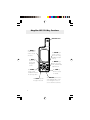
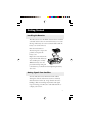
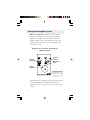
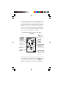
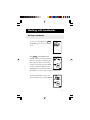
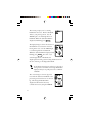
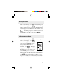
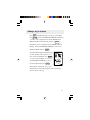
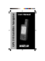
GPS 310 Satellite Navigator
User Manual
WARNINGS
A measure of knowledge by the user is required for proper and
safe use of the Magellan GPS 310™. READ THE USER MANUAL &
WARRANTY COMPLETELY.
Use Good Judgment
This product is an excellent navigation aid, but it does not replace
the need for careful orientation and good judgment. Never rely
solely on one device for navigating.
Use Care to Avoid Inaccuracies
The Global Positioning System (GPS) is operated by the U.S.
Government, which is solely responsible for the accuracy and the
maintenance of GPS. Certain conditions can make the system less
accurate.
No part of this Manual may be reproduced or transmitted in any
form or by any means, electronic or mechanical, including
photocopying and recording, for any purpose other than the
purchaser’s personal use, without the written permission of
Magellan Corporation.
© Copyright 2000 by Magellan Corporation. All rights reserved.
Magellan™ and GPS 310™ are the trademarks of Magellan
Corporation.
P/N 630786 B
TABLE OF CONTENTS
Introduction .................................................... 1
Welcome to the Magellan GPS 310 ..................................... 1
GPS 310 Description ........................................................... 1
Magellan GPS 310 Key Functions ....................................... 2
Getting Started ................................................ 3
Installing the Batteries ......................................................... 3
Getting Signals from Satellites ............................................. 3
Initializing the Receiver - EZStart ........................................ 4
Computing a Position .......................................................... 5
Basic Operation ............................................... 7
Saving a Position Fix ............................................................ 7
Creating a Landmark ........................................................... 8
Viewing the POSITION Screen ........................................... 9
Viewing the NAVIGATION Screens .................................. 10
Creating a GOTO Route ................................................... 13
Summary ........................................................................... 14
Working with Landmarks .............................. 15
Viewing a Landmark .......................................................... 15
Editing a Landmark ........................................................... 16
Deleting a Landmark ......................................................... 16
i
GPS 310 TOC
1
10/18/99, 9:27 AM
Working with Routes..................................... 17
Creating a Route ................................................................ 17
Viewing a Route ................................................................ 19
Activating/Deactivating a Route ........................................ 20
Deleting a Route ................................................................ 21
Adding Legs to a Route ...................................................... 21
Activating a Leg in a Route ................................................ 22
Editing a Leg in a Route .................................................... 23
Deleting a Leg From a Route ............................................. 24
Reversing a Route .............................................................. 24
Additional Features ....................................... 25
Viewing the Time and Date ............................................... 25
Viewing Elevation .............................................................. 25
Viewing Battery Life .......................................................... 25
Changing Coordinate Systems ........................................... 26
Changing Map Datums ..................................................... 27
Changing Distance Units ................................................... 28
Changing Time Display and Time ..................................... 28
Changing North Reference ................................................ 29
Initializing the Receiver (EZSTART) ................................. 29
Activating the Demo Mode ................................................ 30
Setting Display Contrast .................................................... 31
Using the Trip Odometer ................................................... 31
Connecting to External Devices .................... 32
NMEA Data Messages ................................... 34
Troubleshooting ............................................ 41
Frequently Asked Questions .............................................. 42
Icons .................................................................................. 44
Contacting Magellan ......................................................... 45
ii
GPS 310 TOC
2
10/18/99, 9:27 AM
Accessories ..................................................... 46
Attaching the Wrist Lanyard .......................... 47
Shipping/Transporting .................................. 48
Glossary ......................................................... 49
Index ............................................................. 52
iii
GPS 310 TOC
3
10/18/99, 9:27 AM
iv
GPS 310 TOC
4
10/18/99, 9:27 AM
Introduction
Welcome to the Magellan GPS 310
Congratulations on your purchase of the Magellan GPS 310
satellite navigator. The GPS 310 is an easy-to-use GPS
receiver designed to get you out in the “Great Outdoors”
rather than spending hours reading a User’s Manual. There
are, however, a few items that you need to be familiar with so
it is suggested that you follow along at least through the
chapter on Basic Operation.
Before you begin, make sure that your package includes the
items listed on the GPS 310 box. If any items are missing or
damaged, contact your Magellan dealer or retailer.
GPS 310 Description
The GPS 310 is a self-contained hand-held GPS receiver
designed for general purpose position locating and navigation.
It has a built-in antenna located at the top of the receiver, a
backlit display, and keypad. Using two AA batteries, inserted
from the battery door found at the back of the receiver, the
GPS 310 will operate for up to 20 hours.
1
Magellan GPS 310 Key Functions
GPS Antenna
G P S 310
The ENTER key
confirms data
entries or menu
selections.
The NAV key
accesses the
Position and
Navigation
screens.
The GOTO key is
used to create a
direct route to any
landmark stored in
memory.
ENTER
NAV
MARK
The MARK key is
used to create
landmarks and store
the current position.
The LIGHT key turns
the light on and off.
2
GOTO
MENU
The MENU key is
used to access the
route, landmark and
setup functions.
PWR
The PWR key
turns the receiver
on and off.
The ARROW pad is used to
enter landmark names, and
scroll through the series of
screens and menu selections.
Getting Started
Installing the Batteries
The GPS 310 uses two AA alkaline batteries that are installed
at the back of the receiver. To remove the battery cover, turn
the ring of the battery door screw counterclockwise until the
battery cover can be removed.
Insert the new batteries as
shown, being sure to respect the
polarities, and replace the
battery cover.
+
+
-
Replace the screw and turn the
ring clockwise until the battery
door is held in place securely.
While the battery door does
provide the waterproofing seal
to the batteries, you should avoid overtightening the battery
door screw.
Getting Signals from Satellites
Since the GPS 310 receives information from satellites
orbiting the earth, the antenna needs to have a relatively
unobstructed view of the sky. Large obstructions such as
buildings, cliffs, and overhangs may interfere with signal
reception causing your GPS 310 to take additional time to
compute your location.
3
The GPS 310 is designed to fit
comfortably in your hand. Hold
the receiver with the antenna
towards the sky.
Initializing the Receiver - EZStart
Before using your GPS 310 for the first time, the receiver
needs to know its approximate location. Using Magellan’s
EZStart procedure, the GPS 310 will prompt you for the
information it requires when you turn it on for the first time.
You do not need to initialize your receiver each time you use
it. Follow these steps to initialize the GPS 310 if this is the
first time you are using it.
� Press
PWR
to turn the GPS 310 on.
� SELECT REGION. Use the ARROW pad to change the
flashing text to select the appropriate region for your
present location. Press
ENTER
� SELECT COUNTRY or STATE. Use the ARROW pad
to change the flashing text to select the country or state for
your present location.
Press
4
ENTER
� ENTER ELEVATION. Use the ARROW pad to enter
the approximate elevation for your position. If unknown,
leave the elevation at 0. Press
ENTER
� ENTER TIME. Use the ARROW pad to enter your
present time. Press
ENTER
� ENTER DATE. Use the ARROW pad to enter the date.
Press
ENTER
The GPS 310 then displays the POSITION screen and
automatically begins searching for satellites that it knows are
in this area for the date and time
you entered.
The display shown here may differ
from yours depending upon the
information you selected in steps 2
and 3. As the GPS 310 scans the
sky, the arrow in the circle will swing
around pointing to a satellite and
displays, in the center of the circle,
that satellite’s elevation above the horizon.
Computing a Position
The GPS 310 will begin to acquire information from the
satellites and use this information to compute your current
position (called a position fix). Whether you have just
5
completed the initialization process or have just turned your
GPS 310 on, the GPS 310 will display the following screens
in the order shown.
As the GPS 310 searches for satellites,
some of the small circles around the
large circle will become black indicating
that the GPS 310 is tracking that
satellite and receiving information. The
number at the bottom right of the
screen displays how many satellites are
being tracked.
After the GPS receiver has received
positioning data from at least three
satellites (approximately 2-3 minutes), it
will begin computing a position fix
based upon the information it is
receiving. As soon as a position fix is
computed, the receiver switches to the
navigation screen displaying the moving
compass. The word “TRACKING” is
displayed in the lower right corner indicating that the receiver
is computing position fixes.
Note: If the receiver has not acquired a position fix in
approximately 10 minutes, refer to the troubleshooting
section of this manual.
More information on these screens and the information they
display can be found in the next chapter.
6
Basic Operation
Saving a Position Fix
Position fixes can be saved in memory for use later when you
want to return to that position. Saved position fixes are
referred to as landmarks or LMK.
To save (mark) your current position press
MARK .
Receiver-Generated Name: The GPS 310
prompts you to enter a name or accept the
receiver-generated name for this landmark.
To accept the receiver-generated name
(LM01 - LM99), press
ENTER
To quickly save a position fix, press
MARK
MARK .
User-Created Name: To create a name (up to four characters), use the UP/DOWN arrows to change the character and
the LEFT/RIGHT arrows to move the cursor to the left or
right respectively. After you have input the desired landmark
name press
Press
ENTER
ENTER
ENTER
.
to accept the current latitude and press
again to accept the current longitude.
Shortcut: Press
MARK at
anytime while viewing this screen
to quickly save the position.
7
Creating a Landmark
To create a landmark at a location which is not your current
position, use the same procedure as saving a position with the
additional step of inputting different latitude/longitude
coordinates.
To create a landmark press
MARK .
The GPS 310 prompts you to enter
a name or accept the receivergenerated name for this landmark.
When the desired name is displayed
at the top of the screen press
ENTER
.
Use the ARROW pad to change the
latitude and press
ENTER
to accept.
Use the ARROW pad to change the longitude and press
ENTER
to accept.
The newly created landmark is stored in memory and you
are returned to the screen that was displayed when you
pressed the MARK key.
Shortcut: Press
MARK
at anytime while viewing this screen
to quickly save the position.
8
Viewing the POSITION Screen
The POSITION screen displays the coordinates for your last
computed position and information about any satellites that
are visible. It can be accessed by pressing the
Latitude and
Longitude
Satellite Elevation
Degrees above the
horizon of the satellite
indicated by the satellite
pointer.
NAV
key.
North Indicator
Satellite
Pointer
Number of
satellites being
used.
Satellite Icons
Visible but not tracked.
Satellite is being tracked.
Tracking Indicator
Appears when the receiver
has acquired enough
information from the
satellites to compute a
position fix.
You may sometimes notice that the number of satellites being
tracked differs from the number of satellites being displayed
graphically. This is due to more than one satellite being
tracked in the same general area.
9
Viewing the Navigation Screens
Without an Active Route. Without an active route the
navigation screen displays your heading and the speed at
which you are traveling. The lower portion of the screen
displays a moving compass. The triangle at the top of the
compass points in the direction you are traveling and the
arrow points to north.
Navigation Screen without an Active Route
(Moving Compass)
Current
Heading
Current
Speed
Direction of
Travel
North
Indicator
Tracking Indicator
Appears when enough
satellites have provided
information to compute
position fixes.
The navigation screens display your speed of travel. In order
for the North Indicator to be valid and the speed to be
displayed, you must be moving at a speed greater than 2 miles
per hour.
10
With an Active Route. When you have an active route the
navigation screen still displays your heading and speed but
also includes the bearing and distance to your destination.
The moving compass is then replaced with steering information. You can use the graphical representation or the steering
indicator to assist in directing you towards your final destination.
Navigation Screen with an Active Route
(Steering)
Destination
Landmark
Bearing to
Destination
Current
Heading
Destination
Icon
Distance to
Destination
Current
Speed
North
Indicator
Steering Indicator
Indicates the number of
degrees to turn, right or left,
to destination landmark.
Destination
Pointer
Tracking Indicator
Appears when enough
satellites have provided
information to compute
position fixes.
In the screen above you are traveling with a heading of 56°
while your destination bearing is 34°. This would indicate
that you need to turn left 22° to be on a straight line to your
destination. The circle and arrow display the same information but in a visual manner. The triangle points in the
direction you are traveling and the arrow points towards your
destination.
11
A second navigational screen is also provided while you have
an active route. This screen is very similar to the first screen
except that the distance to the destination has been replaced
with XTE (cross track error, the distance left or right that
you are off course) and heading has been replaced with TTG
(time to go). This screen provides you additional information to aid you in navigating to your destination.
Second Navigation Screen with an Active Route
(Steering)
Destination
Landmark
Cross Track
Error
Distance left or right
of the desired
Courseline.
Bearing to
Destination
Current
Speed
Time to Go
Time remaining to
arrive at the
destination at your
present speed and
heading
North
Indicator
Destination
Icon
Destination
Pointer
Steering Indicator
Indicates the number
of degrees to turn,
right or left, to
destination landmark.
Tracking Indicator
Appears when enough
satellites have provided
information to compute
position fixes.
The navigation screens and the position screen are connected
to one another in a circular loop. Pressing the
NAV
key or
using the ARROW pad while viewing one of the position or
navigation screens moves you to the next screen in the loop.
12
Creating a GOTO Route
The simplest form of a route is a one-leg route called a
GOTO route (you are GOing TO a destination). This is
routing you from your current position to a landmark stored
in memory All that is required to create a GOTO route is
that you have saved a landmark indicating the location of your
destination.
To create (activate) a GOTO Route:
From any screen, press
GOTO screen appears.
GOTO
. The
To select a different landmark, use the
LEFT/RIGHT ARROWS until the
desired destination landmark is displayed.
Press ENTER or GOTO . The display
returns to the Navigation screen showing
the name of the GOTO destination at
the top of the screen.
13
If the receiver is not tracking sufficient satellites to
compute a position fix, the start of the newly created
GOTO route will be the last position computed,
which may not be the current position.
This GOTO route will remain the active route until a new
GOTO route is created, a multileg route is activated, or the
receiver is turned off. Turning off the receiver deactivates
any GOTO route.
Summary
This completes the basic operation of the GPS 310. At this
time it would be a good idea to put what you know to
practice. Pick a location that you would want to come back
to, your home for example. Take a position fix of the location
and save it to memory, giving it a name that you will later
associate with this location. Then travel a few miles away with
your receiver, stop and take another position fix. Now use the
GOTO
key to set a GOTO route and highlight the landmark
you created before and press
ENTER
.
Your GPS 310 is ready to navigate you back to where you
started. The navigation screens are now showing you the
distance and bearing back to the original landmark. As you
begin moving, the GPS 310 will begin using your speed and
direction to compute the shortest distance back to your
original starting point as well as how long it will take you to
get there.
The following chapters provide you with more information on
using your GPS 310 that build upon what you’ve learned.
14
Working with Landmarks
Viewing a Landmark
To view a stored landmark press
MENU
until LMKS appears at the top of the
screen.
Press
ENTER
. The BEARING/DIS-
TANCE screen for the first landmark in
the receiver’s memory is displayed with
the bearing and distance from the last
computed position fix to that landmark.
To select a different landmark, use the
LEFT/RIGHT arrows until the name of
the landmark you wish to view is at the top of the screen.
To view the POSITION screen of the
selected landmark, press the UP ARROW.
15
Editing a Landmark
Following the instructions under Viewing a Landmark, use the
LEFT/RIGHT arrows to select the landmark you wish to edit.
Press the UP ARROW until the screen displays PRESS ENT
TO EDIT, then press
ENTER
.
You can modify the landmark name and/or the coordinates for
the landmark by using the UP/DOWN arrows to change the
information and press
ENTER
to move to the next line. If
the landmark you are editing is used in a route, the route will
be modified to reflect the changes you made to the landmark.
Deleting a Landmark
Following the instructions under Viewing a Landmark, use the
LEFT/RIGHT arrows to select the landmark you wish to
delete.
Press the UP ARROW until the screen displays PRESS ENT
TO DELETE, then press
ENTER
. Use the LEFT/RIGHT
ARROWs to confirm (YES or NO) and press
ENTER
.
If the landmark is used in a route or is the destination
landmark in a GOTO route, the GPS 310 alerts you
that the landmark cannot be deleted. Remove the
landmark from the route and repeat.
16
Working with Routes
The route function allows you to link a series of landmarks
and travel, point by point, to a final destination.
D
Leg 1
g
C
Leg 2
Le
A
3
B
The route depicted here is a three-leg route. Leg 1 extends
from landmark A to landmark B, leg 2 from landmark B to
landmark C, and leg 3 from C to D. The GPS 310 gives you
information on the NAV screens that directs you to the
destination of each leg sequentially.
Creating a Route
A route can contain up to 10 legs using any of the landmarks
stored in memory. If there is a route already in memory you
must delete the existing route before you can create a new one.
Access the Route Menu by pressing
MENU
until ROUTE
appears at the top of the screen. The display should say
“PRESS ENT TO CREATE.”
NOTE: If the display says PRESS ENT TO VIEW there is
an existing route and you must delete the existing route before
creating a new one. (See Deleting a Route for details.)
Press
ENTER
.
17
The receiver prompts you for a starting
landmark for the route. The first landmark,
*POS, is your present position. Use the
ARROW pad to scroll through the list of
landmarks. When the desired landmark is
displayed (and flashing) press
ENTER
.
The display changes to allow the selection of
the landmark to be used as the end of the
first leg in the route. Use the ARROW pad
to scroll through the list of landmarks.
When the desired landmark is displayed (and
flashing) press
ENTER
. Note that as you
scroll through the list of landmarks, the
display updates showing you the bearing and distance from
the start of this leg to the displayed landmark.
If the distance from the start of the leg to the end of
the leg is below 0.10 miles, the message INVALID is
displayed and you are prompted to select a different
landmark.
The screen changes to the next leg in the
route with the destination landmark of the
previous leg inserted as the start of the next
leg. The message END ROUTE is
displayed in the TO field. You may
continue this route by using the ARROW
18
pad to select a landmark as the destination for this leg or press
ENTER
to signal the GPS 310 that this was the last leg in the
route and you are finished creating a route.
Continue this process for each leg in the route remembering
to press
ENTER
with END ROUTE displayed in the TO
field to finish up the route. If you accidently pressed the
ARROW pad but you meant to end the route, you can still
end the route by continuing to press the ARROW pad until
END ROUTE is displayed again.
A route may contain no more than ten legs and the
GPS 310 automatically saves the route and returns to
the Route Menu as soon as Leg 10 is entered.
After the route has been created, the GPS 310 automatically
activates the route and begins providing navigation information for the route.
Viewing a Route
You can view a summary of the route in memory as well as
viewing the individual legs of the route. All editing commands are accessed from the View Route function as well.
With a route in memory, press
MENU
until ROUTE appears
at the top of the display. Press
ENTER
.
19
The first screen displayed is the ROUTE
SUMMARY screen. This screen displays
the start and end landmark for the entire
route as well as the total distance of the
route.
Use the LEFT/RIGHT ARROWs to view
the legs in the route. The leg screen
displays the FROM and TO landmark for
the leg as well as the distance and bearing
for the leg. The circle graphically displays
the bearing for the leg. Continue pressing
the LEFT/RIGHT ARROWs to step
through the other legs in the route,
eventually returning to the ROUTE SUMMARY screen.
Activating/Deactivating a Route
With a route in memory, press
MENU
until ROUTE appears
at the top of the display. Press
ENTER
. Press the UP
ARROW. If the route is currently active, the display indicates:
ENT TO DEACTVATE. If the route is currently deactivated,
the display indicates: ENT TO ACTIVATE. Pressing
ENTER
will activate or deactivate the route depending upon its
present status. After a route is deactivated, the route summary
is displayed. If a route is activated, the NAV screen is
displayed.
20
Deleting a Route
With a route in memory, press
MENU
until ROUTE appears
at the top of the display. Press
ENTER
. While still viewing
the Route Summary screen, press the UP ARROW three times
until the display indicates PRESS ENT TO DELETE. Press
ENTER
. You will be prompted to confirm the deletion. Use
the ARROWs to select YES or NO and press
ENTER
.
Adding Legs to a Route
With a route in memory, press
MENU
until ROUTE appears
at the top of the display. Press
ENTER
.
While still viewing the Route Summary
screen, press the UP ARROW until the
display indicates PRESS ENT TO
ADDLEG. Press
ENTER
. The display
changes to the Add Leg screen with END
ROUTE flashing. As in creating a route,
use the ARROW pad to select the new
landmark for this leg. With the new TO landmark flashing,
press
ENTER
. The newly created leg is added to the route.
The process of adding a leg continues until you select END
ROUTE or the route is full.
21
Activating a Leg in a Route
As you are navigating you may decide that you no longer wish
to continue on the leg that you are now using. Instead you
wish to use another leg of the route. You will need to activate
the leg of the route with the desired destination (TO landmark).
Press
MENU
until ROUTE appears at the top of the display.
Press
ENTER
. Use the LEFT/RIGHT ARROWs until the leg
you wish to activate is displayed. Press the UP ARROW. If
the leg is not active, the display indicates ENT TO ACTIVATE. Press
ENTER
. The leg has become activated, the
NAV screen is displayed, and the receiver begins to compute
the necessary information to continue you on the route using
the leg you selected.
If the display indicates ENT TO DEACTVATE, it means that
the receiver is using this leg to compute the navigational
information. Pressing ENTER at this screen not only
deactivates the leg and returns to the leg summary screen, but
deactivates the route as well.
22
Editing a Leg in a Route
Press
MENU
until ROUTE appears at the top of the display.
Press
ENTER
. Use the LEFT/RIGHT ARROWs until the leg
you wish to edit is displayed. Press the UP ARROW until
PRESS ENT TO EDIT is displayed and press
ENTER
.
The Edit Leg screen is displayed with the FROM landmark
flashing. Use the LEFT/RIGHT ARROWs to select a new
FROM landmark and press
ENTER
.
The TO landmark begins flashing alerting
you that the GPS 310 is ready for you to
select a new TO landmark. Press
ENTER
to accept the TO landmark as it is or use
the LEFT/RIGHT ARROWs to select a
new TO landmark and press
ENTER
.
The leg before and after the one you just
edited will be automatically changed to reflect the changes
that were made to this leg.
23
Deleting a Leg From a Route
Press
MENU
until ROUTE appears at the top of the display.
Press
ENTER
. Use the LEFT/RIGHT ARROWs to find the
leg of the route that you want to delete. Press the UP
ARROW until PRESS ENT TO DELETE is displayed and
press
ENTER
.
The GPS 310 prompts you to confirm the deletion of the leg.
Use the LEFT/RIGHT ARROW to select (flashing) YES to
delete or NO to cancel.
If you attempt to delete a leg that causes the route to
contain a leg that is under the 0.1 mile leg distance
limitation, the receiver will display the message
INVALID DELETE.
Reversing a Route
Press
MENU
until ROUTE appears at the top of the display.
Press
ENTER
. Press the DOWN ARROW until PRESS
ENT TO REVERSE is displayed and press
ENTER
.
The GPS 310 prompts you to confirm the action. Use the
LEFT/RIGHT ARROW to select (flashing) YES to reverse or
NO to cancel and press
24
ENTER
.
Additional Features
Viewing the Time and Date
You can view the current time and date (obtained from the
satellites) by repeatedly pressing the
is displayed at the top of the screen.
MENU
key until TIME
Viewing Elevation
You can view the last computed elevation for your GPS 310
by repeatedly pressing the
MENU
key until ELEVATION is
displayed at the top of the screen.
Viewing Battery Life
You can view the estimated battery life remaining by
repeatedly pressing the
MENU
key until POWER is
displayed at the top of the screen.
Full Battery
Life
40-60%
Battery Life
Low
Batteries
25
Changing Coordinate Systems
You may wish to change the coordinate system that your GPS
310 uses to display the position and landmarks coordinates.
You have the following options: LAT/LON using degree/
minutes (DEGMIN), LAT/LON using degree/minutes/
seconds (DEGMINSEC),Universal Transverse Mercator
(UTM), OSGB, Irish, Swiss, Swedish, Finnish, French, or
German. The choice you make will depend upon the maps or
charts you may be using. You want your GPS 310 to be
displaying the coordinates in the same mode that your map or
chart uses.
The following example shows the same position in three
different modes.
LAT/LON
(DEGMIN)
Press the
MENU
LAT/LON
(DEGMINSEC)
UTM
key until SETUP is displayed at the top of
the screen and press
ENTER
. Press
ENTER
again and the
currently used coordinate system begins to flash. Use the
RIGHT/LEFT ARROWs to scroll through the list of
coordinate systems and press
ENTER
when the desired system
is displayed. Some coordinate systems require additional zone
or format information. Use the arrow pad and
select the proper zone or format.
26
ENTER
to
Changing Map Datums
If you are using a map (or chart) in conjunction with your
GPS 310 you need to insure that the datum used by the GPS
310 matches the one used in creating the map. The map
datum can usually be found in the legend box of the map or
chart. The GPS 310 offers the choices of WGS84 (default),
NAD27, AUST 84, EUROPE 50, GRB 36, IRELAND, KKJ,
RT90, S AMERICA 69, SWISS, FRENCH, GERMAN, and
TOKYO.
Press the
MENU
key until SETUP is displayed at the top of
the screen and press
ENTER
. Use the RIGHT ARROW until
SETUP MAP DATUM is displayed. Press
ENTER
again, the
currently used map datum begins to flash. Use the RIGHT/
LEFT ARROWs to scroll through the list of map datums and
press
ENTER
when the desired datum is displayed.
Some coordinate systems can be used only with a
specific datum (i.e., OSGB coordinate system can be
used only with the GRB 36 datum). Your GPS 310
automatically selects the proper datum when you
select that coordinate system and will not allow you
to change the datum until you select a different
coordinate system.
27
Changing Distance Units
Your distance units can be in miles and miles per hour (MIMPH), nautical miles and knots (NM-KTS), or kilometers
and kilometers per hour (KM-KPH). To change the units,
press
MENU
and press
until SETUP is displayed at the top of the screen
ENTER
. Use the RIGHT ARROW until SETUP
UNITS is displayed. Press
ENTER
again and, the distance
unit of measure begins to flash. Use the RIGHT/LEFT
ARROWs to scroll through the list of units and press
ENTER
when the desired unit of measure is displayed.
Changing Time Display and Time
To change the way that time is displayed (12 HOUR- default,
24 HOUR, or UT), repeatedly press
MENU
displayed at the top of the screen and press
until SETUP is
ENTER
. Use the
RIGHT ARROW until SETUP TIME is displayed. Press
ENTER
again and the time display begins to flash. Use the
RIGHT/LEFT ARROWs to scroll through the list and press
ENTER
to select. The screen changes to TIME SET. Use the
ARROW pad to set the time and press
ENTER
when done.
(You are not prompted to set the time if you selected UT as
the time format.)
When you change your clocks because of daylight savings
time, remember to change the time in your GPS 310.
28
Changing North Reference
The GPS 310 uses magnetic north as a default reference for all
navigation computations. You can change this to true north
(good if you are also using a map) or back to magnetic north
(default, good to use if you are using a compass) under the
SETUP menu. Press the
MENU
key until SETUP is dis-
played at the top of the screen and press
ENTER
. Use the
RIGHT ARROW until SETUP NORTH REF is displayed.
Press
ENTER
again, the north reference begins to flash. Use
the RIGHT/LEFT ARROWs to scroll between MAGNETIC
and TRUE and press
ENTER
to select.
Initializing the Receiver (EZSTART)
If you desire to re-initialize the receiver, (for example, you
have moved more than 300 miles since the last time the
receiver was turned on) you can do so in the SETUP menu.
Press
MENU
and press
until SETUP is displayed at the top of the screen
ENTER
. Use the RIGHT ARROW until SETUP
PRESS ENT TO EZSTRT is displayed. Press
ENTER
again
and the receiver prompts you to enter the necessary data.
SELECT REGION. Use the ARROW pad to change the
flashing text to select the appropriate region for your present
location. Press
ENTER
.
29
SELECT COUNTRY or STATE. Use the ARROW pad to
change the flashing text to select the country or state for your
present location.
Press
ENTER
.
ENTER ELEVATION. Use the ARROW pad to enter the
approximate elevation for your position. If unknown, leave
the elevation at 0. Press
ENTER
.
ENTER TIME. Use the ARROW pad to enter your present
time. Press
ENTER
.
ENTER DATE. Use the ARROW pad to enter the date.
Press
ENTER
.
Note: The prompts to enter time and date will not appear if
your receiver has already collected this information from the
satellites.
Activating the Demo Mode
To turn on the Demo Mode, press
until SETUP is
MENU
displayed at the top of the screen and press
ENTER
. Use the
RIGHT ARROW until SETUP DEMO is displayed. To
toggle between ON or OFF, press
ENTER
. The present
status, on or off, will flash. Use the LEFT/RIGHT ARROWs
to switch between on and off and press
ENTER
.
While in the Demo Mode, the receiver displays sample
information on the POSITION and both NAVIGATION
screens.
30
Setting Display Contrast
To adjust the contrast of the display, press
MENU
until SETUP is displayed at the
top of the screen and press
ENTER
. Use
the LEFT/RIGHT ARROW until SETUP
CONTRAST is displayed and press
ENTER
. Use the LEFT/RIGHT AR-
ROW keys to change the contrast to the
desired level and press
ENTER
.
Using the Trip Odometer
Press
MENU
until the ODOMETER is
displayed. The odometer will keep track
of the distance you have traveled while
using your GPS 310. To reset the
odometer press
ENTER
. You will be asked
to confirm that you really want to reset the
odometer to zero. Use the LEFT/RIGHT
ARROWs to highlight (blinking) YES and
press
ENTER
.
31
Connecting to External Devices
The GPS 310 is designed to interface to a PC or other devices
using a data cable. The GPS 310 continuously outputs
NMEA messages through the data port at a rate of every 1
second. The GSV message is output all the time including
when the receiver is not computing fixes. After the first fix is
computed, GSA, GLL, GGA and RMC messages are also
output. These messages contain position, time, date, satellite
position as well as other status information. These messages
can be used by a variety of navigation software packages
available for the personal computer.
If the receiver is computing fixes and has a route set (either a
GOTO or a multi-leg route) the RMB and APB messages are
also output. The RMB and APB contain information
(steering, distance to destination, etc.) used to navigate to the
route destination. These messages are used by autopilots and
marine navigation software.
Connecting the GPS 310 to a Personal Computer (PC)
Connect one end of the data cable to the back of the GPS 310
and connect the other end of the data cable (the end with the
DB9 connector) to the serial port on the personal computer.
Now any application that you run on your PC that accepts
NMEA messages will be able to receive that information from
your GPS 310.
NOTE: Be sure that your PC software is set to the COM
port that you connected your data cable to and that the baud
rate is set to 4800 baud.
32
Connecting the GPS 310 to an Autopilot Device
To connect the GPS 310 to an autopilot or other external
device you may need to cut off the DB9 connector and “hard
wire” the cable to the device. The cable configuration is as
follows:
Orange: Data Out
Yellow: Data In
Black: Ground
Red: Power (DO NOT USE)
Refer to the manual on the external device and connect the
wires to their proper place. Be careful and double check your
connections before applying power to the external device as an
improper connection could damage the GPS 310 and void its
warranty.
Connecting the GPS 310 to a DGPS Receiver
The GPS 310 is capable of receiving differential corrections
from a differential receiver for improved accuracy. By
connecting a differential beacon receiver (DBR), such as the
Magellan DBR IV, to the GPS 310, corrections are automatically applied to the position and velocity computed by the
receiver. If corrections are being applied to the GPS 310,
“DGPS” will appear on the top of the position screen.
The GPS 310 accepts standard RTCM v2.1 messages at 4800
baud rate. You can use either the Data Cable, Power/Data
Cable or PC Cable with Cigarette Lighter to connect the GPS
310 to the DBR.
33
NMEA Data Messages
NMEA DATA MESSAGES. NMEA data is output at 4800
baud, 8, N, 1, checksum off. These settings are acceptable to
most equipment and software applications.
Your GPS receiver outputs the following NMEA 0183 version
2.1 messages.
GSA, GSV, GLL, GGA, RMB, RMC and APB.
Vers. 2.1 NMEA is recommended for navigation data,
satellite data and autopilots.
NMEA Message Definitions
34
APB
Revised autopilot message contains all of the above plus:
heading to steer toward destination, bearing from the
present position to the destination (magnetic or true).
GGA
GPS position, time, fix quality, number of satellites used,
HDOP (Horizontal Dilution of Precision), differential
reference information, and age.
GLL
GPS-derived latitude, longitude, and time of fix.
GSA
GPS receiver operating mode, satellites used in the
navigation solution reported by the $--GGA sentence and
DOP (Dilution of Precision) values.
GSV
Number of satellites in view, satellite numbers, elevation,
azimuth, and SNR value.
RMB
Data status, cross track error, direction to steer, origin,
destination landmark, landmark location, bearing to
destination, and velocity toward the destination.
RMC
Time, latitude, longitude, speed, heading, and date.
NMEA 0183 VERSION 2.1
APB
Autopilot Sentence “B”
1 2 3
4 5 6 7 8
9 10 11 12 13 14
APB,A,A,x.x,a,N,A,A,x.x,a,c—c,x.x,a,x.x,a*hh
1
Status: A = Data valid
V = Loran-C Blink or SNR warning
V = general warning flag for other
navigation systems when a
reliable fix is not available.
2
Status: V = Loran-C cycle lock warning flag
A = OK or not used
3
Magnitude of XTE
4
Direction to steer (L, R)
5
XTE units, nautical miles
6
Status:
A = arrival circle entered
7
Status:
A = perpendicular passed at waypoint
8-9
Bearing origin to destination, M/T
10
Destination waypoint ID
11-12 Bearing, present position to destination,
Magnetic or True
13-14 Heading to steer to destination waypoint,
Magnetic or True
35
GGA
Global Positioning System Fix Data
1
2
3 4
5 6 7 8
9 10 11
GGA,hhmmss.ss,1111.11,a,yyyyy.yy,a,x,xx,x.x,x.x,M,x.x,
12 13 14
M,x.x,xxxx*hh
1
UTC of Position
2-3 Latitude - N/S
4-5 Longitude - E/W
6
GPS Quality Indicator
0 = fix not available or invalid
1 = GPS SPS Mode, Fix valid
2 = Differential GPS, SPS Mode, fix valid
3 = GPS PPS Mode, fix valid
7
Number of satellites in use (00-12, may be
different from the number in view)
8
Horizontal dilution of precision
9
Antenna altitude above/below mean sea level
10
Units of antenna altitude, meters
11
Geoidal separation - difference between the WGS84 earth ellipsoid and mean sea level (geoid), “” = mean sea level below ellipsoid
12
Units of geoidal separation, meters.
13
Age of Differential GPS data - Time in seconds
since last SC104 Type 1 or 9 update, null field
when DGPS is not used
14
Differential reference station ID, 0000-1023
36
GLL
Geographic Position — Latitude/Longitude
1
2 3
4 5
6
GLL,1111.11,a,yyyyy.yy,a,hhmmss.ss,A*hh
1-2
Latitude, N/S
2-3
Longitude, E/W
4
UTC of position
6
Status
A = Data valid
V = Data not valid
GSA
GPS DOP and Active Satellites
GPS receiver operating mode, satelites used in
the navigation solution reported by the $--GGA
sentence, and DOP values.
1 2 3
4
GSA,a,x,xx,xx,xx,xx,xx,xx,xx,xx,xx,xx,xx,xx,
5
6 7
x.x,x.x,x.x*hh<CR><LF>,
1
Mode: M=Manual, forced to operate in 2D or
3D mode,
A=Automatic, allowed to automatically
switch 2D/3D
2
Mode: 1= Fix not available, 2=2D, 3=3D
3-4 PRN numbers of satellites used in solution
(null for unused fields)
5
PDOP
6
HDOP
7
VDOP
37
GSV
GPS Satellites in View
Number of satellites (SV) in view, PRN numbers,
elevation, azimuth and SNR value. Four satellites maximum per transmission, additional
satellite data sent in second or their message.
Total number of messages being transmitted and
the number of messages being transmitted is
indicated in the first two fields.
1 2 3 4 5 6 7
8 9 10 11
GSV,x,x,xx,xx,xx,xxx,xx..........xx,xx,xxx,xx*hh<CR><LF>
1
Total number of messages, 1 to 3
2
Message number, 1 to 3
3
Total numer of satellites in view
4
Satellite PRN number
5
Elevation, degrees, 90° maximum
6
Azimuth, degrees True, 000 to 359
7
SNR (C/No) 00-99 dB, null when not tracking
8-9 2nd-3rd SV
10-11 4th SV
Notes: 1) Satellite information may require the
transmission of multiple messages. The first
field specifies the total number of messages,
minimum value 1. The second field identifies
the order of this message (message number),
minimum value 1.
2) A variable number of “PRN-Elevation-AzimuthSNR” sets are allowed up to a maximum of four
sets per message. Null fields are not required
for unused sets when less than four sets are
transmitted.
38
RMB
Generic Navigation Information (immediately
follows RMC)
1 2
3 4
5
6
7 8
9 10
RMB,A,X.XX,a,c--c,c--c,1111.11,a,yyyyy.yy,a,x.x,
11
12 13 14
x.x,x.x,A *hh
1
Data Status
(A = valid,
V = invalid)
2-3 XTE, naut. miles and direction to steer (L
or R) [If XTE exceeds 9.99 NM, display 9.99
in field 2.]
4
Origin waypoint ID
5
Destination waypoint ID
6-7 Destination Waypoint Latitude (N or S)
8-9 Destination Waypoint Longitude (E or W)
10
Range naut. miles, present fix to destination waypoint Great Circle. [If range exceeds
999.9 nm, display 999.9.]
11
Bearing, True, Great Circle, Present fix to
dest. waypoint
12
13
14
Closing velocity to destination, knots
Arrival (OR’ed arrival circle and crossing
of line which is perpendicular to the course
line and which passes through the destination
waypoint.)
CHECKSUM
(Mandatory in this sentence.)
39
RMC
Transit Specific (to be followed by RMB)
1
2 3
4 5
6 7
8 9
10
RMC,hhmmss.ss,A,1111.11,a,yyyyy.yy,a,x.x,x.x,xxxxxx,x.x,a
*hh
1
2
Time, UTC of position fix
Status
(A = valid,
V = Navigation receiver
warning)
3-4 Latitude at UTC time, N or S
5-6 Longitude at UTC time, E or W
7
Speed over ground, knots
8
Course over ground, degrees
9
Date
10
Magnetic variation, degrees
11
Magnetic variation, sense (E or W)
12
CHECKSUM
(DDMMYY)
(Mandatory in this sentence)
The formats listed are NMEA formats and Magellan receivers may not
output all of the information listed for a particular format.
A complete copy of the NMEA specifications can
be obtained from:
NMEA, PO Box 3435 New Bern, NC 28564-3435
40
Troubleshooting
Does not turn on:
1. Check to insure that the batteries are installed correctly
and that the battery terminals are clean.
2. Replace the batteries.
Takes more than 10 minutes to get a position fix:
1. If there are large obstacles nearby or overhead, move to
a new location with a clear view of the sky and turn
the receiver back on.
2. Make sure that the antenna is pointing up and that it
is a reasonable distance from your body.
3. Check that the time is correct. If not, reset the time
following the instructions for “Changing Time Display
and Time” on page 28.
4. If the receiver still does not get a position fix within 10
minutes, you may wish to repeat the EZSTART
initialization procedure found on page 29.
Cannot view the second navigation screen:
1. The second navigation screen is displayed only if you
have an active route or GOTO. Activate a route or
GOTO and use the NAV key to scroll to the second
navigation screen.
Destination Pointer does not point to the destination:
1. Note that much of the navigation information is based
upon your movement. If you are standing still the
41
navigation information (destination pointer, etc.) is not
updated until you are moving. (The receiver is unable to
detect which way you are facing while you are stationary.)
Position coordinates on your receiver do not match the
location on your map.
1. Make sure that your receiver is set up to use the same datum as your map. The map datum is generally shown in
the map legend. See Map Datum under Setup for instructions on selecting the map datum in your receiver.
2. Check your LAT/LON format. Make sure that the format
selected in COORDINATE SYSTEM (DEG/MIN/SEC
or DEG/MIN.MM) is in the same format as the map you
are using.
Receiver turns off unexpectedly.
1. This most commonly is caused by excessive static electricity. Turn the receiver back on and it should operate normally. Move the receiver to a different location to aviod a
similar occurance.
Frequently Asked Questions
Does the receiver adjust itself for daylight savings time?
No. You need to reset the time for changes in your area.
(See “Changing Time Display and Time” on page 28.)
Will my receiver function correctly in the year 2000?
Absolutely. Even though only the last two digits of the year
are displayed, the full year designator is stored in memory.
42
Why won’t the receiver accept the coordinates higher than 59
seconds when I am inputting coordinates?
The most common cause of this is you are trying to enter
coordinates that are in degrees/minutes while your receiver
is set to degrees/minutes/seconds. Since the last two digits
in degrees/minutes is in hundredths (00 - 99) and degrees/
minutes/seconds can be no higher than 59 (00 - 59),
inputting a number higher than 59 while in deg/min/sec
results in an error and the receiver does not accept the entry.
Can I use NiCad Batteries in my GPS 310?
Yes. However, the battery life of your GPS 310 will be
diminished with the use of NiCad batteries.
Can I attach my GPS 310 to external power?
Yes. However, this requires the optional external power
cable available from your dealer or Magellan Corporation.
Will I lose all my landmarks when my batteries die?
No. As long as you leave the batteries inside the GPS 310,
memory will be retained for up to one month, even with
dead batteries. (With good batteries installed, you can store
your GPS 310 for six months without losing any memory.)
When you remove batteries, you have 30 minutes to install
new batteries before memory is lost.
Why does my speed and elevation sometimes jump around?
For security reasons, the U.S. Government introduces small
errors (selective availability) which can affect positioning
information. These errors are most noticeable while viewing
speed, heading, and elevation.
43
Icons
T R A C K I N G Provides a visual indication of whether the
receiver is “locked” or “unlocked” on satellite signals. While the
tracking icon is displayed, the receiver is updating its position and
can be used to save landmarks and as a navigation tool. If the
tracking icon is not displayed, you may need to reposition the
GPS receiver to get a better view of the sky.
Battery Warning. When this icon first appears, the
receiver will operate for about an additional hour before
automatically turning off.
The Magellan GPS 310 will retain its memory (route, landmarks, last fixes, etc.) for 30 minutes with the batteries removed.
Memory will be retained even with low batteries for approximately one month if the unit is turned off.
Light. Displayed when the LCD backlight has been turned
on with the
key. The backlight will cause the batteries to
run down much quicker and should be turned off when not
needed.
E X T P O W E R External Power. Displayed when the GPS 310
is operating from external power using the GPS External
Power Cable.
44
Contacting Magellan
If after using the troubleshooting section, you are still unable
to solve your operation problem, please call Magellan’s
Technical Service at 800-707-9971. Representatives are
available Monday through Friday, from 7 a.m. to 5 p.m.,
Pacific Standard Time. Faxes can be sent to 909-394-7070.
If necessary, you can also return your unit to Magellan for
repair. (Please call for assistance first.) Ship the unit to
Magellan Corporation by Parcel Post or UPS and include a
description of the problem, your name, address, phone
number and a copy of your sales receipt. If your return
shipping address is different, please include it.
With all correspondence, please be sure to state the model of
the receiver you have and if calling, please be sure to have your
unit with you.
To return your receiver for repair, please call Magellan Service
at 1-800-669-4477 or 1-909-394-5000 to obtain return
authorization.
45
Accessories
Accessories for your Magellan GPS 310 are available from
your Magellan dealer or you can order directly from Magellan
using the order card supplied with your receiver.
Carrying Case: Protects your GPS 310 from the elements
and allows you to carry your GPS 310 on your belt, keeping it
handy for when you need it.
Mounting Bracket: Mounts on a dashboard or other surface
allowing you hands-free operation of your GPS 310. Allows
the use of the External Power Cable while the receiver is
resting in the bracket putting your GPS 310 where you want
it and always ready to use.
External Power Cable: Connects your GPS 310 to a cigarette
lighter allowing uninterrupted use without any drain on your
batteries. (Do not connect the GPS 310 to external power
without the External Power Cable.)
Instructional Video: A 30-minute instruction video in VHS
format that provides you with instructions on how to use and
operate your GPS 310.
Data Cable: Connects the GPS 310 to a PC using a DB-9
connector.
PC Cable with Cigarette Lighter Adapter: Allows you to
connect the GPS 310 to a cigarette lighter for external power.
Power/Data Cable: Connects the GPS 310 to external power
and/or external devices. (Bare wires).
46
Attaching the Wrist Lanyard
The lanyard for your GPS 310 can be easily attached by
inserting the small loop of the lanyard through the ring
provided on the battery door locking screw and then looping
the other end of the lanyard strap through the small loop.
47
Shipping / Transporting
If you ship or transport your GPS 310 more than 100 miles,
you may need to reinitialize the GPS 310 again at your new
location. This will speed up the time it takes to get your first
fix after shipment.
Also, prior to shipping, you should loosen the battery door
screw if you feel that your GPS 310 may be placed in an
unpressurized area of an aircraft. Loosening the battery door
will allow the GPS 310 to equalize to the pressure of the cargo
area. Changes in pressure without the battery door loosened
can cause damage to the water seals of your receiver.
48
Glossary
Active Leg
The segment of a route currently being used
to compute navigational information.
Bearing
The compass direction from your position
to a destination, measured to the nearest
degree.
Coordinates
A unique numeric or alphanumeric
description of position.
Datum
Refers to the theoretical mathematical
model of the earth’s sea level surface. Map
makers may use a different model from
which to chart their maps, so position
coordinates will differ from one datum to
another. The datum for the map you are
using can be found in the legend of the
map. If you are unsure as to which datum
to use, use WGS84.
Elevation
Distance above mean sea level.
GOTO
A single leg route with the present position
being the start of the route and a defined
landmark as the destination. (If the unit has
been moved while turned off and has not
yet acquired a new position fix, the start of
the GOTO will be the position fix last
recorded.)
Heading
The compass direction in which the
Magellan GPS 310 is moving.
49
Landmark
A location saved in the unit’s memory which
is obtained by entering data, editing data,
calculating data or saving a current position.
Used to create routes.
Latitude
The angular distance north or south of the
equator measured by lines encircling the earth
parallel to the equator in degrees from 0° to
90°.
LAT/LON
Coordinate system using latitude and longitude coordinates to define a position on the
earth.
Leg (Route)
A segment of a route that has a starting
(FROM) landmark and a destination (TO)
landmark. A route may consist of 1 or more
legs. A route that is from landmark A to
landmark B to landmark C to landmark D has
three legs with the first being from landmark
A to landmark B.
Longitude
The angular distance east or west of the prime
meridian (Greenwich meridian) as measured
by lines perpendicular to the parallels and
converging at the poles from 0° to 180°.
Magnetic North The direction toward the north magnetic pole
from the observer’s position.
Position Fix
50
Position coordinates as computed by the
Magellan GPS 310.
TTG
Time To Go (TTG) is the measurement
of how long it will take you to arrive at
your destination. TTG is based on how
fast you are moving towards the
destination and the distance remaining.
True North
The direction to the geographical
North Pole from an observer’s position.
The north direction on any geographical meridian.
UT
Universal Time, formerly referred to as
Greenwich Mean Time (GMT).
UTM
Universal Transverse Mercator (UTM)
is the metric grid system used on most
large and intermediate scale land
topographic charts and maps.
XTE
Cross Track Error (XTE) is the
distance, left or right, of the desired
courseline. The courseline is a straight
line from your present position to your
destination.
51
Index
A
E
Accessories 46; wrist strap 47
Elevation viewing 25
Antenna 2; reception 3;
troubleshooting 41
F
Function keys 2
B
Batteries installing 3; life 25;
NiCad 43; warning 44
Bearing/Distance 11; for a
landmark 15
G
GOTO creating a route 13-14;
deactivate 14
I
C
Icons 44; see light
Coordinate Systems
changing 26
Initializing 4-5; 29
Contrast 31
L
Cross Track Error (XTE) 12
Landmark (LMK) creating 8;
deleting 16; editing 16; for
route 17; naming 8; saving 8;
viewing 15
Customer Service 45
D
Date see Time and Date
Datums see Map Datums
LAT/LON 7; display 9; options
26, troubleshooting 41
Demo mode activating 30
Light 44
Distance units 28
52
M
R
Map Datums changing 27
Route create 17-19; viewing
19-20; deactivating/activating
20; deleting 21, 24, adding a
leg 21; activating a leg 22;
editing 23; reversing 24; see
also GOTO
Multileg route 17; see also
Route, creating
N
Navigation screen Moving
compass (without active
route) 10; Steering (with
active route) 11, 12
S
Sat status 5
North Reference changing 29
Satellite signals 3
O
T
On/Off 4; deactivation 14;
troubleshooting 41
Time and Date view 25;
changing 28; daylight savings
42;
Odometer 31
P
Position computing a position
5-6; screen 9; saving 7;
troubleshooting 41
Position fixes saving 7;
troubleshooting 41; see also
Landmark
Time To Go (TTG) 12
Tracking 6, 44
Troubleshooting 41
X
XTE see Cross Track Error
53
54
Specifications
Performance:
Receiver:
12 parallel-channel receiver with quadrifilar
antenna, tracks up to 12 satellites to
compute and update position information.
Acquisition Times:
Warm (within 1 hour of last use) Approx. 25 seconds
Cold (immediately after initialization) Approx 1.0 minute
Update Rate:
1 second continuous
Accuracy:
Position - 49 feet (15 meters) RMS (without
Selective Availability)
Velocity - 0.12 mph RMS steady state
(without Selective Availability)
Physical:
Weight:
6.8 ounces
Housing:
Waterproof Construction
Temperature:
0°C to 50°C (operating)
-10°C to 60°C (storage)
Features:
No. of Landmarks: 100 stored landmarks
No. of Routes:
1
Legs per route:
10 maximum
Power:
Source:
Battery Life:
2 AA alkaline batteries or
3.3 VDC (±2%) 110 mA at receiver or
9-16 VDC with Magellan External Power
Cable
Approximately 20 hours operation
960 Overland Court, San Dimas, CA 91773
630786 B