1
USS User Manual
Electronic version generated on 2006-11-08 17:01
USS User Manual
Electronic version generated on 2006-11-08 17:01
Copyright © 2005 EADS SPACE Transportation and Rovsing A/S
This document is the user manual for the Unified Synoptic System (USS). USS is a visual frontend for monitoring and control systems. The USS software allows editing and execution of synoptic (graphical) displays within
the Columbus program and CGS. It also provides import capabilities for display formats used within FWDU,
GWDU, and NASA PCS.
The scope of this manual includes installation and usage instructions for the USS software. Note that this document is also available in PDF format.
Table of Contents
1. Welcome to USS: Installation and Getting Started ............................................................ 1
1.1. Installing the Product ........................................................................................... 1
1.1.1. Prerequisites ............................................................................................ 1
1.1.2. Installing the product ................................................................................ 1
1.1.3. Installing platform independent version ..................................................... 2
1.1.4. Integration with CGS ................................................................................ 2
1.2. Configuring System Settings ................................................................................ 2
1.2.1. Configuring location of SCOE files ........................................................... 2
1.3. Getting Started .................................................................................................... 3
1.3.1. Starting the Editor .................................................................................... 3
1.3.2. Starting the executor ................................................................................. 3
2. Tutorial ......................................................................................................................... 5
2.1. Introduction ........................................................................................................ 5
2.2. Installation of USS package ................................................................................. 5
2.2.1. Lesson in installing USS package .............................................................. 6
2.3. Using the Editor GUI ........................................................................................ 11
2.3.1. Introduction ........................................................................................... 11
2.3.2. Docking mechanishm of editor panels ...................................................... 11
2.3.3. Tool views of the editor .......................................................................... 14
2.3.4. Editor Print Facility ................................................................................ 20
2.4. Making a Display .............................................................................................. 24
2.4.1. Introduction ........................................................................................... 24
2.4.2. Making display ....................................................................................... 25
2.5. Import existing displays ..................................................................................... 32
2.5.1. Lesson in importing a display .................................................................. 33
2.6. GUI Elements ................................................................................................... 39
2.6.1. Lesson in using the GUI elements (View Settings and Preferences) ........... 39
2.7. Changing DQI Styles ......................................................................................... 49
2.7.1. Lesson in viewing and changing DQI files ............................................... 49
2.8. Create ASCII displays ....................................................................................... 51
2.8.1. Lesson in creating ASCII displays ........................................................... 51
2.9. Making a Graph Display .................................................................................... 58
2.9.1. Lesson in creating Graph displays ............................................................ 58
2.10. Create Commanding Display ............................................................................ 75
2.10.1. Lesson in creating Commanding displays ............................................... 75
2.11. Navigation Display .......................................................................................... 82
2.11.1. Lesson in creating Navigation displays ................................................... 82
2.12. Add Symbols .................................................................................................. 87
2.12.1. Lesson in creating Symbols ................................................................... 87
2.13. Create New Symbols ....................................................................................... 98
2.13.1. Lesson in creating Symbols ................................................................... 98
2.14. Use advanced elements .................................................................................. 108
2.14.1. Lesson in creating advanced elements .................................................. 108
2.15. Change USS Properties File ........................................................................... 117
2.15.1. Lesson in USS properties .................................................................... 117
2.16. Select SCOE Files ......................................................................................... 119
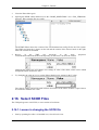
2.16.1. Lesson in changing the SCOE file ........................................................ 119
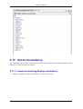
2.17. Check Consistency ........................................................................................ 124
2.17.1. Lesson in checking display consistency ................................................ 124
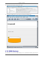
2.18. MDB Displays .............................................................................................. 131
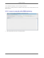
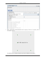
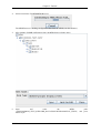
2.18.1. Lesson in using the editor MDB interfacing .......................................... 132
2.19. Quick Tutorial ............................................................................................... 145
USS User Manual
iv
2006-11-08 17:01
USS User Manual
2.19.1. Preparation ......................................................................................... 145
2.19.2. Editor Tutorial .................................................................................... 146
2.19.3. Executor Tutorial ................................................................................ 148
3. Editor ........................................................................................................................ 153
3.1. Introduction .................................................................................................... 153
3.2. The Editor Workspace ..................................................................................... 153
3.2.1. Arranging Views and Tab Windows ...................................................... 154
3.2.2. Editor Menus ....................................................................................... 157
3.3. Working with Displays .................................................................................... 160
3.3.1. Merging Displays ................................................................................. 161
3.3.2. Previewing Displays ............................................................................. 161
3.3.3. Target System and DQI Style ................................................................ 164
3.4. Working with Elements ................................................................................... 164
3.4.1. Adding and Deleting Elements .............................................................. 165
3.4.2. Editing Element Properties .................................................................... 166
3.4.3. Selecting Elements ............................................................................... 167
3.4.4. Basic Operations .................................................................................. 168
3.4.5. Zooming In and Out ............................................................................. 168
3.4.6. Aligning and Distributing Elements ....................................................... 169
3.4.7. Using the Grid ...................................................................................... 169
3.4.8. Grouping Elements ............................................................................... 169
3.4.9. Working with Depth ............................................................................. 170
3.4.10. Changing the Element Default Values .................................................. 170
3.5. Using The Symbol Library ............................................................................... 170
3.5.1. Pre-Defined Dynamic Symbols ............................................................. 171
3.5.2. Creating New Libraries and Symbols ..................................................... 172
3.6. Elements' Advanced Properties ........................................................................ 175
3.6.1. The Display ......................................................................................... 175
3.6.2. Label ................................................................................................... 175
3.6.3. Data Field ............................................................................................ 176
3.6.4. Command Button ................................................................................. 179
3.6.5. Command List ...................................................................................... 180
3.6.6. Navigation Button ................................................................................ 181
3.6.7. Graphs ................................................................................................. 182
3.6.8. Arc ...................................................................................................... 190
3.6.9. Polyline and Polygon ............................................................................ 190
3.6.10. Linear- and Elliptic- Tickmeter, Thermometer and Tankmeter ............... 191
3.6.11. Pipe, Valve and CheckValve ............................................................... 196
3.6.12. Input Field ......................................................................................... 197
3.6.13. File Chooser ....................................................................................... 197
3.6.14. Image ................................................................................................ 198
3.7. Data Sources ................................................................................................... 198
3.7.1. Data Source Dialog .............................................................................. 199
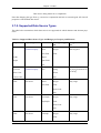
3.7.2. Supported Data Source Types ................................................................ 201
3.7.3. Dynamic Properties .............................................................................. 202
3.7.4. Expressions .......................................................................................... 202
3.8. Mission Database ............................................................................................ 207
3.8.1. Importing Displays from the MDB ........................................................ 207
3.8.2. Exporting Displays to the MDB ............................................................. 207
3.8.3. Adding a New Display to the MDB ....................................................... 207
3.8.4. Forced Import from MDB (revert) ......................................................... 208
3.8.5. Delete in MDB ..................................................................................... 208
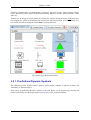
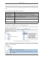
3.9. System Configuration Browser ......................................................................... 208
3.10. Working with Projects ................................................................................... 210
3.10.1. Synoptic Hierarchy ............................................................................. 210
3.10.2. Consistency Check ............................................................................. 210
3.11. Configuring the Editor ................................................................................... 211
USS User Manual
v
2006-11-08 17:01
USS User Manual
3.11.1. System Setting ................................................................................... 211
3.11.2. Preferences ........................................................................................ 211
3.11.3. View Settings ..................................................................................... 212
4. Executor .................................................................................................................... 213
4.1. Introduction .................................................................................................... 213
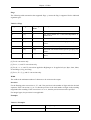
4.1.1. Configuring User Settings ..................................................................... 213
4.1.2. Exiting the Executor ............................................................................. 214
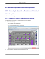
4.2. Monitoring and Control Configuration .............................................................. 214
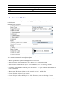
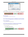
4.2.1. Connecting to System to be Monitored and Controlled ............................ 215
4.2.2. Disconnecting System to be Monitored and Controlled ........................... 216
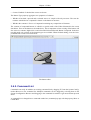
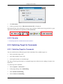
4.2.3. Switching Target for Commands ........................................................... 217
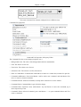
4.2.4. Checking Acquisition State ................................................................... 218
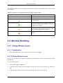
4.3. Window Handling ........................................................................................... 221
4.3.1. Saving Window Layout ........................................................................ 221
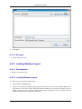
4.3.2. Loading Window Layout ...................................................................... 222
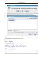
4.3.3. Loading Display from File System ........................................................ 223
4.3.4. Reloading Display from File System ...................................................... 224
4.3.5. Resizing Display Window ..................................................................... 225
4.3.6. Resetting Display Window to Default Size ............................................. 225
4.3.7. Navigating Display Hierarchy ............................................................... 226
4.3.8. Navigating to Home Display ................................................................. 227
4.3.9. Showing/Hiding the Toolbar ................................................................. 228
4.3.10. Closing Display .................................................................................. 228
4.3.11. Closing All Displays ........................................................................... 229
4.3.12. Closing Other Displays ....................................................................... 229
4.3.13. Toggling Tabbed Mode ....................................................................... 230
4.3.14. Undocking Windows .......................................................................... 230
4.3.15. Docking Windows .............................................................................. 231
4.4. Display Interaction .......................................................................................... 232
4.4.1. Showing Tooltip for Element ................................................................ 232
4.4.2. Showing Element Properties ................................................................. 233
4.4.3. Showing Display Properties .................................................................. 235
4.4.4. Copying Command to Clipboard ........................................................... 236
4.4.5. Copying Parameter Name to Clipboard .................................................. 237
4.4.6. Issuing Telecommand via Command Button .......................................... 237
4.4.7. Issuing Telecommand via Command List ............................................... 241
4.4.8. Finding Displays with Parameter References .......................................... 242
4.4.9. Finding Text in Display ........................................................................ 244
4.4.10. Showing Line Graph for Parameter Value History ................................ 245
4.5. Help ............................................................................................................... 246
4.5.1. Showing Display Help .......................................................................... 246
4.5.2. Getting Executor Version Information ................................................... 246
4.6. Miscellaneous ................................................................................................. 247
4.6.1. Print Preview ....................................................................................... 247
4.6.2. Printing Display ................................................................................... 249
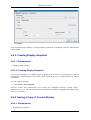
4.6.3. Creating Display Snapshot .................................................................... 250
4.6.4. Saving a Copy of Current Display ......................................................... 250
4.6.5. Configuring Status Display ................................................................... 251
4.6.6. Configuring Data Quality Indicators ...................................................... 252
5. Importing Foreign Display Formats ............................................................................. 254
5.1. Introduction .................................................................................................... 254
5.2. Importing PCS/PREP Displays ......................................................................... 254
5.3. Importing PWS/FWDU Displays ..................................................................... 254
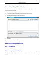
5.3.1. Extracting FWDU Displays from MDB ................................................. 255
5.3.2. Generating SCOE XML files ................................................................. 255
5.3.3. Converting XBM Images to PNG Format ............................................... 255
5.3.4. Converting the FWDU ASCII definition to USS Format ......................... 256
USS User Manual
vi
2006-11-08 17:01
USS User Manual
5.4. Importing GWDU Displays ............................................................................. 256
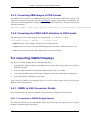
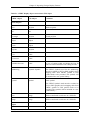
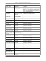
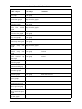
5.4.1. GWDU to USS Conversion Details ....................................................... 256
6. Localizing Displays For Different Languages .............................................................. 264
6.1. Introduction .................................................................................................... 264
6.2. Translation workflow ...................................................................................... 264
6.3. Generating skeletons with the Skeleton Generator ............................................. 264
6.4. Supported attributes ......................................................................................... 265
6.5. Format of Entry Keys ...................................................................................... 265
7. Reference .................................................................................................................. 267
7.1. Menue references for the executor .................................................................... 267
7.1.1. File Menue ........................................................................................... 267
7.1.2. Navigate Menue ................................................................................... 268
7.1.3. View Menue ........................................................................................ 268
7.1.4. Options Menue ..................................................................................... 268
7.1.5. Window Menue .................................................................................... 269
7.1.6. Help Menue ......................................................................................... 269
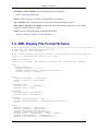
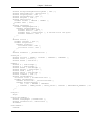
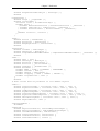
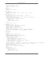
7.2. XML Display File Format Schema ................................................................... 270
A. Example USS Configuration in MCS Environment ..................................................... 282
A.1. USS Editor Parameter ..................................................................................... 282
A.2. USS Executor Parameter ................................................................................. 283
Glossary ........................................................................................................................ 285
References .................................................................................................................... 296
Alphabetical index ......................................................................................................... 297
USS User Manual
vii
2006-11-08 17:01
List of Tables
3.1. Taget systems and DQI style files ............................................................................. 164
3.2. Element Properties with "Default Capability" ............................................................ 170
3.3. Conversions ............................................................................................................ 177
3.4. Flags ...................................................................................................................... 178
3.5. Examples ................................................................................................................ 178
3.6. Supported Data Source Types and Ranges per Property and Element .......................... 201
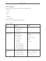
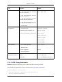
3.7. Operators ................................................................................................................ 203
3.8. Results of dragging TM/TC from the SCB ................................................................ 209
4.1. Indication of Acquisition Status for Status of Data Sources ........................................ 221
5.1. GWDU display object conversion to USS object ....................................................... 257
5.2. GWDU attributes conversion to USS properties ........................................................ 262
6.1. Supported attributes ................................................................................................. 265
USS User Manual
viii
2006-11-08 17:01
Chapter 1: Welcome to USS:
Installation and Getting Started
In this chapter we'll explain how to install USS, and where to find more detailed information if you
should encounter any problems during the installation. Next we'll explain how to adjust USS to the
target environment by configuring the system settings. As an example we'll show how to configure
the home display. And the last step in this chapter is the getting started part, in which we'll point you
in the direction where you can start with the editor and executor.
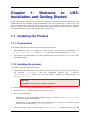
1.1. Installing the Product
1.1.1. Prerequisites
To install the USS product in the target environment make sure that:
1.
The distribution archive is available. For Linux systems, the archive has the filename ussx.y.z-linux-i586.tar.gz where x.y.z is the release version identifier (e.g., 1.4.0).
2.
The target environment fulfills the system requirements as specified in the INSTALL file of the
distribution archive.
1.1.2. Installing the product
To install USS into the target environment:
1.
Unpack the distribution archive into a directory on the target host or central file server. If the target directory is $basedir, then the distribution unpacks into a directory
$basedir/uss-x.y.z where x,y,z are version numbers. Change the working directory to
$basedir/uss-x.y.z.
Important
The installation path may not contain any whitespace!
2.
Read the README file for general and latest information.
3.
Read the INSTALL file for detailed installation instructions.
4.
Do one of the following:
• Change the $PATH environment variable settings to include $basedir/uss-x.y.z/bin
into the search path for executables.
• Alternatively, create symbolic links to the programs in the bin directory to a directory that is
already on the search path (e.g., /usr/local/bin).
5.
Check ownership of files. All files under $basedir/uss-x.y.z shall be owned by root. By
USS User Manual
1
2006-11-08 17:01
Chapter 1: Welcome to USS: Installation and Getting Started
default, USS does not create or modify files under $basedir. Therefore, it is possible to install
and use USS on a read-only mounted filesystem.
1.1.3. Installing platform independent version
Note! This section only applies, if you are using the platform idependent version of USS.
1.
Install USS as described in the section above.
2.
Locate the JRE or JDK used on your system. (See $JAVA_HOME environment variable)
3.
Copy the files from $basedir/share/fonts in to $JAVA_HOME/jre/lib/fonts if you are using
a JDK or into $JAVA_HOME/lib/fonts if you are using a JRE.
1.1.4. Integration with CGS
To integrate USS with CGS 6.3.1 or higher, the CGS Installer should be used. It does automatically
unpack the USS archives and changes some properties to meet the CGS needs. USS Editor and Executor are integrated in the top level user interfaces of CGS. Generation of XML SCOE files and export of displays from data base to file system is automatically done by CGS when required. USS displays stored in the mission data base are available through HLCL/UCL commanding and CGS screen
setups.
For further information refer to CGS User Manual 6.3.1, section 7.3.2.4.13 USS Displays.
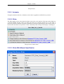
1.2. Configuring System Settings
After installation, the system settings should be configured to adjust USS to the target environment.
To configure the system settings, follow these steps:
1.
Open the file $basedir/uss-x.y.z/etc/uss.properties with a text editor.
2.
Read the comments in the configuration file and edit settings where necessary.
3.
Save the changed file. The new settings will be used the next time one of the USS applications is
started.
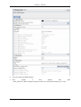
For settings in the uss.properties file that can also be set via the user interface (e.g. via properties dialog) the following rules apply: Settings made in the uss.properties file only define initial
defaults. Once they are changed in the UI, the UI settings have preference over the
uss.properties setting. This means that later changes in the uss.properties may be ignored.
The following explains the precedence of uss.config over uss.properties by explaining the
setting of uss.cmd.telecommanding and the various effects on the executor depending on where it is
set. Settings in uss.config have precedence over uss.properties. For example the installation
configuration is that the uss.cmd.telecommanding is set to false in uss.config. Changes to
uss.cmd.telecommanding in the running executor are also saved to uss.config. Changes to that
value in uss.properties while the executor isn't running has no impact on the executor's preferences, because of the already mentioned precedence of uss.config over uss.properties.
USS User Manual
2
2006-11-08 17:01
Chapter 1: Welcome to USS: Installation and Getting Started
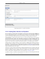
1.2.1. Configuring location of SCOE files
1.2.1.1. Prerequisites
• USS must be installed.
1.2.1.2. Configuring location of SCOE files
The location for the SCOE files can be set in uss.properties.
To configure the location of the SCOE files:
1.
Edit uss.properties file in $basedir/uss-x.y.z/etc/ with a text editor and set the corresponding
property uss.scoe.dir to the new location of the SCOE files.
Example given: In MCS the SCOE files usually are in $CGS_HOME/etc/mda/ccu/xml the the location can be set with:
• uss.scoe.dir = ${CGS_HOME}/etc/mda/ccu/xml
1.2.1.3. See also
• Configure system settings
1.3. Getting Started
USS consists of two major applications. The first one is the editor and the second is the executor. The
editor is the application for creating USS displays for later execution in the executor. The editor supports the definition of layout, composition and dynamic properties of synoptic displays. The executor
executes the displays which have been authored in the editor.
1.3.1. Starting the Editor
The editor is started via a shell script. Open a shell and enter uss-editor.sh. The editor will open
in a new window.
Tip
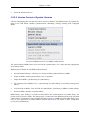
In MCS, the editor and executor can be started from the task selector menu.
For more options on how to start the editor, take a look into the section starting the executor. In that
chapter the starting via shell script is explained in more detail with lots of screenshots.
1.3.2. Starting the executor
USS User Manual
3
2006-11-08 17:01
Chapter 1: Welcome to USS: Installation and Getting Started
The executor is started via a shell script. Open a shell and enter uss-executor.sh. The executor
will open in a new window.
Tip
In MCS, the editor and executor can be started from the task selector menu.
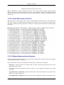
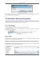
The executor offers a number of command line parameters. Use the --help option for getting help
on these:
uss-executor.sh --help
usage: uss-executor.[sh|bat] [OPTION]... [FILE]...
Start USS executor. If FILES are given, then load them as displays. OPTION
may be one or more of the following.
-a,--animate
animate displays for preview
-d,--default
start with the default layout (from last session)
-h,--help
print this text and exit
-l,--layout
load layout from file
-m,--mcs
start with a connection to mcs
-p,--project
sets project root for executor, overriding user
settings
-r,--remote
enable remote control
-s,--samplefile
start with sample file as dataprovider
-x,--home
sets home display for executor, overriding user
settings
USS User Manual
4
2006-11-08 17:01
Chapter 2: Tutorial
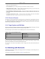
2.1. Introduction
This tutotial is put together of a seies of lessons, going through some of the basic and advanced editing of the USS editor, as well as some advanced topics covering editing external to the USS Editor.
Lessons in creating command elements (9) and navigation elements (10) are made as a continous extended lessons, but can with slight modification be used seperately.
Lesson topics:
1.
Installation of USS
2.
Usage of the USS Editor
3.
Creation of displays
4.
Import of display of non-USS format
5.
Major GUI elements
6.
Howto Edit DQI style files
7.
Creation nof ASCII displays
8.
Making a graph display
9.
Creation of displays with commands
10. Creation of displays with navigation
11. Adding symbols to displays
12. Creation of new symbols and symbol libraries
13. Creation of displays with advanced elements
14. Changing the USS property file
15. Changing the USS Editor SCOE file
16. Checking Consistency of Displays
17. MDB display actions
18. Quick tutorial
2.2. Installation of USS package
For Prerequisites for installation and other information on installation of USS, see install USS
USS User Manual
5
2006-11-08 17:01
Chapter 2: Tutorial
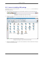
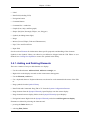
2.2.1. Lesson in installing USS package
Assumption: The archive has the filename uss-2.6.0-linux-i586.tar.gz is used with this tutorial in home directory.
1.
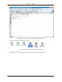
On the desktop find the Konquerer icon in the task bar, and click on it to start the file-browser.
Konquerer. is normally in the quick start icon bar
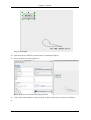
2.
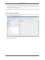
Konquerer normally opens in the home folder of the current user, click the release info file, to
read the release info.
Konquerer showing the content of the user home folder
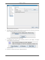
3.
Konquerers embedded text viewer, shows release information. Click the back-button in konquerer to go back to the home folder.
USS User Manual
6
2006-11-08 17:01
Chapter 2: Tutorial
Release information whown in Konquerer embedded viewer
4.
Find the USS package, compressed folder.
For Linux USS is delievered as a Gzipped, tar archive
5.
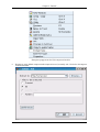
Right-click the compressed archive and select 'Extract here' form popup menu.
USS User Manual
7
2006-11-08 17:01
Chapter 2: Tutorial
Konquerer popup menu for USS compressed archive
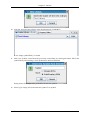
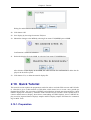
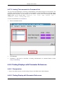
6.
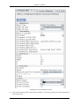
Konquerer open default compression/decompression tool, normally Ark. Click ok to decompress
in the home folder.
USS User Manual
8
2006-11-08 17:01
Chapter 2: Tutorial
Ark compression tool
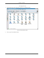
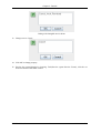
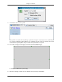
7.
The decompression of the USS archive generates a uss installation folder.
Selected USS installation folder
8.
Click to open USS installation folder.
USS User Manual
9
2006-11-08 17:01
Chapter 2: Tutorial
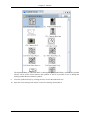
Konquerer showing the contents of USS installation folder
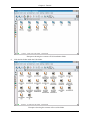
9.
Click the bin-folder inside the USS-folder.
Konquerer showing the contents of the uss-bin-folder
USS User Manual
10
2006-11-08 17:01
Chapter 2: Tutorial
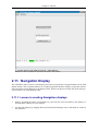
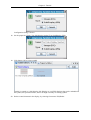
10. Find the uss-editor.sh file in the bin-folder.
Selected uss-editor.sh file
11. All shell scripts, i.e. files ending/with extension 'sh' are launch files for the USS applications for
UNIX. Likewise all the batch-scripts, i.e. files ending 'bat' are launch files for the USS applications for MS Windows. Click the uss-editor.sh file, and the USS Editor starts.
Start splash picture of the USS Editor
2.3. Using the Editor GUI
2.3.1. Introduction
This lesson will introduce the usage of the basic user interface of the USS Editor. You shall work with
the following subjects:
1.
Docking mechanishm of editor panels
2.
Tool views of the editor
3.
Printing of displays
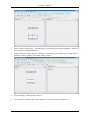
2.3.2. Docking mechanishm of editor panels
The USS Editor features a docking framework for tool- and display views. By default views are
opened as frames inside the main editor application. Small docking control icons allows you to:
1.
Undock/Minimize/Close - when view is docked, ie. inside main window
2.
Dock/Close - when view is undocked, ie. appears in a seperate window
USS User Manual
11
2006-11-08 17:01
Chapter 2: Tutorial
3.
Undock/Minimize/Maximize/Close - when views are collected in tabs (multiple views in tabs)
2.3.2.1. Lesson in docking mechanishm of editor panels
1.
Start by openning the editor via installed icon.
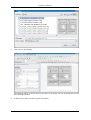
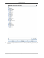
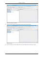
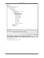
Editor started with default empty display created, three tool views open: Synoptic Hierarchy,
Property Editor and Symbol Library. This is an example of start-up layout, the editor saved basic
layout and which tools are open from previous editor closing.
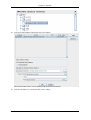
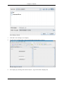
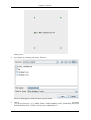
2.
Undock the view called Property Editor by clicking with left-mouse-button on the undock icon
for the Property Editor View. The Property Editor will undock and still function as part of the editor application.
USS User Manual
12
2006-11-08 17:01
Chapter 2: Tutorial
The Property Editor is undocked and can be moved around independently of the main application, on computers with multiple screens, the view can be moved to another screen to better take
advanced of the setup.
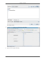
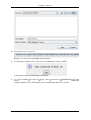
3.
Re-dock the Property Editor by clicking with left-mouse-button on the dock icon in the undocked
view. The Property Editor will dock again.
USS User Manual
13
2006-11-08 17:01
Chapter 2: Tutorial
The Property Editor is docked again and can be moved around inside the main application. The
view will when moved (click and hold left-mouse-button) dock in different position or on top of
other views.
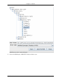
4.
Close Property Editor and Symbol Library views by clicking closing their common tab-view.
The editor will warn you of the closing of multiple views.
This concludes the lesson in the USS Editors docking mechanishm.
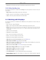
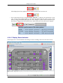
2.3.3. Tool views of the editor
The USS Editor features a multitude of tool-views, default views are opened in their latest position
and size. The editor menu gives the easiest access to the tool-views.
1.
Property Editor, show current selected item's propeties and allow to edit them if they are editable
2.
Consistency Checker, show the results of latest consistency check for current display, information, warnings and errors are displayed
3.
Synoptic Hierarchy, show all open displays, as well as the content of the USS project-folder, and
can be used for easy navigation, when multiple displays are open
USS User Manual
14
2006-11-08 17:01
Chapter 2: Tutorial
4.
Symbol Library, show the currently open library and allows to change library and select symbols
5.
System Configuration Browser, show the content from the currently SCOE file, and can be used
for easily adding End-items to displays
6.
View Settings, show display settings like grid configuration etc. for the currently selected display
view
2.3.3.1. Lesson in tool views
1.
Start by openning the editor via installed icon, when open close all tool-views and open Property
Editor from menu: Views|Property Editor.
Editor started with default empty display created, property editor showing (layout might differ).
2.
Undock the Property Editor.
USS User Manual
15
2006-11-08 17:01
Chapter 2: Tutorial
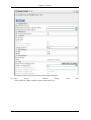
The Property Editor is undocked and it is showing the open display settings. Showed for a display is the following categories:
a.
Appearance - Basic appearance of display like background colours
b.
Behaviour - Only behaviour setting for display
c.
Context - Information about displays context and references
d.
Dimensions - Dimensions of display: width and height
USS User Manual
16
2006-11-08 17:01
Chapter 2: Tutorial
e.
Information - Description and title information
f.
Log - Logging information for simple revision control
3.
Close the Property Editor by clicking the close icon in the undocked view.
4.
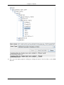
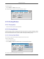
Open the Synoptic Hierarchy from menu: Views|Synoptic Hierarchy and undock it.
The Synoptic Hierarchy is undocked and it is showing the open display selected, as well as the
displays (not-opened) saved in the USS project-folder. The Synoptic Hierarchy can be used to select displays and elements within, as well as it easily gives access to the project displays.
5.
Close the Synoptic Hierarchy by clicking the close icon in the undocked view.
6.
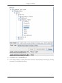
Open the System Configuration Browser from menu: Views|System Configuration Browser and
undock it.
USS User Manual
17
2006-11-08 17:01
Chapter 2: Tutorial
The System Configuration Browser is undocked and it is showing the content of the SCOE file,
different OPS and Path views exist as well as categories:
a.
Onboard Telemetry
b.
Ground Telemetry
c.
Onboard Commands
d.
Ground Commands
e.
Onboard Events
f. Ground Events
The System Configuration Browser can be used to SCOE content to the displays without hard
configuration task.
7.
Close the System Configuration Browser by clicking the close icon in the undocked view.
8.
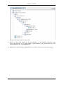
Open the Symbol Library from menu: Views|Symbol Library and undock it.
USS User Manual
18
2006-11-08 17:01
Chapter 2: Tutorial
The Symbol Library is undocked and it is showing the open symbol library selected. The Symbol
Library can be used to select libraries and symbols as well as it provides access to adding and
editing symbol libraries and their symbols.
9.
Close the Symbol Library by clicking the close icon in the undocked view.
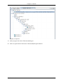
10. Open the View Settings from menu: Views|View Settings and undock it.
USS User Manual
19
2006-11-08 17:01
Chapter 2: Tutorial
The View Settings is undocked and it is showing the open view settings of the display selected.
The View Settings can be used to alter the grid and appearance of the display in the editor. It has
the same layout and features as the Property Editor Showed for a display is the following categories:
a.
Grid - Basic appearance of Grid in the display view, as well as behaviour off elements when
they are being moved or resized
b.
Zoom - Zoom settings
11. Close the View Settings by clicking the close icon in the undocked view.
This concludes the introduction to the editors tool-views.
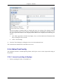
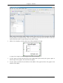
2.3.4. Editor Print Facility
The USS Editor features a standard printing feature, which gives access to basic layout and scaling of
the printout.
2.3.4.1. Lesson in printing of displays
1.
Start by openning the editor via installed icon.
USS User Manual
20
2006-11-08 17:01
Chapter 2: Tutorial
Editor started with default empty display created.
2.
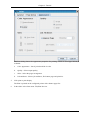
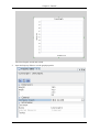
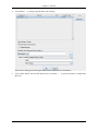
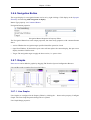
In the editor select from menu: File|Print
The editors print dialog opens with default printer selected. The General tab the following print
USS User Manual
21
2006-11-08 17:01
Chapter 2: Tutorial
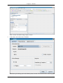
properties can be selected:
3.
a.
Name - Selects Printer
b.
Properties - Properties for printer if available
c.
Print To File - Check if print should go to a post-script file
d.
Print Range - Select the range of pages to print
e.
Copies - Number of copies and how to handle multiple copies
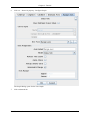
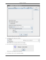
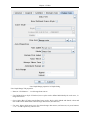
Click the tab: Page Setup to show further properties
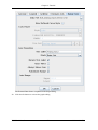
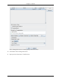
The Print dialog shows the Page Setup properties for printing, which are descripped below:
4.
a.
Size - Selects Paper size in printer
b.
Source - Select paper source, ie. tray in printer
c.
Orientation - How the print is oriented on the paper
d.
Margins - Margins on the paper
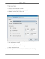
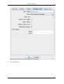
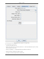
Click the tab: Appearance to show further properties and check properties: Banner Page
USS User Manual
22
2006-11-08 17:01
Chapter 2: Tutorial
The Print dialog shows the Appearance properties for printing, which are descripped below, if
available:
5.
a.
Color Appearance - Sets if print should be in color
b.
Quality - Select output quality
c.
Sides - Select the pages arrangement
d.
Job Attributes - Selects job attributes, like banner page and priorities
Click print to print display.
The Print is printed on the configured printer with a banner page first.
6.
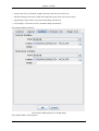
In the editor select from menu: File|Print Preview
USS User Manual
23
2006-11-08 17:01
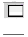
Chapter 2: Tutorial
The Print Preview dialog shows the expected print layout.
This concludes the lesson in the USS Editors printing mechanishm.
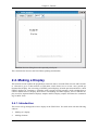
2.4. Making a Display
This tutorial section explains the preparations needed in order to run both USS executor and USS editor. After this it gives a short tutorial on USS editor, which shows how to create a new ground ops
(Satmon like) display, the converting of GWDU ground displays in batch operation and how to check
GWDU displays for consistency. It finishes with a tutorial on USS executor, which explains how to
connect and disconnect a display; shows direct commanding of FWDU displays, shows a GWDU display aswell as imported Satmon displays samples and PCS display samples and shows the commanding via MCS Tools.
2.4.1. Introduction
This lesson will go through the a basic display in the USS Editor. You shall work with the following
subjects:
1.
Making of a display
2.
Adding elements
USS User Manual
24
2006-11-08 17:01
Chapter 2: Tutorial
3.
Previewing a display
2.4.2. Making display
The USS Editor can make display in the USS xml format via its GUI.
2.4.2.1. Lesson in making a display
1.
Start by openning the editor via installed icon.
Editor started with default empty display created, three tool views open: Synoptic Hierarchy,
Property Editor and Symbol Library. This is an example of start-up layout, the editor saved basic
layout and which tools are open from previous editor closing.
2.
Add a new display by selecting from menu: File|New
A new display is opened.
3.
Add a label by choosing from menu: Element|Add|Label. Click on label and edit text of label and
resize the label by pulling the corner of the label.
The New display has a label with your added text.
USS User Manual
25
2006-11-08 17:01
Chapter 2: Tutorial
4.
If Property Editor is not open, open it by choosing: Views|Property Editor
Property Editor Open
5.
In the Property Editor check the Label Text Autosize.
The Label changes text size to match the size of the label.
6.
Click on the in the display area outside the label area
Display is selected, and Property Editor shows the properies of the display.
7.
Undock the Property Editor and edit the following properties by clicking in the field for the properties int Property Editor and editing:
a.
Background color: Click button: '...' and add from color dialog a light blueish color.
b.
Check the property: Show Execute Button
c.
Fill in the properties in the category: Information
USS User Manual
26
2006-11-08 17:01
Chapter 2: Tutorial
USS User Manual
27
2006-11-08 17:01
Chapter 2: Tutorial
The Property Editor shows the edited properties for the display.
8.
Add a Tankmeter, a Telecommand button and a Rectangle from the editor menu: Element|Add|...
Display contains a Label, Tankmeter, Telecommand button and a Rectangle.
9.
Click the added Tankmeter to select it, edit it properties in the Property Editor to match:
Result after editing. TankMeter changes with it properties
Tip
In the Property Editor, the property: Data Source containts a button: '...', which gives access to
the data source editing dialog
10. Click the added Telecommand to select it, edit it properties in the Property Editor to match:
USS User Manual
28
2006-11-08 17:01
Chapter 2: Tutorial
Result after editing. Telecommand has changed.
Tip
In the Property Editor, the property: Command containts a button: '...', which gives access to
the command editing dialog
USS User Manual
29
2006-11-08 17:01
Chapter 2: Tutorial
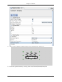
11. Click the added Rectangle to select it, edit it properties in the Property Editor to match:
Display is edited.
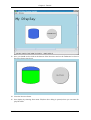
12. Now you should preview you created display to get a better feel for it appearance and test its behaviour. Select from menu: Tools|Previwer ... Display is opened in the previewer frame:
USS User Manual
30
2006-11-08 17:01
Chapter 2: Tutorial
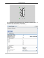
13. Now you should use the slider at the bottom of the Previewer and see the Tankmeter level move
Previewer frame snap-shoot:
14. Close the Previwer frame.
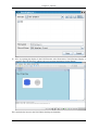
15. Save display by selecting from menu: File|Save Save dialog is opened, where you can enter display file-name
USS User Manual
31
2006-11-08 17:01
Chapter 2: Tutorial
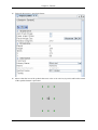
16. Now try opening the display in the USS Executor select from menu: Tools|Executor Display is
opened in the USS Executor, which is the real execution application for the display:
This concludes the lesson in the USS Editors docking mechanishm.
USS User Manual
32
2006-11-08 17:01
Chapter 2: Tutorial
2.5. Import existing displays
The USS Editor can import displays from the following formats:
1.
Old USS display versions (1, 2, 3) mostly used during development
2.
FWDU displays
3.
GWDU displays
4. NASA, PCS displays
Imported display definitions become USS displays meaning that they will have the USS XML-based
file format and the .uss file extension. The imported displays cannot be exported back into the legacy
display formats.
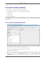
2.5.1. Lesson in importing a display
1.
Start by openning the editor via installed icon.
Editor started with default empty display created, three tool views open: Synoptic Hierarchy,
Property Editor and Symbol Library. This is an example of start-up layout, the editor saved basic
layout and which tools are open from previous editor closing.
2.
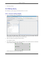
Open / import a GWDU display by selecting from menu: File|Open
The file open dialog is now open.
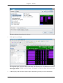
3.
Browse via the open dialog to the display: CMD_QUEUES.gwdu Remember to change File of
Type
to
All
Files
CMD_QUEUES.gwdu
can
be
found
under
path:
<USS_INSTALL_DIR>/examples/import/gwdu/msc/APM/COL_CC/MCS_OPS/CONFIG/SYN
OPTICS/MCS
USS User Manual
33
2006-11-08 17:01
Chapter 2: Tutorial
The import display selected, preview shown.
4.
Click open to open display.
The imported display is shown shown in the editor, the import process is seamless and a convertion is done between GWDU and USS format. The display can now be edited, and saved to the
USS display format.
5.
In the Property Editor check the display import information given by the Source information
USS User Manual
34
2006-11-08 17:01
Chapter 2: Tutorial
6.
Close the imported GWDU display.
7.
Now
import
a
PCS
display
with
<USS_INSTALL_DIR>/examples/import/pcs/xml/Col_Cabin_FanAssemblies_ACT.xml
USS User Manual
35
path:
2006-11-08 17:01
Chapter 2: Tutorial
8.
Click open to open display.
The imported display is shown shown in the editor. The display can now be edited and saved to
the USS display format.
9.
In the Property Editor check the import information.
USS User Manual
36
2006-11-08 17:01
Chapter 2: Tutorial
The Property Editor shows the properties for the imported display.
10. Now
import
a
Satmon
display
<USS_INSTALL_DIR>/examples/import/satmon/1092.xml
USS User Manual
37
with
path:
2006-11-08 17:01
Chapter 2: Tutorial
11. Click open to open display.
The imported display is shown shown in the editor. The display can now be edited and saved to
the USS display format.
12. In the Property Editor check the import information.
USS User Manual
38
2006-11-08 17:01
Chapter 2: Tutorial
The Property Editor shows the properties for the imported display.
This concludes the lesson in the USS Editors import mechanishm. The USS Editor and Executor use
the same import mechanishm.
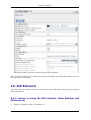
2.6. GUI Elements
This lesson takes you through the major GUI elements of the USS Editor namely the View Settings
and the Preferences.
2.6.1. Lesson in using the GUI elements (View Settings and
Preferences)
1.
Start by openning the editor via installed icon.
USS User Manual
39
2006-11-08 17:01
Chapter 2: Tutorial
Editor started with default empty display created, three tool views open: Synoptic Hierarchy,
Property Editor and Symbol Library. This is an example of start-up layout, the editor saved basic
layout and which tools are open from previous editor closing.
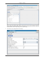
2.
Close all tool views and open the View Settings
USS User Manual
40
2006-11-08 17:01
Chapter 2: Tutorial
A Display is open with the View Settings showing. The View Settings are not saved with the displays, the properties are non-persistent and only for viewing in the Editor. They provide a help
when editing.
3.
Change the grid colour to draw style to yellow and the draw style to Lines.
The Display grid colour change as well as the draw style, the grid is now fully drawn.
4.
Now change the following properties:
a.
grid spacing to 50/20 (Horizontal/Vertical)
b.
set the Zoom factor to 200 %
c.
grid draw tickness to 2 pixels
USS User Manual
41
2006-11-08 17:01
Chapter 2: Tutorial
5.
Undock the View Settings and to get a better view of the settings changed.
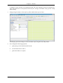
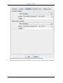
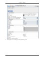
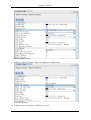
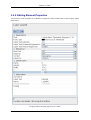
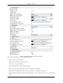
Walk-through of the Editor Preferences
1.
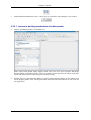
Open the editor preferences by selecting from menu: Edit|Preferences.
USS User Manual
42
2006-11-08 17:01
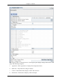
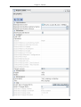
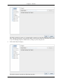
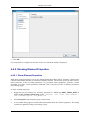
Chapter 2: Tutorial
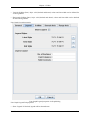
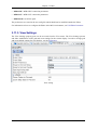
The Editor preferences opens, it is arranged after categories (to the left) and each category contains a group of properties. No properties change in the system before the OK-button is pressed,
so you can change properties without effect, as long as you do not press ok.
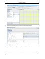
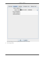
2.
Click on the Project category
The project category contains the following properties:
USS User Manual
43
2006-11-08 17:01
Chapter 2: Tutorial
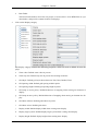
a.
Root Folder
The Root Folder defines where the uus-project is located, that is were MDB files are synchronized to, and provide common location for displays.
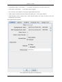
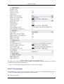
3.
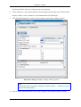
Click on the Display category
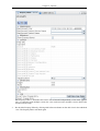
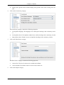
The display category contains the following properties, which are used as default for new displays:
a.
Zoom value: Default zoom value in percent
b.
Zoom step size: Default step size in percent for zooming in and out.
c.
Grid Style: Default grid style choose between: Non, Dots, Dashed, Lines
d.
Grid spacing width: Default grid spacing width in pixels
e.
Grid spacing height: Default grid spacing height in pixels
f.
Grid snap on resize policy: Default behaviour of snapping when resizing an element in a
display
g.
Grid snap on move policy: Default behaviour of snapping when moving an element in a display
h.
Grid draw tickness: Default grid tickness in pixels
i.
Grid draw colour: Default grid colour
j.
Display width: Default display width when creating anew display
k.
Display target system: Default display target system when creating anew display
l.
Display height: Default display height when creating anew display
USS User Manual
44
2006-11-08 17:01
Chapter 2: Tutorial
m. Display back ground colour: Default display back-ground colour when creating anew display
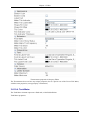
4.
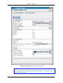
Click on the Consistency category
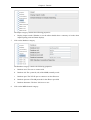
The consistency category contains the following properties:
5.
a.
Used OpNom language: The language to use while spell checking in the consistency checker
b.
Used OpNom check: The OpNom standard to use while checking in the consistency checker
c.
Run OpNom check: Wether or not to run OpNom checking in the consistency checker
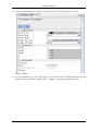
Click on the Data Source category
The Data Source category contains the following properties:
6.
a.
Context List: The list of contexts to be available in the Editor
b.
Context default: The default context to use from the context list
Click on the Import category
USS User Manual
45
2006-11-08 17:01
Chapter 2: Tutorial
The Import category contains the following properties:
a.
7.
Display import results: Whether or not the editor should show a summary of results when
import/opening external format displays
Click on the Database category
The Database category contains the following properties:
8.
a.
Database user: The user to connect with
b.
Database sid: The system id (sid) of the MDB, normally oracle
c.
Database port: The TCP/IP port to connect to on the dB-server
d.
Database password: The dB passwod for the dB user specified
e.
Database hostname: The host / db-Server to use
Click on the MDB-General category
USS User Manual
46
2006-11-08 17:01
Chapter 2: Tutorial
The MDB-General category contains the following properties:
9.
a.
Use CDU: Whether or not to use CDU (contra CCU)
b.
System Version: System verion number
c.
System mission: System mission setting
d.
System element config: System element configuration
Click on the MDB-CDU category
The MDB-CDU category contains the following properties:
a.
Cu version: The CU version to use with CDU
b.
Cu test version: The CU test version to use with CDU
c.
Cu revision: The CU revision to use with CDU
d.
Cu path: The CU path to use with CDU
e.
Cu issue: The CU issue to use with CDU
f.
Cu instance: The CU instance to use with CDU
g.
Cu domain: The CU domain to use with CDU
10. Click on the MDB-CCU category
USS User Manual
47
2006-11-08 17:01
Chapter 2: Tutorial
The MDB-CCU category contains the following properties:
a.
Cu path: The CU path to use with CCU
b.
Cu name: The CU name to use with CCU
c.
Cu version: The CU version to use with CCU
d.
Cu issue: The CU issue to use with CCU
e.
Cu revision: The CU revision to use with CCU
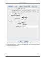
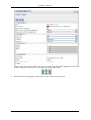
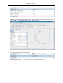
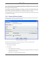
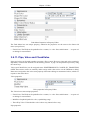
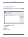
11. Click on the MDB-SCOE category
The MDB-SCOE category contains the following properties:
a.
SID: The System Id (SID) of the SCOE to use
b. File path: The File path to the SCOE file
Shown in the category is also the SCOE internal CU version.
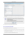
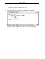
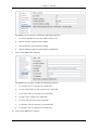
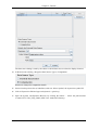
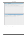
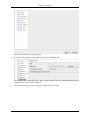
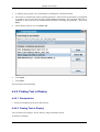
12. Click on the browse button to change SCOE file
USS User Manual
48
2006-11-08 17:01
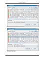
Chapter 2: Tutorial
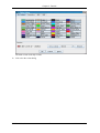
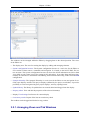
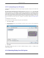
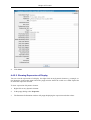
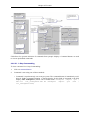
Here the SCOE file can be selected, if you change it the System Configuration Browser will reload with the new information.
This concludes the lesson in the USS Editors preferences. Normally these settings are preset delivered
from the system administrator.
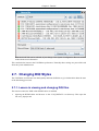
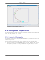
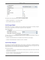
2.7. Changing DQI Styles
The USS Editor and Executor use Data Quality Indicator definition to give information about the state
of the data being processed.
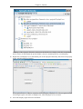
2.7.1. Lesson in viewing and changing DQI files
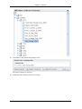
The lesson assumes the XML editor KXML-editor is installed.
1.
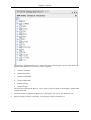
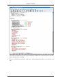
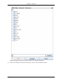
Opening the KXML-editor and browser to the >USS_INSTALL</etc directory. Here open the
file: mcs_dqistyle.xml
USS User Manual
49
2006-11-08 17:01
Chapter 2: Tutorial
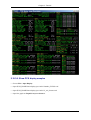
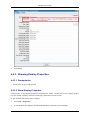
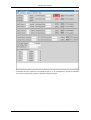
The KXML-Editor shows the content of the xml-formatted DQI file for the MCS target system.
The XML tree hierarchy is shown on the left and the content of the selected node on the right,
where the content can be edited.
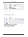
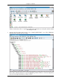
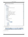
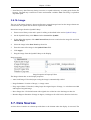
2.
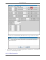
Browse in the XML tree hierarchy to the node: AcquisitionStatus and select it to show the content.
USS User Manual
50
2006-11-08 17:01
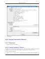
Chapter 2: Tutorial
Changing the values here will change the states used in the Editor Consistency Checker for the
MCS target system.
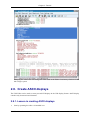
2.8. Create ASCII displays
The USS Editor can be used to create pure ASCII displays in the USS display format. ASCII display
contains only character based elements.
2.8.1. Lesson in creating ASCII displays
1.
Start by openning the editor via installed icon.
USS User Manual
51
2006-11-08 17:01
Chapter 2: Tutorial
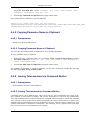
Editor started with default empty display created, three tool views open: Synoptic Hierarchy,
Property Editor and Symbol Library. This is an example of start-up layout, the editor saved basic
layout and which tools are open from previous editor closing.
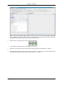
2.
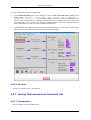
Add a label by selecting in the menu: Element|Add|Label
A text-label is created in the new display.
3.
Make four more labels and select them all by using the keyboard combination: CTRL+A
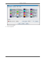
4.
In the Property Editor click to edit the colour and click '...' button to open colour dialog. Select
tab: RGB and choose the green colour: Red: 6, Green: 152, Blue: 6
USS User Manual
52
2006-11-08 17:01
Chapter 2: Tutorial
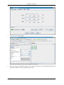
5.
Click Ok to the colour dialog.
The colours of all the label fonts are changed to a dark green.
6.
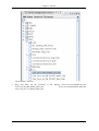
Open the System Configuration Browser and find in the OPS View for Onboard Telemetry, the
parameter \EPM\Gen_Com_AFS_RS485_Int_Stat
USS User Manual
53
2006-11-08 17:01
Chapter 2: Tutorial
The end-item is selected.
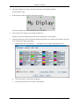
7.
Drag and Drop all the end-items to the display: Gen_Com_AFS_RS485_Int_Stat
Gen_Com_Int_SM_RS485_Main_Stat
Gen_Com_Int_SM_RS485_Red_Stat
Gen_Com_Int_VU_RS485_Main_Stat
USS User Manual
54
2006-11-08 17:01
Chapter 2: Tutorial
The end-items are added as four label/data-field pairs
8.
Select the four labels by hold keyboard key: CTRL and left-click with mouse on labels.
Four labels are selected.
9.
Align the labels to their common left, by selecting form menu: Element|Align|Vertical Left
10. Unselect the labels by left-clicking with mouse on the display back-ground
11. Select the four fields by hold keyboard key: CTRL and left-click with mouse on labels.
USS User Manual
55
2006-11-08 17:01
Chapter 2: Tutorial
Four fields are selected.
12. Align the fields to their common left, by selecting form menu: Element|Align|Vertical Left
Four fields are aligned
13. Use the magnifying glass with a + in it, to zoom the display, to have a better look at the result
USS User Manual
56
2006-11-08 17:01
Chapter 2: Tutorial
Display zoomed
14. Select the four labels added from the System Configuration Browser and Open the Property Editor. In the Property Editor change the font colour to same as the previous labels.
Label colours change
USS User Manual
57
2006-11-08 17:01
Chapter 2: Tutorial
15. Click on display back-ground (where there are no elements)
16. In the Property Editor select the Background colour of the display and change in to Black.
Display background is now black.
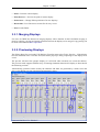
2.9. Making a Graph Display
The USS Editor can be used to create displays containing Graph of various kinds in the USS display
format. Graphs can be used to show larger data-sets in a more intuitive way.
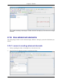
2.9.1. Lesson in creating Graph displays
1.
Start by openning the editor via installed icon.
USS User Manual
58
2006-11-08 17:01
Chapter 2: Tutorial
Editor started with default empty display created, three tool views open: Synoptic Hierarchy,
Property Editor and Symbol Library. This is an example of start-up layout, the editor saved basic
layout and which tools are open from previous editor closing.
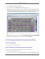
2.
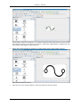
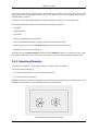
Make a Line Graph by selecting from menu: Element|Add|Line Graph
A empty Line Graph is made in the upper left of the new display.
3.
Use the mouse and left-click and drag on the right-bottom pick-control point (green square in
bottom-right of line graph). This will resize the graph.
4.
Use the mouse and left-click (and hold) in the middle of the graph and move the graph to the
middle of the display.
USS User Manual
59
2006-11-08 17:01
Chapter 2: Tutorial
The Line Graph is moved and resized.
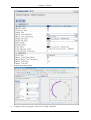
5.
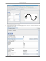
Open the Property Editor to see the graph properties.
USS User Manual
60
2006-11-08 17:01
Chapter 2: Tutorial
6.
Click on ...-button in property: Configure Graph.
The Graph Dialog opens for the Line Graph.
7.
Click on domain tab
USS User Manual
61
2006-11-08 17:01
Chapter 2: Tutorial
The Graph Dialog shows the domain tab for the Line Graph
8.
Click on gridline tab
USS User Manual
62
2006-11-08 17:01
Chapter 2: Tutorial
The Graph Dialog shows the grid line properties tab for the Line Graph
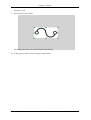
9.
Change the horizontal and vertical grid colours to Brown from My Colours and click OK-button
USS User Manual
63
2006-11-08 17:01
Chapter 2: Tutorial
Grid colour are updated.
10. Click on legend tab
USS User Manual
64
2006-11-08 17:01
Chapter 2: Tutorial
The Graph Dialog shows the legend properties tab for the Line Graph
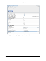
11. Click on general tab
USS User Manual
65
2006-11-08 17:01
Chapter 2: Tutorial
The Graph Dialog shows the general properties tab for the Line Graph
12. In the general tab click the ...-button to open the Background colour selection dialog and select
under My Colors the colour black
USS User Manual
66
2006-11-08 17:01
Chapter 2: Tutorial
The black colour under My Colours
13. Click ok to the colour dialog
USS User Manual
67
2006-11-08 17:01
Chapter 2: Tutorial
Background colour is now set to be used in the Line Graph
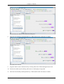
14. Goto the range-tab and click the ...-button for the property: Data-Set
USS User Manual
68
2006-11-08 17:01
Chapter 2: Tutorial
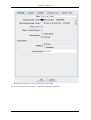
The Data Source Dialog is open. The dialog is used in the editor for all data source configuration
for elements.
15. Click the Add-button to add a new data source
USS User Manual
69
2006-11-08 17:01
Chapter 2: Tutorial
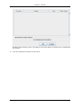
The Data Source Dialog add a new external data source.
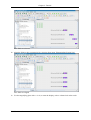
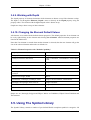
16. Under the details for the External Data Source click the ...-button to open the System Configuration Browser.
USS User Manual
70
2006-11-08 17:01
Chapter 2: Tutorial
17. In the System Configuration Browser browse to the following: \BLB\Analog_Input_Section_Fail
and select it
USS User Manual
71
2006-11-08 17:01
Chapter 2: Tutorial
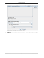
18. Click the Change-button followed by the Close-button
The External Data Source is now updated with the SCOE information.
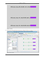
19. Click the Ok-button to activate the data-source editing
USS User Manual
72
2006-11-08 17:01
Chapter 2: Tutorial
The External Data Source is updated in the Graph dialog.
20. Click the Ok-button to activate the graph editing
USS User Manual
73
2006-11-08 17:01
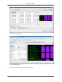
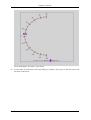
Chapter 2: Tutorial
The graph in the display is now updated to match the configuration.
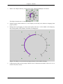
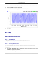
21. To Preview the graph: Select from menu: Tools|Previewer
USS User Manual
74
2006-11-08 17:01
Chapter 2: Tutorial
The line graph is previewed.
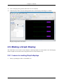
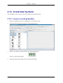
2.10. Create Commanding Display
The USS Editor can be used to create commanding displays in the USS display format.
2.10.1. Lesson in creating Commanding displays
1.
Start by openning the editor via installed icon.
USS User Manual
75
2006-11-08 17:01
Chapter 2: Tutorial
Editor started with default empty display created, three tool views open: Property Editor.
2.
Open the System Configuration Browser.
USS User Manual
76
2006-11-08 17:01
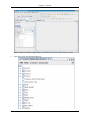
Chapter 2: Tutorial
The System Configuration Browser is shown.
3.
Shift the System Configuration Browser to OPS View Ground Commands, using the view selector on the right.
4.
Browse to the End-item \Cancel_Arch_Retrieval and select it.
5.
Use the mouse and left-click (and hold) on the end-item and drag it to the open display.
A telecommand button is made in the display with text Cancel_Arch_Retrieval.
6.
Browse to the End-item \Downlink_File and select it.
7.
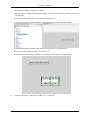
Use the mouse and left-click (and hold) on the end-item and drag it to the open display.
8.
Use the keyboard key combination: CTRL + A , to select all.
USS User Manual
77
2006-11-08 17:01
Chapter 2: Tutorial
All created display elements from the drag-and-drop operations are selected.
9.
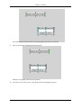
Choose from menu: Element|Align|Vertical Left
Elements are aligned to the left-most position.
10. Left-click to select the Cancel_Arch_Retrieval Telecommand (top-most).
USS User Manual
78
2006-11-08 17:01
Chapter 2: Tutorial
Telecommand selected.
11. Open the Property Editor.
USS User Manual
79
2006-11-08 17:01
Chapter 2: Tutorial
Properties of Telecommand is shown
12. Click in the Property Editor on the buuton with text: Cancel_Arch_Retrieval for the property Released Label Text.
USS User Manual
80
2006-11-08 17:01
Chapter 2: Tutorial
Dialog with changable text is shown
13. Change text to: Cancel
14. Click OK to change property.
15. Preview the created display by choosing: Tools|Preview (opens Preview Frame), click the created telecommand with label: Cancel
USS User Manual
81
2006-11-08 17:01
Chapter 2: Tutorial
Previewer shows simulated command execution at the bottom.
2.11. Navigation Display
The USS Editor can be used to create displays that can be navigated by navigation-buttons in the USS
display format. The navigation-buttons are complex hyperlinks between displays, using their relative
path (navigation cannot happen on the display itself). Pictures in this lesson show the result from previous lesson as one of the displays used.
2.11.1. Lesson in creating Navigation displays
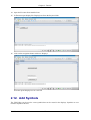
1.
Start by openning the editor via installed icon, close all tool-views and make a new display, so
that the editor contains two new displays.
2.
Arrange the displays by dragging them (left-click-hold on display-tab), so that both are visible at
the same time.
USS User Manual
82
2006-11-08 17:01
Chapter 2: Tutorial
3.
Make a label in each display. - Select display by left-clicking on display-background - Make a label from menu: Element|Add|Label
4.
Change label-text in first display to Display 1 and Display 2 for label-text in second display. Double left-click on label to start inline editing of label.
5.
Click on Display 1 background to select it.
6.
Save display by selecting from menu: 'File|Save'. Type in file name: 'Display1.uss'
USS User Manual
83
2006-11-08 17:01
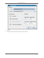
Chapter 2: Tutorial
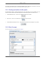
Save dialog is shown.
7.
Click OK to save dialog to save display.
8.
Use the mouse and left-click on the second display background to select it.
Second diaply is selected.
9.
Save display by selecting from menu: File|Save . Type in file name: Display2.uss
USS User Manual
84
2006-11-08 17:01
Chapter 2: Tutorial
Save dialog is shown.
10. Click OK to save dialog to save display the second display.
Second display saved.
11. Open tool-view: Synoptic Hierarchy
USS User Manual
85
2006-11-08 17:01
Chapter 2: Tutorial
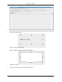
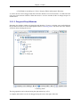
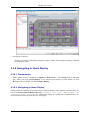
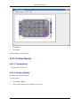
In the top of the Synoptic Hierarchy (shown un-docked) the two display with their respective label are shown. In the bottom the project-folder is shown, containing the two saved displays.
12. Right-click on Display1.uss in the bottom part of the Synoptic Hierarchy and select from pop-up
menu: Add Navigation to Display.
A navigation button is added to currently selected display (Display2.uss). The navigation button
will navigate (upon activation) to Display1.uss, when Display2.uss is executed.
13. Save both displays again and close the Editor.
USS User Manual
86
2006-11-08 17:01
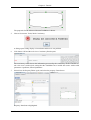
Chapter 2: Tutorial
14. Open the Executor from installed icon.
15. In Executor open display file: Display2.uss from the Project-folder.
16. Click on the navigation-button with text: Display1
Executor opens Display1.uss in a new tab.
2.12. Add Symbols
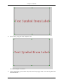
The USS Editor can be used to create symbols that can be reused in the displays. Symbols are contained in Symbol Libraries.
USS User Manual
87
2006-11-08 17:01
Chapter 2: Tutorial
2.12.1. Lesson in creating Symbols
1.
Start by openning the editor via installed icon, close all tool-views.
2.
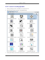
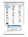
Open the Symbol Library from menu: View|Symbol Library
3.
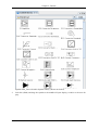
In the Symbol Library select from the drop-down box (ComboBox) the symbol library: Electrical
USS User Manual
88
2006-11-08 17:01
Chapter 2: Tutorial
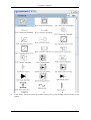
4.
In the library: Electrical select the symbol: E265_Fuse, by left-clicking with the mouse on the
symbol.
USS User Manual
89
2006-11-08 17:01
Chapter 2: Tutorial
Symbol E265_Fuse selected in Symbol Library (shown un-docked).
5.
Left-click (Hold) and drag the symbol to the middle off open display, to add it to the new display.
USS User Manual
90
2006-11-08 17:01
Chapter 2: Tutorial
The Symbol is added to the display, as an element using the image material given by the symbol.
This element contains a reference to the symbol, so that if the symbol library is updated, the symbol-element in the display, will be likewise.
6.
Resize the symbol-element by dragging its control-points in the corners (make it larger).
The symbol-element is resized.
7.
Open the tool-view: Property Editor to show the properties for the element.
USS User Manual
91
2006-11-08 17:01
Chapter 2: Tutorial
Symbol-element properties are shown.
8.
Undock the Property Editor and click the property: Reset Image Size - button to reset back to the
original size of the symbol.
USS User Manual
92
2006-11-08 17:01
Chapter 2: Tutorial
Property is reset.
9.
Re-dock the Property Editor.
The display shows the reset symbol-element in the display.
10. In the property editor click the property: Symbol Name.
USS User Manual
93
2006-11-08 17:01
Chapter 2: Tutorial
11. In the property editor change the property: Symbol Name, to E30_Heater.
USS User Manual
94
2006-11-08 17:01
Chapter 2: Tutorial
12. Observe the the display symbol-elements icon is changed to the heater icon.
13. Rotate the symbol-element by selecting from menu: Element|Element|Riotate|Left
USS User Manual
95
2006-11-08 17:01
Chapter 2: Tutorial
The symbol-element is rotate counter-clockwise (left). This feature is available not only for symbol-elements. Some complex elements, cannot be rotated.
14. In the property editor click to the property: Auto Scale Image.
USS User Manual
96
2006-11-08 17:01
Chapter 2: Tutorial
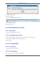
15. Uncheck the property: Auto Scale Image.
16. Observe that the icon of the symbol-element is resize to its real size (in pixels) and but the extend
of the symbol-element is persistent.
USS User Manual
97
2006-11-08 17:01
Chapter 2: Tutorial
2.13. Create New Symbols
The USS Editor can be used to create new symbols and symbol-libraries.
2.13.1. Lesson in creating Symbols
1.
Start by openning the editor via installed icon, close all tool-views.
2.
Open the Symbol Library from menu: View|Symbol Library
3.
Make a new label by selecting from menu: Element|Add|Label
Label is created in the display.
4.
Open the property editor from menu: View|Property Editor
USS User Manual
98
2006-11-08 17:01
Chapter 2: Tutorial
Properties are shown from label.
5.
Set the properties to match approximately, following picture:
USS User Manual
99
2006-11-08 17:01
Chapter 2: Tutorial
Change: Font, Font Color, Label Text Autosize, Label Text Horizontal Alignment, Label Text
Vertical Alignment and Label Text. Giving the following label result:
6.
Resize the label by dragging its control-points in the corners (make it larger).
USS User Manual
100
2006-11-08 17:01
Chapter 2: Tutorial
The label is enlarged; text is followed because we set the property 'Label Text Autosize' to
checked.
7.
Open the Symbol Library from menu: View|Symbol Library.
USS User Manual
101
2006-11-08 17:01
Chapter 2: Tutorial
Symbol Library shown.
8.
Click the button: Edit, and in the pop-up menu select: Create New Library
Dialog for setting new library name is shown.
9.
Set name to: Test Library.
USS User Manual
102
2006-11-08 17:01
Chapter 2: Tutorial
10. Click Ok, and select new Library in the drop-down-box (ComboBox)
A new empty symbol library is created.
11. Add a new symbol, created from the previously created label, by clicking the button: Edit in the
symbol library and selecting: Create Symbol from Selected Elements
Dialog shows the configuration possibilities for the new symbol.
12. Select Type: Image (SVG) and name the symbol: Test Symbol.
USS User Manual
103
2006-11-08 17:01
Chapter 2: Tutorial
13. Click button: OK to create symbol.
The symbol is created in the new library. Symbols can only be created in the user symbol libraries, because predefined symbol libraries are destributed as part of the USS package an will be
overwritten on system update. They are USS-version persistent so to speak.
14. Now add a rectangle to the display from menu: Element|Add|Rectangle.
A rectangle is added to the open display.
15. Move the rectangle, so that it acts as a border to the previously created label.
USS User Manual
104
2006-11-08 17:01
Chapter 2: Tutorial
16. Select both by using the menu: Edit|Select All.
Label and rectangle are selected.
17. In the symbol library press button: Edit, and select from pop-up menu: Create new Symbol from
selected Elements.
USS User Manual
105
2006-11-08 17:01
Chapter 2: Tutorial
Configuration dialog is shown.
18. Set the properties, Name: Test Sub-Display Symbol Type: SubDisplay (USS)
19. Click button: OK to create symbol.
Symbol is created as a Sub Display. Sub Display are real USS-displays that can be embedded in
the symbol, this powerful feature, allows for high versatility in creating symbol.
20. Delete created elements in the display, by selecting from menu: Edit|Delete
USS User Manual
106
2006-11-08 17:01
Chapter 2: Tutorial
Label and rectangle are deleted.
21. Select the created symbol: Test Sub-Display Symbol in the symbol Library.
Symbol selected.
22. Left-click (hold) on selected symbol and drag it to the middle of the open display to add it.
USS User Manual
107
2006-11-08 17:01
Chapter 2: Tutorial
The symbol containing a sub-display is added; inside the sub-display are the label and rectangle
elements.
2.14. Use advanced elements
The USS package feature several advanced display elements, which give powerful visualisation posibilities.
2.14.1. Lesson in creating advanced elements
1.
Start by openning the editor via installed icon, close all tool-views.
2.
Open the Property Editor from menu: View|Property Editor
USS User Manual
108
2006-11-08 17:01
Chapter 2: Tutorial
3.
Make a new Elliptic Meter by selecting from menu: Element|Add|Elliptic Tick Meter
The elliptic formed meter is created in display.
4.
Undock property editor and move it, so the display can be fully seen (without overlapping from
property editor).
5.
Enlarge meter by dragging its corner-control-points and move it to the middle of the display by
left-clicking (hold) on the Elliptic Tick Meter and dragging it.
Elliptic Tick Meter is resized and located approximately in the middle of display.
6.
In the property Editor set the property: Border Used, to checked and set border color to R: 0, G: 0
and B: 139 (a blue colour).
USS User Manual
109
2006-11-08 17:01
Chapter 2: Tutorial
7.
Redock the property editor.
8.
In property editor set property: Label Text, to Ellip. Tick Meter
USS User Manual
110
2006-11-08 17:01
Chapter 2: Tutorial
Label is shown in meter.
9.
In property editor set property: Meter Tick Indicator, to Slider (Kite)
Indicator is changed.
10. In property editor set property: Field Style, to Center
USS User Manual
111
2006-11-08 17:01
Chapter 2: Tutorial
Field is now shown and centered.
11. In property editor set the following properties: Start angle: 90 Sweep angle: 180 Tick Color: R:
165, G: 42, B: 42 Tick Indicator Color: R: 102, G: 205, B: 170
The Elliptic Tick Meter changes appearance and meter-range is changed.
12. Select data source field in the property editor.
13. Click the property button: '...', to open the data source configuration dialog.
USS User Manual
112
2006-11-08 17:01
Chapter 2: Tutorial
The data source dialog is used by the editor to edit all data sources related to display elements.
14. In the data source dialog, chnage the Data Source Type to Computation
Details are changed to computation details.
15. Select from drop-down-box (ComboBox) with text: Select Symbol, the expression-symbol: PI.
16. Click in Expression field and type on keyboard: + (plus-key)
17. Open the System Configuration Browser by clicking the button: ... Select the path-location:
\Comms\CTC1\Unit_Temp_DMC (OPS View: Onboard Telemetry)
USS User Manual
113
2006-11-08 17:01
Chapter 2: Tutorial
18. Click button: Add, followed by button: Close.
Label and rectangle are selected.
19. In the data source dialog set the Unit to: deg C
USS User Manual
114
2006-11-08 17:01
Chapter 2: Tutorial
Unit is changed, the unit is a textual property of the data source.
20. Click button: OK to change data source.
21. Open previewer from menu: Tools|Previwer
USS User Manual
115
2006-11-08 17:01
Chapter 2: Tutorial
The created Elliptic Tick Meter is previewed.
22. Use the slider at the bootom of the open dialog, to simulate values given to the data source and
the effect on the meter..
USS User Manual
116
2006-11-08 17:01
Chapter 2: Tutorial
The indicator moves as the slider is moved.
2.15. Change USS Properties File
The USS package feature a common configuration system, which is located in the home folder in the
folder: .uss-<USS_VERSION> (EX: .uss-2.6.0)
2.15.1. Lesson in USS properties
The USS Editor and Executor use Data Quality Indicator definition to give information about the state
of the data being processed.
the lesson assumes the XML editor KXML-editor is installed, as well as the Kate (KDE editor).
1.
Opening a file browser to the >HOME_DIRECTORY</.uss-<USS_VERSION> (EX: .uss-2.6.0)
directory. Here open the file: uss.config (you might need to change file-filtering to All-Files)
USS User Manual
117
2006-11-08 17:01
Chapter 2: Tutorial
Folder contains many files, ie. log-file, the folder also contains the uss.config file, which contains
the settings for USS.
2.
Opening the Kate-editor and browser to the >HOME_DIRECTORY</.uss-<USS_VERSION>
directory. Here open the file: uss.config.
The Kate-Editor shows the content of the xml-formatted uss.config file for the USS system. The
Kate editor contains features for context highlighting. Browse down to see the uss properties,
they can be changed manually by editing via Kate.
USS User Manual
118
2006-11-08 17:01
Chapter 2: Tutorial
3.
Close the Kate editor again.
4.
Opening the KXML-editor and browser to the >HOME_DIRECTORY</.uss-<USS_VERSION>
directory. Here open the file: uss.config.
The KXML-Editor shows the content of the xml-formatted uss.config file for the USS system.
The XML tree hierarchy is shown on the left and the content of the selected node on the right,
where the content can be edited.
5.
Browse
in
the
XML
tree
hierarchy
to
the
node:
properties/
root/node/node/node/node/node/node/map/entry(1) and select it to show the content.
Changing the values here will change view settings X value of the editor, which can be edited
through the Editor Preferences also.
6.
Try changing the value to 25.0, to set the Editors default view setting for the X value.
The value is change, and will be used in future invocations of the editor. If editor is open it has to
be restarted to laod the new value.
2.16. Select SCOE Files
The USS package uses a SCOE file, to ease creation of end-items.
2.16.1. Lesson in changing the SCOE file
1.
Start by openning the editor via installed icon, close all tool-views.
USS User Manual
119
2006-11-08 17:01
Chapter 2: Tutorial
2.
Close the open default new display, to allow changing of the SCOE file.
No display open.
3.
Open the editor preferences by selecting: Edit|Preferences
USS User Manual
120
2006-11-08 17:01
Chapter 2: Tutorial
USS Editor preferences dialog is opened.
4.
Left-click with the mouse on the right to the category: MDB-SCOE.
The preferences for the SCOE File is shown, some properties are only informational (can not be
changed and are read from file choosed).
5.
Click button: Browse, to open a dialog for changing the SCOE File.
USS User Manual
121
2006-11-08 17:01
Chapter 2: Tutorial
The dialog opens in the default SCOE file directory.
6.
Select a new SCOE file.
New SCOE file selected.
7.
Click button: Choose File.
USS User Manual
122
2006-11-08 17:01
Chapter 2: Tutorial
The new SCOE file is now choose.
8.
Click button: OK, to change the editor preferences (uss.properties file). The editor will reload the
System Configuration Browser (based on the SCOE file)
Reloading of new SCOE file takes some seconds.
9.
A confirmation box occures to rerun consistency checker on open displays, all displays
(project-folder) or not to run-checker.
Choose not to run.
10. SCOE file is reloaded in the System Configuration Browser.
USS User Manual
123
2006-11-08 17:01
Chapter 2: Tutorial
2.17. Check Consistency
The USS Editor can check the consistency of created displays against the configured SCOE file and
there by save time for display developers.
2.17.1. Lesson in checking display consistency
1.
Start by openning the editor via installed icon, close all tool-views.
USS User Manual
124
2006-11-08 17:01
Chapter 2: Tutorial
2.
Add a label (menu: Element|Add|Label) Double-click (left-mouse-button) to edit text inline and
write text: Label for check
Label created and text changed.
3.
Add a TankMeter (menu: Element|Add|TankMeter)
TankMeter created.
4.
Open Property Editor (Menu: View|Property Editor)
USS User Manual
125
2006-11-08 17:01
Chapter 2: Tutorial
The properties for the advanced element TankMeter is shown.
5.
Choose from menu: Tools|Check Consistency.
A dialog opens stating display is inconsistent and there is one problem.
6.
Click button: OK and the tool-view: Consistency Result opens.
The consistency results shown the information processed by the consistency checker and the results. One error is marked red, stating that the TankMeter has a invalid data source with invalid
parameters: OpsName, SID and pathname.
7.
Select/focus the Property Editor again, and select the property: Data Source.
Property: Data Source highligthed.
USS User Manual
126
2006-11-08 17:01
Chapter 2: Tutorial
8.
Click button: ..., to change open the data source dialog.
Data source dialog opens showing the data source attached to the TankMeter.
9.
Click under Details for External Data Source on button: '...', to open the System Configuration
Browser.
USS User Manual
127
2006-11-08 17:01
Chapter 2: Tutorial
System Configuration Browser opens (in OPS View: Onboard Telemetry).
10. In the search field (left of button: Search) type: 'Sensor', and click button: Search.
USS User Manual
128
2006-11-08 17:01
Chapter 2: Tutorial
System Configuration Browser searches and selects the end-item: \BLB\LSS\S13\O2\Sensor.
11. Click button: Change.
System Configuration Browser changes the data source in the Data Source Dialog.
12. Click button: Close.
USS User Manual
129
2006-11-08 17:01
Chapter 2: Tutorial
Data Source Dialog now has a fully configured data source.
13. Click button: OK, in data source dialog.
Shown Data Source in property editor is now changed.
14. Now check consistency again (Tools| Check Consistency).
Dialog shows that display is now consistent.
15. Click button: 'OK', to close confirmation dialog.
USS User Manual
130
2006-11-08 17:01
Chapter 2: Tutorial
16. Select/focus the Consistency Results View again.
17. To generate a HTML report, select from menu: File|Generate HTML report
2.18. MDB Displays
The USS Editor can work with a MDB. Displays can be synchronized (normally and forced/overUSS User Manual
131
2006-11-08 17:01
Chapter 2: Tutorial
write), submitted (new displays / check-in of changes) and Deleted.
Lesson setup: A working connection to a MDB is needed, proper setup of editor preferences to the
MDB in question.
2.18.1. Lesson in using the editor MDB interfacing
1.
Start by openning the editor via installed icon, close all tool-views.
2.
Open Property Editor from menu: View|Property Editor
USS User Manual
132
2006-11-08 17:01
Chapter 2: Tutorial
3.
Make a label (Menu: Element|Add|Label) and set property: Label Text, in property editor to:
Test MDB Connection.
Teh MDB Browser is loading configuration data from the MDB (can take minutes).
USS User Manual
133
2006-11-08 17:01
Chapter 2: Tutorial
4.
Select from menu: File|MDB|MDB Browser
The MDB Browser is loading configuration data from the MDB (can take minutes).
5.
After loading of MDB configuration data, the MDB browser dialog opens.
6.
Open
and
select
the
MDB
path:
'\APM\COMMON_TEST_SUPP\GRD_DATA\USS\EDITOR\MANUAL_TESTS', and press
button: Sync.
USS User Manual
134
2006-11-08 17:01
Chapter 2: Tutorial
The
MDB
Browser
is
synchronizing
the
MDB
node:
'\APM\COMMON_TEST_SUPP\GRD_DATA\USS\EDITOR\MANUAL_TESTS', as well as all
the sub-nodes and displays.
7.
Close MDB Browser (press button: 'Close').
USS User Manual
135
2006-11-08 17:01
Chapter 2: Tutorial
Dialog closes.
8.
Save display by selecting from menu: 'File|Save'.
The save dialog appears, opened in the uss-project folder.
9.
Choose
save-path:
'<uss-project-directory>/<CU_DIRECTORY>/APM/COMMON_TEST_SUPP/GRD_DATA/US
S/EDITOR/MANUAL_TESTS/' And file-name: 'MDBTEST.uss'
USS User Manual
136
2006-11-08 17:01
Chapter 2: Tutorial
10. Click button: Save, to save file.
Display is saved in correct path MDB synchronization.
11. To add display to MDB, choose from menu: File|MDB|Export adding to MDB.
Confirmation is shown, when display is submitted.
12. To verify the MDB export of the new display, choose from menu: File|MDB|MDB Browser And
browse
to
the
to
the
MDB-path:
\APM\COMMON_TEST_SUPP\GRD_DATA\USS\EDITOR\MANUAL_TESTS
USS User Manual
137
2006-11-08 17:01
Chapter 2: Tutorial
MDB Browser shows exported display.
13. Select the MDB display: MDBTEST, and press button: sync.
USS User Manual
138
2006-11-08 17:01
Chapter 2: Tutorial
Synchronization under way.
Synchronization done.
14. Now open the display again for editing by clicking the button: 'Lock For Edit', in the MDB
Browser.
USS User Manual
139
2006-11-08 17:01
Chapter 2: Tutorial
MDB Browser is locking the display.
MDB Browser is done locking the display.
15. Click button: Close, in MDB Browser.
16. Close the open display, selecting from menu: File|Close. Open Synoptic Hierarchy by selecting
from menu: View|Synoptic Hierarchy.
USS User Manual
140
2006-11-08 17:01
Chapter 2: Tutorial
Synoptic Hierarchy shows the project-files.
17. Browse to the saved display in the project-folder via the Synoptic Hierarchy, path:
'<uss-project-directory>/<CU_DIRECTORY>/APM/COMMON_TEST_SUPP/GRD_DATA/US
S/EDITOR/MANUAL_TESTS/MDBTEST'.
18. Right-click on project-display: MDBTEST.uss, and choose from pop-up menu Open display.
USS User Manual
141
2006-11-08 17:01
Chapter 2: Tutorial
Display is reopened.
19. Add a polygon from menu: Element|Add|Polygon.
20. Add a navigation button from menu: Element|Add|Navigation Button.
USS User Manual
142
2006-11-08 17:01
Chapter 2: Tutorial
The display has additional elements: polygon and navigation button.
21. Select the polygon by left-clicking on it.
22. Move the polygon by left-click (hold) and dragging it.
23. Left-click (hold) and move one of the control-points of the polygon, to change its shape.
USS User Manual
143
2006-11-08 17:01
Chapter 2: Tutorial
Polygon is changed.
24. Open the Property Editor by selection menu: View|Property Editor.
25. Select the button by left-clicking on it.
Button properties are shown in the Property Editor.
26. Click on the button: Button1, for the property: Released Label Text to open text edit dialog.
27.
USS User Manual
144
2006-11-08 17:01
Chapter 2: Tutorial
Dialog for multi-line text edit shows new text.
28. Click button: OK.
29. Save display by choosing from menu: File|Save.
30. Submit the changes to the MDB by selecting from menu: File|MDB|Export to MDB.
Confirmation is shown of submition.
31. Delete the display file in the MDB, by selecting from menu: File|MDB|Delete.
After deletion of the display in the MDB, the editor will ask for confirmation to delete the display on the local file-system.
32. Click button: Yes, to delete the tutorial display-file.
2.19. Quick Tutorial
This tutorial section explains the preparations needed in order to run both USS executor and USS editor. After this it gives a short tutorial on USS editor, which shows how to create a new ground ops
(Satmon like) display, the converting of GWDU ground displays in batch operation and how to check
GWDU displays for consistency. It finishes with a tutorial on USS executor, which explains how to
connect and disconnect a display, shows direct commanding of FWDU displays, shows a GWDU display aswell as imported Satmon displays samples and PCS display samples and shows the commanding via MCS Tools.
2.19.1. Preparation
USS User Manual
145
2006-11-08 17:01
Chapter 2: Tutorial
This section explains the preparations needed in order to run both USS executor and USS editor.
1.
Start MCS Console
a.
Start Task Selector by typing ts& into the command shell.
b.
Start TSCV and press continue on all warnings that may appear.
c.
Start MCC_Client.
• Shutdown MCC_Client if already running.
• Start MCC_Client and wait until it reaches active status.
d.
Start HCI Online Test Control.
• In the HLCL shell type init_client to start TM acquistion.
2.
Keep "DOWNLINK_STATUS" GWDU display open (for later USS side-by-side test).
3.
Switch to an empty desktop workspace.
4.
Open a task selector by opening a shell and typing ts& into it.
2.19.2. Editor Tutorial
This section gives a short editor tutorial. It shows how to create a new ground ops (Satmon like) display, the converting of GWDU ground displays in a batch operation and how to check GWDU displays for consistency.
2.19.2.1. Creating new ground ops (Satmon like) display
2.19.2.1.1. Setting project root folder and MDB configuration
• Close all open displays, this is a requirement to change the project root folder
• Choose Edit > Preferences
• In the popup dialog choose Project tab in the tree structure on the left.
• Click Browse button to set the Root folder to /home/<user>/uss-project .
2.19.2.1.2. Importing and exporting displays from and to MDB
• Start my making a new display from menu choose: File|New
• Add a label by choosing from menu: Element|Add|Label, and add a text by editing label text in
Property Editor (open it if not open by choosing from menu: Views|Property EDitor)
• Save display by choosing from menu: File|Save. In dialog save display to location and displayname
(capitalize
name
of
display):
USS User Manual
146
2006-11-08 17:01
Chapter 2: Tutorial
[USS-Project-folder]/[CU-DIRECTORY]/APM/COMMON_TEST_SUPP/GRD_DATA/USS/EDI
TOR/MANUAL_TESTS/TUTORIAL.uss
• Press ok to save dialog, and choose from menu: File|MDB|Export adding to MDB
• Wait for operation to finish and press ok to confirmation dialog. Displays are now exported to the
MDB.
• Close all displays by choosing from menu: File|Close all, displays might need to be save or cancelled.
• Choose File > MDB > MDB Browser (sync/lock-for-edit).
• Select
\APM\COMMON_TEST_SUPP\GRD_DATA\USS\EDITOR\MANUAL_TESTS\TUTORIAL in
the browser.
• Right-click then select Sync from the Version Control popup-menu and wait for synchronization to
complete.
• In the popup dialog click OK.
• Click Apply.
• In the synoptic hierarchy on the right side select root folder (the one which you have configured
in Setting project root folder and MDB configuration.
• Navigate to \APM\COMMON_TEST_SUPP\GRD_DATA\USS\EDITOR\MANUAL_TESTS.
• Right-click on TUTORIAL.uss and select Open Display. TUTORIAL opens in editor view.
• Right-click on display. Select Lock-for-Edit on MDB.
• In the popup dialog click OK.
• Edit display.
• Choose File > Save display.
• Right-click on display. Select Export to MDB.
• In the popup dialog click OK.
• In the popup dialog click OK.
2.19.2.1.3. Editing displays
• Creating Elements i.e. labels, fields etc.
1.
Choose Elements > Add .
2.
Select Label or Data Field.
• Changing properties of elements.
1.
Right-click on newly created element (label, data field etc.)
USS User Manual
147
2006-11-08 17:01
Chapter 2: Tutorial
2.
From the popup dialog select action you would like to perform (e.g. align, move, order, rotate
or scaling).
• Drag and drop an item from the system configuration browser onto the display.
• Drag and drop multiple items from the system configuration browser onto the display.
2.19.2.1.4. Previewing a display
• Save current display by choosing File > Save.
• Choose Tools > Preview Display....
• Watch display open in a previewer, the slider (in the bottom of window) can be used to see any dynamic contents.
• Close previewer window.
2.19.2.2. Converting GWDU ground displays as batch operation
• Choose Tools > Run Batch Operation... .
• Click Browse and set source directory to <USS base directory>/examples/import/gwdu.
• Click Browse and set destination directory to /home/<user>/uss-project .
• Click Convert: The batch process starts.
• Click Close.
• After conversion: Close and reopen synoptic hierarchy.
• Open a converted USS display in /home/<user>/uss-project/mcs/... for
(/APM/COL_CC/MCS_OPS/CONFIG/SYNOPTICS/MCS/DOWNLINK_STAT.uss).
example
2.19.2.3. Checking GWDU display for consistency
• Open /APM/COL_CC/MCS_OPS/CONFIG/SYNOPTICS/MCS/DOWNLINK_STAT.uss.
• Choose Tools > Consistency Check....
• In the Consistency checker report displayed at the bottom, double click line with error item, item
gets selected in display.
2.19.3. Executor Tutorial
This section gives a short tutorial on how to use the executor. It shows how to connect to and disconnect displays from MCS. It explains direct commanding from a FWDU display aswell as commanding
via MCS Tools. It explains how to show a GWDU display, imported Satmon display and PCS display
samples.
USS User Manual
148
2006-11-08 17:01
Chapter 2: Tutorial
2.19.3.1. Connecting and opening displays
• Choose Options > MCS Connection... to connect to MCS.
• In the popup dialog enter the correct connection data for service (e.g. CIS) and host (e.g. localhost)
and port (e.g. 7060).
• Then click Connect.
• Open Col Home display.
2.19.3.2. Show direct commanding (from FWDU display)
• Open /APM/FLTSYS/OPS/SYNOPTICS/ECLSS/CFA1 display.
• Choose Options > Preferences.... Enable direct commanding.
• In the popup window select Commanding in the tree structure on the right side.
• Check Enable Commanding.
• Check Direct Commanding.
• Click OK.
• Right-click in white box under Fan Speed.
• In the popup dialog select Line Graph.
• Leave line graph window open.
• In the display click on Pwr Off command button.
• Click Execute button in the bottom of the display: Watch command feedback in response panel.
Pwr changes to Off, Fan Speed drops to 0 rpm. Watch line graph changing value.
2.19.3.3. Show GWDU display
• Open APM/COL_CC/MCS_OPS/CONFIG/SYNOPTICS/MCS/DOWNLINK_STAT.gwdu
show updated telemetry
to
• Click TM Packet Status... button
• Show monitoring
• Show display navigation
• Show parameter properties
1.
Right-click on parameter.
USS User Manual
149
2006-11-08 17:01
Chapter 2: Tutorial
2.
In the popup dialog select Properties.
3.
Click Close.
• Show display search for selected paramter
• Right-click on parameter.
• In the popup dialog select Find Parameter In Other displays.
• Click Close.
2.19.3.4. Show commanding via MCS Tools
• Choose Options > Preferences.
• Select Commanding in the tree structure on the right.
• Check Enable Commanding.
• Uncheck Direct Commanding.
• In Command Target select or enter Manual Stack@mcs-cc-3.
• Click OK.
• Start MCS Tools: Task Selector > Onboard Commanding.
• In MCS Tools select Options > Preferences. Set remote commanding to Manual
Stack@mcs-cc-3.
• Select CFA1 Deactivation and Execute.
• Select row in manual stack, Enable, Activate.
• Select CFA1 Activation and Execute.
• Select row in manual stack, Enable, Activate.
2.19.3.5. Show imported Satmon display samples
• Choose File > Open....
• Open $USS_HOME/examples/import/uss/satmon/4005.uss.
• Compare with screenshot of original display:
USS User Manual
150
2006-11-08 17:01
Chapter 2: Tutorial
• Open $USS_HOME/examples/uss/satmon/5001.uss
• Compare with screenshot of original display:
USS User Manual
151
2006-11-08 17:01
Chapter 2: Tutorial
2.19.3.6. Show PCS display samples
• Choose File > Open Display.
• Open $USS_HOME/share/displays/pcs/xml/Columbus_ECLSS.xml
• Open $USS_HOME/share/displays/pcs/xml/Col_Air_Sensors.xml
• Open line graph on Liquid Carryover Sensor 1.
USS User Manual
152
2006-11-08 17:01
Chapter 3: Editor
3.1. Introduction
The USS Editor is the application for creating USS displays for later execution in the USS Executor.
The Editor supports the definition of layout, composition and dynamic properties of synoptic displays.
The operations of the Editor will be familiar to users of MS Visio with the addition of connecting
graphical elements with MDB end-items.
The Editor can connect to the Columbus MDB to retrieve and store display definitions or it can work
with displays directly on the file system.
The Editor comes with static and dynamic symbols as defined in Appendix C of the Display and
Graphics Commonality Standard. The symbols are found in the Symbol Library and can be dragged
and dropped onto the synoptic display.
The Editor can import existing display definitions from
• SAMMI II
• DataView/Gipsy
• PREP
Imported display definitions become USS displays meaning that they will have the USS XML-based
file format and the .uss file extension. The imported displays cannot be exported back into the legacy
display formats.
3.2. The Editor Workspace
When opening the Editor, the workspace will appear. The workspace contains menus, toolbars, the
display area in a tab window to the right and a number of views to the left.
The Editor menus addapt to selections and disables options that are not possible, examples are MDB
and element operations
USS User Manual
153
2006-11-08 17:01
Chapter 3: Editor
The windows can be arranged within the Editor by dragging them to the desired position. The views
in the Editor are:
• The display area: The area for creating the display by adding and arranging elements
• System configuration browser: The System configuration browser is a tool-view for the Editor to
ease creation of data sources, commands and navigation. It is based on the SCOE XML file in a
tree structure. The System configuration browser can show the SCOE information in OPS or Path
view (OPS or path -name is used for sorting SCOE xml-nodes). It provides Drag and Drop functionality for TM and TC information and filtering and hierarchical browsing of the selected MDB
configuration
• Synoptic hierarchy: The Synoptic Hierarchy is a tool-view for the Editor to ease navigation of currently open displays and the USS project displays (defined by the project root-folder). It provides
possibility to create navigation target to project displays, and easy opening hereof.
• Symbol library: The library of symbols that can created, edited and dragged onto the display
• Property editor: View and edit the properties of the selected element(s)
• Display View Settings: Preferences for current display
• Consistency results: Report of the last run consistency check
The toolbars can be dragged and docked to any position.
3.2.1. Arranging Views and Tab Windows
USS User Manual
154
2006-11-08 17:01
Chapter 3: Editor
The layout of the Editor can be customized. Windows can be minimized, maximized, closed and
moved around to dock in order to create a personalized window layout.
3.2.1.1. Docking mechanishm of editor panels
The USS Editor features a docking framework for tool- and display views. By default views are
opened as frames inside the main editor application. Small docking control icons allows you to:
1.
Undock/Minimize/Close - when view is docked, ie. inside main window
2.
Dock/Close - when view is undocked, ie. appears in a seperate window
3.
Undock/Minimize/Maximize/Close - when views are collected in tabs (multiple views in tabs)
3.2.1.2. Basic Concepts
The Views listed above are layed out in tab windows .
USS User Manual
155
2006-11-08 17:01
Chapter 3: Editor
A Tab Window containing two Views: Property Editor and Synoptic Hierarchy
A window divider can be dragged with the left mouse button to resize the windows. A window divider
is the grey area between windows. When the mouse is over the window divider it changes shape to a
double arrow.
3.2.1.3. Drag and Drop Windows
Rearrange the docking windows by dragging and dropping. To move a window press and hold down
the left mouse button on its tab and drag the window. A docking frame will show where the window
will dock when releasing the mouse.
A docking frame
The drag operation can be aborted using the right mouse key or Esc.
A complete tab window can also be dragged using the area to the right of the tabs.
USS User Manual
156
2006-11-08 17:01
Chapter 3: Editor
A view can be dragged into another tab window.
The tabs of the views within a tab window can be rearranged by dragging the tabs to their new position.
3.2.1.4. Minimize and Maximize
Views and tab windows can be minimized to the window bar at the bottom edge of the Editor by
clicking the minimize button. The previous location of a minimized or maximized window is remembered so that it can be restored to that location. The minimized window can also be shown by
clicking on it. The window can be hidden by clicking on the tab again. The windows can be restored
by clicking the restore buttons. A tab window can be maximized by clicking the maximize button or
by double clicking the tab.
The window bar
3.2.1.5. Tab Layout
Tabs are scrolled when there is no room for all the tabs to be visible at the same time. A tab can then
be quickly selected via a drop down list. The selected tab is scrolled so it becomes visible.
Scrolling tabs
3.2.2. Editor Menus
The Editor menus addapt to selections and disables options that are not possible, examples are MDB
and element operations
The following top menu items exist in the editor:
• File: File / Display manipulations (open, save, reload, MDB operations, print etc.) Click for File
menu description
• Edit: Editing / selecting of displays and elements, and preferences. Click for Edit menu description
• View: Opening / Closing of editor tool views. Click for View menu description
• Tools: Editor Internal / External Tools. Click for Tools menu description
• Element: Display element manipulations. Click for Element menu description
USS User Manual
157
2006-11-08 17:01
Chapter 3: Editor
• Window: Window zooming and navigation. Click for Window menu description
• Help: Help menu. Click for Help menu description
3.2.2.1. Editor Edit Menu Item
The following operations are available from the Edit menu (some operations are inactive if they are
not feasable):
• Undo: Undos the latest edit in current display
• Redo: Redos the latest undo in current display
• Copy: Copies current element selection to clipboard
• Cut: Cuts current element selection to clipboard
• Paste: Pastes content of clipboard to current display
• Duplicate: Duplicates current element selection in current display
• Set Element as Default: Sets current selected element as default for new elements
• Delete: Delete current element selection
• Button Edit: Sub menu for button release / press look editing
• Select Invert: Inverts the current element selection (non-selected becomes selected and vice a
versa)
• Select All: Selects all elements in current display
• Select All of Same Type: Selects all elements of same type in current display
• Select All of Same Depth: Selects all elements of same depth (depth property) in current display
• Focus to Property Editor: Opens / focuses to the Property Editor showing properties for currently
selected elements
• Preferences: Open the preferences configuration dialog
3.2.2.2. Editor View Menu Item
The following operations are available from the View menu (by toggle a view is meant: If view is
open it is closed, and vice a versa):
• System Configuration Browser: Toggles the System Configuration Browser tool view
• Synoptic Hierarchy: Toggles the Synoptic Hierarchy tool view
• Symbol Library: Toggles the Symbol Library tool view
• Property Editor: Toggles the Property Editor tool view
• View Settings: Toggles the View Settings tool view
USS User Manual
158
2006-11-08 17:01
Chapter 3: Editor
• Consistency Results: Toggles the Consistency Results tool view
• Toolbar: Sub-menu Toolbar for adding/removing toolbars
• Refresh: Refresh of open views
3.2.2.3. Editor Tools Menu Item
The following operations are available from the Tools menu (some operations are inactive if they are
not feasable):
• Preview Display...: Opens the Previewer for currently selected display
• Open Display in Executor...: Opens the Executor for currently selected display (save needed)
• Consistency Check: Executes a consistency check for currently selected display (opens Consistency Results on errors)
• Run Batch Operation...: Open the dialog for executing batch operations
• Find Parameter...: Open dialog for selecting an end-item to search for in project-displays (in
project-root-folder)
3.2.2.4. Editor Element Menu Item
The following operations are available from the Element menu (some operations are inactive if they
are not feasable):
• Add: Sub-menu containing all display elements that can be added to current selected display
• Align: Sub-menu containing all alignment operations that can applied to current selected elements
• Grouping: Sub-menu containing all grouping operations that can applied to current selected elements
• Move: Sub-menu containing all movment operations that can applied to current selected elements
• Depth: Sub-menu containing all depth arrangment operations that can applied to current selected
elements
• Rotate: Sub-menu containing all rotation operations that can applied to current selected elements
• Scaling: Sub-menu containing all scaling operations that can applied to current selected elements
• Transform: Performs a transform to current selected elements
3.2.2.5. Editor Window Menu Item
The following operations are available from the Window menu (some operations are inactive if they
are not feasable):
• Zoom: Sub-menu containing all zooming operations that can applied to current selected display
• Back: Goes back to previously selected display
USS User Manual
159
2006-11-08 17:01
Chapter 3: Editor
• Forward: Goes forward to previously selected display (opposite direction of Back)
3.2.2.6. Editor Help Menu Item
The following operations are available from the Help menu (some operations are inactive if they are
not feasable):
• Help Contents: Opens the Help contents in the web-browser
• Search...: Opens the a search dialog for searching the help contents
• About...: Shows the product information for the USS Editor
3.3. Working with Displays
The following operations are available from the File menu (some operations are inactive if they are
not feasable):
• New: Create new, empty USS display
• Open...: Open existing USS, FWDU, GWDU or PREP display from the file system
• Reload: Revert to the saved version of the current display file. This function can be used to discard
changes made in the display since the last save or to acquire changes made in the display file outside the editor
• Close: Close the current display
• Close all: Close all open displays
• Save: Save the current display to the file system
• Save as...: Save the new display to the file system
• Save all: Save all open displays to the file system
• MDB | Browser (sync/lock-for-edit/delete): Show the MDB browser
• MDB | Import from MDB: Import display from the MDB
• MDB | Forced Import from MDB (revert): Import display from the MDB and overwrite local
display file, no matter synchronization state
• MDB | Lock-for-Edit on MDB: Lock-for-Edit the display from the MDB
• MDB | Export adding to MDB: Export a new display to the MDB
• MDB | Export to MDB: Export display to the MDB
• MDB | Delete in MDB: Delete display in the MDB
• Create HTML Report...: Create a detailed report about the current display
• Export to Image...: Export the current display to an image with or without annotation, supported
formats [GIF, PNG, SVG]
USS User Manual
160
2006-11-08 17:01
Chapter 3: Editor
• Print...: Print the current display
• Print Preview...: Preview the print of current display
• Preferences...: Change Editor preferences for new displays
• Recent files: List of the 4 most recent files for easy access
• Exit: Exit the Editor
3.3.1. Merging Displays
For users of GWDU the function of merging displays will be familiar. In the USS Editor merging is
done by selecting, copying and pasting elements between the displays to be merged. Copy-pasting can
be done as described in Basic Operations.
3.3.2. Previewing Displays
The Editor allows for previewing USS displays. From the menu select Tools | Preview... If the display
has been modified since it was last saved, the Editor pops-up a dialog requesting for the display to be
saved.
The preview will show the synoptic display as it will look when executed (see screen shot below).
The preview mode supports different ways of entering simulation data into the display as described in
the following sections.
Automatically generated values used by the animator and slider are generated by a Sinus curve and
also cycles through varying acquisition and monitoring states.
USS User Manual
161
2006-11-08 17:01
Chapter 3: Editor
The previewer
3.3.2.1. Animator
Using the Animator (Preview | Animator) a new value is applied to each field every second.
3.3.2.2. Slider
The slider applies a new value when the slider is moved to a new position. Each step on the slider has
a position number and the values are always the same for a specific position. If e.g. the slider is
moved to position 5 and then to position 6 and back to position 5 again then the values are the same as
the first time the slider was at position 5. This consistency holds as long as the display is unchanged.
The previewer context menu
3.3.2.3. Slider With Manual Specification
USS User Manual
162
2006-11-08 17:01
Chapter 3: Editor
Manual specfication of data source values.
When a DataField or another element with a data source is right clicked in Slider mode the popup
menu above appears. Selecting Change data source..., the dialog above appears. This dialog allows to
directly enter the value of a data source. Note that when the slider is moved, the manually entered
value is lost.
3.3.2.4. Slider With Values From File
When the slider is used the data source values can be loaded from and saved to file. Save and load of
data source values are available from the popup menu shown above. The layout of the data source
value files is illustrated in the figure below. The files are comma separated and can be modified with a
text editor.
3.3.2.5. Manipulating previewed elements
Each element being previewed has a pop-up menu (mouse-right-click), which can be used to manipulate and copy the element to clipboad.
Pop-up menu items for previewed elements (not all items are present for all elements):
• Properties: Change properties for element, this will open a dialog with properties that can be
changed in priview mode
• LineGraph: Shows the attached data source values in a Line Graph to for showing of variation
over time
• Copy OPS name to clipboard: Copies the OPS name to clipboard, meaing it can be pasted elsewhere as text (other program etc.)
• Copy Displat title to clipboard: Copies the display title to clipboard, meaing it can be pasted elseUSS User Manual
163
2006-11-08 17:01
Chapter 3: Editor
where as text (other program etc.)
• Show Information: Open a dialog showing any information available for element
• Change Data Source Value ...: Open a dialog for manipulating directly in preview-mode the
value and states of the data source attached to the element
• Save default data for Data Source Value ...: Saves the samples created for the data source attached to the element, this enables manipulaton of the data, so states of interest for data source can
be reached
• Load data for Data Source Value ...: Loads previously saved samples a data source, this enables
manipulaton of the data, so states of interest for data source can be reached
3.3.2.6. Preview in Executor
The display can also be opened directly in the Executor by selecting Tools | Open Display in Executor... from the menu. When you select "open display in executor" a new executor instance will be started, which is not connected to a remote system, but which is running in preview mode. Any executor
instance already running will not be affected.
3.3.3. Target System and DQI Style
The target system for the display is defined with the property Target system of the display: Click the
display, open the Property Editor and locate the property Target system.
The allowed target systems and their associated DQI style file are listed in the table below.
Table 3.1. Taget systems and DQI style files
Target stystem
DQI style file
PWS
pws_dqistyle.xml
PCS
pcs_dqistyle.xml
MCS
mcs_dqistyle.xml
The style files define foreground and background colours, characters and tooltip to display on data
fields for all combinations of acquisition and monitoring status.
The style files can be edited in any standard text editor. Changes take effect when the Editor/Executor
is restarted.
3.4. Working with Elements
USS displays are built up by adding and arranging elements on the display area and linking these elements to MDB end-items.
All elements provided with the USS Editor are IDAGS compatible and are:
USS User Manual
164
2006-11-08 17:01
Chapter 3: Editor
• Label
• Data field (including LCD)
• Navigation button
• Command button
• Command list / combo-box
• Graphs (Line, Strip, and Bar graph)
• Shapes (Polyline, Rectangle, Ellipse, Arc, Polygon)
• Symbol (including Status light)
• Image
• Meters (Linear, Elliptic, Tank and Thermometer)
• Pipe, Valve and CheckValve
• Input field
See the section Elements for information about specific properties and handling of the elements.
Symbols in the Symbol Library can either be pre-defined as shipped with the USS Editor or userdefined. See Creating New Symbols to create new symbols in the library.
3.4.1. Adding and Deleting Elements
There are a number of ways to add elements to a display:
• Use the toolbar buttons Add new label, Add new rectangle, etc.
• Right-click on the display area and use the context menu that appears.
• Use the Element | Add menu
• Use a keyboard shortcut. Keyboard shortcuts are shown for each command in the menu of the Editor.
• Drag symbols from the Symbol Library
• Data Fields and Commands: Drag TM or TC from the System Configuration Browser
• Drag elements from the Synoptic Hierarchy Open Displays onto the current display
• Drag elements between display folders in the Synoptic Hierarchy Open Displays
• Navigation button: Right click the Synoptic Hierarchy and select Add Navigation to display
Elements are deleted by selecting the elements and:
• pressing the Delete button; or
• selecting Edit | Delete
USS User Manual
165
2006-11-08 17:01
Chapter 3: Editor
3.4.2. Editing Element Properties
All properties of the elements are available for inspection and/or modification in the Property Editor
show below.
Property Editor showing properties for a label
USS User Manual
166
2006-11-08 17:01
Chapter 3: Editor
The top line in the Property Editor shows the element type and name. The three buttons are used for
sorting the properties, toggling between category and flat list view and for toggling the bottom description pane on and off.
Categories can be folded and unfolded by clicking the handle icon next to each category title.
The Property Editor has different in-line fields for setting the properties:
• Edit field
• Drop-down box
• Check box
• Button ... popping up a custom dialog
• Insert, Add or Remove button changing the fields of the Property Editor
• Read-only properties such as Element type shown their property name in grey.
• Database icon for dynamic properties.
Properties for the Command button element in the Command category are entered as a text string.
Note that the Editor does not perform any check on the correctness of the command string entered.
3.4.3. Selecting Elements
An element on a display is selected by clicking it with the left mouse button.
Use the Synoptic Hierarchy to:
• To select an element that is covered by another element
• To select the labels on a button
Multiple elements are selected by dragging a selection rectangle around them (see figure below) or by
holding down the Shift key while clicking with the left mouse button.
Two elements and a selection rectangle
USS User Manual
167
2006-11-08 17:01
Chapter 3: Editor
Two selected elements: Primary and secondary
The primary selected element has green selection rectangles whereas the secondary selected elements
have cyan selection rectangles. The align operations exploit the concept of primary and secondary selection.
Elements are deselected by clicking the display area outside the selection or selecting Edit | Deselect.
Further selection operations available on the Edit menu are:
• Select Invert
• Select All
• Select Elements of Same Type
• Select Elements of Same Depth
3.4.4. Basic Operations
• Undo-redo: All operations performed on elements in the Editor can be undone (Edit | Undo or
Ctrl+Z) and redone (Edit | Redo or Ctrl+Shift+Z).
Note that each display has its own list of undoable operations. This implies e.g. that cut-and-paste
of an element from display 1 to display 2 followed by Undo (on display 2) will only undo the paste
operation, not the cut operation. To make the element reappear on display 1 Undo must also be
performed there. This approach is identical to e.g. Microsoft Word when working on multiple documents.
• Move: Selected element(s) can be moved with the Element | Move commands or the arrow keys
on the keyboard
• Drag-drop: Element(s) can be dragged and dropped between displays in the Synoptic Hierarchy
Open Displays
• Copy, cut, paste: Work both on and between open displays.
• Rotate: Elements can be rotated in steps of 90 degrees
• Resize: Resizing elements is done by dragging one of the selection rectangles or directly setting the
width, height, x and y properties in the property editor
3.4.5. Zooming In and Out
USS User Manual
168
2006-11-08 17:01
Chapter 3: Editor
The following zoom operations are available on the Windows | Zoom menu:
• Zoom in: zoom in with the Zoom step size that is set in the Zoom Properties - by default 10%
• Zoom out: zoom out with the Zoom step size that is set in the Zoom Properties - by default 10%
• Last Zoom: Toggle the zoom between the current and the last zoom value
• 100% Zoom:: Reset zoom to 100%
• Fit to window Fit the display area in the available space
• View Zoom and Grid Properties: Set the zoom properties for the current display. Zoom properties for new displays are set in the User Preferences (Edit | Preferences...)
3.4.6. Aligning and Distributing Elements
Elements can be aligned and distributed with the functions on the Element | Align... menu.
Using Element | Align | Vertically Distributed or Horizontally Distributed the selected elements
are distributed so space between the elements (or the overlap in case of too little space) becomes the
same.
3.4.7. Using the Grid
The grid on the display area is used to align and snap elements to the display during display development. Element | Align | Grid properties... sets the grid properties for the current display. Grid properties for new displays are set in the User Preferences (Edit | Preferences...)
Example: The grid and alignment functions can be used to arrange fields in a tabular layout. In View
Settings, set for example the Spacing Vertical to 2 pixels more than the height of the fields to be arranged. Then drag the fields to their approximate positions and they will snap to the correct place as
illustrated in the screen dump below.
Tabular layout of fields
3.4.8. Grouping Elements
Elements can be grouped to create 'compound' elements. Compound elements can consist of any type
of elements including other compounds. When elements are grouped a new compound element is
automatically created. The compound element can be modified in the property editor and its constituents can be inspected in the Synoptic Hierarchy Open Displays.
USS User Manual
169
2006-11-08 17:01
Chapter 3: Editor
3.4.9. Working with Depth
The 'depth' property of elements determines which elements are drawn on top if the elements overlap.
The depth is set through the Element | Depth... menu or directly in the Depth property using the
property editor. The element with the highest depth value is drawn on top.
Graphs are always drawn on top of other elements.
3.4.10. Changing the Element Default Values
All elements are created with the default element properties. The default properties for an element can
be set by right-clicking on the element and selecting Set as Default. Affected element properties are
listed in the table below.
Note that if an element is created when another element is selected, then the new element will get the
size of the selected element and not the set default size.
Table 3.2. Element Properties with "Default Capability"
Property
Saved as default for
FillStyle (Fill colour and style)
Shapes, Buttons, Meters
TextStyle (Font face and colour)
Label, ComboBox, CommandList, Field, InputField
Rotation
Label, Buttons, Field
DrawStyle
Shapes
AutoSize
Label
AutoWrap, ShowUnit, ShowIndicators, Unit- Field
TextStyle
BorderColor, Height, Width
Meters
TickIndicator, LabelStyle, FieldStyle, Fonts
Elliptic/LinearTickMeter, Thermometer
StartAngle, SweepAngle, DrawAsCircle
EllipticTickMeter
Orientation
Graph and Meters
SelectionColor
CommandList
Shapes are Arc, Rectangle, Polygon and Ellipse. Meters are TankMeter, Elliptic/LinearTickMeter and
Thermometer.
3.5. Using The Symbol Library
The Symbol Library contains a number of pre-defined IDAGS compliant symbols in categories: 3D
USS User Manual
170
2006-11-08 17:01
Chapter 3: Editor
Graphics, Communication, Communications, Computers, Electrical, Events, Fluid, General, Groups,
Logic, Mechanical, Misc, Modes, Radiation Monitoring, Robotics, Sensors, Station Modules, Tasks
and USS.
Symbols can be dragged onto the display by clicking the symbol, holding down the right mouse button, dragging the symbol to the display and releasing the right mouse button. Note that multiple symbols can be selected by holding down the Shift key during selection.
The USS library in the Symbol Library
3.5.1. Pre-Defined Dynamic Symbols
The USS library in the Symbol Library contains, among others, a number of dynamic symbols. The
USS library is illustrated above.
State names for predefined dynamic symbols in the USS library can be inspected by selecting the
symbol in the library and then opening the Property editor. This is illustrated below.
USS User Manual
171
2006-11-08 17:01
Chapter 3: Editor
Inspecting properties of a symbol in the library
3.5.2. Creating New Libraries and Symbols
New 'user' libraries can hold symbols with different contents: Image or USS sub-display. Images can
be raster images (gif, jpg or png) or vector graphics (svg). Images can be created outside the Editor in
an image manipulation program, stored to file and added to a library in the USS Editor. Images can
also be created inside the USS Editor but only based on already existing symbols and elements.
USS sub-displays are different from images as they are composed of USS elements whose properties
are retained from their creation. USS sub-displays can be seen as synoptic templates. USS subdisplays can be used by reference or by copy. If used by reference the contents of the instance 1 will
be controlled by the symbol in the library and cannot be updated in the display. If used by copy the
instance is not connected to the symbol in the library but behaves as an ordinary group of elements.
Another aspect of a symbol is whether it is static or dynamic. A static symbol contains one image or
sub-display whereas a dynamic can contain many images (but not sub-displays) each identified with a
State Name. An instantiated dynamic symbol must be connected to a data source having the defined
state names as output. At run time, the symbol will change between its states showing the associated
images, depending on data source output.
Libraries are created, renamed and deleted by clicking the Edit button next to the library name, and
selecting the appropriate action from the context menu that appears. Note that renaming and deleting
libraries or symbols will lead to dangling references in displays that contain symbols from the renamed or deleted library. Dangling references can be found by the Consistency Checker.
A symbol in a library is created by selecting elements on the display area and clicking the Edit button
1
The symbol on the display as opposed to the symbol in the library
USS User Manual
172
2006-11-08 17:01
Chapter 3: Editor
next to the library name, and selecting Add Selected Elements as Symbol from the context menu that
appears. After specifying the symbol name and type (image or sub-display, see above) the new symbol will appear in the Symbol Library.
New symbols can be used by dragging them to the display as any other symbol shipped with the Editor. By dragging a sub-display to the display area a instance by reference is created. To use the subdisplay by value, right click the symbol and select Add Symbol Components to Display.
It is recommended to use the Symbol Library for images on the display instead of the image element
as described in section Image.
3.5.2.1. Advanced Editing of Symbols
Specifying dynamic properties of a symbol is done in the dialog below. Right click the symbol and select Edit Symbol in order to perform advanced editing.
Dialog for definition of a symbol
The Symbol Comment field is for notes about the symbol, it will not be visible at run time.
To make a dynamic symbol from a static one:
1.
Switch the Type to Dynamic
2.
For each state:
a.
Click Add and enter the state name
b.
A new image for the state can be added directly by clicking Add External Icon. Sub-panels
cannot be used as state icons.
c.
Select the icon (i.e. symbol) from the State Icon list
USS User Manual
173
2006-11-08 17:01
Chapter 3: Editor
3.
Select the default state icon
3.5.2.2. Version Control of Symbol Libraries
Like the USS displays the user libraries can be version controlled. The MDB interface for symbol libraries in the USS Editor, handles synchronization, submitting, locking, deleting with configured
MDB.
Location of MDB actions for user/MDB symbol libraries
The symbol library MDB actions are located in the symbol library view, under the edit popup-menu
(press button: Edit).
MDB actions available on user/MDB symbol libraries:
1.
Synchornization Browser - Browser for viewing available symbol libraries in MDB
2.
Export to MDB - submit symbol library, new or modified
3.
Import from MDB - synchronizing of symbol library
4.
Forced Import from MDB (revert) - synchronizing of symbol library, overwritting existing local
library
5.
Lock-for-Edit on MDB - Lock-for-Edit of symbol library, lock library in MDB, to enable editing
6.
Delete in MDB - Deletion of symbol library
MDB Library Sync Dialog is a small tool that enables the synchronization of symbol library not
present in the uss-project folder. The dialog opens a connection to the MDB and looks in the specified
symbol library synchronize folder (configured under Preferences: MDB-General|Symbol library location). A list is generated of symbol libraries present and the user can choose to force synchronize
(revert) the selected library.
USS User Manual
174
2006-11-08 17:01
Chapter 3: Editor
MDB Library Sync Dialog
NB! The Display MDB Browser, located under editor menu: 'File|MDB|MDB Browser' cannot be
used to handle symbol library MDB actions.
3.6. Elements' Advanced Properties
This section describes specific properties and handling of the elements. The purpose is not to describe
all elements types and their properties, but rather to answer frequently asked questions. Please refer to
Working with elements for a complete list of the element types.
3.6.1. The Display
The Target System is described in section Target system and DQI style.
The Display Description appears in the Display Report. The Display Description can be html as
shown in the screen shot below.
3.6.2. Label
The label text can be edited directly on the display by double click the label. The changes are accepted
by pressing Enter and reverted by pressing Escape.
When TM is dragged onto a display, a label and data field is created. The label is associated with the
field. This association/binding can be changed with the Behaviour | Label For property of the label.
When the label is associated with a field the properties in the screen shot below can be used to change
the text that the label shows and clipping of the text.
USS User Manual
175
2006-11-08 17:01
Chapter 3: Editor
The Auto Text property has three possible settings:
• OFF: The label text is not taken from the TM.
• CONTEXT: The label text is taken from the TM as specified with the Context property.
• BASENAME: The label text is taken from the TM as specified with the Context property. This setting is different from CONTEXT only if the Context property is set to Pathname.
For the CONTEXT and BASENAME settings, note that the label text from the TM is copied into the
Label Text property at editing time and not updated dynamically at run time. Further, if the SCOE file
is changed the label can be inconsistent with the SCOE TM value - run a consistency check.
The Context property determines which part of the TM is copied in to the Label Text. The Context
drop down list contains the contexts defined in the Editor Preferences.
Clipping determines which part of the Label Text will be shown if the label is too small to contain all
the label text.
3.6.3. Data Field
Data field can be created by dragging one or more TM from the System Configuration Browser on to
an empty area on the display background.
The Field data formatting is described in section Field data formatting below.
The Data Source is described in section Data Sources below.
LCD elements are Data Fields using an LCD font. In the Property Editor, Appearance category, Font
property open the "Pick a font" dialog and select font LCD or LCD2.
Data Fields properties
Data Field Properties in Property Editor
The Data Field has several unique propeties:
• Data Auto Wrap: If checked the data field will wrap (put multiple lines) data which is too wide for
the field
• Data Formating: See below
• Data Text Horizontal Alignment: Left, Center or Right alignment of data text in field
USS User Manual
176
2006-11-08 17:01
Chapter 3: Editor
• Data Text Vertical Alignment: Bottom, Center or Top alignment of data text in field
• Font: The font to use for text
• Font Colour: The colour to use for text
• Show Data Indicators: if checked the data field will indicate quality of incoming data
• Show Unit: if checked the data field show unit of attached data source
3.6.3.1. Field Data Formatting
Data fields have the property "Field data formatting" which specifies the formatting of the data value
in the field. The format is specified using the "printf style" which will be well-known to C programmers.
The format specifier has the following syntax:
%[flags][width][.precision]conversion
The optional flags is a set of characters that modify the output format. The set of valid flags depends
on the conversion.
The optional width is a non-negative decimal integer indicating the minimum number of characters to
be written to the output.
The optional precision is a non-negative decimal integer usually used to restrict the number of characters. The specific behaviour depends on the conversion.
The required conversion is a character indicating how the argument should be formatted. The set of
valid conversions for a given argument depends on the argument's data type.
Conversions
Table 3.3. Conversions
Conversion
Argument Category
Description
'd'
integral
The result is formatted as a decimal integer
'o'
integral
The result is formatted as an octal integer
'x', 'X'
integral
The result is formatted as a hexadecimal integer
'e', 'E'
floating point
The result is formatted as a decimal number in computerized scientific notation
'f'
floating point
The result is formatted as a decimal number
'g', 'G'
floating point
The result is formatted using computerized scientific
notation or decimal format, depending on the precision
and the value after rounding.
'a', 'A'
floating point
The result is formatted as a hexadecimal floating-point
number with a significand and an exponent
USS User Manual
177
2006-11-08 17:01
Chapter 3: Editor
Flags
The following table summarizes the supported flags. 'y' means the flag is supported for the indicated
argument types.
Table 3.4. Flags
Flag
Integral
Floating
Point
Description
'-'
y
y
The result will be left-justified
'#'
y [3]
y
The result should use a conversion-dependent alternate form
'+'
y [4]
y
The result will always include a sign
''
y [4]
y
The result will include a leading space for positive
values
'0'
y
y
The result will be zero-padded
','
y [2]
y [5]
The result will include locale-specific grouping separators
'('
y [4]
y [5]
The result will enclose negative numbers in parentheses
[2] For 'd' conversion only.
[3] For 'o', 'x', and 'X' conversions only.
[4] For 'd', 'o', 'x', and 'X' conversions applied to BigInteger or 'd' applied to byte, Byte, short, Short,
int and Integer, long, and Long.
[5] For 'e', 'E', 'f', 'g', and 'G' conversions only.
Width
The width is the minimum number of characters to be written to the output.
Precision
For the floating-point conversions 'e', 'E', and 'f' the precision is the number of digits after the decimal
separator. If the conversion is 'g' or 'G', then the precision is the total number of digits in the resulting
magnitude after rounding. If the conversion is 'a' or 'A', then the precision must not be specified.
For integral types, the precision is not applicable.
Examples
Table 3.5. Examples
Syntax
Example output
%d
13
USS User Manual
178
2006-11-08 17:01
Chapter 3: Editor
Syntax
Example output
%03d
013
%5.2f
12.67
3.6.4. Command Button
A command button can easily be created by dragging TC from the System Configuration Browser to
the display area.
Command Button properties
Command Button Properties in Property Editor
The Command Button has several unique properties
• Button Type: Defines capabilities and appearance of the button
• Shape Fill Color: Defines the fill colour of the button, i.e. the colour of the button
• Shape Fill Style: Defines the fill style, i.e. solid = fill button, none = no colouring of button
• Command: Shown attached command, press mini-button: '...' to open command edtitor and 'X' to
remove command
• Button Shape: How button is drawn (Oval, rectangular or flat, i.e. no 3D effect)
• Corner Fill Color: Colour of drawn corners
• Corner Fill Style: Defines the fill style, i.e. solid = fill corners, none = no colouring of corners
USS User Manual
179
2006-11-08 17:01
Chapter 3: Editor
• Corners Enabled: if checked the corners are drawn
The Button Type property aggregates two properties of a button:
• Whether it has both a pressed and a released state or is 'simple' with only one state. The state determines which label or compound is shown on the button at run-time.
• Whether the contents is Text or a Compound containing any composition of elements
The contents of compound buttons is edited in a special mode of the Editor illustrated in the screen
shot below. First set the button to the needed size. This is important as later resizing of the button will
also resize its contents. Right-click it and select Edit Released/Pressed Button Compound. In the button-edit mode only a subset of the element types are available. When finished editing, close the CompoundEdit tab to return to normal mode.
The button editor
3.6.5. Command List
Commands can easily be added to an existing command list by dragging TC from the System Configuration Browser to the command list. Multiple commands can be dragged by selecting them in the
System Configuration Browser and dragging to the command list with the right mouse button pressed
down.
A command list is changed into a command combo box (command pop-up) with the property Show as
Combo Box.
USS User Manual
180
2006-11-08 17:01
Chapter 3: Editor
The same Command List element configured in two different ways
Command List properties
Command List Properties in Property Editor
The Command List has several unique properties (see )
• Background Color: The color of the background inside the command list
• Font: The font to use for text
• Font Color: The colour to use for text
• Selection Color: The colour to use for selected text
• Show as Combo Box: if checked the command list is drawn as a combo-box, instead of a open list
• Command Add/Remove: Press mini-button: 'Add' to add a new command, and mini-button: 'Remove' to remove selected command
• Command Chosen: Selected command, use drop-down combo-box to select another
• Command Label: Command label, type in field to change
• Command Move Up/Down: Press mini-buttons: 'Up' and 'Down' to move the command, up or
down respectively in list
• Command: Shown selected command, press mini-button: '...' to open command edtitor and 'X' to
remove command
USS User Manual
181
2006-11-08 17:01
Chapter 3: Editor
3.6.6. Navigation Button
The target display for a navigation button can be set by right clicking a USS display in the Synoptic
Hierarchy and selecting Add Navigation to display
Button Type property: see Command Button.
Navigation Button properties
Navigation Button Properties in Property Editor
The Navigation Button has some unique properties, but share many properties with command button
above
• Action: Whether the navigation target specified should be opened or closed
• Open New Window: If checked the open action will not replace the current display, but open a new
display inside the USS Executor
• Target: The navigation target to apply the above action, i.e. open or close
3.6.7. Graphs
Data sources can be added to graphs by dragging TM from the System Configuration Browser.
Line and Bar graph examples (Previewed in Editor)
3.6.7.1. Line Graphs
Line Graphs are configured in the Property Editor by clicking the ... button at the property 'Configure
Graph'. The Line Graph Properties dialog below is opened.
Line Graph Range properties
USS User Manual
182
2006-11-08 17:01
Chapter 3: Editor
Line Graph Range properties in Graph dialog
Line Graph Range Tab properties
• Data-set: Click button: '...' to edit range data sources
• User Defined Curve Style: If checked, curve styles can be defined individually for each curve, i.e.
range data source
• Curve Style (Box): If using user defined curve styles; Style: solid, dashed and dotted, colour and
line-width can be defined for selected range data source (see Data-set)
• Use Axis: Select which Axis to use for selected range data source (see Data-set). Or press buttons:
'+' or '-' to add respectively remove axes
USS User Manual
183
2006-11-08 17:01
Chapter 3: Editor
• Axis Label: The label of the axis
• Mode: Select mode of selected axis (see Use Axis); select between data-set (i.e. values from range
data source) or Time-Based-Absolute for time values
• Rotate Tick Label: If checked, Tick label is rotated
• Auto-Move: If checked, Graph will move automatically
• Always show Zero: If checked, Graph will always show the zero on the axis
• Automatic Range: If checked, Graph will change the range of the axis to keep values
• Upper Range: Upper limit of axis (Automatic Range unchecked)
• Lower Range: Lower limit of axis (Automatic Range unchecked)
Line Graph Domain properties
USS User Manual
184
2006-11-08 17:01
Chapter 3: Editor
Line Graph Domain properties in Graph dialog
Line Graph Domain Tab properties
• Axis Label: The label of the axis
• Mode: Select mode of axis; select between data-set (i.e. values from domain data source) or TimeBased-Absolute for time values
• Data-set: Click button: '...' to edit domain data source (Mode set to Data-set)
• Rotate Tick Label: If checked, Tick label is rotated
• Auto-Move: If checked, Graph will move automatically
USS User Manual
185
2006-11-08 17:01
Chapter 3: Editor
• Always show Zero: If checked, Graph will always show the zero on the axis
• Automatic Range: If checked, Graph will change the range of the axis to keep values
• Upper Range: Upper limit of axis (Automatic Range unchecked)
• Lower Range: Lower limit of axis (Automatic Range unchecked)
Line Graph Gridline properties
Line Graph Gridline properties in Graph dialog
Line Graph Gridline Tab properties
USS User Manual
186
2006-11-08 17:01
Chapter 3: Editor
• Vertical Gridline (Box): Style: solid, dashed and dotted, colour and line-width can be defined for
vertical gridlines
• Horizontal Gridline (Box): Style: solid, dashed and dotted, colour and line-width can be defined
for horizontal gridlines
Line Graph Legend properties
Line Graph Legend properties in Graph dialog
Line Graph Legend Tab properties
• Show Legend: If checked, legend will be shown/drawn
USS User Manual
187
2006-11-08 17:01
Chapter 3: Editor
• Legend Styles (Box): Click buttons: '...' to edit label, field and unit text styles respectively
• Label Color: Click button: '...' to edit label colour in legend
• No. of Sections: Sets number of section the legend fields are put into
• Field Columns: Defines how many columns the fields uses, i.e. how many numbers
• Field Decimals: Of the columns above, field decimals defines how many of them are used for
decimal part of field value
Line Graph General properties
Line Graph General properties in Graph dialog
USS User Manual
188
2006-11-08 17:01
Chapter 3: Editor
Line Graph General Tab properties
• Title: Title of graph in display
• Background Color: Defines background colour of graph
• Plot Background Color: Defines plot background colour of graph, i.e. background of curves drawing area
• Step Curve: If checked, graph are drawn in step, i.e. non-continuously
• Show Value Marker: If checked, graph places a marker for every real value, i.e. to indicate points
that are not interpolated
• Orientation: Choose between Horizontal and vertical orientation of plot inside graph
• Expiration (Box): Choose method for defining expiration, choose between Time (how long time to
keep samples/values) and samples (how many samples/values to keep). And define in input field
below the actual value.
A graph can be converted into a real-time graph by setting the checkmark the LineGraph range axis
auto move property. A real-time graph has a time-based horizontal axis where the plot continues and
scrolls to the left as times passes on even when no parameter update is received.
3.6.7.2. Strip Graphs
The property StripGraph LineGraph Weight can be used to set the relative height og the line graphs
within the strip graph. The property has no unit -- the relative height is set as the weight relative to the
total weight for all line graphs in the strip graph.
Strip Graph properties
Strip Graph Properties in Property Editor
The Strip Graph element has several unique properties.
• Configure Graph: Click mini-button: '...' to edit main strip graph (opening dialog with a sub-set of
line graph properties)
• Select Sub Graph: Control sub graphs (line graphs), change ordering with up/down arrows, select
sub graph with drop-down combo box, and press mini-button: '...' to edit currently select sub graph
(opening dialog with a sub-set of line graph properties)
• Sub Graph Weight: Set the currently select sub graph weight, see above for weighting explaination
3.6.7.3. Strip Graphs
The property StripGraph LineGraph Weight can be used to set the relative height og the line graphs
within the strip graph. The property has no unit -- the relative height is set as the weight relative to the
total weight for all line graphs in the strip graph.
Bar Graph properties The Bar Graph element is a chart graph / histogram. The Bar Graph has many
USS User Manual
189
2006-11-08 17:01
Chapter 3: Editor
common properties with the line graph, containing more or less as sub-set of line graph properties.
Bar Graph Range Tab (differencies compared to line graph)
• Contains only one range acis definition common for all range data source
• No Tick and therefore no property: Rotate Tick Label
• No Auto-Move property
• Bar Graph has the posibilty to limit the automatic range, properties: Autmatic Range Lower/Upper
Bound
Bar Graph Domain Tab (differencies compared to line graph)
• Bar Graph does not have any domain data sources or axes, therefore only domain axis property:
Label
Bar Graph General Tab (differencies compared to line graph)
• Bar Graph does not have value markers and step curve properties
3.6.8. Arc
The Arc element is drawn as a sub-section of an ellipse, where the size of the element determines the
shape of the ellipse.
Arc properties
Arc Properties in Property Editor
The Navigation Button has some unique properties
• Arc Angle Length: Length of the arc in degrees (360 for a full ellipse)
• Arc Start Angle: Start angle of the arc in degrees (clockwise, start at right-most point)
3.6.9. Polyline and Polygon
To add or delete a point to a polyline or polygon, right-click on a point of the shape and select appropriate action on the context menu that appears.
Polygon (and Polyline) popup
USS User Manual
190
2006-11-08 17:01
Chapter 3: Editor
Polygon Popup menu
Polygon (and Polyline) popup actions
• Add Point: Adds a point to pick-point (green-box) chosen
• Delete Point: Delete point pick-point (green-box) chosen
• Edit Point: Opens small dialog for editing point pick-point (green-box) chosen, i.e. x and y coordinate
3.6.10. Linear- and Elliptic- Tickmeter, Thermometer and
Tankmeter
Data sources can be added to meters by dragging TM from the System Configuration Browser.
The meters consist of two major variations: LinearTickMeter, EllipticTickMeter and Thermometer
with tick indicators, and the TankMeter with none.
The meters cannot be rotated, so placing must be done with properties on the meter elements, i.e. Linear Tick Meters gauge can be rotated, with the orientation property.
3.6.10.1. Linear Tick Meter
The Linear Tick Meter is a linear gauge with a minimum and maximum. Most of the properties of the
Linear Tick Meter are apperance properties.
Linear Tick Meter properties
USS User Manual
191
2006-11-08 17:01
Chapter 3: Editor
Linear Tick Meter Properties in Property Editor
The Linear Tick Meter has several unique properties
• Border Color: Colour of border
• Border Used: If checked, border is drawn
• Label Text: Text of label shown
• Meter Tick Indicator: Type of indicator drawn
• Meter Tick Label Style: Placement of Label with respect to indicator
• Shape Fill Color: Defines the fill colour of the meter, i.e. the colour of the meter
• Shape Fill Style: Defines the fill style (background), i.e. solid = fill meter, none = no colouring of
meter
USS User Manual
192
2006-11-08 17:01
Chapter 3: Editor
• Tick Color: Color of ticks drawn
• Tick Indicator Color: Color of tick indicator drawn
• Tick Indicator Tickness: Tickness (in pixels) of tick indicatorin drawn
• Field Style: Location of internal data field (i.e. legend)
• Meter Color Show Status: The gauge fill colour changes to display data quality
• Meter Major Tick Frequency: Placement of major (larger) ticks
• Meter Tick Base: Placement of 'first' major (larger) tick
• Meter Tick Unit: Spacing between ticks, spacing between major ticks will be ('Meter Major Tick
Frequency' x 'Meter Tick Unit')
• Orientation: Orientation of the meter/gauge
• Field & Label Font: Fonts of field and label inside meter
• Field & Label Font Color: Colors of fonts of field and label inside meter
• Tick Label Font: Font tick label inside meter
• Tick Label Font Color: Colors of font tick label inside meter
• Meter Maximum: Largest value shown in meter
• Meter Minimum: Lowest value shown in meter
3.6.10.2. Elliptic Tick Meter
The elliptic tick meter is equivalent to the Linear Tick Meter, except for one property and the appearance, i.e. drawn as an ellipse instead of a lineary scale.
Elliptic Tick Meter properties
USS User Manual
193
2006-11-08 17:01
Chapter 3: Editor
Elliptic Tick Meter properties in Property Editor
The Elliptic Tick Meter has some unique properties, but otherwise the same properties as the linear
tick meter (except property: Orientation).
• Draw as Circle: Instead of drawing an ellipse, a circle is drawn instead
3.6.10.3. Thermometer
The Thermometer is equivalent to the Linear Tick Meter, except for one property and the appearance,
i.e. drawn as a thermometer (kelvin and degrees celcius drawn).
Thermometer properties
USS User Manual
194
2006-11-08 17:01
Chapter 3: Editor
Thermometer properties in Property Editor
The Thermometer does not have any unique properties, but is a special case of the Linear Tick Meter,
with the same properties (except property: Orientation).
3.6.10.4. Tank Meter
The Tank Meter element represents a fluid tank, with fluid definition.
Tank Meter properties
USS User Manual
195
2006-11-08 17:01
Chapter 3: Editor
Tank Meter Properties in Property Editor
The Tank Meter has one unique property, otherwise the properties are the same as the linear tick
meter (except fewer).
• Fluid Color: The Fluid can be predefined or a custom, i.e. color. Press mini-button: '...' to open color editing for custom fluid
3.6.11. Pipe, Valve and CheckValve
Pipes and valves can be used together to present a flow system. However, pipes and valves remain independent, unconnected elements on the drawing surface. A pipe can be positioned precisely using
the cursor keys.
Valve (and CheckValve) can be assigned states: INDETERMINATE, CLOSED, IN_TRANSITION,
OPEN These states can be set statically and/or assign with a data source via the DataSource dialog.
Data source assigned to the valves state property must return Strings or enumerated values, which correspons to the states above.
Valve properties
Valve properties in Property Editor
The Valves have some unique properties.
• Fluid Color: The Fluid can be predefined or a custom, i.e. color. Press mini-button: '...' to open color editing for custom fluid
• Modifier: Graphical Symbol in valve, symbolising usage
• Three Way Valve: If checked the valve is three-way instead of two-way
Pipe properties
USS User Manual
196
2006-11-08 17:01
Chapter 3: Editor
Valve Properties in Property Editor
The Pipe has some unique properties, as valves, see property: Fluid.
• Diameter: Pipe diameter, i.e. size of drawn pipes
• Show 3D Effect: Draw Pipe with 3D effect
3.6.12. Input Field
Input Fields can be used give an input to the system while the synoptic display is executing. Computation can refer to input fields, and use them as arguments in their computation.
Input Field properties
Input Field Properties in Property Editor
The Input Field has some unique properties, and can refer to a command in same display, acting as input to that command.
• Parameter Command: Reference to command in other element in current display
• Parameter Command Parameter: Parameter in above command
3.6.13. File Chooser
File Chooser is an extension of Input Field. It can be used to set a file name as command parameter to
the Input Field. To select a file open a file browser by clicking the small button at the right side of the
Input Field and browse to the file that name should be set as parameter.
File Chooser properties
• Absolute Path: Set this flag to determine that the absolute path and file name instead of file name
only will be set as parameter.
• File Filter: Define file filter(s) that will be added to the file browser. A file filter is a pair of extension (e.g. "*.xml" or ".xml") and description.
USS User Manual
197
2006-11-08 17:01
Chapter 3: Editor
• Start Directory: Start Directory String is used to set a path to directory as starting point for the file
browser. The path may contain one or more environment variables. Note: The string is a platform
dependent path.
3.6.14. Image
The use of the image element is deprecated because external images based on the image element are
stored on the file system and can not be exported to the MDB.
Instead use images from the Symbol Library:
1.
Ensure a user library exists and is open for editing as described in the section Symbol Library.
2.
On the Symbol Library click Edit and select Create New Symbol.
3.
In the dialog that appears click Add External Icon, browse to and select the image file and click
Choose Images.
4.
Select the image in the State Icon drop down list.
5.
Enter the name of the image in the Symbol Name field.
6.
Click Apply
7.
Drag the image from the Symbol Library to the Display.
Image properties
Image Properties in Property Editor
The Image element has several unique properties.
• Auto Scale Image: If checked, upon rezing the image is automatically scalled
• Image Pathname: Location of image, i.e. image source
• Keep Aspect Ratio: If checked, scaling keeps the original aspect of image, i.e. ratio between width
and height of original image
• Reset Image Size: Click mini-button with original size as label to resize the image to that size
• Rotation Degrees: Rotation of image in degrees, 360 degrees for a full circle, direction clockwise
3.7. Data Sources
A Data Source bound to an element provides data to the element when the display is executed. The
USS User Manual
198
2006-11-08 17:01
Chapter 3: Editor
Editor supports binding properties of an element to a data source. When the data source provides the
value that the element presents (e.g. the value of a Data Field or the temperature value of a thermometer), the Data Source is a Value property; the other possibility is a dynamic property which determines other properties of the elemenet than its value (e.g. its colour or position on the display).
Another aspect of a data source is whether it is external or a Computation. External data sources are
simply MDB end-items without further processing. Computations are defined by specification of an
expression and can perform calculations on other data sources as described in the section expression.
3.7.1. Data Source Dialog
Data sources can be bound to a property in two different ways:
• Using drag-and-drop from the System configuration browser.
• Using the Data Source dialog as described in this section.
The Data Source dialog is opened from the Property editor by clicking the database icon (for dynamic
properties) or the button with three dots (for value properties) next to the property value.
The top part of the dialog is a table of already defined data sources for the specific property of the
specific element. Selecting a line in the table, the details of the selected data source are shown. The
Add and Remove buttons are for adding and removing data sources. The Add button will be disabled
when the maximum number of data sources for the property has been reached - this maximum is typically 1 - graphs accept more.
When the data source's type has been set, the lower part of the dialog will change to present the details
of the selected type. External data sources are most conveniently selected using the '...' button that
opens a System configuration browser. This will automatically fill in the selected end-item's name,
unit and type.
USS User Manual
199
2006-11-08 17:01
Chapter 3: Editor
Data source dialog showing details for an external data source
A computation is defined by an expression. Expressions can also contain MDB end-items and names
of data sources defined in other expressions. The name of a computation cannot contain spaces.
USS User Manual
200
2006-11-08 17:01
Chapter 3: Editor
Data source dialog details for a computation
Note that changing the type from e.g. external to computation and back to external again will clear all
properties of the defined data source.
3.7.2. Supported Data Source Types
The table below summarizes which data sources are supported for which elements and element properties.
Table 3.6. Supported Data Source Types and Ranges per Property and Element
Properties
Property type
Elements
Data types suppor- Range / allowed valted
ues
X
Dynamic Property
Label
Integer
Y
Data Field
Float
Width
Shapes
Height
Input Field
Non-negative
Pipe
Fill Color
Dynamic Property
Misc.
String
Draw Color
Enum
Corner Color
Any
Value
Data Souce
Meters
Integer
Data Field
Float
A proper formatted color-stringa
Any range
State-Code
Any
Value
Data Souce
LineGraph
Integer
StripGraph
Float
Any range
State-Code
Any
Value
Data Souce
BarGraph
Integer
Any range
Float
USS User Manual
201
2006-11-08 17:01
Chapter 3: Editor
Properties
Property type
Elements
Data types suppor- Range / allowed valted
ues
Any
Value
Data Souce
InputField
Any
Value
Data Souce
Symbol
Any (the value after Matching the symbol's
conversion to string state namesb
is used)
Value
Data Souce
Valve
Any (the value after "INDETERMINATE"
conversion to string
"CLOSED"
is used)
CheckValve
Any range
"IN_TRANSITION"
"OPEN"
a
Examples: "red", "green", "#f4a460"
b
State names for predefined dynamic symbols in the USS library can be inspected as described in the section Pre-Defined Dynamic Symbols.
3.7.3. Dynamic Properties
Dynamic properties are properties whose value is controlled by a data source. The dynamic properties
are listed in the section Supported Data Source Types above
The screen shot below shows the icon for dynamic properties. If the property is bound to a data source
the icon becomes bright whereas unbound properties have a grey icon.
Example: If the Height property is bound to a data source that varies, the element will change its
height at run-time.
Dynamic properties - the height property is bound to a data source
3.7.4. Expressions
Expressions in the USS Editor support JFormula expressions. JFormula is a library for evaluating
mathematical expressions. Mathematical expressions accept the following set of operators: +, -, *, /,
%, ^ where '%' stands for the modulo operator and '^' for the power operator. Parenthesis to any level
is supported. The expression may contain variables as well as functions.
USS User Manual
202
2006-11-08 17:01
Chapter 3: Editor
3.7.4.1. Operators
Supported operators for expressions are divided into several different types:
• numerical
• boolean
• string
• list
• conditional
• and other operators.
The following table explains the different operator types.
Table 3.7. Operators
Type
Operator
Example
Numerical operators
(-1 + 50*2 ) / ( 2^4 )
+ - * / : Basic operators
% : Modulo operators
^ : Power operators
Boolean operators
~, xor : operators
!(A && (B < 10)) | NOT ( A XOR (
B equals C ) )
&& and : And operators
A != 2 || B > 2
||, or : Or operators
"string1" == "string2"
!, not : Not operators
A or B
< : less operator
A or ( B <> C )
> : great operator
<= : less or equal operator
>= : great or equal operator
==, equals : equal operators
!=, <> : not equal operators
String operators
USS User Manual
== : 2 strings are equal
"string1" == "string2" : false
!= : 2 strings are not equal
"string1" + "a" : "string1a"
<> : 2 strings are not equal
"abc" > "aaa" : true
203
2006-11-08 17:01
Chapter 3: Editor
Type
Operator
Example
< : The first string less lexically "zyx" < "bcd" : false
than the second one
> : The first string great lexically
than the second one
<= :The first string less or equals
lexically than the second one
>= : The first string great or equals
lexically than the second one
+ : Concat string
List operators
+ : Concat two lists
(1,2)+(3,4) = (1,2,3,4)
- : Substract a list to another one
(1,2) + 3 = (1,2,3)
in : Test if an element is inside a list 3+(1,2)=(1,2,3)
(1,2,3,4)-(3,4)=(1,2)
(1,2,3,4)-3=(1,2,4)
2 in (1,2,3)=true
4 in (1,2,3)=false
Other operators
= : set a variable operator
A=[2-A]*2
[] : absolute value
2²
² : power 2 operator
10%=0.1
% : Percent operators
Conditional operators
if then
if ( A > 2 ) then "Ok"
if then else
if ( A <=2 ) THEN B=3 else B=4
3.7.4.2. USS Library Extensions
mdbSid: Returns the engineering value for the data source with the given SID:
(Note that the sid argument has to be specified in quotes. See sample expressions.)
Variant mdbSid( String sid )
{
engineeringValue = getDataFor(sid).getValue();
return( engineeringValue )
USS User Manual
204
2006-11-08 17:01
Chapter 3: Editor
}
mdbPath: Returns the engineering value for the data source with the given Pathname:
(Note that the pathname argument has to be specified in quotes. See sample expressions.)
Variant mdbPath( String pathname )
{
engineeringValue = getDataFor(pathname).getValue();
return( engineeringValue )
}
transformStateCode: Transforms a Columbus MDB state code into an IDAGS conformant state
code:
(IDAGS conformant state codes consist of one or multiple literals separated by space. All literals begin with a capital letter.)
String transformStateCode( String stateCode )
3.7.4.3. Selected Computations from PREP Library
The following computations from the PREP library are available:
a1EqualToInt: Returns a value of true if the value from the PUI is equal to the constant int value.
Pseudo code:
int alEqualToIntComp( int valve, int valve_state )
{
If (valve_state = valve)
result = 1
else
result = 0
return( result )
}
ANDComp: Takes the input arguments and Logically ANDs them together. Pseudo code:
int ANDComp (int arg1, int arg2, int arg3 .. int argN)
{
result = (arg0 and arg1 and arg2 and and arg(N-2) and arg(N-1) and argN)
return( result )
}
GreaterThanConstComp: Determine if value of input PUI is greater than the supplied constant
value. Pseudo code:
boolean GreaterThanConstComp (float PUI, const float CONSTANT)
{
if(PUI > CONSTANT) return true;
else return false;
}
MultiCompareComp: Does multiple comparisons. If all comparisons are true, return true. Otherwise
return false. Every PUI should be associated with a CONST. Pseudo code:
USS User Manual
205
2006-11-08 17:01
Chapter 3: Editor
boolean sdsPipeComp(int PUI1, int CONST1, int PUI2, int CONST2,
... int PUIn, int CONSTn)
{
// return true if and only if all comparisons are true
if ((PUI1 == CONST1) AND (PUI2 == CONST2) AND ... AND (PUIn == CONSTn)
return = 1
else
return = 0
}
OrComp: Takes the input arguments and calculates their sum.
int ORComp( arg0, arg1, ..., arg(N-1), argN)
{
result = (arg0 or arg1 or arg2 or ... or arg(N-2) or arg(N-1) or argN)
return( result )
}
3.7.4.4. Sample USS Expressions
In this chapter we'll introduce some typical USS expression examples.
3.7.4.4.1. Data Source Engineering Value Access Examples
The following examples show how data source engineering values are accessed in an expression.
In this example a data source is referenced via its Opsname.
IF (CTCU1_Cabin_Temp1_DMC >= 20) THEN "Warm" ELSE "Cold"
In this example a data source is referenced via its SID.
IF (mdbSid("274015849") >= 20) THEN "Warm" ELSE "Cold"
In this example a data source is referenced via its Pathname.
IF (mdbPath("\APM\FLTSYS\ECLSS\CTCU1\CABIN_TEMP1") >= 20) THEN "Warm" ELSE "Cold"
3.7.4.4.2. Color Dynamics Example
This is an example for setting the background colour of a rectangle depending on a parameter value.
if ds_SIM == "RT_NORM" then "#86B78A" else "#B88687" (use hex color values)
3.7.4.4.3. Int to String Mapping Example
This is a NASA PCS Example, which converts an integer parameter referenced by PUI to a string
value:
IF (EMDC01SW1060J == 0) THEN "On" ELSE IF (EMDC01SW1060J == 1) THEN "Off" ELSE "ERR!
3.7.4.4.4. Acquisition Status Modification Example
This example sets the acquisition status as a result of an expression.
USS User Manual
206
2006-11-08 17:01
Chapter 3: Editor
acquisition_status = if ((VTC1_INT_DATA_MASTER_SLAVE_MODE_SW == 1 &&
VTC1_INT_DATA_APM_MODE_SW == 1) || (VTC2_INT_DATA_MASTER_SLAVE_MODE_SW
== 1 && VTC2_INT_DATA_APM_MODE_SW == 1)) then "Nominal" else "Stale"
Where valid values for acquisition_status are: Nominal, Missing, Dead, Stale, Unknown.
3.8. Mission Database
The settings for the MDB connection are made in Preferences, use the Project root folder setting to
define: Where MDB displays are stored. If displays are keept locally in different locations, the uss
project folder root has to be set when changing local store point (i.e. USS only maintains one project
folder root).
3.8.1. Importing Displays from the MDB
The USS Editor can import USS displays from the MDB, stored in a tree-like structure containing the
displays. The import function covers to possible actions sync (synchronize) and lock-for-edit (locking
of display in MDB)
Synchronization: When an updated version of a display is needed (latest version of display in MDB),
synchronization is performed from the Editor. When invoking File | MDB | Import, an MDB
Browser is opened. The MDB Browser shows the tree-structure of the MDB and here multiple displays can be selected by navigating the tree. The selected displays can be synchronized, by rightclicking and selecting sync. Click apply or cancel to quit the MDB Browser, apply will before closing the Browser, sync the selected displays, cancel will only quit (this will not undo previous synchronized displays). Synchronization is always done to the Project Folder.
Lock-for-Edit: When a display needs to be locked for edit (locking the display in MDB, ensuring
only one person edits the display at a time), lock-for-edit is performed from the Editor. In the MDB
Browser the selected displays can be lock-for-edit, by right-clicking and selecting lock-for-edit, this
will also synchronize the selected displays.
Results of Lock-for-edit action on a display:
• In MDB: The display (end-item) is locked to the database user. This results in nobody else being
able to lock it and only the person, who locked the display in the first place, can submit an updated
display (unlocking it in doing so).
• Locally / on the file system: An updated version display is copied to the file system (placed appropriately in project-root-folder), and the display-file is changed to read-writable for edit.
3.8.2. Exporting Displays to the MDB
The Editor can export USS displays to the MDB, Note: Only displays locked for edit can be exported
to the MDB.
3.8.3. Adding a New Display to the MDB
When adding a new display to the MDB, first ensure that the MDB configuration is correct (refer to
USS User Manual
207
2006-11-08 17:01
Chapter 3: Editor
Preferences and take care of the CU Version setting, which is important when adding displays to the
MDB.
The editor will on submitting check for the following MDB naming constraints: Display names can be
a maximum of 16 charactersin MDb notation, filenames must be in uppercase, and filenames cannot
containt a minus (-).
Do the following steps to add a new display to the MDB:
1.
Create the new display
2.
Save the display to a location in the project folder equivalent to the MDB path. Use only capital
letters for the display name and no more than 16 characters, otherwise the MDB will not accept
it. E.g. the file system path ProjectFolder\ CDU_316990119\ APM\ COMMON_TEST_SUPP\
GRD_DATA\ USS\ EDITOR\ MANUAL_TESTS is equivalent to MDB path (for CDU with Id:
316990119) \APM\ COMMON_TEST_SUPP\ GRD_DATA\ USS\EDITOR\ MANUAL_TESTS. ProjectFolder is configured in Preferences.
3.
Right-click on the display (in Synoptic Hierarchy or on the display itself ) to get a popup menu.
4.
In the popup-menu choose MDB|Export adding to MDB and the Editor will then:
• Connect to MDB. While the Editor is connecting to the MDB a "Connecting to MDB" dialog
is visible, this can take up to 10 minutes depending on the connection.
• Locate the display path in MDB
• Add the display to the MDB
• On success the Editor will display a confirmation, on error an error message.
3.8.4. Forced Import from MDB (revert)
Forced Synchronization: When undoing of an action is needed (reverting to latest version of display
in MDB), forced synchronization is performed from the Editor. Open the previously synchronized or
lock-for-edit display, located in the project folder. When invoking File | MDB | Forced Import from
MDB (revert), the Editor will overwrite the display with the MDB version and set display-file to
read-only in the local filesystem. NB! The edited display-file will be overwritten and cannot be recovered after this operation (i.e. can be seen as a re-import of a changed display, reverting changes).
3.8.5. Delete in MDB
Deletion of diplay: When deletion of a display is needed (removing of display from MDB), delete in
MDB is performed from the Editor. Open the previously synchronized display, located in the project
folder. When invoking File | MDB | Delete in MDB, the Editor will delete the display in the MDB
and delete the locally stored display-file in the local filesystem. NB! The display-file will be lost and
cannot be recovered after this operation.
3.9. System Configuration Browser
USS User Manual
208
2006-11-08 17:01
Chapter 3: Editor
The System configuration browser (SCB) shows a tree view of the SCOE file selected on the MDBSCOE page in Preferences. The SCB is used to drag observable (TM) and activitable end-items (TC)
onto the display or elements thus creating, adding or updating data sources as described in the table
below.
Table 3.8. Results of dragging TM/TC from the SCB
Target
Result
TM to Display area
Create Data Field (TM). Multiple TM can be dragged at once.
TC to Display area
Create Command Button (TC). Multiple TC can be dragged at once.
TM to selected Data Field
Update data source for the field.
TC to Command List
Add TC to the list.
TM to graph
Add TM as data source for the graph. TM must be of type statecode,
integer of float.
TM to meter
Update data source for the meter. TM must be of type integer of float.
The current system configuration version (CCU internal version) is shown as a tooltip in System Configuration Browser by holding the mouse over title "PATH/OPS View: ...".
The View (Path or Ops) and the Category (onboard/ground TM/TC) is switched with the combo box
above tree -- see screen shot below.
System Configuration Browser - toggling category
Detailed information about an end item can be obtained by right clicking the end item and selecting
Properties. The tool tip that appears when holding the mouse over the end item gives SID and Path information -- see screen shot below.
USS User Manual
209
2006-11-08 17:01
Chapter 3: Editor
System Configuration Browser context menu
The SCB contains a search function at the bottom: enter the string to search for and click the Search
button. To search again press F3.
3.10. Working with Projects
3.10.1. Synoptic Hierarchy
The Synoptic Hierarchy is a tool-view for the Editor to ease navigation of currently open displays and
the USS project displays (defined by the project root-folder). It provides possibility to create navigation target to project displays, and easy opening hereof.
The Synoptic hierarchy displays two structures:
• Open Displays: The displays currently open in the Editor. Below each display all elements on the
display are shown. This view can also be used to drag elements between displays and to inspect
compound objects for their contents.
• Synoptic Hierarchy: the file folder structure for the XML based USS displays files below the
Project root folder. This view can ve used to easily create navigation buttons by right click a display in the hierarchy and selecting Add Navigation to display.
Displays in the upper list are already open. Click a display in this list to set focus to it. The displays in
the second list can be opened by right clicking and selecting Open Display.
3.10.2. Consistency Check
By selecting the Consistency check from the Tools menu, the current display is checked against the
current SCOE file. A report is generated listing all inconsistencies:
• For all data sources Opsname, SID and Pathname are checked if they match each other. If the Opsname is found but the SID or Pathname does not match the data in the SCOE file then the SID or
Pathname found in the SCOE file is proposed in the report.
• The data source Unit is checked if it matches the data in the SCOE file.
• The data source Type is checked. If the data type is enum the data is checked if it contains all the
statecodes in the right order.
• Computation-data sources will be checked if they return any syntax errors.
• Displays referenced by OpenDisplayCommand (e.g. navigation buttons) is checked if the display
exists in the file system.
• A labels that is associated with a field-data source and is set to show opsname or pathname will be
checked that the label text shows that opsname or pathname.
• Opnom check. Checks that all label texts conform to the OpNom definition or English as set in the
Preferences.
USS User Manual
210
2006-11-08 17:01
Chapter 3: Editor
• It is checked that all element names are unique.
3.11. Configuring the Editor
The Editor can be configured in two levels: The system settings with are set by the administrator of
the tool and the User Preferences set by the display author.
3.11.1. System Setting
System settings are defined in the uss.properties file which is common for the Editor and Executor.
The uss.properties file can be edited in any standard text editor.
3.11.2. Preferences
The preferences setting are accessed though Edit | Preferences... on the menu. These are the preference pages:
• Project: The root folder for the synoptic hierarchy
• Display: Grid and zoom settings for new displays. To change the settings for the current display,
use the View Settings.
• Consistency: OpNom setting for the Consistency Checker. The consistency checker verifies that
the text of labels conforms to OpNom.
- Used OpNom language: Determines which language dictionary to use in addition to the
OpNom dictionary. English words in the selected dictionary will not be flagged by the consistency checker.
- Used OpNom check: Toggles the ESA Annex to the OpNom on/off.
• Data Source: Context setting for the data source editing, defines which contexts shall be possible
and which are the default context.
- Context List: Determines the list of contexts used by the editor, mainly in the data source dialog, but also during drag-and-drop operations from the System Configuration Browser.
- Default Context: Defines which context is the default one from the list above, used mainly in
data source dialog.
• Data Source: Definition of the Context List which is the set of TM identifiers e.g. Opsname,
Pathname, SID, PUI. The Context list is used in data source dialogs and the Label Context property. Context default is the context that is shown in Context selection combo-boxes as the default
entry.
• Import: Import of display files
• Database: MDB connection settings
• MDB-General: General MDB connection parameters
USS User Manual
211
2006-11-08 17:01
Chapter 3: Editor
• MDB-CDU: MDB CDU connection parameters
• MDB-CCU: MDB CCU connection parameters
• MDB-SCOE: SCOE file path
The preferences are stored in the uss.config file which should not be modified outside the Editor.
For information on how to configure the Editor in the MCS environment, see USS Editor Parameter.
3.11.3. View Settings
The View Settings property pane can be accessed from the View menu. The View Settings present
and allow modification of the grid and zoom settings for the current display. In order to change grid
and zoom default settings for new displays, use the Preferences.
View setting
USS User Manual
212
2006-11-08 17:01
Chapter 4: Executor
4.1. Introduction
USS provides a synoptic display execution environment for onboard and ground application. The executor can be run on ground based computers using LINUX, SOLARIS and MS Windows. The executor executes displays which have been authored with the editor.
This chapter explains how you can configure the executor as you wish e.g. by enabling tooltips, and
how you can exit the executor. Starting the executor is explained in Getting Started.
4.1.1. Configuring User Settings
4.1.1.1. Prerequisites
• Executor must be running.
4.1.1.2. Configuring User Settings
To view and change your personal executor application settings:
1.
Choose Options > Preferences... .
2.
In the popup window, select what you want to configure. (E.g. select Tooltips in the tree structure on the left side.) Other choices would be Project, Commanding, Tab Appearance, Snapshots,
Reports, Import or Freeze mode.
USS User Manual
213
2006-11-08 17:01
Chapter 4: Executor
3.
Change the settings (e.g. Check or uncheck the checkbox to enable/disable tooltips.).
4.
Click OK.
4.1.2. Exiting the Executor
4.1.2.1. Prerequisites
• Executor must be running.
4.1.2.2. Exiting the Executor
To exit the executor:
1.
Choose File > Exit.
2.
Executor exits. The current window layout is saved and can be restored on the next run.
4.1.2.3. See also
• Starting the Executor
USS User Manual
214
2006-11-08 17:01
Chapter 4: Executor
4.2. Monitoring and Control Configuration
4.2.1. Connecting to System to be Monitored and Controlled
4.2.1.1. Prerequisites
• Executor must be running.
4.2.1.2. Connecting to System to be Monitored and Controlled
To establish data connection with the system to be monitored and controlled:
1.
Do one of the following:
• Choose Options > MCS Connection... .
• Click the Not Connected button in the statusbar.
2.
In the popup dialog change the connection parameters as needed.
USS User Manual
215
2006-11-08 17:01
Chapter 4: Executor
3.
Click Connect.
Connection to MCS/CIS established (reflected by executor status indicator, i.e. former gray icons
turn green and button in statusbar which switches from Not connected button into Connected button.
4.2.1.3. See also
• Disconnecting System to be Monitored and Controlled
4.2.2. Disconnecting System to be Monitored and Controlled
4.2.2.1. Prerequisites
• Connection must have been established already.
4.2.2.2. Disconnecting System to be Monitored and Controlled
To stop data connection with the system to be monitored and controlled:
1.
Do one of the following:
• Choose Options > MCS Connection... .
• Click the Connected button in the statusbar.
2.
The popup dialog appears.
USS User Manual
216
2006-11-08 17:01
Chapter 4: Executor
3.
Click Disconnect.
4.
In the log window the text "Disconnected from CIS" is displayed.
Disconnected from CIS (reflected by executor status indicator, which turns from green back to gray
and the text of the button now again shows Not Connected).
4.2.2.3. See also
• Connecting System to be Monitored and Controlled
4.2.3. Switching Target for Commands
4.2.3.1. Switching Target for Commands
You can switch between different targets for the commands. The available targets are:
1.
direct command string to CIS,
2.
stack either manual or auto stack,
3.
local log file/window as command target.
The using of local log file/window as command target turns effectively the sending of remote commands off.
To switch target for commands:
1.
Choose Options > Preferences... .
2.
In the popup dialog select Commanding.
3.
Check Enable Commanding.
4.
Uncheck Direct Commanding.
USS User Manual
217
2006-11-08 17:01
Chapter 4: Executor
5.
From dropdown list choose new Command Target (e.g. Manual or Auto Stack).
6.
Check Confirm tele commands before sending if you wish commands to be confirmed.
7.
Click OK.
From now on, all commands are directed to the new target.
4.2.4. Checking Acquisition State
4.2.4.1. Prerequisites
• Connected to monitored system.
4.2.4.2. Checking Overall Acquisition State
USS provides an indication of acquisition status. The executor gives indicators on the update performance indicator. In case of severe problems the user is notified. User notification is done via dialogs
and/or a log window.
You can verify:
• that a display still gets updates from the monitored target system, and
• that the display executor software is functioning (i.e. the display is not frozen due to local software
USS User Manual
218
2006-11-08 17:01
Chapter 4: Executor
failure).
as described below.
To check overall acquisition state:
1.
Select display to check.
2.
In the statusbar two fields show continously updated icons.
• Update: The first item is a small clock icon with a needle moving once a second. Every time
a parameter in the display is updated the timer is reset and starts over again. The clock indicates the time since the last update for the active display. The color of the icon changes depending on when the last update of the selected display has been. Green means it has been updated within the last 30 seconds.
If the last update was between 30 and 60 seconds the icon is yellow.
USS User Manual
219
2006-11-08 17:01
Chapter 4: Executor
If the display hasn't been updated for more than one minute the icon turns red.
• The second and last item is the performance indicator. It indicates the performance of the
view system. If the update latency is less than 500 milliseconds the icon is green. If the
latency is bigger than 500 milliseconds the color changes to yellow. Red means that the update latency is bigger than 5000 milliseconds, which means that some data may be dropped.
4.2.4.3. Display Status Indicator
Each display has a coloured indicator that changes colour according to the state of its data sources.
USS User Manual
220
2006-11-08 17:01
Chapter 4: Executor
The following table lists all four possible status indicator and the corresponding states of data sources
in the display.
Table 4.1. Indication of Acquisition Status for Status of Data Sources
Status Indicator
Status of Data Sources
Status indicator is not displayed at all.
Display contains no data sources.
Status indicator is grey.
For each data source in the display the status is
“not monitored”.
Status indicator is green.
At least one data source is “in limits” and no data
source has a caution (soft/nominal) or warning
(danger) limit violation.
Status indicator is yellow.
At least one data source has a caution
(soft/nominal) limit violation and no data source
has a warning (danger) limit violation.
Status indicator is red.
At least one data has a warning (danger) limit violation.
4.3. Window Handling
4.3.1. Saving Window Layout
4.3.1.1. Prerequisites
• At least one display must be open, otherwise the menu item is disabled.
4.3.1.2. Saving Window Layout
You can save the layout of all displays including size and position so that the window layout can be
restored later.
To save window layout:
1.
Choose File > Save Layout As... .
2.
In the File chooser dialog, select the folder in which you want to save the layout (e.g. folder layout).
3.
In the file name textarea enter the name under which you want to save the layout.
USS User Manual
221
2006-11-08 17:01
Chapter 4: Executor
4.
Click Save.
4.3.1.3. See also
• Loading Window Layout
4.3.2. Loading Window Layout
4.3.2.1. Prerequisites
• Window layout must exist.
4.3.2.2. Loading Window Layout
To load a previously saved window layout:
1.
Choose File > Load Layout... .
2.
If there are already any displays open you'll be asked if you wish to close all open displays before loading a new layout. Select either Yes, No or Cancel. If you chose No a display which is
already open and is also contained in the layout will be opened twice. So if you don't want any
display to be opened more than once click Yes.
USS User Manual
222
2006-11-08 17:01
Chapter 4: Executor
3.
In the File chooser dialog, select the layout you which to load (e.g. default.layout).
4.
Click Open.
The current layout is replaced with the selected layout.
4.3.2.3. See also
• Saving Window Layout
4.3.3. Loading Display from File System
4.3.3.1. Prerequisites
• Window layout must exist.
USS User Manual
223
2006-11-08 17:01
Chapter 4: Executor
4.3.3.2. Loading Display from File System
USS supports the displaying of at least 20 synoptic displays in parallel. A display can be loaded multiple times.
The file hierarchy is the directory tree of the file system e.g. /examples /uss /fwdu, where the
directories are the nodes and the displays are the leafs of the hierarchy structure. The displaying of the
filename depends if it is a PCS, FWDU or GWDU display. The filename of a PCS display is defined
by the NASA. The filename of a FWDU display is its MDB enditem name, which is defined by the
display author when storing the display into the MDB. The same naming rules apply to GWDU displays. In the headline of the window the display's opsname is displayed not its filename. If you want
to view the filename you must choose File > Properties as described in chapter Show display properties.
To load display from file system:
You can load a saved display from the file system as described below.
1.
Choose File > Open... .
2.
In the File chooser dialog, select the display you which to load. A preview will be displayed on
the right hand side.
3.
Click Open.
The display is loaded and opened. No check for duplicate displays is made, i.e. a display can be
loaded multiple times.
4.3.4. Reloading Display from File System
USS User Manual
224
2006-11-08 17:01
Chapter 4: Executor
4.3.4.1. Prerequisites
• Make sure that the display is currently selected.
4.3.4.2. Reloading Display from File System
You can reload a display from file system after changes have been made to the file e.g. with the editor.
To reload display from file system:
1.
Select Display by clicking on its tab. The selected tab changes to a different color.
2.
Choose File > Reload.
Display is reloaded from file system.
4.3.5. Resizing Display Window
4.3.5.1. Prerequisites
• There must be at least one display open.
4.3.5.2. Resizing Display Window
USS allows to resize a synoptic display. The contents of the display such as fonts and graphics are
rescaled accordingly.
To resize display window:
• Click and drag window border.
4.3.6. Resetting Display Window to Default Size
4.3.6.1. Prerequisites
• There must be at least one display open.
4.3.6.2. Resetting Display Window to Default Size
You can reset a display window to its predefined default size.
To reset display window to default size:
• Choose Window > Reset to default size .
USS User Manual
225
2006-11-08 17:01
Chapter 4: Executor
The display window is reset to its default size.
4.3.7. Navigating Display Hierarchy
4.3.7.1. Navigating Display Hierarchy
USS provides the capability to navigate between different displays. You can navigate through the display hierarchy in order to find, open or select a display. The display hierarchy mirrors the subsystem
structure in which displays are organized. You can open another synoptic from the synoptic tree visualization or from navigation buttons. Navigation buttons can also have the property to specify that the
current window will be replaced on open.
Navigation in this context means nothing else then exploring any set of displays. Where displays are
selected via point and click. They are automatically loaded.
To navigate display hierarchy:
Do one of the following:
• Navigating via hierarchy panel:
1.
Choose View > Show Hierarchy, if hierarchy isn't already visible.
2.
The display hierarchy (see red rectangle in next screenshot) is shown as a tree panel on the
left side of the workspace.
3.
Click into hierarchy panel. Select Display. The selected display opens. If it was already open,
the selected display is focused, otherwise the display is loaded and opened.
USS User Manual
226
2006-11-08 17:01
Chapter 4: Executor
• Navigating via buttons:
- Navigate via buttons embedded in display by display author. The navigation strategy is defined
by the display author.
4.3.8. Navigating to Home Display
4.3.8.1. Prerequisites
• Home display must be configured via Options > Preferences... . Select Project tab on left hand
side. Either click Use selected display to set current active display as home display or click
Browse... button in border area labeled Home Display.
4.3.8.2. Navigating to Home Display
USS provides the capability to navigate between different displays. The standard or default home display is the COL Synoptics Home Page under /examples /uss /fwdu /APM /FLTSYS /OPS
/SYNOPTICS_ROOT /COL_HOME.uss. If the home display isn't configured as explained above under prerequisites following error message will appear.
USS User Manual
227
2006-11-08 17:01
Chapter 4: Executor
To navigate to home display:
Do one of the following:
• Click on the homepage button in the toolbar.
• Choose Navigate > Home.
Home display is opened.
4.3.9. Showing/Hiding the Toolbar
4.3.9.1. Prerequisites
• Executor is running and toolbar is visible.
4.3.9.2. Showing/Hiding the Toolbar
USS provides the capability to hide the toolbar to provide more space for the display view.
• Choose View > Toolbar, if toolbar isn't already hidden.
Toolbar is hidden.
4.3.10. Closing Display
4.3.10.1. Prerequisites
• Display must be open and selected.
4.3.10.2. Closing Display
Closes only one display: the currently selected display.
USS User Manual
228
2006-11-08 17:01
Chapter 4: Executor
To close display:
• Select Display you wish to close. The tab is displayed in a different color.
• Do one of the following:
- Choose File > Close.
- Right-click on tab select Close.
Display is closed.
4.3.10.3. See also
• To close all open displays: Closing All Displays
• To close all displays but the currently selected display: Closing other displays
4.3.11. Closing All Displays
4.3.11.1. Prerequisites
• At least one display must be open.
4.3.11.2. Closing All Displays
Closes every open display.
To close all displays:
• Choose File > Close all.
All displays are closed.
4.3.11.3. See also
• To close only one display which must be selected: Closing Display
• To close all but the currently selected display: Closing Other Displays
4.3.12. Closing Other Displays
4.3.12.1. Prerequisites
• At least one display must be open.
USS User Manual
229
2006-11-08 17:01
Chapter 4: Executor
4.3.12.2. Closing Other Displays
Closes all open displays but the selected one. So at the end there's only one display left: the currently
selected display. It isn't possible to select more displays to be left open.
To close other displays:
• Do one of the following:
- Choose File > Close Other.
- Right-click on tab select Close Other.
All displays but the selected one are closed.
4.3.12.3. See also
• To close only one selected display: Closing Displays
• To close every open display: Closing All Displays
4.3.13. Toggling Tabbed Mode
4.3.13.1. Toggling Tabbed Mode
Displays can be shown either on a tabbed window (one window at a time) or as iconized internal windows (many in parallel).
To toggle tabbed mode:
• Choose Window > Tabbed mode.
GUI shows displays according to new tabbed mode.
4.3.14. Undocking Windows
4.3.14.1. Prerequisites
• At least one display must be open and selected.
4.3.14.2. Undocking Windows
USS executor allows to undock windows from the executor so that they open in an external standalone window. All or just a single undocked window can be docked back into the executor. Only one
window at a time can be undocked, so there's no multiple undocking although multiple docking is
possible.
USS User Manual
230
2006-11-08 17:01
Chapter 4: Executor
To undock windows:
• Choose Window > Undock in the executor.
The selected display is opened in an external standalone window.
4.3.15. Docking Windows
4.3.15.1. Prerequisites
• At least one window must have been undocked.
4.3.15.2. Docking Windows
Undocked windows which are displays which have been opened in an external standalone window
can be docked back into the executor. Either a single display can be docked back or all undocked windows can be docked back into the executor. But there's no multiple undocking, though.
4.3.15.2.1. Docking a Single Window
You can dock a single selected undocked window back into the executor.
To dock a single window:
• Select the undocked window.
• Choose Window > Dock in the undocked (that is external standalone) display.
The undocked window is docked back into the executor.
USS User Manual
231
2006-11-08 17:01
Chapter 4: Executor
4.3.15.2.2. Docking All Windows
You can dock all undocked windows back into the executor.
To dock all windows:
• Choose Window > Dock All in the executor.
All undocked windows are docked back into the executor.
4.4. Display Interaction
4.4.1. Showing Tooltip for Element
4.4.1.1. Showing Tooltip for Element
You can see tooltips associated with the element. You can turn tooltips globally on or off. In synoptic
displays USS shows the opsname for enditems as defined in the MDB. Tooltips are available over
data fields and in parameter properties dialogs.
To show tooltip for element:
• Move mouse cursor over element.
• Tooltip appears at mouse position.
To enable/disable tooltips:
• Choose Options > Preferences... .
• On the tree structure on the left side select Tooltips.
• Uncheck checkbox before enable tooltips to disable tooltips. Check checkbox to enable tooltips
again.
USS User Manual
232
2006-11-08 17:01
Chapter 4: Executor
• Click OK.
It is not possible to configure the amount of time over which the tooltip is displayed.
4.4.2. Showing Element Properties
4.4.2.1. Show Element Properties
With show element properties you can get detailed information about TM/TC elements. USS provides
a detailed information window on selection of display elements. The window shows the static and dynamic properties of the according parameters, e.g. parameter name (pathname, opsname), current
parameter raw value, current parameter calibrated value. USS also provides a telemetry parameter
query/debug popup.
To show element properties:
1.
Right-click on any element (e.g. telemetry parameter f.e. CTCU1_CABIN_TEMP1_DMC in
display COL Synoptics Home Page under /examples /uss /fwdu /APM /FLTSYS /
OPS /SYNOPTICS_ROOT /COL_HOME.uss).
2.
Select Properties from element pop-up context menu.
3.
A non-modal dialog appears with detailed information about the element properties. The dialog
contents are updated as long as the dialog is open.
USS User Manual
233
2006-11-08 17:01
Chapter 4: Executor
4.
Click Close.
4.4.2.2. Showing Expression of Display
You can view the expressions of a display. Just right-click on any dynamic element e.g. rectangle, select Properties in the popup menu and in the popup window there'll be a table row called Expression
in which the expression is listed.
To show expression of dynamic element:
1.
Right-click on any dynamic element.
2.
In the popup dialog select Properties.
3.
The Parameter Information window will popup displaying the expression and other values.
USS User Manual
234
2006-11-08 17:01
Chapter 4: Executor
4.
Click Close.
4.4.3. Showing Display Properties
4.4.3.1. Prerequisites
• Display must be open and selected.
4.4.3.2. Show Display Properties
USS provides several display properties including title, author, version and revison. Display properties also include a display comment, and change comments for each revision.
To get detailed information about a display:
1.
Select File > Properties.
2.
A non-modal dialog appears with detailed information about the selected display.
USS User Manual
235
2006-11-08 17:01
Chapter 4: Executor
3.
Click Close.
4.4.4. Copying Command to Clipboard
4.4.4.1. Prerequisites
• Display must be open and selected.
4.4.4.2. Copying Command to Clipboard
A command in this context is a command string as text. The content of the text depends on the underlying target system. You can copy the command to clipboard for use in other applications.
To copy command to clipboard:
1.
Right-click over a command button. (E.g. Pwr On under label PDU1 CTCU1 Pwr Bus in dis-
USS User Manual
236
2006-11-08 17:01
Chapter 4: Executor
play COL Activation Part 1 under /examples /uss /fwdu /APM /FLTSYS /OPS /
SYNOPTICS /ACTIVATION /ACT_PT_1.uss).
2.
Select Copy Command to Clipboard from popup context menu.
The opsname based command is copied to clipboard.
execute_flap (FLAP: PDU1_CTCU1_Pwr_Bus_On_AP(0),
ONBOARD_RECEPTION_NODE: \APM\FLTSYS\SW_SYS\CCSDS_CONFIG\END_NODES\DMC_DMS_SERV,
ONBOARD_EXECUTION_NODE: USM_SW_DMC_USS_Swop_Instance);
4.4.5. Copying Parameter Name to Clipboard
4.4.5.1. Prerequisites
• Display must be open and selected.
4.4.5.2. Copying Parameter Name to Clipboard
You can copy the parameter name to clipboard for use in another application.
To copy parameter name to clipboard:
1.
Right-click over a parameter name. (E.g. parameter CTCU1 Cabin Temp Setpoint in display
Set Cabin Temp under /examples /uss /fwdu /APM /FLTSYS /OPS /SYNOPTICS /
ECLSS /CABIN_TEMP.fwdu).
2.
Select Copy OPS Name to Clipboard from popup context menu.
The opsname of parameter is copied to clipboard. For the above mentioned example the following
text: CTCU1_Cabin_Temp_Setpoint_DMC.
4.4.6. Issuing Telecommand via Command Button
4.4.6.1. Prerequisites
• Selected display contains command button.
4.4.6.2. Issuing Telecommand via Command Button
Commands can be sent in different ways. They can be sent in 1-step-commanding, this is done in displays without execute button. In displays with execute button they are sent as 2-step-commanding.
Two step commands always require selecting two command buttons in order to execute the command
to be sent, this is done by the execute button. Commands can then be send as direct or remote commanding. Direct commanding needs to be confirmed by the user, whereas remote commands are send
without confirmation to autostack or manualstack. The following activity diagram shows what happens when a user clicks a command button in a display.
USS User Manual
237
2006-11-08 17:01
Chapter 4: Executor
USS allows for operator initiation of commands from synoptic displays. Command buttons are used
to execute predefined commands.
4.4.6.2.1. 1-Step-Commanding
To issue command via 1-Step-Commanding:
1.
Click on command button.
2.
Command is sent using one of these methods:
• Command is asynchronously sent to target system. The command button is immediately available for further command initiation. A sample display for this kind of command is the PCS
display COL Atmosphere (which can be found under /examples /import /pcs /
xml-all /col_atmosphere.xml or /examples /import /pcs /xml /
col_atmosphere.xml).
USS User Manual
238
2006-11-08 17:01
Chapter 4: Executor
• Command must be confirmed. Commands that have to be confirmed are guarded commands
and can be recognized by buttons which have diagonal stripes.
USS User Manual
239
2006-11-08 17:01
Chapter 4: Executor
Executor shows confirmation dialog and sends command to target system if user confirms.
3.
The command processing state (issued, accepted/rejected, executed/aborted, success/failure) is
shown in the command response window.
4.4.6.2.2. 2-Step-Commanding
USS User Manual
240
2006-11-08 17:01
Chapter 4: Executor
To issue command via 2-Step-Commanding:
1.
Click command button (an example display for this is COL Activation Part 1 which can be
found under /examples /uss /fwdu /APM /FLTSYS /OPS /SYNOPTICS /
ACTIVATION /ACT_PT_1.uss). This button remains pressed. All other command buttons are
released. The execute button is changed to enabled state. If you made a mistake and don't want
that command to be executed click another command button. Previously selected button is
deselected and the new one is selected (radio-button behavior).
2.
Click Execute. The command associated with the selected button is sent to target system. Selected button is deselected and execute button becomes disabled again.
4.4.6.3. See also
• Issuing Telecommand via Command List
4.4.7. Issuing Telecommand via Command List
4.4.7.1. Prerequisites
• Selected display contains command list.
USS User Manual
241
2006-11-08 17:01
Chapter 4: Executor
4.4.7.2. Issuing Telecommand via Command List
You can issue telecommands by selecting a command from a list and pressing the execute button. The
scrollable command lists allow you to select telecommands or UCL commands out of popup menus
during run-time execution. As an example you can find a command list in the display Set Cabin
Temp which can be found under /examples /uss /fwdu /APM /FLTSYS /OPS /
SYNOPTICS /ECLSS /CABIN_TEMP.uss).
To issue telecommand via command list:
1.
Select command from list.
2.
Click Execute.
3.
Command is processed as described in Issuing telecommand via command button section
2-Step-Commanding.
4.4.8. Finding Displays with Parameter References
4.4.8.1. Prerequisites
• Project root folder must be set and existing. Project root folder must contain displays.
4.4.8.2. Finding Display with Parameter References
USS User Manual
242
2006-11-08 17:01
Chapter 4: Executor
You can find and optionally open displays where opsnames, SIDs, PUIs or pathnames bound to the
selected element are also used. The search is performed over the set of displays contained in the
project root folder and its subfolders.
4.4.8.2.1. Find Parameter with No Display Open
1.
Choose Navigate > Find Parameter... .
2.
In the popup window enter the parameter you like to search for in the textfield labeled Searching
for parameter.
3.
Click Start.
4.
If that wasn't the parameter you intended to search for you can stop the search by clicking Stop
and entering a new opsname, SID, PUI or pathname to search for into the textfield below the label Searching for parameter. Then click Start.
5.
Select display from list.
6.
Click Open.
7.
Click Close.
Executor opens selected display.
4.4.8.2.2. Find Parameter from Open Display
1.
Right-click on any element with parameter binding.
2.
Choose Find Parameter in Other Displays from pop-up context menu.
USS User Manual
243
2006-11-08 17:01
Chapter 4: Executor
3.
A window pops up with a list of all displays containing the selected parameter.
4.
The search is automatically started with that parameter. If that wasn't the parameter you intended
to search for you can stop the search by clicking Stop and entering a new opsname, SID, PUI or
pathname to search for into the textfield below the label "Searching for parameter". Then click
Start.
5.
Select display from list. Or click Select All.
6.
Click Open.
7.
Click Close.
Executor opens selected display.
4.4.9. Finding Text in Display
4.4.9.1. Prerequisites
• At least one display must be open and selected.
4.4.9.2. Finding Text in Display
You can find text in displays. This is done by using incremental search.
To find text in display:
USS User Manual
244
2006-11-08 17:01
Chapter 4: Executor
1.
Choose Navigate > Find Text As You Type.
2.
In the statusbar the text "Starting - find as you type" is displayed.
3.
Enter text. Each time a new character is typed, it is appended to the previously entered text. All
elements where the entered text appears (either as static text or as a parameter name bound to
that element) are highlighted, which means that the text is surrounded by an orange box. Statusbar shows how many occurences have been found (in this case 1 occurence for typing "en").
4.
Press Esc to finish. Highlighting is removed. Statusbar shows Find stopped.
4.4.10. Showing Line Graph for Parameter Value History
4.4.10.1. Prerequisites
• Move the mouse over parameter element.
4.4.10.2. Showing Line Graph for Parameter Value History
You can see a line graph with history data of a parameter shown in a data field.
To show line graph for parameter value history:
1.
Right-click over parameter element (e.g. Cabin Temp1 in display Cabin Temperature Control
USS User Manual
245
2006-11-08 17:01
Chapter 4: Executor
Unit 1, which can be found under /examples /uss /fwdu /APM /FLTSYS /OPS /
SYNOPTICS /ECLSS /CTCU1.uss).
2.
Select Line Graph from element context menu.
3.
A non-modal window with line graph for selected parameter opens.
4.
Click Close.
4.5. Help
4.5.1. Showing Display Help
4.5.1.1. Prerequisites
• Help file must exist. URL prefix must have been configured for executor.
4.5.1.2. Showing Display Help
You can view the HTML help of the display which has been provided by the display's author.
To display help:
1.
Choose Help > For Display: name of display menu command. If no help file has been defined
for the display, the menu item is disabled.
2.
Executor shows HTML help for selected display in web browser.
USS User Manual
246
2006-11-08 17:01
Chapter 4: Executor
4.5.2. Getting Executor Version Information
4.5.2.1. Prerequisites
• Executor must be running.
4.5.2.2. Getting Executor Version Information
To get the executor version information:
• Choose Help > About... .
• Executor shows version information in popup dialog.
4.6. Miscellaneous
4.6.1. Print Preview
4.6.1.1. Prerequisites
• Display must be selected.
4.6.1.2. Print Preview
To preview print:
1.
Choose File > Print Preview... .
2.
In the popup dialog change any printer settings if necessary.
USS User Manual
247
2006-11-08 17:01
Chapter 4: Executor
3.
Click Ok.
4.
In the print preview popup select percentage to change the zoom.
USS User Manual
248
2006-11-08 17:01
Chapter 4: Executor
5.
Click Print.
6.
Click Close.
Executor prints image of display.
4.6.2. Printing Display
4.6.2.1. Prerequisites
• Display must be selected.
4.6.2.2. Printing Display
USS allows you to print displays.
To print display:
1.
Choose File > Print... .
2.
Select printer and optionally configure print setup.
USS User Manual
249
2006-11-08 17:01
Chapter 4: Executor
3.
Click Print.
Executor prints image of display. It is not possible to print parts of the display. Only the whole display
can be printed.
4.6.3. Creating Display Snapshot
4.6.3.1. Prerequisites
• Display must be selected.
4.6.3.2. Creating Display Snapshot
You can save snapshots of a running display as graphics file for later use. This feature is useful for
presentations, documentations and reports which automatically are complemented with display
screenshots.
To create display snapshot:
1.
Choose File > Save Snapshot.
Executor creates and automatically saves image into configured directory (usually under /
home/user/.uss-x.y.z). The file name consist of the display name plus an appended timestamp. Snapshot is saved as PNG.
4.6.4. Saving a Copy of Current Display
4.6.4.1. Prerequisites
• Display must be selected.
USS User Manual
250
2006-11-08 17:01
Chapter 4: Executor
4.6.4.2. Saving a Copy of Current Display
You can save the current display to a file for further processing for example editing.
To save a copy of current display:
1.
Choose File > Save A Copy... .
2.
In the file chooser dialog select folder in which you want to save your copy.
3.
Enter filename under which you wish to save the copy.
4.
Click Save.
Display is saved in USS XML format.
4.6.5. Configuring Status Display
4.6.5.1. Prerequisites
• USS must be installed.
4.6.5.2. Configuring Status Display
The MCS status display is displayed in the statusbar at the bottom of the executor window. It can be
USS User Manual
251
2006-11-08 17:01
Chapter 4: Executor
turned off as follows.
To configure status display:
1.
Open uss.properties file in $basedir/uss-x.y.z/etc/ with a text editor.
2.
To not display the status display change the value of uss.mcs.status.indicator property to false.
### Enable the MCS status indicator in the executor status area.
uss.mcs.status.indicator = false
The mcs status display will not be shown in USS executor area at the bottom of the window in the
statusbar.
4.6.5.3. See also
• Configure System Settings
4.6.6. Configuring Data Quality Indicators
4.6.6.1. Prerequisites
• USS must be installed.
4.6.6.2. Configuring Data Quality Indicators
You can configure the visual appearance of data quality indicators (DQI).
To configure data quality indicators:
1.
Edit uss.properties file in $basedir/uss-x.y.z/etc/ with a text editor and set the corresponding
property to the name of a DQI configuration file.
2.
### Different Data Quality Indicator (DQI) styles are chosen dependent
### on which target system the display is designed for. Each pair of
### entries defines thea mapping file for one target system.
uss.view.dqistyle.file = ${basedir}/etc/pws_dqistyle.xml
uss.view.dqistyle.target1 = PWS
uss.view.dqistyle.file1 = ${basedir}/etc/pws_dqistyle.xml
uss.view.dqistyle.target2 = PCS
uss.view.dqistyle.file2 = ${basedir}/etc/pcs_dqistyle.xml
USS User Manual
252
2006-11-08 17:01
Chapter 4: Executor
uss.view.dqistyle.target3 = MCS
uss.view.dqistyle.file3 = ${basedir}/etc/mcs_dqistyle.xml
Executor uses this file for rendering DQI's.
4.6.6.3. See also
• Configure System Settings
USS User Manual
253
2006-11-08 17:01
Chapter 5: Importing Foreign Display
Formats
5.1. Introduction
USS provides limited support for importing three different non-USS display formats:
• PCS/PREP: These are NASA displays in XML format designed for execution on the PCS laptop.
• PWS/FWDU: These are ESA Columbus displays in SAMMI format designed for execution on the
PWS laptop.
• GWDU: These are displays in Dataviews/Gipsy format designed for execution on ground facilities.
This chapter describes how displays in one of these formats can be converted to USS displays so that
they can be edited and executed with the USS editor and executor.
General Guidelines
• If converting extracted displays from another system (i.e. GWDU) into USS format use new empty
temporary directories for conversion output. Do not do any manual conversions under the ussproject directory.
• If Adding new .uss displays from external source (e.g. GWDU conversion output) to MDB, first
copy files to uss-project directoy. Be careful to use the right directory names and file names (both
must map to valid MDB path and enditem names).
5.2. Importing PCS/PREP Displays
This section describes how PCS/PREP displays are imported and converted to USS format.
TBD
5.3. Importing PWS/FWDU Displays
This section describes how PWS/FWDU displays are imported and converted to USS format.
The import of FWDU displays involves four steps:
1.
Extracting the FWDU displays from MDB.
2.
Generate XML SCOE files containing all referenced data if not yet available.
3.
Converting XBM images to PNG format.
4.
Converting the Sammi ASCII format to USS format.
USS User Manual
254
2006-11-08 17:01
Chapter 5: Importing Foreign Display Formats
General Guidelines:
• If converting extracted displays from FWDU format into USS format use new empty temporary
directories for conversion output. Do not do any manual conversions under the uss-project directory.
• If Adding new .uss displays from external source (e.g. FWDU conversion output) to MDB, first
copy files to uss-project directoy. Be careful to use the right directory names and file names (both
must map to valid MDB path and enditem names).
5.3.1. Extracting FWDU Displays from MDB
The first step to extract FWDU displays is to read the FWDU ASCII definition of each display from
the MDB.
Prerequisites are:
• MCS / CGS installation with MDB, and MDA at a minimum.
• CCU version containing the FWDU synoptic display(s) to be extracted and all end items referenced by the display(s).
To extract the displays from CGS/MDB proceed as follows:
uss-fwdu-extract.[sh|bat] [OPTION]... -c ccuVersion targetDir
• OPTION: Specify -h for getting a complete list of available options.
Default extract is to process all displays of the specified CCU. To extract only one display use the e option.
Default MDB connection is as guest to APM_MASTER. To connect to another MDB instance use
the according options.
• ccuVersion: CCU internal version number of CCU where displays shall be retrieved from.
• targetDir: Directory where to store the finalized FWDU display files, relative to USS installation directory or absolute path.
5.3.2. Generating SCOE XML files
All in the FWDU synoptic displays referenced data must be available for offline access. These data
are organized in the so called XML SCOE files. To generate XML SCOE files issue the following
command:
$MCS_HOME/mcs_tools/bin/common/generate_scoexml.sh CCU ccu-version 0
• ccu-version: CCU internal version number. You will get this number using the IMDB CU version manager on the CCU version.
The
generated
files
will
be
stored
in
$MCS_HOME/mcs_tools/data/scoeXML/<ccu-version>_0_*.xml. Copy or move these
files to directory <USS installation dir>/share/scoe
USS User Manual
255
2006-11-08 17:01
Chapter 5: Importing Foreign Display Formats
5.3.3. Converting XBM Images to PNG Format
The FWDU extract creates a set of XBM files that need to be converted to PNG format. This process
requires the external tool mogrify from the ImageMagick package. This package is installed by default on most Linux distributions. Change to the directory which contains the *.xbm files and issue the
following command.
find APM -iname "*.xbm" -exec mogrify -format png -transparent white -type TrueColor
5.3.4. Converting the FWDU ASCII definition to USS Format
The final step is to convert the directory tree containing the .fwdu files to .uss files.
uss-convert.[sh|bat] [OPTION]... -o target source
• OPTION: Specify -h for getting a complete list of available options.
• target: Directory where to store the FWDU display files converted to USS with extension .uss
• source: Directory containing FWDU display files with extension .fwdu.
5.4. Importing GWDU Displays
The import of GWDU displays involves the following steps:
1.
Extracting the GWDU displays from MDB and converting from binary Dataviews format to
XML report format.
2.
Generate XML SCOE files containing all referenced data if not yet available.
3.
Converting the XML report to USS format including creation of a symbol library if applicable.
4.
Store USS displays in MDB as new end items.
These steps are available as an integrated process in CGS. For details please refer to the CGS User
Manual, section 'USS Displays'.
5.4.1. GWDU to USS Conversion Details
This section describes in detail how GWDU display elements are mapped to USS elements.
5.4.1.1. Conversion of GWDU Display Objects
The table given below lists for each GWDU display object the target USS object. In case of special
handling a comment explains the details.
USS User Manual
256
2006-11-08 17:01
Chapter 5: Importing Foreign Display Formats
Table 5.1. GWDU display object conversion to USS object
GWDU Object
USS Object
Comment
Line
Polyline
With two points
Arc
Arc
Rectangle
Polyline
Ellipse
Ellipse
Circle
Ellipse
Polyline
Polyline
Text
Label
Vector text
Label
Scalable fonts text
Label
In case of setting width and height the best fit
font size will be calculated. No scaling of fonts.
Subdrawing
Dynamic Symbol
The GWDU Symbols used for the subdrawing
must be re-edited as SVG or PNG graphics and a
mapping table from GWDU symbol to USS
symbol needs to be provided. The symbols will
be included in a user symbol library.
Symbol
Symbol
Static symbol
Static Objects
Closed polyline
The GWDU Symbols used must be re-edited as
SVG or PNG graphics and a mapping table from
GWDU symbol to USS symbol needs to be
provided. The symbols will be included in a user
symbol library.
Icon
Image
Will be transferred as reference to a PNG file.
Image
Image
Will be transferred as reference to a PNG file.
Inputs
USS User Manual
257
2006-11-08 17:01
Chapter 5: Importing Foreign Display Formats
GWDU Object
USS Object
Comment
Button
Command button
Command buttons should not be used to open
displays via HLCL because command buttons
are not IDAGCS compatible for navigation. Use
Picture select button instead.
Popup menu
Popup menu or Com- Command List is fixed, not popup
mand List
Picture select
Navigation button
Text menu
Command list
Dynamic objects
Bar graph
Bar graph
Vertical, only one sample
Bar line graph
Bar graph
Vertical, only one sample
Packed bar graph
Bar graph
Vertical, only one sample
Packed bar line graph
Bar graph
Vertical, only one sample
Stacked packed
line graph
bar Strip chart line graph
Center bar graph
Bar graph
Vertical, only one sample
Horizontal bar graph
Bar graph
Horizontal, only one sample
Pigback bar graph
Bar graph
Vertical, only one sample
Pickback dist bar graph Bar graph
Vertical, only one sample
Solid bar graph
Bar graph
Vertical, only one sample
Step graph
Line graph
With attribute 'step'
High low graph
--
High low bar graph
--
High low line graph
Line graph
USS User Manual
258
2006-11-08 17:01
Chapter 5: Importing Foreign Display Formats
GWDU Object
USS Object
Line graph
Line graph
Stacked line graph
Strip chart line graph
Filled line graph
Line graph
Filled
graph
line
Comment
stacked Strip chart line graph
Filled line dist graph
Line graph
Strip chart graph
Line graph
Raster strip chart graph Line graph
Stacked
graph
strip
chart Strip chart line graph
Vertical
graph
strip
chart Line graph
Vertical
strip Line graph
vertical
Raster vertical
chart graph
Waterfall graph
--
Raster waterfall graph
--
Point chart graph
--
Point line graph
Line graph
Spectro graph
--
Stacked spectro graph
--
Smooth spectro graph
--
With value markers
Smooth stacked spectro -graph
Pie chart graph
USS User Manual
-259
2006-11-08 17:01
Chapter 5: Importing Foreign Display Formats
GWDU Object
USS Object
Radial graph
--
Radial NE graph
--
Realtime line graph
Line graph
With 'realtime' attribute
Realtime step graph
Line graph
With 'realtime' and 'step' attributes
Scatter graph
--
Impulse graph
--
Impulse to zero graph
--
Web graph
--
Multi-Y web graph
--
Surface graph
--
Vector graph
--
Flowfield graph
--
Contour graph
--
Filled contour graph
--
Blocks graph
--
Packed blocks graph
--
Indicator graph
--
Controller graph
--
Horizontal
graph
Comment
controller --
Fader graph
Bar meter
Dials graph
Elliptic meter
USS User Manual
260
2006-11-08 17:01
Chapter 5: Importing Foreign Display Formats
GWDU Object
Dials
graph
with
USS Object
Comment
history Elliptic meter
Dial 360 graph
Elliptic meter
Meter graph
Elliptic meter
Knob graph
Elliptic meter
Fan graph
Elliptic meter
Analog clock graph
Elliptic meter
Artificial horizon graph -Bullseye graph
--
Face graph
--
Dynamic
graph
drawing --
Moving drawing graph
--
Digits graph
Data field
Text graph
Data field
Message graph
Data field
Legend graph
--
Color graph
--
Size graph
--
Box graph
--
Circle graph
--
Triangle graph
--
USS User Manual
261
2006-11-08 17:01
Chapter 5: Importing Foreign Display Formats
5.4.1.2. Conversion of GWDU Attributes
GWDU attributes are the formatting details of GWDU display objects.
The following table lists for all GWDU attributes the way of conversion into USS properties. In case
of special handling a comment explains the details.
Table 5.2. GWDU attributes conversion to USS properties
GWDU Attribute
USS Property
Comment
Text font
Lucida sans, Lucida, Will be translated in a 'best fit manner'
Lucida typewriter
Text size
Font size or bounding Depending on source definition
box
Text format (bold, ital- Text format (bold, italic, underline, color)
ic, underline, color)
Text direction
--
Only horizontal
Text rotation
Steps of 90 degrees allowed
Line type
Solid or dashed
Line width
1 pt .. 4 pt line
Line color
Line color
Filling
Fill color and line color Depending on usage of 'edge' in fill status
All non solid types are converted to dashed
Context features of
graphs
Title
Title
Samples
Number of samples to Sample based graph in opposite to time based
be shown
graph
Format string
Format of data fields
USS User Manual
Standard format
C-like format string, to be implemented in USS
262
2006-11-08 17:01
Chapter 5: Importing Foreign Display Formats
GWDU Attribute
USS Property
Comment
V1
Opaque
--
Opaque is default
Grid
--
Color of bar or curve
--
Default colors
Legend
Default legend
On or off
Time/Value axis label
Domain/Range axis la- Standard format
bel
Ticks
Ticks
On or off
Tick label
Tick label
On or off, standard format
Dynamic behaviour of
texts and shapes
Dynamics of shapes
Color, size, position
can be dynamic
Dynamics of texts
Text is converted to In case of '$OPSNAME' usage dynamics are not
data field
converted
Dynamics of subdraw- Dynamic Symbol
ing
USS User Manual
Symbol shown changes according to threshold
263
2006-11-08 17:01
Chapter 6: Localizing Displays For
Different Languages
6.1. Introduction
USS provides support for localizing displays into different languages. The support includes the translation of textual element attributes.
To localize displays USS reads localization files that lie in the directory next to the displays. Those
localization files contain replacement mappings in the form key=value, where the key describes exactly the attribute within an element that needs to be translated and the value contains the translated
text.
The
localization
files
can
be
generated
automatically
by
a
tool
called
uss-localizer-generator. The translation itself must be done manually by a professional
translator.
Localizations can exist for many different languages in parallel and are selected by the current Locale
setting set in USS.
6.2. Translation workflow
This section describes the procedure workflow of generating display translations.
1.
Generate Display with the Editor.
2.
Generate Localization skeletons.
3.
Manually translate localization files.
4.
Open display in Executor. Display is automatically translated according to the localization files.
6.3. Generating skeletons with the Skeleton
Generator
Following command reveals the options of the skeleton generator:
uss-localizer-generator.bat –h
usage: uss-localizer.[sh|bat] [OPTION]... input dir
Generates locale skeleton files for the displays in source-dir.
Localize Bundles are written in the display directory.
Only supports .uss files.
OPTION may be one or more of the following.
-c,--country
set country for resource bundles
-f,--forceOverwrite
force overwrite of existing reports
-h,--help
print this text and exit
USS User Manual
264
2006-11-08 17:01
Chapter 6: Localizing Displays For Different Languages
-l,--language
-r,--recursive
set language for resource bundles
recursivly descend in subdirectories
The generated skeletons will have the same name as the displays with the language and country abbreviation added to the name as in following example. For Display
COL_HOME.uss
the british English language file will be named
COL_HOME_en_GB
The generated files will lie in the same directory as the display.
The values in the generated files will correspond to the values set in the original display files surrounded by special marker chars marking the values as untranslated.
6.4. Supported attributes
Table 6.1. Supported attributes
Element
Translatable Attributes
Display
title
Label
text, tooltip
Button
pressedText, releasedText, tooltip
CommandList
itemNames, tooltip
ComboBox
keyNames, tooltip
Compound
all translateable properties of subelements, tooltip
Graph
title, defaultDomainAxisLabel, defaultRangeAxisLabel, tooltip
LineGraph
like Graph and additionally labels for all multiple DomainAxis and RangeAxis
StripGraph
Translatable properties of Graph for the graph as
a whole and each included subgraph
6.5. Format of Entry Keys
The keys of the localization file uniquely determine the attribute that needs to be translated.
Keys for Display global attributes (currently only display title) have following format:
Display.attributeName=
Normal Attribute Keys have following format:
USS User Manual
265
2006-11-08 17:01
Chapter 6: Localizing Displays For Different Languages
ElementType.elementName.attributename=
Containerelements like Compound and StripGraph have following format to address subcomponents:
ContainerType.containerName.SubComponentType.subComponentName=
The depth of nesting is not limited for the localization files.
USS User Manual
266
2006-11-08 17:01
Chapter 7: Reference
7.1. Menue references for the executor
7.1.1. File Menue
The actions on files are grouped into the file menue.
• Open... (Ctrl-O) Opens a display of any format, that is USS displays, FWDU displays, GWDU
displays or PREP and SATMON displays. (which are both in *.xml-format)
- See also: Loading display from file system
• Save A Copy... Saves a copy of the current display in one of the following formats: USS (*.uss),
FWDU (*.fwdu), GWDU (*.gwdu) or PREP and SATMON displays (which are both saved as
*.xml-format).
- See also: Saving a copy of current display
• Close (Ctrl-W) Closes the current display.
- See also: Closing display
• Close Other Closes all displays but the currently selected one (if there is more than one display
open).
- See also: Closing other displays
• Close All Closes all open displays.
- See also: Closing all displays
• Reload (F5) Reloads the current display.
- See also: Reloading display from file system
• Load Layout... (Ctrl-L) Loads a previously saved layout which is any number of displays.
- See also: Loading window layout
• Save Layout As... (Ctrl-S) Saves all open displays as a layout.
- See also: Saving window layout
• Create HTML Report... Creates a HTML report of the current display which can be viewed in a
browser.
• Save Snapshot (Ctrl+Shift+P) Save a snapshot of the current display into the uss dir of the user's
home dir.
- See also: Creating display snapshot
USS User Manual
267
2006-11-08 17:01
Chapter 7: Reference
• Print... (Ctrl+P) Opens a print dialog to print the current display.
- See also: Printing display
• Print Preview... Opens a dialog to setup the page, then opens a print preview dialog.
- See also: Print preview
• Properties (Alt-Enter) Opens the properties dialog of the current display.
- See also: Showing display properties
• 1 ... 4 The most recently opened displays.
• Exit (Alt-X) Exits the executor.
- See also: Exiting the executor
7.1.2. Navigate Menue
The navigate menue groups actions for display navigation.
• Back (Alt-Left) Navigates to the next display to the left (if there is more than one display open).
• Forward (Alt-Right) Navigate to the next open display to the right (if there is more than one display open).
• Home (F12) Opens the home display.
- See also: Navigating to home display
• Find Text As You Type (Ctrl-F) Searches for entered text in the current display. If occurences
are found they are highlighted by a surrounding orange box.
- See also: Finding text in display
• Find Parameter... (Ctrl+Shift-F) Searches for a parameter (which can be a pathname, SID, PUI
or opsname) in displays.
- See also: Finding display with parameter references
7.1.3. View Menue
The view menue groups actions for the displaying or not displaying of GUI elements.
• Toolbar Toggles between Toolbar is displayed and not displayed.
- See also: Showing/Hiding the toolbar
• Show Hierarchy (F11) Toggles between Hierarchy is shown or not shown.
- See also: Navigating display hierarchy
USS User Manual
268
2006-11-08 17:01
Chapter 7: Reference
7.1.4. Options Menue
The setting of preferences, the connecting to or from MCS can be done in the options menue.
• Preferences... Opens a dialog that allows the setting of preferences changing the behaviour of the
executor e.g. tooltip behaviour, tab appearance etc.
- See also: Configuring user settings
• MCS Connection... Opens a dialog in which the settings for the MCS Connection can be configured. The connection can be established or disconnected.
- See also:
• Connecting to system to be monitored and controlled
• Disconnecting system to be monitored and controlled
7.1.5. Window Menue
Actions that manipulate the appearance of the windows are grouped into the window menue.
• Cascade Displays all open displays cascaded.
• Tile Displays all open displays as tiles.
• Minimize All Minimizes all open displays.
• Maximize All Maximizes all open displays.
• Reset to default size The current display is displayed in its default size, which has been configured
by the display author.
- See also: Resetting window to default size
• Tabbed Mode Toggles between displays being displayed in tabbed mode or not.
- See also: Toggling tabbed mode
• Undock Undocks the current display into a standalone application.
- See also: Undocking windows
• Dock All Docks all undocked displays back into the executor.
- See also: Docking all windows
7.1.6. Help Menue
Everything that gives information about the use of uss is grouped into the help menue.
• Help Contents Opens the index of the usermanual in HTML.
USS User Manual
269
2006-11-08 17:01
Chapter 7: Reference
• For Display: name of display Shows the help for the current display.
- See also: Showing display help
• Search... Opens a dialog to search the usermanual for a given phrase.
• Show All Hints Pops a dialog up which asks if all hints should be displayed again.
• Data Quality Indicators for Display Displays the DQI (Data Quality Indicators) of the current
display in an opened browser window.
• About... Opens a dialog displaying information about USS.
- See also: Getting the executor version information
7.2. XML Display File Format Schema
# Relax NG schema (http://www.relaxng.org/) for USS display files in XML format.
# Copyright 2006 EADS SPACE Transportation
# $Id: //uss/2.6/etc/uss.rnc#1 $
# This schema defines USS format version 4 (see element FormatVersion below)
# which is compatible with USS-2.6.0 or later.
default namespace = ""
### Start of grammar. The remaining patterns are alphabetically ordered.
start =
element USSObject {
element Generator { text },
element FormatVersion { xsd:positiveInteger },
element Display { Display }
}
Arc =
element StartAngle { xsd:integer },
element ArcAngle { xsd:integer },
Shape
AxisProperties =
element Owner { _GraphOrRef },
element Label { text }?
AxisRange =
element Lower { xsd:double },
element Upper { xsd:double }
BarGraph =
element DomainAxisLabel { text }?,
element DefaultRangeAxis { CategoryAxisProperties },
Graph
Button =
element
element
element
element
element
element
element
IsToggle { xsd:boolean },
IsPressed { xsd:boolean },
IsEnabled { xsd:boolean },
CornerEnabled { xsd:boolean },
Shape { "RECTANGLE" | "OVAL" | "FLAT" },
PressCommand { _CommandOrRef }?,
ReleaseCommand { _CommandOrRef }?,
USS User Manual
270
2006-11-08 17:01
Chapter 7: Reference
element
element
element
element
element
Element
PressedCompound { Compound }?,
ReleasedCompound { Compound }?,
Rotation { _RotationEnum },
FillStyle { FillStyle },
CornerFillStyle { FillStyle },
CAGShape =
element Shapes {
attribute class { "linked-list" },
(
element Arc { Arc }
| element CAGShape { CAGShape }
| element Ellipse { Ellipse }
| element Polygon { Polygon }
| element Rectangle { Rectangle }
)+
},
element Operation { "UNION" | "SUBTRACT" | "INTERSECT" | "EXCLUSIVE_OR" },
Shape
CategoryAxisProperties =
element AxisRange { AxisRange }?,
element AutoRange { xsd:boolean },
element AutoRangeUpper { xsd:double }?,
element AutoRangeLower { xsd:double }?,
element StickyZero { xsd:boolean },
AxisProperties
CheckValve =
Valve
CloseDisplayCommand =
Command
Color =
element
element
element
element
red { xsd:nonNegativeInteger },
green { xsd:nonNegativeInteger },
blue { xsd:nonNegativeInteger },
alpha { xsd:nonNegativeInteger }
ComboBox =
element VisibleRowCount { xsd:integer },
ValidInputMap,
element TextStyle { TextStyle },
Element
Command =
element Tooltip { text }?
CommandButton =
element IsGuarded { xsd:boolean },
Button
CommandList =
element ShowButtons { xsd:boolean },
element BackgroundColor { Color },
element SelectionColor { Color },
element TextStyle { TextStyle },
element ShowAsComboBox { xsd:boolean },
element List {
element CommandList.Item {
element Label { text },
element Command { _CommandOrRef }
}+
},
USS User Manual
271
2006-11-08 17:01
Chapter 7: Reference
Element
Compound =
element Elements { _ElementChoice* },
Element
Computation =
element Expression { text },
element Arguments {
(
element ExternalDataSource { ExternalDataSource | _reference }
|
element Computation { Computation | _reference }
)*
},
element StatusPropagation { xsd:boolean },
DataSource
Criteria =
element Key {
(attribute class { text }?, _reference)
|
(
element ExternalDataSource { ExternalDataSource | _reference }
| element Computation { Computation | _reference }
| element DataSourcePair { DataSourcePair | _reference }
)
},
element Name { text }
DataSource =
element Names {
attribute class { "linked-hash-map" },
element entry {
element string { text },
element string { text }
}+
},
element Type {
attribute class { text }?,
element Literals {
attribute class { text },
element string { text }+
}?,
element Name { text }
},
element Unit { text }?,
element UsingRaw { xsd:boolean }
DataSourcePair =
(
element DomainDataSource { _DataSourceOrRef },
element RangeDataSource { _DataSourceOrRef }?
)
|
(
element DomainDataSource { _DataSourceOrRef }?,
element RangeDataSource { _DataSourceOrRef }
)
Display =
element
element
element
element
element
Title { text }?,
Width { xsd:integer },
Height { xsd:integer },
BackgroundColor { Color }?,
BackgroundSymbolName { text }?,
USS User Manual
272
2006-11-08 17:01
Chapter 7: Reference
element BackgroundSymbolLibraryName { text }?,
element ExecuteButton { xsd:boolean },
element TargetSystem { text }?,
element DatabaseAlias { text }?,
element HelpURL { text }?,
element Description {
element Format { "PLAIN" | "HTML" },
element Text { text }
}?,
element ChangeLog {
element ChangeLogEntries {
element ChangeLogEntry {
element Revision { text },
element Author { text },
element Date { xsd:integer }, # seconds since the epoch
element Comment { text }
}*
}
},
element Source {
element Context { text }?,
element Properties {
element property {
attribute name { text },
attribute value { text }
}*
}
}?,
element Elements { _ElementChoice* }
DrawStyle
element
element
element
=
Pattern { "NONE" | "SOLID" | "DOTTED" | "DASHED" },
Color { Color }?,
Width { xsd:float }
Element =
element X { xsd:integer },
element Y { xsd:integer },
element Width { xsd:integer },
element Height { xsd:integer },
element Name { text },
element Depth { xsd:integer },
element Tooltip { text }?,
element Comment { text }?,
element DataBindings {
attribute class { "linked-hash-set" },
element DataBinding {
element DataSource { _DataSourceOrRef },
element DynamicProperty {
"X" | "Y" | "WIDTH" | "HEIGHT"
| "VALUE" | "DRAW_COLOR" | "FILL_COLOR" | "FLUID" | "NAVIGATION_TARGET" | "C
}
}*
}
Ellipse =
Shape
EllipticTickMeter =
element StartAngle { xsd:decimal },
element SweepAngle { xsd:decimal },
element DrawAsCircle { xsd:boolean },
TickMeter
ExitCommand =
Command
USS User Manual
273
2006-11-08 17:01
Chapter 7: Reference
ExternalDataSource =
DataSource
ExternalImage =
element Pathname { text },
Image
Field =
element
element
element
element
element
element
element
element
element
element
element
element
Element
Rows { xsd:integer },
Columns { xsd:integer },
Format { text }?,
Decimals { xsd:integer },
Unit { text }?,
ShowUnit { xsd:boolean },
ShowIndicators { xsd:boolean },
AutoWrap { xsd:boolean },
TextStyle { TextStyle },
UnitTextStyle { TextStyle },
Rotation { _RotationEnum },
OverflowBehavior { "OVERWRITE" | "EXPAND" | "SHOW_HASHES" },
FileChooser =
element StartDirectory { text }?,
element FilterList {
attribute class { "linked-list" },
element FileChooser.FileFilter {
element Extension { text },
element Description { text }
}*
},
element UseAbsolutePath { xsd:boolean },
InputField
FillStyle =
element Pattern { "NONE" | "SOLID" },
element Color { Color }
Fluid =
element Name {
"CUSTOM_FLUID" | "AIR" | "AMMONIA" | "BRINE"
| "CO2" | "DISTILLATE" | "EMPTY" | "FREON" | "FUEL"
| "HELIUM" | "HYDROGEN" | "MIXED_GAS_AND_LIQUID"
| "NITROGEN" | "NON_TOXIC_COOLANT" | "OXIDIZER"
| "OXYGEN" | "TOXIC_COOLANT" | "URINE" | "VACUUM" | "WATER"
},
element Color { Color }
Graph =
element GraphDataset { GraphDataset }?,
element Title { text }?,
element Orientation { "HORIZONTAL" | "VERTICAL" },
element LegendEnabled { xsd:boolean },
element LegendSections { xsd:positiveInteger },
element LegendFieldColumns { xsd:positiveInteger },
element LegendFieldDecimals { xsd:nonNegativeInteger },
element LegendFieldTextStyle { TextStyle }?,
element LegendLabelTextStyle { TextStyle }?,
element LegendUnitTextStyle { TextStyle }?,
element CriteriaDrawStyles {
element DrawStyle { DrawStyle }+
}?,
element GraphBackgroundColor { Color }?,
element PlotBackgroundColor { Color }?,
element DomainGridlineDrawStyle { DrawStyle }?,
USS User Manual
274
2006-11-08 17:01
Chapter 7: Reference
element RangeGridlineDrawStyle { DrawStyle }?,
Element
GraphDataset =
element Graph { _GraphOrRef }?,
element CriteriaMap {
attribute class { "linked-hash-map" },
element entry {
( element ExternalDataSource { ExternalDataSource | _reference }
| element Computation { Computation | _reference }
| element DataSourcePair { DataSourcePair | _reference }
),
element Criteria { Criteria }
}*
}
Image =
element Rotate { xsd:decimal },
element AutoScale { xsd:boolean },
element KeepAspectRatio { xsd:boolean },
Element
InputField =
element Columns { xsd:integer },
element TextStyle { TextStyle },
element SimpleTeleCommandParameter { SimpleTeleCommandParameter | _reference }?,
Element
Label =
element Text { text },
element TextStyle { TextStyle },
element AutoSize { xsd:boolean },
element Rotation { _RotationEnum },
element LabelFor { _ElementOrRef }?,
element AutoText {
element Mode { "OFF" | "CONTEXT" | "BASENAME" },
element Context { text }?,
element Length { xsd:integer },
element Clipping { "OFF" | "LEFT" | "RIGHT" },
element ClipIndicator { text }?
},
Element
# Limit values must be parseable as Java Number objects
Limits =
element
element
element
element
element
element
element
element
element
LowCautionLimit { attribute class { text }, text }?,
HighCautionLimit { attribute class { text }, text }?,
LowWarningLimit { attribute class { text }, text }?,
HighWarningLimit { attribute class { text }, text }?,
LowOffScaleWarningLimit { attribute class { text }, text }?,
HighOffScaleWarningLimit { attribute class { text }, text }?,
DeltaCautionLimit { attribute class { text }, text }?,
DeltaWarningLimit { attribute class { text }, text }?,
ExpectedValue { text }?
LinearTickMeter =
TickMeter
LineGraph
element
element
element
element
element
element
=
ExpirationPeriod { xsd:nonNegativeInteger },
ExpirationSamples { xsd:nonNegativeInteger },
ValueMarkerEnabled { xsd:boolean },
StepCurveEnabled { xsd:boolean },
LimitAreasFilled { xsd:boolean },
DomainAxisLimits { Limits },
USS User Manual
275
2006-11-08 17:01
Chapter 7: Reference
element
element
element
element
element
Graph
RangeAxisLimits { Limits },
DefaultDomainAxis { ValueAxisProperties },
DefaultRangeAxis { ValueAxisProperties },
DomainAxesMap { _AxesMap }?,
RangeAxesMap { _AxesMap }?,
Meter =
element
element
element
element
element
element
Element
Minimum { xsd:double },
Maximum { xsd:double },
Orientation { "HORIZONTAL" | "VERTICAL" },
BorderColor { Color }?,
FillColorIndicatingStatus { xsd:boolean },
FillStyle { FillStyle },
NavigationButton =
element DefaultNavigationTarget { text }?,
Button
NestedTeleCommandParameter =
element Parameters {
attribute class { "linked-list" },
(
element SimpleTeleCommandParameter { _reference }
|
element SimpleTeleCommandParameter { SimpleTeleCommandParameter }
|
element NestedTeleCommandParameter { NestedTeleCommandParameter }
)*
},
TeleCommandParameter
OpenDisplayCommand =
element DisplayBasename { text },
element OpenInNewWindow { xsd:boolean },
element Coordinates {
element X { xsd:integer },
element Y { xsd:integer },
element Width { xsd:integer },
element Height { xsd:integer }
}?,
Command
Pipe =
element Show3DEffect { xsd:boolean },
element PipeConnectors {
attribute class { "linked-hash-set" },
element PipeConnector { PipeConnector | _reference }*
},
element Diameter { xsd:decimal },
element Fluid { Fluid },
Element
PipeConnector =
PipeSegments,
element Point { Point }
PipeSegment =
element PipeSegment {
element Source {
_reference
},
element Destination { PipeConnector }
}
USS User Manual
276
2006-11-08 17:01
Chapter 7: Reference
PipeSegments =
element PipeSegments {
attribute class { "linked-hash-set" },
(PipeSegment | element PipeSegment { _reference})*
}
PlaceHolder =
Element
Point =
element x { xsd:integer },
element y { xsd:integer }
Polygon =
element Points {
element Point { Point }+
},
Shape
Polyline =
element Points {
element Point { Point }+
},
element DrawStyle { DrawStyle },
element ArrowStart { xsd:boolean },
element ArrowEnd { xsd:boolean },
Element
Rectangle =
Shape
Shape =
element FillStyle { FillStyle },
element DrawStyle { DrawStyle },
Element
SimpleTeleCommandParameter =
TeleCommandParameter
StringTeleCommand =
TeleCommand
StripGraph =
element SubgraphMap {
attribute class { "linked-hash-map" },
element entry {
element LineGraph { LineGraph },
element int { xsd:positiveInteger }
}*
},
LineGraph
StructuredTeleCommand =
element Parameters {
attribute class { "linked-list" },
(
element SimpleTeleCommandParameter { _reference }
|
element SimpleTeleCommandParameter { SimpleTeleCommandParameter }
|
element NestedTeleCommandParameter { NestedTeleCommandParameter }
)*
},
TeleCommand
Symbol =
USS User Manual
277
2006-11-08 17:01
Chapter 7: Reference
element LibraryName { text },
element SymbolName { text },
Image
TankMeter =
element Fluid { Fluid },
Meter
TeleCommand =
element Name { text }?,
element Kind { "FLAP" | "SWOP" | "HLCL" | "PCS" | "USS" },
Command
TeleCommandParameter =
element Owner { StructuredTeleCommand | _reference },
element Name { text },
element Constraint { attribute class { text }?, _anyElement* }?,
element InputOutputMapping {
attribute class { "linked-hash-map" },
element entry {
element string { text },
element string { text }
}*
}?,
element Value { text }?
TextStyle
element
element
element
element
element
element
element
element
=
Fontname { text },
Fontsize { xsd:nonNegativeInteger },
IsBold { xsd:boolean },
IsItalic { xsd:boolean },
IsUnderlined { xsd:boolean },
Color { Color },
HorizontalAlignment { "LEFT" | "CENTER" | "RIGHT" },
VerticalAlignment { "TOP" | "CENTER" | "BOTTOM" }
Thermometer =
TickMeter
TickMeter =
element TickBase { xsd:double }?,
element Color { Color },
element TickMajorFrequency { xsd:integer },
element TickUnit { xsd:decimal },
element TickIndicator {
attribute class { text },
element BackgroundColor { Color }?,
element SliderStyle { "TRIANGLE" | "BAR" }?,
element NeedleColor { Color }?,
element NeedleStyle { "LINE" | "KITE" | "BAR" }?,
element Thickness { xsd:integer }
},
element LabelStyle { "NO_LABELS" | "LEFT_OR_TOP" | "RIGHT_OR_BOTTOM" | "ALTERNATE_
element FieldStyle { "DISABLED" | "CENTER" | "LEFT" | "RIGHT" },
element Label { text }?,
element LabelTextStyle { TextStyle },
element IndicatorTextStyle { TextStyle },
Meter
ValidInputMap =
element ValidInputMap {
element entry {
element string { text },
element string { text }
}*
}
USS User Manual
278
2006-11-08 17:01
Chapter 7: Reference
ValueAxisProperties =
element AxisMode { "VALUE_BASED_LINEAR" | "VALUE_BASED_LOGARITHMIC" | "TIME_BASED_
element AxisRange { AxisRange }?,
element AutoRange { xsd:boolean },
element AutoMove { xsd:boolean },
element StickyZero { xsd:boolean },
element TickLabelsRotated { xsd:boolean },
AxisProperties
Valve =
element
element
element
element
Element
Fluid { Fluid },
Modifier { "GENERIC" | "AUTO_MOTOR" | "RELIEF" | "MANUAL_MOTOR" | "MANUAL_
Rotation { _RotationEnum },
ThreeWayValve { xsd:boolean },
### Shortcuts for frequent patterns
# FIXME: this is temporary pattern accepting any XML structure until a
# full definition is provided
_anyElement =
element * {
(attribute * { text }
| text
| _anyElement)*
}
_reference =
attribute reference { text }
_AxesMap =
attribute class { "linked-hash-map" },
element entry {
(element DataSourcePair { DataSourcePair | _reference }
| element null { empty }),
element ValueAxisProperties { ValueAxisProperties }
}+
_CommandOrRef =
CloseDisplayCommand
| (attribute class { "CloseDisplayCommand" }, (_reference | CloseDisplayCommand))
| ExitCommand
| (attribute class { "ExitCommand" }, (_reference | ExitCommand))
| OpenDisplayCommand
| (attribute class { "OpenDisplayCommand" }, (_reference | OpenDisplayCommand))
| StringTeleCommand
| (attribute class { "StringTeleCommand" }, (_reference | StringTeleCommand))
| StructuredTeleCommand
| (attribute class { "StructuredTeleCommand" }, (_reference | StructuredTeleCommand)
_DataSourceOrRef =
ExternalDataSource
| (attribute class { "ExternalDataSource" }, (_reference | ExternalDataSource))
| Computation
| (attribute class { "Computation" }, (_reference | Computation))
_ElementChoice =
element Arc { Arc | _reference }
| element BarGraph { BarGraph | _reference }
| element CAGShape { CAGShape | _reference }
| element CheckValve { CheckValve | _reference }
| element ComboBox { ComboBox | _reference }
| element CommandButton { CommandButton | _reference }
USS User Manual
279
2006-11-08 17:01
Chapter 7: Reference
|
|
|
|
|
|
|
|
|
|
|
|
|
|
|
|
|
|
|
|
|
|
element
element
element
element
element
element
element
element
element
element
element
element
element
element
element
element
element
element
element
element
element
element
CommandList { CommandList | _reference }
Compound { Compound | _reference }
Ellipse { Ellipse | _reference }
EllipticTickMeter { EllipticTickMeter | _reference }
ExternalImage { ExternalImage | _reference }
Field { Field | _reference }
FileChooser { FileChooser | _reference }
InputField { InputField | _reference }
Label { Label | _reference }
LineGraph { LineGraph | _reference }
LinearTickMeter { LinearTickMeter | _reference }
NavigationButton { NavigationButton | _reference }
Pipe { Pipe | _reference }
PlaceHolder { PlaceHolder | _reference }
Polygon { Polygon | _reference }
Polyline { Polyline | _reference }
Rectangle { Rectangle | _reference }
StripGraph { StripGraph | _reference }
Symbol { Symbol | _reference }
TankMeter { TankMeter | _reference }
Thermometer { Thermometer | _reference }
Valve { Valve | _reference }
_ElementOrRef =
attribute class { text },
( _reference
|
( Arc
| BarGraph
| CAGShape
| CheckValve
| ComboBox
| CommandButton
| CommandList
| Compound
| Ellipse
| EllipticTickMeter
| ExternalImage
| Field
| FileChooser
| InputField
| Label
| LineGraph
| LinearTickMeter
| NavigationButton
| Pipe
| PlaceHolder
| Polygon
| Polyline
| Rectangle
| StripGraph
| Symbol
| TankMeter
| Thermometer
| Valve
)
)
_GraphOrRef =
attribute class { text },
(_reference
|
( BarGraph
| LineGraph
| StripGraph
)
USS User Manual
280
2006-11-08 17:01
Chapter 7: Reference
)
_RotationEnum =
"DEG0" | "DEG90" | "DEG180" | "DEG270"
USS User Manual
281
2006-11-08 17:01
Appendix
A:
Example
USS
Configuration in MCS Environment
This appendix describes an examplary setting for the MCS Facility. The current setting might change
without notice.
A.1. USS Editor Parameter
For using the USS Editor on MCS use a configuration like the one described below:
1.
Choose Edit > Preferences > Project and set the following:
Root folder
san1/mcs/shared/home/cgsadmin/uss-project
2.
Choose Database and set the following:
Database User
ops$cgsadmin
Database sid
oracle
Database port
1521
Database password
admin_1
Database hostname
mcs-dbs
3.
Choose MDB-General and set the following:
Use CDU
preferred option is off (if selected MDB-CDU Preferences will be used, else MDB-CCU
Preferences will be used)
System (Tree) version
12
System mission
MASTER
System element configuration
APM
4.
Choose MDB-CDU and set the following:
CU version
USS User Manual
282
2006-11-08 17:01
Appendix A: Example USS Configuration in MCS Environment
1
CU test Version
13
CU revision
0
CU path
\APM\COL_CC\MCS_DEV\COL_GND_SYNOPT
CU issue
1
CU instance
MCS_AIV1
CU domain
CGS
Remark: MDB identification sequence is: version / issue / revision
5.
Choose MDB-CCU and set the following:
CU version
7
CU revision
1
CU path
\APM
CU name
MCS_AIV
CU issue
1
Remark: MDB identification sequence is: version / issue / revision
6.
Choose MDB-SCOE and set the following:
SID
0
File path
/san1/mcs/shared/mcs_home/uss/share/scoe/316989981_0_info.xml
CU internal version
316989981
Note
CCU/CDU preference setting should not be in conflict with SCOE file preference selection!
USS User Manual
283
2006-11-08 17:01
Appendix A: Example USS Configuration in MCS Environment
A.2. USS Executor Parameter
Set configuration like the following to use the USS Executor on MCS equipment:
1.
Choose Option > Preferences > Project and set the following:
Projects folder
san1/mcs/shared/home/cgsadmin/uss-project
Home Display
should be selected within the Project folder. The Projects folder setting is needed first to set
the home display
2.
Choose Option > MCS Connection and set the following:
Service
san1/mcs/shared/home/cgsadmin/uss-project
Host
localhost|mcs-ctm (configuration dependent)
Port
7060
Note
Within MCS, the CIS connection parameter should not contradict the configuration settings
for MCS tools.
USS User Manual
284
2006-11-08 17:01
Glossary
ABCDEFGHIJKLMNOPQRSTUVWXYZ
A
Active Symbol
Symbol changing state or color reacting on an external stimuli (See
IDAGS)
AD
Applicable Document
ADP
Acceptance Data Package
AIR
Accident/Incident Report
Animated Symbol
symbol continously, dynamically changing ist appearance without
external stimuli (See IDAGS)
AP
Agile Programming
AP
Automated Procedure
API
Application Interface
APID
CCSDS APID identification of source and destination (See CCSDS)
APM
Attached Pressurized Module
AR
Acceptance Review (Formal acceptance of the whole system or parts
of it)
B
BDUF
Big Design Up Front
C
CC
Control Center
USS User Manual
285
2006-11-08 17:01
Glossary
CDR
Critical Design Review (Design Freeze, Not foreseen in AP)
CGS
Columbus Ground Software
COA
Certificate of Acceptance
COC
Certificate of Compliance
COL
COLUMBUS Laboratory
COL-CC
Columbus Control Centre
Command
An order to initiate a change via the transmission of data (See IDAGS)
Command Button
control initiating a TC command to be executed
Command Button
Displays consist of different items. One item can be a command. A
command is displayed as a round button. A guarded command as a
round button marked with diagonal stripes. A display with lots of
commands for example is the COL Activation Part 1 display under
/examples /uss /fwdu /APM /FLTSYS /OPS /SYNOPTICS
/ACTIVATION /ACT_PT_1.uss.
Command List
Displays consist of different items. One item can be a command list.
A sample command list can be found in the home display COL Synoptics
Home
Page
(under
APM\FLTSYS\OPS\SYNOPTICS_ROOT\COL_HOME) by clicking
on the Set Cabin Temp square button.
Compound Symbol
Any collection of primitives which are used together to denote a
component, system, or function. Compound symbols are a special
subset of icons that can be edited. (See IDAGS)
Control
Display elements that are designed to cause a result when selected:
command buttons, navigation buttons, and input controls. (See IDAGS)
CPL
Common Procedure Language (Electronic test procedures with
manual and automatic steps)
D
DaSS
USS User Manual
286
2006-11-08 17:01
Glossary
Data Service Sub-system
DDF
Design Definition File (Design)
Decoration
Standard features of a window to allow closing, resizing, iconification, and movement. (See IDAGS)
Default size
During authoring displays are giving a default size. That is their normal, original size at which they look the best. So resetting the size of
a display back to default size displays it again 1:1 withouth any
zoom.
Display
grouped set of data and information contained within a window (See
IDAGS)
Display Element
group of pixels assembled together to form an object, e.g., labels,
symbols (See IDAGS)
DJF
Design Justification File (Verification and Validation Plan, Test data)
DMS
Data Management System
DN
Discrepancy Note
DocBook
DocBook provides a system for writing structured documents using
XML. It is particularly well-suited to books and papers about computer software, though it is by no means limited to them.
(www.docbook.org)
DQI
Data Quality Indicator
DQM
Data Quality Monitor
DRD
Document Requirement Description
E
EAC
ESA Austronaut Centre
ECSS
European Cooperation for Space Standardization (www.ecss.nl)
Enditem Box
USS User Manual
287
2006-11-08 17:01
Glossary
See Parameter Text Box
Engineering Task
Can be everything e.g. part of a use case, user story, write chapter in
a document, write test cases, develop a model. Task in iteration plan.
F
FDB
Flight Data Base
FE
Flight Equipment
FEE
Front End Equipment
FEECP
Front End Equipment Communication Protocol
FMECA
Failure Mode Effect and Criticality Analysis
FRC
Facility Responsible Centre
FSC
Facility Support Centre
FTP
File Transfer Protocol
FWDU
Flight Window Definition Utility (See CGS)
G
Graph
Graphic image that shows the functional relationship of some quantities (See IDAGS)
Graphic Symbol
denote the function, structure, and operation of different systems and
components. Includes icons, compounds symbols, and primitives
(See IDAGS)
Graphics
same as graphic symbol (See IDAGS)
GSE
Ground Support Equipment
GSS
Ground Segment Simulator
USS User Manual
288
2006-11-08 17:01
Glossary
GS-SRD
Ground Segment System Requirement Document
GUI
Graphical User Interface
GWDU
Ground Window Definition Utility (See CGS)
H
HCI
Human Computer Interface
Home Page
provides a starting point and top-level information to begin operations and provides access to other displays (See IDAGS)
HSIA
Hardware Software Interaction Analysis
I
I/F
Interface
ICD
Interface Control Document
Icon
A small graphic symbol that uses a simplified picture to denote a system, component, state, or function. Examples: pumps, filters, and entire systems. (See IDAGS)
IDAGS
InternationaI Space Station Display and Graphics Standards
IGS
Interconnecting Ground System
ISS
International Space Station
Iteration Plan
Defines all engineering tasks for a specific iteration with their associated developer, initial estimate in ideal and real hours, real estimation
to complete and priority within this iteration.
J
Java
Programming language in the C/C++ family
USS User Manual
289
2006-11-08 17:01
Glossary
K
KIP
Key Inspection Point
L
Layout
Layout means everything that changes the appearance of the executor
and its loaded displays. Which are the window size, window position,
open and loaded displays, status of tabbed mode, tab position, show
hierarchy etc.
Load
TODO
M
MCS
Monitor and Control System (sub-system COL-CC)
MDB
Mission Data Base
Menu
a list of choices normally presented in a graphic form (See IDAGS)
MIN
Minutes
MIP
Mandatory Inspection Point
MMI
Man Machine Interface
Mode
Used to denote the current operational state of a system, subsystem,
or device. (See IDAGS)
MRB
Material Review Board
MTL
Master Time Line
N
N/A
Not Applicable
Navigation
USS User Manual
290
2006-11-08 17:01
Glossary
act of moving between displays (See IDAGS)
Navigation Button
control for navigating to another display
NCR
Non Conformance Report
Nickname
Opsname and nickname are used as synonym
O
ODB
Onboard Data Base
OPM
Operations Manual
Opsname
Opsname and nickname are used as synonym
P
P/L
Payload
PA
Product Assurance
PA/S
Product Assurance and Safety
PAP
Product Assurance Plan
Parameter Text Box
A Display element for parameter output. Includes label, value, unit,
quality indicator (See SRS)
PCE
Proximity Communication Equipment
PCS
Portable Computer System (NASA terminology)
PDR
Preliminary Design Review (Review of the system architecture and
requirements freeze)
PDF
Invented by Adobe, Portable Document Format (PDF) is the published specification used around the world for more secure and reliable
electronic
document
distribution
and
exchange.
(www.adobe.com)
USS User Manual
291
2006-11-08 17:01
Glossary
PFM
Proto Flight Module
Plot
TODO
PMP
Parts Materials and Processes
PNG
Portable Network Graphics
PREP
PCS Reconfiguration Evolution Project (NASA terminology)
Primitive
The simplest form of graphic available, e.g., circles, rectangles, lines,
and pipes (See IDAGS)
Q
QA
Quality Assurance
Quick Pick List
A pull down menu used for sending commands that allows the user
to select the desired value from a predefined list instead of entering it
manually. (See IDAGS)
R
RAM
Reliability, Availability, Maintainability
RB
Requirements Baseline (See User Requirements Document)
RDB
Result Data Base (archive of raw and processed data, and the event
log)
Release Plan
Also called commitment schedule, cycle plan (Highsmith99) or backlog (SCRUM). Defines the overall development release milestones.
Assigned are the use cases which shall be developed for the specific
milestones. Will be maintained over the time. Can also include use
cases which are not scheduled for a release. Effort estimates are very
rough in developer weeks. (See Development Plan)
RID
Review Item Disposition
S
USS User Manual
292
2006-11-08 17:01
Glossary
S/S
Subsystem
S/W
Software
SA
Safety Analysis
SAS
Special Application Software (interface via CGS API to CGS kernel)
SCA
Software Criticality Analysis
SEEA
Software Error Effect Analysis
SMD
Software Maintenance Disposition
SOW
Statement of Work
SPA
Software Problem Analysis
SPR
System Problem Report / Software Problem Report
SRR
System Requirements Review (See Review of user requirements and
overall development planning)
SSMB
Space Station Manned Base
SSO
Safety Significant Operation
Stale
When used as a status character, parameter is in the data stream but
connection with the data stream has been lost. (See IDAGS)
State
The physical configuration (On/Off, Open/Close, etc.) at the subsystem level or below. (See IDAGS)
Status
A qualitative assessment of the overall condition or health of the system at any level. (See IDAGS)
SW
Software
SWPA
Software Product Assurance
Symbol
USS User Manual
293
2006-11-08 17:01
Glossary
see graphic symbol (See IDAGS)
T
TBD
To Be Determined / Defined / Done
TC
Telecommand
TES
Test Evaluation Software (software performing real-time data acquisition, calibration, monitoring, automatic and manual procedure execution, command build, command verification)
TEV
Test Evaluation Software (software to evaluate archived raw and processed data)
TIFF
Tagged Image File Format
TM
Telemetry
Tooltip
Small informational pop up window that appears when the cursor is
placed over a display object. (See IDAGS)
TQVS
Training, Qualification and Validation Subsystem
TS
Technical Specification (See Spec)
U
UCL
User Control Language
UCLc
User Control Language compiler
UHB
User Home Base
UML
Unified Modeling Language (www.omg.org)
UP
Unified Process
UR
Usability Review (Present the system to the end users can also be
performed instead of CDR or partial AR)
USS User Manual
294
2006-11-08 17:01
Glossary
URL prefix
The URL prefix is the location (e.g. server) where the help files lie. It
is needed because all help links in the display are relative.
USS
Unified Synoptic System
V
View
TODO:
W
Window
A portion of a screen that includes the display and its decoration.
(See IDAGS)
WWW
World Wide Web
X
XBM
X-Bitmap (XBM) is an image file format.
XML
The Extensible Markup Language (XML) is a W3C-recommended
general-purpose markup language for creating special-purpose
markup languages. It is a simplified subset of SGML, capable of describing many different kinds of data.
XP
eXtreme Programming (www.extremeprogramming.org)
USS User Manual
295
2006-11-08 17:01
References
Reference Documents
[OpNom05] ESA. SSP-50254. Rev. K. May 2005. International Space Station Program. Operations
Nomenclature.
[OpNomESA04] ESA. SSP-50254. Issue 1, Rev 1. March 2004. SSP 50254 Annex B1- Columbus.
ESA Specific Operations Nomenclature.
Other References
[JFormula] JAPISoft. JFormula home and specification. http://www.japisoft.com/formula/.
USS User Manual
296
2006-11-08 17:01
Install
Installing the Product, 1
Issue
Issuing telecommand via command button,
237
Issuing telecommand via command list, 241
Alphabetical
index
A
K
attributes
Supported attributes, 265
Keys
Format of Entry Keys, 265
C
Check
Checking acquisition state, 218
Close
Closing all displays, 229
Closing display, 228
Closing other displays, 229
Configure
Configuring data quality indicators, 252
Configuring location of SCOE files, 3
Configuring status display, 251
Configuring System Settings, 2
Configuring user settings, 213
Connect
Connecting to system to be monitored and
controlled, 215
Copy
Copying command to clipboard, 236
Copying parameter name to clipboard, 237
Create
Creating display snapshot, 250
D
Disconnect
Disconnecting system to be monitored and
controlled, 216
Display
Definition, 287
Dock
Docking windows, 231
F
Find
Finding displays with parameter references,
242
Finding text in display, 244
G
Get
Getting the executor version information, 247
GWDU
GWDU to USS Conversion, 256
Importing GWDU displays, 256
I
USS User Manual
L
Load
Loading display from file system, 223
Loading window layout, 222
localize
Translation workflow, 264
M
MCS
MCS Configuration, 282
MCS Editor Configuration, 282 , 284
N
Navigate
Navigating display hierarchy, 226
Navigating to home display, 227
P
PCS
Importing PCS/PREP displays, 254
Preparation
Preparations , 145
Print
Print preview, 247
Printing display, 249
PWS
Importing PWS/FWDU displays, 254
R
Reference
Menue references for the executor, 267
Reload
Reloading display from file system, 224
Reset
Resetting display window to default size, 225
Resize
Resizing display window, 225
S
Save
Saving a copy of current display, 250
Saving window layout, 221
Schema
XML Schema, 270
297
2006-11-08 17:01
Alphabetical index
Show
Showing display help, 246
Showing display properties, 235
Showing element properties, 233
Showing line graph for parameter value history, 245
Showing tooltip for element, 232
skeleton
Generating skeletons with the Skeleton Generator, 264
Start
Starting the Executor, 4
Switch
Switching target for commands, 217
T
Toggle
Toggling tabbed mode, 230
U
Undock
Undocking windows, 230
V
View
Showing/Hiding the Toolbar, 228
USS User Manual
298
2006-11-08 17:01