1
Application Note #3414
Sinusoidal Commutation of Brushless Motors
Introduction
This application note includes a complete discussion of brushless motors. Part One is
devoted to an in-depth review of both brush- and brushless motor theory. Part Two
relates brushless commutation using a Galil Motion Controller. Part Three includes
some real-world cases of brushless motor examples, including tips and tricks to
maximize the performance of a brushless application.
Part One: Motor Technology
Brush-type motor theory
Basic principles of physics state that a force F is generated on a current I carrying wire
of length L when subject to a magnetic field B results in equation (1):
F=ILxB
(1)
When the magnetic field is always perpendicular to the current vector IL, equation (1)
becomes
F=I•L•B
(1a)
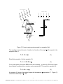
Consider Figure (1). As shown, a loop of wire with a torque arm R is free to rotate
about the z-axis. Rotational torque is defined as
T=F•R
(2)
-1Galil Motion Control, Inc. 3750 Atherton Road Rocklin, CA 95765 USA 800-377-6329 Ph: 916-626-0101 Fax: 916-626-0102 www.galilmc.com
m a g n e t ic f ie ld B
m a g n e t ic f ie ld B
r e s u lt a n t f o r c e F
r e s u lt a n t f o r c e F
w ir e le n g t h L
Y
Y
Z
Z
X
X
d e s ir e d r o t a t io n
c u rre n t I
r a d iu s R
Figure (1) Current-carrying wire exposed to a magnetic field
The resulting torque at the axis of rotation is a function of the angle with respect to the
magnetic field, or
T = F • R sin
(3)
Substituting equation (1a) into equation (3),
T = I • L • B • R sin
(4)
For a given system, the terms R, B, and L are constants. In terms of a DC motor, these
terms can be combined into a common motor constant Kt. This results in equation (5):
T = I • Kt • sin
(5)
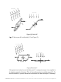
As equation (5) shows, the applied torque will decrease as approaches 0°. Figure (2)
shows the relationship at = 45°.
-2Galil Motion Control, Inc. 3750 Atherton Road Rocklin, CA 95765 USA 800-377-6329 Ph: 916-626-0101 Fax: 916-626-0102 www.galilmc.com
m a g n e t ic f ie ld B
m a g n e t ic f ie ld B
r e s u lt a n t f o r c e F
r e s u lt a n t f o r c e F
Y
d e s ir e d r o t a t io n
Z
Y
X
X
Z
c u rre n t I
Figure (2) Coil at 45°
At = 0° the torque will be effectively 0. See Figure (3).
m a g n e t ic f ie ld B
m a g n e t ic f ie ld B
Y
X
r e s u lt a n t f o r c e F
Z
Y
d e s ir e d r o t a t io n
Z
c u rre n t I
X
r e s u lt a n t f o r c e F
Figure (3) Coil at 0°
If the system has inertia, the coil will drive past 0°, causing the torque to be supplied in
the direction opposite of desired. This will cause the system to oscillate around 0°. To
avoid this situation, a process known as commutation has been developed. Essentially,
-3Galil Motion Control, Inc. 3750 Atherton Road Rocklin, CA 95765 USA 800-377-6329 Ph: 916-626-0101 Fax: 916-626-0102 www.galilmc.com
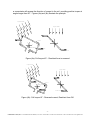
a commutator will reverse the direction of current in the coil, providing positive torque at
angles larger than 90°. Figures (4a) and (4b) illustrate the principle.
m a g n e t ic f ie ld B
m a g n e t ic f ie ld B
Y
c u rre n t I
Z
Y
X
X
Z
d e s ir e d r o t a t io n
r e s u lt a n t f o r c e F
r e s u lt a n t f o r c e F
Figure (4a)- Coil beyond 0° - Resultant force is reversed
m a g n e t ic f ie ld B
m a g n e t ic f ie ld B
Y
r e s u lt a n t f o r c e F
c u rre n t I
Z
Y
X
d e s ir e d r o t a t io n
X
Z
r e s u lt a n t f o r c e F
Figure (4b)- Coil beyond 0° - Reversed current; Resultant force OK
-4Galil Motion Control, Inc. 3750 Atherton Road Rocklin, CA 95765 USA 800-377-6329 Ph: 916-626-0101 Fax: 916-626-0102 www.galilmc.com
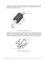
To produce any amount of useable rotational torque, the system design must rely on
multiple current carrying coils of wire to be exposed to the magnetic field B. Figure (5)
shows the physical design of a rotor.
in s u la t in g m a t e r ia l
c u r r e n t c a r r y in g w ir e
w ir e le n g t h L
r a d iu s R
Figure (5)- Basic armature design
In addition to reversing direction of current in the coils, the commutator may also shut
off the current in the coil when they are at an angle near 90°, as the torque produced
may be too small and represent inefficient operation. To perform such a function, the
machine must switch the supply current to these multiple coils based on the rotor angle.
in s u la t in g m a t e r ia l
c o n d u c t iv e m a t e r ia l
b ru s h
c o n n e c t io n t o c o il
Figure (6)- A simple commutator
-5Galil Motion Control, Inc. 3750 Atherton Road Rocklin, CA 95765 USA 800-377-6329 Ph: 916-626-0101 Fax: 916-626-0102 www.galilmc.com
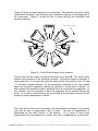
Figure (6) shows the basic elements of a commutator. The machine conductors (which
constitute the windings on the armature) are connected in sequence to the segments of
the commutator. Figure (7) shows the flow of current through the commutator and
armature windings.
2'
2
1'
C lo c k w is e r o t a t io n
3
1
I
3'
I
C u r r e n t in
C u rre n t o u t
4
7'
A
B
4'
7
6'
5
6
5'
Figure (7)- Current flow through a motor armature
Current flows into the system at brush A and flows out at brush B. The small arrows
indicate current direction in the individual coil sides. If the motor rotation is clockwise, it
can be seen that 1/7 of a revolution after the instant shown, the current in coils 3-3’ and
7-7’ will have changed direction. As the commutator continues to turn, the brushes
pass over successive segments, causing the direction of current flow to change. At
some points in the armature rotation, the brush will be in contact with two segments. At
this condition, the coil connected to these two segments will be shorted through the
brush. As a result of this switching, the current flow in the armature occupies a fixed
position in space, independent of rotation.
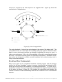
Due to the action of the motor commutator, the armature can be thought of as a wound
core with an axis of magnetization fixed in space. The axis of magnetization is
determined by the rotary position of the brushes. For a motor to have equal
characteristics for both directions of rotation, the axis of magnetization, or brush axis,
-6Galil Motion Control, Inc. 3750 Atherton Road Rocklin, CA 95765 USA 800-377-6329 Ph: 916-626-0101 Fax: 916-626-0102 www.galilmc.com
must be at an angle of 90° with respect to the magnetic field. Figure (8) shows the
resultant axis of magnetization.
M a in f ie ld B
C C W to rq u e
C u r r e n t in
S
C u rre n t o u t
I
I
A x is o f m a g n e t iz a t io n
d e t e r m in e d b y lo c a t io n o f b r u s h e s
C u r r e n t in t o p a g e
C u rre n t o u t o f p a g e
S
C o il s h o r t e d
Figure (8)- Axis of magnetization
The major drawback of a brush-type motor design is the nature of the design itself. The
commutation brush, as a wear item, will eventually need to be replaced. As the brushes
begin to wear, microscopic particles are released, invalidating the motor for use in a
clean room environment. Also, due to the switching of the coils, some electrical arcing
will occur. This rules out brush motors for explosive environments. Otherwise, brushtype motors are inexpensive, reliable, accurate machines that continue to play a role in
today’s industrial workplace.
Brushless Motor Fundamentals
Many motor types can be considered brushless, including stepper and AC-induction
motors, but the term “brushless” is given to a group of motors that act similarly to DCbrush type motors without the limitations of a physical commutator. To review, a DCbrush motor consists of a wound rotor that can turn within the magnetic field as provided
by the stator, as shown in figure (9). By including the commutator and brushes, the
reversal of current is made automatically and the rotor continues to turn in the desired
direction.
-7Galil Motion Control, Inc. 3750 Atherton Road Rocklin, CA 95765 USA 800-377-6329 Ph: 916-626-0101 Fax: 916-626-0102 www.galilmc.com
N
S
C o m m u ta to r
+
-
Figure (9)- A Simple brush-type motor
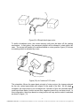
To build a brushless motor, the current-carrying coils must be taken off the rotating
mechanism. In their place, the permanent magnet will be allowed to rotate within the
case. The current still needs to be switched based on rotary position; figure (10) shows
a reversing switch is activated by a cam.
N
S
+
-
R e v e r s in g S w it c h
Figure (10)- An “inside-out” DC motor
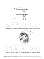
This orientation follows the same basic principle of rotary motors; the torque produced
by the rotor varies trapezoidally with respect to the angle of the field. As the angle
increases, the torque drops to an unusable level. Because of this, the reversible switch
could have three states: positive current flow, negative current flow, and open circuit. In
this configuration, the torque based on rotary position will vary as the current is switched
as shown in figure (11).
-8Galil Motion Control, Inc. 3750 Atherton Road Rocklin, CA 95765 USA 800-377-6329 Ph: 916-626-0101 Fax: 916-626-0102 www.galilmc.com
Kt (
)
C u rre n t I
0°
180°
360°
T o rq u e T
Figure (11)- Single-phase torque based on rotary position
In this model, the Torque T is the product of the theoretical motor constant Kt times the
supplied current I. In a single pole system such as this, useable torque is only produced
for 1/3 of the rotation. To produce useful torque throughout the rotation of the stator,
additional coils, or “phases” are added to the fixed stator. Figure (12) shows a simple
three-phase brushless motor.
C ase
R o to r
N
H a ll- e f f e c t s e n s o r
S
C o il
Figure (12)- Basic three-phase, 2-pole brushless motor
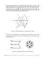
The key to effective motion is to switch the current in all three phases based on rotor
position. The use of a physical switch is prohibited because of the timing requirements.
Instead, a digital device known as a Hall-effect sensor is used. Typically, three Hall
sensors are placed at 120° apart around the case of the motor. Based on the magnetic
field produced by the rotor, the combination of the three logic signals can determine the
location of the rotor to within 60°. From this information, the commutator switches
-9Galil Motion Control, Inc. 3750 Atherton Road Rocklin, CA 95765 USA 800-377-6329 Ph: 916-626-0101 Fax: 916-626-0102 www.galilmc.com
current flow between phases. This keeps the stator field ahead of the rotor. The
desired lead angle is 90°, but because of the limitation of having only three phases, the
effective lead angle will vary between 60° and 120°. Figure (13) shows the rotor at a
Hall transition point. Up until = 60°, the commutator causes the stator field to be
oriented along vector A. At > 60°, the commutator advances the field to point B. The
average of this field switching is therefore maintained at 90°.
D e s ir e d r o t a t io n
S
S t a t o r f ie ld B
N
1 2 0 .0 °
6 0 .0 °
S t a t o r f ie ld A
R o t o r f ie ld
Figure (13)- Stator field orientation vs. perceived rotor location
Another aspect of the brushless motor technology is that current flows into one coil and
out another. The direction of the current flow is based on position, determined by the
Hall-effect sensors.
I
A
A1
A1
C2
B2
I
B
B1
B2 A2
S
N
C2
I
B1
C1
C
C1
A2
Figure (14)- 3 Phase brushless motor current schematic
- 10 Galil Motion Control, Inc. 3750 Atherton Road Rocklin, CA 95765 USA 800-377-6329 Ph: 916-626-0101 Fax: 916-626-0102 www.galilmc.com
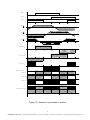
It becomes apparent that the sum of the current flowing into and out of the system must
be zero; thus, if IA is positive, either IB or IC must be negative. Figure (15) details the
relationship between the Hall-effect sensors, the subsequent switching of current in the
coils, and the resultant applied torque.
- 11 Galil Motion Control, Inc. 3750 Atherton Road Rocklin, CA 95765 USA 800-377-6329 Ph: 916-626-0101 Fax: 916-626-0102 www.galilmc.com
H a ll 1
1
H a ll 2
1
H a ll 3
1
0
0
0
0°
Kt (
60°
120°
180°
210°
300°
360°
300°
360°
)
A
Kt (
)
B
Kt (
)
210°
C
0°
60°
120°
180°
60°
120°
180°
210°
300°
360°
60°
120°
180°
210°
300°
360°
+
C u rre n t I
A
0°
-
+
C u rre n t I
B
-
+
C u rre n t I
C
-
A p p lie d T o r q u e
P hase A
P hase B
P hase C
R e s u lt a n t T o r q u e
0°
Figure (15)- Resultant torque based on position
- 12 Galil Motion Control, Inc. 3750 Atherton Road Rocklin, CA 95765 USA 800-377-6329 Ph: 916-626-0101 Fax: 916-626-0102 www.galilmc.com
As can be seen, the digital state of the three Hall-effect sensors can determine the rotor
position within 60 degrees. For example, a reading is taken where Hall 1= high (1), Hall
2= low (0) and Hall 3= high (1). This combination 101 places the rotor at 60°< <120°.
This being true, the commutator sets the current flow into phase A (positive current) and
out of phase B (negative current). The applied torque by each phase is the product of
the motor constant Kt and the current I. At 60°< <120°,
Kt(A) (positive) * IA (positive) = TA (positive)
Kt(B) (negative) * IB (negative) = TB (positive)
(6)
Kt(C) (indeterminate) * IB (zero) = TB (zero)
The sum of TA + TB + TC is shown on the final line. For this model, assume perfect
symmetry in the phases,
Kt(motor) = Kt(A) = Kt(B) = Kt(C)
Imotor = IA = IB = IC
(7)
At any given angle , the applied torque as measured on the rotor shaft is
Tmotor = 2* Kt(motor) * Imotor
(8)
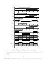
However, in a real system, the impedances of the coils will most certainly differ, albeit
slightly. The motor constant and applied current can vary by several percent and still be
within manufacturer’s tolerance. As a test, consider that every parameter is perfect with
the exception of the motor constant on phase C. As such, at certain points, the
resultant torque will vary similar to Figure (16).
- 13 Galil Motion Control, Inc. 3750 Atherton Road Rocklin, CA 95765 USA 800-377-6329 Ph: 916-626-0101 Fax: 916-626-0102 www.galilmc.com
H a ll 1
1
H a ll 2
1
H a ll 3
1
0
0
0
0°
Kt (
60°
120°
180°
210°
120°
180°
210°
300°
360°
300°
360°
)
A
Kt (
)
B
Kt (
)
C
0°
60°
+
C u rre n t I
A
0°
-
60°
120°
180°
210°
300°
360°
60°
120°
180°
210°
300°
360°
+
C u rre n t I
B
-
+
C u rre n t I
C
-
A p p lie d T o r q u e
P hase A
P hase B
P hase C
R e s u lt a n t T o r q u e
0°
Figure (16)- Resultant shaft torque with a weak phase C
This phenomenon is commonly known as torque ripple, and is most noticeable at low
speeds.
- 14 Galil Motion Control, Inc. 3750 Atherton Road Rocklin, CA 95765 USA 800-377-6329 Ph: 916-626-0101 Fax: 916-626-0102 www.galilmc.com
If a brushless motor relies on the state of Hall-effect sensors to commutate the phases,
the current flowing in a coil can have three discreet states. Current can flow into the
coil, out of the coil, or no current can flow. The general form of the equation for torque
with respect to rotor position within the magnetic field is
TA = IA * Kt(A) * sin
(9)
If the position of the rotor is 90°, the supplied current is completely converted into shaft
torque. As the rotor position moves away from 90°, the term diminishes the overall
available torque. As shown earlier, the state of the current IA will change at =60°. But
at =60°, the torque is IA * Kt(A) * 0.866. This states that only 87% of the current is
utilized. The current not converted into torque is wasted as heat.
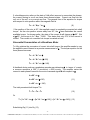
Sinusoidal Commutation of a Brushless Motor
To fully optimize the conversion of current into shaft torque, the amplifier needs to vary
the applied current I based on a precise measurement of . The torque equation for the
three phases becomes
TA = IA * Kt * sin
TB = IB * Kt * sin (+120)
(10)
TC = IC * Kt * sin ( + 240)
A feedback device such as a quadrature encoder can determine in terms of counts;
a common resolution is 360° (1 revolution) = 4000 counts. The amplifier varies the
current in each phase I based on the motor command signal M with respect to :
IA = M * sin
IB = M * sin (+120)
(11)
IC = M * sin ( + 240)
The total perceived shaft torque T is
T = TA + TB + TC
(12)
Or
T = [ IA * Kt * sin ] + [IB * Kt * sin (+120)] + [IC * Kt * sin ( + 240)] (13)
Substituting Eq.(11) into Eq.(13),
- 15 Galil Motion Control, Inc. 3750 Atherton Road Rocklin, CA 95765 USA 800-377-6329 Ph: 916-626-0101 Fax: 916-626-0102 www.galilmc.com
T = [{M * sin } * Kt * sin ] + [{M * sin (+120)} * Kt * sin (+120)]
+ [{= M * sin ( + 240)} * Kt * sin ( + 240)]
(14)
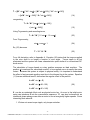
reorganizing,
T = Kt * M * [sin2 + {sin2 ( + 120)}
+ {sin2 ( + 240)}]
(15)
Using Trigonometry and canceling terms,
T = Kt * M * [1.5 sin2 + 1.5 cos2]
(23)
From Trigonometry,
sin2 + cos2 = 1
(24)
T = 3/2 * Kt * M
(25)
Eq. (23) becomes
For a full derivation, refer to Appendix A. Equation (25) states that the torque supplied
to the rotor shaft is no longer a function of rotor angle. Torque ripple is all but
eliminated and the system has linear characteristics quite similar to a conventional DC
brush motor.
The calculation of torque based on rotary position assumes an ideal machine. The
position is read and the calculated current I to be supplied occur at exactly the same
instant. Because this system is subject to physical reality, it is important to understand
the effect of an inaccurate position read due to the inherent lag in the system. Equation
(11) has an additional term Є, defined as the angular offset in the position.
IA = M * sin ( + Є)
IB = M * sin (+ Є+ 120)
(26)
IC = M * sin (+ Є + 240)
Є can be an undesired offset such as physical motor lag. An error in the initial motor
setup can introduce Є into the commutation sequence. Є can also be beneficial; an
intentional phase advance can allow a motor to turn at marginally higher speeds. Some
interesting facts about Є:
1. Є does not cause torque ripple, only torque reduction.
- 16 Galil Motion Control, Inc. 3750 Atherton Road Rocklin, CA 95765 USA 800-377-6329 Ph: 916-626-0101 Fax: 916-626-0102 www.galilmc.com
2. If |Є| < 10°, the effect on the torque is minimal. This makes the initial phase
positioning non-critical.
3. When Є is very large (>60°), Kt is cut in half. (Cos 60°=0.5) For the motor to
perform a specified amount of work, it will require twice the current. Power
dissipation will increase 4X. This situation will probably burn the motor. A
thermal sensor is a good safeguard against overheating.
4. If Є =90°, there will be zero torque. Current draw will be normal, but all the
energy is converted to heat. A burned motor is a near certainty.
5. If 90° < Є < 270°, the polarity of the current is reversed. Positive feedback and
wild oscillations will occur.
Working Eq. (26) through,
T = 3/2 * Kt * M * cos Є
(27)
This shows that Є values over 15° cause a drastic decrease in the available torque. To
compensate, the motor will draw excessive current and could burn the motor. At very
high values of Є, the motor can actually overdrive the circuitry and enter a mode called
positive feedback. Such a state can cause catastrophic failure.
In any given system, the perceived lag will increase as the angular velocity increases.
An intelligent drive system can force Є into a slightly positive state, much as the vacuum
advance on an automobile distributor accounts for mistimed spark plug charge due to
high RPM.
As with trapezoidal, a sinusoidal commutation amplifier relies on the torque constant Kt
being identical in all phases. Rarely is this absolutely true; to minimize any torque
ripple, most drives allow a user to vary the amplitude or offset of one or more phases.
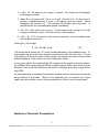
Methods of Sinusoidal Commutation
- 17 Galil Motion Control, Inc. 3750 Atherton Road Rocklin, CA 95765 USA 800-377-6329 Ph: 916-626-0101 Fax: 916-626-0102 www.galilmc.com
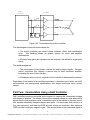
There are two common methods of varying the current supplied to the motor windings.
The historical method has relied on the amplifier to divide the current based on
feedback and supply the motor, as shown in figure (17):
I
M o t io n
+1 0 V
-
C o n t r o lle r
C o m m u t a t in g
I
A
B
A1
B1
A m p lif ie r
B2 A2
C2
I
C
C1
Figure (17)- A Commutating amplifier
The benefits of this method of commutation are:
Ease of setup- simply apply a motor command signal
No initialization needed- the amp commutates based on Hall state
The disadvantages are:
Lack of flexibility- the amp and motor are usually paired; a brushless motor with
a different commutation cycle or Hall angles render the amplifier incompatible
Difficult to tune - If there is an offset in one or more of the phases, quite often
the only method to equalize phases is a potentiometer
The amplifier may contain a velocity loop. This effect may interfere with the
operation of the controller, and must be taken into account during axis tuning
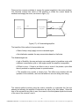
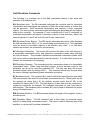
The second method involves using the motion controller to commutate the first two
phases and allowing the amplifier to determine the value of the third phase. Since the
sum of the currents at any time is zero, the current in the third phase equals the inverse
of the sum of the currents Ia and Ib.
- 18 Galil Motion Control, Inc. 3750 Atherton Road Rocklin, CA 95765 USA 800-377-6329 Ph: 916-626-0101 Fax: 916-626-0102 www.galilmc.com
M o t io n
A m p lif ie r
C o n t r o lle r
M
M
I
A
I
B
A
B
A1
B1
B2
A1
C2
I
C
C1
-1
Figure (18)- Commutation by motion controller
The advantages of controller commutation are:
The motion controller can control phase advance, offset, and commutation
cycle.
This flexibility allows far greater options for motor and amplifier
combinations
All control loop gains are calculated on the controller; this allows for single-point
tuning
The disadvantages are:
The commutation of two phases requires two analog output signals. On many
motion controllers, this requires a second axis for each brushless amplifier,
increasing the cost of the controller
A brushless setup routine is required for the controller to determine the phasing
Regardless of the method of sinusoidal commutation, a brushless servo motor can fulfill
environmental and performance specifications that simple brush-type servo motors
cannot.
Part Two: Commutation Using a Galil Controller
Galil controllers produce sinusoidal motor signals by varying the commanded voltage
with respect to position. The shape of the motor command voltage is a sine wave with a
period equal to one brushless cycle. A brushless cycle is the number of encoder counts
that separate identically charged magnetic pole pairs. If it was known that a motor is a
four pole pair motor, and there are 4000 encoder counts per revolution, then there are
1000 encoder counts per magnetic cycle. The second phase of the command signal is
- 19 Galil Motion Control, Inc. 3750 Atherton Road Rocklin, CA 95765 USA 800-377-6329 Ph: 916-626-0101 Fax: 916-626-0102 www.galilmc.com
simply offset by 120 degrees. The third phase, which is the inverse of the sum of the
first two phases, is usually determined by the amplifier.
Before the Galil controller is able to perform this commutation, a minimum of three setup
commands must be given. The first indicates what axis is to be commutated as
brushless, the second command sets the brushless modulus, and the third defines the
0 position. From there, the Galil controller is able to commutate based on the incoming
encoder feedback.
Brushless phase resolution and frequency
M o t o r C o m m a n d m a g n it u d e , V o lt s
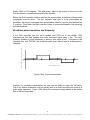
If the Galil controller has the servo update time (TM) set to the default 1000
microseconds, the Galil updates the motor command signal every 1 ms. The bare
minimum number of points necessary to define a sine wave is four. This leads to the
limitation that, with TM1000, the brushless cycle must take at least 4 milliseconds to
complete.
+
0°
-
60°
120°
180°
210°
300°
360°
B r u s h le s s D e g r e e s
Figure (19a)- 4 point commutation
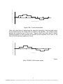
However, for smoother commutation, the user has the ability to lower the TM value.
This is not without drawbacks, but can quickly lead to a much smoother sine wave at a
given motor frequency. Figure (19b) shows the command voltage based on an update
time of 500 microseconds.
- 20 Galil Motion Control, Inc. 3750 Atherton Road Rocklin, CA 95765 USA 800-377-6329 Ph: 916-626-0101 Fax: 916-626-0102 www.galilmc.com
M o t o r C o m m a n d m a g n it u d e , V o lt s
+
0°
-
60°
120°
180°
210°
300°
360°
B r u s h le s s D e g r e e s
Figure (19b)- 8 point commutation
M o t o r C o m m a n d m a g n it u d e , V o lt s
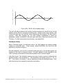
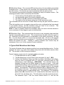
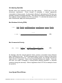
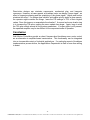
Often, the critical factor in determining the maximum frequency of the sinusoidal output
will be determined by the voltage that is supplied to the amplifier. The voltage usually
defines the maximum rpm of the motor. Figures (20a) and (20b) show a drastic
difference between a Galil controller at TM1000 and the amplifier at 24 Volts vs. the
Galil at TM125 and the amplifier at 48 Volts.
+
0
-
2
4
8
6
10
12
T im e , m s
Figure
(20a)- TM1000, 24 Volt power supply
- 21 Galil Motion Control, Inc. 3750 Atherton Road Rocklin, CA 95765 USA 800-377-6329 Ph: 916-626-0101 Fax: 916-626-0102 www.galilmc.com
M o t o r C o m m a n d m a g n it u d e , V o lt s
+
0
-
2
4
6
8
10
12
T im e , m s
Figure (20b)- TM125, 48 Volt power supply
The user will want to balance the number of points necessary for smooth motion on the
specific system with the command processing time. System inertia, motor velocity, and
overall loop gain play an important role in determining the minimum TM value that is
required. Note that changing the TM value requires recalibration of almost all
parameters; speed, acceleration, derivative gain and many others are functions of the
TM value. For Galil commutation specifications, see Appendix B.
Hardware Setup
Motor Command signal- As mentioned before, the Galil requires two analog voltage
signals per sinusoidal axes. These signals, labeled MOCMDn, are wired into the
amplifier’s Command Voltage In.
Encoder feedback- Just as with a standard brush-type servo, the encoder signals are
required for the Galil to command motion. Encoder feedback is also required for the
Galil to properly commutate the sinusoidal brushless motor command signal.
Hall-effect inputs- The Hall-effect sensors are used in many motors to determine the
physical location of the brushless 0. The Hall-effects are usually offset at 0, 30, or
90. If the offset is not known, it can be determined during the brushless setup. Halleffect sensors are not required for accurate commutation.
- 22 Galil Motion Control, Inc. 3750 Atherton Road Rocklin, CA 95765 USA 800-377-6329 Ph: 916-626-0101 Fax: 916-626-0102 www.galilmc.com
Galil Brushless Commands
The following is a complete list of the Galil commands relating to the setup and
operation of a brushless axis.
BA (Brushless Axis): The BA command configures the controller axes for sinusoidal
commutation and reconfigures the controller to reflect the actual number of motors that
can be controlled. Each sinusoidal commutation axis requires 2 motor command
signals. The second motor command signals will always be associated with the highest
axes on the controller. For example a 3 axis controller with X and Z configured for
sinusoidal commutation will require 5 command outputs (5 axes controller), where the
second outputs for X and Z will be the W and E axes, respectively.
BB (Brushless Phase Begins): The BB function describes the position offset between
the Hall transition point and = 0, for a sinusoidally commutated motor. This command
must be saved in non-volatile memory to be effective upon reset. If no Hall-effect
sensors are present, this command is not necessary.
BC (Brushless Calibration): The function BC monitors the status of the Hall sensors of
a sinusoidally commutated motor, and resets the commutation phase upon detecting
the first hall sensor. This procedure replaces the estimated commutation phase value
with a more precise value determined by the hall sensors. If no Hall-effect sensors are
present, this command is not necessary.
BD (Brushless Degrees): This command sets the commutation phase of a sinusoidally
commutated motor. When using Hall-effect sensors, a more accurate value for this
parameter can be set by using the command, BC. The user can query the current
brushless degree value by issuing a BD? . This command should only be used when
the user is creating a specialized phase initialization procedure.
BI (Brushless Inputs): The command BI is used to define the inputs that are used when
Hall sensors have been wired for sinusoidally commutated motors. These inputs can be
the general use inputs (bits 1-8), the auxiliary encoder inputs (bits 81-96), or the
extended I/O inputs (bits 17-80). The Hall sensors of each axis must be connected to
consecutive input lines, for example: BI 3 indicates that inputs 3,4, and 5 are used for
halls sensors. The brushless setup command, BS, can be used to determine the proper
wiring of the hall sensors.
BM (Brushless Modulo): The BM command defines the length of the magnetic cycle in
encoder counts.
BO (Brushless Offset): The BO command sets a fixed offset on command signal
outputs for sinusoidally commutated motors. This may be used to offset any bias in the
amplifier, or can be used for phase initialization.
- 23 Galil Motion Control, Inc. 3750 Atherton Road Rocklin, CA 95765 USA 800-377-6329 Ph: 916-626-0101 Fax: 916-626-0102 www.galilmc.com
BS (Brushless Setup): The command BS tests the wiring of a sinusoidally commutated
brushless motor. If Hall sensors are connected, this command also tests the wiring of
the Hall sensors. This function can only be performed with one axis at a time.
This command returns status information regarding the setup of brushless motors. The
following information will be returned by the controller:
1. Correct wiring of the brushless motor phases.
2. An approximate value of the motor's magnetic cycle.
3. The value of the BB command (If Hall sensors are used).
4. The results of the hall sensor wiring test (If Hall sensors are used).
This command will turn the motor off when done and may be given when the motor is
off.
Once the brushless motor is properly setup and the motor configuration has been saved
in non-volatile memory, the BS command does not have to be re-issued. The
configuration is saved by using the burn command, BN.
Note: In order to properly conduct the brushless setup, the motor must be allowed to
move a minimum of one magnetic cycle in both directions.
BZ (Brushless Zero): This command drives the motor to zero magnetic phase and then
sets the commutation phase to zero. This command may be given when the motor is
off. Essentially, the BZ command is a combination of two earlier commands: BO and
BD. If a user issues a BO of +1 unit on the first phase and –1/2 unit on the second
phase, the motor should move to brushless 0. From there, the user can issue a BD0 to
define this position as zero. Creating a custom brushless zero routine may be
necessary in low- or no- friction systems to avoid oscillation.
A Typical Galil Brushless Axis Setup
This section illustrates how an operator would set up a normal brushless motor. For this
example, the motor is a 4 pole, three phase rotary motor with Hall-effect sensors offset
60°. The encoder is 4000 counts per revolution.
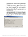
Figure 6 shows a screen shot of a typical brushless axis setup.
1. The Brushless Axis is set to Z. (BAZ)
2. The Brushless Input on the Z-axis is given as inputs 5,6, and 7. (BI5)
3. Perform the Brushless Setup and test for polarity, Hall-effects, and offsets.
Here the motor is energized with a 2 Volt motor command signal for 200
milliseconds in both directions. (BSZ=2,200) The controller returns the
statement ‘Wiring from the ACMD signals to the amp is correct.’ If this had
stated that the wiring ‘must be reversed’, the operator would swap the motor
command for the first phase with the motor command signal for the second
phase. The statement ‘The Brushless Modulus (BM) is approximately 1001’
is redundant in this case. If the operator had an unknown brushless modulus,
the controller returns an approximate value. The statement ‘The Brushless
phase offset (BB) should be set to 60°’ states that the Hall-effect sensors are
off set 60° from brushless zero. This information was also previously known.
The statement ‘Input 7 has the correct sensor wired to it’ and the two
- 24 Galil Motion Control, Inc. 3750 Atherton Road Rocklin, CA 95765 USA 800-377-6329 Ph: 916-626-0101 Fax: 916-626-0102 www.galilmc.com
4.
5.
6.
7.
following alert the operator to a legal Hall state. If the Hall sensors were
undetermined, the user could rewire based on the suggestion and retry the
brushless setup.
The Brushless Modulus is set to 1000. (BM,,1000) This explicitly sets the
known Brushless Modulus to 1000 counts per brushless cycle.
The Brushless Offset is set to 60 (BB,,60). As stated, the Hall effect
sensors must have an offset assigned. Some motors will have offsets of
120°.
Drive the axis to Brushless Zero. (BZ,,-1) This statement drives the
brushless axis to theoretical brushless 0° by hitting phase A with 1 Volt and
phase B with -1/2*(phase A). A negative number causes the axis to stay in
the Servo Here(SH) state.
Query the current Brushless Degree (BD,,?). The response, 2.88, is within
untuned tolerance. If this number was greater than expected, try issuing a
larger voltage on the BZ command. If the motor his high friction or heavy
inertia, 1 Volt may not have been enough to drive the motor to an accurate
reading of brushless zero. If the system oscillates and times out, increase the
BZ timeout by adding a ‘<n’ in the second field. See the Command
Reference for details.
Figure (21)- Brushless motor setup
- 25 Galil Motion Control, Inc. 3750 Atherton Road Rocklin, CA 95765 USA 800-377-6329 Ph: 916-626-0101 Fax: 916-626-0102 www.galilmc.com
Part Three: Application Examples
Brushless motor technology can be found in a variety of applications, including linear
motors, high-rpm air-bearing spindles, and low-speed direct drives. Included here are a
few tips and tricks for setting up these systems to run with a Galil Motion Controller.
Linear Motors
Linear brushless motors are essentially a rotary motor that lays flat. The stage acts like
the stator, while the case magnets are laid sequentially along the track. Setup and
configuration are very similar to rotary motors, however, linear motors are capable of
producing immense amount of torque, and, due to physical design, cannot run freely
like a rotary motor can. Extreme caution should be taken during initialization. Ensure
working limit switches, if available, before applying power to the motor. Before any
commands are issued, the operator must fully understand the functions and
consequences of what is typed. A common safety routine such as the following might
be incorporated into an X-axis initialization:
:MO
‘Disables amplifiers
:OF0
‘Sets offset bias to zero
:KP1
‘Sets proportional gain to 1
:KD5
‘Sets derivative gain to 5
:KI0
‘Sets integral gain to 0
:TL.5
‘Sets maximum output voltage to .5 volts (5% of max)
:ER1000
‘Sets error limit to 1000
:ER1
‘Enable Off-on-Error function
**At this point, apply power to the amplifier. The motor should not move (MO)
:SHX
‘Enable X-axis
**This command enables the axis. Be fully aware of any safety considerations before
attempting this. After the axis is enabled, the stage should not move. The TE (Tell
Error) command should return a reasonable amount of error. If the stage jumped,
check the error. If it is greater than 1000(in this case) the axis ran away until the Off-onError shut the axis down. Check encoder polarity, noise, or dead shorts. Once the
motor remains stable, the user is ready to perform the standard brushless motor setup
as discussed previously.
- 26 Galil Motion Control, Inc. 3750 Atherton Road Rocklin, CA 95765 USA 800-377-6329 Ph: 916-626-0101 Fax: 916-626-0102 www.galilmc.com
Air-bearing Spindles
Spindle motors are commonly used at very high velocity.
10,000 rpm is not an
uncommon requirement.
Some thought is necessary to ensure appropriate
commutation at these speeds. As discussed in Section 2, decreasing the TM value can
markedly increase sinusoidal resolution. Note that all time-based commands will have
their apparent values modified if the TM is not default. To calculate the maximum rpm
and counts/second, apply the following equations:
Max Rotational Velocity (RPM):
X ( RPM )
60 sec
*
1000 m sec
1 min
1 magnetic
*
1 sec
(# of _ desired
_ cycle
_ samples
6 * 10
X ( RPM )
(# mag _ cycles
*
)
1 Re v
*
# of _ mag _ cycles
1
TM ( sec)
*
1000 sec
1 m sec
7
/ rev ) * ( TM ) * (# of _ desired
(28)
_ samples
)
Max Commanded Velocity:
max_
velocity
counts
sec
(# counts / mag _ cycle ) * 10
TM * (# desired
_ samples )
6
(29)
Air bearings, with their minimal inherent friction, present a somewhat unique dilemma
when initializing the axis. The BZ command relies on friction to damp out the motion
before the command times out. If the axis constantly times out, increase the timeout
value with the <t argument. Refer to the Command Reference for details. If the axis
still does not settle, investigate a velocity-based damping algorithm to minimize
overshoot during the axis setup. Refer to Application Note 3413 for an example of such
an operation.
Low-Speed Direct Drives
- 27 Galil Motion Control, Inc. 3750 Atherton Road Rocklin, CA 95765 USA 800-377-6329 Ph: 916-626-0101 Fax: 916-626-0102 www.galilmc.com
Direct-drive designs can minimize components, mechanical play, and harmonic
resonance. However, at lower speeds, a brushless motor can display “torque ripple”, an
effect of imprecise phasing and the quantizing of the phase signal. Higher-end motors
minimize this effect. If a design does exhibit a noticeable velocity ripple at slow speeds,
the operator might consider two things: lower the PID settings to 75% of their original
values. Does this improve or exacerbate the situation? A second and more drastic step
is to increase the TM value, making the servo update time larger. Again, keep in mind
the TM value affects almost all the system parameters. If torque ripple is still present,
the specified amplifier may be insufficient for the requested mode of operation.
Conclusion
Galil Motion Controllers provide a robust, firmware-level brushless servo motor control
as an alternative to amplifier-based commutation. This functionality can be integrated
into an innumerable variety of industrial applications. If a particular aspect of brushless
implementation proves elusive, the Applications Department at Galil is more than willing
to assist.
- 28 Galil Motion Control, Inc. 3750 Atherton Road Rocklin, CA 95765 USA 800-377-6329 Ph: 916-626-0101 Fax: 916-626-0102 www.galilmc.com
Appendix A
Complete derivation of shaft torque based on rotor position
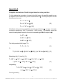
To fully optimize the conversion of current into shaft torque, the amplifier needs to vary
the applied current I based on a precise measurement of . The torque equation for the
three phases becomes
TA = IA * Kt * sin
TB = IB * Kt * sin (+120)
(10)
TC = IC * Kt * sin ( + 240)
A feedback device such as a quadrature encoder can determine in terms of counts;
a common resolution is 360° (1 revolution) = 4000 counts. The amplifier varies the
current in each phase I based on the motor command signal M with respect to :
IA = M * sin
IB = M * sin (+120)
(11)
IC = M * sin ( + 240)
The total perceived shaft torque T is
T = TA + TB + TC
(12)
Or
T = [ IA * Kt * sin ] + [IB * Kt * sin (+120)] + [IC * Kt * sin ( + 240)] (13)
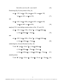
Substituting Eq.(11) into Eq.(13),
T = [{M * sin } * Kt * sin ] + [{M * sin (+120)} * Kt * sin (+120)]
+ [{= M * sin ( + 240)} * Kt * sin ( + 240)]
(14)
reorganizing,
T = Kt * M * [sin2 + {sin ( + 120)* sin ( + 120)}
+ {sin ( + 240)* sin ( + 240)}]
(15)
From trigonometry,
- 29 Galil Motion Control, Inc. 3750 Atherton Road Rocklin, CA 95765 USA 800-377-6329 Ph: 916-626-0101 Fax: 916-626-0102 www.galilmc.com
Sin (A+B) = sin A cos B + cos A sin B
(16)
Substituting Eq.(16) into portions of Eq.(15)
sin ( + 120) * sin ( + 120)= (sin cos 120 + cos sin 120)
* (sin cos 120 + cos sin 120)
(17)
and
sin ( + 240) * sin ( + 240)= (sin cos 240 + cos sin 240)
* (sin cos 240 + cos sin 240)
(18)
applying F-O-I-L and adding numeric values to Eq. (17) and (18):
sin ( + 120) * sin ( + 120)= .25 sin 2 + (-.5sin )(.866cos)
+ (-.5sin )(.866cos) + .75cos2
(19)
and
sin ( + 240) * sin ( + 240)= .25 sin 2 + (-.5sin )(-.866cos)
+ (-.5sin )(-.866cos) + .75cos2
(20)
substituting Eq. (19) and (20) back into Eq. (15):
T = Kt * M * [sin2 + .25 sin 2 + (-.5sin )(.866cos)
+ (-.5sin )(.866cos) + .75cos2 + .25 sin 2
+ (-.5sin )(-.866cos) + (-.5sin )(-.866cos) + .75cos2
(21)
canceling terms:
T = Kt * M * [sin2 + .25 sin 2 + .75cos2 + .25 sin 2 + .75cos2
(22)
- 30 Galil Motion Control, Inc. 3750 Atherton Road Rocklin, CA 95765 USA 800-377-6329 Ph: 916-626-0101 Fax: 916-626-0102 www.galilmc.com
And
T = Kt * M * [1.5 sin2 + 1.5 cos2]
(23)
From Trigonometry,
sin2 + cos2 = 1
(24)
T = 3/2 * Kt * M
(25)
Eq. (23) becomes
- 31 Galil Motion Control, Inc. 3750 Atherton Road Rocklin, CA 95765 USA 800-377-6329 Ph: 916-626-0101 Fax: 916-626-0102 www.galilmc.com
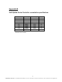
Appendix B
Galil Optima Series Controller commutation specifications
Number of axes
1-8
7-8
7-8
5-6
5-6
3-4
3-4
1-2
1-2
Time step
TM1000
TM625
TM500*
TM500
TM375*
TM375
TM250*
TM250
TM125*
Brushless cycle # of points
4 ms
4
4 ms
6
2 ms
4
4 ms
8
4 ms
10
2 ms
5
4 ms
12
2 ms
6
4 ms
24
* Indicates Fast Firmware
- 32 Galil Motion Control, Inc. 3750 Atherton Road Rocklin, CA 95765 USA 800-377-6329 Ph: 916-626-0101 Fax: 916-626-0102 www.galilmc.com
References
1. DC Motors, Speed Controls, Servo Systems , Various authors. Electro-Craft
Corporation, Hopkins, MN 55343. pp 2.1-2.37 & 6.1-6.21
2. Command Reference, Optima Series, Various authors. Galil Motion Control,
Rocklin, CA 95765
3. User Manual, Optima Series, Various authors. Galil Motion Control, Rocklin, CA
95765. pp 2.20-2.22 & A175-A177
- 33 Galil Motion Control, Inc. 3750 Atherton Road Rocklin, CA 95765 USA 800-377-6329 Ph: 916-626-0101 Fax: 916-626-0102 www.galilmc.com