1
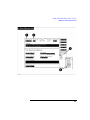
This Software Is Used With the HP 8920B Opt. 500,
HP 8921A Option 500, HP 8920D, or HP 8921D
HP 11807A,E Option 009
NA Dual-Mode Cellular Mobile Test Software
User’s Guide
HP Part No. 11807-90124
Printed in U. S. A.
March 1996
Fourth Edition (Rev D)
1
Copyright © Hewlett-Packard Company 1994, 1995, 1996
RESTRICTED
Use, duplication or disclosure by the U. S. Government is subject to
RIGHTS LEGEND restrictions as set forth in subparagraph (c) (1) (ii) of the Rights in
Technical Data and Computer Software Clause in
DFARS 252.227-7013.
Hewlett-Packard Company
3000 Hanover Street
Palo Alto, CA 94304
U.S.A
Rights for non-DOD U. S. Government Departments and Agencies are
as set forth in FAR 52.227-19 (c) (1, 2).
2
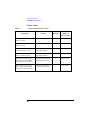
Table of Contents
Contents
1 Getting Started with FW Above Rev. A.14.00
What You Will Test 16
The Test Set or Test System is Defined As:
Equipment Needed to Get Started 17
18
17
Test System Overview 19
Setup and Insert Software Card 20
Select the Tests from the Card 22
Make Connections 25
Enter Mobile Unit’s Control Channel 26
Run the Tests 28
2 Getting Started with FW Below Rev. A.14.00
What You Will Test 32
The Test Set or System is Defined As: 33
Equipment Needed to Get Started 33
34
Test System Overview 35
Setup and Insert Software Card 36
Select the Tests from the Card 38
3
Contents
Make Connections 41
Enter Mobile Unit’s Control Channel 42
Run the Tests 44
3 Product Description
HP 11807A,E Software 48
Items Included in the HP 11807A,E Option 009 Software
Software Function 48
Software Features 48
Equipment Needed 49
Finding the Information You Need 52
Additional Services Available 54
4 Making Connections
Equipment Connections 56
Mobile Unit to Test System Connection
Damage to Equipment 56
Audio Connections 57
Cables and Connectors 58
Printer Cables 60
Calibrating Cable Loss 61
4
56
48
Contents
5 Using the Software HP 8920B, or HP 8920A FW Above Rev.
A.14.00
Testing Overview 66
Running Tests Overview 67
Before Running Tests 68
Selecting a Test Procedure 69
Selecting A Test Procedure 70
Customizing Testing 71
How to Customize Testing 72
Changing the Order of Tests 72
How to Change the Order of Tests 74
Specifying Channel Information 77
How to Specify Channel Information 81
Changing Pass/Fail Limits 84
How to Change Pass/Fail Limits 84
Changing the Test Parameters 87
How to Change the Test Environment and Conditions
Saving a Test Procedure 89
How to Save a Test Procedure 90
Changing Test Execution Conditions 93
How to Change Test Execution Conditions 94
Printing and Saving Test Results 95
87
6 Using the Software HP 8920A FW Below Rev A.14.00
Running Tests Overview 100
Before Running Tests
101
5
Contents
Running Tests 101
Loading a Software Upgrade, FW below rev A.12.04 only
101
Selecting a Test Procedure 103
Customizing the Software 104
Beginning Software Customization 106
Changing the Order of Tests (Edit Sequence) 107
How to Change a Sequence of Tests 108
Specifying Channel Information (Edit Frequency) 111
How to Specify Channel Information 115
Changing Pass/Fail Limits (Edit Specifications) 117
How to Change Pass/Fail Limits 117
Changing the Test Environment and Conditions (Edit Parameters)
How to Change the Test Environment and Conditions 120
Saving a Test Procedure Using the Procedure Manager 122
How to Save a Test Procedure 123
Changing Test Execution Conditions 126
How to Change Test Execution Conditions 127
Printing and Saving Test Results 127
120
7 Test, Parameter, and Pass/Fail Limit (Specification) Descriptions
Testing Strategy 130
Test Descriptions 133
Standards Used 133
Test Nomenclature 133
TEST_01 - CP Registration 134
TEST_02 - CPA Page 135
TEST_03 - TXA Frequency Error
6
136
Contents
TEST_04 - TXA RF Power Output 137
TEST_05 - TXA Modulation Deviation Limiting 139
TEST_06 - TXA Audio Frequency Response 141
TEST_07 - TXA Audio Distortion 142
TEST_08 - TXA Signaling Tone/DST 143
TEST_09 - TXA FM Hum and Noise 145
TEST_10 - TXA SAT/DSAT 146
TEST_11 - TXA RVC Data Deviation 148
Pass/Fail Limits Used 150
Test Parameters Used 150
TEST_12 - TXA Compressor Response 151
TEST_13 - TXA Current Drain 153
TEST_14 - RXA Expandor 156
TEST_15 - RXA Audio Frequency Response 158
TEST_16 - RXA Audio Distortion 159
TEST_17 - RXA Hum and Noise 160
TEST_18 - RXA SINAD 161
TEST_19 - RXA FVC Order Message Error Rate 163
TEST_20 - CPA Release 164
TEST_21 - CPA Origination 165
TEST_22 - OTA No Audio Functional 167
TEST_23 - TXA Quick General 169
TEST_24 - RXA Quick General 170
TEST_25 - CP Manual Flow Chart 171
Analog and Digital functions 173
Analog operation only functions: 174
Digital (NADC dual-mode) only functions: 174
TEST_26 - TXA Switch Channels 176
TEST_27 - CPA Hook Flash 177
TEST_28 - TXA DTMF Frequency Error 178
TEST_29 - RXA MRI 179
TEST_30 - CPD Page 180
7
Contents
TEST_31 - CPD Quick Digital 181
TEST_32 - TXD Switch Channels 183
TEST_33 - RXD Receiver Sensitivity (Ch Qual) 185
TEST_34 - CPD Talk Back 186
TEST_35 - CPD Origination 187
TEST_36 - CPD Release 188
TEST_37 - TXD Modulation Accuracy 189
TEST_38 - TXD RF Power Output 190
TEST_39 - TXD Adjacent Channel Power 191
TEST_40 - TXD Calibrate RF Power 192
TEST_41 - RXD Receiver Sensitivity (loopback) 193
TEST_42 - TXD Time Alignment 194
Parameter Descriptions 195
01. AA Enter Ph#?[0=If Needed,1=Always,Here] 196
02. AB MIN From? [0=RECC,1=All 0’s,2=Phone #] 198
03. CP Control Channel [1:799] or [991:1023] 200
04. CP Prt RECC RVC Data [0=no 1=yes 2=fail] 201
05. CP SID Number 202
06. CPA DSAT Vector 203
07. CPA SAT Tone [5970,6000,6030] 204
08. CPD Talk Back Time [1:31] 205
09. CPD Wait for Handoff 206
10. RC Compandor is Always On 207
11. RT External Path Loss 208
12. High Supply Voltage 209
13. RT Low Supply Voltage 210
14. RT Nominal Supply Voltage 211
15. RT Test at Extreme Settings [0=no 1=yes] 212
16. RT Use DUPLEX OUT & ANT IN 213
17. RTD Active Slot [1:3] 214
18. RTD Analyzer Trigger Delay [0:971] 215
8
Contents
19. RTD DVCC [1:255] 216
20. RXA Audio Response Step Frequency 217
21. RXA Expandor Step Level 217
22. RXA FVC Message Error Rate RF Level 218
23. RXA MRI Start Level 218
24. RXA MRI Step Level 218
25. RXA MRI Stop Level 219
26. RXA NAMPS RF Level for SINAD 219
27. RXA NAMPS RF Level for SINAD at Extremes 220
28. RXA RF Level for Signaling 220
29. RXA RF Level for SINAD 221
30. RXA RF Level for SINAD at Extremes 221
31. RXA Set Audio Lvl 222
32. RXA Tolerance for Setting Audio Level 223
33. RXD Number of Slots to Demod [1:1555] 224
34. RXD Number of Training Slots [0:500] 226
35. RXD RF Sensitivity Type Tested [BWD #] 227
36. RXD Sensitivity RF Level 227
37. TX Switch Start Channel [1:1023] 228
38. TX Switch Step Channel 228
39. TX Switch Stop Channel [1:1023] 229
40. TX TS Atten for Signaling [0, 20, 40] 229
41. TX Units for Power Meas [0=dBW 1=Watts] 230
42. TXA Audio Response Step Frequency 230
43. TXA Compressor Step Level 231
44. TXA Current Drain Levels Tested [BWD #] 232
45. TXA Frequency Deviation Step Frequency 233
46. TXA Mod Dev Limit 50 Hz HPF [0=off 1=on] 233
47. TXA Output Power Levels Tested [BWD #] 234
48. TXA XXX Not Used 235
49. TXD Output Power Levels Tested [BWD #] 236
50. TXT Trnsient/SS Data 237
9
Contents
Pass/Fail Limit (Specification) Descriptions 238
01. RXA Audio Distortion 239
02. RXA Audio Response Dev From −6 dB/oct R1 240
03. RXA Audio Response Dev from −6 dB/oct R2 241
04. RXA Expandor Track Error <0 242
05. RXA Expandor Track Error >0 243
06. RXA Expandor Zero Reference Level 244
07. RXA Hum and Noise 245
08. RXA NAMPS Expandor Zero Reference Level 246
09. RXA Order Message Error Rate (OMER) 248
10. RXA SINAD 248
11-18. TX Output Power at Level 0 through 7 249
19. TXA Audio Distortion 251
20. TXA Audio Response Dev from 6 dB/oct 251
21. TXA Audio Response Roll >2.5 kHz 252
22. TXA Compressor Min Out @>17.6 dB Input 253
23. TXA Compressor Zero Ref Dev Not Used 255
24. TXA Current Drain @Levels 0-3 256
25. TXA Current Drain @Levels 4-7 257
26. TXA DTMF Frequency Error 258
27. TXA FM Hum and Noise 258
28. TXA Frequency Error 259
29. TXA Modulation Limiting 259
30. TXA NAMPS Comp Zero Ref Dev Not Used 260
31. TXA NAMPS DSAT Closure 261
32. TXA NAMPS DSAT Deviation 262
33. TXA NAMPS DSAT Phase Jitter 263
34. TXA NAMPS Modulation Limiting 264
35. TXA SAT Deviation 264
36. TXA SAT Frequency Error 265
37. TXA Signaling Tone Deviation 265
38. TXA Signaling Tone Frequency 266
10
Contents
39. TXA Wideband Data Deviation 266
40. TXD Amplitude Droop 267
41. TXD Frequency Error 267
42. TXD Magnitude Error 268
43-45. TXD Output Power at Level 8 through 10 269
46. TXD Phase Error 271
47. TXD Relative Adjacent Channel Power 272
48. TXD Relative Alternate Channel Power 273
49. TXD Time Alignment (Symbols) 274
50. TXT Wideband Data Deviation Transient 274
8 Reference (Alphabetical)
Conventions Used 276
Copying Files 277
Data Collection (Saving and Retrieving Test Results) 279
Collection to a Memory Card or Disk 279
Retrieving Data from a Memory Card 283
To enter the data retrieval program: 283
Collection to a PC 285
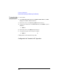
Configuration for Terminal or PC Operation 289
Equivalent Front-Panel Control Characters 289
Disks 292
Initializing a Disk 292
Retrieving Data from a Disk
293
Exiting a Program 295
11
Contents
HP-IB Control Annunciators 296
Memory Cards 297
SRAM Memory Cards 299
Memory Card Storage Space 300
Initializing a Memory Card 301
To initialize an SRAM card using IBASIC 301
To initialize an SRAM card using RAM_MNG 302
Retrieving Data from a Memory Card 302
Parameters 305
Pass/Fail Limits (specifications) 306
Pausing or Stopping a TEST 308
Printing 309
Supported Printers 310
Printer Connection 310
HP-IB Connection 310
Serial Connection 310
Parallel Connection 312
Configuring the Test Set for Printing 313
To Setup Printer Using Any HP 8920B Or HP 8920A FW Above Rev A.14.00
To print test results: 314
To send Escape Sequences to the printer 315
To print TESTS screens: 317
To Setup Printer Using HP 8920A FW Below Rev A.14.00 318
To print test results 319
To send Escape Sequences to the printer 320
To print TESTS screens 322
12
314
Contents
Procedures 323
Saving a Procedure 324
Loading a Procedure 326
Loading a Software Upgrade, FW below rev A.12.04 only
Deleting a Procedure 328
Securing a Procedure 329
326
RAM Disk 331
Initializing RAM Disks 331
To initialize RAM disk Volume 0: 332
To initialize RAM volumes 1, 2, or 3: 333
Saving Tests Results 334
Serial Port 335
Operating Considerations
335
Test Execution Conditions 338
Output Results To: (Output Destination) 338
Output Results For: (Output Results) 338
Output Heading 339
If Unit-Under-Test Fails (If UUT Fails) 339
Test Procedure Run Mode (Run Mode) 339
Autostart Test Procedure on Power-Up 339
USER Keys 340
9 Problem Solving
Data-Collection Function Does Not Work 345
13
Contents
Memory Space Problems 347
Printing Problems 348
Test Results are Unexpected 350
Test Set Doesn’t Power Up 351
Error Messages 352
Error Message Reference
Glossary 365
14
353
1
Getting Started with FW
Above Rev. A.14.00
Getting Started with FW Above Rev.
A.14.00
15
Getting Started with FW Above Rev. A.14.00
What You Will Test
What You Will Test
NOTE:
The firmware revision A.14.00 in the HP 8920A,D had several enhancements,
which are standard in the HP 8920B. This chapter applies to users with the
following Test Sets:
•
HP 8920A, HP 8921A, HP 8920D, and HP 8921D Test Sets with
firmware revision above A.14.00
•
All HP 8920B Test Sets.
The Test Set’s firmware revision is displayed on the top right corner
of the configuration screen.
•
Press SHIFT CONFIG to display the configuration screen and read the
firmware revision.
If you have an HP 8920A, HP 8921A, HP 8920D, or HP 8921D Test
Set with firmware revision below A.14.00, refer to Chapter 2,
"Getting Started with FW Below Rev. A.14.00," on page 31. Contact
Hewlett-Packard at 1-800-922-8920 for details on upgrading your
firmware if desired.
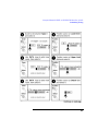
Getting Started will quickly acquaint you with the operation of the test
system and the HP 11807A,E Option 009 Software. You will setup and
run the following:
1. The call processing origination test
2. The transmitter frequency error test
3. The call processing release test
These three tests will establish that the software has been loaded and
verify that the mobile radio is functional.
16
Getting Started with FW Above Rev. A.14.00
What You Will Test
The Test Set or Test System is Defined As:
•
HP 8920B, Option 500, Dual-Mode Cellular Mobile Test System
•
HP 8921A, Option 500, Dual-Mode Cellular Test System
•
HP 8920D, Dual-Mode Cellular Mobile Test System
•
HP 8921D, Dual-Mode Cell Site Test System
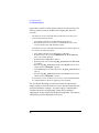
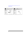
Equipment Needed to Get Started
You will need the following in order to complete the testing in Getting
Started:
•
•
•
•
•
•
•
•
HP 11807A,E Option 009 Software
You will need one of the following:
• HP 8920B, Option 500, Dual-Mode Cellular Mobile Test System
• HP 8921A, Option 500, Dual-Mode Cellular Test System
• HP 8920D, Dual-Mode Cellular Mobile Test System
• HP 8921D, Dual-Mode Cell Site Test System
A mobile unit
A power supply with appropriate connections
Knowledge of the mobile unit’s control channel
A BNC(f) to Type N(m) adapter
A BNC(m) to BNC(m) 4 foot cable for transmitter output to test system RF
IN/OUT connection
A BNC(f) to TNC(m) or BNC(f) to mini-UHF(m) adapter for connection to
the mobile’s antenna
17
Getting Started with FW Above Rev. A.14.00
What You Will Test
This page intentionally left blank.
18
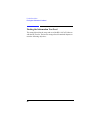
Getting Started with FW Above Rev. A.14.00
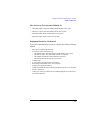
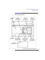
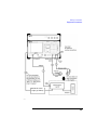
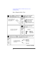
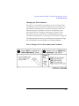
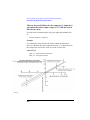
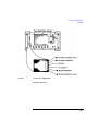
Test System Overview
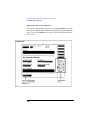
Test System Overview
19
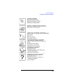
Getting Started with FW Above Rev. A.14.00
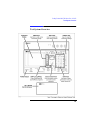
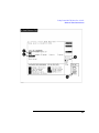
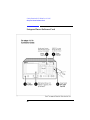
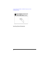
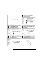
Setup and Insert Software Card
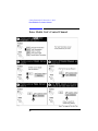
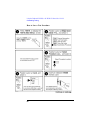
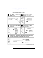
Setup and Insert Software Card
20
Getting Started with FW Above Rev. A.14.00
Setup and Insert Software Card
21
Getting Started with FW Above Rev. A.14.00
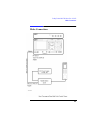
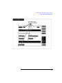
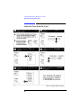
Select the Tests from the Card
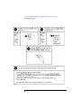
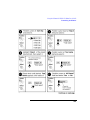
Select the Tests from the Card
22
Getting Started with FW Above Rev. A.14.00
Select the Tests from the Card
23
Getting Started with FW Above Rev. A.14.00
Select the Tests from the Card
This page intentionally left blank.
24
Getting Started with FW Above Rev. A.14.00
Make Connections
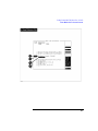
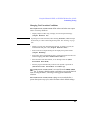
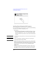
Make Connections
25
Getting Started with FW Above Rev. A.14.00
Enter Mobile Unit’s Control Channel
Enter Mobile Unit’s Control Channel
26
Getting Started with FW Above Rev. A.14.00
Enter Mobile Unit’s Control Channel
27
Getting Started with FW Above Rev. A.14.00
Run the Tests
Run the Tests
28
Getting Started with FW Above Rev. A.14.00
Run the Tests
29
Getting Started with FW Above Rev. A.14.00
Run the Tests
30
2
Getting Started With FW
Below Rev. A.14.00
Getting Started with FW Below Rev.
A.14.00
31
Getting Started with FW Below Rev. A.14.00
What You Will Test
What You Will Test
NOTE:
The firmware revision A.14.00 in the HP 8920A, HP 8921A, HP 8920D and
HP 8921D had several enhancements, which are standard in the HP 8920B.
This chapter applies to users with:
•
HP 8920A, HP 8921A, HP 8920D, and HP 8921D Test Sets with
firmware revision below A.14.00
The Test Set’s firmware revision is displayed on the top right corner
of the configuration screen.
•
Press SHIFT CONFIG to display the configuration screen and read the
firmware revision.
If you have an HP 8920B or an HP 8920A, HP 8921A, HP 8920D, or
HP 8921D with firmware revision above A.14.00, refer to chapter 1,
"Getting Started with FW Above Rev. A.14.00," on page 15. Contact
Hewlett-Packard at 1-800-922-8920 for details on upgrading your
firmware if desired.
Getting Started will quickly acquaint you with the operation of the test
system and the HP 11807A,E Option 009 Software. You will setup and
run the following:
1. The call processing origination test
2. The transmitter frequency error test
3. The call processing release test
These three tests will establish that the software has been loaded and
verify that the mobile radio is functional.
32
Getting Started with FW Below Rev. A.14.00
What You Will Test
The Test Set or System is Defined As:
•
HP 8920B, Option 500, Dual-Mode Cellular Mobile Test System
•
HP 8921A, Option 500, Dual-Mode Cellular Test System
•
HP 8920D, Dual-Mode Cellular Mobile Test System
•
HP 8921D, Dual-Mode Cell Site Test System
Equipment Needed to Get Started
You will need the following in order to complete the testing in Getting
Started:
•
•
•
•
•
•
•
•
HP 11807A,E Option 009 Software
You will need one of the following:
• HP 8920B, Option 500, Dual-Mode Cellular Mobile Test System
• HP 8921A, Option 500, Dual-Mode Cellular Test System
• HP 8920D, Dual-Mode Cellular Mobile Test System
• HP 8921D, Dual-Mode Cell Site Test System
A mobile unit
A power supply with appropriate connections
Knowledge of the mobile unit’s control channel
A BNC(f) to Type N(m) adapter
A BNC(m) to BNC(m) 4 foot cable for transmitter output to test system RF
IN/OUT connection
A BNC(f) to TNC(m) or BNC(f) to mini-UHF(m) adapter for connection to
the mobile’s antenna
33
Getting Started with FW Below Rev. A.14.00
What You Will Test
This page intentionally left blank.
34
Getting Started with FW Below Rev. A.14.00
Test System Overview
Test System Overview
35
Getting Started with FW Below Rev. A.14.00
Setup and Insert Software Card
Setup and Insert Software Card
36
Getting Started with FW Below Rev. A.14.00
Setup and Insert Software Card
37
Getting Started with FW Below Rev. A.14.00
Select the Tests from the Card
Select the Tests from the Card
38
Getting Started with FW Below Rev. A.14.00
Select the Tests from the Card
39
Getting Started with FW Below Rev. A.14.00
Select the Tests from the Card
This page intentionally left blank
40
Getting Started with FW Below Rev. A.14.00
Make Connections
Make Connections
41
Getting Started with FW Below Rev. A.14.00
Enter Mobile Unit’s Control Channel
Enter Mobile Unit’s Control Channel
42
Getting Started with FW Below Rev. A.14.00
Enter Mobile Unit’s Control Channel
43
Getting Started with FW Below Rev. A.14.00
Run the Tests
Run the Tests
44
Getting Started with FW Below Rev. A.14.00
Run the Tests
45
Getting Started with FW Below Rev. A.14.00
Run the Tests
46
Bleeding Tab-First Position
Position bottom line of text
3
Product Description
Product Description
47
Product Description
HP 11807A,E Software
HP 11807A,E Software
The HP 11807A,E Option 009 Software when used with the test system
provides parametric test capability for 800 MHz Dual-Mode Mobile
Stations.
HP 11807A,E Option 009 software can be used for the installation,
maintenance, and/or repair of Dual Mode (NADC) Phones. For a
complete list of Tests and their descriptions, see "Test Descriptions" on
page 133.
Items Included in the HP 11807A,E Option 009 Software
•
•
•
•
HP 11807A Option 009 Test Software (part number 11807-10009) or HP
11807E Option 009 Test Software (part number 11807-10028).
SRAM memory card (uninitialized), for saving your own test procedures
and results.
•
For HP 11807A, 32 Kbyte SRAM (part number HP 85700A).
•
For HP 11807E, 64 Kbyte SRAM (part number HP 83230A).
HP 11807A,E Option 009 Software Reference Guide
(part number 11807-90124).
HP software product license agreement.
Software Function
•
•
•
Automation of measurements
Parametric verification for 800 MHz Dual-Mode Phones
In-depth call processing, including call setup and handoffs
Software Features
The following features simplify testing:
•
48
Test results and pass/fail indications are displayed on the Test System CRT,
and can be printed, or collected in a disk drive, memory card, PC, or HP
Product Description
HP 11807A,E Software
Palmtop computer.
•
Test results can be printed.
•
The software allows the operator to change test order, pass/fail limits,
testing conditions and equipment configurations.
•
RF path losses can be determined and corrected.
Equipment Needed
•
HP Test Set consisting of one of the following:
•
•
•
•
HP 8920B, Option 500, Dual-Mode Cellular Mobile Test System
HP 8921A, Option 500, Dual-Mode Cellular Test System
HP 8920D, Dual-Mode Cellular Mobile Test System
HP 8921D, Dual-Mode Cell Site Test System
The Test Set offers TDMA Dual-Mode Mobile test capability plus the
analog mobile test capability offered by the HP 8920A,B or HP 8921A.
•
•
•
•
The HP 8920B Option 500 consists of:
• HP 8920B RF Communications Test Set
• The HP 83201B, Option 003, TDMA Dual-Mode Cellular Adapter
The HP 8921A Option 500 consists of:
• HP 8921A Cell Site Test Set
• The HP 83204A, Option 001, TDMA Dual-Mode Cellular Adapter
The HP 8920D consists of:
• HP 8920A RF Communications Test Set with Options 003, 004,
005, 013, and 050.
• HP 83201A Dual-Mode Cellular Adapter.
The HP 8921D consists of:
• HP 8921A Cell Site Test Set
• HP 83201A Dual-Mode Cellular Adapter
In addition to the above hardware configurations, this software can be
used with Test Sets that have Options 006, 007, or 008.
The internal firmware of the HP 8920A and HP 8921A must be equal
to or greater than a specific revision for the software to work correctly.
The software works correctly in all HP 8920B firmware revisions. In
addition, the internal firmware of the HP 83201 must be equal to or
49
Product Description
HP 11807A,E Software
greater than a specific revision for the software to work correctly. The
software works correctly in all HP 83204A Option 001 firmware
revisions.
•
The firmware revision of the HP 8920A or HP 8921A Test Set can be
viewed in the following manner.
•
•
Press SHIFT CONFIG on the HP 8920A,B or HP 8921A.
Read the firmware revision on the I/O CONFIGURE screen. This
revision number must be A.10.04 or greater.
The firmware revision of the HP 83201A Dual Mode Cellular Adapter can
be viewed in the following manner.
•
•
•
•
•
•
•
Press SHIFT CONFIG on the HP 8920A or HP 8921A.
Rotate the knob until you locate SERVICE under To Screen and
select it by pushing the knob.
Rotate the knob to Latch and select it.
Rotate the knob until you find rx_dsp_revision under Choices,
and select it.
Read the rx_dsp_revision number under Value. This revision
number must be 19930909 or greater.
Select Latch again and rotate the knob to tx_dsp_revision and
select it.
Read the tx_dsp_revision number under Value. This revision
number must be 19930909 or greater.
If any of these revision numbers are not correct, contact Hewlett-Packard
at 1-800-922-8920 for details on upgrading your instrument.
The Test Set has the ability to make tests at normal, high, and low
supply voltages to the radio under test. If you want to perform the tests
associated with these voltages a dc power supply is required that is
variable from the low to high supply voltage and is capable of
supplying the current required by the phone being tested. The software
will prompt you when adjustment is necessary.
50
Product Description
HP 11807A,E Software
If you desire to use an HP-IB power supply that is controlled by the
software over HP-IB, a Hewlett-Packard dc power supply with
appropriate voltage and current capabilities from the following series
must be used:
•
•
•
•
NOTE:
HP 664xA
HP 665xA
HP 667xA
HP 668xA
HP 662xA and HP 663xA series dc power supplies are not supported.
•
Connection arrangements, see chapter 4, "Making Connections," on page
55 for more detail
•
Optional Accessories
•
•
•
SRAM (Static Random Access Memory) Card(s) for storing test setups
and test results (see Memory Cards in chapter 5 for part numbers).
Printer and cables to document results.
PC, disk drive, or HP Palmtop computer to store data.
51
Product Description
Finding the Information You Need
Finding the Information You Need
This manual describes the setup and use of the HP 11807A,E Software
with the HP Test Set. The book is arranged in self contained chapters to
meet the following objectives:
52
Product Description
Finding the Information You Need
4
5 and 6
7
8
9
53
Product Description
Additional Services Available
Additional Services Available
Consult the HP 8920A Users Guide or call the HP 8920D/HP 8921D Hotline
1-800-922-8920 (In USA and Canada only) and give your software model
number.
Contact your local HP Sales Representative for information about the
Software Upgrade Service and the Start Up Assistance Training
Course.
54
4
Making Connections
Making Connections
55
Making Connections
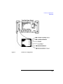
Equipment Connections
Equipment Connections
Mobile Unit to Test System Connection
Numerous cables and connectors are required to interface the radio to
the test system. Table 1 on page 57 lists the necessary equipment for
connection.
Damage to Equipment
CAUTION:
The Test Set can be damaged by transient RF power, continuous RF power,
high voltage, and electrostatic discharge from cables and other sources.
See "Printing," in chapter 8, on page 309, for printer connections to
the serial port.
56
Making Connections
Equipment Connections
Audio Connections
Audio connections are only used for the following tests:
TEST_05 - TXA Modulation Deviation Limiting
TEST_06 - TXA Audio Frequency Response
TEST_07 - TXA Audio Distortion
TEST_09 - TXA Hum and Noise
TEST_12 - TXA Compressor Response
TEST_14 - RXA Expandor
TEST_15 - RXA Audio Frequency Response
TEST_16 - RXA Audio Distortion
TEST_17 - RXA Hum and Noise
TEST_18 - RXA SINAD
TEST_23 - TXA Quick General
TEST_24 - RXA Quick General
The method of the audio connections is dependent on the mobile unit
being tested. Consult the mobile manufacturer for the correct method
of audio connection. Some manufacturers provide a method for audio
signal breakout while others require that the audio lines to the handset
be tapped or an acoustic coupler be used on the handset.
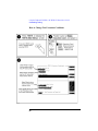
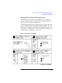
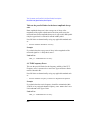
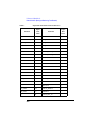
Cables and Connectors
Table 1
Reference #
Cables and Connectors
Description
Purpose
Quantity
Needed
Part Number
1
BNC(f) to Type
N(m) adapter
Adapt BNC cable to RF
IN/OUT
1
HP 1250-0780
2
BNC(f) to TNC(m)
adapter or BND(f) to
mini-UHF(m)
adapter depending on
mobile unit
Adapt BNC cable to
antenna out
1
HP 1250-2441 for
TNC only or
Tessco part #74720
3
BNC(m) to BNC(m)
cable, 4 ft.
Antenna and audio
3
HP 10503A
57
Making Connections
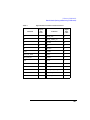
Equipment Connections
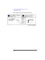
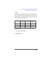
Table 1
Reference #
Cables and Connectors
Description
Purpose
Quantity
Needed
Part Number
4
BNC(m) to
Banana(f) adapter
AUDIO IN, HI and LO
2
HP 1250-2164
5
Banana(m) to
BNC(f) adapter
Test system AUDIO IN
3
HP 1251-2277
6
HP-IB Interface
cable 1 meter
Test system HP-IB to
power supply HP-IB
1
HP 10833A
58
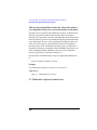
Making Connections
Equipment Connections
HP-IB DC Power
Supply (if desired)
59
Making Connections
Equipment Connections
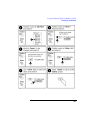
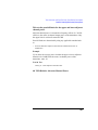
Printer Cables
Table 2
Hewlett-Packard Printer Cables
Description
HP Model
Number or
Part Number
Purpose
Quantity
HP-IB (IEEE 488) Cable, 1
meter (3.3 feet)
Test Set to HP-IB Printer
1
10833A
HP-IB (IEEE 488) Cable, 2
meter (6.6 feet)
Test Set to HP-IB Printer
1
10833B
Parallel (IEEE 1284) Printer
Cable, 2 meter (6.6 feet)
Test Set to Parallel
(Centronics) Printer
1
C2950A
Parallel (IEEE 1284) Printer
Cable, 3 meter (9.9 feet)
Test Set to Parallel
(Centronics) Printer
1
C2951A
Serial Printer Cable, 4-pin
RJ-11 (male) to 9-pin DB-9
(female), 2 meter (6.6 feet)
Test Set to Serial Printer
(with 9-pin connector)
1
08921-61038
Serial Printer Cable, 4-pin
RJ-11 (male) to 25-pin DB25 (male), 3 meter (9.9 feet)
Test Set to Serial Printer
(with 25-pin connector)
1
08921-61039
60
Making Connections
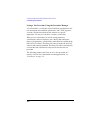
Calibrating Cable Loss
Calibrating Cable Loss
Inaccuracies can occur in your RF measurements due to cable losses
and impedance mismatches. These inaccuracies can be calibrated out
by running TEST_40 - TXD Calibrate RF Power (see "Test
Descriptions" on page 133) which produces calibration factors at
different power levels and frequencies. Other RF tests will use these
measured calibration factors when running tests. The test software will
run with its own default calibration factors until you run TEST_40.
61
Making Connections
Calibrating Cable Loss
62
Using the Software HP 8920B,
or HP 8920A FW Above Rev.
A.14.00
5
Using the Software HP 8920B, or HP
8920A FW Above Rev. A.14.00
63
Using the Software HP 8920B, or HP 8920A FW Above Rev. A.14.00
NOTE:
The firmware revision A.14.00 in the HP 8920A,D had several enhancements,
which are standard in the HP 8920B. This chapter applies to users with:
•
HP 8920A, HP 8921A, HP 8920D, and HP 8921D Test Sets with
firmware revision above A.14.00
•
All HP 8920B Test Sets.
The Test Set’s firmware revision is displayed on the top right corner
of the configuration screen.
•
Press SHIFT CONFIG to display the configuration screen and read the
firmware revision.
If you have an HP 8920A Test Set with firmware revision below
A.14.00, refer to chapter 6, "Using the Software HP 8920A FW
Below Rev A.14.00," on page 97. Contact Hewlett-Packard at
1-800-922-8920 for details on upgrading your firmware if desired.
64
Using the Software HP 8920B, or HP 8920A FW Above Rev. A.14.00
The software can be run on the factory default settings or customized to
your individual needs and specific requirements. This chapter provides
detailed information on how to load, run, and customize the software.
The Test Set has two methods of accessing on-line help. In each of the
screens in the test environment, k4 (Help) accesses specific information about how to set up/use the current screen. SHIFT HELP accesses
the master help file, with an alphabetical listing of help topics.
65
Using the Software HP 8920B, or HP 8920A FW Above Rev. A.14.00
Testing Overview
Testing Overview
Pressing TESTS will display what is called the TESTS (Main Menu)
screen. To begin testing, you must first load the software and make
connections. From this screen you have the option to:
Begin running tests:
•
The factory default settings are acceptable for your application or
•
The software has already been customized and saved to a memory card.
Customize the software:
•
Decide which tests you desire to run (Order of Tests)
•
•
Specify which channels to test (Channel Information)
•
•
•
you may want to test one, some, or all of the channels on your radio.
Change the pass/fail limits for specific measurements (Pass/Fail Limits)
•
•
you may want to run all, some, or just one of the tests.
you may want the pass/fail limits to have tighter or looser specifications
than the default settings.
Change the test environment and conditions (Test Parameters)
•
decide output format.
•
enter specific information about radio equipment and/or environment.
Save any or all of the above customized changes to a memory card (Save/
Delete Procedure)
Set Up Test Set:
•
Print test results or certain screens.
•
Decide when and where test results are displayed (Execution
Conditions/Printer Setup).
66
Using the Software HP 8920B, or HP 8920A FW Above Rev. A.14.00
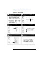
Running Tests Overview
Running Tests Overview
67
Using the Software HP 8920B, or HP 8920A FW Above Rev. A.14.00
Running Tests Overview
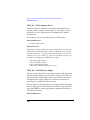
Before Running Tests
•
Select a test procedure from the HP 11807A,E Option 009 software card.
The software is shipped with the following preprogrammed test procedures
on the program card:
MANUAL contains TEST_25 - CP Manual Flow Chart which allows real
time control of the mobile unit’s channel, SAT and power.
CALL_PR contains call processing tests.
FUNCTNL contains RF and call processing (no audio) tests.
PARAMTR contains parametric tests including RF, audio and call
processing.
REGISTR contains one test, TEST_01 - CP Registration.
STARTED contains three tests used in chapter 1, Getting Started.
•
68
Before you begin testing, you should have made the appropriate hardware
connections. See chapter 1, "Getting Started with FW Above Rev. A.14.00,"
on page 15 or chapter 2, "Getting Started with FW Below Rev. A.14.00,"
on page 31. See chapter 4, "Making Connections," on page 55 if you have
not done so already.
Using the Software HP 8920B, or HP 8920A FW Above Rev. A.14.00
Running Tests Overview
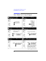
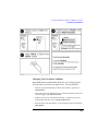
Selecting a Test Procedure
To load the software, you must first select the location to load from (in
this case, it will be Card) and a procedure filename. Your card comes
pre-programmed with at least one procedure. The actual software
program does not get loaded into the Test Set’s memory until k1 (Run
Test) is selected. It will take approximately 15 seconds to load the
software in an HP 8920B, and approximately two minutes in an HP
8920A,D.
The software memory card can be removed after the program is loaded
into the Test Set’s memory. The program will remain in memory after a
power-down/power-up cycle, unless it is manually deleted or a new
program is loaded.
When tests begin to run, they are executed in the order in which they
were entered into the Test Procedure.
Pressing CANCEL will pause the current test (press k2 to continue the
test.)
69
Using the Software HP 8920B, or HP 8920A FW Above Rev. A.14.00
Running Tests Overview
Selecting A Test Procedure
70
Using the Software HP 8920B, or HP 8920A FW Above Rev. A.14.00
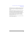
Customizing Testing
Customizing Testing
Because of the diversity of individual testing needs, the software has
been designed so that changes may be easily made from the Test Set’s
front panel. You may store these changes on a memory card so that you
may skip these steps in the future. See "Saving a Test Procedure" on
page 89.
Because your needs change, the software allows changes to its default
settings whenever you need to make them. For example, tests may be
inserted or deleted, and later after running the tests you can change the
pass/fail limits or decide to test different channels.
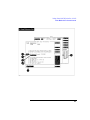
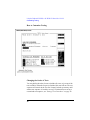
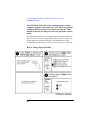
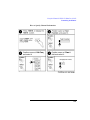
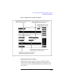
Most testing customization is accomplished through the customization
screens. These customization screens are accessed from the main
TESTS (Main Menu) screen as shown in the following figure.
Customizing procedures is explained later in this chapter.
NOTE:
External Devices, Printer Setup, and IBASIC will not be explained in this customizing
section.
•
External Devices and Printer Setup are used when setting up printers and external
disk drives which is explained in "Disks" on page 292 and "Printing" on page 309.
•
IBASIC is used when writing your own programs and is not explained in this
manual. If you need to write your own IBASIC programs you may acquire the
following manuals:
•
•
HP 8920A,D
•
HP Instrument Basic User’s Handbook HP part number
E2083-90000.
•
HP 8920 Programming Manual HP part number 08920-90204.
HP 8920B
•
HP Instrument Basic User’s Handbook Version 2.0 HP part number
E2083-90005.
•
HP 8920 Programming Manual HP part number 08920-90204.
71
Using the Software HP 8920B, or HP 8920A FW Above Rev. A.14.00
Customizing Testing
How to Customize Testing
Changing the Order of Tests
You may define the order of tests to include all, some, or just one of the
tests available. When the first test is finished, the next will run. The test
sequence will remain in the Test Set’s battery backed-up memory until
another test sequence is loaded or set up. For information on saving a
customized test sequence, see "Saving a Test Procedure" on page 89.
72
Using the Software HP 8920B, or HP 8920A FW Above Rev. A.14.00
Customizing Testing
Defining the order of tests is accomplished by inserting or deleting tests
from the list of tests that come with the software package. See "Test
Descriptions" on page 133, for descriptions of tests included in this
package.
The All Chans? field allows the user to decide to run the test on all
channels entered in the Channel Information table, or just the
channels which are selected as Prime in the Channel Information
screen. This feature allows the user the flexibility to use channels that
are selected as Prime in all the tests in the sequence, and those
indicated as non-prime in a subset of tests (those tests with a Yes
response in All Chans). For more information, see "Specifying
Channel Information" on page 76.
The following describes how to create a new test sequence and enter a
response to the All Chans? field.
73
Using the Software HP 8920B, or HP 8920A FW Above Rev. A.14.00
Customizing Testing
How to Change the Order of Tests
74
Using the Software HP 8920B, or HP 8920A FW Above Rev. A.14.00
Customizing Testing
75
Using the Software HP 8920B, or HP 8920A FW Above Rev. A.14.00
Customizing Testing
Specifying Channel Information
76
Using the Software HP 8920B, or HP 8920A FW Above Rev. A.14.00
Customizing Testing
For each channel that you wish to specify, you must enter the
following information into the Channel Information screen:
•
•
•
•
Cell Channel
• Enter the cellular channel number.
• For narrow channels (NAMPS only), specify lower, middle, or upper
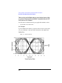
channel by appending an “L”, “M”, or “U” after the channel number.
Example: For narrow lower channel 156 enter 156L in the channel
information screen.
Options
• For the last channel that you want tested in the Channel
Information table, select Options and using the characters in the
Choices menu enter END. This will speed up the testing time (so the
software will not scan through the entries that are blank in the Channel
Information screen).
Test? (yes/no) specifies whether you want to test the UUT at this channel.
If set to “No” then the UUT will not be tested at that channel, but you may
retain the channel information in the table for later use. If set to “Yes” then
the channel will be used as defined by settings of Prime? and All
Chans? fields.
Prime? (yes/no) specifies which channels are “prime”. Select “Yes” if
you want to test the UUT at this channel on all the tests in the procedure.
Select No if you want to test the UUT at this channel on just a subset of
tests, which are designated by selecting Yes in the All Chans field of
the Order of Tests screen. See All Chans? in Changing the Order
of Tests for more information.
77
Using the Software HP 8920B, or HP 8920A FW Above Rev. A.14.00
Customizing Testing
For information on saving the channel information table, see "Saving a
Test Procedure" on page 89.
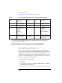
The All Chans field in the Order of Tests screen interacts closely
with the Prime? field on the Channel Information screen. When the
software runs, it begins by retrieving the first channel entered into the
Channel Information screen. It then checks the response in the Test?
field to determine if the UUT should be tested at that channel at this
time. If there is a No response in the Test? field, the software will go
to the next channel in the table. If there is a Yes response in the Test?
field, the software will check if the channel is Prime.
A Yes response in the Prime? field indicates to test the UUT at that
channel on the entire sequence of tests in the procedure. A No response
in the Prime? field indicates to test the UUT at that channel on a
subset of tests in the procedure. The subset of tests is determined by a
Yes response in the All Chans? field. Therefore, tests with a No
response in the All Chans? field will be run on prime channels only.
78
Using the Software HP 8920B, or HP 8920A FW Above Rev. A.14.00
Customizing Testing
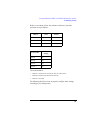
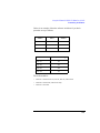
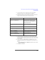
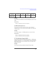
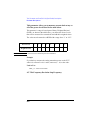
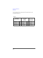
Below is an example of how the software would run if you had a
procedure set up as follows:
Chan #
Test?
Prime?
Chan 01
Yes
Yes
Chan 02
Yes
No
Chan 03
No
No
Test Number
All Chan?
Setting
Test 01
No
Test 02
Yes
Test 03
Yes
Test 04
No
The result would be:
•
Chan 01 is used in Test 01, Test 02, Test 03, and Test 04.
•
Chan 02 is used in Test 02, and Test 03 only.
•
Chan 03 is not used.
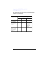
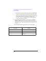
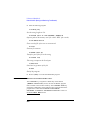
The following table shows how to properly configure these settings
according to your testing needs.
79
Using the Software HP 8920B, or HP 8920A FW Above Rev. A.14.00
Customizing Testing
Necessary Field Settings
Testing Need
Test?
Prime?
All Chan?
Test channel
on all tests in
sequence
Yes
Yes
Don’t Care
Test channel
on a subset of
tests in
sequence
Yes
No
Yes on tests
you want
included in
the testing
subset
Do not test
this channel
now, but retain
information
for later use
No
Don’t Care
Don’t Care
80
Using the Software HP 8920B, or HP 8920A FW Above Rev. A.14.00
Customizing Testing
How to Specify Channel Information
81
Using the Software HP 8920B, or HP 8920A FW Above Rev. A.14.00
Customizing Testing
82
Using the Software HP 8920B, or HP 8920A FW Above Rev. A.14.00
Customizing Testing
Changing Pass/Fail Limits
83
Using the Software HP 8920B, or HP 8920A FW Above Rev. A.14.00
Customizing Testing
Pass/Fail limits define the values a measurement’s result is
compared against to determine if the UUT meets its specified
standards. Default values are set in the test software. These
default values may be changed to suit your particular requirements.
The following describes how to change the pass/fail (upper and lower)
limits. See "Pass/Fail Limit (Specification) Descriptions" on page 224.
for descriptions of each pass/fail limit. For information on saving
customized pass/fail limits, see "Saving a Test Procedure" on page 89.
How to Change Pass/Fail Limits
84
Using the Software HP 8920B, or HP 8920A FW Above Rev. A.14.00
Customizing Testing
85
Using the Software HP 8920B, or HP 8920A FW Above Rev. A.14.00
Customizing Testing
86
Using the Software HP 8920B, or HP 8920A FW Above Rev. A.14.00
Customizing Testing
Changing the Test Parameters
The software uses parameters to optimize the test environment and
conditions for your testing situation. Many of the test parameters are
determined by examining your test needs. The software comes with
default settings for test parameters. Review the defaults for your
particular needs. See "Parameter Descriptions" on page 182 for
descriptions of each test parameter. For information on saving
customized test parameters, see "Saving a Test Procedure" on page 89.
The following describes how you can change test parameters through
the Test Parameter screen to optimize your testing conditions.
How to Change the Test Environment and Conditions
87
Using the Software HP 8920B, or HP 8920A FW Above Rev. A.14.00
Customizing Testing
88
Using the Software HP 8920B, or HP 8920A FW Above Rev. A.14.00
Customizing Testing
Saving a Test Procedure
A Test Procedure is a collection of channel information, test
parameters, testing order, and pass/fail limits saved in a file that
customizes the test software to a specific application. You may save the
file to a memory card or disk.
When you save a procedure you will be saving channel information,
test parameters, pass/fail limits, and testing order, plus a library that
contains the names of all test parameters, pass/fail limits, and tests that
are resident in the software. The library file comes from the software
and cannot be modified. The library file will be automatically saved on
the card or disk that is being used to store the new test procedure.
The following example shows how to save a new procedure to a
memory card. For more information concerning procedures, see
"Procedures" on page 323.
89
Using the Software HP 8920B, or HP 8920A FW Above Rev. A.14.00
Customizing Testing
How to Save a Test Procedure
90
Using the Software HP 8920B, or HP 8920A FW Above Rev. A.14.00
Customizing Testing
91
Using the Software HP 8920B, or HP 8920A FW Above Rev. A.14.00
Customizing Testing
92
Using the Software HP 8920B, or HP 8920A FW Above Rev. A.14.00
Customizing Testing
Changing Test Execution Conditions
Test Execution Conditions define where and when test output
occurs. You may decide to:
•
NOTE:
Display output on CRT only, or display on CRT and print hardcopy
(Output Results To).
If printing test results is desired, after selecting Printer, additional steps
are necessary to connect and configure the printer. See "Printing" on page
309.
•
Display (or print) only measurements that fail, or display (or print) all
measurements that pass or fail (Output Results For).
•
Enter a title for an output heading for the displayed or printed results
(Output Heading).
•
Stop testing when a measurement fails or continue through all of the tests
without stopping (If Unit-Under-Test-Fails).
•
Pause between each measurement, or run through entire test (Test
Procedure Run Mode).
•
Start the program automatically when the Test System is powered on.
(Autostart Test Procedure on Power-up).
Test Execution Conditions is accessed from the SETUP TEST
SET: list. To change a default setting, position the cursor to the desired
field. Pressing the knob (”selecting”) will toggle the underlined
selection.
Test Execution Conditions settings are not retained after a
power-down/power-up cycle, and will return to their default settings.
93
Using the Software HP 8920B, or HP 8920A FW Above Rev. A.14.00
Customizing Testing
How to Change Test Execution Conditions
94
Using the Software HP 8920B, or HP 8920A FW Above Rev. A.14.00
Customizing Testing
Printing and Saving Test Results
Printing and saving test results are features of the software which
require additional equipment and configuration. See "Printing" on
page 309 for detailed descriptions and instructions for these features.
95
Using the Software HP 8920B, or HP 8920A FW Above Rev. A.14.00
Customizing Testing
96
6
Using the Software HP 8920A
FW Below Re. A.14.00
Using the Software HP 8920A FW Below
Rev A.14.00
97
Using the Software HP 8920A FW Below Rev A.14.00
NOTE:
The firmware revision A.14.00 in the HP 8920A,D had several enhancements,
which are standard in the HP 8920B. This chapter applies to users with:
•
HP 8920A, HP 8921A, HP 8920D, and HP 8921D Test Sets with
firmware revision below A.14.00
The Test Set’s firmware revision is displayed on the top right corner
of the configuration screen.
•
Press SHIFT CONFIG to display the configuration screen and read the
firmware revision.
If you have an HP 8920B or an HP 8920A, HP 8921A, HP 8920D, or
HP 8921D with firmware revision above A.14.00, refer to Chapter 5,
"Using the Software HP 8920B, or HP 8920A FW Above Rev.
A.14.00," on page 63. Contact Hewlett-Packard at 1-800-922-8920
for details on upgrading your firmware if desired.
98
Using the Software HP 8920A FW Below Rev A.14.00
The HP 11807A,E software can be run on the factory default settings or
customized to your individual needs and the specific requirements.
This chapter provides detailed information on how to load, run, and
customize the software.
99
Using the Software HP 8920A FW Below Rev A.14.00
Running Tests Overview
Running Tests Overview
(Chapter 6)
100
Using the Software HP 8920A FW Below Rev A.14.00
Running Tests Overview
Before Running Tests
•
Select a test procedure from the HP 11807A,E Option 009 software card.
The software is shipped with the following preprogrammed test procedures
on the program card
MANUAL contains TEST_25 - CP Manual Flow Chart which allows real
time control of the mobile unit’s channel, SAT and power.
CALL_PR contains call processing tests.
FUNCTNL contains RF and call processing (no audio) tests.
PARAMTR contains parametric tests including RF, audio and call
processing.
REGISTR contains one test, TEST_01 - CP Registration.
STARTED contains three tests used in chapter 1, Getting Started.
•
Before you begin testing, you should have made the appropriate hardware
connections. See chapter 4, "Making Connections," on page 55 if you have
not done so already.
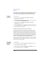
Running Tests
•
When tests begin to run, they are executed in the order in which they were
entered into the Test Procedure.
•
Pressing CANCEL will pause the current test (press Continue to
continue the test).
•
When the Run Test softkey is pressed, the Test Set will check to see if
the program is already resident in RAM memory. If it is not, it will be
loaded from the memory card, a process which takes about two minutes.
Loading a Software Upgrade, FW below rev A.12.04 only
If you have purchased a software upgrade from the factory and are loading it for the first time, you must clear the old revision software from the
Test Set memory before running the new revision software. If you do not,
the new revision will not be loaded, and the old revision will be used. This
is for FW below revision A.12.04 only. For firmware revision A.12.04 and
above, the Test Set will check for differences in the code, and automatically
load the most updated version.
The easiest way to clear the old revision software is to load a different software program. The LIST_OPTS program that is stored in internal ROM
101
Using the Software HP 8920A FW Below Rev A.14.00
Running Tests Overview
can be used for this purpose.
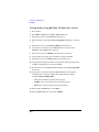
To Load the LIST_OPTS Program:
1. Press TESTS.
2. Position the cursor to Select Procedure Location and select it.
3. From the Choices menu, select ROM.
4. Position the cursor to Select Procedure Filename and select it.
5. From the Choices menu, select LIST_OPS.
6. Press k1 (Run Test).
The new revision software can now be loaded.
102
Using the Software HP 8920A FW Below Rev A.14.00
Selecting a Test Procedure
Selecting a Test Procedure
103
Using the Software HP 8920A FW Below Rev A.14.00
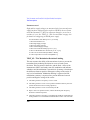
Customizing the Software
Customizing the Software
The HP 11807A,E software may need some customizing before it
performs in a way that is specific to your testing needs. Because of the
diversity of individual testing needs, the software has been designed so
that changes may be easily made from the Test Set’s front panel. You
may store these changes on an SRAM card so that you may skip these
steps in the future. See "Saving a Test Procedure Using the Procedure
Manager" on page 122.
You may customize your software at any time. Because your needs
change, the software allows changes to its default settings when you
need to make them and in any order that you choose. For example, tests
may be inserted or deleted, and later after running the tests you can
change the pass/fail limits or decide to test different channels.
Most testing customization is accomplished through the Test Set’s Test
Function screens. These Test Function screens are accessed from the
main TESTS screen as shown in the following figure. All Test
Functions are explained in this chapter by function.
104
Using the Software HP 8920A FW Below Rev A.14.00
Customizing the Software
•
Decide which tests you need to run edit sequence (Edit Seqn).
•
•
Change the pass/fail limits for specific measurements (edit specifications
(Edit Spec)).
•
•
You may want the pass/fail limits to have tighter or looser
specifications than the default settings.
Change the test environment and conditions (edit parameters (Edit
Parm)).
•
NOTE:
You may want to run all, some, or just one of the tests.
Enter specific information about radio equipment and/or environment.
•
Save any or all of the above customized changes (to an SRAM card)
•
Select options from the TESTS screen.
•
Print test results.
•
Stop after each test, stop on failure or always continue.
•
Display all test results or only those that fail.
Edit Configuration (Edit Cnfg) and IBASIC will not be explained in this
customizing section.
•
Edit Configuration (Edit Cnfg) is used when setting up printers and
external disk drives which is explained in Disks and Printing in chapter 5.
•
IBASIC is used when writing your own programs and is not explained in
this manual. If you need to write your own IBASIC programs you may
acquire the HP 8920/8921 Progammer’s Guide, HP part number
08920-90204.
105
Using the Software HP 8920A FW Below Rev A.14.00
Customizing the Software
Beginning Software Customization
All software customization begins by accessing the TESTS screen first
and then selecting the Test Function which will open the Choices
menu. To access the TESTS screen, press TESTS on the front panel of
the Test Set.
106
Using the Software HP 8920A FW Below Rev A.14.00
Customizing the Software
Changing the Order of Tests (Edit Sequence)
You may define a test sequence to include all, some, or just one of the
tests available. When the first test is finished, the next will run. The test
sequence will remain in the Test System’s battery backed-up memory
until another test sequence is loaded or set up. For information on
saving a customized test sequence, see "How to Save a Test Procedure"
on page 123.
Creation of a test sequence is accomplished by inserting or deleting
tests from the list of tests that come with the HP 11807A,E software
package. See Test Descriptions in chapter 4, for test descriptions.
The All Chans? field allows the user to decide to run the test on all
channels entered in the frequency table, or just the channels which are
selected as Prime in the Edit Freq screen. This feature allows the
user the flexibility to use channels that are selected as Prime in all the
tests in the sequence, and those selected as non-prime in a subset of
tests (those with a Yes response in All Chans). For more information,
see "How to Specify Channel Information" on page 115.
The following describes how to create a new test sequence and enter a
response to All Chans.
107
Using the Software HP 8920A FW Below Rev A.14.00
Customizing the Software
How to Change a Sequence of Tests
108
Using the Software HP 8920A FW Below Rev A.14.00
Customizing the Software
109
Using the Software HP 8920A FW Below Rev A.14.00
Customizing the Software
Specifying Channel Information (Edit Frequency)
For each channel that you wish to specify, you must enter the following
information into the Edit Frequency screen:
•
RX Chan Info
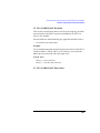
• Enter the channel number of the voice channel to be tested. narrow|
• For narrow channels (NAMPS only), specify lower, middle, or upper
channel by appending an “L”, “M”, or “U” after the channel number.
Example: for narrow lower channel 156 enter 156L in the edit frequency screen
NOTE:
The RX Freq and TX Freq fields are not used for entering cellular channel
frequencies.
NOTE:
Enter a −1 in the RX or TX Frequency fields to have all subsequent
channels ignored when testing is started.
•
•
Test? (yes/no) specifies whether you want to test the UUT at this channel.
If set to “No” then the UUT will not be tested at that channel, but you may
retain the channel information in the table for later use. If set to “Yes” then
the channel will be used as defined by settings of Prime? and All
Chans? fields.
Prime? (yes/no) specifies which channels are “prime”. Select “Yes” if
you want to test the UUT at this channel on all the tests in the procedure.
Select No if you want to test the UUT at this channel on just a subset of
110
Using the Software HP 8920A FW Below Rev A.14.00
Customizing the Software
tests, which are designated by selecting Yes in the All Chans field of
the Edit Seqn screen. See All Chans? in "How to Change a Sequence
of Tests" on page 108 for more information.
For information on saving the frequency table, see "How to Save a Test
Procedure" on page 123.
111
Using the Software HP 8920A FW Below Rev A.14.00
Customizing the Software
The All Chans field in the Edit Seqn screen interacts closely with
the Prime? field on the Edit Freq screen. When the software runs, it
begins by retrieving the first channel entered into the Edit Freq
screen. It then checks the response in the Test? field to determine if
the UUT should be tested at that channel at this time. If there is a No
response in the Test? field, the software will go to the next channel in
the table. If there is a Yes response in the Test? field, the software
will check if the channel is Prime.
A Yes response in the Prime? field indicates to test the UUT at that
channel on the entire sequence of tests in the procedure. A No response
in the Prime? field indicates to test the UUT at that channel on a
subset of tests in the procedure. The subset of tests is determined by a
Yes response in the All Chans? field. Therefore, tests with a No
response in the All Chans? field will be run on prime channels only.
112
Using the Software HP 8920A FW Below Rev A.14.00
Customizing the Software
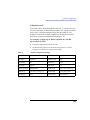
Below is an example of how the software would run if you had a
procedure set up as follows:
Chan #
Test?
Prime?
Chan 01
Yes
Yes
Chan 02
Yes
No
Chan 03
No
No
Test Number
All Chan? Setting
Test 01
No
Test 02
Yes
Test 03
Yes
Test 04
No
The result would be:
•
Chan 01 is used in Test 01, Test 02, Test 03, and Test 04.
•
Chan 02 is used in 02, and Test 03 only.
•
Chan 03 is not used.
113
Using the Software HP 8920A FW Below Rev A.14.00
Customizing the Software
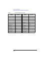
The following table shows how to properly configure these settings
according to your testing needs.
Necessary Field Settings
Testing Need
Test?
Prime?
All Chan?
Test channel on all
tests in sequence
Yes
Yes
Don’t Care
Test channel on a
subset of tests in
sequence
Yes
No
Yes on tests
you want
included in
the testing
subset
Do not test this
channel now, but
retain information
for later use
No
Don’t Care
Don’t Care
114
Using the Software HP 8920A FW Below Rev A.14.00
Customizing the Software
How to Specify Channel Information
115
Using the Software HP 8920A FW Below Rev A.14.00
Customizing the Software
116
Using the Software HP 8920A FW Below Rev A.14.00
Customizing the Software
Changing Pass/Fail Limits (Edit Specifications)
Specifications are values that set pass/fail limits for tests. Default
values are available in the test software. These default values may be
changed to suit your particular requirements.
The following describes how to change the pass/fail (upper and lower)
limits in the HP 8920D/HP 8921D Edit Specification screen. See
Specifications in chapter 4 for descriptions and default values for each
specification. For information on saving customized specifications, see
"How to Save a Test Procedure" on page 123.
How to Change Pass/Fail Limits
117
Using the Software HP 8920A FW Below Rev A.14.00
Customizing the Software
118
Using the Software HP 8920A FW Below Rev A.14.00
Customizing the Software
Changing the Test Environment and Conditions (Edit Parameters)
The software uses parameters to optimize the test environment and
conditions for your testing situation. Many of the parameters are
determined by examining your test needs. Other parameters are
determined by performing measurements to calibrate items in your
system. Examples of parameters include cable losses, rated system
deviation, and the audio test tone frequency your system requires. The
HP 11807A,E software comes with default settings for parameters. The
defaults should be reviewed for your particular needs. See Parameters
in chapter 4 for descriptions and default values for each parameter. For
information on saving customized parameters, see "How to Save a Test
Procedure" on page 123.
The following describes how you can change parameters through the
Edit Parameter screen to optimize your testing conditions.
119
Using the Software HP 8920A FW Below Rev A.14.00
Customizing the Software
How to Change the Test Environment and Conditions
120
Using the Software HP 8920A FW Below Rev A.14.00
Customizing the Software
121
Using the Software HP 8920A FW Below Rev A.14.00
Customizing the Software
Saving a Test Procedure Using the Procedure Manager
A Test Procedure is a collection of pass/fail limits (specifications), the
test environment and conditions (parameters), and a TEST sequence,
saved in a file that customizes the test software to a specific
application. You may save the file to a memory card or disk.
When you save a Procedure you will be saving parameters,
specifications, and a test sequence, plus a library that contains the
names of all parameters, specifications, and tests that are resident in the
HP 11807A,E software. The library file comes from the HP 11807A,E
software and cannot be modified. The library file will be automatically
saved on the card or disk that is being used to store the new test
procedure.
The following example shows how to save a new procedure to a
memory card. For more information concerning procedures, see
"Procedures" on page 323.
122
Using the Software HP 8920A FW Below Rev A.14.00
Customizing the Software
How to Save a Test Procedure
123
Using the Software HP 8920A FW Below Rev A.14.00
Customizing the Software
124
Using the Software HP 8920A FW Below Rev A.14.00
Customizing the Software
Changing Test Execution Conditions
Test Execution Conditions define how your testing program
starts and where and when test output occurs. You may decide to:
•
Start the program automatically when the Test System is powered on.
(Autostart)
•
Stop testing when a measurement fails or continue through all of the tests
without stopping. (On UUT Failure)
•
Display (or print) only measurements that fail, or display (or print) all
measurements that pass or fail. (Output Results)
•
Pause between each measurement, or run through the entire test sequence.
(Run Mode)
125
Using the Software HP 8920A FW Below Rev A.14.00
Customizing the Software
•
Display output on CRT only, or display on CRT and print hardcopy.
(Output Destination)
NOTE:
If printing test results is desired, after selecting Printer additional steps
are necessary to connect and configure the printer. See "Printing" on page
309.
•
Enter a title for an output heading for the displayed or printed results.
(Output Heading). Select the field with the knob and enter the output
heading by selecting the appropriate letters and the select Done.
Test Execution Conditions is located on the TESTS screen.
Press TESTS.
to display them. To change a default setting, position the cursor to the
desired field. Pressing the knob (”selecting”) will toggle the underlined
selection.
Test Execution Conditions settings (except for Autostart) are
not retained after a power-down/ power-up cycle, and will return to
their default settings. They are not stored on the memory card when a
test procedure is saved.
126
Using the Software HP 8920A FW Below Rev A.14.00
Customizing the Software
How to Change Test Execution Conditions
Printing and Saving Test Results
Printing and saving test results are features of the HP 11807A,E
software which require additional equipment and configuration. See
"Printing" on page 309 for detailed descriptions and instructions for
these features.
127
Using the Software HP 8920A FW Below Rev A.14.00
Customizing the Software
128
7
Test, Parameter, and Pass/Fail
Limit Descriptions
Test, Parameter, and Pass/Fail Limit
(Specification) Descriptions
129
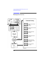
Test, Parameter, and Pass/Fail Limit (Specification) Descriptions
Testing Strategy
Testing Strategy
Running the call processing tests first will verify the mobile unit’s
functionality before running tests that find a parametric problem such
as distorted audio. The following strategy is a suggested testing
organization.
1. Make connections as described in chapter 2. You will have to connect and
use the handset for the call processing tests later in this strategy.
2. Load the HP 11807A Option 009 Software from the card into the test
system. See chapter 1, "Getting Started with FW Above Rev. A.14.00," on
page 15 or chapter 2, "Getting Started with FW Below Rev. A.14.00," on
page 31. Load the Procedure named ‘CALL_PR’ from the card.
3. Run the test procedure. TEST_01 CP Registration, TEST_21 CPA
Origination, or TEST_35 CPD Origination should be the first test in your
test procedure sequence because these tests obtain the mobile identification
number (MIN) of the UUT. The Test Set requires a MIN to page the UUT.
Once a MIN is obtained from a UUT, it is retained by the Test Set until a
new MIN is obtained. Therefore, the Registration or Origination test needs
to be performed only once on each UUT. Subsequent test procedures do not
need to start with TEST_01 CP Registration, TEST_21 CPA Origination,
or TEST_35 CPD Origination.
If the first test in a test procedure sequence is not TEST_01 CP
Registration, TEST_21 CPA Origination, TEST_35 CPD Origination, or
TEST_25 Manual Flow Chart, and the MIN from the UUT has not been
previously obtained by the Test Set, then the Test Set will prompt the user
for the UUT phone number. The Test Set will then create the MIN from
the phone number (see also descriptions for Parameter 1 AA Enter Ph#
[0=If Needed,1=Always,Here], and Parameter 2 AB MIN From
[0=RECC, 1=All 0’s, 2=Phone #].
Run analog call processing (CPA) tests for verification that the mobile unit
is functional. Also, these tests only use the mobile unit’s antenna to test
system’s RF IN/OUT connection (no audio connections are required). You
may also select the digital call processing (CPD) tests if you wish.
130
Test, Parameter, and Pass/Fail Limit (Specification) Descriptions
Testing Strategy
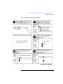
a
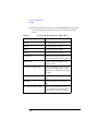
Access the Order of Tests (or Edit Seqn) screen as described in
Changing the Order of Tests (Edit Sequence) in chapter 3.
b Follow the procedure to edit the sequence and create or view the test
sequence with the following tests in the order presented:
Test Name
Purpose
TEST_01 - CP Registration
Verify that mobile is functioning (only
RF and dc power connections required)
and returns the units phone number, serial
number and power class
TEST_02 - CPA Page
Simulates an analog call to the mobile
unit
TEST_20 - CPA Release
Releases the mobile unit
TEST_21 - CPA Origination
Simulates an analog call from the mobile
unit
TEST_ 30 - CPD Page
Simulates a digital call to the mobile unit
TEST_36 - CPD Release
Releases the mobile unit
TEST_35 - CPD Origination
Simulates a digital call from the mobile
unit
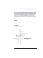
c
Establish whether the mobile unit uses A control channels (channels
313 to 333), B control channels (channels 334 to 354) or both A and B
control channels.
d Check and update, the CPA Control Channel number that is
required by the mobile unit. See "Changing the Test Parameters" on
page 87.
• Select the CPA Control Channel and enter the correct control
channel if necessary.
e The handset is connected.
131
Test, Parameter, and Pass/Fail Limit (Specification) Descriptions
Testing Strategy
f
Press TESTS to access the TESTS screen and then press Run Test.
You are now running the tests in the sequence entered earlier. As the
results are reported on the CRT of the test system you will be able to
better isolate and determine the cause of any problems. Save this group
of call processing tests as a test procedure, see "Saving a Test
Procedure" on page 89. You may also want to add the digital call
processing tests to this test procedure.
4. Add transmitter and receiver tests to your test procedure, through the
Order of Tests function. You may save the test procedure, see
"Saving a Test Procedure" on page 89. Some of these tests require audio
connections. Be sure to make the appropriate audio connections specific to
your radio.
You may want to add the following tests to your test procedure:
Test Name
Purpose
TEST_04 - TXA RF Power Output
Verify analog transmitter
TEST_07 - TXA Audio Distortion
Verify transmitter audio connection
TEST_18 - RXA SINAD
Verify analog receiver and receiver audio
connection
132
Test, Parameter, and Pass/Fail Limit (Specification) Descriptions
Test Descriptions
Test Descriptions
Tests are a series of measurements. One or more tests make up a
Procedure (see "Procedures" on page 323). While you may change the
tests that make up a Procedure, you may not change the measurements
the test will perform. Be sure and run TEST_01 - CP Registration,
TEST_21 CPA Origination, or TEST_35 CPD Origination, before
other tests to register each UUT unit with the test system. Once a UUT
has been registered with the test system, TEST_01, TEST_21, or
TEST_35 does not need to be performed before other tests.
Standards Used
The tests contained in this Test Package are derived from the EIA/TIA
IS-54 Cellular System Dual-Mode Mobile Station — Base Station
Compatibility Standard, EIA/TIA IS-55 Recommended Minimum
Performance Standards for 800 MHz Dual-Mode Mobile Stations and
the EIA/TIA IS-90 Recommended Minimum Standard for 800 MHz
Dual-Mode Narrowband Analog Cellular Subsriber Units.
Test Nomenclature
•
•
•
•
•
•
•
•
CP - Call Processing, Analog and Digital tests
CPA - Call Processing, Analog tests
CPD - Call Processing, Digital tests
OTA - Other Tests, Analog
RXA - Receiver, Analog tests
RXD - Receiver, Digital tests
TXA - Transmitter, Analog tests
TXD - Transmitter, Digital tests
133
Test, Parameter, and Pass/Fail Limit (Specification) Descriptions
Test Descriptions
TEST_01 - CP Registration
This test reads and decodes the phone’s Reverse Control Channel
(RECC) data and outputs the following registration information:
Phone number.
Serial number in both decimal and hex format.
Power class.
Transmission (continuous or discontinuous).
Bandwidth (20 MHz or 25 MHz).
The test works as follows:
•
•
The test system transmits the Registration ID message repeatedly, with the
value of the REGID field set alternately to 0 and 500. This induces the
phone to register with the test system.
If an error occurs in this test, all testing is stopped.
A CP registration, CPA origination, or CPD origination test must be
run at least once before any call processing tests can be run, otherwise
the operator is prompted to enter the UUT phone number during
testing. After the CP registration, CPA origination, or CPD origination
test is run once it does not need to be run again for the test system to be
able to perform other tests. The registration data is remembered unless
it is erased by loading new test software, registering a different radio,
or executing a SCRATCH C command in IBASIC.
Pass/fail limits Used
None
Parameters used
01. AA Enter Ph#[0=If Needed,1=Always,Here]
02. AB MIN From?[0=RECC, 1=All 0’s, 2=Phone#]
03. CP Control Channel [1:799] or [991:1023]
04. CP Prt RECC RVC Data [0=no 1=yes 2=fail]
28. RXA RF Level for Signaling
134
Test, Parameter, and Pass/Fail Limit (Specification) Descriptions
Test Descriptions
TEST_02 - CPA Page
Initiates a call to the mobile station from the base station. Specifically,
this test does the following:
1. Performs a page to the UUT
2. Performs 3 of 5 majority voting on the Reverse Control Message
3. Performs BCH (Bose-Chaudhuri-Hocquenghem) error detection and
correction of the Reverse Control Message
4. Tests each section of the page response, bit by bit
5. Sends an Initial-Voice-Channel-Designation order to the UUT, directing it
to tune to a voice channel obtained from the Channel Information
(or Edit Freq) table. If the channel number from the table has an L, M,
or U suffix, the phone will be directed to a narrow voice channel. If the
channel number has no suffix, the phone will be directed to a wide voice
channel.
6. Sends an ALERT order to the UUT by way of the Forward Voice Channel
(FVC)
7. Makes a power measurement on the initial voice channel to verify that the
voice channel was obtained. The power measurement result is not displayed
in this test.
Pass/fail limits used
None
Parameters used
01. AA Enter Ph#[0=If Needed,1=Always,Here]
02. AB MIN From?[0=RECC,1=All 0’s,2=Phone#]
03. CP Control Channel [1:799] or [991:1023]
04. CP Prt RECC RVC Data [0=no 1=yes 2=fail]
28. RXA RF Level for Signaling
07. CPA SAT Tone
06. CPA DSAT Vector (for NAMPS narrow channel)
135
Test, Parameter, and Pass/Fail Limit (Specification) Descriptions
Test Descriptions
TEST_03 - TXA Frequency Error
This test measures the difference between the unmodulated carrier
frequency and the assigned carrier frequency. TX frequency error is
measured on a voice channel with voice modulation off, and SAT
modulation on.
The frequency error is expressed in parts-per-million (ppm).
Pass/fail limits used
28. TXA Frequency Error
Parameters used
High and low supply voltages are measured only if an external power
supply has been configured to be used over HP-IB by the test system
and if the Parameter, 15. RT Test at Extreme Settings is set to test at
extremes (1=yes). See "TEST_13 - TXA Current Drain" on page 149
for details on configuring an HP-IB power supply.
12. RT High Supply Voltage
13. RT Low Supply Voltage
14. RT Nominal Supply Voltage
15. RT Test at Extreme Settings [0=no 1=yes]
TEST_04 - TXA RF Power Output
This test measures the power at the output terminals of the transmitter
when the output terminals are connected to a 50[ohm ] load. This test is
performed at the nominal supply voltage and can also be performed
with high and low supply voltages for extreme measurements if a
power supply is configured to the test system.
This test requires a programmable power supply when the high-supply
and low-supply power measurements are performed. Output power is
expressed in dBW or watts by appropriately setting the Parameter 41,
TX Units for Pwr Meas.
Pass/fail limits used
136
Test, Parameter, and Pass/Fail Limit (Specification) Descriptions
Test Descriptions
Normally , all power levels are tested; however, the Parameter 47,
TXA Output Power Levels Tested [BWD #] allows you to select only
the levels you want tested.
11. TX Output Power at Level 0
12. TX Output Power at Level 1
13. TX Output Power at Level 2
14. TX Output Power at Level 3
15. TX Output Power at Level 4
16. TX Output Power at Level 5
17. TX Output Power at Level 6
18. TX Output Power at Level 7
137
Test, Parameter, and Pass/Fail Limit (Specification) Descriptions
Test Descriptions
Parameters used
High and low supply voltages are measured only if an external power
supply has been configured to be used over HP-IB by the test system
and if the Parameter 15, RT Test at Extreme Settings is set to test at
extremes (1=yes). See "TEST_13 - TXA Current Drain" on page 149
for details on configuring an HP-IB power supply.
04. CP Prt RECC RVC Data [0=no 1=yes 2=fail]
11. RT External Path Loss
12. RT High Supply Voltage
13. RT Low Supply Voltage
14. RT Nominal Supply Voltage
15. RT Test at Extreme Settings [0=no 1=yes]
16. RT Use DUPLEX OUT & ANT IN [0=no 1=yes]
41. TX Units for Power Meas [0=dBW 1=Watts]
47. TXA Output Power Levels Tested [BWD #]
TEST_05 - TXA Modulation Deviation Limiting
This test measures the ability of the transmitter circuits to prevent the
transmitter from producing deviations in excess of rated system
deviation. This test measures the Peak+ and the Peak− values of the
instantaneous (INST) and steady state (SS) modulation and indicates
whether or not the modulation is symmetrical. Symmetry is based upon
the difference between positive and negative swings of the carrier at
any level of modulation. Modulation limiting is expressed in kHz;
modulation symmetry is expressed in a percent difference between
positive and negative swings of the carrier.
1. The audio generator’s frequency is set to 1 kHz.
2. The audio generator’s level is set to produce 8 kHz deviation by the UUT
(3 kHz deviation for narrow analog operation).
3. The audio generator’s level is increased by 20 dB.
4. Steps 2 and 3 are repeated 3 times, and the maximum peak frequency
deviation is held and reported.
5. The audio generator’s frequency is stepped from 300 Hz to 3 kHz while the
audio generator’s level is maintained at the 20 dB overdrive. The size of the
138
Test, Parameter, and Pass/Fail Limit (Specification) Descriptions
Test Descriptions
frequency steps is obtained from the Parameter 45, TXA Frequency
Deviation Step Frequency. If this parameter is set to 0, then the test will run
at 1 kHz only. Peak frequency deviation is repeated at each step.
Audio connections from the radio to the test system are required for
this test.
Pass/fail limits used
29. TXA Modulation Limiting
34. TXA NAMPS Modulation Limiting
139
Test, Parameter, and Pass/Fail Limit (Specification) Descriptions
Test Descriptions
Parameters used
High and low supply voltages are measured only if an external power
supply has been configured to be used over HP-IB by the test system
and if the Parameter 15, RT Test at Extreme Settings is set to test at
extremes (1=yes). See "TEST_13 - TXA Current Drain" on page 149
for details on configuring an HP-IB power supply.
12. RT High Supply Voltage
13. RT Low Supply Voltage
14. RT Nominal Supply Voltage
15. RT Test at Extreme Settings [0=no 1=yes]
45. TXA Frequency Deviation Step Frequency
46. TXA Mod Dev Limit 50 Hz HPF [0=off 1=on]
TEST_06 - TXA Audio Frequency Response
This test measures how closely the frequency deviation of the
transmitter follows a 6 dB/octave pre-emphasis slope over a given
frequency range. (This test is intended to be used between the audio
response frequencies of 300 Hz and 3 kHz only.) Audio connections
from the radio to the test system are required for this test.
The test results indicate the flatness of the audio output as frequency is
varied. Audio frequency response is expressed in dB error from the 6
dB/octave pre-emphasis slope.
Background
•
•
Audio frequency response is measured at 2.9 kHz peak deviation for wide
voice channels and 1.5 kHz peak deviation for narrow voice channels.
The frequency response measurement is made with the rms detector and is
made with respect to a 1 kHz reference rate.
Pass/fail limits used
20. TXA Audio Frequency Dev from 6 dB/oct
21. TXA Audio Response Roll >2.5 kHz
Parameters used
42. TXA Audio Response Step Frequency
140
Test, Parameter, and Pass/Fail Limit (Specification) Descriptions
Test Descriptions
TEST_07 - TXA Audio Distortion
This test measures the level of the demodulated carrier’s audio
distortion. Audio connections from the radio to the test system are
required for this test.
The test system does not have expandor circuitry. If your testing
conditions require correction for this situation, you must change the
limits set in the Pass/fail limit 19, TXA Audio Distortion, as required.
Transmitter audio distortion is expressed in percent.
Also, this test uses the C-Message audio filter or the CCITT audio
filter, if it is installed in the test system.
Pass/fail limits used
19. TXA Audio Distortion
Parameters used
None
TEST_08 - TXA Signaling Tone/DST
If the channel is a wide voice channel, this test measures the signaling
tone’s frequency and peak deviation. Since the SAT tone is always on
in this test, deviation is measured with the rms detector, with and
without the signaling tone on. The peak deviation of the signaling tone
is calculated from the two readings. Therefore, test results indicate
peak deviation, not peak+ or peak−.
If the channel is a narrow voice channel, the peak deviation of the
digital signaling tone (DST) is measured and the DST sequence is
decoded and reported in hexadecimal.
Since this test is run in the “maintenance mode” where the base station
is waiting for an answer, the operator must press the send key on the
handset to exit the test.
Background
141
Test, Parameter, and Pass/Fail Limit (Specification) Descriptions
Test Descriptions
The signaling tone (ST) is a 10-kHz tone generated by the phone on a
wide voice channel and is transmitted to the cell site for confirming
orders (Alert, Audit, Change Power, etc.), and for signaling flash and
release requests.
The digital signaling tone (DST) performs the same function on the
narrow voice channel that ST performs on the wide voice channel. The
DST is a 24-bit digital sequence transmitted continuously at 200 NRZ
bits/second and produces an average peak deviation of 700 Hz. Each
DST sequence is the logical inverse of a corresponding digital
supervisory audio tone (DSAT) sequence.
CAUTION:
If the channel is a narrow voice channel, an open microphone on your UUT can
affect the results of this test. If your UUT has an open microphone, this test
must be performed in a quiet environment.
142
Test, Parameter, and Pass/Fail Limit (Specification) Descriptions
Test Descriptions
Pass/fail limits used
32. TXA NAMPS DSAT Deviation
37. TXA Signaling Tone Deviation
38. TXA Signaling Tone Frequency
Parameters used
None
TEST_09 - TXA FM Hum and Noise
This test measures the ratio of residual frequency modulation to the
standard test modulation. Audio connections from the radio to the test
system are required for this test.
The test system does not have expandor circuitry. If your testing
conditions require correction for this situation, you must change the
limits set in the Pass/fail limit 27, TXA FM Hum and Noise, as
required.
FM hum and noise is expressed in dB, from the formula:
−20 × Log(Reference Deviation ÷ Present Deviation)
CAUTION:
An open microphone on your UUT can affect the results of this test. If your
UUT has an open microphone, this test must be performed in a quiet
environment.
Pass/fail limits used
27. TXA FM Hum and Noise
Parameters used
None
143
Test, Parameter, and Pass/Fail Limit (Specification) Descriptions
Test Descriptions
TEST_10 - TXA SAT/DSAT
If the channel is a wide voice channel, this test measures the frequency
error and peak deviation of the three SAT tones. The rms detector is
used for measuring SAT deviation. The SAT deviation is then
converted to a peak reading.
Also, this test uses the 6 kHz BPF, Option 014 if it is installed. (If there
is no filter and the UUT has an open microphone, the readings may be
affected by background noise. In this case, mute the handset.)
If the channel is a narrow voice channel, the test system transmits
DSAT sequence #3=25AD4D in hexadecimal. The peak deviation of
the DSAT returned by the phone is measured and reported. An eyepattern test is performed on the DSAT and the closure and phase jitter
are measured and reported.
Background
The supervisory audio tones (SAT) are the 5970, 6000, and 6030 Hz
tones used for signaling. One of the three tones is added to the wide
channel voice transmission by a cell site. The radio then detects the
tone and modulates the transmitted voice-channel carrier with a
constant (relative) phase tone which is regenerated from the received
tone to establish a closed loop between the mobile (cellular radio) and
the cell site. Transmission of the SAT is suspended during transmission
of wideband data on the reverse voice channel (RVC), but is not
suspended when the signaling tone (ST) is sent.
The digital supervisory tone (DSAT) performs the same function on the
narrow voice channel that the SAT performs on the wide voice
channel. The DSAT is a 24-bit digital sequence transmitted
continuously at 200 NRZ bits/second and produces an average peak
deviation of 700 Hz. Seven different sequences are defined.
144
Test, Parameter, and Pass/Fail Limit (Specification) Descriptions
Test Descriptions
CAUTION:
An open microphone on your UUT can affect the results of this test. If your
UUT has an open microphone, this test must be performed in a quiet
environment.
Pass/fail limits used
31. TXA NAMPS DSAT Closure
32. TXA NAMPS DSAT Deviation
33. TXA NAMPS DSAT Phase Jitter
35. TXA SAT Deviation
36. TXA SAT Frequency Error
Parameters used
06. CPA DSAT Vector
TEST_11 - TXA RVC Data Deviation
This test provides three possible modes of operation, determined by
parameter 50 TXT trnsient/ss data [0=tran 1=bth 2=ss].
The first method, selected by setting parameter 50 to 0=tran, measures
the Peak+ and Peak− frequency deviation of the data in the entire
Reverse Voice Channel (RVC) burst to ensure that it is within the
specified limits.
The entire burst is tested by sending the FVC message 5 times while
the peak+ hold detector is on, and another 5 times while the peak− hold
detector is on.
The second method, selected by setting parameter 50 to 1=bth, first
performs the test on just the steady state portion of the RVC data
signal, followed by a test of the entire signal (described above).
The steady state portion of the test is performed by measuring the RVC
data signal between 20 msec and 50 msec following the beginning of
the data burst. The peak + and − results are compared to values in pass/
fail limit 39 TX wideband data deviation. The results of the transient
portion of the test are compared to values in the pass/fail limit 50 TX
wideband data deviation transient.
145
Test, Parameter, and Pass/Fail Limit (Specification) Descriptions
Test Descriptions
The third method, selected by setting parameter 50 to 2=ss, performs
the test on just the steady state portion of the RVC data signal (as
described above).
NOTE:
In all three methods, the UUT should blank the SAT tone before sending the
RVC message; therefore, SAT deviation should not be included in the
deviation measurement. If the UUT has an open microphone, the readings
may be affected by background noise. In this case, mute the handset.
NOTE:
The second and third test methods use trigger delay capabilities and can only
be performed on an HP 8920B. If you are using an HP 8920A with HP 11807A,
the software will ignore the setting of parameter 50 and perform the test using
the first method only.
Using the first method, Hewlett-Packard Company has found that
some cellular telephones fail this test because the telephones produce
a carrier frequency transient at the beginning of wideband data
transmission. This causes the peak frequency deviation to exceed the
maximum specification of ±8 kHz ±10% (or a total of ±8.8 kHz)
specified in the EIA/TIA IS-55 Standard. This transient typically
occurs during the first 10 milliseconds of the wideband data
transmission from the telephone. The HP 11807A Option 009
software measures the FM peak deviation during the entire period
while the telephone transmits its data and holds and displays only the
highest positive and negative peaks detected. The HP Test Set has a
fast peak detector which captures the peak deviation that occurs over
the entire period, including the deviation that occurs in the first 10
milliseconds. The measurement method conforms to the EIA/TIA
IS-55 Standard.
146
Test, Parameter, and Pass/Fail Limit (Specification) Descriptions
Test Descriptions
Applications:
RVC data is Manchester-encoded data that is used for cellular system
signaling and control. Manchester encoding is accomplished by
transforming each NRZ (non-return to zero) binary one to a zero-to-one
transition and each NRZ binary zero to a one-to-zero transition. The
data stream is then used to modulate the transmitter carrier using direct,
binary, frequency-shift keying (FSK).
On the wide voice channels, the data rate is 10 kilobits/second and the
nominal peak transmitted deviation is 8 kHz. All other modulation
sources to the transmitter are inhibited when the data is transmitted
(”blank and burst”).
On the narrow voice channels, the data rate is 100 bits/second and the
nominal peak transmitter deviation is 700 Hz. The data words are
inserted into the DSAT data stream. The transmitter is modulated
simultaneously by voice audio and the data stream.
Pass/Fail Limits Used
32 TX NAMPS DSAT deviation
39 TX wideband data deviation
50 TXT wideband data deviation transient
Test Parameters Used
50 TXT trnsient/ss data [0=tran 1=bth 2=ss]
TEST_12 - TXA Compressor Response
This test measures the compressor’s zero reference deviation and
operating range. For every 2 dB change in input level, there should be a
nominal output level change of 1 dB. Audio connections from the radio
to the test system are required for this test.
147
Test, Parameter, and Pass/Fail Limit (Specification) Descriptions
Test Descriptions
Compressor response is expressed in dB of tracking error over the
indicated operating range.
•
•
•
The deviation is then set to 2.9 kHz (1.5 kHz for narrow analog) and a
reference is taken with the rms detector. The voltage used to achieve 2.9
kHz deviation is displayed as “TXA cmp volt for 2.9 kHz dev”.
If Parameter 43, TXA Compressor Step Level, is greater than 0, the point
at which the phone starts to limit is determined. This limiting point is
displayed as “TXA compression point” and the result is displayed in dB
relative to the reference level. The input is then varied from a level of −30
dB below the reference level up to the compression point level in steps set
by Parameter 43, TXA Compressor Step Level. The RMS deviation is
measured and the compressor response relative to the reference is
calculated.
If Parameter 43, TXA Compressor Step Level, is less than 0, then the input
is varied from a high level of +25 dB above the measured reference level to
a level of −30 dB below the measured reference level in steps set by the
Parameter 43, TXA Compressor Step Level. The rms deviation is measured
and the compressor response relative to the reference is calculated. The
compressor typically limits relative inputs ≥17.6 dB; therefore, the Pass/fail
limit 22, TXA Compressor Min Out @>17.6 dB input, is used to specify the
lower limit for relative output deviation when the relative input deviation is
>17.6 dB.
Also, this test uses the C-Message audio filter or the CCITT audio
filter, if it is installed in the test system.
148
Test, Parameter, and Pass/Fail Limit (Specification) Descriptions
Test Descriptions
Background
A compressor is used in the phone’s voice input circuitry to decrease
the variability of the modulation due to volume changes from the
talker. In combination with an expandor in the cell site receiver, this
provides improved signal-to-noise-ratio in the demodulated audio.
Pass/fail limits used
22. TXA Compressor Min Out @>17.6 dB input
Parameters used
43. TXA Compressor Step Level
TEST_13 - TXA Current Drain
This test measures the average power supply current drawn by the UUT
when it is operating. The transmitter’s current drain is expressed in
amps. This test can measure current drain using two methods. The test
software first looks to see if an HP-IB power supply has been
configured in the External Devices (or Edit Config) screen. If one has
been configured, the current drain will be measured via the
programmable power supply over HP-IB, see the procedure for
Configuring an HP-IB Power Supply that follows. If an HP-IB power
supply is not available, (HP-IB power supply not configured in
External Devices (or Edit Config) screen) the software measures
current drain through the rear-panel dc current measurement capability
of the test system, see the procedure Configuring the Rear Panel
dc-Current Measurement that follows.
This test is not specified by EIA/TIA standards.
149
Test, Parameter, and Pass/Fail Limit (Specification) Descriptions
Test Descriptions
A Hewlett-Packard programmable dc power supply is required for this
test if an HP-IB power supply is to be configured. A power supply with
sufficient voltage and current capabilities from the following series
must be used:
•
•
•
•
HP 664xA
HP 665xA
HP 667xA
HP 668xA
Configuring an HP-IB Power Supply
The following must be done to setup the power supply through the
HP-IB on the test system:
1. Connect the power supply’s HP-IB interface to the test system’s HP-IB
interface with an appropriate length HP-IB cable.
2. Access the test system’s TESTS screen by pushing the TESTS key on the
front panel.
3. Select External Devices from the SET UP TEST SET’’ list (or Edit
Cnfg from the Test Function field).
4. Position the cursor to the Inst# field and select it.
5. Rotate knob until an empty Calling Name field appears, and select it.
6. Using the list of characters in the Choices menu , enter the words Power
Supply in the Calling Name field. Select Done when complete.
7. Position the cursor to the Model field and select it (optional).
8. Using the DATA keypad and list of characters in the Choices menu, enter
the Model # and press ENTER.
9. Position the cursor to the Addr (address) field and select it.
10. Using the DATA keypad, enter 7XX (X = 1 through 30) for the HP-IB
address and press ENTER.
11. From the To Screen menu, select More.
12. From the Choices menu, select IO CONFIG.
13. Position the cursor to the Mode field and select it.
14. From the Choices menu, select Control.
15. Press TESTS to return to TESTS screen. The power supply is now ready to
be controlled by the test system when the current drain test is run.
Configuring the Rear-Panel dc-Current Measurement
1. The dc-current measurement must be zeroed before the measurement.
Access the test system’s TESTS screen by pushing the TESTS key on the
150
Test, Parameter, and Pass/Fail Limit (Specification) Descriptions
Test Descriptions
front panel.
2. Position the cursor to the AF ANL field under To Screen and select it.
3. Position the cursor to the dc Current field and select it (this should be
done before any current is applied to the test system’s measurement
terminals). The dc-current measurement is now zeroed.
4. Use a power supply that provides the appropriate voltage and current for
your UUT.
5. Connect the positive lead of the power supply to the positive terminal
(banana) of the dc-current measurement connector on the lower-left rear
panel of the test system.
6. Connect the negative terminal (banana) of the dc-current measurement
connector to the positive terminal of the mobile unit’s supply input.
7. Connect the negative terminal of the power supply directly to the negative
terminal of the mobile unit’s supply input.
8. The software will automatically measure the current passing through the
rear-panel connection. Be sure that there is no HP-IB power supply
configured in the External Devices (or Edit Config) screen of the test
system, see the procedure above for Configuring an HP-IB Power Supply.
Pass/fail limits used
24. TXA Current Drain @levels 0-3
25. TXA Current Drain @levels 4-7
Parameters used
04. CP Prt RECC RVC Data [0=no 1=yes 2=fail]
44. TXA Current Drain Levels Tested [BWD #]
TEST_14 - RXA Expandor
This test measures the expandor’s zero reference level and operating
range. For every 1 dB change in input level, there should be a nominal
output level change of 2 dB. Audio connections from the radio to the
test system are required for this test.
Expandor response is expressed in dBV for the zero reference level,
and in dB for the tracking error over the indicated operating range.
•
The expandor response is measured at a 1 kHz rate and an RF input level of
151
Test, Parameter, and Pass/Fail Limit (Specification) Descriptions
Test Descriptions
•
•
•
•
−50 dBm.
A 2.9 kHz (1.5 kHz for narrow analog operation) deviation is applied and
the “zero crossing” of the receiver is measured. This value is retained as the
reference level.
For NADC phones the input is varied from a high level of +10.6 dB above
the measured reference level to a level of −21 dB below the measured
reference level in steps set by the Parameter 21, RXA Expandor Step Level.
For AMPS and NAMPS phones, the input is varied from a high level of +12
dB above the measured reference level to a level of −21 dB below the
measured reference level. The rms deviation is measured and the expandor
response relative to the reference is calculated.
Deviation is varied over the range and the expandor response relative to the
“zero crossing” point is calculated.
The sweep will go from a high level (+10.6 dB for NADC phones) to a low
level (−21 dB) if the sign of the step level set by Parameter 21, RXA
Expandor Step Level is negative. The sweep will go from a low to high
level if the sign of Parameter 21 is positive.
Background
An expandor is used to provide the complement of the compressor in
the cell site transmitter. Together, the compressor and expandor
provide improved signal-to-noise-ratio in the demodulated audio.
152
Test, Parameter, and Pass/Fail Limit (Specification) Descriptions
Test Descriptions
Pass/fail limits used
04. RXA Expandor Track Error <0
05. RXA Expandor Track Error >0
06. RXA Expandor Zero Reference Level
08. RXA NAMPS Expandor Zero Reference Level
Parameters used
21. RXA Expandor Step Level
TEST_15 - RXA Audio Frequency Response
This test measures the ability of the receiver’s audio output circuitry to
follow a 6 dB/octave de-emphasis curve, as well as to follow an audiobandpass response. The Parameter 28, RXA RF Level for Signaling is
applied with a constant deviation. The modulation rate is swept over
the audio frequency-response range in steps determined by the
Parameter 20, RXA Audio Response Step Frequency.
Audio connections from the radio to the test system are required for
this test. Receiver audio frequency response is expressed in dB error
from a 6 dB/octave curve.
•
•
•
•
•
A −50 dBm RF signal is applied to the receiver’s antenna.
The −50 dBm RF signal is modulated to deviate to 2.9 kHz at a 1 kHz rate
with a SAT tone present and a reference reading is made.
The frequency rate is then swept over the desired range and the response
measured.
If the compandor is always on, a 2:1 correction is applied to the measured
results.
Narrow analog operation uses 1.5 kHz deviation and DSAT.
Pass/fail limits used
02. RXA Audio Response Dev from −6 dB/oct R1
03. RXA Audio Response Dev from −6 dB/oct R2
Parameters used
10. RC Compandor is Always On [0=no 1=yes]
20. RXA Audio Response Step Frequency
153
Test, Parameter, and Pass/Fail Limit (Specification) Descriptions
Test Descriptions
TEST_16 - RXA Audio Distortion
This test measures the distortion from the receiver when a standard test
tone is applied to the radio. Audio connections from the radio to the test
system are required for this test.
Also, this test uses the C-Message audio filter or the CCITT audio filter
if it is installed in the test system.
•
•
•
A −50 dBm RF signal is applied to the receiver’s antenna.
The −50 dBm RF signal is modulated to deviate to 8 kHz at a 1 kHz rate
with a 6000 Hz SAT tone present.
Narrow analog operation uses 3 kHz deviation and DSAT.
Pass/fail limits used
01. RXA Audio Distortion
Parameters used
None
TEST_17 - RXA Hum and Noise
This test measures the ratio, expressed in dB, of:
❒ The residual audio output in the absence of modulation,
❒ To the rated audio output.
Audio connections from the radio to the test system are required for
this test.
Also, this test uses the C-Message audio filter or the CCITT audio
filter, if it is installed in the test system.
•
•
•
•
A −50 dBm RF signal is applied to the receiver’s antenna.
The −50 dBm RF signal is modulated to deviate to 8 kHz at a 1 kHz rate
with a SAT tone present.
The SAT tone is always on during this test.
Narrow analog operation uses 3 kHz deviation and DSAT.
Pass/fail limits used
07. RXA Hum and Noise
154
Test, Parameter, and Pass/Fail Limit (Specification) Descriptions
Test Descriptions
Parameters used
None
TEST_18 - RXA SINAD
This test sets and measures the ratio, expressed in dB, of:
•
•
Signal + Noise + Distortion,
to Noise + Distortion.
The receiver’s SINAD is measured at the RF level specified by the
Parameter, 29, RXA RF Level for SINAD. Audio connections from the
radio to the test system are required for this test.
Receiver SINAD is measured at the receiver’s audio output. This
measurement differs from a distortion measurement in that it is
conducted at low RF input levels where the noise contribution is
significant.
This test is intended to measure receiver sensitivity. Receivers are
typically required to provide at least 12 dB SINAD (less than 25%
noise and distortion) for RF input levels below 1 microvolt.
•
•
•
The RF signal (level set by the Parameter 29, RXA RF Level for SINAD)
is modulated to deviate to 8 kHz at a 1 kHz rate with a SAT tone present.
The measurement is repeated at high and low supply voltages if the
Parameter 15, RT Test at Extreme Settings, is set to 1.
Narrow analog operation uses 3 kHz deviation and DSAT.
Pass/fail limits used
10. RXA SINAD
155
Test, Parameter, and Pass/Fail Limit (Specification) Descriptions
Test Descriptions
Parameters used
High and low supply voltages are measured only if an external power
supply has been configured to be used over HP-IB by the test system
and if the Parameter 15, RT Test at Extreme Settings is set to test at
extremes (1=yes). See "TEST_13 - TXA Current Drain" on page 149
for details on configuring an HP-IB power supply.
12. RT High Supply Voltage
13. RT Low Supply Voltage
14. RT Nominal Supply Voltage
15. RT Test at Extreme Settings [0=no 1=yes]
26. RXA NAMPS RF Level for SINAD
27. RXA NAMPS RF Level for SINAD at Extremes
29. RXA RF Level for SINAD
30. RXA RF Level for SINAD at Extremes (used only if extreme settings
= yes)
TEST_19 - RXA FVC Order Message Error Rate
This test simulates a Forward Voice Channel (FVC) order message
being sent from a cell site to the cellular radio and measures the Order
Message Error Rate.
The test works as follows:
•
•
•
A Forward Voice Channel (FVC) audit message is sent 100 times and the
number of acknowledgments from the UUT is counted.
The RF level is set by the Parameter 22, RXA FVC Message Error Rate RF
Level.
If the UUT misses 10 acknowledgments in a row the test terminates.
FVC order message error rate is expressed in %.
Pass/fail limits used
09. RXA Order Message Error Rate (OMER)
Parameters used
22. RXA FVC Message Error Rate RF Level
156
Test, Parameter, and Pass/Fail Limit (Specification) Descriptions
Test Descriptions
TEST_20 - CPA Release
This test provides the necessary commands to release the mobile unit.
The test works as follows:
•
•
•
•
The mobile unit is set onto a voice channel (if not already on a voice
channel).
A release message is sent from the test system.
Power is monitored continuously until the power drops below −25 dBW or
until 6 seconds has passed, whichever occurs first.
The test fails if the 6 second limit is reached.
Pass/fail limits used
None
Parameters used
16. RT Use DUPLEX OUT & ANT IN [0=no 1=yes]
41. TX Units for Pwr Meas [0=dBW 1=Watts]
TEST_21 - CPA Origination
This test simulates a call from the cellular phone to the base station
(cell site) by putting the phone in service and having the operator
originate a call from the handset. Specifically, this test performs the
following:
1. The test system simulates a control channel.
2. The operator is instructed to dial 123 123 4567 after the UUT has service.
(Service is indicated by the NO SERVICE light going off or the SERVICE
light illuminating on the UUT.)
3. Performs 3 of 5 majority voting on the Reverse Control Message
4. Performs BCH error detection and correction of the Reverse Control
Message, Wideband data
5. Tests each section of the origination message, bit by bit
6. Sends an Initial-Voice-Channel-Designation order to the UUT directing it
to tune to a voice channel obtained from the Channel Information
(or Edit Freq) table.
157
Test, Parameter, and Pass/Fail Limit (Specification) Descriptions
Test Descriptions
7. Makes a power measurement on the initial voice channel to verify that the
voice channel was obtained. The power level measurement result is not
displayed in this test.
It is not necessary to register the phone with the Test Set by running
TEST_01 CP Registration before running this test. TEST_21 CPA
Origination will read the UUT’s Mobile Identification Number (MIN)
and the Test Set will retain it for use in performing other tests.
If the channel number from the table has an L, M, or U suffix, the
phone will be directed to a narrow voice channel. If the channel
number has no suffix, the phone will be directed to a wide voice
channel.
Pass/fail limits used
None
Parameters used
03. CP Control Channel
04. CP Prt RECC RVD Data
28. RXA RF Level for Signaling
07. CPA SAT Tone
06. CPA DSAT Vector (for NAMPS narrow channel)
158
Test, Parameter, and Pass/Fail Limit (Specification) Descriptions
Test Descriptions
TEST_22 - OTA No Audio Functional
This test contains a collection of tests designed to provide a quick
evaluation of the UUT without the need to make audio connections
from the UUT to the test system. The following tests are included:
TEST_21 - CPA Origination
TEST_03 - TXA Frequency Error
TEST_04 - TXA RF Power Output
TEST_08 - TXA Signaling Tone/DST
TEST_10 - TXA SAT/DSAT
TEST_11 - TXA RVC Data Deviation
TEST_27 - CPA Hook Flash
RXA Tones Functional
RXA SINAD Functional
TXA Microphone Functional
The first seven tests in the above list are described individually in this
chapter. The final three tests are available only as part of this test and
they work as follows:
•
•
•
When prompted, the operator is required to listen for tones from the
receiver and then select whether the test passed or failed. The pass/fail
decision is qualitative, and is usually based on whether the tones are heard
clearly.
When prompted, the operator is required to listen to a 1 kHz tone that is
modulated on a low power level carrier signal. The power level of the
carrier signal is set by Parameter 29, RXA RF Level for SINAD. The
operator must select whether the test passed or failed. The pass/fail decision
is qualitative and is usually based on whether the 1 kHz tone could be heard
adequately among the static.
The operator is required to whistle into the transmitter, to observe the
deviation on the test system, and then select whether the test passed or
failed. The pass/fail decision is qualitative, and is usually based on whether
the change in deviation corresponds with the amplitude of the whistle into
the transmitter.
Pass/fail limits used
See the individual tests for pass/fail limits used.
159
Test, Parameter, and Pass/Fail Limit (Specification) Descriptions
Test Descriptions
Parameters used
26. RXA NAMPS RF Level for SINAD
28. RXA RF Level for Signaling
29. RXA RF Level for SINAD
See the individual tests for parameters used.
TEST_23 - TXA Quick General
These tests are designed to provide you with a quick evaluation of the
cellular radio’s transmitter’s capabilities. Audio connections from the
radio to the test system are required for this test. The following tests
are included:
TEST_03 - TXA Frequency Error
TEST_04 - TXA RF Power Output
TEST_05 - TXA Modulation Deviation Limiting
TEST_06 - TXA Audio Frequency Response
TEST_07 - TXA Audio Distortion
TEST_08 - TXA Signaling Tone/DST
TEST_09 - TXA FM Hum and Noise
TEST_10 - TXA SAT/DSAT
TEST_11 - TXA RVC Data Deviation
TEST_12 - TXA Compressor Response
See the individual tests for descriptions.
Pass/fail limits used
See the individual tests for pass/fail limits used.
Parameters used
See the individual tests for parameters used.
160
Test, Parameter, and Pass/Fail Limit (Specification) Descriptions
Test Descriptions
TEST_24 - RXA Quick General
These tests are designed to provide you with a quick evaluation of the
cellular radio’s receiver’s capabilities. Audio connections from the
radio to the test system are required for this test. The following tests
are performed:
TEST_14 - RXA Expandor
TEST_15 - RXA Audio Frequency Response
TEST_16 - RXA Audio Distortion
TEST_17 - RXA Hum and Noise
TEST_18 - RXA SINAD
See the individual tests for descriptions.
Pass/fail limits used
See the individual tests for pass/fail limits used.
Parameters used
28. RXA RF Level for Signaling
See the individual tests for parameters used.
TEST_25 - CP Manual Flow Chart
This test displays a flow-chart representing a cellular phone as it gains
access to a system. It operates with AMPS, NAMPS, and NADC dualmode phones. Once you have established a voice channel using the
flow chart for AMPS and NAMPS phones, you can test cellular-radio
functions including hand-offs, power level changes, SAT\DSAT
changes, hook flashes, and clear the system. At each stage, reversechannel data is displayed for analysis, along with measurements of
power, frequency error, and deviation.
For NADC dual-mode phones, you can establish either a voice channel
(analog) or traffic channel (digital), hand-off between analog and
digital channels, and change power levels. The system can measure
digital phone parameters including EVM, power, frequency error, and
channel quality.
161
Test, Parameter, and Pass/Fail Limit (Specification) Descriptions
Test Descriptions
IMPORTANT
NOTE
For accurate power measurements of an NADC dual-mode phone in “digital”
mode, run the TXD Calibrate RF Power test prior to running CP Flow Chart.
Calibration data is retained as long as the test procedure being run is
present in memory. If you change the test software in the test system
you should rerun this calibration. You should also rerun this
calibration if you change the test setup (test hardware or cables) or
the ambient temperature by more than 5° F.
The calibration is done across the entire cellular band so that all
channels will be calibrated.
If the digital power measurement is not calibrated, the digital power
measurement accuracy is degraded by as much as 1 dB.
162
Test, Parameter, and Pass/Fail Limit (Specification) Descriptions
Test Descriptions
Running the MANUAL test procedure
•
At the beginning of this test, the test system simulates a control channel.
The cellular phone must tune to this control channel and decode the data
stream in order to obtain service. When the phone succeeds at obtaining
service, the NO SERVICE indicator on the phone will turn-off or the
SERVICE light will illuminate. If NO SERVICE continues, try changing
the control channel to the other band by selecting the Cntl Chan field and
entering the appropriate channel number.
•
When the cellular phone first obtains service, you may originate a call by
dialing a phone number and pressing SEND, or you may perform a
registration by pressing the softkey on the Test Set corresponding to
register. You must originate a call, or perform a registration before paging
the phone. The origination and registration provide the phone number of the
UUT to the Test Set.
•
•
To register the phone, select the Register field.
•
To originate a call from an AMPS or NAMPS phone, dial a phone
number and press the phone’s SEND.
You can perform a page after you register the phone or you have previously
performed an origination and the phone indicates service. You can page or
originate onto an analog voice channel, or digital traffic channel provided
you are testing an NADC phone.
If you attempt a digital page or digital origination on a non-NADC phone,
a message will be displayed indicating that you cannot page or originate a
non-NADC phone to a digital traffic channel.
After a page or origination is attempted, the digital capability of the phone
is determined by the software. If the phone is determined to not have
digital capability, the software will no longer present the operator with the
option of performing a digital page or digital origination. This will remain
true until a registration is performed, or a call is originated with an NADC
phone.
•
To page an AMPS or NAMPS phone, select the Anl Page field.
•
To page an NADC dual-mode phone and establish an analog voice
channel, select the Anl Page field.
163
Test, Parameter, and Pass/Fail Limit (Specification) Descriptions
Test Descriptions
•
•
To page an NADC dual-mode phone and establish a digital traffic
channel, select the Anlg/Dig field followed by the Dig Page field.
•
To originate an AMPS or NAMPS phone, dial a number and press the
phone’s SEND key.
•
To originate an NADC phone and establish an analog voice channel,
dial a number and press the phone’s SEND key.
•
To originate an NADC dual-mode phone and establish a digital traffic
channel, select the Anlg/Dig field so that dig orig is displayed on
the flow chart, then, dial a number and press the phone’s SEND key.
Once you establish either a voice or traffic channel, refer to the flow-chart
on the screen and the associated fields to the right of the screen for
operating functions.
Analog and Digital functions
•
chng chan allows you to change cellular phone channels. For NADC
dual-mode phones, you can hand-off analog-to-analog, analog-to-digital,
digital-to-digital, and digital-to-analog channels.
•
chng pwr allows you to change cellular phone transmit power.
•
clear ls allows you to clear the land station (ls). This terminates the
connection from the land station.
•
clear ms allows you to clear the mobile station (ms). This terminates the
connection from the mobile station.
•
Quit allows you to exit the test.
Analog operation only functions:
•
chng sat allows you to change the Supervisory Audio Tone (SAT).
•
chng dsat allows you to change the digital supervisory audio tone
(DSAT) for NAMPS phones.
•
DTMF allows you to measure the frequency error of the high and low tones
from the DTMF generator in the phone.
•
maintnce allows you to run a maintenance check of the phone’s signaling
164
Test, Parameter, and Pass/Fail Limit (Specification) Descriptions
Test Descriptions
tone frequency and deviation.
•
Hook FLSH allows you to transmit a hook flash number from the phone,
receive it, and display it on the test system.
Digital (NADC dual-mode) only functions:
•
chan qual allows you to measure the channel quality of the phone. This
measurement returns the BER interval and RSSI of the current channel as
reported by the phone. The operator is prompted for the power level
transmitted to the phone for this test. The default value is defined by the
Parameter 28, RXA RF Level for Signaling found in the parameter list.
•
Talk Back allows you to test the operation of a digital transmit and
receive channel. This test requires you to speak into the phones’
microphone and listen to what you said.
•
Talk Time allows you to enter the desired Talk Back duration.
•
EVM 1 allows you to change the EVM measurement result field from
ten-burst EVM to single-burst EVM measurements.
•
EVM 10 allows you to change the EVM measurement result field from
single-burst EVM to ten-burst EVM measurements.
Pass/fail limits used
None (since this test only monitors there are no pass/fail limits applied to
the results).
165
Test, Parameter, and Pass/Fail Limit (Specification) Descriptions
Test Descriptions
Parameters used
02. AB MIN From?[0=RECC,1=All 0’s,2=Phone#]
03. CP control channel [1:799] or [991:1023]
04. CP Prt RECC RVC Data [0=no 1=yes 2=fail]
06. CPA DSAT vector [0 thru 6]
07. CPA SAT Tone
08. CPD Talkback time [1:31]
09. CPD wait for hand-off
11. RT External Path Loss
16. RT Use DUPLEX OUT & ANT IN [0=no 1=yes]
17. RTD Active Slot [1:3]
18. RTD Analyzer Trigger Delay [0:971]
19. RTD DVCC [1:255]
28. RXA RF Level for Signaling
33. RXD Number of Slots to Demod [1:1555]
36. RXD Sensitivity RF Level
41. TX Units for Power Meas
TEST_26 - TXA Switch Channels
This test measures transmitter’s frequency error, power, and SAT
frequency error over a range of channels defined by Parameter 37, TX
Switch Channels Start Channel, Parameter 38, TX Switch Channels
Step Channel, and Parameter 39, TX Switch Channels Stop Channel.
The test works as follows:
•
•
•
•
•
The UUT’s channel number is changed over the desired range indicated by
above parameters.
The channels will all be wide voice channels or they will all be narrow
voice channels as determined by the currently active entry in the Channel
Information (or Edit Freq) table.
For each wide channel, the TX output power (at power level 0 only), RF
frequency error, and SAT frequency error is measured.
For each narrow channel, the TX output power and RF frequency error are
measured and the DSAT sequence coming from the phone is decoded and
displayed.
Each time the channel is changed, the SAT frequency is changed to the next
valid SAT tone or DSAT value.
166
Test, Parameter, and Pass/Fail Limit (Specification) Descriptions
Test Descriptions
Pass/fail limits used
11. TX Output Power at Level 0
28. TXA Frequency Error
36. TXA SAT Frequency Error
Parameters used
06. CPA DSAT Vector [0 thru 6]
07. CPA SAT Tone
16. RT Use DUPLEX OUT & ANT IN
37. TX Switch Channels Start Channel
38. TX Switch Channels Step Channel
39. TX Switch Channels Stop Channel
41. TX Units for Pwr Meas [0=dBW 1=Watts]
TEST_27 - CPA Hook Flash
This test verifies that the correct hook-flash number (3 digits) is
correctly sent by the cellular radio.
The test works as follows:
1. A voice channel is established.
2. The operator is prompted to dial a 3-digit number and press the SEND key
on the UUT.
3. If the channel is a wide voice channel, the test detects the resulting signaling
tone from the UUT and sends a “send-called-address” order to the UUT on
the Forward Voice Channel (FVC). This step does not occur on narrow
voice channels.
4. The test receives the hook-flash number from the UUT on the Reverse
Voice Channel and displays it. (The number is not compared to a specific
value or number.)
Pass/fail limits used
None
Parameters used
None
167
Test, Parameter, and Pass/Fail Limit (Specification) Descriptions
Test Descriptions
TEST_28 - TXA DTMF Frequency Error
This test measures the transmitter’s Dual-Tone Multifrequency
(DTMF) frequency error for the phone’s key pad. The low tone (LT)
and high tone (HT) DTMF frequencies for each selected key are
checked to make sure that the frequencies are within the DTMF
frequency error limits for their nominal values.
DTMF frequency error is expressed in %.
Background
There are two groups of sinusoidal high and low frequencies consisting
of 1209, 1336, and 1477 Hz (HT’s) in one group, and 609, 770, and
941 Hz (LT’s) in the other group.
A DTMF signal is generated when a key is pressed on the handset.
Each dialing key makes use of one assigned frequency from each
group. The DTMF signal is encoded and transmitted for control
purposes when dialing an origination from the phone.
Pass/fail limits used
26. TXA DTMF Frequency Error
Parameters used
None
TEST_29 - RXA MRI
This test sweeps the level of the RF carrier generated by the test system
or a forward voice channel. The RF level is stepped from a higher level
to a lower level where the start level, stop level, and step size are set by
the user via the parameter table. At each level step, the MRI Parameter
Message is sent to the UUT with the RSSI and BER threshold fields set
to zero. This induces the UUT to report the current status of its RSSI
and BER measurements via the reverse voice channel. These RSSI and
BER values are then displayed.
Background
168
Test, Parameter, and Pass/Fail Limit (Specification) Descriptions
Test Descriptions
MRI stands for Mobile Reported Interference, RSSI stands for
Received Signal Strength Indicator, and BER stands for Bit Error Rate.
NAMPS phones are able to report RSSI and BER values to the base
station on command. The BER pertains to the signaling used on narrow
voice channels. This test can only be run on a narrow voice channel or
an NAMPS mobile unit.
Pass/fail limits used
None
Parameters used
23. RXA MRI Start Level
24. RXA MRI Step Level
25. RXA MRI Stop Level
28. RXA RF Level for Signaling
TEST_30 - CPD Page
This test simulates a call to the mobile station from the base station.
Specifically, this test does the following:
1. Performs a page to the UUT
2. Performs 3 of 5 majority voting on the Reverse Control Message
3. Performs BCH error detection and correction of the Reverse Control
Message
4. Tests each section of the page response, bit by bit
5. Sends an Initial Traffic Channel Designation order to the mobile unit,
directing it to tune to a traffic channel obtained from the Channel
Information (or Edit Frequency) table information
6. Sends a physical layer control FACCH message to the mobile unit by the
way of the forward digital traffic channel (FDTC)
7. Sends an ALERT order to the mobile unit by way of the FDTC
8. Sends a Connect ACK messages to the mobile unit because the test system
is not able to respond quickly enough to an RDTC connect message (call
answer) from the mobile unit
9. Makes an EVM measurement on the initial traffic channel to verify the
traffic channel was obtained. The EVM result is not displayed in this test.
169
Test, Parameter, and Pass/Fail Limit (Specification) Descriptions
Test Descriptions
Pass/fail limits used
None
Parameters used
01. AA Enter Ph#[0=If Needed,1=Always,Here]
02. AB MIN From?[0=RECC,1=All 0’s,2=Phone#]
03. CP Control Channel [1:799] or [991:1023]
04. CP Prt RECC RVC Data [0=no 1=yes 2=fail]
09. CPD Wait for Handoff
17. RTD Active Slot [1:3]
18. RTD Analyzer Trigger Delay [0:971]
19. RTD DVCC [1:255]
TEST_31 - CPD Quick Digital
This test contains a collection of digital processing activities and
transmitter tests designed to provide a quick evaluation of the UUT.
The following is included:
1. Perform an analog page.
2. Assign the mobile station to an analog voice channel.
3. Perform an analog-to-digital channel handoff.
4. Perform modulation accuracy test:
TXD Amplitude Droop
TXD Frequency Error
TXD Origin Offset
TXD Magnitude Error
TXD Phase Error
TXD Error Vector Magnitude
TXD EVM Ten Burst
5. Perform a digital-to-digital channel handoff.
6. Perform modulation accuracy and adjacent channel transmitter tests: as in
the analog-to-digital handoff.
7. Perform a digital-to-analog channel handoff.
8. Test SAT frequency error.
170
Test, Parameter, and Pass/Fail Limit (Specification) Descriptions
Test Descriptions
9. Releases the call.
Pass/fail limits used
36. TXA SAT Frequency Error
40. TXD Amplitude Droop
41. TXD Frequency Error
42. TXD Magnitude Error
46. TXD Phase Error
47. TXD Relative Adjacent Channel Power
48. TXD Relative Alternate Channel Power
Parameters used
02. AB MIN From?[0=RECC,1=All 0’s,2=Phone#]
03. CP Control Channel [1:799] or [991:1023]
04. CP Prt RECC RVC Data [0=no 1=yes 2=fail]
07. CPA SAT Tone
09. CPD Wait for Handoff
17. RTD Active Slot [1:37]
18. RTD Analyzer Trigger Delay [0:971]
19. RTD DVCC [1:255]
28. RXA RF Level for Signaling
37. TX Switch Channels Start Channel
38. TX Switch Channels Step Channel
39. TX Switch Channels Stop Channel
TEST_32 - TXD Switch Channels
This test verifies operation of digital channels that are selected through
the TX switch channel parameters. The following is included:
1. Perform a digital page (user must respond by pressing send).
2. Assign the mobile station to a digital traffic channel as designated by the
Channel Information (or Edit Frequency) table information.
3. Perform a TXD Frequency Error test, TXD Error Vector Magnitude test,
and a TXD RF Power Output test with the power level set to 0.
4. Perform a digital-to-digital channel handoff and assign the mobile station
to the digital traffic channel set by Parameter 37, TX Switch Channels Start
Channel. Increment the DVCC, slot #, and power level for each new traffic
171
Test, Parameter, and Pass/Fail Limit (Specification) Descriptions
Test Descriptions
channel assignment.
5. Perform a TXD Frequency Error test, TXD Error Vector Magnitude test
and a TXD RF Power Output test on the traffic channel.
6. Repeat steps 4 and 5 by performing digital-to-digital channel handoffs to
the channel set by adding Parameter 38, TX Switch Channels Step Channel
to Parameter 37, TX Switch Channels Start Channel, until the value of
Parameter 39, TX Switch Channels Stop Channel is reached.
7. End the test leaving the mobile unit on the last traffic channel designated by
the Parameter 39, TX Switch Stop Channel.
Pass/fail limits used
41. TXD Frequency Error
42. TXD Magnitude Error
Parameters used
02. AB MIN From?[0=RECC,1=All 0’s,2=Phone#]
03. CP Control Channel [1:799] or [991:1023]
04. CP Prt RECC RVC Data [0=no 1=yes 2=fail]
09. CPD Wait for Handoff
17. RTD Active Slot [1:3]
18. RTD Analyzer Trigger Delay [0:971]
19. RTD DVCC [1:255]
28. RXA RF Level for Signaling
37. TX Switch Channels Start Channel
38. TX Switch Channels Step Channel
39. TX Switch Channels Stop Channel
TEST_33 - RXD Receiver Sensitivity (Ch Qual)
This test measures the receiver’s sensitivity by performing a channel
quality measurement (Ch Qual) on the current forward traffic channel
at an RF signal set by the Parameter 36, RXD Sensitivity RF Level.
The mobile reports the bit-error-rate (BER) to the test system. The
received signal strength indicator (RSSI) is also reported and checked
for accuracy.
Background
172
Test, Parameter, and Pass/Fail Limit (Specification) Descriptions
Test Descriptions
Digital RF Sensitivity is a measure of the ability of a mobile station to
process and receive digital data at a BER of 3% or less under static and
faded conditions. This test only measures the static condition.
Pass/fail limits used
None
Parameters used
11. RT External Path Loss
15. RT Test at Extreme Settings [0=no 1=yes]
33. RXD Number of Slots to Demod [1.1555]
34. RXD Number of Training Slots [0:500]
35. RXD RF Sensitivity Type Tested [BWD #]
36. RXD Sensitivity RF Level
TEST_34 - CPD Talk Back
This test verifies operation of a digital transmit and receive channel.
The following is included:
1. Perform a digital page (user must respond by pressing send).
2. Assign the mobile station to a digital traffic channel.
3. The user is instructed to talk into the phone for the time set in the Parameter
8, CPD Talk Back Time. The user must release the handset from the cradle
while talking.
4. The user will now listen to the recorded and retransmitted voice message.
The user is instructed to press Continue on the test system when done
listening.
This test does not have pass/fail limits nor does it request the user to
make a pass/fail determination.
Pass/fail limits used
None
173
Test, Parameter, and Pass/Fail Limit (Specification) Descriptions
Test Descriptions
Parameters used
02. AB MIN From?[0=RECC,1=All 0’s,2=Phone#]
03. CP Control Channel [1:799] or [991:1023]
08. CPD Talk Back Time [1:31]
09. CPD Wait for Handoff
17. RTD Active Slot [1:31]
18. RTD Analyzer Trigger Delay [0:971]
19. RTD DVCC [1:255]
28. RXA RF Level for Signaling
TEST_35 - CPD Origination
This test simulates a call from the mobile station to the base station by
putting the mobile in service and having the operator originate a call
from the handset. Specifically, this test performs the following:
1. The test system simulates a control channel.
2. The operator is instructed to dial 123 123 4567 after the UUT has service.
(Service is indicated by the NO SERVICE light going off or the SERVICE
light illuminating on the mobile unit.)
3. Performs 3 of 5 majority voting on the Reverse Control Message.
4. Performs BCH error detection and correction of the Reverse Control
Message, Wideband data.
5. Tests each section of the origination message, bit by bit.
6. Sends an Initial-Traffic-Channel-Designation order to the UUT directing it
to tune to a voice channel obtained from the Channel Information
(or Edit Freq) table.
7. Makes an EVM measurement on the initial traffic channel to verify the
traffic channel was obtained. The EVM result is not displayed in this test.
It is not necessary to register the phone with the Test Set by running
TEST_01 CP Registration before running this test. TEST_35 CPD
Origination will read the UUT’s Mobile Identification Number (MIN)
and the Test Set will retain it for use in performing other tests.
174
Test, Parameter, and Pass/Fail Limit (Specification) Descriptions
Test Descriptions
Pass/fail limits used
None
Parameters used
03. CP Control Channel [1:799] or [991:1023]
04. CP Prt RECC RVC Data [0=no 1=yes 2=fail]
07. CPA SAT Tone
09. CPD Wait for Handoff
17. RTD Active Slot [1.3]
18. RTD Analyzer Trigger Delay [1:971]
19. RTD DVCC [1:255]
28. RXA RF Level for Signaling
TEST_36 - CPD Release
This test provides the necessary commands to release the mobile unit.
The test works as follows:
•
•
•
•
The mobile unit is set onto a digital traffic channel (if not already on a
digital traffic channel).
A release message is sent from the test system.
Power is monitored continuously until the power drops below −25 dBW or
until 6 seconds has passed, whichever occurs first.
The test fails if the 6 second limit is reached.
Pass/fail limits used
None
175
Test, Parameter, and Pass/Fail Limit (Specification) Descriptions
Test Descriptions
Parameters used
02. AB MIN From?[0=RECC,1=All 0’s,2=Phone #]
03. CP Control Channel [1:799] or [991:1023]
04. CP Prt RECC RVC Data [0=no 1=yes 2=fail]
07. CPA SAT Tone
09. CPD Wait for Handoff
17. RTD Active Slot [1:3]
18. RTD Analyzer Trigger Delay [0:971]
19. RTD DVCC [1:255]
28. RXA RF Level for Signaling
41. TX Units for Pwr Meas [0=dBW 1=Watts]
TEST_37 - TXD Modulation Accuracy
Measures the quality of the ¶/4 DQPSK modulation of the transmitter.
Measurements that result from this test are: carrier frequency error,
origin offset (carrier feedthrough), amplitude droop, rms magnitude
error, rms phase error, and rms error vector magnitude. The quality
measure is called error vector magnitude which must be better than
12.5% to pass the test.
Background
The test system captures one transmitted burst of 162 symbols. It then
predicts an ideal I/Q trajectory of the burst. The phase and magnitude
of the I/Q vector and its error is calculated at each detection decision
point and the rms error vector magnitude is calculated. In addition, the
normalized error vector magnitude during the first 10 symbols of 10
bursts following each ramp-up is measured and reported and must be
better than 25% to pass.
Pass/fail limits used
40. TXD Amplitude Droop
41. TXD Frequency Error
42. TXD Magnitude Error
46. TXD Phase Error
176
Test, Parameter, and Pass/Fail Limit (Specification) Descriptions
Test Descriptions
Parameters used
15. RT Test at Extreme Settings [0=no 1=yes]
17. RTD Active Slot [1:3]
18. RTD Analyzer Trigger Delay [0:971]
19. RTD DVCC [1:255]
49. TXD Output Power Levels Tested [BWD #]
TEST_38 - TXD RF Power Output
Measures the mobile station’s transmitted power while on a digital
traffic channel. This test checks to see if digital power measurement
has been calibrated. If it has not been calibrated, the operator is asked if
they would like to run the TXD Calibrate RF Power test (TEST_40).
The operator must select yes or no before the test will continue. If the
operator selects no, default digital power measurement calibration
factors are used. If the default calibration factors are used, the digital
power measurement accuracy is reduced by as much as 1 dB. Digital
power measurement calibration needs to be performed only once,
unless the HP 8320XN Dual-Mode Cellular Adapter and/or connecting
cables are changed, or the ambient temperature changes by more than
5° F, or the software is cleared from memory and reloaded into the Test
Set. If parameter 15 RT Test at Extreme Settings is set to 1, so that
digital power measurements are made at high supply voltage and low
supply voltage, this test requires a programmable power supply.
Output power is expressed in dBW or watts by appropriately setting the
Parameter 41, TX Units for Pwr Meas.
177
Test, Parameter, and Pass/Fail Limit (Specification) Descriptions
Test Descriptions
Pass/fail limits used
11. TX Output Power at Level 0
12. TX Output Power at Level 1
13. TX Output Power at Level 2
14. TX Output Power at Level 3
15. TX Output Power at Level 4
16. TX Output Power at Level 5
17. TX Output Power at Level 6
18. TX Output Power at Level 7
43. TXD Output Power at Level 10
44. TXD Output Power at Level 8
45. TXD Output Power at Level 9
Parameters used
08. CPD Talk Back
11. RT External Path Loss
15. RT Test at Extreme Settings [0=no 1=yes]
17. RTD Active Slot [1:3]
18. RTD Analyzer Trigger Delay [0:971]
19. RTD DVCC [1:255]
41. TX Units for Power Meas [0=dBW 1=Watts]
48. TXD Output Power Levels Tested [BWD #]
TEST_39 - TXD Adjacent Channel Power
Measures the relative adjacent, first alternate, and second alternate
channel power at the output terminals of the transmitter. Only the
relative, and not the absolute measurement is displayed.
Pass/fail limits used
47. TXD relative adjacent channel power
48. TXD relative alternate channel power
178
Test, Parameter, and Pass/Fail Limit (Specification) Descriptions
Test Descriptions
Parameters used
11. RT External Pad and Cable Loss
17. RTD Active Slot
18. RTD Analyzer Trigger Delay
19. RTD DVCC
49. TXD Output Power Levels Tested [BWD #]
TEST_40 - TXD Calibrate RF Power
This test calibrates the test system’s digital power measurement
circuitry. This is done by putting the mobile unit into an analog
transmit mode and measuring its transmitted power with both the
power meter and the digital analyzer (RF sine wave, no modulation).
Calibration data is retained as long as the test procedure being run is
present in memory. If you change the test software in the test system
you should rerun this calibration. You should also rerun this calibration
if you change the test setup (test hardware or cables) or ambient
temperature by more than 5° F.
The calibration is done across the entire cellular band so that all
channels will be calibrated.
Pass/fail limits used
None
Parameters used
04. CP Prt RECC RVC Data [0=no 1=yes 2=fail]
11. RT External Path Loss
TEST_41 - RXD Receiver Sensitivity (loopback)
This test measures the receiver’s sensitivity by putting the mobile unit
into loopback mode and measuring the mobile’s ability to receive a
base station signal at low RF levels set by the parameter, RXD RF
Sensitivity Level. The user is required to manually put the mobile unit
179
Test, Parameter, and Pass/Fail Limit (Specification) Descriptions
Test Descriptions
into loopback through the handset. The process for manually putting
the mobile unit into loopback is mobile-unit-dependent and must be
obtained from the mobile unit manufacturer.
Background
RXD receiver sensitivity is a measure of the ability of a mobile station
to process and receive digital data at a BER of 3% or less under static
and faded conditions. This test only measures the static condition.
Pass/fail limits used
None
Parameters used
11. RT External Path Loss
15. RT Test at Extreme Settings [0=no 1=yes]
33. RXD Number of Slots to Demod [1:1555]
34. RXD Number of Training Slots [0:500]
35. RXD RF Sensitivity Type Tested [BWD #]
36. RXD Sensitivity RF Level
TEST_42 - TXD Time Alignment
This test measures the UUT’s ability to respond correctly to time
alignment commands from the base station. The UUT is commanded to
go to various time alignments by being issued physical layer FACCH
messages from the Test Set. The first data bit in the reverse traffic
channel is located and referenced to the start of the corresponding
forward channel data sent by the Test Set. From this information, the
transmit offset (end of the reverse channel slot to the beginning of the
corresponding forward channel slot) is calculated and the absolute time
offset is displayed as the result. The UUT is commanded to go to time
alignments of 5, 9, 16, 19, 24, 30, 25, 18, 11, 4 and 0. The measured
time offset for each of these is displayed. The measurement is made
only at power level 0.
Pass/fail limits used
49. TXD Time Alignment
180
Test, Parameter, and Pass/Fail Limit (Specification) Descriptions
Test Descriptions
Parameters used
09. CPD Wait for Handoff
11. RT External Path Loss
181
Test, Parameter, and Pass/Fail Limit (Specification) Descriptions
Parameter Descriptions
Parameter Descriptions
Parameters are values you enter that optimize test environment or
conditions of the software. Many of the parameters are determined by
examining your test needs. Other parameters are determined by
performing measurements to calibrate items in your system. Default
values are set into the software. Some of these values are derived from
standard methods of measurement and some are derived from the radio
test standards that are applicable.
For information on editing parameters, see chapter 5, "Using the
Software HP 8920B, or HP 8920A FW Above Rev. A.14.00," on page
63 or chapter 6, "Using the Software HP 8920A FW Below Rev
A.14.00," on page 97.
Parameters remain in battery-backed-up memory until you select a
procedure to run. If you wish to prevent them from being lost when a
new procedure is selected, you will have to save them in a procedure.
See "Saving a Procedure" on page 323.
To print the parameters list, see "To print TESTS screens:" on page
317.
182
Test, Parameter, and Pass/Fail Limit (Specification) Descriptions
Parameter Descriptions
The first few capital letters in the title of each parameter indicate what
the parameter refers to:
AX = Additional Parameters
CP = Call Processing, Analog and Digital
CPA = Call Processing, Analog
CPD = Call Processing, Digital
RC = Running Conditions
RT = Receiver and Transmitter, Analog and Digital
RTD = Receiver and Transmitter, Digital
RX = Receiver, Analog and Digital
RXA = Receiver, Analog
RXD = Receiver, Digital
TX = Transmitter, Analog and Digital
TXA = Transmitter, Analog
TXD = Transmitter, Digital
01. AA Enter Ph#?[0=If Needed,1=Always,Here]
This parameter specifies from where the test will get the phone number
of the UUT. You may enter one of three options:
•
0
•
1
•
the 10 digit phone number of the UUT
Setting Parameter 01 AA Enter Ph#? to 0=If Needed tells the Test
Set to prompt the user for the phone number of the UUT if:
•
The phone number is needed to perform the first test in a test sequence,
AND
•
A MIN was not obtained by the Test Set running a previous test procedure.
Setting Parameter 01 to 1=Always tells the Test Set to prompt the user
for the phone number of the UUT each time the test procedure is run.
(Note that if Parameter 02 AB MIN From? is set to 1=All 0’s
indicating an all zero MIN, the user is not prompted for a phone
number). Setting Parameter 01 to anything other than 0=If Needed or
183
Test, Parameter, and Pass/Fail Limit (Specification) Descriptions
Parameter Descriptions
1=Always will cause the Test Set to use the number entered as a ten
digit phone number for paging the UUT if one of the following
conditions are also true:
•
Parameter 02 AB MIN From? is set to 2=Phone #, indicating to the Test
Set to get the MIN from the phone number.
•
Parameter 02 is set to 0=RECC and a MIN has not been previously entered
into the Test Set by running a previous test procedure.
Example If Parameter 01 is set to 1231234567 and Parameter 02 is set
to 2=Phone#, the Test Set will use a MIN corresponding to phone
number 123-123-4567 to page the UUT.
NOTE:
If a registration or an origination is performed that causes a new MIN to be
entered into the test, this new MIN will then be used instead of the MIN
derived from the entered phone number.
Used in Tests
All tests (when a system initialization is done by the software).
02. AB MIN From? [0=RECC,1=All 0’s,2=Phone #]
184
Test, Parameter, and Pass/Fail Limit (Specification) Descriptions
Parameter Descriptions
This parameter specifies from where the Test Set will get the
Mobile Identification Number (MIN) of the UUT.
Setting Parameter 02 to 0=RECC causes the Test Set to get the MIN
from the Reverse Control Channel (RECC) Data. The RECC Data
(data sent on the control channel from the UUT to the Test Set) sent
during a registration or an origination is read by the Test Set to obtain
the MIN.
Setting Parameter 02 to 1=All 0’s causes the Test Set to use a MIN
consisting of all zeros. An all zero MIN is an invalid MIN according to
the IS-54 standard. Because some phones initially have an all zero MIN
after being manufactured or serviced, this parameter (when set to
1=All 0’s) allows the Test Set to page phones with an all zero MIN.
NOTE:
An all zero MIN can also be entered into the Test Set by setting parameter 02
to 0=RECC and getting the MIN from the RECC Data from a UUT that has
an all zero MIN.
NOTE:
If Parameter 02 is set to 1=All 0’s, then Parameter 01 AA Enter Ph#?
is not used.
Setting Parameter 02 to 2=Phone # causes the Test Set to derive the
MIN from the phone number, depending on the entry in Parameter 01
AA Enter Ph#? described below:
•
If Parameter 01 contains a phone number, the phone number in Parameter
01 is used to derive a MIN.
•
If Parameter 01 is set to 0=If Needed or 1=Always, the user will be
prompted for a phone number if needed. This phone number will be used to
derive the MIN.
185
Test, Parameter, and Pass/Fail Limit (Specification) Descriptions
Parameter Descriptions
NOTE:
If a registration or an origination test is performed that causes a new MIN to
be entered into the Test Set, this new MIN will then be used instead of the
MIN obtained as specified by Parameter 02.
Used in Tests
All tests (when a system initialization is done by the software).
03. CP Control Channel [1:799] or [991:1023]
186
Test, Parameter, and Pass/Fail Limit (Specification) Descriptions
Parameter Descriptions
This parameter is used to identify the control channel used by
the UUT. Primary control channels for System A are numbered from 1 to 333. Primary control channels for System B
are numbered from 334 to 366. Secondary control channels
for System A are numbered from 667 to 716 and 991 to 1023.
Secondary control channels for System B are numbered from
717 to 799. Some cellular phones are designed to work only on
System A or only on System B. For these phones, the control
channel specified by this parameter must correspond to the
correct system in order to allow the phone to obtain service.
Example
If you desire to use control channel 333 to set up a call with the UUT,
enter 333 as the value.
Used in Tests
All tests that obtain a forward control channel.
04. CP Prt RECC RVC Data [0=no 1=yes 2=fail]
187
Test, Parameter, and Pass/Fail Limit (Specification) Descriptions
Parameter Descriptions
This parameter allows you to print the Reverse Control Channel (RECC) and Reverse Voice Channel (RVC) messages to
the display or printer.
The RECC message is a wideband data stream sent from the mobile
station to the land station, and can consist of up to five words. The
types of messages that can be transmitted over the RECC are:
•
•
•
•
Page Response Message
Origination Message
Order Confirmation Message
Order Message
The RVC message is a wideband data stream sent from the mobile
station to the land station, and can consist of one or two words. The
types of messages that can be transmitted over the RVC are:
•
•
Order Confirmation Message
Called-Address Message
Used in Tests
All tests whenever the RECC or RVC messages are analyzed during testing.
05. CP SID Number
188
Test, Parameter, and Pass/Fail Limit (Specification) Descriptions
Parameter Descriptions
This parameter identifies the mobile station’s System Identification (SID) number. The SID is stored as a 15-bit binary
number in the mobile station’s permanent security and identification memory.
This parameter should be equal to the UUT home system ID to perform
testing in a non-roaming environment. Use an ID different than the
UUT to test in a roaming environment.
Enter any number from 0 to 32767.
Example
If your UUT’s SID number is decimal 11111, you would enter 11111
as the value.
Used in Tests
All tests (when a system initialization is done by the software).
06. CPA DSAT Vector
189
Test, Parameter, and Pass/Fail Limit (Specification) Descriptions
Parameter Descriptions
This parameter allows you to set the Digital Supervisory Audio Tone (DSAT) sequence to be used on narrow voice channels:
The seven valid sequences are as follows:
#0 = 2556CB
#1 = 255B2B
#2 = 256A9B
#3 = 25AD4D
#4 = 26AB2B
#5 = 26B2AD
#6 = 2969AB
Example
If you want the first sequence shown above, you would enter a 0 as the
value.
Used in Tests
All tests that obtain a narrow voice channel.
07. CPA SAT Tone [5970,6000,6030]
190
Test, Parameter, and Pass/Fail Limit (Specification) Descriptions
Parameter Descriptions
This parameter sets the frequency of the SAT (supervisory audio tone) that will be used on all analog voice channels. The supervisory audio tones are out-of-voice-band audio tones used
for cell site identification. One of three frequencies may be assigned: 5970, 6000, and 6030 Hz. One of the three tones is added to the voice transmission of all call within an individual cell.
The UUT then detects the tone and modulates the transmitted
voice channel carrier with a constant (relative) phase tone
which is filtered or regenerated from the received tone to establish a closed loop between the mobile (UUT) and the cell
site. Transmission of the SAT by a UUT is suspended during
transmission of wideband data on the reverse voice channel,
but is not suspended when the signaling tone (ST) is sent.
Example
If you want the SAT to be at 6000 Hz, you would enter 6000 as the
value. All values are entered in Hz.
Used in Tests
All tests that obtain a wide voice channel.
08. CPD Talk Back Time [1:31]
191
Test, Parameter, and Pass/Fail Limit (Specification) Descriptions
Parameter Descriptions
This parameter sets the amount of time, in seconds, that the
test system collects speech data before sending the speech data
back to the UUT for user listening. 31 seconds is the maximum
time allowed due to the maximum number of slots (1555) that
can be demodulated by the test system’s digital analyzer.
Example
Assume that you would like to have an extended message used for
TEST_34 - CPD Talk Back that lasts for 19 seconds. Enter the value
19.
Used in Tests
TEST_34 - CPD Talk Back
09. CPD Wait for Handoff
192
Test, Parameter, and Pass/Fail Limit (Specification) Descriptions
Parameter Descriptions
This parameter sets the time to wait between sending a handoff message to the UUT and the test system’s Digital Analyzer
attempting to make a measurement at the new channel. The
value must be entered in seconds.
Example
Assume that you would like to start making measurements within 2
seconds after a handoff message has been sent, enter the value 2.
Used in Tests
This parameter will be used in any test that is preceded by a digital test
in your test sequence.
TEST_30 - CPD Page
TEST_31 - CPD Quick Digital
TEST_32 - TXD Switch Channels
TEST_34 - CPD Talk Back
TEST_35 - CPD Origination
TEST_36 - CPD Release
TEST_42 _ TXD Time Alignment
10. RC Compandor is Always On
193
Test, Parameter, and Pass/Fail Limit (Specification) Descriptions
Parameter Descriptions
This parameter allows you to indicate whether or not the compandor is always on.
If this parameter is set to 1 (Yes), the program assumes that the UUT’s
compressor circuitry is located before the pre-emphasis circuitry on the
transmitter, and behind the de-emphasis circuitry in the receiver.
With the compandor always “ON” (set to 1), the effects of an “ideal
expandor” are removed from the test results. TEST_15 - RXA Audio
Frequency Response results are reduced in half. Also, the test operator
is not prompted to turn the compandor “ON” and “OFF”.
If this parameter is set to 0 (No), then the test operator will be
prompted to “turn the Radio compandor ON” during testing. Some
manual control of the phone’s compandor state is required.
Example
If you do not want the compandor always on, you would enter 0 as the
value. The value must be either a 0 for no, or a 1 for yes.
Used in Tests
TEST_05 TXA Modulation Deviation Limiting
TEST_06 TXA Audio Frequency Response
TEST_07 TXA Audio Distortion
TEST_09 TXA FM Hum and Noise
TEST_12 TXA Compressor Response
TEST_23 TXA Quick General
TEST_24 RXA Quick General
11. RT External Path Loss
This parameter allows you to set the amount of loss for any external
cables or pads (attenuators) connected to the test system. Also use this
parameter to compensate for path loss when the RF link between the
cellular phone and the test system is accomplished via antennas. This
loss is compensated for in power measurements and in signal generator
level settings on the test system. Also see Parameter "16. RT Use
DUPLEX OUT & ANT IN" on page 199.
194
Test, Parameter, and Pass/Fail Limit (Specification) Descriptions
Parameter Descriptions
Example
If the cable loss between the phone’s antenna and the test system’s RF
IN/OUT is 4.0 dB, enter “4.0” as the value.
Used in Tests
All tests (when a system initialization is done by the software).
12. High Supply Voltage
195
Test, Parameter, and Pass/Fail Limit (Specification) Descriptions
Parameter Descriptions
This parameter is used to set the UUT to its highest specified
voltage ratings. The value must be entered in Vdc with a range
from “0” to “60”. The Parameter 15, RT Test at Extreme Settings must be set to “yes” for 12. RT High Supply Voltage to
be activated.
The software requires that an HP-IB programmable power supply be
used in order to adjust the voltage to the desired value. See Parameter
"15. RT Test at Extreme Settings [0=no 1=yes]" on page 198 for more
information.
Example
If you desire the power supply voltage set to operate the UUT at +20%
of the normal (Nominal) supply voltage, and the Nominal Supply
Voltage is 13.2 V, enter 15.8 as the value.
Used in Tests
TEST_03 - TXA Frequency Error
TEST_04 - TXA RF Power Output
TEST_05 - TXA Modulation Deviation Limiting
TEST_18 - RXA SINAD
13. RT Low Supply Voltage
196
Test, Parameter, and Pass/Fail Limit (Specification) Descriptions
Parameter Descriptions
This parameter is used to set the UUT to its lowest specified
voltage rating. The value must be entered in Vdc with a range
from “0” to “60”. The Parameter 15, RT Test at Extreme Settings must be set to “yes” for 13. RT Low Supply Voltage to be
activated.
The software requires that an HP-IB programmable power supply be
used in order to adjust the voltage to the desired value. See the
Parameter "15. RT Test at Extreme Settings [0=no 1=yes]" on page
198 for more information.
Example
If you desire the power supply voltage to operate the UUT at −20% of
the normal (Nominal) supply voltage, and the Nominal Supply Voltage
is 13.2 V, enter 10.6 as the parameter value.
Used in Tests
TEST_03 - TXA Frequency Error
TEST_04 - TXA RF Power Output
TEST_05 - TXA Modulation Deviation Limiting
TEST_18 - RXA SINAD
14. RT Nominal Supply Voltage
197
Test, Parameter, and Pass/Fail Limit (Specification) Descriptions
Parameter Descriptions
This parameter is used to set the mobile unit to its nominal
specified voltage rating under normal conditions. The value
must be entered in Vdc with a range from “0” to “60”.
The software requires that an HP-IB programmable power supply be
used in order to adjust the voltage to the desired value. See Parameter
"15. RT Test at Extreme Settings [0=no 1=yes]" on page 198 for more
information.
Example
If you desire the power supply voltage to operate the mobile unit at
13.2 Vdc, enter a nominal 13.2 as the value.
Used in Tests
All tests (when a system initialization is done by the software).
15. RT Test at Extreme Settings [0=no 1=yes]
This parameter is used to activate all of the parameters that set extreme
testing conditions for the UUT. If this parameter is set to 1 (yes) the
following parameters will be used:
12. RT High Supply Voltage
13. RT Low Supply Voltage
30. RXA RF Level for SINAD at Extremes
The software offers the capability to run certain tests at extreme supply
voltage conditions. Extreme supply voltage conditions are high and
low supply voltages that are used while testing is conducted. In order to
use the extreme testing conditions an HP-IB programmable power
supply must be used. This power supply must be interfaced to the test
system through an HP-IB interface cable. For more information on the
types of power supplies supported by the software and how to
configure the test system to control the power supply, see Configuring
an HP-IB Power Supply located in the description of "TEST_13 - TXA
Current Drain" on page 149.
The following tests can be run at extreme testing conditions.
198
Test, Parameter, and Pass/Fail Limit (Specification) Descriptions
Parameter Descriptions
Used in Tests
TEST_03 - TXA Frequency Error
TEST_04 - TXA RF Power Output
TEST_05 - TXA Modulation Deviation Limiting
TEST_18 - RXA SINAD
TEST_22 - OTA No Audio Functional
TEST_23 - TXA Quick General
TEST_24 - TXA Quick General
TEST_33 - RXD Receiver Sensitivity (MAHO)
TEST_37 - TXD Modulation Accuracy
TEST_38 - TXD RF Power Output
TEST_41 - RXD Receiver Sensitivity (loopback)
16. RT Use DUPLEX OUT & ANT IN
This parameter allows you to select which RF ports on the test system
will be used for cellular phone tests. A value of 0 causes the RF IN/
OUT port to be used for both forward and reverse channels. A value of
1 causes the DUPLEX OUT port to be used for the forward channel
and the ANT IN port to be used for the reverse channel.
Use of the DUPLEX OUT and ANT IN ports allows the RF link
between the test system and the cellular phone to be established via
antennas instead of coaxial cable. In either case, the Parameter 11, RT
External Path Loss should be used to compensate for the path loss.
NOTE:
If the RF link is accomplished via antennas, it must be done inside a shielded
environment to avoid interference with local cellular telephone service.
ANT IN cannot be used for TEST_32 - TXD Switch Channels and
TEST_38 - TXD RF Power Output because of the maximum power
handling capability of the ANT IN port.
199
Test, Parameter, and Pass/Fail Limit (Specification) Descriptions
Parameter Descriptions
Used in Tests
TEST_04 - TXA RF Power Output
TEST_20 - CPA Release
TEST_25 - CP Manual Flow Chart
TEST_26 - TXA Switch Channels
TEST_36 - CPD Release
17. RTD Active Slot [1:3]
This parameter sets the timeslot assignment number that is sent to the
UUT. This parameter also sets the Sync Word field in the test system’s
TDMA TESTS screen. This screen may be accessed by pressing
TESTS and then selecting the TDMA TESTS screen through the To
Screen More area.
Example
If you wish the UUT to be active on timeslots 2 and 4, enter the
decimal number 2.
Used in Tests
TEST_30 - CPD Page
TEST_31 - CPD Quick Digital
TEST_32 - TXD Switch Channels
TEST_33 - RXD Receiver Sensitivity (Ch Qual)
TEST_34 - CPD Talk Back
TEST_35 - CPD Origination
TEST_36 - CPD Release
TEST_37 - TXD Modulation Accuracy
TEST_38 - TXD RF Power Output
TEST_39 - TXD Adjacent Channel Power
TEST_41 - RXD Receiver Sensitivity (loopback)
18. RTD Analyzer Trigger Delay [0:971]
This parameter sets the number of bit clock cycles that the test system’s
digital analyzer waits before starting a measurement. The default
trigger delay time is equal to two time slots minus the Standard
200
Test, Parameter, and Pass/Fail Limit (Specification) Descriptions
Parameter Descriptions
Reference Offset of 45 symbols (90 bits) (162 symbols/slot × 2 bits/
symbol × 2 slots − 90 bits = 558). The test system waits this many clock
cycles before making a measurement after the test system (base station)
starts transmitting. When testing to IS-55 compliance, this parameter
should be set to the default value of 558. You may get an error message
if there is not enough or too much trigger delay. See the error messages
Sync word was too soon in the burst or Sync word was too late in
the burst in chapter 6 Problem Solving-Error Messages.
Example
Assume that the measurement should be started as close to the
synchronization of the slots as possible, but that waiting 3 more bit
clock cycles ensures that the measurement does not start early, enter
the value of 561 (558 + 3).
Used in Tests
TEST_30 - CPD Page
TEST_31 - CPD Quick Digital
TEST_32 - TXD Switch Channels
TEST_33 - RXD Receiver Sensitivity (Ch Qual)
TEST_34 - CPD Talk Back
TEST_35 - CPD Origination
TEST_36 - CPD Release
TEST_37 - TXD Modulation Accuracy
TEST_38 - TXD RF Power Output
TEST_39 - TXD Adjacent Channel Power
TEST_41 - RXD Receiver Sensitivity (loopback)
19. RTD DVCC [1:255]
This parameter identifies the Digital Verification Color Code number
that is sent to the UUT. This parameter also sets the DVCC field in the
test system’s TDMA TESTS screen. This screen may be accessed by
pressing TESTS and then selecting the TDMA TESTS screen through
the To Screen More area. A decimal number from “1” to “255” is
allowed.
Example
201
Test, Parameter, and Pass/Fail Limit (Specification) Descriptions
Parameter Descriptions
If you desire a DVCC of 101 to be used during testing, enter 101 as the
parameter.
Used in Tests
TEST_30 - CPD Page
TEST_31 - CPD Quick Digital
TEST_32 - TXD Switch Channels
TEST_33 - RXD Receiver Sensitivity (Ch Qual)
TEST_34 - CPD Talk Back
TEST_35 - CPD Origination
TEST_36 - CPD Release
TEST_37 - TXD Modulation Accuracy
TEST_38 - TXD RF Power Output
TEST_39 - TXD Adjacent Channel Power
TEST_41 - RXD Receiver Sensitivity (loopback)
20. RXA Audio Response Step Frequency
202
Test, Parameter, and Pass/Fail Limit (Specification) Descriptions
Parameter Descriptions
This parameter is the step-size used between 300 Hz and 3
kHz to vary the audio input signal frequency in TEST_15RXA Audio Frequency Response. The values must be entered
in kHz.
Example
To step in 500 Hz increments enter 0.5.
Used in Test
TEST_15 - RXA Audio Frequency Response
21. RXA Expandor Step Level
This parameter is the step-size used to vary the input level to the
expandor that is used in TEST_14 - RXA Expandor. The value must be
entered in dB.
Example
If you desire to step the input level to the expandor in 5 dB steps, enter
−5.
Used in Test
TEST_14 - RXA Expandor
22. RXA FVC Message Error Rate RF Level
203
Test, Parameter, and Pass/Fail Limit (Specification) Descriptions
Parameter Descriptions
This parameter sets the RF level for testing the Forward Voice
Control (FVC) order message error rate.
Example
If you want the RF level for testing the FVC order message error rate to
be at −110 dBm, you would enter −110 as the value.
Used in Test
TEST_19 - RXA FVC Order Message Error Rate
23. RXA MRI Start Level
The parameter is the starting level of the RF carrier that is output by the
test system at the beginning of TEST_29 - RXA MRI. The level will be
decremented during the test, so this level is the highest one used.
Example
If you want the RF level to start at −75 dBm, enter −75.
Used in Test
TEST_29 - RXA MRI
24. RXA MRI Step Level
This parameter sets the step size used by the test system to vary the
level of the RF carrier output during TEST_29 - RXA MRI. The level
is decremented.
Example
If you want the RF level to be stepped in 5 dB steps, enter −5 as the
RXA MRI step level.
Used in Test
TEST_29 - RXA MRI
204
Test, Parameter, and Pass/Fail Limit (Specification) Descriptions
Parameter Descriptions
25. RXA MRI Stop Level
This parameter sets the level that is the final (lowest) level of RF carrier
output by the test system during TEST_29 - RXA MRI.
Example
If you want the RF level to be stopped at −105 dBm, enter −105 as the
RXA MRI stop level.
Used in Test
TEST_29 - RXA MRI
26. RXA NAMPS RF Level for SINAD
This parameter sets the RF signal level for measuring SINAD on
narrow voice channels at the nominal power supply voltage. The value
must be entered in dBm.
Example
If you want the RF signal level to be at −118 dBm for SINAD
measurements, you would enter −118 as the value.
Used in Test
TEST_18 - RXA SINAD
TEST_22 - OTA No Audio Functional
27. RXA NAMPS RF Level for SINAD at Extremes
205
Test, Parameter, and Pass/Fail Limit (Specification) Descriptions
Parameter Descriptions
This parameter sets the RF signal level for measuring SINAD
on narrow voice channels at the power supply voltage extremes. The value must be entered in dBm. The Parameter 15,
RT Test at Extreme Settings must be set to “yes” for Parameter 30, RXA RF Level for SINAD at Extremes to be activated.
Example
If you want the RF signal level to be at −115 dBm for SINAD
measurements, you would enter −115 as the value.
Used in Test
TEST_18 - RXA SINAD
28. RXA RF Level for Signaling
This parameter sets the RF signal level used in all call processing tests.
The standard level required for call processing tests is −100 dBm. The
value must be entered in dBm with a range from -120 to -30.
Example
If you desire an RF level of −50 dBm, enter −50.
Used in Tests
All tests
29. RXA RF Level for SINAD
206
Test, Parameter, and Pass/Fail Limit (Specification) Descriptions
Parameter Descriptions
This parameter sets the RF signal level for measuring SINAD
on wide voice channels at the nominal power supply voltage.
The value must be entered in dBm.
Example
If you want the RF signal level to be at −116 dBm for SINAD
measurements, you would enter −116 as the value.
Used in Tests
TEST_18 - RXA SINAD
TEST_22 - OTA No Audio Functional
30. RXA RF Level for SINAD at Extremes
This parameter sets the RF signal level needed at extreme conditions.
The value must be entered in dBm with a range from “−150” to “−15”.
The Parameter 15, RT Test at Extreme Settings must be set to “yes” for
Parameter 30, RXA RF Level for SINAD at Extremes to be activated.
Example
If you desire the RF signal level to be at −116 dBm, enter −116 as the
value.
Used in Tests
TEST_18 - RXA SINAD
TEST_22 - OTA No Audio Functional
31. RXA Set Audio Lvl
207
Test, Parameter, and Pass/Fail Limit (Specification) Descriptions
Parameter Descriptions
This parameter determines whether or not screen prompts
are displayed to help the operator set the volume control during all of the receiver tests.
To use this parameter, the test operator must have control or have
access to the audio power (volume control) from the UUT’s transceiver
unit.
Example
If your radio is to be tested at 50% of rated audio power, enter the audio
level in volts, for example 0.2 for 200 mV. The test operator is
prompted to adjust to the correct volume level during testing. (The test
system displays an “analog meter”. Correct adjustment is made when
the meter needle is set in between the two longer lines on the meter.)
The value must be either a 0 for no, or a value for audio level in volts.
Used in Tests
TEST_14 - RXA Expandor
TEST_15 - RXA Audio Frequency Response
TEST_16 - RXA Audio Distortion
TEST_17 - RXA Hum and Noise
TEST_18 - RXA SINAD
TEST_24 - RXA Quick General
32. RXA Tolerance for Setting Audio Level
208
Test, Parameter, and Pass/Fail Limit (Specification) Descriptions
Parameter Descriptions
This parameter is used as the value of the maximum percentage of error that you are allowed for setting the UUT volume.
The value sets the tolerance window in the “analog meter” screen that
is used to manually set the UUT’s volume during testing; the meter
needle must be within the tolerance window (shown by two longer
lines on the meter) before the program will accept the manually set
UUT volume. The tolerance should be as accurate as the volume
control will allow.
NOTE:
This parameter is only active when parameter (RX Set Audio Lvl) is set to
accept audio level in volts.
Example
Enter the value as a percentage of the desired audio level. For example,
if the UUT’s maximum audio power is 10 watts, and the tolerance for
setting volume is set to 5%, the window will be 1 watt (which is ±5% of
10 watts, the tolerance allows settings above and below the point
determined by the audio level value converted from volts to watts).
Used in Tests
TEST_14 - RXA Expandor
TEST_15 - RXA Audio Frequency Response
TEST_16 - RXA Audio Distortion
TEST_17 - RXA Hum and Noise
TEST_18 - RXA SINAD
TEST_24 - RXA Quick General
33. RXD Number of Slots to Demod [1:1555]
This parameter sets the Num Slots field in the test system’s TDMA
TESTS screen. This screen may be accessed by pressing TESTS and
then selecting the TDMA TESTS screen through the To Screen More
area.
This parameter specifies the total number of timeslots of measurement
data that the digital analyzer will analyze for WER/BER
measurements. The default value is 300 timeslots. This parameter is
209
Test, Parameter, and Pass/Fail Limit (Specification) Descriptions
Parameter Descriptions
only used in TEST_41 - RXD Receiver Sensitivity (loopback). All
other digital tests build one timeslot worth of data, transmit that data
repetitively, then demodulate and analyze only one timeslot.
For BER/WER measurements the total number of timeslots built by the
test system is equal to the sum of the values set by:
RXD Number of Training Slots + RXD Number of Slots to Demod + Buffer
Slots
When the digital generator has output all of the timeslots built by the
test system it “wraps around” and starts sending the same set of
timeslots again. 50 additional timeslots are built and added to the end
of the measurement data timeslots to ensure that sufficient data exists
to demodulate the specified number of slots in the Parameter 33, RXD
Number of Slots to Demod before the “wraps around” occurs. These
“Buffer Slots” prevent the possibility of Training Slots being included
in the measured data due to “wrap around”.
The digital analyzer will demodulate a number of timeslots equal to the
sum of the values set by the following parameters:
RXD Number of Training Slots + RXD Number of Slots to Demod
The digital analyzer will only look at the number of training slots (set
in the Parameter 34, RXD Number of Training Slots) plus one frame of
data to synchronize to the received data before giving up and
generating a status error message.
210
Test, Parameter, and Pass/Fail Limit (Specification) Descriptions
Parameter Descriptions
The digital analyzer will only make measurements on the number set
by the Parameter 33, RXD Number of Slots to Demod.
The digital generator Num Slots field in the test system’s TDMA
TESTS screen is set to the value in the Parameter 33, RXD Number of
Slots to Demod, plus 50.
See Parameter "34. RXD Number of Training Slots [0:500]" on page
211 for explanation and use of Training Slots.
NOTE:
Some mobile units may not work properly with a large number of
demodulated slots due to the fact that the test system’s digital generator must
rebuild the slots after the mobile unit is put into loopback while TEST_41 RXD Receiver Sensitivity (loopback) is continued. At approximately 3.3 ms/
slot build time, the mobile may not react favorably to a several second gap in
pseudo-random data (all zeros sent) while the generator rebuilds the transmit
modulation.
Example
If you want to measure RXD Receiver Sensitivity over a larger number
of timeslots for more repeatable results, enter a larger value. If you
want to decrease measurement time for faster less repeatable results,
enter a smaller number.
Used in Test
TEST_25 - CP Manual Flow Chart
TEST_41 - RXD Receiver Sensitivity (loopback)
34. RXD Number of Training Slots [0:500]
This parameter sets the Train Slots field in the test system’s TDMA
TEST screen. This screen may be accessed by pressing TESTS and
then selecting the TDMA Test screen through the To Screen More
area.
This parameter sets the number of timeslots which are output before
outputting the measurement timeslots used for BER/WER calculations
(see Parameter "34. RXD Number of Training Slots [0:500]" on page
211
Test, Parameter, and Pass/Fail Limit (Specification) Descriptions
Parameter Descriptions
211). Training timeslots allow the digital analyzer to identify the
beginning of the timeslots which contain the data to be used in the
BER/WER measurements. The training timeslots contain a known data
pattern. By looking for the known data pattern and detecting when it
has stopped the digital analyzer can identify the start of valid data. It is
necessary to identify the first timeslot of valid data because there is a
time delay between when the data is sent to the UUT and when it is
received by the digital analyzer. Identifying the first timeslot of valid
data allows the digital analyzer to align the timeslots sent from the test
system to the UUT with the timeslots looped back to the test system
from the UUT. This parameter is only used in TEST_41 - RXD
Receiver Sensitivity (loopback). This test reports the number of
training slots found by the analyzer. If the number is zero, this
parameter should be increased until the analyzer is able to find training
slots for all types of sensitivity tested (Raw BER or WER).
Parameter 34, RXD Number of Training Slots parameter is used in
conjunction with the Parameter 35, RXD RF Sensitivity Type Tested
[BWD #]. Be sure and select the types of sensitivity to be tested
through Parameter 35, RF Sensitivity Type Tested [BWD #]. Example
A sufficient number of training slots should be specified to allow the
test system to resynchronize once the Continue key is pressed. Set the
Number of Training Slots value to at least 100.
Used in Test
TEST_41 - RXD Receiver Sensitivity (loopback)
35. RXD RF Sensitivity Type Tested [BWD #]
This parameter determines which BER/WER tests will be done in
TEST_41 - RXD Receiver Sensitivity (loopback). This parameter’s
range is based upon a Binary Weighted Decimal (BWD) as shown in
the table below. You may choose any or all BER/WER tests. The value
must be entered as a BWD with a range from “1” to “15”.
212
Test, Parameter, and Pass/Fail Limit (Specification) Descriptions
Parameter Descriptions
Test Type
FACCH
SACCH
Speech
Raw BER
Weighted Value
1
2
4
8
Example
Assume that you would like to test FACCH and Speech, enter 5 as the
value.
Used in Test
TEST_41 - RXD Receiver Sensitivity (loopback)
36. RXD Sensitivity RF Level
This parameter sets the RF signal level that is used in the digital
sensitivity tests. The value must be entered in dBm with a range from
“−120” to “−30”.
Example
If you desire to apply a −110 dBm signal, enter −110 as the value.
Used in Test
TEST_33 - RXD Receiver Sensitivity (Ch Qual)
TEST_41 - RXD Receiver Sensitivity (loopback)
37. TX Switch Start Channel [1:1023]
This parameter sets the start channel used in TEST_32 - TXD Switch
Channels, and in TEST_31 - CPA Quick Digital, for the first analog-todigital handoff channel. The start channel may be any channel in the
range from 1 to 1023.
Example
If you want to set the start channel to channel 300, enter 300.
213
Test, Parameter, and Pass/Fail Limit (Specification) Descriptions
Parameter Descriptions
Used in Tests
TEST_26 - TXA Switch Channels
TEST_31 - CPD Quick Digital
TEST_32 - TXD Switch Channels
38. TX Switch Step Channel
This parameter sets the number of channels (step size) to increment
between the start and stop channels. This parameter is used in
TEST_31 - CPA Quick Digital, TEST_32 - TXD Switch Channels, and
in TEST_26 - TXA Switch Channels for the second analog-to-digital
handoff channel. This step size may be any integer bounded by
Parameter 37, TX Switch Start Channel and Parameter 39, TX Switch
Stop Channel.
Example
If you want to set the step channel size to 10 channels, enter 10.
Used in Tests
TEST_26 - TXA Switch Channels
TEST_31 - CPD Quick Digital
TEST_32 - TXD Switch Channels
39. TX Switch Stop Channel [1:1023]
This parameter sets the stop channel used in TEST_31 - CPA Quick
Digital, TEST_32 - TXD Switch Channels, and in TEST_26 - TXA
Switch Channels for the final analog-to-digital handoff channel. The
stop channel may be any channel in the range from 1 to 1023.
Example
If you want to set the stop channel to channel 600, enter 600.
Used in Tests
TEST_26 - TXA Switch Channels
TEST_31 - CPD Quick Digital
TEST_32 - TXD Switch Channels
214
Test, Parameter, and Pass/Fail Limit (Specification) Descriptions
Parameter Descriptions
40. TX TS Atten for Signaling [0, 20, 40]
This parameter sets the input attenuation in the test system’s RF
Analyzer to attenuate the signal which is input to the test system.
Values are entered as 0, 20, or 40 dB.
Set this parameter for 20 dB attenuation if you have an HP 8920D without
Option 008, or an HP 8921D.
Set this parameter for 40 dB attenuation if you have an HP 8920D/HP
8921D with Option 008.
Example
If you have an HP 8920D/HP 8921D without option 008 you will need
20 dB input attenuation to the test system, enter 20 as the value.
Used in Tests
All Tests (whenever signaling is done).
41. TX Units for Power Meas [0=dBW 1=Watts]
This parameter sets the measurement units (dBW or watts) that will be
used in transmitter tests. Select the type of unit required for your
application. This parameter affects the pass/fail limits, TX Output
Power @ Level 0 through 7 and TXD Output Power @ Level 8 through
10. See the descriptions for these pass/fail limits in this chapter.
Used in Tests
TEST_04 - TXA RF Power Output
TEST_20 - CPA Release
TEST_23 - TXA Quick General
TEST_25 - CP Manual Flow Chart
TEST_26 - TXA Switch Channels
TEST_36 - CPD Release
TEST_38 - TXD RF Power Output
215
Test, Parameter, and Pass/Fail Limit (Specification) Descriptions
Parameter Descriptions
42. TXA Audio Response Step Frequency
This parameter is the step size used to vary the input signal frequency
in TEST_06 - TXA Audio Frequency Response. The values must be
entered in kHz.
Example
If you desire the modulation frequency to be varied from 300 Hz to
3000 Hz in 500 Hz steps, enter .5 as the value.
Used in Test
TEST_06 - TXA Audio Frequency Response
43. TXA Compressor Step Level
216
Test, Parameter, and Pass/Fail Limit (Specification) Descriptions
Parameter Descriptions
This parameter is the step size used to vary the input level to
the expandor in TEST_12- TXA Compressor Response. The
values must be entered as dB.
Example
If you desire to step the relative input level in 5 dB steps, enter 5.
Used in Test
TEST_12 - TXA Compressor Response
44. TXA Current Drain Levels Tested [BWD #]
217
Test, Parameter, and Pass/Fail Limit (Specification) Descriptions
Parameter Descriptions
This parameter allows you to measure current drain at any or
all of the power levels listed in the table below.
This parameter’s range is based upon a Binary Weighted Decimal
(BWD). As shown in the table below, you choose the Power Levels
that will be measured for current drain and add their weighted values.
The value must be entered as a BWD with a range from “1” to “255”.
NOTE:
Power Level
0
1
2
3
4
5
6
7
Weighted Value
1
2
4
8
16
32
64
128
Power levels are defined by the IS-55 Standard.
Example
If you desire to measure the analog transmitter power on the UUT
when it is at Power Levels 1 and 4, enter 18 (2 + 16) as the value.
Used in Test
TEST_13 - TXA Current Drain
45. TXA Frequency Deviation Step Frequency
218
Test, Parameter, and Pass/Fail Limit (Specification) Descriptions
Parameter Descriptions
This parameter is the step size used to vary the input signal
frequency in TEST_05 - TXA Modulation Deviation Limiting.
This value must be entered in kHz.
Example
If you desire the modulation frequency to be varied from 300 Hz to
3000 Hz in 500 Hz steps, enter .5 as the value.
Used in Test
TEST_05 - TXA Modulation Deviation Limiting
46. TXA Mod Dev Limit 50 Hz HPF [0=off 1=on]
This parameter activates a 50 Hz HPF in TEST_05 - TXA Modulation
Deviation Limiting for wide voice channel testing only. The HPF is set
to <20 Hz in TEST_05 if this parameter is set to 0 (off). The HPF is set
to 50 Hz in TEST_05 if this parameter is set to 1 (on).
Example
If you want to turn the 50 HPF on in lieu of the <20 Hz HPF, enter 1.
Used in Test
TEST_05 - TXA Modulation Deviation Limiting
47. TXA Output Power Levels Tested [BWD #]
219
Test, Parameter, and Pass/Fail Limit (Specification) Descriptions
Parameter Descriptions
This parameter selects which output power levels will be tested in TEST_04 - TXA RF Power Output. This parameter’s
range is based upon a Binary Weighted Decimal (BWD). As
shown in the table below, choose the Power Levels that will be
measured and add their weighted values. The value must be
entered as a BWD with a range from “1” to “255”.
Power Level
0
1
2
3
4
5
6
7
Weighted Value
1
2
4
8
16
32
64
128
NOTE:
Power levels are defined by the IS-55 Standard.
Example
If you desire to measure the analog transmitter power on the UUT
when it is at Power Levels 1 and 4, enter 18 (2 + 16) as the value.
Used in Test
TEST_04 - TXA RF Power Output
48. TXA XXX Not Used
220
Test, Parameter, and Pass/Fail Limit (Specification) Descriptions
Parameter Descriptions
This parameter is not used in software revision B.01.03 and
later revisions. In previous revisions, this parameter set the
audio voltage that is used to produce the reference 0 dB crossing (2.9 kHz peak deviation at 1 kHz rate). The value must be
entered in Vrms with a range from “0” to “1”. This parameter
is UUT dependent.
Example
If the UUT produces 2.9 kHz of deviation when a 0.1 Vrms, 1 kHz tone
is applied to the transmitter’s microphone input, enter .1 as the value.
Used in Test
TEST_12 - TXA Compressor Response
49. TXD Output Power Levels Tested [BWD #]
221
Test, Parameter, and Pass/Fail Limit (Specification) Descriptions
Parameter Descriptions
This parameter selects which output power levels will be tested in TEST_38 - TXD RF Power Output. This parameter’s
range is based upon a Binary Weighted Decimal (BWD). As
shown in the table below, choose the Power Levels that will be
measured and add their weighted values. The value must be
entered as a BWD with a range from “1” to “2047”.
Power Level
0
1
2
3
4
5
6
7
8
9
10
Weighted Value
1
2
4
8
16
32
64
128
256
512
1024
NOTE:
Power levels are defined by the IS-55 Standard.
Example
If you desire to measure the digital transmitter power on the UUT when
it is at Power Levels 1 and 4, enter 18 (2 + 16) as the value.
Used in Test
TEST_37 - TXD Modulation Accuracy
TEST_38 - TXD RF Power Output
TEST_39 - TXD Adjacent Channel Power
222
Test, Parameter, and Pass/Fail Limit (Specification) Descriptions
Parameter Descriptions
50. TXT Trnsient/SS Data
This parameter requires trigger delay capabilities only available on the
HP 8920B. HP 11807A software will ignore this parameter.
For HP 11807E software, this parameter allows the user to select
between three modes of operation for the execution of TEST_11 TXA
RVC Data Deviation.
•
Select 0=tran (transient) to perform the test on the entire RVC data signal
returned from the UUT.
•
Select 1=bth (both) to perform the test on just the steady state portion of the
RVC data signal followed by a test of the entire signal. This option uses
trigger delay capabilities and can only be performed on an HP 8920B.
•
Select 2=ss (steady state) to test only the steady state portion of the signal.
This option uses trigger delay capabilities and can only be performed on an
HP 8920B.
It’s Used in the Following Test:
TEST_11 TXA RVC Data Deviation
223
Test, Parameter, and Pass/Fail Limit (Specification) Descriptions
Pass/Fail Limit (Specification) Descriptions
Pass/Fail Limit (Specification) Descriptions
Pass/fail limits are values you enter that set pass/fail limits for tests.
Default values are available in the test software. They have been
derived from standard methods of measurement. Pass/fail limits remain
in the test system’s battery-backed-up memory until you select a new
procedure to run.
These are your pass/fail limits. They should be set according to the
standards to which you want to test your UUT.
To print the pass/fail limits list, see "To print TESTS screens:" on page
317.
The first few capital letters in the title of each pass/fail limit indicate
what the pass/fail limit refers to:
RXA = Receiver, Analog
TX = Transmitter, Analog or Digital
TXA = Transmitter, Analog
TXD = Transmitter, Digital
01. RXA Audio Distortion
224
Test, Parameter, and Pass/Fail Limit (Specification) Descriptions
Pass/Fail Limit (Specification) Descriptions
This sets the pass/fail limits used when the receiver’s audio
distortion is measured while receiving the Standard RF Level.
Only the upper limit is used which must be entered in %.
Pass/fail limits are determined by using any applicable standard, such
as:
•
EIA/TIA Standard: Audio Harmonic Distortion
Example
If you desire that the audio distortion should not exceed 5% at a normal
audio output, enter 5 as the Upper Limit.
Used in Tests
TEST_16 - RXA Audio Distortion
TEST_24 - RXA Quick General
02. RXA Audio Response Dev From −6 dB/oct R1
This sets the pass/fail limits used in TEST_15 - RXA Audio Frequency
Response for the receiver’s audio output circuitry, when its audio
response is tested against the standard 6 dB/octave de-emphasis curve.
The audio response should not deviate beyond the specification limits
over the frequency range of 400 to 2400 Hz. Upper and lower limits
must be entered in dB.
Pass/fail limits are determined by using any applicable standard, such
as:
•
EIA/TIA Standard: Voice Audio Frequency Response
Example
If your receivers are normally used with a handset or a line, and the
audio response should not deviate more than +1 to −3 dB over the
frequency range of 400 to 2400 Hz, enter −3 as the Lower Limit and 1
as the Upper Limit.
Used in Test
TEST_15 - RXA Audio Frequency Response
225
Test, Parameter, and Pass/Fail Limit (Specification) Descriptions
Pass/Fail Limit (Specification) Descriptions
03. RXA Audio Response Dev from −6 dB/oct R2
This sets the pass/fail limits used in TEST_15 - RXA Audio Frequency
Response for the receiver’s audio output circuitry, when its audio
response is tested against the standard 6 dB/octave de-emphasis curve.
The audio response should not deviate beyond the pass/fail limits in the
regions of 300 to 400 Hz and 2400 to 3000 Hz. Upper and lower limits
must be entered in dB.
Pass/fail limits are determined by using any applicable standard, such
as:
•
EIA/TIA Standard: Voice Audio Frequency Response
Example
If your receivers are normally used with a handset or a line, and the
audio response should not deviate more than +1 to −6 dB over the
frequency range of 300 to 400 Hz and 2400 to 3000 Hz, enter −6 as the
Lower Limit and 1 as the Upper Limit.
Used in Test
TEST_15 - RXA Audio Frequency Response
04. RXA Expandor Track Error <0
226
Test, Parameter, and Pass/Fail Limit (Specification) Descriptions
Pass/Fail Limit (Specification) Descriptions
This sets the pass/fail limits used when the expandor’s output
level is measured at input levels below the 0 dB reference level.
The output voltage tolerance should be within the pass/fail
limits. Lower and Upper Limits must be entered in dB.
Pass/fail limits are determined by using any applicable standard, such
as:
•
EIA/TIA Standard: Expandor
Example
If you desire the output voltage tolerance below the 0 dB reference
level to be ±2 dB, enter −2 as the Lower Limit and 2 as the Upper
Limit.
Used in Test
TEST_14 - RXA Expandor
227
Test, Parameter, and Pass/Fail Limit (Specification) Descriptions
Pass/Fail Limit (Specification) Descriptions
05. RXA Expandor Track Error >0
This sets the pass/fail limits used when the expandor’s output level is
measured at input levels above the 0 dB reference level. The output
voltage tolerance should be within the pass/fail limits. Upper and lower
limits must be entered in dB.
Pass/fail limits are determined by using any applicable standard, such
as:
•
EIA/TIA Standard: Expandor
Example
If you desire the output voltage tolerance above the 0 dB reference
level to be ±1 dB, enter −1 as the Lower Limit and 1 as the Upper
Limit.
Used in Test
TEST_14 - RXA Expandor
228
Test, Parameter, and Pass/Fail Limit (Specification) Descriptions
Pass/Fail Limit (Specification) Descriptions
06. RXA Expandor Zero Reference Level
This sets the pass/fail limits used when the expandor’s output voltage at
the 0 dB reference level is measured. Upper and lower limits must be
entered in dBV rms.
Pass/fail limits are determined by using any applicable standard, such
as:
•
UUT Specification
RXA Expandor Zero Reference Level is not specified in the EIA/TIA
standard for NADC phones or NAMPS phones. The test is performed
and pass/fail limits are available so that the operator can measure the
RXA Expandor Zero Reference Level and compare the result to
specifications that meet his or her needs.
If the operator does not wish to compare the measurement results to
specifications, the “check” setting in the pass/fail limit table for TXA
Compressor Zero Reference Deviation can be set to “none”. See
"Changing Pass/Fail Limits" on page 83 or "Changing Pass/Fail
Limits (Edit Specifications)" on page 117.
Example
If you desire the output voltage from the receiver to be −20 dBV rms ±1
dB, enter −21 as the Lower Limit and −19 as the Upper Limit.
Used in Test
TEST_14 - RXA Expandor
07. RXA Hum and Noise
229
Test, Parameter, and Pass/Fail Limit (Specification) Descriptions
Pass/Fail Limit (Specification) Descriptions
This sets the pass/fail limits used in TEST_16 - RXA Audio
Distortion and TEST_24 - RXA Quick General for the hum
and noise level of the receiver. Only the upper limit is used,
which must be entered in dB.
Pass/fail limits are determined by using any applicable standard such
as:
•
EIA/TIA Standard: Hum and Noise
Example
If you desire the hum and noise level of the receiver to be at least 32 dB
below the audio output for a 1 kHz modulated RF carrier at −50 dBm
having a ±8 kHz peak frequency deviation, enter −32 as the Upper
Limit.
Used in Tests
TEST_17 - RXA Hum and Noise
TEST_24 - RXA Quick General
08. RXA NAMPS Expandor Zero Reference Level
230
Test, Parameter, and Pass/Fail Limit (Specification) Descriptions
Pass/Fail Limit (Specification) Descriptions
This sets the pass/fail limits that are used when the expandor’s
0 dB reference level is measured on narrow voice channels.
Lower and Upper Limits must be entered in dBV rms.
Pass/fail limits are determined by using any applicable standard, such
as:
•
UUT Specification
RXA NAMPS Expandor Zero Reference Level is not specified in the
EIA/TIA standard for NAMPS phones. The test is performed and pass/
fail limits are available so that the operator can measure the RXA
NAMPS Expandor Zero Reference Level and compare the result to
specifications that meet his or her needs.
If the operator does not wish to compare the measurement results to
pass/fail limits, the “check” setting in the pass/fail limit table for TXA
Compressor Zero Reference Deviation can be set to “none”. See
"Changing Pass/Fail Limits" on page 83 or "Changing Pass/Fail
Limits (Edit Specifications)" on page 117.
Example
If your standard states that the output voltage from the receiver should
be −20 dBV rms ±1 dB for a given frequency deviation (to produce the
0 dB reference level as shown in the following figure), you would enter
−21 as the Lower Limit and −19 as the Upper Limit. (Check both
limits.)
Used in Test
TEST_14 - RX Expandor
231
Test, Parameter, and Pass/Fail Limit (Specification) Descriptions
Pass/Fail Limit (Specification) Descriptions
09. RXA Order Message Error Rate (OMER)
232
Test, Parameter, and Pass/Fail Limit (Specification) Descriptions
Pass/Fail Limit (Specification) Descriptions
This pass/fail limit sets the limits for testing the receiver as it
processes the Forward Voice Control (FVC) order message.
Pass/fail limits are determined by using any applicable standard, such
as:
•
EIA Standard: FVC Order Message
For Example:
If your standard states that the order-message error rate should not
exceed 5%, you would enter 5 as the Upper Limit. (Check upper
limits.)
Used in Test
TEST_19 - RXA FVC Order Message Error Rate
10. RXA SINAD
This sets the pass/fail limits used when SINAD is measured at the
audio output of the receiver. Limits must be entered in dB.
Pass/fail limits are determined by using any applicable standard, such
as:
•
EIA Standard: RF Sensitivity
Example
If your standard defines the usable sensitivity measurement that results
in 12 dB SINAD at the audio output of the receiver, you would enter 12
as the Lower Limit.
Used in Test
TEST_18 - RXA SINAD
233
Test, Parameter, and Pass/Fail Limit (Specification) Descriptions
Pass/Fail Limit (Specification) Descriptions
11-18. TX Output Power at Level 0 through 7
These pass/fail limits set the pass/fail limits for output power levels 0
through 7 measured in both analog and/or digital tests at the
transmitter’s output terminal. Units for this pass/fail limit are set by the
Parameter 41, TX Units for Power Meas [0=dBW 1=Watts].
All power level limits are separate pass/fail limits and each can be set
as desired.
Pass/fail limits are determined by using any applicable standard such
as:
•
NOTE:
EIA/TIA Standard: Transmitter Output Power
Values for power levels in the standard are for effective radiated power (ERP)
and not as measured directly from the mobile unit. Power levels will be higher
when measured directly from the mobile unit.
234
Test, Parameter, and Pass/Fail Limit (Specification) Descriptions
Pass/Fail Limit (Specification) Descriptions
Example
If you are testing Power Class I radios and you desire that the output
power levels should be maintained within the range of +2 dB and −4 dB
of the nominal values over a specified temperature range, enter the
values in the following table for the Lower Limit and the Upper Limit
for power levels of 0 through 7.
Power Level
Nominal
Value (dBW)
Lower Limit
(dBW)
Upper Limit
(dBW)
Level 0
6
2
8
Level 1
2
-2
4
Level 2
-2
-6
0
Level 3
-6
-10
-4
Level 4
-10
-14
-8
Level 5
-14
-18
-12
Level 6
-18
-22
-16
Level 7
-22
-26
-20
Used in Tests
TEST_04 - TXA RF Output Power
TEST_26 - TXA Switch Channels
TEST_32 - TXD Switch Channels
TEST_38 - TXD RF Power Output
19. TXA Audio Distortion
235
Test, Parameter, and Pass/Fail Limit (Specification) Descriptions
Pass/Fail Limit (Specification) Descriptions
This sets the pass/fail limits used when measuring the audio
distortion that is acceptable in the transmitter. Only the upper
limit is used which must be entered in %.
Pass/fail limits are determined by using any applicable standard such
as:
•
EIA/TIA Standard: Modulation Distortion and Noise
Example
If you desire that the transmitter distortion should not exceed 5%, enter
5 as the Upper Limit.
Used in Tests
TEST_07 - TXA Audio Distortion
TEST_23 - TXA Quick General
20. TXA Audio Response Dev from 6 dB/oct
This sets the pass/fail limits used in TEST_06 - TXA Audio Frequency
Response for the degree of closeness with which the frequency
deviation of the transmitter follows the prescribed 6 dB/octave preemphasis characteristic curve. Upper and lower limits must be entered
in dB.
Pass/fail limits are determined by using any applicable standard such
as:
•
EIA/TIA Standard: Transmit-Audio Response
Example
If you desire that from 300 to 3000 Hz the audio frequency response
should not vary more than -1 dB and +3 dB from a true 6 dB/octave
pre-emphasis curve, enter −1 as the Lower Limit and 3 as the Upper
Limit.
Used in Test
TEST_06 - TXA Audio Frequency Response
236
Test, Parameter, and Pass/Fail Limit (Specification) Descriptions
Pass/Fail Limit (Specification) Descriptions
21. TXA Audio Response Roll >2.5 kHz
This sets the pass/fail limits of the transmitter’s audio frequency
response roll-off that is acceptable when the audio input is greater than
2.5 kHz. Enter this limit as an upper limit in dB (dB/octave).
Pass/fail limits are determined by using any applicable standard such
as:
•
EIA/TIA Standard: Transmit-Audio Response
Example
If an audio frequency roll-off of 6 dB/octave is permissible at audio
input frequencies greater than 2.5 kHz, enter 6 as the Upper Limit.
Used in Test
TEST_06 - TXA Audio Frequency Response
22. TXA Compressor Min Out @>17.6 dB Input
237
Test, Parameter, and Pass/Fail Limit (Specification) Descriptions
Pass/Fail Limit (Specification) Descriptions
This sets the pass/fail limits for the compressor’s output deviation when the relative input voltage is >17.6 dB above the 0
dB reference level.
Pass/fail limits are determined by using any applicable standard such
as:
•
EIA/TIA Standard: Compressor
Example
If you desire the lower limit for the relative output deviation to be
above 8.3 dB when the relative input deviation is >17.6 dB as shown in
the Compressor curve below, enter 8.3 as the Lower Limit.
Used in Tests
TEST_12 - TXA Compressor Response
TEST_23 - TXA Quick General
238
Test, Parameter, and Pass/Fail Limit (Specification) Descriptions
Pass/Fail Limit (Specification) Descriptions
The lower limit (LL) used in the TXA Compressor Response Test
when the relative input level is >17.6 dB is calculated using the
following formula:
RelativeInputVoltage
= – --------------------------------------------------------- – TXACompressorMinOut@ > 17.6 dB Input
2
Example for lower limit specification when the relative input level is
20 dB:
20
LowerLimit = – ( ------ – 8.3 ) = – 1.7
2
23. TXA Compressor Zero Ref Dev Not Used
239
Test, Parameter, and Pass/Fail Limit (Specification) Descriptions
Pass/Fail Limit (Specification) Descriptions
This pass/fail limit is not used in software revisions B.01.03
and later. In previous revisions, this set the pass/fail limits
used in transmitter compressor tests when the compressor’s 0
dB reference deviation is measured. The 0 dB reference deviation is found when a voltage input (the Voltage at Compressor Zero Crossing condition) to the transmitter produces an
output at the transmitter equal to the specified peak frequency deviation. Upper and lower limits must be entered in kHz.
Pass/fail limits are determined by using any applicable standard such
as:
•
UUT Specification
TXA Compressor Zero Reference Deviation is not specified in the
EIA/TIA standard for NADC or NAMPS phones. The test is performed
and pass/fail limits are available so that the operator can measure the
TXA compressor zero reference deviation and compare the result to
specifications that meet his or her needs.
If the operator does not wish to compare the measurement results to
pass/fail limits, the “check” setting in the pass/fail limit table for TXA
Compressor Zero Reference Deviation can be set to “none”. See
"Changing Pass/Fail Limits" on page 83 or "Changing Pass/Fail
Limits (Edit Specifications)" on page 117.
Example
If your standard states that the voltage input to the transmitter is a −20
dBV rms, 1 kHz tone which produces a peak frequency deviation of the
carrier at the output of the transmitter of 2.9 kHz ±0.17 kHz, enter
2.73 as the Lower Limit and 3.07 as the Upper Limit.
Used in Tests
TEST_12 - TXA Compressor Response
TEST_23 - TXA Quick General
240
Test, Parameter, and Pass/Fail Limit (Specification) Descriptions
Pass/Fail Limit (Specification) Descriptions
24. TXA Current Drain @Levels 0-3
This sets the pass/fail limits for current consumption used in transmitter
tests at RF output power levels 0-3. Upper and lower limits must be
entered in amps.
Pass/fail limits are determined by using any applicable standard such
as:
•
UUT Specification: Current Consumption, Transmit
Example
If you desire your transmitter’s current consumption to be 3.0 amps
±0.5 amps for RF output power levels 0-3, enter 2.5 as the Lower
Limit and 3.5 as the Upper Limit.
Used in Tests
TEST_13- Current Drain
TEST_23 - TXA Quick General
TEST_22 - OTA No Audio Functional
25. TXA Current Drain @Levels 4-7
241
Test, Parameter, and Pass/Fail Limit (Specification) Descriptions
Pass/Fail Limit (Specification) Descriptions
This sets the pass/fail limits for current consumption used in
transmitter tests at RF output power levels 4-7. Upper and
lower limits must be entered in amps.
Pass/fail limits are determined by using any applicable standard such
as:
•
UUT Specification: Current Consumption, Transmit
Example
If your UUT specification defines the transmitter’s current
consumption to be 2.5 amps ±0.5 amps for RF output power levels 4-7,
enter 2.0 as the Lower Limit and 3.0 as the Upper Limit.
Used in Tests
TEST_13- Current Drain
TEST_23 - TXA Quick General
TEST_22 - OTA No Audio Functional
26. TXA DTMF Frequency Error
242
Test, Parameter, and Pass/Fail Limit (Specification) Descriptions
Pass/Fail Limit (Specification) Descriptions
This sets the pass/fail limits for the amount of frequency error
allowed for the DTMF (Dual-Tone Multi-Frequency) signals.
Upper and lower limits must be entered in %.
Pass/fail limits are determined by using any applicable standard such
as:
•
EIA/TIA Standard: Dual Tone Multifrequency (DTMF) Signaling,
Transmitted Pulse Characteristics
Example
If you desire that the seven tone frequencies in the high and low group
DTMF signals should be within ±1.5% of their nominal values, enter
−1.5 as the Lower Limit and 1.5 as the Upper Limit.
Used in Test
TEST_28 - TXA DTMF Frequency Error
27. TXA FM Hum and Noise
This sets the pass/fail limits for the transmitter’s residual FM hum and
noise. Only the upper limit is used, which must be entered in dB.
Pass/fail limits are determined by using any applicable standard such
as:
•
EIA/TIA Standard: FM Hum and Noise
Example
If you desire that FM hum and noise should be at least 32 dB below the
level of a 1 kHz tone at ±8 kHz deviation, enter −32 as the Upper Limit.
Used in Tests
TEST_07 - TXA Audio Distortion
TEST_23 - TXA Quick General
243
Test, Parameter, and Pass/Fail Limit (Specification) Descriptions
Pass/Fail Limit (Specification) Descriptions
28. TXA Frequency Error
This sets the pass/fail limits for the transmitter’s carrier frequency
error. Upper and lower limits must be entered in ppm (parts per
million).
Pass/fail limits are determined by using any applicable standard such
as:
•
EIA/TIA Standard: Frequency Requirements, Frequency Stability
Example
If you desire that the carrier frequency should be maintained within
±2.5 parts per million (ppm) of any assigned channel frequency, enter
−2.5 as the Lower Limit and 2.5 as the Upper Limit.
Used in Tests
TEST_03 - TXA Frequency Error
TEST_22 - OTA No Audio Functional
TEST_23 - TXA Quick General
29. TXA Modulation Limiting
This sets the pass/fail limits for the transmitter’s peak frequency
deviation. Only the upper limit is used, which is entered in kHz.
Pass/fail limits are determined by using any applicable standard such
as:
•
EIA/TIA Standard: Modulation Deviation Limiting
Example
If the instantaneous peak and steady-state deviations of the transmitter
should not exceed the rated system peak frequency deviation of ±12
kHz, you would enter 12 as the Upper Limit.
Used in Tests
TEST_05 - Modulation Deviation Limiting
TEST_23 - TXA Quick General
244
Test, Parameter, and Pass/Fail Limit (Specification) Descriptions
Pass/Fail Limit (Specification) Descriptions
30. TXA NAMPS Comp Zero Ref Dev Not Used
This pass/fail limit is not used in softwware revision B.01.03 and later.
In previous revisions, this set the pass/fail limits that are used when the
compressor’s 0 dB reference deviation is measured on narrow voice
channels. The 0 dB reference deviation is found when a voltage input
(the parameter, TXA Voltage for Compressor Zero Crossing) to the
transmitter produces an output at the transmitter equal to the specified
peak frequency deviation. Lower and Upper Limits must be entered in
kHz.
Pass/fail limits are determined by using any applicable standard, such
as:
•
EIA Standard: Expandor
Example
If your standard states that the voltage input to the transmitter is a −20
dBV rms, 1 kHz tone which produces a peak frequency deviation of the
carrier at the output of the transmitter of 2.9 kHz ±0.17 kHz, you would
enter 2.73 as the Lower Limit and 3.07 as the Upper Limit.
Used in Test
TEST_12 - TXA Compressor Response
31. TXA NAMPS DSAT Closure
245
Test, Parameter, and Pass/Fail Limit (Specification) Descriptions
Pass/Fail Limit (Specification) Descriptions
This sets the pass/fail limits that are used when closure of the
eye pattern is measured for the DSAT transmitted by the UUT
on a narrow voice channel.
Pass/fail limits are determined using any applicable standard, such as:
•
TIA Standard: Sub-Audible Data
For Example:
If your standard states that the eye pattern closure must be greater than
.65, you would enter .65 as the lower limit and 1 as the upper limit.
Used in Test
TEST_10 - TXA SAT/DSAT
246
Test, Parameter, and Pass/Fail Limit (Specification) Descriptions
Pass/Fail Limit (Specification) Descriptions
32. TXA NAMPS DSAT Deviation
This sets the pass/fail limits that are used for peak frequency deviation
measurements of the DSAT sequence transmitted by the UUT on a
narrow voice channel.
Pass/fail limits are determined using any applicable standard, such as:
•
TIA Standard: Sub-Audible Data
Example
If your standard states that the peak frequency deviation for the DSAT
sequence shall be ±700 Hz with a ±10 % tolerance, you would enter
630 as the lower limit and 770 as the upper limit.
Used in Tests
TEST_10 - TXA SAT/DSAT
TEST_11 - TXA RVC Data Deviation
33. TXA NAMPS DSAT Phase Jitter
247
Test, Parameter, and Pass/Fail Limit (Specification) Descriptions
Pass/Fail Limit (Specification) Descriptions
This sets the pass/fail limits that are used when phase jitter of
the eye pattern is measured for the DSAT transmitted by the
UUT on a narrow voice channel.
Pass/fail limits are determined using any applicable standard, such as:
•
TIA Standard: Sub-Audible Data
Example
If your standard states that the phase jitter of the eye pattern must be
less than .15, you would enter .15 as the upper limit and 0 as the lower
limit.
Used in Test
TEST_10 - TXA SAT/DSAT
248
Test, Parameter, and Pass/Fail Limit (Specification) Descriptions
Pass/Fail Limit (Specification) Descriptions
34. TXA NAMPS Modulation Limiting
This sets the pass/fail limits when the transmitter circuits are tested for
their ability to prevent the transmitter from producing deviation in
excess of the rated system deviation for narrow voice channels. Limits
must be entered in kHz.
Pass/fail limits are defined by any applicable standard, such as:
•
EIA Standard: Modulation Deviation Limiting
Example
If your standard states that the instantaneous peak and steady-state
deviations of the transmitter should not exceed the rated system peakfrequency deviation of ±12 kHz, you would enter 12 as the Upper
Limit.
Used in Test
TEST_05 - TXA Modulation Deviation Limiting
35. TXA SAT Deviation
This sets the pass/fail limits for the SAT tone’s peak frequency
deviation. Upper and lower limits must be entered in kHz.
Pass/fail limits are determined by using any applicable standard such
as:
•
EIA/TIA Standard: Supervisory Audio Tone (SAT)
Example
If you desire that the peak frequency deviation of each transponded
SAT should be 2 kHz ±0.2 kHz, you would enter 1.8 as the Lower
Limit and 2.2 as the Upper Limit.
Used in Tests
TEST_10 - TXA SAT/DSAT
TEST_22 - OTA No Audio Functional
TEST_23 - TXA Quick General
249
Test, Parameter, and Pass/Fail Limit (Specification) Descriptions
Pass/Fail Limit (Specification) Descriptions
36. TXA SAT Frequency Error
This sets the pass/fail limits for the SAT tone’s frequency accuracy.
Upper and lower limits must be entered in Hz.
Pass/fail limits are determined by using any applicable standard such
as:
•
EIA/TIA Standard: Supervisory Audio Tone (SAT)
Example
If you desire that any one of the three SAT tones should not vary in
frequency more than ±1 Hz, you would enter −1 as the lower limit and
1 as the upper limit.
Used in Tests
TEST_10 - TXA SAT/DSAT
TEST_22 - OTA No Audio Functional
TEST_23 - TXA Quick General
37. TXA Signaling Tone Deviation
This sets the pass/fail limits for the signaling tone’s peak frequency
deviation. Upper and lower limits must be entered in kHz.
Pass/fail limits are determined by using any applicable standard such
as:
•
EIA/TIA Standard: Signaling Tone (ST)
Example
If you desire that the nominal peak frequency deviation of the carrier
produced by the signaling tone should be ±8 kHz with a ±10%
tolerance, enter 7.2 as the Lower Limit and 8.8 as the Upper Limit.
Used in Test
TEST_08 - TXA Signaling Tone/DST
250
Test, Parameter, and Pass/Fail Limit (Specification) Descriptions
Pass/Fail Limit (Specification) Descriptions
38. TXA Signaling Tone Frequency
This sets the pass/fail limits for the signaling tone’s frequency
accuracy. Upper and lower limits must be entered in Hz.
Pass/fail limits are determined by using any applicable standard such
as:
•
EIA/TIA Standard: Signaling Tone (ST)
Example
If you desire that the Signaling Tone frequency should be 10 kHz ±1
Hz, enter 9999 as the Lower Limit and 10001 as the Upper Limit.
Used in Test
TEST_08 - TXA Signaling Tone/DST
39. TXA Wideband Data Deviation
This sets the pass/fail limits for the Wideband Data deviation.
Pass/fail limits are determined by using any applicable standard, such
as:
•
EIA Standard: Wideband Data
For Example:
If your standard states that the Wideband Data frequency deviation
should be ±8 kHz with a ±10 % tolerance, you would enter 7.2 as the
Lower Limit and 8.8 as the Upper Limit.
Lower and Upper Limits must be entered in kHz.
It’s Used in the Following Test:
TEST_11. TX RVC Data Deviation
40. TXD Amplitude Droop
251
Test, Parameter, and Pass/Fail Limit (Specification) Descriptions
Pass/Fail Limit (Specification) Descriptions
This sets the pass/fail limits for the burst amplitude droop
rate.
Burst amplitude droop rate is the average rate of decay of the
magnitude of the signal at the detection decision points across the
measured burst. Burst amplitude droop rate is expressed in dB/symbol.
Only the upper limit is used and is entered in dB/symbol.
Pass/fail limits are determined by using any applicable standard such
as:
•
EIA/TIA Standard: Modulation Accuracy
Example
If you desire that the average rate of decay in the magnitude of the
measured signal be ≤1 dB/symbol, enter 1.
Used in Test
TEST_37 - TXD Modulation Accuracy
41. TXD Frequency Error
This sets the pass/fail limits for the frequency stability of the UUT.
Frequency error is measured over one burst. Upper and lower limits
must be entered in Hz.
Pass/fail limits are determined by using any applicable standard such
as:
•
EIA/TIA Standard: Frequency Tolerance For Digital Mode Operation
Example
If you desire that the carrier frequency should be maintained within
±200 Hz of any assigned channel frequency, enter −200 as the Lower
Limit and 200 as the Upper Limit.
Used in Test
TEST_37 - TXD Modulation Accuracy
252
Test, Parameter, and Pass/Fail Limit (Specification) Descriptions
Pass/Fail Limit (Specification) Descriptions
42. TXD Magnitude Error
This sets the pass/fail limits for the rms value of the magnitude error
components of the error vectors measured over one burst.
The magnitude error component is the difference in amplitude, at the
detection decision points, between the measured signal (after root
Nyquist filtering, I/Q origin offset removal, burst amplitude droop
removal and carrier frequency error removal) and the ideal signal
generated from the same data pattern. The rms value is obtained by
taking the square root of the sum of the squares of the individual values
at each detection decision point over the measured burst. Magnitude
error is an indicator of the quality of the amplitude component of the ¶/
4 DQPSK signal and is one of the components which contribute to the
error vector magnitude. Only the upper limit is used and is entered in
%.
Pass/fail limits are determined by using any applicable standard such
as:
•
EIA/TIA Standard: Modulation Accuracy
Example
If you desire the rms magnitude error to be ≤10%, enter 10.
Used in Test
TEST_37 - TXD Modulation Accuracy
43-45. TXD Output Power at Level 8 through 10
253
Test, Parameter, and Pass/Fail Limit (Specification) Descriptions
Pass/Fail Limit (Specification) Descriptions
These pass/fail limits set the pass/fail limits for output power
levels 8 through 10 (measured in digital only tests) at the
transmitter’s output terminal. Units for this pass/fail limit are
set by the Parameter 41, TX Units for Power Meas [0=dBW
1=Watts].
All power level limits are separate pass/fail limits and each can be set
as desired.
Pass/fail limits are determined by using any applicable standard such
as:
•
NOTE:
EIA/TIA Standard: Transmitter Output Power
Values for power levels in the standard are for effective radiated power (ERP)
and not as measured directly from the mobile unit. Power levels will be higher
when measured directly from the mobile unit.
254
Test, Parameter, and Pass/Fail Limit (Specification) Descriptions
Pass/Fail Limit (Specification) Descriptions
Example
If you are testing Power Class IV radios and you desire that the output
power levels should be maintained within the range of ±3 dB for power
level 8, ±6 dB for power level 9, and ±9 dB for power level 10 of the
nominal values over a specified temperature range, enter the following
as the Lower Limit and the Upper Limit.
Power Level
Nominal
Value (dBW)
Lower Limit
(dBW)
Upper Limit
(dBW)
Level 8
-26
-29
-23
Level 9
-30
-36
-24
Level 10
-34
-43
-25
Used in Tests
TEST_32 - TXD Switch Channels
TEST_38 - TXD RF Power Output
46. TXD Phase Error
255
Test, Parameter, and Pass/Fail Limit (Specification) Descriptions
Pass/Fail Limit (Specification) Descriptions
This sets the pass/fail limits for the rms value of the phase error components of the error vectors measured over one burst.
The phase error component is the difference in phase, at the detection
decision points, between the measured signal (after root Nyquist
filtering, I/Q origin offset removal, burst amplitude droop removal and
carrier frequency error removal) and the ideal signal generated from the
same data pattern. The rms value is obtained by taking the square root
of the sum of the squares of the individual values at each detection
decision point over the measured burst. Phase error is an indicator of
the quality of the phase component of the ¶/4 DQPSK signal and is one
of the components which contribute to the error vector magnitude.
Only the upper limit is used and is entered in %.
Pass/fail limits are determined by using any applicable standard such
as:
•
EIA/TIA Standard: Modulation Accuracy
Example
If you desire the rms phase error to be ≤10%, enter 10.
Used in Test
TEST_37 - TXD Modulation Accuracy
47. TXD Relative Adjacent Channel Power
256
Test, Parameter, and Pass/Fail Limit (Specification) Descriptions
Pass/Fail Limit (Specification) Descriptions
This sets the pass/fail limits for the upper and lower adjacent
channel power.
Adjacent channel power is measured at frequency offsets of ± 30 kHz
relative to the mean, in-channel output power of the transmitter. Only
the upper limit is used and is entered in dB.
Pass/fail limits are determined by using any applicable standard such
as:
•
EIA/TIA Standard: Adjacent and Alternate Channel Power due to
Modulation
Example
If you desire the average power in either the upper or lower adjacent
channel to be 26 dB below the mean, in-channel power of the
transmitter, enter -26.
Used in Test
TEST_39 - TXD Adjacent Channel Power
48. TXD Relative Alternate Channel Power
257
Test, Parameter, and Pass/Fail Limit (Specification) Descriptions
Pass/Fail Limit (Specification) Descriptions
This sets the pass/fail limits for the first and second alternate
channel power.
Alternate channel power is measured at frequency offsets of ±60 kHz
(first alternate) and ±90 kHz (second alternate) relative to the mean, inchannel output power of the transmitter. Only the upper limit is used
and is entered in dB.
Pass/fail limits are determined by using any applicable standard such
as:
•
EIA/TIA Standard: Adjacent and Alternate Channel Power due to
Modulation
Example
If you desire the average power in either the first or second alternate
channel to be 45 dB below the mean, in-channel power of the
transmitter, enter -45.
Used in Test
TEST_39 - TXD Adjacent Channel Power
49. TXD Time Alignment (Symbols)
258
Test, Parameter, and Pass/Fail Limit (Specification) Descriptions
Pass/Fail Limit (Specification) Descriptions
This sets the pass/fail limits for the TXD Time Alignment error. Enter a positive value for the upper limit, and a negative
value for the lower limit. The software measures the actual
transmit offset at time alignments of 5, 9, 16, 19, 24, 30, 25, 18,
11, 4, and 0, and uses these pass/fail limits to set the upper and
lower error tolerance. Realize that the time alignment parameter is in bits (or half symbols).
Example While measuring the UUT at each time alignment (TA), if an
acceptable transmit offset range for your UUT is 45 + 0.5(TA) ± 0.25
symbols, enter −0.25 and +0.25 (symbols) for the upper and lower
limits.
Used in Test
TEST_42 - TXD Time Alignment
50. TXT Wideband Data Deviation Transient
This sets the pass/fail limits for the transient portion of the RVC
wideband data deviation measurement (TEST_11). This specification
is only used if parameter 50 TXT trnsient/ss data [0=tran 1=bth 2=ss]
is set to 1=bth (both), which causes the software to separately report the
transient and steady state portions of the measurement.
Used in Test
TEST_11. TXA RVC Data Deviation
259
Test, Parameter, and Pass/Fail Limit (Specification) Descriptions
Pass/Fail Limit (Specification) Descriptions
260
Test, Parameter, and Pass/Fail Limit (Specification) Descriptions
Pass/Fail Limit (Specification) Descriptions
261
Test, Parameter, and Pass/Fail Limit (Specification) Descriptions
Pass/Fail Limit (Specification) Descriptions
262
Test, Parameter, and Pass/Fail Limit (Specification) Descriptions
Pass/Fail Limit (Specification) Descriptions
263
Test, Parameter, and Pass/Fail Limit (Specification) Descriptions
Pass/Fail Limit (Specification) Descriptions
264
Test, Parameter, and Pass/Fail Limit (Specification) Descriptions
Pass/Fail Limit (Specification) Descriptions
265
Test, Parameter, and Pass/Fail Limit (Specification) Descriptions
Pass/Fail Limit (Specification) Descriptions
266
Test, Parameter, and Pass/Fail Limit (Specification) Descriptions
Pass/Fail Limit (Specification) Descriptions
267
Test, Parameter, and Pass/Fail Limit (Specification) Descriptions
Pass/Fail Limit (Specification) Descriptions
268
Test, Parameter, and Pass/Fail Limit (Specification) Descriptions
Pass/Fail Limit (Specification) Descriptions
269
Test, Parameter, and Pass/Fail Limit (Specification) Descriptions
Pass/Fail Limit (Specification) Descriptions
270
Test, Parameter, and Pass/Fail Limit (Specification) Descriptions
Pass/Fail Limit (Specification) Descriptions
271
Test, Parameter, and Pass/Fail Limit (Specification) Descriptions
Pass/Fail Limit (Specification) Descriptions
272
Test, Parameter, and Pass/Fail Limit (Specification) Descriptions
Pass/Fail Limit (Specification) Descriptions
273
Test, Parameter, and Pass/Fail Limit (Specification) Descriptions
Pass/Fail Limit (Specification) Descriptions
274
8
Reference (Alphabetical)
Reference (Alphabetical)
This chapter provides detailed descriptions of the features and functions of the HP 11807A,E software. Topics are arranged alphabetically
for quick, easy reference.
275
Reference (Alphabetical)
Conventions Used
Conventions Used
Special presentations of text in this manual reflect the appearance of
the item being referred to.
Examples of these special presentations are:
TESTS
A key on the Test Set.
Procedure:
Characters displayed on the CRT display.
k1 (Run Test)
A USER key, in the key column next to the CRT. Run Test is displayed
on the CRT.
0.000000
A field on the CRT where entries can be made.
Titles of documentation are printed in italics.
The term Test Set refers to the HP 8920A,B,D.
In the steps in this manual the following words are used to describe
cursor and entry actions:
•
select refers to pressing the knob after positioning the cursor in front of the
appropriate field (inverse video area ).
•
choose means to position the cursor in front of an item in the Choices:
or To Screen menu in the lower right corner of the CRT display, and then
press the knob.
•
enter means to use the numeric keypad, and the ENTER key or
measurement units keys to make entries to fields. In some procedures,
enter is used to describe the action of entering characters into a field.
276
Reference (Alphabetical)
Copying Files
Copying Files
Files can be copied from one mass-storage device to another using
IBASIC COPY commands. For example, to copy a file from an
inserted memory card to the left drive of an external dual-disk drive
with HP-IB address 700, press. Select IBASIC Cntrl from the SET
UP TEST SET list (or IBASIC from the Test Function field).
Position the cursor to the IBASIC command line and select it. Using
the character list that appears in the Choices menu, enter the
following command:
COPY “MY_TEST:INTERNAL” TO “MYFILE:,700,0”
You can copy a file from a memory card to an SRAM memory card by
loading the program from the memory card into the Test Set, inserting
an initialized SRAM memory card, and then using the IBASIC SAVE
command. Enter the following:
SAVE “MY_TEST:INTERNAL”
You can list the names of the files stored in a memory card or disk
catalog by using the IBASIC CAT command. To display a list of file
names on a memory card, enter the following:
CAT “:INTERNAL” or CAT
The mass storage powers-up to memory card as a default. If you did not
change this setting, then ”:INTERNAL” is optional. If you are entering
many characters into the IBASIC command line, you may want to
connect a terminal to the Test Set. See "Serial Connection" on page
310. You will also want to use a terminal if you have many files to list
because file names displayed with the CAT IBASIC command scroll
past the top of the Test Set’s CRT display and cannot be scrolled down.
277
Reference (Alphabetical)
Copying Files
IBASIC is used when writing your own programs and is not explained
in this manual. If you need to write your own IBASIC programs you
may acquire the following manuals:
•
•
HP 8920A,D
•
HP Instrument Basic User’s Handbook HP part number E2083- 90000.
•
HP 8920 Programming Manual HP part number 08920-90204.
HP 8920B
•
HP Instrument Basic User’s Handbook Version 2.0 HP part number
E2083-90005.
•
HP 8920 Programming Manual HP part number 08920-90204.
See "Collection to a Memory Card or Disk" on page 279 and
"Initializing a Disk" on page 292.
278
Reference (Alphabetical)
Data Collection (Saving and Retrieving Test Results)
Data Collection (Saving and Retrieving Test Results)
The software has the capability to save test results to an SRAM
memory card, to a disk drive, or to a PC.
Collection to a Memory Card or Disk
You will have to make entries into the External Devices (Edit Config)
screen to describe the type of data collection you are using.
To configure
1. Press
External
2. Select External Devices from the SET UP TEST SET list (or Edit
Devices entries:
Cnfg from the Test Function field).
3. Position the cursor to the Calling Name field and select it.
4. Using the list of characters in the Choices menu, enter DATA C into the
Calling Name next to Inst# 1. The entry will look like:
1 DATA C
Note: For some SW revisions, DATA C will appear in the Choices
menu. In this case, you may select DATA C, then Done instead of typing
each character individually.
5. Position cursor to the Addr field and select it.
6. Using the DATA keypad, enter a number into Addr, depending on the type
of storage media you will be using (press ENTER when complete):
If you are using a memory card, enter 1 into the Addr:
1
DATA C
1
279
Reference (Alphabetical)
Data Collection (Saving and Retrieving Test Results)
If you are using a disk drive, enter the HP-IB disk address. For
example, if the drive you are using is set to 700, then the display needs
to look like:
1
DATA C
700
Calling names can be entered in any order.
The test software supports data storage on Logical Interchange Format
(LIF) and Disk Operating System (DOS) disk formats. Storage can be
to any of the following file types:
•
ASCII files under LIF
•
BDAT files under LIF
•
HP-UX files under LIF
•
DOS files under DOS
You will be specifying the file type with the entry you make into the
Options field immediately below DATA C. If no file type is entered,
and the disk format is LIF, the software will select an HP-UX file type.
If no file type is entered, and the disk format is DOS, the software will
select a DOS file type. For example, if you are using a DOS file and
you are not using an extension on the file name, the entry on this screen
will look like:
1
DATA C
700
If you are using an ASCII, BDAT or HP-UX file, you can specify the
number of records allocated to the file. The DOS file is automatically
updated as data is stored, so record allocation is not required. If you are
using HP-UX files, you will have to enter REC= to establish a usable
number of records. REC=20480 sets the size to be the same as the
default number of 256 byte records used for ASCII files (80 × 256).
You can enter the REC= after the file type. For example, to use an
ASCII file with 200 records of 256 bytes each, you will enter ASCII
REC=200 into the Options field.
280
Reference (Alphabetical)
Data Collection (Saving and Retrieving Test Results)
NOTE:
For some software revisions, REC= and ASCII REC= will appear in the
Choices menu. In this case, you may select REC= or ASCII REC=, enter
the number of records using the DATA keypad, then select Done, instead of
typing in each character individually.
The display will appear as follows:
1
DATA C
ASCII REC=200
700
The default number of records, used when no REC= entry is made, is
80.
Items in the Options field can be separated by a comma or a space.
See "Initializing a Disk" on page 292 if using a new disk. See
"Initializing a Memory Card" on page 300, if using a new memory
card. The file types under LIF can be used by the Test Set’s IBASIC
controller and some HP workstations. The DOS format is required if
you wish to use the disk with a PC.
281
Reference (Alphabetical)
Data Collection (Saving and Retrieving Test Results)
Table 3
Data Collection (Saving/Retrieving Tests) Configuration Summary
Inst#
Calling Name
Options
Model
Addr
Description
1
DATA Collection
don’t care
7xx1
To HP-IB disk drive
1
DATA Collection
don’t care
1
To memory card
Options2
File types of ASCII,
or BDAT,
or (EXT),3
or blank,4
REC=xxxxx,
(number of records)
don’t care
7xx1
LIF format
LIF format
DOS file type4
DOS or HP-UX file
type
Number of records
1
DATA Collection
don’t care
9
Serial to external computer (laptop)
1. xx = Last two digits of HP-IB address.
2. These options apply to disk drive and memory card data collection. They do not apply
when collecting data with Addr=9.
3. A DOS file name extension. For example, the file name may beCELL1.EXT.
4. DOS is used if the disk format is DOS.HP-UX is used if the disk format is LIF
Retrieving Data from a Memory Card
To retrieve the test results after they have been saved on an SRAM
memory card, you will have to run an IBASIC program. The following
is a program to transfer data from a memory card to a terminal
emulator. You can type the program lines into the IBASIC command
line from a terminal emulator. See "Configuration for Terminal or PC
Operation" on page 288 in this chapter.
To enter the data retrieval program:
1. Press TESTS.
2. Select IBASIC Cntrl from the SET UP TEST SET list (or IBASIC
from the Test Function field).
3. Position the cursor to the IBASIC command field (large field in the upper
282
Reference (Alphabetical)
Data Collection (Saving and Retrieving Test Results)
part of the display) and select it. From the list of characters in the Choices
field, enter the following IBASIC program statements and commands.
4. Enter SCRATCH to delete the previous IBASIC program. Be sure it’s saved
first.
283
Reference (Alphabetical)
Data Collection (Saving and Retrieving Test Results)
5. Enter the following program:
10 DIM A$[120]
Sets the string length to 120.
20 ASSIGN @File TO ”RES:INTERNAL”;FORMAT ON
Opens a path to the memory card file called “RES” (for results).
30 ON ERROR GOTO 80
Exits at end of file if an error is encountered.
40 LOOP
Extracts file contents.
50 ENTER @File;A$
Transfers part of the file to the string.
60 OUTPUT 9;A$
The string is output at the Serial port.
70 END LOOP
Goes back to get more of the file.
80 END
End of the program.
6. Press k1 (Run) to run the entered IBASIC program.
NOTE:
Difference between Run and Run Test
The USER Run key, assigned as a default key on the TESTS
(IBASIC Controller) screen, will start an IBASIC program
that is resident in the Test Set’s memory. The USER Run Test key,
assigned as a default key on the TESTS screens, will load and run the
program that is called from the Select Procedure
Filename: and Select Procedure Location: entries on
the TESTS Main Menu screen.
284
Reference (Alphabetical)
Data Collection (Saving and Retrieving Test Results)
Collection to a PC
Test results can be output through the serial port. A variety of devices
can receive the data. An HP Palmtop computer, PC, laptop, or terminal
can be used. A terminal emulator can log the test results to a file.
Examples of terminal emulator programs are HP AdvanceLink and
ProComm, a product of DataStorm Technologies, Inc.
For example: Configuring an IBM-Compatible PC with HP
AdvanceLink for DOS
1. Load and run HP AdvanceLink on your PC.
2. Use the following tables to set the Global Configuration, Terminal
Configuration, and Remote Configuration settings.
Table 4
Global Configuration Settings
FIELD
SETTING
FIELD
SETTING
Keyboard
USASCII
Memory Size
32K
Personality
HP
Plotter I/F
None
Language
English
HP Mode
Yes
Terminal Mode
Alphanumeric
Video Type
Select your display type
Remote to
enter PC’s serial port #
Forms Path
Enter path if used
Printer I/F
None
Screen Size
Enter the size
285
Reference (Alphabetical)
Data Collection (Saving and Retrieving Test Results)
Table 5
Terminal Configuration Settings
FIELD
SETTING
FIELD
SETTING
Terminal ID
2392A
Esc Xfer(N)
YES
Local Echo
OFF
ASCII 8 Bits
YES
CapsLock
OFF
FldSeparator
US
Start Col
01
BlkTerminator
RS
Bell
ON
ReturnDef
CR
XmitFnctn(A)
NO
Copy
Fields
SPOW(B)
NO
Type Ahead
NO
InhEolWrp(C)
NO
ROW Size
80
Line/Page(D)
LINE
Host Prmpt Char
D1
InhHndShk(G)
NO
Horiz. Scroll. Incr.
08
Inh DC2(H)
NO
Large [+] Key
+
286
Reference (Alphabetical)
Data Collection (Saving and Retrieving Test Results)
Table 6
Remote Configuration Settings
FIELD
SETTING
Baud Rate
4800
Parity/Data Bits
None/8
Eng Ack
No
Asterisk
OFF
Chk Parity
NO
SR(CH)
LO
Recv Pace
None
Xmit Pace
None
CS(CB)Xmit
NO
287
Reference (Alphabetical)
Data Collection (Saving and Retrieving Test Results)
To set up for data 1. Press TESTS.
collection to a PC: 2. Select External Devices from the SET UP TEST SET list (or Edit
Cnfg from the Test Function field).
3. Position the cursor to the Calling Name field and select it.
4. Using the list of characters in the Choices menu, enter DATA C (next to
Inst# 1):
1
DATA C
5. Position the cursor to the Addr field and select it.
6. Using DATA keypad, enter 9 and press ENTER:
1
DATA C
9
Calling names can be entered in any order.
Configuration for Terminal or PC Operation
288
Reference (Alphabetical)
Data Collection (Saving and Retrieving Test Results)
It is preferable to enter long strings of characters into fields
using a terminal. The characteristics of the serial port, when
used for instrument control from a terminal or terminal emulator, are determined by settings on the Test Set’s I/O CONFIGURE screen.
Set the following:
•
Serial In to Inst
•
IBASIC Echo to On
•
Inst Echo to On
Set the remaining configuration entries to match the settings of your
terminal or PC program.
Equivalent Front-Panel Control Characters
The following table lists the terminal/computer keystrokes that equate
to front-panel controls. Each equivalent character must be preceded by
the Escape key.
For example, to remotely access the CONFIGURE screen, you type
Esc, C on your terminal/computer. (Be sure to use upper-case C for this
example.)
Alternate sequences for 5 commonly-used functions are also available.
Hold down the Ctrl (control) key and select the corresponding key for
the desired function. (Example: Ctrl/H moves the cursor to the left one
space.)
ENTER -^J or ^M
CANCEL - ^C
BACKSPACE - ^H
KNOB_TURN_CW - ^R
KNOB_TURN_CCW - ^L
289
Reference (Alphabetical)
Data Collection (Saving and Retrieving Test Results)
Table 7
Equivalent Front-Panel Control Characters
Equiv.
ESC
Char.
Function
Equiv.
ESC
Char.
Function
CANCEL
!
k5
5
PERCENT MHZ_V
(
K1_PRIME
6
S_KHZ_MV
)
K2_PRIME
7
BACKSPACE
-
K3_PRIME
8
ENTER
.
ASSIGN
9
RELEASE
0
KNOB_TURN_CCW
<
K1
1
KNOB_TURN_CW
>
K2
2
MSSG
A
K3
3
HELP
B
K4
4
CONFIG
C
HOLD
D
RX
a
PRINT
E
TX
b
ADRS
F
DUPLEX
c
SAVE
G
PREV
d
REF_SET
J
TESTS_MAIN
e
METER
K
LOCAL
f
AVG
L
RECALL
g
LO_LIMIT
M
MEAS_RESET
h
HI_LIMIT
N
PRESET
i
E
R
INCR_DIV_10
j
290
Reference (Alphabetical)
Data Collection (Saving and Retrieving Test Results)
Table 7
Equivalent Front-Panel Control Characters
Equiv.
ESC
Char.
Function
Equiv.
ESC
Char.
Function
F
S
INCR_SET
k
B
U
INCR_TIMES_10
l
C
V
DOWN
m
D
W
UP
n
A
X
SEVEN
o
EEX
Z
EIGHT
p
YES_ON_OFF
[
NINE
q
NO_PPM_W
]
FOUR
r
RX
a
FIVE
s
SIX
t
POINT
y
ONE
u
PLUS_MINUS
z
TWO
v
OHM_PCT_DEL_DBUV
{
THREE
w
DB_GHZ_DBM
|
ZERO
x
MS_HZ_UV
}
291
Reference (Alphabetical)
Disks
Disks
Initializing a Disk
If you are starting with a blank disk, you will have to initialize it to the
format you have chosen. Disk drives require specific commands to
perform initialization. The Test Set’s IBASIC commands to initialize
some disks are described here. You should verify that the drive you are
using can be controlled by the Test Set and that you are initializing a
disk using a drive or PC that has a compatible format.
To initialize a disk 1. Verify that the Test Set Mode on the I/O CONFIGURE screen is set to
Control:
to LIF in an HP-IB
disk drive:
• Press TESTS.
•
Select IBASIC Cntrl from the SET UP TEST SET list (or
IBASIC from the Test Function field).
•
Position the cursor to the IBASIC command field and select it.
•
With the list of characters in the Choices menu, enter the following:
INITIALIZE “:,7xx,y”
where:
xx = the HP-IB address of the disk drive, and
y = the unit number of the drive.
292
Reference (Alphabetical)
Disks
To initialize a disk Follow the procedure for the LIF format, replacing the INITIALIZE
to DOS in an HP- statement with INITIALIZE “DOS:,7xx,y”.
IB drive:
Retrieving Data from a Disk
One way to retrieve the test results from a disk is to run an IBASIC
program. A program to transfer data from a disk to a terminal emulator
is given below. You can type it into the IBASIC command line from
the terminal emulator.
Be sure your program is saved, because it will be deleted from
programmable memory. The file name for this example is “RES”. The
disk address is 700, and the drive number is 0. The entire file name is
RES:,700,0.
293
Reference (Alphabetical)
Disks
To enter the data 1. Press TESTS.
retrieval program: 2. Select IBASIC Cntrl from the SET UP TEST SET list (or IBASIC
from the Test Function field).
3. Position the cursor to the IBASIC command field (large field in the upper
part of the display) and select it. From the list of characters in the Choices
field, enter the following IBASIC program statements and commands.
4. Enter SCRATCH to delete the previous IBASIC program. Be sure it’s saved
first.
5. Enter the following program:
10 DIM A$[120]
Sets the string length to 120.
20 ASSIGN @File TO ”RES:,700,0”
Opens a path to the file called “RES” (for results).
30 ON ERROR GOTO 80
Exits at end of file if an error is encountered.
40 LOOP
Extracts file contents.
50 ENTER @File;A$
Transfers part of the file to the string.
60 OUTPUT 9;A$
The string is output at the serial port.
70 END LOOP
Goes back to get more of the file.
80 END
End of the program.
6. Press K1 (Run) to run the entered IBASIC program.
294
Reference (Alphabetical)
Exiting a Program
Exiting a Program
Do not press RX or TX to exit the program. Selecting the RX TEST or
TX TEST screen causes signal paths internal to the Test Set to be
modified. If you exit the program to a screen other than RX TEST or
TX TEST, the settings necessary to resume testing will be retained.
After you have made the manual settings you want, press the DUPLEX
key as a last step before continuing the software. This will cause the
Test Set to be properly set up.
Another way to safely exit is to:
1. Press CANCEL.
2. Press DUPLEX.
3. Press SHIFT SAVE.
4. Using list of characters in the Choices menu, enter a register name or
number.
5. Select Done.
6. Operate the Test Set manually.
7. Press RECALL.
8. Choose the name of the saved setup.
9. Press TESTS.
10. Press k2 (Continue).
295
Reference (Alphabetical)
HP-IB Control Annunciators
HP-IB Control Annunciators
The words, letters, and symbols at the top right corner of the CRT
display indicate these conditions:
•
R indicates remote operation from an external controller or IBASIC
program in the Test Set. This letter will be displayed while the software is
running.
•
L indicates that the Test Set is listening, and is ready to receive a manual or
remote command.
•
T indicates that the Test Set is talking to another HP-IB device.
•
S indicates that a service request has been generated.
•
C indicates that the Test Set is currently an active controller. Control mode
is set on the I/O CONFIGURE screen. The Test Set must be a controller if
HP-IB peripherals are to be controlled.
•
* indicates that an IBASIC program is running, or that the IBASIC
controller is executing a command.
•
? indicates that an IBASIC program is waiting for a user response.
•
- indicates that the IBASIC program is paused.
•
SHIFT indicates that the SHIFT key was pressed, and that the next key
entry will be shifted. (Press SHIFT again to clear).
296
Reference (Alphabetical)
Memory Cards
Memory Cards
Memory cards are inserted into the slot on the Test Set’s front panel.
The memory card is powered by the Test Set while it is inserted.
Arrows printed on the memory card and the Test Set’s front panel
indicate the direction and orientation of card insertion.
Memory cards are used to store or retrieve the following:
•
Software code
•
An HP-supplied Procedure, containing:
•
A default TEST sequence
•
Default test parameter values
•
Default pass/fail limit values
•
A Library file
•
Procedures you make, optimized for your application
•
Data collection files
•
Channel Information
•
User defined keys
Three types of memory cards are available:
•
Static Random Access Memory (SRAM)
•
•
SRAM cards have read and write capability. SRAM cards can be
programmed and read with the Test Set.
One-Time Programmable (OTP)
•
Once programmed with a suitable card programmer, OTP cards have
read-only capability. OTP cards can be read with the Test Set, but
cannot be programmed with the Test Set.
297
Reference (Alphabetical)
Memory Cards
•
Flash Memory
•
Flash cards have read and write capability. They can only be written to,
or programmed with a suitable card reader/programmer. Flash memory
cards cannot be written to, or programmed with a Test Set. Flash
memory cards can be read by the Test Set.
NOTE:
Hewlett-Packard-supplied software code and Hewlett-Packard procedure and
library files are typically supplied on either OTP cards or flash cards. Flash
cards can be distinguished from OTP cards by a small write protect (WP)
switch in the end of the flash cards. SRAM cards also have a write protect or
safe switch in the end of the card, but they also use a battery. Software and
procedure/library files stored on a flash card cannot be overwritten by a Test
Set regardless of the position of the write protect (WP) switch.
NOTE:
The software memory card can be removed after the program is loaded into
the Test Set memory. The program will remain in memory after a powerdown/power-up cycle, until a new program is loaded. Loading a new program
will replace the existing program.
SRAM Memory Cards
298
Reference (Alphabetical)
Memory Cards
A Static Random Access Memory (SRAM) Card can be used
to store test results and procedures you make. The following
parts can be used.
Table 8
SRAM Memory Card Products for HP 8920A,D
Memory
Product
32 kilobytes
HP 85700A
128 kilobytes
HP 85702A
256 kilobytes
HP 85704A
512 kilobytes
HP 85705A
Table 9
PCMCIA SRAM Memory Card Products for HP
8920B
Memory
Product
64 kilobytes
HP 83230A
256 kilobytes
HP 83233A
1 megabyte
HP 83231A
SRAM memory cards use a lithium battery (For HP 11807A: part
number CR 2016 or HP part number 1420-0383. For HP 11807E: part
number CR 2025 or HP part number 1420-0509). Programs and data
will be retained for over one year if the memory card is stored at 25° C.
The memory card is powered by the Test Set while it is inserted.
Replace the battery while the memory card is inserted into a poweredup Test Set. To retain data and programs, it should be replaced
annually. See the HP 8920 User’s Guide. The write-protect switch on
an SRAM memory card will write protect the card when it is set toward
the outside of the card.
299
Reference (Alphabetical)
Memory Cards
Memory Card Storage Space
Procedures use 12-16 records each. A Library uses 20-35 records. A
single library must be included on the card. A record is 256 bytes.
Approximately 11 kilobytes of overhead is required on each card.
Use the following formula to estimate the storage space needed:
Storage Space(in kilobytes) =
(Number of Procedures × 4.1) + 20
For example, if you want to save ten different procedures, you will
need 61 kilobytes of memory. The 64 kilobyte or 128 kilobyte card is
sufficient.
The storage space you need for data collection depends on the number
of test results that are saved. You will need approximately 4 kilobytes
per page of test results that you save. A page of test results is about 57
lines of CRT or printer output.
The storage space of smaller SRAM cards can be quickly used. If you
are collecting large quantities of data, data collection using a PC or
printer may be preferable.
Initializing a Memory Card
Initializing HP 11807A cards (Smart Cards) using the TESTS Save/
Delete Procedure screen automatically defaults to LIF format.
Initializing HP 11807E cards (PCMCIA) using the TESTS Save/
Delete Procedure screen automatically defaults to DOS format.
However, initializing cards from the Save/Delete Procedure
screen is only available on HP 8920B or HP 8920A,D Test Sets with
firmware above revision A.14.00. If these settings do not match your
needs, or you have firmware below revision A.14.00, there is another
method described below in which you may select the format.
•
Press TESTS.
•
Select Save/Delete Procedure from the CUSTOMIZE TEST
300
Reference (Alphabetical)
Memory Cards
PROCEDURE list.
•
Insert the SRAM card in the slot on the front panel. (Make sure the switch
on the card is not in the write-protected position).
•
Press k3 (Init Card.)
•
Press Yes if you want to continue.
There are two ways to initialize a memory card to select the format. If
you have a terminal emulator attached to the Test Set, you can type a
command into the IBASIC command line. A second way to initialize a
card is to run the ROM program RAM_MNG.
To initialize an SRAM card using IBASIC
1. Press TESTS.
2. Select IBASIC Cntrl from the SET UP TEST SET list (or IBASIC
from the Test Function field).
3. Position the cursor to the IBASIC command line and select it.
4. Using the list of characters under the Choices menu, enter the following
IBASIC command:
For LIF format: INITIALIZE “:INTERNAL”
For DOS format: INITIALIZE “DOS:INTERNAL”
To initialize an SRAM card using RAM_MNG
1. Press TESTS.
2. Position the cursor to the Select Procedure Location (or
Location) field and select it.
3. From the Choices menu, select ROM.
4. Position the cursor to the Select Procedure Filename (or
Procedure) field and select it.
5. From the Choices menu, select IB_UTIL (or RAM_MNG).
6. Press k1 (Run Test.)
7. Follow the displayed instructions.
301
Reference (Alphabetical)
Memory Cards
NOTE:
Loading RAM_MNG will delete any procedure or program in memory.
Retrieving Data from a Memory Card
To retrieve the test results after they have been saved on an SRAM
memory card, you will have to run an IBASIC program. The following
is program to transfer data from a memory card to a terminal emulator.
You can type the program lines into the IBASIC command line from a
terminal emulator. See "Configuration for Terminal or PC Operation"
on page 288 in this chapter.
302
Reference (Alphabetical)
Memory Cards
To enter the data 1. Press TESTS.
retrieval program: 2. Select IBASIC Cntrl from the SET UP TEST SET list (or IBASIC
from the Test Function field).
3. Position the cursor to the IBASIC command field (large field in the upper
part of the display) and select it. From the list of characters in the Choices
field, enter the following IBASIC program statements and commands.
4. Enter SCRATCH to delete the previous IBASIC program. Be sure it’s saved
first.
5. Enter the following program:
10 DIM A$[120]
Sets the string length to 120.
20 ASSIGN @File TO ”RES:INTERNAL”;FORMAT ON
Opens a path to the memory card file called “RES” (for results).
30 ON ERROR GOTO 80
Exits at end of file if an error is encountered.
40 LOOP
Extracts file contents.
50 ENTER @File;A$
Transfers part of the file to the string.
60 OUTPUT 9;A$
The string is output at the serial port.
70 END LOOP
Goes back to get more of the file.
80 END
End of the program.
6. Press k1 (Run) to run the entered IBASIC program.
303
Reference (Alphabetical)
Memory Cards
NOTE:
Difference between Run and Run Test
The USER Run key, assigned as a default key on the TESTS (IBASIC
Controller) screen, will start an IBASIC program that is resident in the
Test Set’s memory. The USER Run Test key, assigned as a default key on the
other TESTS screens, will load and run the program that is called from the
Select Procedure Filename and Select Procedure
Location entries on the TESTS Main Menu screen.
304
Reference (Alphabetical)
Parameters
Parameters
Parameters are values you enter that optimize your use of the test
software. Many of the parameters are determined by examining your
test needs.
Default values are set into the software. Some of these values are
derived from standard methods of measurement and some are derived
from the industry standard requirements. Load a Procedure and select
the Test Parameters screen from the CUSTOMIZE TEST
PROCEDURE list, to see the default values.
You should verify that parameters are properly set after you select the
tests to be placed in your procedure.
Parameters remain in battery-backed-up memory until you select a
procedure to run. If you wish to prevent them from being lost when a
new procedure is selected, you will have to save them in a procedure.
See "Saving a Procedure" on page 323.
To print the parameters list, See "To print TESTS screens:" on page
317..
To edit a
1. Press TESTS.
parameter value: 2. Select Test Parameters from the CUSTOMIZE TEST PROCEDURE
list (or Edit Parm from the Test Function field).
3. Position the cursor to the Parm# field and select it.
4. Rotate the knob to the desired parameter number and select it.
5. Position the cursor to the Value field and select it.
6. Enter the desired value using the DATA keypad and press ENTER.
•
Use the [k.back] key to backspace.
•
Press CANCEL to cancel entries and retain the old value.
7. Press k5 (Main Menu) (or TESTS) to return to the TESTS screen.
305
Reference (Alphabetical)
Pass/Fail Limits (specifications)
Pass/Fail Limits (specifications)
Pass/Fail Limits are values you enter that set passing limits for tests.
Default values are available in the test software. They have been
derived from standard methods of measurement.
Pass/Fail Limits do not have to be changed when you select a test or
change the tests in your procedure. Each test has pass/fail limits that
apply to it.
You should verify that pass/fail limits are properly set after you select
the tests to be placed in your procedure. Lists of the pass/fail limits
used by each of the tests are contained in the test descriptions in chapter
3 of this manual. A lock is provided to prevent access to the pass/fail
limits. See "Securing a Procedure" on page 328.
Pass/fail limits remain in the Test Set’s battery-backed-up memory
until you select a procedure to run. If you wish to prevent pass/fail
limits from being lost when a new procedure is selected, you will have
to save them in a procedure. See "Saving a Procedure" on page 323.
To print the pass/fail limits list, see "To print TESTS screens:" on page
317.
306
Reference (Alphabetical)
Pass/Fail Limits (specifications)
To edit a pass/fail 1. Press TESTS.
limit value:
2. Select Pass/Fail Limits from the CUSTOMIZE TEST SET list (or
Edit Spec from the Test Function field).
3. Position the cursor to the Spec# field and select it.
4. Rotate the knob to the desired pass/fail limit number and select it.
5. Position the cursor to the Lower Limit or the Upper Limit field and
select it.
6. Enter desired value using the DATA keypad and press ENTER.
•
Use the [k.back] key to backspace.
•
Press CANCEL to cancel entries and retain the old value.
7. Position the cursor to the Check field and select it.
8. From the Choices menu, select the combination of upper and lower limits
to be checked.
307
Reference (Alphabetical)
Pausing or Stopping a TEST
Pausing or Stopping a TEST
To pause the program, press CANCEL.
To stop the program, press SHIFT then CANCEL. This performs an
IBASIC RESET operation.
NOTE:
Changing Settings while Paused
If you make changes to instrument settings while the program is
paused, subsequent operation may be unpredictable. Error messages
may or may not be displayed. See "Exiting a Program" on page 295.
To continue a paused program:
1. Press TESTS.
2. Press k1 (Continue.)
The test time is displayed when the test is completed. This time
includes the time that the program is paused and the time that it is
waiting for connection and inputs to be made. If you are testing through
midnight, the test time will not display properly.
308
Reference (Alphabetical)
Printing
Printing
You can print any of the following:
•
Test results
•
TESTS screens
•
”External Devices” (Edit Cnfg)
•
”Order of Tests” (Edit Seqn)
•
”Channel Information” (Edit Freq)
•
”Pass/Fail Limits” (Edit Spec)
•
”Test Parameters” (Edit Parm)
How to Print (task There are five basic steps to printing listed below. A detailed description
of each of these steps is at the end of this section.
list)
1. Check to see if your printer is supported by the Test Set (see "Supported
Printers" on page 310).
2. Determine if your printer requires serial, parallel, or HP-IB connection.
Connect the printer to the appropriate port on the Test Set (see "Printer
Connection" on page 310).
3. Configure the Test Set for your printer and its interface (see "Configuring
the Test Set for Printing" on page 313).
4. Instruct the Test Set what to print (see "To print test results:" on page 314).
309
Reference (Alphabetical)
Printing
Supported Printers
•
HP ThinkJet printer
•
HP QuietJet printer
•
HP PaintJet printer
•
HP DeskJet printer
•
HP LaserJet printer
•
Epson FX-80 printer
•
Epson LQ-850 printer
If you do not have one of these printers, consult your printer’s manual
for the correct printer settings to emulate one of the supported printers.
Printer Connection
HP-IB Connection
An HP-IB printer can be connected to the Test Set’s rear-panel HP-IB
connector with an HP-IB cable.
Serial Connection
A serial printer can be attached to the serial port. See figure 1 on page
311. Use the following RJ-11 pins for this connection.
•
RJ-11 Pin 2 - Test Set Receive Data
•
RJ-11 Pin 4 - Ground
•
RJ-11 Pin 5 - Test Set Transmit Data
310
Reference (Alphabetical)
Printing
Figure 1
Serial Port Configuration
Parallel Connection
311
Reference (Alphabetical)
Printing
A parallel printer can be attached to the parallel port. Use the following
figure for pin information.
Figure 2
Parallel Printer Connections
312
Reference (Alphabetical)
Printing
Configuring the Test Set for Printing
If using a serial printer, you cannot use the serial port for other
connections at the same time, such as Data Collection (saving test
results). Serial port connections are shown earlier in this section.
NOTE:
Printer Setup Differences
The HP 8920A,D had several firmware enhancements, which are
standard in the HP 8920B. The following Setup Printer section
applies to users with:
•
HP 8920A,D Test Sets with firmware above revision A.14.00.
•
All HP 8920B Test Sets.
The Test Set’s firmware revision is displayed on the top right corner
of the configuration screen.
•
Press SHIFT CONFIG to display the configuration screen and read the
firmware revision.
If you have an HP 8920A with firmware revision below A.14.00,
refer to the next section, titled “To Setup Printer Using HP 8920A
FW Below Rev. A.14.00”. Contact Hewlett-Packard at
1-800-922-8920 for details on upgrading your firmware if desired.
EXCEPTION: If you are using A.xx.xx revision software, you can
not use the Printer Setup screen regardless of your firmware
revision. Refer to the instructions for firmware below A.14.00.
313
Reference (Alphabetical)
Printing
To Setup Printer Using Any HP 8920B Or HP 8920A FW
Above Rev A.14.00
1. Press TESTS
2. Select Printer Setup from the SET UP TEST SET list.
3. Position the cursor to Model and select the desired printer.
4. Position the cursor to Print Port and select the desired port.
5. (If HP-IB only) Position the cursor to Printer Adrs and enter the
HP-IB address for your printer (0-30).
6. Set the following options if desired:
•
•
•
Lines/Page (controls the number of lines, 20-120, printed on a page before a form feed is sent to the printer)
FF at Start (to cause a form feed at the start of a test sequence)
FF at End (to cause a form feed at the end of a test sequence)
7. From the To Screen menu, select More.
8. From the Choices menu, select IO CONFIG.
•
•
For Serial Printing, set the Serial Baud field and other serial communications fields listed under it to correspond to your printer’s configuration.
For HP-IB Printing, set the Mode field to Control.
9. Press TESTS to return to the TESTS (Main Menu) screen.
To print test results:
1. Press TESTS
2. Select Printer Setup from the SET UP TEST SET list.
3. Position the cursor to Output Results To and select Printer.
4. Position the cursor to Output Results For and select All if you want
all results printed, or Failures if you want failures only printed.
5. (Optional) Position the cursor to Output Heading and enter your
desired heading.
314
Reference (Alphabetical)
Printing
To send Escape Sequences to the printer
If you have revision B.xx.xx software, you may use the Test Set to send
escape sequences to control printer options such as pitch, margins,
paper size and so forth. The software comes with some pre-defined
escape sequences compatible with HP printers, listed below, or you
have the option to enter others which are compatible with your printer
(use your printer’s user’s manual for the available print features and
corresponding escape sequences). This function is not available with
revision A.xx.xx software.
The software already has an implied escape character for the first
sequence, you need only to enter the escape sequence following the
escape character. However, if you are linking two or more sequences
together, you must use the ~ to indicate the escape character between
each sequence. If the sequence exceeds the space allotted in the options
field, you may continue with additional escape sequences in the next
available Options field. You must however, still enter Escape Seq
in the Calling Name field and the appropriate address in the Addr
field for all subsequent entries.
How to send an
Escape
Sequence:
1. Press TESTS.
2. Select External Devices from the SET UP TEST SET list.
3. Position the cursor to the Inst# field and select it.
4. Rotate the knob until an empty Calling Name field appears, and select
it.
5. Position the cursor to the Calling Name field and select it.
6. Select Escape Seq from the Choices menu.
7. Position the cursor to the Addr (address) field and select it.
8. Using the DATA keypad, enter 9 for serial printers, 15 for parallel printers,
or 7XX for HP-IB printers, then press ENTER.
9. Position the cursor to the Options field (directly under Calling Name)
and select it.
315
Reference (Alphabetical)
Printing
10. Select the desired escape sequence from the Choices menu if applicable,
or enter an appropriate sequence using the list of characters below the
choices.
Table 10
Escape Sequence Definitions for HP Printers
Escape Sequence
Print Feature
&l66P
Sets page length to 66 lines
&l72P
Sets page length to 72 lines
&l6D
Sets lines per inch to 6 lines
&l8D
Sets lines to inch to 8 lines
(s12h12v6T
Selects 12 characters per inch 12/72
inch character height gothic typeface
&a9L~&l6E
Sets left margin to 9 characters top
margin to 6 lines
(s12h12v6T~&a9L~&l6E
Selects 12 characters per inch 12/72
inch character height gothic typeface
left margin to 9 characters top margin
to 6 lines
&l8d88P
Selects 8 lines per inch 88 lines per
page
&l8d96P
Selects 8 lines per inch 96 lines per
page
(s16.67h12V~&a17L~&l6E
Selects 16.67 characters per inch 12/
72 inch character height left margin to
17 characters top margin to 6 lines
316
Reference (Alphabetical)
Printing
To print TESTS screens:
TESTS screens include:
•
”External Devices”
•
”Order of Tests”
•
”Channel Information”
•
”Pass/Fail Limits”
•
”Test Parameters”
The same general process is used to print the information for all of the
above TESTS screens.
1. Make sure that your printer is properly connected and configured as
explained earlier in this section.
2. Press TESTS.
3. Select the CUSTOMIZE TEST PROCEDURE screen of your choice.
4. Press K3 Print All and select it.
5. Press TESTS to return to the TESTS (Main Menu) screen.
317
Reference (Alphabetical)
Printing
To Setup Printer Using HP 8920A FW Below Rev A.14.00
1. Press TESTS
2. Select Edit Cnfg from the Test Function field.
3. Position the cursor to the Inst# field and select it.
4. Rotate the knob until an empty Calling Name field appears, and select
it.
5. Position the cursor to the Calling Name field and select it.
6. Using the list of characters in the Choices menu, enter the word
Printer. Select Done when complete.
7. Position the cursor to the Model field and select it (optional).
8. Using the DATA keypad, enter the Model # and press ENTER.
9. Position the cursor to the Addr (address) field and select it.
10. Using the DATA keypad, enter 9 for serial printers, 15 for parallel printers,
or 70X for HP-IB printers, then press ENTER.
11. Position the cursor to the Options field (directly under Calling Name)
and select it.
12. Using the list of characters from the Choices menu, the following
commands may be entered. Separate the commands with commas
(example; LN=60,START,END)
•
LN equals the number of printed lines per page.
•
START causes a form feed at the start of each printout.
•
END causes a form feed at the end of each printout.
13. From the To Screen menu, select More.
14. From the Choices menu, select IO CONFIG.
318
Reference (Alphabetical)
Printing
15. For Serial Printers:
•
Set the Serial Baud field and other serial communications fields
listed under it to correspond to your printer’s configuration.
16. For HP-IB Printers:
•
•
•
•
•
Position the cursor to the Mode field and select it.
From the Choices menu, select Control.
Position the cursor to the Print Adrs field and select it.
Rotate the knob and select the HP-IB address of your printer.
Position the cursor to the Print To field. Pressing knob will toggle
the underlined selection. Select to underline HP-IB.
17. Press TESTS to return to the TESTS screen.
To print test results
1. Make sure that your printer is properly connected and configured as
explained earlier in this section.
2. Press TESTS.
3. Position the cursor to the Output Results To: field (or the Output
Destination field). Pressing knob will toggle the underlined selection.
Select to underline Printer.
4. Position the cursor to the Output Heading field and select it.
5. Using the list of characters in the Choices menu, enter a printout heading
(optional). Select Done when the heading is complete.
To send Escape Sequences to the printer
319
Reference (Alphabetical)
Printing
If you have revision B.xx.xx software, you may use the Test Set to send escape sequences to control printer options such as pitch, margins, paper
size, and so forth. You may enter sequences which are compatible with
your printer (use your printer’s user’s manual for the available print features and corresponding escape sequences). This function is not available
with revision A.xx.xx software.
The software already has an implied escape character for the first
sequence, you need only to enter the escape sequence following the
escape character. However, if you are linking two or more sequences
together, you must use the ~ to indicate the escape character between
each sequence. If the sequence exceeds the space allotted in the options
field, you may continue with additional escape sequences in the next
available Options field. You must however, still enter Escape Seq
in the Calling Name field and the appropriate address in the Addr
field for all subsequent entries.
How to send an
Escape
Sequence:
1. Press TESTS.
2. Select Edit Cnfg from the Test Function field.
3. Position the cursor to the Inst# field and select it.
4. Rotate the knob until an empty Calling Name field appears, and select
it.
5. Position the cursor to the Calling Name field and select it.
6. Enter ESCAPE SEQ using the characters in the Choices menu. Select
Done when you are finished.
7. Position the cursor to the Addr (address) field and select it.
8. Using the DATA keypad, enter 9 for serial printers, 15 for parallel printers,
or 70X for HP-IB printers, then press ENTER.
9. Position the cursor to the Options field (directly under Calling Name)
and select it.
10. Select the desired sequence using the list of characters below the choices.
320
Reference (Alphabetical)
Printing
Table 11
Examples of Common Escape Sequences
Escape
Sequence
Print Feature
&l66P
Sets page length to 66 lines
&l72P
Sets page length to 72 lines
&l6D
Sets lines per inch to 6 lines
&l8D
Sets lines to inch to 8 lines
(s12h12v6T
Selects 12 characters per inch 12/72 inch character
height gothic typeface
&a9L~&l6E
Sets left margin to 9 characters top margin to 6
lines
(s12h12v6T~
&a9L~&l6E
Selects 12 characters per inch 12/72 inch character
height gothic typeface left margin to 9 characters
top margin to 6 lines
&l8d88P
Selects 8 lines per inch 88 lines per page
&l8d96P
Selects 8 lines per inch 96 lines per page
(s16.67h12V~
&a17L~&l6E
Selects 16.67 characters per inch 12/72 inch character height left margin to 17 characters top margin to 6 lines
321
Reference (Alphabetical)
Printing
To print TESTS screens
TESTS screens include:
•
”Edit Cnfg”
•
”Edit Seqn”
•
”Edit Freq”
•
”Edit Spec”
•
”Edit Parm”
The same general process is used to print the information for all of the
above TESTS screens.
1. Make sure that your printer is properly connected and configured as
explained earlier in this section.
2. Press TESTS.
3. Select the TESTS screen you desire.
4. Press k3 (Print All) and select it.
5. Press TESTS to return to the TESTS screen.
322
Reference (Alphabetical)
Procedures
Procedures
A procedure is a collection of test parameters, pass/fail limits and a
testing order, saved in a file that customizes the test software to a
specific application. You may save the file on a memory card or disk.
You do not have to save a test sequence in a procedure. Each test can
be stand-alone if desired. After you choose a procedure, you can
choose which of the tests you want to run.
When you save a procedure you will only be saving test parameters,
pass/fail limits and a testing order. The memory card or disk must also
contain a library file. A library file contains the names of all of the test
parameters, pass/fail limits and tests that are in the test software. The
library you use will be the library that is supplied with your software.
When you save your procedure, the library will be automatically saved
on the same card or disk.
The procedure(s) supplied with your software will be listed in the
Choices: column when you select the Select Procedure
Filename: (or Procedure) field. Procedures will be displayed if
your software memory card is plugged in.
Saving a Procedure
323
Reference (Alphabetical)
Procedures
After you have set up the test software you can save the setup
to an SRAM memory card, disk, or internal RAM memory by
doing the following.
The memory card or disk you use must be initialized before its first use.
See "Initializing a Memory Card" on page 300 or "Initializing a Disk"
on page 292. If you are using a disk drive, you may have to enter the
External Disk Specification into the TESTS External
Devices screen (or Edit Cnfg screen). It will be used when the
Select Procedure Location: field on the TESTS screen is Disk.
To save a
procedure:
1. Press TESTS.
2. Select Save/Delete Procedure from the CUSTOMIZE TEST
PROCEDURE list (or Proc Mngr from the Test Function field).
3. Position the cursor to the Select Procedure Location (or
Location) field and select it.
4. From the Choices menu, select the desired location. The media must be
initialized before a file can be saved. To initialize an SRAM card (HP
8920B or HP 8920A,D firmware above revision A.14.00 only, otherwise
see "Initializing a Memory Card" on page 300):
•
•
•
Insert card in the slot on the Test Set’s front panel.
Press k3 (Init Card)
Press Yes. Note: this will delete any procedures or programs from
memory.
To initialize a RAM disk, see Memory Cards/Mass Storage in the
HP8920Programmer’s Guide.
5. Position the cursor to the Enter Procedure Filename (or
Procedure) field and select it.
6. From the list of characters in the Choices menu, enter a filename.
Filename must be nine characters or less. When filename is complete,
position cursor to Done and select it. Procedure file names that already
exist on the card will appear at the top of the list of characters.
324
Reference (Alphabetical)
Procedures
7. If you selected Card, insert an initialized memory card into the slot on the
Test Set’s front-panel.
8. Verify that the card or other media is not write-protected. See "Memory
Cards" on page 297.
9. Position the cursor to the Enter Description for New
Procedure (or Comment for new procedure) field and select it.
From the list of characters in the Choices menu, enter comments. When
the comments are complete, position the cursor to Done and select it.
10. Position the cursor to the Procedure Library (or Library for
new procedure) field and select Current (Current underlined). The
name of the Library is displayed on the TESTS screen.
11. Position the cursor to the Code Location (or Program location
for new procedure) field and select it.
From the Choices menu, choose memory Card, ROM, RAM or Disk.
When a procedure is run, the test system will look in this location for a
code file if it is not resident in the Test Set’s battery-backed-up memory.
This location will usually be the software memory card.
12. Press k1 (Save Proc) (or position the cursor to the Action field and
select Make Procedure). A procedure will be saved at the location you
chose.
Loading a Procedure
325
Reference (Alphabetical)
Procedures
A procedure can be loaded from storage media into the Test
Set’s battery-backed-up memory by doing the following.
To load a
procedure:
1. Press TESTS.
2. Position the cursor to the Select Procedure Location (or
Location) field and select it.
3. From the Choices menu, choose the desired location where the procedure
is stored and select: Card, ROM, RAM or Disk.
4. Position the cursor to the Select Procedure Filename (or
Procedure) field and select it.
5. From the Choices menu, choose the procedure file that you want to load.
6. Read the Description (or Comment) field to ensure that the loaded
procedure file is the one you want.
Loading a Software Upgrade, FW below rev A.12.04 only
If you have purchased a software upgrade from the factory and are
loading it for the first time, you must clear the old revision software
from the Test Set memory before running the new revision software. If
you do not, the new revision will not be loaded, and the old revision
will be used. This is for FW below revision A.12.04 only. For firmware
revision A.12.04 and above, the Test Set will check for differences in
the code, and automatically load the most updated version.
The easiest way to clear the old revision software is to load a different
software program. The LIST_OPTS program that is stored in internal
ROM can be used for this purpose.
To Load the
LIST_OPTS
Program:
1. Press TESTS.
2. Position the cursor to Select Procedure Location and select it.
3. From the Choices menu, select ROM.
4. Position the cursor to Select Procedure Filename and select it.
5. From the Choices menu, select LIST_OPS.
326
Reference (Alphabetical)
Procedures
6. Press k1 (Run Test.)
The new revision software can now be loaded.
Deleting a Procedure
327
Reference (Alphabetical)
Procedures
Procedures can be removed from an SRAM memory card,
disk or RAM by doing the following.
To delete a
Procedure:
1. Press TESTS.
2. Select Save/Delete Procedure from the CUSTOMIZE TEST
PROCEDURE list (or Proc Mngr from the Test Function field).
3. Position the cursor to the Select Procedure Location (or
Location) field and select it.
4. From the Choices menu, select the desired location.
5. Position the cursor to the Enter Procedure Filename (or
Procedure) field and select it.
6. From the Choices menu, select the name of the procedure you wish to
delete.
7. Press k2 (Del Proc) (or position the cursor to the Action field and
select Delete Procedure).
8. Press Yes if you wish to continue.
Securing a Procedure
328
Reference (Alphabetical)
Procedures
After you have set up your test software with a testing order,
channel information, test parameters, and pass/fail limits, you
may wish to secure it. This operation will prevent the viewing
and changing of those functions. You can select the items you
wish to secure or un-secure. An IBASIC ROM program is
stored in the Test Set’s firmware to do this.
You can secure the procedure that is supplied with the test software. It
is shipped un-secured.
After you make a procedure, you can secure it.
To secure a
Procedure:
1. Press TESTS.
2. Position the cursor to the Select Procedure Location (or
Location) field and select it.
3. From the Choices menu, select ROM.
4. Position the cursor to the Select Procedure Filename (or
Procedure) field and select it.
5. From the Choices menu, select IB_UTIL (or SECURE_IT).
6. Press k1 (Run Test.)
7. Select the location of the procedure you want to secure: k1 memory Card
or k2 (RAM.)
NOTE:
RAM refers to the RAM Disk memory within the Test Set. Before selecting
RAM, you must initialize the RAM as a disk. See "Initializing RAM Disks"
on page 331 in this chapter.
8. Proceed with the on-line instructions. You may wish to secure only one of
the items, such as pass/fail limits.
9. When you are prompted to enter the pass number, enter any sequence
of numerals 0 through 9 using the DATA keypad. Enter 9 digits or less.
329
Reference (Alphabetical)
Procedures
To un-secure a
procedure:
To un-secure a procedure, you must know the pass number.
1. Press TESTS.
2. Position the cursor to the Select Procedure Location (or
Location) field and select it.
3. From the Choices menu, select ROM.
4. Position the cursor to the Select Procedure Filename (or
Procedure) field and select it.
5. From the Choices menu, select IB_UTIL (or SECURE_IT).
6. Press k1 (Run Test.)
7. Select the location of the procedure you want to un-secure: k1 memory
Card or k2 (RAM.)
8. Enter the name of the procedure you wish to un-secure.
9. If the procedure has any item secured, you will be asked for the pass
number.
10. Proceed with the on-line instructions. Select the items you wish to unsecure.
11. When you are prompted, enter the pass number using the DATA
keypad.
330
Reference (Alphabetical)
RAM Disk
RAM Disk
RAM disk is a section of internal memory that acts much like a flexible
disk. Programs can be stored, re-stored, erased, and retrieved.
The RAM disk is partitioned into four separate volumes; 0-3. Each volume is treated as a separate disk. You can also specify the size of each
disk in 256-byte increments.
The four RAM disk volumes are designated :MEMORY,0,0 to
:MEMORY,0,3. For example, to catalogue the contents of RAM disk
volume ‘0’ from the IBASIC Cntrl screen, enter
CAT “:MEMORY,0,0”
Volume 0’s contents can be viewed.
ram disk erasure
Any existing programs or formatting on RAM is erased if you use the
RAM_MNG or COPY_PL ROM programs, or the SERVICE
screen’s RAM Initialize function. Therefore, you should only use
RAM disks for short-term storage of files.
Initializing
RAM Disks
NOTE:
Each RAM disk volume must be initialized before it can be used.
If you are using a RAM disk to store a test procedure, you must initialize
the RAM disk volume 0. When the software saves a procedure to the Test
Set’s RAM, it automatically stores the procedure into the memory location
volume 0. This is not changeable.
331
Reference (Alphabetical)
RAM Disk
To initialize RAM disk Volume 0:
Volume 0 can be initialized using the RAM_MNG procedure stored on the
internal ROM’s IB_UTIL menu.
1
Press the TESTS key.
2. Position the cursor to the Select Procedure Location
select it.
field and
3. From the list in the Choices: menu, select ROM.
4. Position the cursor to the Select Procedure Filename field and
select it.
5. From the list in the Choices menu, select RAM_MNG.
RAM_MNG is the RAM manager program.
6. Press the k1 (Run Test) key.
The program will begin execution.
7. Read the precautions provided on the Test Set’s screen and then press the
k1 (Yes) key to continue.
8. Press the k3 (Int RAM) key.
This selects the Test Set’s internal RAM as the location to be initialized.
9. Enter the number of records you wish to initialize using the data key pad
and then press the ENTER key.
50 records should be sufficient for saving a procedure.
10. Press the k1 (Yes) key to verify the number of records was entered
correctly.
The internal RAM :MEMORY,0,0 is initialized.
332
Reference (Alphabetical)
RAM Disk
To initialize RAM volumes 1, 2, or 3:
Volumes 1, 2, and 3 must be initialized from the IBASIC Cntrl
screen.
1
Press the TESTS key.
2. Select IBASIC Cntrl from the SET UP TEST SET list (or the Test
Function field).
3. Position the cursor to the data entry field and select it.
4. Using the list of characters from the Choices: menu, enter the following
command:
INITIALIZE “:MEMORY,0,<volume number 1-3>”,<volume size>
or
INITIALIZE “:MEMORY,0,1”,50
The optional ‘volume size’ in the command lets you specify the
memory area set aside for each disk in 256-byte blocks.
333
Reference (Alphabetical)
Saving Tests Results
Saving Tests Results
See "Data Collection (Saving and Retrieving Test Results)" on page
279.
334
Reference (Alphabetical)
Serial Port
Serial Port
This 6-pin, RJ-11 serial port is used to input and output serial data.
Serial data is used for entering programs, printing, and for sending test
results to a connected controller, disk drive, or terminal.
Operating Considerations
The serial communications settings are defined on the I/O
CONFIGURE screen. Ground is used with both IBASIC and all other
serial connections. Transmit B and Receive B are exclusively used with
IBASIC programs. Transmit and Receive are used with all other serial
connections (see figure 3 on page 337).
The IBASIC Controller sends data to and receives data from the serial
ports using address 9 for the primary port, and address 10 for Port B.
Use an RJ-11/25-pin RS-232 adapter (HP P/N 98642-66508) and RJ-11
cable (HP P/N 98642-66505) to connect the HP 8920A,B,D to a serial
printer or terminal/computer.
NOTE:
RJ-11 Connectors
RJ-11 cables and adapters can be wired several ways. If you buy a
cable or adapter other than the HP parts listed, verify the connections
for the pins indicated in the following table before connecting cables
to the instruments.
335
Reference (Alphabetical)
Serial Port
The following table lists connections for Transmit, Receive, and
Ground pins (address 9).
Table 12
HP 8920A/D
RJ-11 Serial Port
Terminal/PC
25-Pin
RS-232
Terminal/PC
9-Pin RS-232
Pin 2 (RX)
to
pin 2 (TX)
or
pin 3 (TX)
Pin 5 (TX)
to
pin 3 (RX)
or
pin 2 (RX)
Pin 4 (GND)
to
pin 7 (GND)
or
pin 5 (GND)
336
Reference (Alphabetical)
Serial Port
Figure 3
Serial Port Configuration
337
Reference (Alphabetical)
Test Execution Conditions
Test Execution Conditions
In some situations, you may wish to change the way the software works
when a test result is obtained. Test Execution Conditions allow
you to do this.
Test Execution Conditions are accessed from the SET UP TEST
SET list on the TESTS (Main Menu) screen. Press TESTS, then select
Execution Cond to display them. (They are displayed directly on the
main TESTS screen in firmware below revision A.14.00).
Test Execution Conditions are not retained after a power-down/
power-up cycle.
The following Test Execution Conditions can be set as needed:
Output Results To: (Output Destination)
You can select either: Crt or Printer Default:Crt
You can specify where test results are to be placed. If you select Crt,
results will be displayed on the Test Set’s CRT. If you select Printer,
test results will be sent to the CRT and to a printer. You must connect
and configure a printer if you select Printer. See "Printing" on page
309 in this chapter.
Output Results For: (Output Results)
You can select either: All or Failures Default:All
You can specify if you want only the failed results to be displayed or
printed. This will be useful if you generally do not print test results, and
want to ensure that failed results are displayed or printed.
338
Reference (Alphabetical)
Test Execution Conditions
Output Heading
You can use this field to enter a heading that will be printed or
displayed.
Select the Output Heading field. Use the knob to choose and enter
the characters that you want to appear in the heading.
Choose Done when you are finished.
If Unit-Under-Test Fails (If UUT Fails)
You can select either: Continue or Stop Default:Continue
If you set this to Stop, and a pass/fail result is F, the program will stop.
Test Procedure Run Mode (Run Mode)
You can select either: Continuous or Single Step
Default:Continuous
You can make tests pause at certain times. If you set this to Single
Step, the program will pause after a comparison is made between a
test determination and the expected result. For example, tests will
pause after the program compares the results to a specification. You
can continue from the paused state by pressing K2 Continue.
Autostart Test Procedure on Power-Up
You can select either: On or Off Default: Off
You can set up the Test Set so that if the procedure was previously
loaded, the procedure will be immediately executed when the Test Set
is powered on.
339
Reference (Alphabetical)
USER Keys
USER Keys
When you are using the Test Set, you will see the following USER
keys assigned appear at times in the top right corner of the display.
These keys are assigned to the hard keys K1 through K5. In many
cases, these keys can be used as “shortcuts” instead of positioning the
cursor and selecting. USER keys are sometimes referred to as softkeys.
Clr Scr clears the Test Set’s CRT display.
Continue continues the program after it has been paused.
Delet Stp is used to the edit items in a test sequence. When you press
this key, the test in the displayed sequence that has its Step #
highlighted (inverse video) will be deleted. The tests that follow in the
sequence will be scrolled up by one step.
Del Proc is used to delete the selected procedure. When you press
this key, you will be prompted to verify the command by pressing Yes.
Press Done when you want to exit a test or have completed a task. The
program will continue if there is a next test in the sequence or if there
are additional program steps in the test being run.
Help provides information on how to use the current TEST screen.
Init Card is used to initialize a memory card. Before you press this
key, verify that the card is inserted correctly and not in the writeprotected position.
Insrt Stp is used to enter items into a test sequence. When you press
this key, the test in the displayed sequence that has its Step #
highlighted (inverse video) will be copied into a new sequence
location, immediately after the highlighted one. The tests that follow in
the sequence will be scrolled down by one step. This key does nothing
if there are no items in the sequence. Choose a test before using this
key to insert another.
340
Reference (Alphabetical)
USER Keys
Main Menu is used to return to the main TESTS screen. The same
result is achieved by pressing TESTS.
Page Up\Page Down are used to quickly display items in the list when
some of the items won’t fit on the screen.
Run starts an IBASIC program that has been loaded into the Test Set’s
memory.
Run Test loads and runs the program that is called from the procedure
that has been entered into the TESTS screen Select Procedure
Filename: entry. If the program is already loaded into the Test Set’s
memory, it will be started.
Save Proc is used to save the specified procedure.
Sngl Step steps the IBASIC program one line at a time. This is
different from Continuous/Single Step run mode. See "Test
Execution Conditions" on page 338.
Stop Test pauses the test software.
Take It causes the program to accept the setting of an adjustment,
and proceed with the program. The test, determining if the adjustment
is within limits, is ceased.
Yes\No are pressed when answering questions displayed on the Test
Set’s CRT display.
341
Reference (Alphabetical)
USER Keys
342
9
Problem Solving
343
Problem Solvingt
This chapter contains problem modules and error messages. Problem
modules alphabetically list the location of the problem with a brief
symptom (for example, Test Set Doesn’t Power Up).
Problem Solving
Each problem module describes possible causes and corrections. The
error messages section is located at the end of the chapter and provides
a brief description of the message as well as possible corrective actions.
If a problem persists, call the HP Factory Hotline from anywhere in the
USA (1-800-922-8920, 8:30 am - 5:00 pm Pacific time; in the USA and
Canada only).
NOTE:
If the Test Set displays an error that states “One or more self-tests failed”, you
have a hardware problem. In this case, refer to the Test Set’s Assembly Level
Repair manual.
344
Problem Solving
Data-Collection Function Does Not Work
Data-Collection Function Does Not Work
❒ Check that you have DATA C entered in the External Devices (or
Edit Cnfg) menu.
1. Press TESTS.
2. Select the External Devices screen, from the SET UP TEST SET list
(or Edit Cnfg from the Test Function field).
3. Position the cursor to the Calling Name field, push the knob and enter:
DATA C.
❒ Check the Model field, it should be kept empty since it is not used.
❒ Check the Addr (address) field to make sure the correct address is entered
for where the data is to be stored.
1. If data is to be stored on an SRAM memory card, enter “1” into the Addr
field.
2. If data is to be stored on an external computer through the Test Set’s RS232 serial port (if available), enter “9” into the Addr field.
3. If data is to be stored on an external disk drive over HP-IB, enter an address
of “700” or greater into the Addr field.
❒ Check the Options field to make sure it is correctly set up:
1. For an external disk drive (LIF format) or an SRAM memory card:
a. Enter ASCII for saving data as an ASCII file.
b. Enter BDAT for saving data as a Binary-Data file.
c. As an option, you may enter REC=xxx, where “xxx” is the number of
records for each file. (The software defaults to 80 records. However, if
too small a record size is used, you’ll get an “End of file error”
when the test is run.)
345
Problem Solving
Data-Collection Function Does Not Work
2. For a DOS disk drive, you may keep the Options field empty, or you
may enter any of the following key words:
a. Enter ASCII for saving data as an ASCII file.
b. Enter BDAT for saving data as a Binary-Data file.
c. Enter REC=xxx for the file’s record size, where “xxx” is the number
of records for each file. (The software defaults to 80 records. However,
DOS systems automatically change record size if it’s too small.)
d. Enter a (dot extension) of 3 characters or less for the file name.
For example, all model ABCD radio’s tested may be organized to have
a “.ABC” file extension.
❒ Check the Test Set to make sure it’s in the controller mode if you are using
an external disk drive.
1. Access the I/O Configure screen from the More field in the To Screen
menu.
2. Position the cursor to the Mode field and select Control.
NOTE:
When the test operator is prompted to enter a file name where data is to be
stored, the protocol for the mass-storage device being used must be followed.
Hierarchial directory paths are not allowed, and all files are created
with “FORMAT ON”.
Also, when initializing a disk, use the following format (”7xx” is the
disk address, “y” is the device selector):
DOS disk: INITIALIZE “DOS:CS80,7xx,y” LIF disk:
INITIALIZE “:,7xx,y”
346
Problem Solving
Memory Space Problems
Memory Space Problems
The program uses a substantial amount of the Test Set RAM space. If
you see a message that indicates a memory problem, check the memory
space that has been used.
To determine the 1. Load the program, if it is not already loaded, by pressing USER Run Test
and waiting for the program display to appear.
memory space
used:
2. Press SHIFT CANCEL to stop the program.
3. Press DUPLEX to exit the TESTS screen.
4. Press SHIFT SAVE.
5. Read the number in front of free memory.
If this number is a few percent or less, you may get an error message
after saving additional set-ups to SAVE registers.
If you do not have sufficient memory space available, you may need to
delete unnecessary save registers.
To delete
save_recall
registers:
1. Press DUPLEX.
2. Press RECALL.
3. Press ON/OFF to clear register.
4. Press the ON/OFF button again to answer YES.
347
Problem Solving
Printing Problems
Printing Problems
❒ Check that the printer is turned on.
❒ Check that the HP-IB, parallel, or serial cable from the Test Set to the
printer is connected.
If have firmware below revision A.14.00 OR you are using software
with Revision A.xx.xx
1. Press TESTS.
2. Check that Printer was selected as the Output Destination in
the Test Execution Conditions.
3. Check that the Test Set is correctly configured for HP-IB, parallel, or
serial printing:
For a HP-IB printer:
a. Check that the printer’s Calling Name is “PRINTER” and its address is correctly set up in the External Devices (or Edit Cnfg)
screen.
b. Check that the I/O CONFIGURE screen has been set up correctly:
i. Mode=Control
ii. Print To=HP-IB
iii. Print Adrs=address of your printer
For a parallel printer:
c. Check that the printer’s Calling Name is PRINTER and its address is set to 9 in the External Devices (or Edit Cnfg) screen.
d. Check that the I/O CONFIGURE screen has been set up correctly
for the printer’s baud rate, parity, and so forth.
For a serial printer:
e. Check that the printer’s Calling Name is PRINTER and its address is set to 15 in the External Devices (or Edit Cnfg) screen.
f. Check that the I/O CONFIGURE screen has been set up correctly
for the printer’s baud rate, parity, and so forth.
348
Problem Solving
Printing Problems
Refer to the Test Set’s User’s Guide for details about configuring the
printer.
If you have an HP 8920B or HP 8920A,D with firmware above
revision A.14.00 AND you are using software with Revision B.xx.xx
1.
2.
3.
4.
Press TESTS.
Select Printer Setup from the SET UP TEST SET list.
Check that Printer was selected in the Output Results To:.
Check that the Test Set is correctly configured for HP-IB or serial printing:
a. Select Model and choose the most compatible printer model from the
Choices menu.
b. Select Printer Port and choose which printer port you are using.
c. If the HP-IB port was selected, check that the correct Printer Adrs
was entered.
d. If the Serial port was selected, check that the I/O CONFIGURE screen
has been set up correctly for the printer’s baud rate, parity, and so forth.
Refer to the Test Set’s User’s Guide for details about configuring the
printer.
349
Problem Solving
Test Results are Unexpected
Test Results are Unexpected
If one or more tests fail unexpectedly, or you believe there is a problem
with the way tests are running, check the settings that are used for the
tests.
1. Press TESTS.
2. Select Execution Cond from the SET UP TEST SET list (HP 8920B
and HP 8920A,D fw above rev A.14.00 only).
3. Position the cursor to the Run Mode field (in Test Execution Conditions)
and select Single Step.
a. Run the test.
b. When the message Press continue when ready is displayed in
the top line of the IBASIC controller tests screen, press CANCEL to
pause the IBASIC program.
4. From the To Screen menu, position the cursor to the desired instrument
screen and select it.
5. After viewing the instrument settings, press PREV to return to the TESTS
screen.
NOTE:
Do not alter the instrument settings. The IBASIC program will not reconfigure the settings when continue is executed. You can alter settings to
experiment with the measurement, but they must be returned to their initial
settings before leaving the instrument screen.
6. Press k2 (Continue ) to return to the IBASIC controller.
7. Press k2 (Continue ) to continue the program.
350
Problem Solving
Test Set Doesn’t Power Up
Test Set Doesn’t Power Up
Check the AC or DC power connection and the setting of the AC/DC
switch on the rear panel. See the Test Set’s User’s Guide.
351
Problem Solving
Error Messages
Error Messages
Many error messages are coded into the Test Set’s firmware and test
software. If the problem is related to Test Set operation, access the
MESSAGE screen to see any messages that have occurred since the
instrument was turned on. To do this, press the SHIFT then RX.
Many of the error messages are listed on the following pages,
alphabetically, with a description of the problem and possible
corrections. If you see a message that is not described here, press
CANCEL, and then the MSSG key. Other related error messages may
be displayed.
For a listing of additional error messages, see the Test Set’s User’s
Guide and the Programmer’s Guide.
If you see an error message that contains a program line number, and it
is not listed in this section, please write down the message with the line
number and call the factory at 1-800-922-8920 (in the USA and Canada
only).
For additional information, see "Data Collection (Saving and
Retrieving Test Results)" on page 279.
352
Problem Solving
Error Messages
Error Message Reference
ADC underdriven. Absolute value of the peak sample is less than
30 dB below FS of the ADC.
The analog-to-digital converter in the HP 83201A or the HP 83204A
Dual-Mode Cellular Adapter must have sufficient level applied.
❒ Check the level of the RF signal being applied to the Test Set.
1. Press DUPLEX.
2. Read the value on the power meter.
3. Compare this value with the output power setting of the mobile station.
The test will continue with this error present and the results will be
displayed. However, performance may be degraded.
353
Problem Solving
Error Messages
ADC overdriven. Absolute value of the peak sample is at the ADC
full scale.
The analog-to-digital converter in the HP 83201A or the HP 83204A
Dual-Mode Cellular Adapter must not be overdriven. This message
may be displayed if the transmitter is not being set to the correct power
levels.
•
Check the level of the RF signal being applied to the Test Set.
1. Press DUPLEX.
2. Read the value on the power meter.
3. Compare this value with the power setting of the mobile station.
The test will continue with this error present and the results will be
displayed. However, performance may be degraded.
An error free sync word was not found. The SyncLoc result is not
valid.
The Test Set was unable to use the synchronization word sent.
•
The digital mode of the mobile station equipment may not be functioning
properly.
1. Run the test on another mobile unit and see if this message occurs again.
2. If the message does not occur, it is likely that the mobile station is not
functioning properly.
3. If the message does occur again, check with factory for a solution. Call the
factory (1-800-922-8920; in the USA and Canada only).
•
The level of the RF signal into the Test Set may be too low.
1. Press DUPLEX.
2. Read the value on the power meter.
3. Compare this value with the power setting of the mobile station.
354
Problem Solving
Error Messages
Channel error. Range is 1 to 799 and 991 to 1023. Change channel
number in the TESTS Edit Frequencies screen.
Channel entries must be in this specified range.
•
Enter channel numbers into the Cell Channel field on the Channel
Information screen (or RX Chan Info field on the Edit Frequencies
screen).
•
The last RX Freq entry must be -1 to terminate the channel list.
Data collection address cannot be set to 10. Program stopped.
The second serial port in the Test Set has an address of 10. It is used for
mobile control. The Serial port, having an address of 9, can be used for
data collection. If you are collecting data to an HP-IB device, you have
to enter all three digits of the address. For additional information, see
"Data Collection (Saving and Retrieving Test Results)" on page 279.
Duplicate file. Over-write old file?
A file name can only be used once. The entered file name has the same
name as one that is already stored on the storage media. If you answer
Yes to Over-write old file?, the old file will be over-written. Once a file
is over-written, it is unretrievable. There is no back-up.
355
Problem Solving
Error Messages
Error 80 during Procedure catalog. Catalog aborted.
This message is displayed when the Test Set is unable to load a
procedure from a memory card.
•
Check that the card is properly inserted and has procedures saved on it.
ERROR 80 in (line number). Medium changed or not in drive
Re-try?
This message is displayed when the Test Set is unable to access valid
files from a memory card.
•
Check that the card is properly inserted and has procedures saved on it.
Error in channel. Re-enter in RX Chan Info field.
The channels that are tested must be entered into the Cell Channel
(or RX Chan Info) field on the Channel Information (or Edit
Frequencies) screen. This field is the lower field in the second column
on the screen. Entry range is 1 to 799 and 991 to 1023.
356
Problem Solving
Error Messages
Error in data collection information on cnfg screen.
This message is displayed if the file type or record number is not
properly entered into the External Devices (or Edit Configuration)
screen.
To access the External Devices screen:
1. Press TESTS.
2. Select External Devices from the SET UP TEST SET list (or Edit
Cnfg from the Test Function field).
3. Verify that the entries are correct.
HP-IB Command not accepted. Option not installed.
This message may be displayed when the software tries to control a
non-existent Radio Interface Card or non-existent other Test Set
option.
❒ Check the Test Set rear panel for the Radio Interface connector.
❒ If no Radio Interface connector is present, your Test Set does not have
this option installed.
❒ If a Radio Interface connector is present, check the LIST_OPTS program to verify that it is working properly.
❒ If RADIO INTERFACE is not listed on the screen, the radio interface
board may not be working properly.
❒ If RADIO INTERFACE is listed on the screen and this error occurs,
there may be an error in the software or firmware. Call the factory as
1-800-922-8920.
357
Problem Solving
Error Messages
To check which options are installed in the Test Set:
CAUTION:
Loading this program into the Test Set memory will erase any other programs
and Procedures you have loaded. If you have not already done so, save your
setups to a Procedure on an SRAM memory card before loading the
“LIST_OPTS” program. See "Procedures" on page 323.
1. Press TESTS.
2. Position the cursor to the Select Procedure Location (or
Location) field and select it.
3. From the Choices menu, select ROM.
4. Position the cursor to the Select Procedure Filename (or
Filename) field and select it.
5. From the Choices menu, select LIST_OPTS.
6. Press k1 (Run Test) to display the installed options.
7. Check if RADIO INTERFACE is listed.
358
Problem Solving
Error Messages
No trigger or clock is present.
The Test Set was unable to find the data clock and use it in subsequent
data recovery. The digital mode of the mobile station equipment may
not be functioning properly. The level into the Test Set may be too low,
or no trigger was received by the digital analyzer from the Trig Type
field in the TDMA screen (should be 2X Frame for NADC).
Parameter estimator did not converge.
The Test Set was unable to successfully demodulate the signal captured
by the digital analyzer. Test results are not displayed.
•
The digital mode of the mobile station equipment may not be working
properly.
•
The level of the signal applied to the Test Set may be too low.
•
The frequency or other characteristic of the digital mode signal may be out
of specification.
Printer address cannot be set to 10.
The second Test Set serial port, Serial B, has an address of 10. The
serial port, having an address of 9, can be used for printing. If you are
using an HP-IB printer, you need to enter all three digits of the printer
address. See "Printing" on page 309.
359
Problem Solving
Error Messages
Status = (Status) returned by the DSP
This message is displayed when the software cannot recognize a status
message sent from the HP 83201A or the HP 83204A Dual-Mode
Cellular Adapter to the Test Set. If you suspect that the status message
is a symptom of a problem you are having, please record the status
displayed in the message and call the factory (1-800-922- 8920; in the
USA or Canada only).
Sync word began on the 2nd bit of the symbol.
The synchronization word in the captured signal was not properly
timed when it was transmitted by the mobile station equipment.
•
Verify that the mobile unit is functioning properly.
The test will continue with this error present and results will be
displayed. However, the performance may be degraded.
Sync word contained errors or was not found.
The synchronization word in the transmitted signal did not have the
correct bits in it when it was measured by the Test Set.
•
Verify that the level into the Test Set is not too low.
•
Verify that the mobile unit is functioning properly.
The test will continue with this error present and results will be
displayed. However, performance may be degraded.
360
Problem Solving
Error Messages
Sync word was too soon in the burst.
There was not enough data ahead of the synchronization word in the
captured time record to reconstruct an entire TDMA timeslot.
•
Verify that parameter,"18. RTD Analyzer Trigger Delay [0:971]" on page
200 is set correctly. Increase the delay until this error message is corrected.
For optimal delay continue to increase the delay until the error message,
Sync word was too late in the burst appears and then set the parameter, RTD
Analyzer Trigger Delay halfway in between this delay and the delay that
corrected the error message (Sync word was to soon in the burst).
Test results are not displayed.
Sync word was too late in the burst.
There was not enough data after the synchronization word in the
captured time record to reconstruct an entire TDMA timeslot.
•
Verify that parameter, "18. RTD Analyzer Trigger Delay [0:971]" on page
200 is set correctly. See the previous error message, Sync word was to soon
in the burst.
Test results are not displayed.
Synchronization to received data did not occur.
The Test Set was unable to use the synchronization word to recover the
data sent.
•
Verify that the parameter, "18. RTD Analyzer Trigger Delay [0:971]" on
page 200 is set correctly.
•
Check the level into the Test Set (it may be too low).
361
Problem Solving
Error Messages
The Test Set must be configured in Control Mode. No other
controllers may be on the HP-IB bus. Do you want to put the Test
Set in Control Mode? Select desired softkey.
The Test Set can be set to operate in the HP-IB Control mode or can
be set to operate in the Talk&Lstn mode. This selection is made on the
Test Set’s I/O CONFIGURE screen. If the TESTS (Edit Configuration)
screen has entries that require the Test Set to operate as a controller, the
software will verify that the Test Set is configured properly. Answer
the question Yes if you wish to have the entry on the I/O
CONFIGURE screen changed.
The memory of the RX DSP board was exceeded.
The Test Set was unable to terminate the entry of a signal into the
digital analyzer. Test results are not displayed.
•
Check the level of the signal applied to the Test Set (it may be too low).
The user selected incompatible pass parameters in the analyzer
fields.
The TDMA test screen contains values that the HP 83201A or
HP 83204A cannot recognize. A test is not performed. You may get
this message if you exited the program and changed values on that
screen. If this message appears as you are running the software and you
had not exited the program, please call the factory (1800-922-8920; in
the USA and Canada only).
362
Problem Solving
Error Messages
This software will not run with firmware revision (FW rev. #)
presently installed in the Test Set. Consult software users manual
for correct firmware revision.
The Test Set must have a firmware revision A.10.04 or higher. To
determine the revision of the firmware:
•
Press CANCEL or shift CANCEL to pause the program.
•
Press SHIFT CONFIG to display the CONFIGURE screen.
•
View the revision number of the firmware in the upper right corner of the
display.
Contact the factory (1-800-922-8920; in the USA and Canada only) if
you do not have the necessary revision. Firmware is installed in the
Test Set by removing the instrument cover and replacing the EPROMS
in the controller section, and in some cases, the EPROM on the
signaling board.
Timeout error from an external instrument.
This message will be displayed if the Test Set tries to control a device
on the HP-IB bus and is unable to do so for 5 seconds.
•
Check cables.
•
Verify that the HP-IB address and other setup conditions of your device are
set properly.
•
Verify entries made to the External Devices (or Edit Configuration) screen.
Timeout from printer at address (printer address). Retry?
•
Check the cable and the connections.
363
Problem Solving
Error Messages
Weak clock. Difficult to find data clock phase.
The Test Set was unable to recover the data clock and use it in
subsequent data recovery.
•
Check the level into the Test Set (it may be too low).
The test will continue with this error present and the results will be displayed. However, the performance may be degraded.
364
Glossary
Glossary
Glossary
BPF Band-pass Filter. A filter that
increasingly rejects signals as their
frequency increases and decreases
outside of certain cutoff frequencies.
In the Test Set, audio band-pass filters
are used to reduce the level of out-ofband signals during certain measurements.
CANCEL A key used to pause
(stop) the IBASIC program running in
the Test Set.
Edit Cnfg (configuration)
Title of an Test Set screen that allows
you to set up (configure) printers,
PCs, disks…
Edit Freq (frequency)
Function which allows you to edit the
values of the test frequencies.
Edit Parm (parameters)
Function which allows you to edit the
values of the test parameters. See
"parameters" on page 367.
card Refers to the memory card
containing the procedures for testing
the unit-under-test.
Edit Seqn (sequence) Function
which allows you to select a single
test and run it or to create your own
sequence of tests.
Choices Refers to a field in the
lower right of the screen that displays
several possible functions for selection.
Edit Spec (specifications)
Function which allows you to edit the
limits of the test specifications. See
"specifications" on page 369.
Continue Proceed with the
IBASIC software program if it has
been stopped (paused).
cursor Refers to the brightened
region of the screen used to indicate
the field/function currently being
accessed.
Del Step A function to delete a
step in the procedure.
Disp Loc A menu function which
presents an assembly diagram that
displays location of the adjustable
component.
ESD ElectroStatic Discharge - A
transfer of electric charge from one
place to another. Devices can be
damaged by the energy transferred
during the discharge.
field An area on the CRT with an
inverse video display (example)
where entries can be made.
function Refers to a particular field,
feature, or operation of the Test Set.
365
Glossary
GN Abbreviation for General. GN
appears in some titles in the software
and indicates that it relates to the
general system, as opposed to a
transmitter (TX) or receiver (RX).
Help A feature providing specific
information about how to use the
current screen in the TESTS
environment. This feature is accessed
by pressing k4 (Help) from any
TEST screen. Note: only available in
the HP 8920B and HP 8920A,D
firmware above revision A.14.00.
HELP A feature providing
additional Test Set information
accessed by pressing SHIFT, then TX
(HELP) keys. Help topics are listed in
alphabetical order.
highlight Refers to the brightened
region (cursor) of the screen used to
indicate the field/function currently
being accessed.
HPF High-pass Filter. A filter that
increasingly passes signals as their
frequency increases towards, and then
is greater than, a certain cutoff
frequency. In the Test Set, audio highpass filters are used to reduce the level
of low-frequency signals during
certain measurements.
IBASIC Instrument BASIC is the
computer language (code or software)
used by the Test Set’s built-in
controller. The IBASIC software is
downloaded from the OTP CARD
366
into the Test Set’s RAM. This
software is then used to control the
Test Set during autotesting the unitunder-test.
initialize A card or disk must be
formatted prior to storing data. This
may be done by pressing k3(Init
Card ) on the TESTS (Save/
Delete Procedure) screen. The
default for PCMCIA cards (HP
11807E) is DOS format, and for
Epson Cards (HP 11807A,B) is LIF
format. See "Memory Cards" on page
297 for information on changing these
default settings.
key (USER keys) Keys refer to any
of the push buttons on the front panel
of the Test Set. The USER keys are a
specific grouping of keys labeled k1
to k5 which perform the associated
numbered function in the action field
located in the upper right of the
screen. The USER keys are user
programmable.
knob The large tuning dial for
cursor control located in the center of
the Test Set front panel. This knob is
rotated to position the cursor on the
screen and then pressed to select the
particular field or function.
Glossary
library A collection of the names of
all of the parameters, pass/fail limits,
and tests in the test software. The test
software and the Test Set’s firmware
use the library, test software program
code file, and a procedure to run a
customized application program. A
library is stored as a file on a memory
card or other mass storage with its
associated procedure files.
Location Where to retrieve or save
a particular testing procedure, for
example, to a disk, card, RAM, or PC.
LPF Low-pass Filter. A filter that
increasingly rejects signals as their
frequency increases towards, and then
is greater than, a certain cutoff
frequency. In the Test Set, audio lowpass filters are used to reduce the level
of high-frequency signals during
certain measurements.
measurement A series of
calculations on data measured by the
Test Set. These calculations provide a
value to be compared against pass/fail
limit values that verify the
performance of the unit-under-test.
Main Menu The screen accessed
by pressing the TESTS key, or k5
Main Menu. It is used to customize
and execute (run) automated testing.
Also referred to as the “TESTS”
screen.
menu The Test Set’s screen displays
various tasks to be selected with the
cursor control knob or the USER keys
; this display is the menu.
message The upper portion of the
Test Set’s screen is reserved for
messages and prompts. Messages
give an indication of the status of the
Test Set, for example, System
initialization.
OTP One Time Programmable
(OTP) refers to a CARD on which
code or date may only be stored once;
similar to ROM. The HP 11807A/E
software is shipped on an OTP
memory card.
parameters Entries you make for
calibration data, phone
characteristics, or test customization.
They give you flexibility in the way
you use the software. Default values
for parameters are present in the
software.
pass/fail limits Pass/fail limits are
the names of criteria verifying the
performance of the unit-under-test.
Usually, the associated measurement
value must fall within the HI/LO
limits of pass/fail values to verify
performance of the unit-under-test.
Default values in the test software
have been derived from standard
methods of measurement or from the
unit-under-test requirements.
367
Glossary
pause Using the CANCEL key
pauses the running of IBASIC
software in the Test Set and allows
access to the keyboard functions.
CONTINUE allows the software to
proceed.
peak+/- max A detector in the Test
Set that measures and computes the
maximum of the absolute value of the
positive and negative excursions of
the measurement. For example, when
an FM waveform with a +10 kHz and
−9 kHz deviation is applied, 10 kHz
will be displayed.
PRESET Sets the Test Set to its
initial power-up state.
procedure A shortened label for test
procedure. A procedure is a collection
of channels, parameters, pass/fail
limits, and testing order, saved in a
file, that customizes the test software
to a specific application. Procedures
are made by editing existing channels,
parameters, pass/fail limits, and
testing order, and saving the resulting
files to a memory card, disk or
internal Test Set RAM.
prompts The upper portion of the
Test Set (inverse video field) is
reserved for prompts and messages.
The prompt directs the user to take
some action. Messages give an
indication of the status of the Test Set.
368
RAM Random Access Memory The memory in the Test Set that is
used to store program code and data.
The Test Set’s RAM is batterybacked-up, retaining data and
program codes when the power is
turned off.
ROM Read Only Memory
Run Test Directs the Test Set to
load the program from the current
procedure and begin testing (may take
up to two minutes).
SAT Supervisory Audio Tone - A
5970 Hz, 6000 Hz, or 6030 Hz sinewave signal that frequency modulates
an AMPS cell-site voice-channel
transmitter. The signal is transponded
by the mobile station and is used to
help determine RF path integrity.
save Save and store are used
synonymously and refer to putting
data or software on some memory
device, such as, card or RAM.
screen Refers to the video display of
the Test Set.
select To choose a particular field or
function. Rotate the CURSOR
CONTROL knob and position the
highlighted cursor on the chosen field
or function, then press the knob. An
alternative method is to press the
numbered USER key having the same
number as displayed alongside the
desired function.
Glossary
sequence The method used in the
Test Set to run one or more tests in a
desired order. A sequence is entered
using the TESTS (Edit
Sequence) screen.
SINAD Signal plus Noise And
Distortion divided by noise and
distortion. A measurement result that
determines the quality of an audio
tone in the presence of noise and
distortion. A 12-dB SINAD value is
often used when measuring the
receiver sensitivity.
softkey The name of the set of keys
next to the CRT display that can be
assigned to certain special actions or
fields. The keys are also called USER
keys.
specifications Specifications are
the names of criteria verifying the
performance of the base station. The
specification value may be changed
by using the Edit Spec function.
Usually the associated measurement
value must fall within the HI/LO
limits of specification values to verify
performance of the base station.
Default values in the test software
have been derived from standard
methods of measurements.
SRAM Static Random Access
Memory - A data storage device.
SRAM memory cards can be used
with the Test Set to save programs and
test results.
Step# Orders the sequence of tests,
e.g. Step #1 may be Test_5, and Step
#2 may be Test_26 and so on.
store Store and save are used
synonymously and refer to putting
data or software on some memory
device, such as card, RAM.
Test Function A field, in the
lower left corner of the tests screen
that provides access to the editing
features: Edit_Seqn,
Edit_Freq, Edit_Parm,
Edit_Cnfg, Proc_Mgr, and
IBASIC.
tests Tests are a collection of
measurements (or a series of other
tests) which verify a particular
specification value or operation of the
UUT. A sequence of tests are
contained in a test procedure.
TESTS screen The screen accessed
by pressing the TESTS key. It is used
to customize and execute (run) all
automated testing. Also referred to as
the “Main Menu”.
USER keys A group of keys
located immediately to the right of the
Test Set’s screen that allow the user to
more rapidly select certain functions
without rotating and pressing the
knob. These key assignments are
displayed in the upper right portion of
the Test Set’s screen. The number on
the left of the function corresponds to
the number on the user key k1 to k5.
369
Glossary
Glossary
values The scalar quantities or
numbers inserted in the inverse video
fields of the pass/fail limits or
parameters. Units of measure (dB,
inches, volts, watts, etc.) are
contained in the pass/fail limits and
test parameters.
370
Index
Numerics
03, 241
1-800 help line, 54
50 Hz HPF, 233
B
bandpass filter (BPF) 6 kHz Option
014, 145
BCH error detection, 134
BDAT file type, 280
compressor zero crossing voltage, 234
compressor zero reference deviation,
254
compressor zero-reference deviation,
259
configuration
for data collection, 279
for terminal or PC operation, 289
configuring an IBM-compatible PC
with HP AdvanceLink, 285
connecting a printer, 310
connections
diagram for, 58
equipment, 56
parallel printer, 312
Receiver RF, 58
RF and audio, 56
RJ-11 connector, 310
RX and TX, 58
serial printer, 310
Transmitter RF, 58
Continue, 340, 365
Continue USER key, 308
continuing a paused program, 308
control channel, 199
conventions used, 276
COPY IBASIC command, 277
copying files, 277
CP
Call Processing, Analog and Digital,
196
CP Control Channel
parameter description, 200
CP Prt RECC RVC Data
parameter description, 201
CP SID Number
parameter description, 202
CPA
Call Processing, Analog, 196
Call Processing, Analog tests, 133
CPA DSAT Vector
parameter description, 203
CPA SAT Tone
parameter description, 204
371
Index
A
AA Enter Ph#?
parameter description, 196
AB MIN From?
parameter description, 198
active slot, 213
additional services available, 54
adjacent channel power, 272
AdvanceLink, 285
AF Analyzer
input gain attenuation, 229
ALERT order
to the UUT, 134
all zero MIN number, 197
alternate channel power, 273
ASCII file type, 280
attenuation
for signaling, 229
attenuator loss, 207
audio connections, 56
audio distortion, 239
for transmitter, 251
audio level set, 221
audio output flatness, 140
audio response
for transmitter, 252
audio response deviation, 240, 241
for transmitter, 251
audio response step frequency, 216
Autostart, 126
Autostart Test Procedure on Power-Up,
339
AX
Additional Parameters, 196
C
cable loss, 207
calibration
determining calibration parameters,
61
Call Processing
CP, 133, 196
call processing, 16, 32
CALL_PR test procedure, 68, 101
CANCEL, 308, 365
card
OTP, 67, 100
SRAM, 67, 100
CAT IBASIC command, 277
CCITT filter, 158
chan qual
on flowchart, 174
Changing the Order of Tests, 72
channel information
general description, 77
securing, 329
channel numbers
specifying information, 77, 111
channels, 111
narrow, 77
chng chan
on flowchart, 173
chng pwr
on flowchart, 173
chng sat
on flowchart, 174
Choices, 276, 365
choose, 276
clear ls
on flowchart, 173
clear ms
on flowchart, 173
Clr Scr, 340
C-Message filter, 158
compandor is always on, 206
compressor
zero reference deviation, 150
compressor output deviation, 253
compressor step level, 230
compressor track error, 254
Index
CPD
Call Processing, Digital, 196
Call Processing, Digital tests, 133
CPD Talk Back Time
parameter description, 205
CPD Wait for Handoff
parameter description, 206
current drain @ levels 0-3, 255
current drain @levels 4-7, 257
current drain levels tested, 231
current-measuring circuit, 152
cursor, 365
customizing testing, 71
customizing the software, 104
Done, 340
DOS disk format, 280
DOS file type, 280
DSAT closure, 261
DSAT deviation, 261
DSAT phase jitter, 263
DSAT Vector, 202
DTMF
on flowchart, 174
DTMF frequency error, 258
DTMF frequency error test
for transmitter, 177
DUPLEX OUT & ANT IN, 212
DVCC, 215
D
damage
equipment, 56
Test System, 56
data collection
description, 279
entering the configuration for, 279
example configuration, 280
memory card part numbers, 299
retrieving data, 283, 293, 302
saving to a memory card or disk, 279
to a PC, 285
to a PC, setting up, 288
data-collection
doesn’t work, 345
dBW, 229
de-emphasis curve, 157
Del Proc, 340
Delet Stp, 340, 365
deleting a procedure, 328
digital page, 179
disk
initializing, 292
initializing a RAM disk, 331
retrieving data from, 293
disk drive
External Disk Specification, 324
disk formats, LIF and DOS, 280
distortion and noise, 160
E
Edit Cnfg, 365
Edit Configuration
data collection to a PC, 288
Edit Freq, 365
Edit Frequency, 77, 111
TEST screen, 104
Edit Parameter, 87, 120
Edit Parm, 365
Edit Seqn, 365
Edit Sequence, 107
Edit Spec, 306, 365
Edit Specifications, 84, 117
enter, 276
ENTER key, 276
equipment needed, 49
error messages, 344, 352
escape sequences, 315
rev B software with fw below
A.14.00, 320
EVM 1
on flowchart, 174
EVM 10
on flowchart, 174
exiting a program, 295
expandor
zero reference level, 155
expandor step level, 217
expandor track error, 242
372
expandor zero reference level, 243
expandor zero-reference level
NAMPS, 246
extreme settings testing, 211
F
Factory Hot Line, 54
field, 365
selecting a, 276
file name
disk example, 293
DOS with extensions, 282
file types, ASCII, BDAT, DOS, and
HP-UX, 280
files
copying, 277
flash
memory cards, 297
flow-chart test, 170
Forward Voice Channel (FVC), 134
Forward Voice Control (FVC), 246
frequency
editing values, 77, 111
general description, 111
frequency deviation step frequency, 232
frequency error
for digital, 267
for transmitter, 258
frequency error test
for transmitter, 135
front-panel control characters, 289
FUNCTNL test procedure, 68, 101
FVC message error rate RF level, 217
FVC Order Message error rate test
for receiver, 162
G
Getting Started
loading the software, 20, 36
selecting tests, 22, 38
test system overview, 19, 35
what’s tested, needed, 16, 32
GN, 366
Index
H
handoffs, 170
hardware problems, 344
Help, 340
High Supply Voltage
parameter description, 209
high-supply voltage, 208
hook flash test, 176
hook flashes, 170
hook FLSH
on flowchart, 174
HP 8920D Dual Mode Cellular Mobile
Test System
description, 49
HP 8921D Dual Mode Cell Site Test
System, 49
HP-IB control annunciators, 296
HP-IB printer, 313
HP-IB printer connections, 310
HP-UX file type, 280
hum and noise, 159
for receiver, 245
for transmitter, 258
hum and noise test
for transmitter, 144
I
IBASIC, 366
copying files, 277
initializing a disk, 292
retrieving data from a card, 283, 303
retrieving data from a disk, 293
TESTS screen, 71, 104
IBASIC commands
entering from a terminal, 277
If Unit-Under-Test Fails, 339
If Unit-Under-Test-Fails, 93
If UUT Fails, 339
Init Card, 340
initializing, 366
RAM disk, 331
initializing a disk, 292
initializing an SRAM memory card, 301
input gain
attenuation for AF Analyzer, 229
Insrt Stp, 340
L
library, 367
definition, 89, 122
saving, 89, 122, 323
LIF disk format, 280
loading a procedure, 326
loading software upgrade, 101, 326
local control
exit, 101
local control file, 68, 101
Location, 367
low-supply voltage, 209
M
magnitude error, 267
Main Menu, 340, 367
maintenance mode, 142
maintnce
on flowchart, 174
Manchester-encoded data, 147
MANUAL test procedure, 68, 101
measurement, 367
memory card, 365
memory cards
are used for, 297
determining whether it is OTP or
SRAM, 67, 100
determining whether it is OTP, flash,
or SRAM, 297
flash, 297
how they’re powered, 297
initializing, 301
inserting, 297
OTP, 297
removing, 298
retrieving data from, 283, 302
saving data to, 279
software, 67, 100
SRAM, 297
SRAM battery part number, 299
Static Random Access Memory
(SRAM), 299
storage space needed, 300
write protect switch, 299
memory space
determining the amount used, 347
problems, 347
microphone
affected by noise, 145
Mobile Identification Number (MIN),
197
mobile phones
types tested, 48
modulation limiting, 259
for NAMPS, 263
MRI start level, 218
MRI step level, 218
MRI stop level, 218
N
NAM
Number Assignment Module, 134
NAMPS
entering narrow channel information,
77, 111
NAMPS RF level for SINAD, 219
NAMPS RF level for SINAD at extremes, 219
narrow channels
entering channel information, 111
No, 340
no audio functional tests, 166
NO SERVICE indicator, 164
noise
into an open microphone, 145
noise and distortion, 160
nominal-supply voltage, 210
non-return to zero (NRZ), 147
number of slots to demod, 223
number of training slots, 225
O
OMER, 246
On UUT Failure, 126
option
listing them, 357
373
Index
order message, 200
order message error rate, 246
order of tests
printing, 309
saving, 324
order-confirmation message, 200
order-message error-rate test, 162
origination, 16, 32
origination message, 200
origination test
call processing, 164
OTA
Other Tests Analog, 133
OTP
memory cards, 297
OTP card, 67, 100, 367
Output Destination, 126, 338
Output Heading, 93, 126, 339
output power levels 0 through 7, 248
output power levels 8 through 10, 269
Output Results, 126, 338
Output Results For, 93, 338
Output Results To, 93, 338
P
Page Down, 340
Page field, 170
Page Up, 340
page-response message, 200
paging
and access channels, 147
parallel printer connections, 312
Parameter descriptions
01. AA Enter Ph#?, 196
02. AB MIN From?, 198
03. CP Control Channel, 200
04. CP Prt RECC RVC Data, 201
05. CP SID Number, 202
06. CPA DSAT Vector, 203
07. CPA SAT Tone, 204
08. CPD Talk Back Time, 205
09. CPD Wait for Handoff, 206
10. RC Compandor is Always On,
207
374
11. RT External Path Loss, 208
12. High Supply Voltage, 209
13. RT Low Supply Voltage, 210
14. RT Nominal Supply Voltage, 211
15. RT Test at Extreme Settings, 212
16. RT Use DUPLEX OUT & ANT
IN, 213
17. RTD Active Slot, 214
18. RTD Analyzer Trigger Delay, 215
19. RTD DVCC, 216
20. RXA Audio Response Step Frequency, 217
21. RXA Expandor Step Level, 217
22. RXA FVC Message Error Rate
RF Level, 218
23. RXA MRI Start Level, 218
24. RXA MRI Step Level, 218
25. RXA MRI Stop Level, 219
26. RXA NAMPS RF Level for SINAD, 219
27. RXA NAMPS RF Level for SINAD atExtremes, 220
28. RXA RF Level for Signaling, 220
29. RXA RF Level for SINAD, 221
30. RXA RF Level for SINAD at Extremes, 221
31. RXA Set Audio Lvl, 222
32. RXA Tolerance for Setting Audio
Level, 223
33. RXD Number of Slots to Demod,
224
34. RXD Number of Training Slots,
226
35. RXD RF Sensitivity Type Tested,
227
36. RXD Sensitivity RF Level, 227
37. TX Switch Start Channel, 228
38. TX Switch Step Channel, 228
39. TX Switch Stop Channel, 229
40. TX TS Atten for Signaling, 229
41. TX Units for Power Meas, 230
42. TXA Audio Response Step Frequency, 230
43. TXA Compressor Step Level, 231
44. TXA Current Drain Levels Tested, 232
45. TXA Frequency Deviation Step
Frequency, 233
46. TXA Mod Dev Limit 50 Hz HPF,
233
47. TXA Output Power Levels Tested, 234
48. TXA XXX Not Used, 235
49. TXD Output Power Levels Tested, 236
parameter descriptions, 195
parameters, 367
calibration, 61
default values, 195
editing values, 87, 120, 305
general description, 87, 120, 305
overall description, 195
printing, 309
saving, 89, 122, 305, 324
saving them, 195
securing, 329
PARAMTR test procedure, 68, 101
part numbers
memory card battery, 299
SRAM Memory Cards, 299
pass number, 329
Pass/fail limit description
01. RXA Audio Distortion, 239
04. RXA Expandor Track Error %,
242
05. RXA Expandor Track Error >0,
243
06. RXA Expandor Zero Reference
Level, 244
07. RXA Hum and Noise, 245
08. RXA NAMPS Expandor Zero
ReferenceLevel, 246
09. RXA Order Message Error Rate
(OMER), 248
10. RXA SINAD, 248
11. TX Output Power at Level 0, 249
12. TX Output Power at Level 1, 249
13. TX Output Power at Level 2, 249
Index
14. TX Output Power at Level 3, 249
15. TX Output Power at Level 4, 249
16. TX Output Power at Level 5, 249
17. TX Output Power at Level 6, 249
18. TX Output Power at Level 7, 249
19. TXA Audio Distortion, 251
20. TXA Audio Response Dev from 6
dB/oct, 251
21. TXA Audio Response Roll >2.5
kHz, 252
22. TXA Compressor Min Out
@>17.6 dB Input, 253
23. TXA Compressor Rev Dev Not
Used, 255
24. TXA Current Drain @Levels 0-3,
256
25. TXA Current Drain @Levels 4-7,
257
26. TXA DTMF Frequency Error,
258
27. TXA FM Hum and Noise, 258
28. TXA Frequency Error, 259
29. TXA Modulation Limiting, 259
30. TXA NAMPS Comp Zero Ref
Dev Not Used, 260
31. TXA NAMPS DSAT Closure,
261
32. TXA NAMPS DSAT Deviation,
262
33. TXA NAMPS DSAT Phase Jitter,
263
34. TXA NAMPS Modulation Limiting, 264
35. TXA SAT Deviation, 264
36. TXA SAT Frequency Error, 265
37. TXA Signaling Tone Deviation,
265
38. TXA Signaling Tone Frequency,
266
39. TXA Wideband Data Deviation,
266
40. TXD Amplitude Droop, 267
41. TXD Frequency Error, 267
42. TXD Magnitude Error, 268
43. TX Output Power at Level 8, 269
44. TX Output Power at Level 9, 269
45. TX Output Power at Level 10, 269
46. TXD Phase Error, 271
47. TXD Relative Adjacent Channel
Power, 272
48. TXD Relative Alternate ChannelPower, 273
49. TXD Time Alignment (Symbols),
274
Pass/fail limit description 50. TXT
Wideband Data Deviation Transient, 274
pass/fail limit descriptions, 238
pass/fail limits, 367
editing values, 84, 117, 307
general description, 84, 117, 306
overall description, 238
printing, 309
saving, 306, 324
securing, 329
pause, 368
pausing a test, 101, 308
PC
collecting data to, 285
phase error, 271
phone number, 134
how to enter, 196
phone paging, 170
phone registration, 170
power class, 134
power levels tested (analog), 233
power levels tested (digital), 235
power supplies, 49
power units used, 229
power-level changes, 170
predistortion, 150, 155
pre-emphasis slope, 140
PRESET, 368
print options
pitch, margins, paper size, typeface,
315, 320
printer
HP-IB, 313
output heading, 339
problems, 348
serial, 313
printer cables, 61
printers supported, 310
printing, 309
problems, 348
test results, 338
test results using firmware above revision A.14.00, 314
test results using firmware below revision A.14.00, 319
TESTS Screens, 317, 322
using A.xx.xx revision software, 313
problem solving, 343
memory space problems, 347
printer problems, 348
Test Set doesn’t power up, 351
procedure, 368
deleting, 328
general description, 89, 122, 323
loading into test set memory, 326
names, 323
preprogrammed, 68, 101
saving, 89, 122, 324
securing, 329
un-securing, 330
what is saved, 323
product description, 47
program
exiting a program, 295
stored in test set memory, 298
Q
quick digital test, 180
quick general tests
for receiver, 169
for transmitter, 168
quit
on flowchart, 173
R
RAM, 368
disk, 331
375
Index
initializing, 331
RC
Running Conditions, 196
RC Compandor is Always On
parameter description, 207
REC=
default entry, 281
entering record number, 280
REC= to set record size, 280
RECC message, 164, 200
receiver
quick general tests, 169
receiver sensitivity, 160
receiver sensitivity (Ch Qual), 184
Regist field, 170
REGISTR test procedure, 68, 101
release, 16, 32
retrieving data from a memory card, 283
Reverse Control Channel (RECC), 134
Reverse Control Message, 134
RF level
for signaling, 157
RF level for signaling, 220
RF level for SINAD, 220
RF level for SINAD at extremes, 221
RF sensitivity, 248
RJ-11 connectors, 335
rms detector, 142
ROAM indicator
for origination, 164
ROM, 368
RT
Receiver and Transmitter, 196
RT External Path Loss
parameter description, 208
RT Low Supply Voltage
parameter description, 210
RT Nominal Supply Voltage
parameter description, 211
RT Test at Extreme Settings
parameter description, 212
RT Use DUPLEX OUT & ANT IN
parameter description, 213
RTD
376
Receiver and Transmitter, Digital,
196
RTD Active Slot
parameter description, 214
RTD Analyzer Trigger Delay
parameter description, 215
RTD DVCC
parameter description, 216
Run, 340
Run Mode, 126, 339
Run Test, 340, 368
difference between Run and, 284, 303
running tests, 64
overview, 66
RX
Receiver, Analog and Digital, 196
RX MRI test, 178
RXA
Receiver, Analog, 196, 238
Receiver, Analog tests, 133
RXA Audio Distortion
pass/fail limit description, 239
RXA Audio Response Step Frequency
parameter description, 217
RXA Expandor Step Level
parameter description, 217
RXA Expandor Track Error %, 242
RXA Expandor Track Error >0
pass/fail limit description, 243
RXA Expandor Zero Reference Level
pass/fail limit description, 244
RXA FVC Message Error Rate RF Level
parameter description, 218
RXA Hum and Noise
pass/fail limit description, 245
RXA MRI Start Level
parameter description, 218
RXA MRI Step Level
parameter description, 218
RXA MRI Stop Level
parameter description, 219
RXA NAMPS Expandor Zero Reference Level
pass/fail limitdescription, 246
RXA NAMPS RF Level for SINAD
parameter description, 219
RXA NAMPS RF Level for SINAD at
Extremes
parameterdescription, 220
RXA Order Message Error Rate
(OMER)
pass/fail limit description, 248
RXA RF Level for Signaling
parameter description, 220
RXA RF Level for SINAD
parameter description, 221
RXA RF Level for SINAD at Extremes
parameter description, 221
RXA Set Audio Lvl
parameter description, 222
RXA SINAD
pass/fail limit description, 248
RXA Tolerance for Setting Audio Level
parameter description, 223
RXD
Receiver, Digital, 196
Receiver, Digital tests, 133
RXD Number of Slots to Demod
parameter description, 224
RXD Number of Training Slots
parameter description, 226
RXD RF Sensitivity Type Tested
parameter description, 227
RXD Sensitivity RF Level
parameter description, 227
S
SAT changes, 170
SAT deviation, 264
SAT frequency error, 175, 264
SAT tone, 203
SAT tones, 145
save, 368
SAVE IBASIC command, 277
Save Proc, 340
saving
procedure, 89, 122
Index
test procedure, 89, 122
test results, 279
saving a procedure, 324
SECURE IT ROM program, 329
securing a procedure, 329
select, 276, 368
Select Procedure Filename, 70
Select Procedure Location, 70
selecting tests
in Getting Started, 22, 38
self test failed, 344
sensitivity, 248
for the receiver, 160
sensitivity level used, 227
sensitivity type tested, 226
sequence, 369
changing, 72
editing, 107
general description, 72, 107
saving, 89, 122
serial number, 134
Serial Port, 335
serial port connections
figure, 336
serial printer, 313
serial printer connections, 310
SID number, 201
signaling attenuation, 229
signaling tone (ST), 142
signaling tone deviation, 265
signaling tone frequency, 265
SINAD, 248, 369
Sngl Step, 340
softkey, 369
softkeys, 340
software
error messages, 352
features, 48
function, 48
how to load, 70
items included, 48
overview, 67, 100
stopping the, 308
software revision A.xx.xx
printer setup, 313
software upgrade
loading, 101, 326
special display conventions used, 276
specifications, 369
editing values, 84, 117
general description, 84, 117, 306
saving, 89, 122
specifying channel information
general description, 77, 111
SRAM, 369
memory cards, 297, 299
SRAM card
write protect switch, 67, 100
start switch channels, 227
STARTED test procedure, 68, 101
step frequency, 230
step switch channels, 228
stop switch channel, 228
Stop Test, 340
stopping a test, 101, 308
stopping the program
using Test Execution Conditions, 93,
126, 338
subscriber-unit
control functions, 147
switch channels test
for transmitter, 175
system ID, 134
T
Take It, 340
talk back
on flowchart, 174
talk back time, 204
talk time
on flowchart, 174
terminal emulator, 293
configuration, 289
DataStorm Technologies, Inc. ProComm, 285
HP AdvanceLink, 285
Test Execution Conditions, 93, 126, 338
Test Function, 369
Edit Frequency, 111
Edit Parameter, 87, 120
Edit Sequence, 107
Edit Specifications, 84, 117
Procedure Manager, 89, 122
Test Functions, 104
Test Nomenclature
description, 133
test parameters
editing values, 305
general description, 305
test procedure, 89, 122
saving, 324
Test Procedure Run Mode, 93, 339
test results
printing using firmware above revision A.14.00, 314
printing using firmware below revision A.14.00, 319
retrieving from a disk, 293
retrieving from a memory card, 283,
302
saving, 279
where sent, 338
test results unexpected, 349
Test Set
doesn’t power up, 351
how to determine settings, 349
HP 8920B, Option 500, 17, 33
HP 8920D, 17, 33
HP 8920D/HP 8921D description, 49
HP 8921A, Option 500, 17, 33
HP 8921D, 17, 33
test system
overall description, 47
test time, 308
TEST_01 - CP Registration
description, 134
TEST_01 - CPA Registration
sused, 134
TEST_01 - CPARegistration
pass/fail limits used, 134
TEST_02 - CPA Page
description, 135
377
Index
parameters used, 135
pass/faillimitsused, 135
TEST_03 - TXA Frequency Error
parametersused, 136
TEST_03 - TXA FrequencyError
description, 136
pass/fail limits used, 136
TEST_04 - TXA RF Power Output
parametersused, 138
TEST_04 - TXA RF PowerOutput
description, 137
pass/fail limits used, 137
TEST_05 - TXA Modulation DeviationLimiting
parameters used, 140
pass/fail limits used, 139
TEST_05 - TXAModulation Deviation
Limiting
description, 139
TEST_06 - TXA Audio FrequencyResponse
parameters used, 141
pass/fail limits used, 141
TEST_06 - TXA AudioFrequency Response
description, 141
TEST_07 - TXA Audio Distortion
parametersused, 142
pass/fail limits used, 142
TEST_07 - TXA AudioDistortion
description, 142
TEST_08 - TXA SignalingTone/DST
description, 143
parametersused, 144
pass/fail limits used, 143
TEST_09 - TXA FM Hum and Noise
parametersused, 145
TEST_09 - TXA FM Hum andNoise
description, 145
pass/fail limits used, 145
TEST_10 - TXA SAT/DSAT
description, 146
parameters used, 147
pass/faillimitsused, 147
378
TEST_11 - TXA RVC Data Deviation
description, 148
TEST_12 - TXA CompressorResponse
description, 151
parameters used, 152
pass/fail limits used, 152
TEST_13 - TXA Current Drain
parametersused, 155
TEST_13 - TXA CurrentDrain
description, 153
pass/fail limits used, 155
TEST_14 - RXA Expandor
description, 156
parameters used, 157
pass/faillimitsused, 157
TEST_15 - RXA AudioFrequency Response
description, 158
TEST_15- RXA Audio FrequencyResponse
parameters used, 158
pass/fail limits used, 158
TEST_16 - RXA Audio Distortion
parametersused, 159
TEST_16 - RXA AudioDistortion
description, 159
pass/fail limits used, 159
TEST_17 - RXA Hum and Noise
parametersused, 160
TEST_17 - RXA Hum andNoise
description, 160
pass/fail limits used, 160
TEST_18 - RXA SINAD
description, 161
parameters used, 162
pass/faillimitsused, 161
TEST_19 - RXA FVC Order Message
ErrorRate
parameters used, 163
TEST_19 - RXA FVC Order MessageErrorRate
pass/fail limits used, 163
TEST_19 - RXAFVC Order Message
Error Rate
description, 163
TEST_20 - CPA Release
description, 164
parameters used, 164
pass/faillimitsused, 164
TEST_21 - CPA Origination
parametersused, 166
TEST_21 - CPAOrigination
description, 165
pass/fail limits used, 165
TEST_22 - OTA No AudioFunctional
description, 167
parameters used, 168
pass/fail limits used, 167
TEST_23 - TXA Quick General
parametersused, 169
TEST_23 - TXA QuickGeneral
description, 169
pass/fail limits used, 169
TEST_24 - RXA Quick General
parametersused, 170
TEST_24 - RXA QuickGeneral
description, 170
pass/fail limits used, 170
TEST_25 - CP Manual Flow Chart
parametersused, 175
TEST_25 - CP Manual FlowChart
description, 171
pass/fail limits used, 174
TEST_26 - TXA Switch Channels
parametersused, 176
TEST_26 - TXA SwitchChannels
description, 176
pass/fail limits used, 176
TEST_27 - CPA Hook Flash
parameters used, 177
pass/faillimitsused, 177
TEST_27 - CPA HookFlash
description, 177
TEST_28 - TXA DTMF FrequencyError
parameters used, 178
pass/fail limits used, 178
Index
TEST_28 - TXA DTMFFrequency Error
description, 178
TEST_29 - RXA MRI
description, 179
parameters used, 179
pass/fail limitsused, 179
TEST_30 - CPD Page
description, 180
parameters used, 180
pass/faillimitsused, 180
TEST_31 - CPD Quick Digital
parametersused, 182
TEST_31 - CPD QuickDigital
description, 181
pass/fail limits used, 181
TEST_32 - TXD Switch Channels
parametersused, 184
TEST_32 - TXD SwitchChannels
description, 183
pass/fail limits used, 183
TEST_33 - RXD Receiver Sensitivity
(ChQual)
parameters used, 185
TEST_33 - RXD Receiver Sensitivity(ChQual)
pass/fail limits used, 185
TEST_33 - RXDReceiver Sensitivity
(Ch Qual)
description, 185
TEST_34 - CPD Talk Back
parameters used, 186
pass/faillimitsused, 186
TEST_34 - CPD TalkBack
description, 186
TEST_35 - CPD Origination
parametersused, 187
pass/fail limits used, 187
TEST_35 - CPDOrigination
description, 187
TEST_36 - CPD Release
description, 188
parameters used, 188
pass/fail limits used, 188
TEST_37 - TXD Modulation Accuracy
description, 189
parameters used, 189
pass/fail limits used, 189
TEST_38 - TXD RF Power Output
description, 190
parameters used, 191
pass/fail limits used, 190
TEST_39 - TXD Adjacent Channel
Power
description, 191
parameters used, 191
TEST_39 - TXD Adjacent channel
power
pass/fail limits used, 191
TEST_40 - TXD Calibrate RF Power
description, 192
parametersused, 192
pass/fail limits used, 192
TEST_41 - RXD Receiver Sensitivity
(loopback)
description, 193
parameters used, 193
pass/fail limits used, 193
TEST_42 - TXD Time Alignment
description, 194
parameters used, 194
pass/fail limits used, 194
testing order
securing, 329
Testing strategy, 130
testresults
output failures, 338
tests, 369
entering a sequence of, 72, 107
environment and conditions, 87, 120
pausing, 101
pausing or stopping, 308
running, 64, 101
stopping, 101
TESTS (Edit Parameters) screen, 195
TESTS (Edit Specifications) screen,
238
TESTS (Pass/Fail Limits) screen
entering into, 307
TESTS screen, 369
tolerance for setting audio level, 222
tracking error, 150, 155
training slots, 225
transmission
continuous or discontinuous, 134
transmitter
quick general tests, 168
transmitter current, 152
trigger delay, 214
TX
Transmitter, Analog and Digital, 196,
238
TX Output Power at Level 0
pass/fail limit description, 249
TX Output Power at Level 1
pass/fail limit description, 249
TX Output Power at Level 10
pass/fail limit description, 269
TX Output Power at Level 2
pass/fail limit description, 249
TX Output Power at Level 3
pass/fail limit description, 249
TX Output Power at Level 4
pass/fail limit description, 249
TX Output Power at Level 5
pass/fail limit description, 249
TX Output Power at Level 6
pass/fail limit description, 249
TX Output Power at Level 7
pass/fail limit description, 249
TX Output Power at Level 8
pass/fail limit description, 269
TX Output Power at Level 9
pass/fail limit description, 269
TX Switch Start Channel
parameter description, 228
TX Switch Step Channel
parameter description, 228
TX Switch Stop Channel
parameter description, 229
TX TS Atten for Signaling
parameter description, 229
379
Index
TX Units for Power Meas
parameter description, 230
TXA
Transmitter, Analog, 196, 238
Transmitter, Analog tests, 133
TXA Audio Distortion
pass/fail limit description, 251
TXA Audio Response Dev from 6 dB/
oct
pass/fail limitdescription, 251
TXA Audio Response Roll >2.5 kHz
pass/fail limit description, 252
TXA Audio Response Step Frequency
parameter description, 230
TXA Compressor Min Out @>17.6 dB
Input
pass/fail limit description, 253
TXA Compressor Step Level
parameter description, 231
TXA Compressor Zero Ref Dev Not
Used
pass/fail limitdescription, 255
TXA Current Drain @Levels 0-3
pass/fail limit description, 256
TXA Current Drain @Levels 4-7
pass/fail limit description, 257
TXA Current Drain Levels Tested
parameter description, 232
TXA DTMF Frequency Error
pass/fail limit description, 258
TXA FM Hum and Noise
pass/fail limit description, 258
TXA Frequency Deviation Step Frequency
parameter description, 233
TXA Frequency Error
pass/fail limit description, 259
TXA Mod Dev Limit 50 Hz HPF
parameter description, 233
TXA Modulation Limiting
pass/fail limit description, 259
TXA NAMPS Comp Zero Ref Dev Not
Used
pass/fail limit description, 260
380
TXA NAMPS DSAT Closure
pass/fail limit description, 261
TXA NAMPS DSAT Deviation
pass/fail limit description, 262
TXA NAMPS DSAT Phase Jitter
pass/fail limit description, 263
TXA NAMPS Modulation Limiting
pass/fail limit description, 264
TXA Output Power Levels Tested
parameter description, 234
TXA SAT Deviation
pass/fail limit description, 264
TXA SAT Frequency Error
pass/fail limit description, 265
TXA Signaling Tone Deviation
pass/fail limit description, 265
TXA Signaling Tone Frequency
pass/fail limit description, 266
TXA Wideband Data Deviation
pass/fail limit description, 266
TXA XXX Not Used
parameter description, 235
TXD
Transmitter, Digital, 196, 238
Transmitter, Digital tests, 133
TXD Amplitude Droop
pass/fail limit description, 267
TXD Frequency Error
pass/fail limit description, 267
TXD Magnitude Error
pass/fail limit description, 268
TXD Output Power Levels Tested
parameter description, 236
TXD Phase Error
pass/fail limit description, 271
TXD Relative Adjacent Channel Power
pass/fail limit description, 272
TXD Relative Alternate Channel Power
pass/fail limitdescription, 273
TXD Time Alignment (Symbols)
pass/fail limitdescription, 274
TXT Wideband Data Deviation Transient
pass/fail limit description, 274
U
unexpected test results, 349
Updated Software Service, 54
upgrade
loading software upgrade, 101, 326
user key, 276
USER keys, 340, 369
UUT phone number
how to enter, 196
UUT volume level, 222
V
voice channels
for handoff, 147
volume level on the UUT, 222
W
wait for handoff, 205
watts, 229
wideband data
displayed by flowchart, 170
wideband data deviation, 266
wideband data stream, 200
Y
Yes, 340
Z
zero reference level
for expandor, 155