1
About this Manual
We’ve added this manual to the Agilent website in an effort to help you support
your product. This manual is the best copy we could find; it may be incomplete
or contain dated information. If we find a more recent copy in the future, we will
add it to the Agilent website.
Support for Your Product
Agilent no longer sells or supports this product. Our service centers may be able
to perform calibration if no repair parts are needed, but no other support from
Agilent is available. You will find any other available product information on the
Agilent Test & Measurement website, www.tm.agilent.com.
HP References in this Manual
This manual may contain references to HP or Hewlett-Packard. Please note that
Hewlett-Packard's former test and measurement, semiconductor products and
chemical analysis businesses are now part of Agilent Technologies. We have
made no changes to this manual copy. In other documentation, to reduce
potential confusion, the only change to product numbers and names has been in
the company name prefix: where a product number/name was HP XXXX the
current name/number is now Agilent XXXX. For example, model number
HP8648A is now model number Agilent 8648A.
North American FM Tests
HP 11807A,E Option 001
Reference Guide
for the HP 8920A,B,D
HP Part No. 11807-90116
Printed in U. S. A.
March 1999
Rev C
1
Copyright © Hewlett-Packard Company 1995
RESTRICTED
Use, duplication or disclosure by the U. S. Government is subject to restrictions as
RIGHTS LEGEND set forth in subparagraph (c) (1) (ii) of the Rights in Technical Data and Computer
Software clause in DFARS 252.227-7013.
Hewlett-Packard Company
3000 Hanover Street
Palo Alto, CA 94304. U.S.A.
Rights for non-DOD U.S. Government Departments and Agencies are as set forth
in FAR 52.227-19 (c) (1,2).
2
Table of Contents
Contents
1 Product Description
HP 11807A,E Software 16
Finding the Information You Need 20
Additional Services Available 21
3
Contents
2 Using the Software/HP 8920B or HP 8920A FW Above Rev.
A.14.00
Testing Overview 26
Customizing Testing 32
4
Contents
3 Using the Software/HP 8920A FW Rev. Below A.14.00
Testing Overview 60
Customizing Testing 66
5
Contents
4 Test, Parameter, and Pass/Fail Limit Descriptions
Introduction 90
TEST_01. TX and RX Stand-by Current Drain 91
TEST_02. TX Frequency Error 92
TEST_03. TX Output Power 93
TEST_04. TX Modulation Limiting 94
TEST_05. TX Audio Frequency Response 95
TEST_06. TX Audio Distortion 96
TEST_07. TX Microphone Sensitivity 97
TEST_08. TX FM Hum and Noise 98
TEST_09. TX Residual AM Hum and Noise 99
TEST_10. TX CTCSS/CDCSS Deviation, Freq/Code 100
TEST_11. RX Hum and Noise 101
TEST_12. RX Audio Distortion 102
TEST_13. RX Audio Frequency Response 103
TEST_14. RX Usable Sensitivity 104
TEST_15. RX Audio Squelch Sensitivity 105
TEST_16. RX Squelch Blocking 106
TEST_17. RX CTCSS/CDCSS Opening 107
TEST_18. RX Audio Sensitivity 108
6
Contents
TEST_19. RX Variation of Sens with Freq 109
TEST_20. RX Quick Test 110
TEST_21. TX Quick Test 111
Test Parameter Descriptions 112
Parameter 1, RT External Pad and Cable Loss 113
Parameter 2, RT Full Rated System Deviation 114
Parameter 3, RT High Supply Voltage 115
Parameter 4, RT Low Supply Voltage 116
Parameter 5, RT Nominal Supply Voltage 117
Parameter 6, RX Audio Freq Response Step Frequency 118
Parameter 7, RX Audio Load Impedance 119
Parameter 8, RX CT/CDCSS Available 120
Parameter 9, RX CT/CDCSS Control 121
Parameter 10, RX CT/CDCSS Deviation 122
Parameter 11, RX Maximum Audio Power 123
Parameter 12, RX Set Radio Volume 124
Parameter 13, RX Squelch Blocking Step Frequency 125
Parameter 14, RX Squelch Control 126
Parameter 15, RX Squelch Preset Only 127
Parameter 16, RX Standard RF Input Level 128
7
Contents
Parameter 17, RX Tolerance for Setting Volume 129
Parameter 18, RX Usable Sens Set and Measure 130
Parameter 19, RX Usable Sensitivity SINAD Level 131
Parameter 20, TX Audio Distn % Full Rated System Dev 132
Parameters 21-23, TX Audio Freq Response Start, Step, and Stop
Frequency 133
Parameter 24, TX CD/CTCSS Available 134
Parameter 25, TX CD/CTCSS Control 135
Parameter 26, TX CD/CTCSS Filter 1 Opt 136
Parameter 27, TX De-emphasis 137
Parameter 28, TX Dekey Between TX Tests 138
Parameter 29, TX Mic Sens Set and Measure 139
Parameter 30, TX Modulation Limiting Sweep Step Freq 140
Parameter 31, TX Output Power @Low Switch 141
Parameter 32, TX User/System Key UUT 142
Parameter 33, XX Secure Frequency Info 143
Pass/Fail Limit Descriptions (specifications) 144
Pass/Fail Limit 1, RX Audio Distn 17 dB Below Rated Power 145
Pass/Fail Limit 2, RX Audio Distortion 146
Pass/Fail Limit 3, RX Audio Freq Resp Delta from 6 dB/Oct 147
8
Contents
Pass/Fail Limit 4, RX Audio Frequency Response Roll <0.5
kHz 148
Pass/Fail Limit 5, TX Audio Frequency Response Roll >2.5
kHz 149
Pass/Fail Limit 6, RX Audio Output @40% of Full Rated Dev 150
Pass/Fail Limit 7, RX CDCSS SINAD at Opening 151
Pass/Fail Limit 8, RX CT/CDCSS FM Hum and Noise 152
Pass/Fail Limit 9, RX CT/CDCSS Opening Level 153
Pass/Fail Limit 10, RX CTCSS SINAD at Opening 154
Pass/Fail Limit 11, RX Hum and Noise Squelched 155
Pass/Fail Limit 12, RX Hum and Noise Unsquelched 156
Pass/Fail Limit 13, RX Squelch Blocking 157
Pass/Fail Limit 14, RX Stand-by Current Drain 158
Pass/Fail Limit 15, RX Threshold Squelch Sensitivity 159
Pass/Fail Limit 16, RX Tight Squelch Sensitivity 160
Pass/Fail Limit 17, RX Usable Sensitivity 161
Pass/Fail Limit 18, RX Variation of Sens Delta Frequency 162
Pass/Fail Limit 19, TX Audio Distortion 163
Pass/Fail Limit 20, TX Audio Response Delta From 6 dB/oct 164
Pass/Fail Limit 21, TX Audio Frequency Response Roll <0.5
kHz 165
9
Contents
Pass/Fail Limit 22, TX Audio Frequency Response Roll >2.3 kHz
for 896-940M 166
Pass/Fail Limit 23, TX Audio Response Roll >2.5 kHz 167
Pass/Fail Limit 24, TX Audio Frequency Response Roll >2.7 kHz
for 896-940M 168
Pass/Fail Limit 25, TX CT/CDCSS Deviation 169
Pass/Fail Limit 26, TX CTCSS Frequency Error 170
Pass/Fail Limit 27, TX Current Drain 171
Pass/Fail Limit 28, TX Deviation If Set and Measure Mic Sens 172
Pass/Fail Limit 29, TX FM Hum and Noise 173
Pass/Fail Limit 30, TX Frequency Error 174
Pass/Fail Limit 31, TX Microphone Sensitivity 175
Pass/Fail Limit 32, TX Modulation Limiting 176
Pass/Fail Limit 33, TX Output Power 177
Pass/Fail Limit 34, TX Output Power at High Supply 178
Pass/Fail Limit 35, TX Output Power at High Supply Low SW 179
Pass/Fail Limit 36, Output Power at Low Supply 180
Pass/Fail Limit 37, TX Output Power at Low Supply Low SW 181
Pass/Fail Limit 38, TX Output Power at Low Switch Setting 182
Pass/Fail Limit 39, TX Residual AM Hum and Noise 183
10
Contents
5 Reference (Alphabetical)
Conventions Used 186
Copying Files 187
Data Collection (Saving and Retrieving Test Results) 189
Disks 198
Exiting a Program 200
HP-IB Control Annunciators 201
Memory Cards 202
Parameters 209
Pass/Fail Limits (specifications) 210
Pausing or Stopping a TEST 211
Printing 212
Procedures 225
RAM 230
Saving Tests Results 232
Serial Port 233
Test Execution Conditions 234
USER Keys 236
11
Contents
6 Problem Solving
If you have a problem testing your radio 240
If the test procedure doesn’t run on an test set 241
If the HP 11807A,E program was incorrectly loaded 242
If the printer does not print the test results 243
If the FM radio fails the audio tests 245
If radio volume can’t be set on the test set’s meter screen 246
If your radio fails CTCSS/CDCSS tests or the tests don’t run 247
If you can’t get the data-collection function to work 251
12
Contents
Glossary 253
13
Contents
Index 257
14
1
Chapter 1
Product Description
Product Description
15
Chapter 1, Product Description
HP 11807A,E Software
HP 11807A,E Software
The HP 11807A,E Option 001 Software performs fast, accurate, automated tests
that determine the RF and audio performance of FM radios. The measurement
methods and specifications used for these tests are based on methods and values
derived from the following industry standards:
EIA/TIA-603
EIA/TIA-204-D (TEST_19)
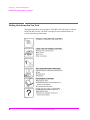
Materials Included in This Package
This package contains the following materials. Verify that all the materials are
present and inspect them for damage. If a part is missing or appears to be
damaged, contact your nearest Hewlett-Packard sales or service office.
•
HP 11807A Option 001 Test Software (part number 11807-10001) or HP 11807E
Option 001 Test Software (part number 11807-10020)
•
SRAM memory card (uninitialized), for saving your own test procedures and results.
•
For 11807A, 32 Kbyte SRAM (part number 85700A).
•
For 11807E, 64 Kbyte SRAM (part number 83230A).
•
HP 11807A,E Option 001 Software Reference Guide (part number 11807-90116)
•
HP software product license agreement
Additional Equipment Required
•
HP 8920A (B or D) RF Communications Test Set
•
16
HP 8920A Option 005: 512 Kbyte RAM Memory extension
S:\hp11807a\OPT001\USRGUIDE\BOOK\chapters\product.fb
Chapter 1, Product Description
HP 11807A,E Software
Recommended Equipment
•
HP 8920 Option 001: High-Stability Timebase
•
HP 8920 Option 004: Tone/Digital Signaling
•
HP 8920A Option 010: 400 Hz High-Pass Filter
•
HP 8920A Option 013: C MESSAGE Weighting Filter
•
External power supply An external power supply for the FM radio can be configured to
the HP 8920A in one of three ways:
1. A power supply or battery can be connected directly to the FM radio.
2. A power supply can be connected to the rear-panel DC CURRENT MEASUREMENT
banana-plug connectors. (This requires the HP 8920A Option 003, HP-IB/RS-232/
Current Measurement.)
3. A power supply can be controlled by the HP 8920A when it’s connected to the HPIB connector. (This requires the HP 8920A Option 003, HP-IB/RS-232/DC Current
Measurement.)
HP-IB programmable power supplies from the following series are supported for
external control:
HP 664xA
HP 665xA
HP 667xA
HP 668xA
NOTE:
HP 662xA and HP 663xA series DC power supplies are not supported.
S:\hp11807a\OPT001\USRGUIDE\BOOK\chapters\product.fb
17
Chapter 1, Product Description
HP 11807A,E Software
Ordering Upgrades
If your test set does not contain all of the required options you must update your
instrument accordingly. Order the necessary upgrade kit(s) from your local
Hewlett-Packard sales office. Regional sales offices are listed at the front of this
manual.
Required Upgrades
•
HP 8920A Option R05: 512 Kbyte RAM expansion retrofit kit
Recommended Upgrades
•
HP 8920A,B Option R01: High-Stability Timebase retrofit kit
•
HP 8920A,B Option R04: Tone/Digital Signaling retrofit kit
•
HP 8920A,B Option R10: 400 Hz High-Pass Filter (HPF) retrofit kit (A maximum of
two optional filters can be installed in your test set. If you already have two optional
filters installed, one of them must be removed before installing this kit.)
•
HP 8920A,B Option R13: C MESSAGE Weighting Filter retrofit kit (A maximum of
two optional filters can be installed in your test set. If you already have two optional
filters installed, one of them must be removed before installing this kit.)
Available Tests:
The following tests can be performed with this software.
18
•
TX and RX stand-by current drain
•
TX frequency error
•
TX output power
•
TX modulation limiting
•
TX audio frequency response
•
TX audio distortion
•
TX microphone sensitivity
•
TX FM hum and noise
•
TX residual AM hum and noise
•
TX CTCSS/CDCSS deviation, freq/code
•
RX hum and noise
•
RX audio distortion
•
RX frequency response
S:\hp11807a\OPT001\USRGUIDE\BOOK\chapters\product.fb
Chapter 1, Product Description
HP 11807A,E Software
•
RX usable sensitivity
•
RX audio squelch sensitivity
•
RX squelch blocking
•
RX CTCSS/CDCSS opening
•
RX audio sensitivity
•
RX variation of sensitivity with frequency
•
RX quick test
•
TX quick test
For test, parameter, and specification descriptions, see chapter 4, "Test,
Parameter, and Pass/Fail Limit Descriptions" on page 89.
Software Features
The following features simplify testing:
•
While adjustments are being made, a large meter display and auditory feedback are
provided.
•
Results of tests and pass/fail indications are displayed on the test set’s CRT, and can be
printed, or collected in a disk drive, memory card, PC, or HP palmtop computer.
•
The software allows the operator to change the order of tests, pass/fail limits, test
parameters, and equipment configurations.
S:\hp11807a\OPT001\USRGUIDE\BOOK\chapters\product.fb
19
Chapter 1, Product Description
Finding the Information You Need
Finding the Information You Need
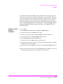
This manual describes the setup and use of the HP 11807A,E Software with the
HP 8920A,B,D Test Set. The book is arranged in self-contained chapters to
provide the following information:
4
5
6
20
S:\hp11807a\OPT001\USRGUIDE\BOOK\chapters\product.fb
Chapter 1, Product Description
Additional Services Available
Additional Services Available
Consult the HP 8920 User’s Guide or call the HP 8920 Hotline 1-800-922-8920
(in the USA and Canada only) and give your software model number.
S:\hp11807a\OPT001\USRGUIDE\BOOK\chapters\product.fb
21
Chapter 1, Product Description
Additional Services Available
22
S:\hp11807a\OPT001\USRGUIDE\BOOK\chapters\product.fb
2
Using the Software/HP 8920B or HP
8920A FW Above Rev. A.14.00
Chapter 2
Using the Software Above FW
Rev. A.14.00
23
Chapter 2, Using the Software/HP 8920B or HP 8920A FW Above Rev. A.14.00
NOTE:
The firmware revision A.14.00 in the HP 8920A,D had several enhancements, which are
standard in the HP 8920B. This chapter applies to users with:
•
HP 8920A test sets with firmware revision above A.14.00
•
All HP 8920B test sets.
The test set’s firmware revision is displayed on the top right corner of the
configuration screen.
•
Press SHIFT CONFIG to display the configuration screen and read the firmware
revision.
If you have an HP 8920A test set with firmware revision below A.14.00, refer to
chapter 3, "Using the Software/HP 8920A FW Rev. Below A.14.00," on page
57. Contact Hewlett-Packard at 1-800-922-8920 for details on upgrading your
firmware if desired.
24
S:\hp11807a\OPT001\USRGUIDE\BOOK\chapters\softav14.fb
Chapter 2, Using the Software/HP 8920B or HP 8920A FW Above Rev. A.14.00
The software can be run on the factory default settings or customized to your
individual needs and specific requirements. This chapter provides detailed
information on how to load, run, and customize the software.
The test set has two methods of accessing on-line help. In each of the screens in
the test environment, k4 (Help) accesses specific information about how to set
up/use the current screen. SHIFT HELP accesses the master help file, with an
alphabetical listing of help topics.
25
S:\hp11807a\OPT001\USRGUIDE\BOOK\chapters\softav14.fb
Chapter 2, Using the Software/HP 8920B or HP 8920A FW Above Rev. A.14.00
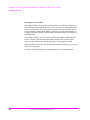
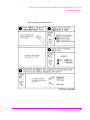
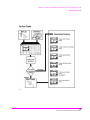
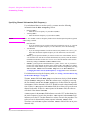
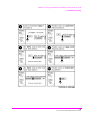
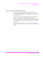
Testing Overview
Testing Overview
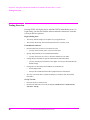
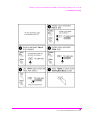
Pressing TESTS will display what is called the TESTS (Main Menu) screen. To
begin testing, you must first load the software and make connections. From this
screen you have the option to:
Begin running tests:
•
The factory default settings are acceptable for your application or
•
The software has already been customized and saved to a memory card
Customize the software:
•
Decide which tests you desire to run (Order of Tests)
•
•
Specify which channels to test (Channel Information)
•
•
•
you may want to test one, some, or all of the channels on your radio.
Change the pass/fail limits for specific measurements (Pass/Fail Limits)
•
•
you may want to run all, some, or just one of the tests.
you may want the pass/fail limits to have tighter or looser specifications than the
default settings.
Change the test environment and conditions (Test Parameters)
•
decide output format.
•
enter specific information about radio equipment and/or environment.
Save any or all of the above customized changes to a memory card (Save/Delete
Procedure)
Set Up Test Set:
26
•
Print test results or certain screens.
•
Decide when and where test results are displayed (Execution Conditions/
Printer Setup)
S:\hp11807a\OPT001\USRGUIDE\BOOK\chapters\softav14.fb
Chapter 2, Using the Software/HP 8920B or HP 8920A FW Above Rev. A.14.00
Testing Overview
5
27
S:\hp11807a\OPT001\USRGUIDE\BOOK\chapters\softav14.fb
Chapter 2, Using the Software/HP 8920B or HP 8920A FW Above Rev. A.14.00
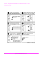
Testing Overview
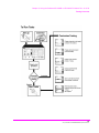
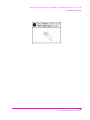
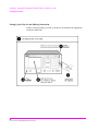
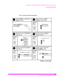
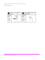
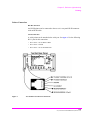
Setting Up the Test Set and Making Connections
Before you begin testing, you must set up the test set and make the appropriate
hardware connections.
28
S:\hp11807a\OPT001\USRGUIDE\BOOK\chapters\softav14.fb
Chapter 2, Using the Software/HP 8920B or HP 8920A FW Above Rev. A.14.00
Testing Overview
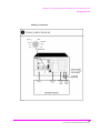
Making a Connection
29
S:\hp11807a\OPT001\USRGUIDE\BOOK\chapters\softav14.fb
Chapter 2, Using the Software/HP 8920B or HP 8920A FW Above Rev. A.14.00
Testing Overview
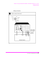
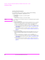
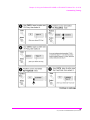
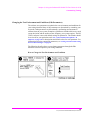
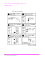
Selecting a Test Procedure
To load the software, you must first select the location to load from (in this case, it
will be Card) and a procedure filename. Your card comes pre-programmed with
at least one procedure. The actual software program does not get loaded into the
test set’s memory until k1 (Run Test) is selected. It will take approximately 15
seconds to load the software in an HP 8920B, and approximately two minutes in
an HP 8920A,D.
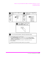
The software memory card can be removed after the program is loaded into the
test set’s memory. The program will remain in memory after a power-down/
power-up cycle, unless it is manually deleted or a new program is loaded.
When tests begin to run, they are executed in the order in which they were entered
into the Test Procedure.
Pressing CANCEL will pause the current test (press k2 to continue the test.)
30
S:\hp11807a\OPT001\USRGUIDE\BOOK\chapters\softav14.fb
Chapter 2, Using the Software/HP 8920B or HP 8920A FW Above Rev. A.14.00
Testing Overview
Selecting A Test Procedure
31
S:\hp11807a\OPT001\USRGUIDE\BOOK\chapters\softav14.fb
Chapter 2, Using the Software/HP 8920B or HP 8920A FW Above Rev. A.14.00
Customizing Testing
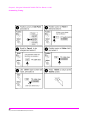
Customizing Testing
Because of the diversity of individual testing needs, the software has been
designed so that changes may be easily made from the test set’s front panel. You
may store these changes on a memory card so that you may skip these steps in the
future. See "Saving a Test Procedure" on page 50.
Because your needs change, the software allows changes to its default settings
whenever you need to make them. For example, tests may be inserted or deleted,
and later after running the tests you can change the pass/fail limits or decide to test
different channels.
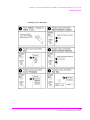
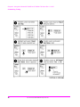
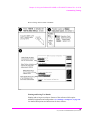
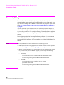
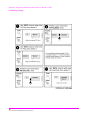
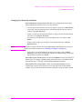
Most testing customization is accomplished through the customization screens.
These customization screens are accessed from the main TESTS (Main Menu)
screen as shown in the following figure. Customizing procedures is explained
later in this chapter.
NOTE:
External Devices, Printer Setup, and IBASIC will not be explained in this customizing
section.
•
External Devices and Printer Setup are used when setting up printers and external disk
drives which is explained in "Disks" on page 198 and "Printing" on page 212 in
chapter 5.
•
IBASIC is used when writing your own programs and is not explained in this manual.
If you need to write your own IBASIC programs you may acquire the following
manuals:
•
•
32
8920A,D
•
HP Instrument Basic User’s Handbook HP part number E2083-90000.
•
HP 8920A Programming Manual HP part number 08920-90220.
8920B
•
HP Instrument Basic User’s Handbook Version 2.0
HP part number E2083-90005.
•
HP 8920B Programming Manual HP part number 08920-90222.
S:\hp11807a\OPT001\USRGUIDE\BOOK\chapters\softav14.fb
Chapter 2, Using the Software/HP 8920B or HP 8920A FW Above Rev. A.14.00
Customizing Testing
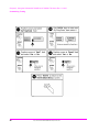
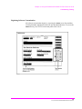
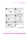
How to Customize Testing
33
S:\hp11807a\OPT001\USRGUIDE\BOOK\chapters\softav14.fb
Chapter 2, Using the Software/HP 8920B or HP 8920A FW Above Rev. A.14.00
Customizing Testing
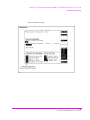
Changing the Order of Tests
You may define the order of tests to include all, some, or just one of the tests
available. When the first test is finished, the next will run. The test sequence will
remain in the test set’s battery backed-up memory until another test sequence is
loaded or set up. For information on saving a customized test sequence, see
"Saving a Test Procedure" on page 50.
Defining the order of tests is accomplished by inserting or deleting tests from the
list of tests that come with the software package. See chapter 4, "Test, Parameter,
and Pass/Fail Limit Descriptions" on page 89, for descriptions of tests included in
this package.
The All Chans? field allows the user to decide to run the test on all channels
entered in the Channel Information table, or just the channels which are
selected as Prime in the Channel Information screen. This feature allows the
user the flexibility to use channels that are selected as Prime in all the tests in the
sequence, and those indicated as non-prime in a subset of tests (those tests with a
Yes response in All Chans). For more information, see "Specifying Channel
Information" on page 38.
The following describes how to create a new test sequence and enter a response to
the All Chans? field.
34
S:\hp11807a\OPT001\USRGUIDE\BOOK\chapters\softav14.fb
Chapter 2, Using the Software/HP 8920B or HP 8920A FW Above Rev. A.14.00
Customizing Testing
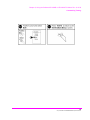
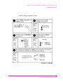
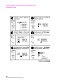
How to Change the Order of Tests
35
S:\hp11807a\OPT001\USRGUIDE\BOOK\chapters\softav14.fb
Chapter 2, Using the Software/HP 8920B or HP 8920A FW Above Rev. A.14.00
Customizing Testing
36
S:\hp11807a\OPT001\USRGUIDE\BOOK\chapters\softav14.fb
Chapter 2, Using the Software/HP 8920B or HP 8920A FW Above Rev. A.14.00
Customizing Testing
37
S:\hp11807a\OPT001\USRGUIDE\BOOK\chapters\softav14.fb
Chapter 2, Using the Software/HP 8920B or HP 8920A FW Above Rev. A.14.00
Customizing Testing
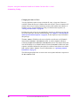
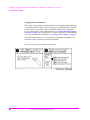
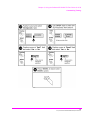
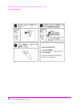
Specifying Channel Information
For each channel that you wish to specify, you must enter the following
information into the Channel Information screen:
•
•
NOTE:
Enter a −1 in the RX or TX test frequency fields to have all subsequent frequencies ignored
when testing is started.
•
•
38
RX Freq (MHz)
• Enter the receive frequency of your radio in (MHz).
TX Freq (MHz)
• Enter the transmit frequency of your radio in (MHz).
Sq Freq/Code (for RX Freq)
• If you are testing receiver CTCSS or CDCSS (test parameter 8 is set=1), you must
enter the receive squelch frequency or code. Otherwise, leave this field empty.
1. Enter a CTCSS frequency, for example, 91.5 Hz as “CT FR91.5”, or
2. Enter a CTCSS tone code, for example, “ZZ” for 91.5 Hz as “CT ZZ”. The tone
codes supported by the software are shown in table 17, "CTCSS Tone Codes"
on page 248, or
3. Enter a CDCSS code word, for example “CD 023” (octal). The code words
supported by the software are shown in table 18, "CDCSS Code Words" on
page 249.
Sq Freq/Code (for TX Freq)
• If you are testing transmitter CTCSS or CDCSS (test parameter 23 is set=1), you
must enter the transmit squelch frequency or code. Otherwise, leave this field
empty.
1. Enter a CTCSS frequency, for example, 91.5 Hz as “CT FR91.5”, or
1. Enter a CTCSS tone code, for example, “ZZ” for 91.5 Hz as “CT ZZ”. The tone
codes supported by the software are shown in table 17, "CTCSS Tone Codes"
on page 248, or
2. Enter a CDCSS code word, for example “CD 023” (octal). The code words
supported by the software are shown in table 18, "CDCSS Code Words" on
page 249.
S:\hp11807a\OPT001\USRGUIDE\BOOK\chapters\softav14.fb
Chapter 2, Using the Software/HP 8920B or HP 8920A FW Above Rev. A.14.00
Customizing Testing
•
•
Test? (yes/no) specifies whether you want to test the UUT at this channel. If set to
“No” then the UUT will not be tested at that channel, but you may retain the channel
information in the table for later use. If set to “Yes” then the channel will be used as
defined by settings of Prime? and All Chans? fields.
Prime? (yes/no) specifies which channels are “prime”. Select “Yes” if you want to
test the UUT at this channel on all the tests in the procedure. Select No if you want to
test the UUT at this channel on just a subset of tests, which are designated by selecting
Yes in the All Chans field of the Order of Tests screen. See All Chans?
in "Changing the Order of Tests" on page 34 for more information.
For information on saving the channel information table, see "Saving a Test
Procedure" on page 50.
The All Chans field in the Order of Tests screen interacts closely with the
Prime? field on the Channel Information screen. When the software runs, it
begins by retrieving the first channel entered into the Channel Information
screen. It then checks the response in the Test? field to determine if the UUT
should be tested at that channel at this time. If there is a No response in the Test?
field, the software will go to the next channel in the table. If there is a Yes
response in the Test? field, the software will check if the channel is Prime.
A Yes response in the Prime? field indicates to test the UUT at that channel on
the entire sequence of tests in the procedure. A No response in the Prime? field
indicates to test the UUT at that channel on a subset of tests in the procedure. The
subset of tests is determined by a Yes response in the All Chans? field.
Therefore, tests with a No response in the All Chans? field will be run on prime
channels only.
39
S:\hp11807a\OPT001\USRGUIDE\BOOK\chapters\softav14.fb
Chapter 2, Using the Software/HP 8920B or HP 8920A FW Above Rev. A.14.00
Customizing Testing
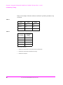
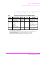
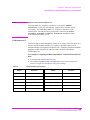
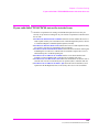
Below is an example of how the software would run if you had a procedure set up
as follows:
Table 1
Chan #
Test?
Prime?
Chan 01
Yes
Yes
Chan 02
Yes
No
Chan 03
No
No
Table 2
Test Number
All Chan?
Setting
Test 01
No
Test 02
Yes
Test 03
Yes
Test 04
No
The result would be:
40
•
Chan 01 is used in Test 01, Test 02, Test 03, and Test 04.
•
Chan 02 is used in Test 02, and Test 03 only.
•
Chan 03 is not used.
S:\hp11807a\OPT001\USRGUIDE\BOOK\chapters\softav14.fb
Chapter 2, Using the Software/HP 8920B or HP 8920A FW Above Rev. A.14.00
Customizing Testing
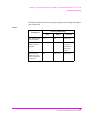
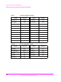
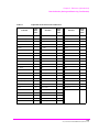
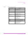
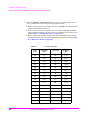
The following table 3 shows how to properly configure these settings according to
your testing needs.
Table 3
Necessary Field Settings
Testing Need
Test?
Prime?
All Chan?
Test channel on all
tests in sequence
Yes
Yes
Don’t Care
Test channel on a
subset of tests in
sequence
Yes
No
Yes on tests
you want
included in
the testing
subset
Do not test this
channel now, but
retain information
for later use
No
Don’t Care
Don’t Care
41
S:\hp11807a\OPT001\USRGUIDE\BOOK\chapters\softav14.fb
Chapter 2, Using the Software/HP 8920B or HP 8920A FW Above Rev. A.14.00
Customizing Testing
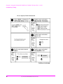
How to Specify Channel Information
42
S:\hp11807a\OPT001\USRGUIDE\BOOK\chapters\softav14.fb
Chapter 2, Using the Software/HP 8920B or HP 8920A FW Above Rev. A.14.00
Customizing Testing
43
S:\hp11807a\OPT001\USRGUIDE\BOOK\chapters\softav14.fb
Chapter 2, Using the Software/HP 8920B or HP 8920A FW Above Rev. A.14.00
Customizing Testing
44
S:\hp11807a\OPT001\USRGUIDE\BOOK\chapters\softav14.fb
Chapter 2, Using the Software/HP 8920B or HP 8920A FW Above Rev. A.14.00
Customizing Testing
Changing Pass/Fail Limits
Pass/Fail limits define the values a measurement’s result is compared against to
determine if the UUT meets its specified standards. Default values are set in the
test software. These default values may be changed to suit your particular
requirements.
The following describes how to change the pass/fail (upper and lower) limits. See
"Pass/Fail Limit Descriptions (specifications)," in chapter 4, on page 144 for
descriptions of each pass/fail limit. For information on saving customized pass/
fail limits, see "Saving a Test Procedure" on page 50.
How to Change Pass/Fail Limits
45
S:\hp11807a\OPT001\USRGUIDE\BOOK\chapters\softav14.fb
Chapter 2, Using the Software/HP 8920B or HP 8920A FW Above Rev. A.14.00
Customizing Testing
46
S:\hp11807a\OPT001\USRGUIDE\BOOK\chapters\softav14.fb
Chapter 2, Using the Software/HP 8920B or HP 8920A FW Above Rev. A.14.00
Customizing Testing
47
S:\hp11807a\OPT001\USRGUIDE\BOOK\chapters\softav14.fb
Chapter 2, Using the Software/HP 8920B or HP 8920A FW Above Rev. A.14.00
Customizing Testing
Changing the Test Parameters
The software uses parameters to optimize the test environment and conditions for
your testing situation. Many of the test parameters are determined by examining
your test needs. The software comes with default settings for test parameters.
Review the defaults for your particular needs. See "Test Parameter Descriptions,"
in chapter 4, on page 112 for descriptions of each test parameter. For information
on saving customized test parameters, see "Saving a Test Procedure" on page 50.
The following describes how you can change test parameters through the Test
Parameter screen to optimize your testing conditions.
How to Change the Test Environment and Conditions
48
S:\hp11807a\OPT001\USRGUIDE\BOOK\chapters\softav14.fb
Chapter 2, Using the Software/HP 8920B or HP 8920A FW Above Rev. A.14.00
Customizing Testing
49
S:\hp11807a\OPT001\USRGUIDE\BOOK\chapters\softav14.fb
Chapter 2, Using the Software/HP 8920B or HP 8920A FW Above Rev. A.14.00
Customizing Testing
Saving a Test Procedure
A Test Procedure is a collection of channel information, test parameters, testing
order, and pass/fail limits saved in a file that customizes the test software to a
specific application. You may save the file to a memory card or disk.
When you save a procedure you will be saving channel information, test
parameters, pass/fail limits, and testing order, plus a library that contains the
names of all test parameters, pass/fail limits, and tests that are resident in the
software. The library file comes from the software and cannot be modified. The
library file will be automatically saved on the card or disk that is being used to
store the new test procedure.
The following example shows how to save a new procedure to a memory card.
For more information concerning procedures, see "Procedures," in chapter 5, on
page 225.
50
S:\hp11807a\OPT001\USRGUIDE\BOOK\chapters\softav14.fb
Chapter 2, Using the Software/HP 8920B or HP 8920A FW Above Rev. A.14.00
Customizing Testing
How to Save a Test Procedure
5
5
51
S:\hp11807a\OPT001\USRGUIDE\BOOK\chapters\softav14.fb
Chapter 2, Using the Software/HP 8920B or HP 8920A FW Above Rev. A.14.00
Customizing Testing
52
S:\hp11807a\OPT001\USRGUIDE\BOOK\chapters\softav14.fb
Chapter 2, Using the Software/HP 8920B or HP 8920A FW Above Rev. A.14.00
Customizing Testing
53
S:\hp11807a\OPT001\USRGUIDE\BOOK\chapters\softav14.fb
Chapter 2, Using the Software/HP 8920B or HP 8920A FW Above Rev. A.14.00
Customizing Testing
Changing Test Execution Conditions
Test Execution Conditions define where and when test output occurs. You
may decide to:
•
NOTE:
Display output on CRT only, or display on CRT and print hardcopy (Output
Results To).
If printing test results is desired, after selecting Printer, additional steps are necessary to
connect and configure the printer. See "Printing," in chapter 5, on page 212.
•
Display (or print) only measurements that fail, or display (or print) all measurements
that pass or fail (Output Results For).
•
Enter a title for an output heading for the displayed or printed results (Output
Heading).
•
Stop testing when a measurement fails or continue through all of the tests without
stopping (If Unit-Under-Test-Fails).
•
Pause between each measurement, or run through entire test (Test Procedure
Run Mode).
•
Start the program automatically when the Test System is powered on. (Autostart
Test Procedure on Power-up)
Test Execution Conditions is accessed from the SETUP TEST SET: list.
To change a default setting, position the cursor to the desired field. Pressing the
knob (”selecting”) will toggle the underlined selection.
Test Execution Conditions settings are not retained after a power-down/
power-up cycle, and will return to their default settings.
54
S:\hp11807a\OPT001\USRGUIDE\BOOK\chapters\softav14.fb
Chapter 2, Using the Software/HP 8920B or HP 8920A FW Above Rev. A.14.00
Customizing Testing
How to Change Test Execution Conditions
Printing and Saving Test Results
Printing and saving test results are features of the software which require
additional equipment and configuration. See "Printing," in chapter 5, on page 212
for detailed descriptions and instructions for these features.
55
S:\hp11807a\OPT001\USRGUIDE\BOOK\chapters\softav14.fb
Chapter 2, Using the Software/HP 8920B or HP 8920A FW Above Rev. A.14.00
Customizing Testing
56
S:\hp11807a\OPT001\USRGUIDE\BOOK\chapters\softav14.fb
3
Using the Software/HP 8920A FW Rev.
Below A.14.00
Chapter 3
Using the Software Below FW
Rev. A.14.00
57
Chapter 3, Using the Software/HP 8920A FW Rev. Below A.14.00
NOTE:
The firmware revision A.14.00 in the HP 8920A,D had several enhancements, which are
standard in the HP 8920B. This chapter applies to users with:
•
HP 8920A test sets with firmware revision below A.14.00
The test set’s firmware revision is displayed on the top right corner of the
configuration screen.
•
Press SHIFT CONFIG to display the configuration screen and read the firmware
revision.
If you have an HP 8920B or an HP 8920A with firmware revision above A.14.00,
refer to chapter 2, "Using the Software/HP 8920B or HP 8920A FW Above
Rev. A.14.00," on page 23. Contact Hewlett-Packard at 1-800-922-8920 for
details on upgrading your firmware if desired.
58
S:\hp11807a\OPT001\USRGUIDE\BOOK\chapters\softbw14.fb
Chapter 3, Using the Software/HP 8920A FW Rev. Below A.14.00
The HP 11807A software can be run on the factory default settings or customized
to your individual needs and the specific requirements. This chapter provides
detailed information on how to load, run, and customize the software.
59
S:\hp11807a\OPT001\USRGUIDE\BOOK\chapters\softbw14.fb
Chapter 3, Using the Software/HP 8920A FW Rev. Below A.14.00
Testing Overview
Testing Overview
Pressing TESTS will display what is called the TESTS screen. To begin testing,
you must first load the software and make connections. From this screen you have
the option to:
Begin running tests:
•
The factory default settings are acceptable for your application or
•
The software has already been customized and saved to a memory card
Customize the software:
•
Decide which tests you desire to run (Edit Seqn)
•
•
Specify which channels to test (Edit Freq)
•
•
•
you may want to test one, some, or all of the channels on your radio.
Change the pass/fail limits for specific measurements (Edit Spec)
•
•
you may want to run all, some, or just one of the tests.
you may want the pass/fail limits to have tighter or looser specifications than the
default settings.
Change the test environment and conditions (Edit Parm)
•
decide output format.
•
enter specific information about radio equipment and/or environment.
Save any or all of the above customized changes to a memory card (Proc Mngr)
Set Up Test Set:
•
Print test results or certain screens.
•
Decide when and where test results are displayed (Edit Cnfg)
60
S:\hp11807a\OPT001\USRGUIDE\BOOK\chapters\softbw14.fb
Chapter 3, Using the Software/HP 8920A FW Rev. Below A.14.00
Testing Overview
5
61
S:\hp11807a\OPT001\USRGUIDE\BOOK\chapters\softbw14.fb
Chapter 3, Using the Software/HP 8920A FW Rev. Below A.14.00
Testing Overview
Setting Up the Test Set and Making Connections
Before you begin testing, you must set up the test set and make the appropriate
hardware connections.
62
S:\hp11807a\OPT001\USRGUIDE\BOOK\chapters\softbw14.fb
Chapter 3, Using the Software/HP 8920A FW Rev. Below A.14.00
Testing Overview
Making a Connection
63
S:\hp11807a\OPT001\USRGUIDE\BOOK\chapters\softbw14.fb
Chapter 3, Using the Software/HP 8920A FW Rev. Below A.14.00
Testing Overview
Selecting a Test Procedure
To load the software, you must first select the location to load from (in this case, it
will be Card) and a procedure filename. Your card comes pre-programmed with
at least one procedure. The actual software program does not get loaded into the
test set’s memory until k1 (Run Test) is selected. It will take approximately 2
minutes to load the software in an HP 8920A,D.
The software memory card can be removed after the program is loaded into the
test set’s memory. The program will remain in memory after a power-down/
power-up cycle, unless it is manually deleted or a new program is loaded.
When tests begin to run, they are executed in the order in which they were entered
into the Test Procedure.
Pressing CANCEL will pause the current test (press k2 to continue the test.)
64
S:\hp11807a\OPT001\USRGUIDE\BOOK\chapters\softbw14.fb
Chapter 3, Using the Software/HP 8920A FW Rev. Below A.14.00
Testing Overview
Selecting A Test Procedure
65
S:\hp11807a\OPT001\USRGUIDE\BOOK\chapters\softbw14.fb
Chapter 3, Using the Software/HP 8920A FW Rev. Below A.14.00
Customizing Testing
Customizing Testing
Because of the diversity of individual testing needs, the software has been
designed so that changes may be easily made from the test set’s front panel. You
may store these changes on an SRAM card so that you may skip these steps in the
future. See "Saving a Test Procedure Using the Procedure Manager," in chapter 3,
on page 83.
You may customize your software at any time. Because your needs change, the
software allows changes to its default settings when you need to make them and in
any order that you choose. For example, tests may be inserted or deleted, and later
after running the tests you can change the pass/fail limits or decide to test different
channels.
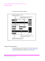
Most testing customization is accomplished through the test set’s Test Function
screens. These Test Function screens are accessed from the main TESTS screen as
shown in the following figure. All Test Functions are explained in this chapter by
function.
NOTE:
Edit Cnfg and IBASIC will not be explained in this customizing section.
•
Edit Cnfg is used when setting up printers and external disk drives which is explained
in "Disks" on page 198and "Printing" on page 212 in chapter 5.
•
IBASIC is used when writing your own programs and is not explained in this manual.
If you need to write your own IBASIC programs you may acquire the following
manuals:
•
•
HP 8920A,D
•
HP Instrument Basic User’s Handbook HP part number E2083-90000.
•
HP 8920A Programming Manual HP part number 08920-90220.
HP 8920B
•
HP Instrument Basic User’s Handbook Version 2.0 HP
part number E2083-90005.
•
HP 8920B Programming Manual HP part number 08920-90222.
66
S:\hp11807a\OPT001\USRGUIDE\BOOK\chapters\softbw14.fb
Chapter 3, Using the Software/HP 8920A FW Rev. Below A.14.00
Customizing Testing
Beginning Software Customization
All software customization begins by accessing the TESTS screen first and then
selecting the Test Function which will open the Choices menu. To access the
TESTS screen, press TESTS on the front panel of the test set.
67
S:\hp11807a\OPT001\USRGUIDE\BOOK\chapters\softbw14.fb
Chapter 3, Using the Software/HP 8920A FW Rev. Below A.14.00
Customizing Testing
Changing the Order of Tests (Edit Sequence)
You may define a test sequence to include all, some, or just one of the tests
available. When the first test is finished, the next will run. The test sequence will
remain in the Test System’s battery backed-up memory until another test
sequence is loaded or set up. For information on saving a customized test
sequence, see "Changing the Order of Tests (Edit Sequence)" on page 68.
Creation of a test sequence is accomplished by inserting or deleting tests from the
list of tests that come with the HP 11807A software package. See chapter 4, "Test,
Parameter, and Pass/Fail Limit Descriptions" on page 89, for test descriptions.
The All Chans? field allows the user to decide to run the test on all channels
entered in the frequency table, or just the channels which are selected as Prime in
the Edit Freq screen. This feature allows the user the flexibility to use channels
that are selected as Prime in all the tests in the sequence, and those selected as
non-prime in a subset of tests (those with a Yes response in All Chans). For
more information, see "Specifying Channel Information (Edit Frequency)" on page
72.
The following describes how to create a new test sequence and enter a response to
All Chans.
68
S:\hp11807a\OPT001\USRGUIDE\BOOK\chapters\softbw14.fb
Chapter 3, Using the Software/HP 8920A FW Rev. Below A.14.00
Customizing Testing
How to Change a Sequence of Tests
69
S:\hp11807a\OPT001\USRGUIDE\BOOK\chapters\softbw14.fb
Chapter 3, Using the Software/HP 8920A FW Rev. Below A.14.00
Customizing Testing
70
S:\hp11807a\OPT001\USRGUIDE\BOOK\chapters\softbw14.fb
Chapter 3, Using the Software/HP 8920A FW Rev. Below A.14.00
Customizing Testing
71
S:\hp11807a\OPT001\USRGUIDE\BOOK\chapters\softbw14.fb
Chapter 3, Using the Software/HP 8920A FW Rev. Below A.14.00
Customizing Testing
Specifying Channel Information (Edit Frequency)
For each channel that you wish to specify, you must enter the following
information into the Edit Frequency screen:
•
•
NOTE:
RX Freq (MHz)
• Enter the receive frequency of your radio in (MHz).
TX Freq (MHz)
• Enter the transmit frequency of your radio in (MHz).
Enter a −1 in the RX or TX test frequency fields to have all subsequent frequencies ignored
when testing is started.
•
•
•
•
RX Chan Info
• If you are testing receiver CTCSS or CDCSS (test parameter 8 is set=1), you must
enter the receive squelch frequency or code. Otherwise, leave this field empty.
TX Chan Info
• If you are testing transmitter CTCSS or CDCSS (test parameter 23 is set=1), you
must enter the transmit squelch frequency or code. Otherwise, leave this field
empty.
Test? (yes/no) specifies whether you want to test the UUT at this channel. If set to
“No” then the UUT will not be tested at that channel, but you may retain the channel
information in the table for later use. If set to “Yes” then the channel will be used as
defined by settings of Prime? and All Chans? fields.
Prime? (yes/no) specifies which channels are “prime”. Select “Yes” if you want to
test the UUT at this channel on all the tests in the procedure. Select No if you want to
test the UUT at this channel on just a subset of tests, which are designated by selecting
Yes in the All Chans field of the Edit Seqn screen. See All Chans? in
"Changing the Order of Tests (Edit Sequence)" on page 68 for more information.
For information on saving the frequency table, see "Saving a Test Procedure Using
the Procedure Manager" on page 83.
The All Chans field in the Edit Seqn screen interacts closely with the Prime?
field on the Edit Freq screen. When the software runs, it begins by retrieving
the first channel entered into the Edit Freq screen. It then checks the response
in the Test? field to determine if the UUT should be tested at that channel at this
time. If there is a No response in the Test? field, the software will go to the next
channel in the table. If there is a Yes response in the Test? field, the software
will check if the channel is Prime.
A Yes response in the Prime? field indicates to test the UUT at that channel on
the entire sequence of tests in the procedure. A No response in the Prime? field
indicates to test the UUT at that channel on a subset of tests in the procedure. The
subset of tests is determined by a Yes response in the All Chans? field.
Therefore, tests with a No response in the All Chans? field will be run on prime
channels only.
72
S:\hp11807a\OPT001\USRGUIDE\BOOK\chapters\softbw14.fb
Chapter 3, Using the Software/HP 8920A FW Rev. Below A.14.00
Customizing Testing
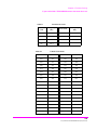
Below is an example of how the software would run if you had a procedure set up
as follows:
Table 4
Chan #
Test?
Prime?
Chan 01
Yes
Yes
Chan 02
Yes
No
Chan 03
No
No
Table 5
Test Number
All Chan?
Setting
Test 01
No
Test 02
Yes
Test 03
Yes
Test 04
No
The result would be:
•
Chan 01 is used in Test 01, Test 02, Test 03, and Test 04.
•
Chan 02 is used in 02, and Test 03 only.
•
Chan 03 is not used.
73
S:\hp11807a\OPT001\USRGUIDE\BOOK\chapters\softbw14.fb
Chapter 3, Using the Software/HP 8920A FW Rev. Below A.14.00
Customizing Testing
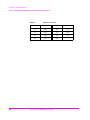
The following table shows how to properly configure these settings according to
your testing needs.
Table 6
Necessary Field Settings
Testing Need
Test?
Prime?
All Chan?
Test channel
on all tests in
sequence
Yes
Yes
Don’t Care
Test channel
on a subset of
tests in
sequence
Yes
No
Yes on tests
you want
included in
the testing
subset
Do not test
this channel
now, but retain
information
for later use
No
Don’t Care
Don’t Care
74
S:\hp11807a\OPT001\USRGUIDE\BOOK\chapters\softbw14.fb
Chapter 3, Using the Software/HP 8920A FW Rev. Below A.14.00
Customizing Testing
How to Specify Channel Information
75
S:\hp11807a\OPT001\USRGUIDE\BOOK\chapters\softbw14.fb
Chapter 3, Using the Software/HP 8920A FW Rev. Below A.14.00
Customizing Testing
76
S:\hp11807a\OPT001\USRGUIDE\BOOK\chapters\softbw14.fb
Chapter 3, Using the Software/HP 8920A FW Rev. Below A.14.00
Customizing Testing
77
S:\hp11807a\OPT001\USRGUIDE\BOOK\chapters\softbw14.fb
Chapter 3, Using the Software/HP 8920A FW Rev. Below A.14.00
Customizing Testing
Changing Pass/Fail Limits (Edit Specifications)
Specifications are values that set pass/fail limits for tests. Default values are
available in the test software. These default values may be changed to suit your
particular requirements.
The following describes how to change the pass/fail (upper and lower) limits in
the HP 8920A,D Edit Specification screen. See "Pass/Fail Limit
Descriptions (specifications)," in chapter 4, on page 144 for descriptions for each
specification. For information on saving customized specifications, see "Saving a
Test Procedure Using the Procedure Manager" on page 83.
How to Change Pass/Fail Limits
78
S:\hp11807a\OPT001\USRGUIDE\BOOK\chapters\softbw14.fb
Chapter 3, Using the Software/HP 8920A FW Rev. Below A.14.00
Customizing Testing
79
S:\hp11807a\OPT001\USRGUIDE\BOOK\chapters\softbw14.fb
Chapter 3, Using the Software/HP 8920A FW Rev. Below A.14.00
Customizing Testing
80
S:\hp11807a\OPT001\USRGUIDE\BOOK\chapters\softbw14.fb
Chapter 3, Using the Software/HP 8920A FW Rev. Below A.14.00
Customizing Testing
Changing the Test Environment and Conditions (Edit Parameters)
The software uses parameters to optimize the test environment and conditions for
your testing situation. Many of the parameters are determined by examining your
test needs. Other parameters are determined by performing measurements to
calibrate items in your system. Examples of parameters include cable losses, rated
system deviation, and the audio test tone frequency your system requires. The HP
11807A software comes with default settings for parameters. The defaults should
be reviewed for your particular needs. See "Test Parameter Descriptions," in
chapter 4, on page 112 for descriptions and default values for each parameter. For
information on saving customized parameters, see "Saving a Test Procedure Using
the Procedure Manager" on page 83.
The following describes how you can change parameters through the Edit
Parameter screen to optimize your testing conditions.
How to Change the Test Environment and Conditions
81
S:\hp11807a\OPT001\USRGUIDE\BOOK\chapters\softbw14.fb
Chapter 3, Using the Software/HP 8920A FW Rev. Below A.14.00
Customizing Testing
82
S:\hp11807a\OPT001\USRGUIDE\BOOK\chapters\softbw14.fb
Chapter 3, Using the Software/HP 8920A FW Rev. Below A.14.00
Customizing Testing
Saving a Test Procedure Using the Procedure Manager
A Test Procedure is a collection of pass/fail limits (specifications), the test
environment and conditions (parameters), and a TEST sequence, saved in a file
that customizes the test software to a specific application. You may save the file to
a memory card or disk.
When you save a Procedure you will be saving parameters, specifications, and a
test sequence, plus a library that contains the names of all parameters,
specifications, and tests that are resident in the HP 11807A software. The library
file comes from the HP 11807A software and cannot be modified. The library file
will be automatically saved on the card or disk that is being used to store the new
test procedure.
The following example shows how to save a new procedure to a memory card.
For more information concerning procedures, see "Procedures," in chapter 5, on
page 225.
83
S:\hp11807a\OPT001\USRGUIDE\BOOK\chapters\softbw14.fb
Chapter 3, Using the Software/HP 8920A FW Rev. Below A.14.00
Customizing Testing
How to Save a Test Procedure
5
84
S:\hp11807a\OPT001\USRGUIDE\BOOK\chapters\softbw14.fb
Chapter 3, Using the Software/HP 8920A FW Rev. Below A.14.00
Customizing Testing
85
S:\hp11807a\OPT001\USRGUIDE\BOOK\chapters\softbw14.fb
Chapter 3, Using the Software/HP 8920A FW Rev. Below A.14.00
Customizing Testing
86
S:\hp11807a\OPT001\USRGUIDE\BOOK\chapters\softbw14.fb
Chapter 3, Using the Software/HP 8920A FW Rev. Below A.14.00
Customizing Testing
Changing Test Execution Conditions
Test Execution Conditions define how your testing program starts and
where and when test output occurs. You may decide to:
NOTE:
•
Start the program automatically when the Test System is powered on. (Autostart)
•
Stop testing when a measurement fails or continue through all of the tests without
stopping. (On UUT Failure)
•
Display (or print) only measurements that fail, or display (or print) all measurements
that pass or fail. (Output Results)
•
Pause between each measurement, or run through the entire test sequence. (Run
Mode)
•
Display output on CRT only, or display on CRT and print hardcopy. (Output
Destination)
If printing test results is desired, after selecting Printer additional steps are necessary to
connect and configure the printer. See "Printing," in chapter 5, on page 212.
•
Enter a title for an output heading for the displayed or printed results. (Output
Heading). Select the field with the knob and enter the output heading by selecting the
appropriate letters and the select Done.
Test Execution Conditions is located on the TESTS screen. Press TESTS to
display them. To change a default setting, position the cursor to the desired field.
Pressing the knob (”selecting”) will toggle the underlined selection.
Test Execution Conditions settings (except for Autostart) are not
retained after a power-down/ power-up cycle, and will return to their default
settings. They are not stored on the memory card when a test procedure is saved.
87
S:\hp11807a\OPT001\USRGUIDE\BOOK\chapters\softbw14.fb
Chapter 3, Using the Software/HP 8920A FW Rev. Below A.14.00
Customizing Testing
How to Change Test Execution Conditions
Printing and Saving Test Results
Printing and saving test results are features of the HP 11807A software which
require additional equipment and configuration. See "Printing," in chapter 5, on
page 212 for detailed descriptions and instructions for these features.
88
S:\hp11807a\OPT001\USRGUIDE\BOOK\chapters\softbw14.fb
4
Test, Parameter, and Pass/Fail Limit
Descriptions
Chapter 4
Test, Parameter, and Pass/Fail
Limit Descriptions
89
Chapter 4, Test, Parameter, and Pass/Fail Limit Descriptions
Introduction
Introduction
Tests are a series of measurements, and one or more tests make up a procedure
(see chapter 2, "Using the Software/HP 8920B or HP 8920A FW Above Rev.
A.14.00"). While you may change the tests that make up a procedure, you may not
change the measurements the test will perform. Generally, the order in which the
tests are run is not important.
This chapter describes each test and the associated test parameters, pass/fail
limits, and external equipment that are required. When you first load a test
procedure or create a new test sequence, refer to this section to understand what
test parameters and pass/fail limits are required for each test.
Tests are derived from the following industry standards:
•
EIA – Electronic Industry Association, FM test pass/fail limits,
EIA/TIA-603
EIA/TIA-204-D (TEST_19. RX Variation of Sens with Freq)
NOTE:
90
Refer to chapter 2 in this manual for details about customizing a Test Procedure for testing
your FM radio.
S:\hp11807a\OPT001\USRGUIDE\BOOK\chapters\descrptn.fb
Chapter 4, Test, Parameter, and Pass/Fail Limit Descriptions
TEST_01. TX and RX Stand-by Current Drain
TEST_01. TX and RX Stand-by Current Drain
This test measures the power-supply current required by the FM radio while it’s in
both the transmit and receive modes. While transmitting, current drain is
measured without modulation, and while receiving, stand-by current drain is
measured after the squelch control is set to maximum.
This test requires that the test set has the optional current-measuring circuit,
Option 003, or that an external power supply is configured to the test set. If an
external power supply is configured, this test reads current from the external
supply.
NOTE:
The HP 11807A software does not zero the test set’s current-measuring circuit. Zeroing this
circuit should be done periodically.
The transmitter and receiver stand-by current drain is measured in Amps.
Pass/Fail Limits Used
Pass/Fail Limit 14, RX Stand-by Current Drain
Pass/Fail Limit 27, TX Current Drain
91
S:\hp11807a\OPT001\USRGUIDE\BOOK\chapters\descrptn.fb
Chapter 4, Test, Parameter, and Pass/Fail Limit Descriptions
TEST_02. TX Frequency Error
TEST_02. TX Frequency Error
This test measures the difference between the unmodulated carrier frequency and
the assigned carrier frequency. The frequency error is measured in parts-permillion (ppm).
Pass/Fail Limits Used
Pass/Fail Limit 30, TX Frequency Error
92
S:\hp11807a\OPT001\USRGUIDE\BOOK\chapters\descrptn.fb
Chapter 4, Test, Parameter, and Pass/Fail Limit Descriptions
TEST_03. TX Output Power
TEST_03. TX Output Power
This test measures the power available at the output terminals of the transmitter
when connected to a 50 Ω load.
Testing is performed at the nominal supply voltage and can also be performed
with high and low supply voltages for extreme measurements if a programmable
power supply is configured to the test set. Refer to chapter 1, "Product
Description," on page 15 for a list of programmable power supplies.
Pass/Fail Limits Used
Pass/Fail Limit 33, TX Output Power
Pass/Fail Limit 34, TX Output Power at High Supply 1
Pass/Fail Limit 35, TX Output Power at High Supply Low SW 1
Pass/Fail Limit 36, Output Power at Low Supply 1
Pass/Fail Limit 37, TX Output Power at Low Supply Low SW 1
Pass/Fail Limit 38, TX Output Power at Low Switch Setting 2
Test Parameters Used
Parameter 3, RT High Supply Voltage 1
Parameter 4, RT Low Supply Voltage 1
Parameter 5, RT Nominal Supply Voltage
Parameter 31, TX Output Power @Low Switch 2
1. These pass/fail limits and test parameters are used only when an external power
supply is configured to the test set.
2. This specification and the test parameter is used only if the power supply has a low
switch setting.
93
S:\hp11807a\OPT001\USRGUIDE\BOOK\chapters\descrptn.fb
Chapter 4, Test, Parameter, and Pass/Fail Limit Descriptions
TEST_04. TX Modulation Limiting
TEST_04. TX Modulation Limiting
This test measures the ability of the transmitter’s circuits to prevent the transmitter
from producing deviations in excess of a rated system deviation. During testing,
the audio input is over driven at a constant level while the modulation rate is
stepped from 300 Hz to 3 kHz (step size is determined by Parameter 30, TX
Modulation Limiting Sweep Step Freq). The instantaneous peak+ and peak−
frequency deviation is measured and reported, along with the steady-state
frequency deviation measured at each step.
Modulation limiting is measured in kHz. Audio connections from the radio to the
test set are required for this test.
If your radio has Continuous Digital-Controlled Squelch System (CDCSS), the
added signal can cause this test to fail. In this case, disable the CDCSS circuitry.
Pass/Fail Limits Used
Pass/Fail Limit 32, TX Modulation Limiting
Test Parameters Used
Parameter 2, RT Full Rated System Deviation
Parameter 30, TX Modulation Limiting Sweep Step Freq
Testing Conditions Defined by the Software
•
•
•
•
94
Audio input level is increased 20 dB above the level required to produce 60% of rated
system deviation.
The instantaneous peak+ and peak− frequency deviation is measured at a 1 kHz rate.
The steady-state for peak+ and peak− deviation is measured with:
• The start frequency set to 300 Hz.
• The stop frequency set to 3 kHz.
If test 29 is set to “0”, then the steady-state deviation is only measured at a 1 kHz rate.
S:\hp11807a\OPT001\USRGUIDE\BOOK\chapters\descrptn.fb
Chapter 4, Test, Parameter, and Pass/Fail Limit Descriptions
TEST_05. TX Audio Frequency Response
TEST_05. TX Audio Frequency Response
This test compares the audio frequency response of your transmitter to a 6 dB/
octave pre-emphasis curve from 0.5 kHz to 2.5 kHz. Variation from that preemphasis curve is measured separately for frequencies <0.5 kHz and >2.7 kHz.
An additional roll-off is allowed from 2.3 kHz to 2.7 kHz, and from 2.7 kHz to 3
kHz in equipment operating in the 896 MHz to 940 MHz range. Audio
connections from the radio to the test set are required for this test.
The test results indicate the flatness of the audio output as frequency is varied.
Audio frequency response is measured in “dB error” from the 6 dB/octave preemphasis slope.
If your radio has Continuous Digital-Controlled Squelch System (CDCSS) or
Continuous Tone-Controlled Squelch System (CTCSS), the added signal can
cause this test to fail. In this case, disable the CDCSS circuitry.
Pass/Fail Limits Used
Pass/Fail Limit 20, TX Audio Response Delta From 6 dB/oct
Pass/Fail Limit 21, TX Audio Frequency Response Roll <0.5 kHz
Pass/Fail Limit 22, TX Audio Frequency Response Roll >2.3 kHz for 896-940M
Pass/Fail Limit 23, TX Audio Response Roll >2.5 kHz
Pass/Fail Limit 24, TX Audio Frequency Response Roll >2.7 kHz for 896-940M
Test Parameters Used
Parameter 2, RT Full Rated System Deviation
Parameters 21-23, TX Audio Freq Response Start, Step, and Stop Frequency
Testing Conditions Defined by the Software
•
•
Audio frequency response is measured at 20% of the rated system deviation and the
reference is taken at 1 kHz rate.
The rms detector is used when the 20% reference is set.
95
S:\hp11807a\OPT001\USRGUIDE\BOOK\chapters\descrptn.fb
Chapter 4, Test, Parameter, and Pass/Fail Limit Descriptions
TEST_06. TX Audio Distortion
TEST_06. TX Audio Distortion
This test measures the audio-frequency harmonic distortion, which is the change
in harmonic content of the input signal as a result of passing through the audio and
RF circuits of the transmitter. Audio connections from the radio to the test set are
required for this test.
The 400 Hz High-Pass Filter is used by this test if Option 010 is installed in the
test set.
Transmitter audio distortion is measured in percent.
If your radio has Continuous Digital-Controlled Squelch System (CDCSS), the
added signal can cause this test to fail. In this case, disable the CDCSS circuitry.
If your radio has Continuous Tone-Controlled Squelch System (CTCSS) or
Continuous Digital-Controlled Squelch System (CDCSS) available but is not
controllable, an alternate filter may be selected, if available, to reduce the effect of
the tone or code on the result. A 400 Hz HPF, C MESSAGE, or CCITT filter may
be selected.
Pass/Fail Limits Used
Pass/Fail Limit 19, TX Audio Distortion
Test Parameters Used
Parameter 2, RT Full Rated System Deviation
Parameter 20, TX Audio Distn % Full Rated System Dev
Parameter 27, TX De-emphasis
Testing Conditions Defined by the Software
•
96
Audio distortion is measured at 40% of the rated system deviation and at a 1 kHz rate.
S:\hp11807a\OPT001\USRGUIDE\BOOK\chapters\descrptn.fb
Chapter 4, Test, Parameter, and Pass/Fail Limit Descriptions
TEST_07. TX Microphone Sensitivity
TEST_07. TX Microphone Sensitivity
This test measures the level of the audio-input signal required to produce 60% of
rated system deviation. The 400 Hz High-Pass Filter is used by this test if Option
010 is installed in the test set.
This test can be run in two different ways:
•
•
The first method is the “iterative” test where Parameter 29, TX Mic Sens Set and
Measure is set to “0”. In this case, microphone sensitivity is measured by varying the
microphone voltage until 60% of rated system deviation is obtained. The required
voltage is reported in the test results and compared to Pass/Fail Limit 24, TX Audio
Frequency Response Roll >2.7 kHz for 896-940M to determine if the test passed or
failed.
The second (and faster) method is the “set and measure” test where test 28 is set to “1”.
In this case, microphone sensitivity is measured by setting the microphone voltage halfway between the limits set by Pass/Fail Limit 24, TX Audio Frequency Response
Roll >2.7 kHz for 896-940M . The measured system deviation is reported in the test
results and compared to Pass/Fail Limit 22, TX Audio Frequency Response Roll
>2.3 kHz for 896-940M to determine if the test passed or failed.
Pass/Fail Limits Used
Pass/Fail Limit 28, TX Deviation If Set and Measure Mic Sens
Pass/Fail Limit 31, TX Microphone Sensitivity
Test Parameters Used
Parameter 2, RT Full Rated System Deviation
Parameter 29, TX Mic Sens Set and Measure
97
S:\hp11807a\OPT001\USRGUIDE\BOOK\chapters\descrptn.fb
Chapter 4, Test, Parameter, and Pass/Fail Limit Descriptions
TEST_08. TX FM Hum and Noise
TEST_08. TX FM Hum and Noise
This test measures the ratio of residual frequency modulation to the reference
taken at 60% of rated system deviation. Audio connections from the radio to the
test set are required for this test.
The 400 Hz High-Pass Filter is used if Option 010 is installed in the test set.
FM hum and noise is measured in dB, from the formula:
−20×Log(Reference Deviation÷Present Deviation)
If your radio has Continuous Tone-Controlled Squelch System (CTCSS) or
Continuous Digital-Controlled Squelch System (CDCSS) available but is not
controllable, an alternate filter may be selected, if available, to reduce the effect of
the tone or code on the result. A 400 Hz HPF, C MESSAGE, or CCITT filter may
be selected.
Pass/Fail Limits Used
Pass/Fail Limit 29, TX FM Hum and Noise
Test Parameters Used
Parameter 2, RT Full Rated System Deviation
Parameter 27, TX De-emphasis
98
S:\hp11807a\OPT001\USRGUIDE\BOOK\chapters\descrptn.fb
Chapter 4, Test, Parameter, and Pass/Fail Limit Descriptions
TEST_09. TX Residual AM Hum and Noise
TEST_09. TX Residual AM Hum and Noise
This test measures the AM hum and noise level which is the amount of amplitude
modulation present on the carrier at the output of the receiver in the absence of
any audio-input signal.
The 400 Hz High-Pass Filter is used if Option 010 is installed in the test set.
Residual AM hum and noise is measured in percent when the transmitter is keyed.
Pass/Fail Limits Used
Pass/Fail Limit 39, TX Residual AM Hum and Noise
99
S:\hp11807a\OPT001\USRGUIDE\BOOK\chapters\descrptn.fb
Chapter 4, Test, Parameter, and Pass/Fail Limit Descriptions
TEST_10. TX CTCSS/CDCSS Deviation, Freq/Code
TEST_10. TX CTCSS/CDCSS Deviation, Freq/Code
This test measures the peak+ deviation, and frequency error of the transmitted
CTCSS (Continuous Tone-Controlled Squelch System) and the CDCSS
(Continuous Digital-Controlled Squelch System).
Pass/Fail Limits Used
Pass/Fail Limit 25, TX CT/CDCSS Deviation
Pass/Fail Limit 26, TX CTCSS Frequency Error
Test Parameters Used
Parameter 24, TX CD/CTCSS Available
100
S:\hp11807a\OPT001\USRGUIDE\BOOK\chapters\descrptn.fb
Chapter 4, Test, Parameter, and Pass/Fail Limit Descriptions
TEST_11. RX Hum and Noise
TEST_11. RX Hum and Noise
This test measures the receiver’s hum and noise ratio (a ratio of the output signal
power to the residual output power in the absence of modulation) in decibels.
Hum and noise is measured at unsquelched and squelched settings.
Audio connections from the radio to the test set are required for this test.
Pass/Fail Limits Used
Pass/Fail Limit 8, RX CT/CDCSS FM Hum and Noise
Pass/Fail Limit 11, RX Hum and Noise Squelched
Pass/Fail Limit 12, RX Hum and Noise Unsquelched
Test Parameters Used
Parameter 2, RT Full Rated System Deviation
Parameter 11, RX Maximum Audio Power
Parameter 14, RX Squelch Control
Parameter 16, RX Standard RF Input Level
Parameter 17, RX Tolerance for Setting Volume
Testing Conditions Defined by the Software
•
•
The receiver’s unsquelched FM hum and noise is measured at 60% of rated system
deviation ( Parameter 2, RT Full Rated System Deviation) at a 1 kHz rate.
If the radio has a squelch control, the hum and noise at the squelched position is also
measured.
101
S:\hp11807a\OPT001\USRGUIDE\BOOK\chapters\descrptn.fb
Chapter 4, Test, Parameter, and Pass/Fail Limit Descriptions
TEST_12. RX Audio Distortion
TEST_12. RX Audio Distortion
This test measures audio distortion from the receiver when a standard RF signal
(test Parameter 15, RX Squelch Preset Only) is applied to the radio. Distortion is
the voltage ratio, expressed as a percentage, of:
•
the rms value of the sum of the second and higher harmonic components,
•
to the rms value of the complete signal at the output.
Audio connections from the radio to the test set are required for this test.
If your radio has Continuous Tone-Controlled Squelch System (CTCSS) or
Continuous Digital-Controlled Squelch System (CDCSS) available but is not
controllable, an alternate filter may be selected, if available, to reduce the effect of
the tone or code on the result. A 400 Hz HPF, C MESSAGE, or CCITT filter may
be selected.
Pass/Fail Limits Used
Pass/Fail Limit 1, RX Audio Distn 17 dB Below Rated Power
Pass/Fail Limit 2, RX Audio Distortion
Test Parameters Used
Parameter 11, RX Maximum Audio Power
Parameter 16, RX Standard RF Input Level
Parameter 17, RX Tolerance for Setting Volume
Testing Conditions Defined by the Software
•
102
Receiver distortion is measured at two volume settings and at a 1 kHz rate.
S:\hp11807a\OPT001\USRGUIDE\BOOK\chapters\descrptn.fb
Chapter 4, Test, Parameter, and Pass/Fail Limit Descriptions
TEST_13. RX Audio Frequency Response
TEST_13. RX Audio Frequency Response
This test compares the audio frequency response of your transmitter to a 6 dB/
octave pre-emphasis curve from 0.5 kHz to 2.5 kHz. Variation from that preemphasis curve is measured separately from frequencies <0.5 kHz and >2.5 kHz.
Audio connections from the radio to the test set are required for this test.
Receiver audio-frequency response is measured in “dB error” from a 6 dB/octave
curve.
Pass/Fail Limits Used
Pass/Fail Limit 3, RX Audio Freq Resp Delta from 6 dB/Oct
Pass/Fail Limit 4, RX Audio Frequency Response Roll <0.5 kHz
Pass/Fail Limit 5, TX Audio Frequency Response Roll >2.5 kHz
Test Parameters Used
Parameter 2, RT Full Rated System Deviation
Parameter 6, RX Audio Freq Response Step Frequency
Parameter 11, RX Maximum Audio Power
Parameter 16, RX Standard RF Input Level
Parameter 17, RX Tolerance for Setting Volume
Testing conditions Fixed by the Software
•
•
•
Receiver volume is set to 50% of maximum when the deviation is set to 60% of rated
system deviation.
Deviation is the reduced to 20% of rated system deviation and a reference level is read
at a 1 kHz rate.
The audio frequency is then swept from 300 Hz to 3 kHz (in steps determined by test
6) and the audio frequency response is measured.
103
S:\hp11807a\OPT001\USRGUIDE\BOOK\chapters\descrptn.fb
Chapter 4, Test, Parameter, and Pass/Fail Limit Descriptions
TEST_14. RX Usable Sensitivity
TEST_14. RX Usable Sensitivity
This test measures the RF signal level required to produce the standard SINAD
ratio (determined by Parameter 18, RX Usable Sens Set and Measure the “usable
sensitivity SINAD level”) at the output of the receiver. Audio connections from
the radio to the test set are required for this test.
This test can be run in two different ways:
•
•
The first method is the “iterative” test where Parameter 17, RX Tolerance for
Setting Volume is set to “0”. In this case, usable sensitivity is measured at 60% of rated
system deviation at a 1 kHz rate. The volume is checked to verify that it has not
decreased by more than 3 dB. The measured usable sensitivity is reported in the test
results and compared to Pass/Fail Limit 13, RX Squelch Blocking to determine if the
test passed or failed.
The second (and faster) method is the “set and measure” test where Parameter 17,
RX Tolerance for Setting Volume is set to “1”. In this case, usable sensitivity is
measured by setting the RF level to the upper limit of Pass/Fail Limit 13, RX Squelch
Blocking and SINAD is measured to determine if the test passed or failed.
Pass/Fail Limits Used
Pass/Fail Limit 17, RX Usable Sensitivity
Test Parameters Used
Parameter 1, RT External Pad and Cable Loss
Parameter 11, RX Maximum Audio Power
Parameter 16, RX Standard RF Input Level
Parameter 17, RX Tolerance for Setting Volume
Parameter 18, RX Usable Sens Set and Measure
Parameter 19, RX Usable Sensitivity SINAD Level
104
S:\hp11807a\OPT001\USRGUIDE\BOOK\chapters\descrptn.fb
Chapter 4, Test, Parameter, and Pass/Fail Limit Descriptions
TEST_15. RX Audio Squelch Sensitivity
TEST_15. RX Audio Squelch Sensitivity
This test measures the minimum signal level required from a standard input
signal, which, when modulated at standard test modulation, will open the receiver
squelch.
Both “threshold” and “tight squelch” sensitivity are measured in this test.
Threshold sensitivity is measured with the squelch adjusted for ≥40 dB noise
quieting. Tight squelch sensitivity is measured with the squelch adjusted to the
tight (maximum) test position.
Audio connections from the radio to the test set are required for this test.
Threshold and tight squelch sensitivity are both measured in µV.
Pass/Fail Limits Used
Pass/Fail Limit 15, RX Threshold Squelch Sensitivity
Pass/Fail Limit 16, RX Tight Squelch Sensitivity
Test Parameters Used
Parameter 1, RT External Pad and Cable Loss
Parameter 11, RX Maximum Audio Power
Parameter 15, RX Squelch Preset Only
Parameter 16, RX Standard RF Input Level
Parameter 17, RX Tolerance for Setting Volume
Testing Conditions Defined by the Software
•
•
If Parameter 14, RX Squelch Control is set to indicate that the radio only has a preset
squelch, the section of the test measuring “tight squelch” sensitivity is skipped.
During testing, volume is adjusted to be at 60% rated system deviation at a 1 kHz rate.
105
S:\hp11807a\OPT001\USRGUIDE\BOOK\chapters\descrptn.fb
Chapter 4, Test, Parameter, and Pass/Fail Limit Descriptions
TEST_16. RX Squelch Blocking
TEST_16. RX Squelch Blocking
This test measures the tendency of the receiver’s squelch circuit to close in the
presence of modulation on the RF signal. Audio connections from the radio to the
test set are required for this test.
Squelch blocking is measured in dB.
Pass/Fail Limits Used
Pass/Fail Limit 13, RX Squelch Blocking
Pass/Fail Limit 16, RX Tight Squelch Sensitivity
Test Parameters Used
Parameter 2, RT Full Rated System Deviation
Parameter 11, RX Maximum Audio Power
Parameter 13, RX Squelch Blocking Step Frequency
Parameter 16, RX Standard RF Input Level
Parameter 17, RX Tolerance for Setting Volume
Testing Conditions Defined by the Software
•
•
•
106
RF level is set to 12 dB above tight squelch and volume is set to 10% of maximum rated
volume ( Parameter 10, RX CT/CDCSS Deviation).
Audio frequency is then swept from 300 Hz to 3 kHz with deviation at the rated system
deviation ( Parameter 2, RT Full Rated System Deviation).
The receiver’s output is monitored for blocking of the audio signal at each step of the
sweep ( Parameter 12, RX Set Radio Volume, has a minimum step size of 0.07 kHz).
S:\hp11807a\OPT001\USRGUIDE\BOOK\chapters\descrptn.fb
Chapter 4, Test, Parameter, and Pass/Fail Limit Descriptions
TEST_17. RX CTCSS/CDCSS Opening
TEST_17. RX CTCSS/CDCSS Opening
This test measures the level of the RF signal (with the squelch tone) required to
open the squelch circuit of the radio with an applied CTCSS (Continuous ToneControlled Squelch System) tone or CDCSS (Continuous Digital-Controlled
Squelch System) code word. The SINAD at the measured opening level is also
measured.
Audio connections from the radio to the test set are required for this test.
Pass/Fail Limits Used
Pass/Fail Limit 7, RX CDCSS SINAD at Opening
Pass/Fail Limit 9, RX CT/CDCSS Opening Level
Pass/Fail Limit 10, RX CTCSS SINAD at Opening
Test Parameters Used
Parameter 1, RT External Pad and Cable Loss
Parameter 8, RX CT/CDCSS Available
Parameter 11, RX Maximum Audio Power
Parameter 16, RX Standard RF Input Level
Parameter 17, RX Tolerance for Setting Volume
107
S:\hp11807a\OPT001\USRGUIDE\BOOK\chapters\descrptn.fb
Chapter 4, Test, Parameter, and Pass/Fail Limit Descriptions
TEST_18. RX Audio Sensitivity
TEST_18. RX Audio Sensitivity
This test measures the receiver’s audio output after setting the signal level to 40%
of rated system deviation. Audio connections from the radio to the test set are
required for this test.
Pass/Fail Limits Used
Pass/Fail Limit 6, RX Audio Output @40% of Full Rated Dev
Test Parameters Used
Parameter 2, RT Full Rated System Deviation
Parameter 7, RX Audio Load Impedance
Parameter 11, RX Maximum Audio Power
Parameter 16, RX Standard RF Input Level
108
S:\hp11807a\OPT001\USRGUIDE\BOOK\chapters\descrptn.fb
Chapter 4, Test, Parameter, and Pass/Fail Limit Descriptions
TEST_19. RX Variation of Sens with Freq
TEST_19. RX Variation of Sens with Freq
This test sets the RF level to 6 dB above the usable sensitivity and then varies the
RF frequency until usable sensitivity is re-obtained. Audio connections from the
radio to the test set are required for this test.
The variation of sensitivity with frequency is measured in kHz.
Pass/Fail Limits Used
Pass/Fail Limit 17, RX Usable Sensitivity
Pass/Fail Limit 18, RX Variation of Sens Delta Frequency
Test Parameters Used
Parameter 11, RX Maximum Audio Power
Parameter 16, RX Standard RF Input Level
Parameter 17, RX Tolerance for Setting Volume
Parameter 19, RX Usable Sensitivity SINAD Level
109
S:\hp11807a\OPT001\USRGUIDE\BOOK\chapters\descrptn.fb
Chapter 4, Test, Parameter, and Pass/Fail Limit Descriptions
TEST_20. RX Quick Test
TEST_20. RX Quick Test
This test contains a subset of the complete test list for receivers. It is designed to
do a quick evaluation of the receiver using the following tests:
•
TEST_18. RX Audio Sensitivity
•
TEST_12. RX Audio Distortion
•
TEST_14. RX Usable Sensitivity
•
TEST_11. RX Hum and Noise
•
TEST_15. RX Audio Squelch Sensitivity (if CTCSS/CDCSS is not available)
•
TEST_17. RX CTCSS/CDCSS Opening (if CTCSS/CDCSS is available and
controllable)
•
TEST_16. RX Squelch Blocking
•
TEST_13. RX Audio Frequency Response
Pass/Fail Limits Used
Refer to each test shown above for the pass/fail limits that are used.
Test Parameters Used
Refer to each test shown above for the test parameters that are used.
110
S:\hp11807a\OPT001\USRGUIDE\BOOK\chapters\descrptn.fb
Chapter 4, Test, Parameter, and Pass/Fail Limit Descriptions
TEST_21. TX Quick Test
TEST_21. TX Quick Test
This test contains a subset of the complete test list for transmitters. It is designed
to enable you to do a quick evaluation of the transmitter using the following tests:
•
TEST_02. TX Frequency Error
•
TEST_03. TX Output Power
•
TEST_07. TX Microphone Sensitivity
•
TEST_04. TX Modulation Limiting
•
TEST_08. TX FM Hum and Noise
•
TEST_06. TX Audio Distortion
•
TEST_05. TX Audio Frequency Response
•
TEST_09. TX Residual AM Hum and Noise
Pass/Fail Limits Used
Refer to each test shown above for the pass/fail limits that are used.
Test Parameters Used
Refer to each test shown above for the test parameters that are used.
111
S:\hp11807a\OPT001\USRGUIDE\BOOK\chapters\descrptn.fb
Chapter 4, Test, Parameter, and Pass/Fail Limit Descriptions
Test Parameter Descriptions
Test Parameter Descriptions
Test parameters are used to define the conditions under which a test will run. You
may edit the test parameters to change the default values to meet your specific
testing needs and conditions. Test parameters may be used in one or more tests.
For information on editing test parameters, see "Customizing Testing," in chapter
2, on page 32.
Test parameters remain in battery-backed-up memory until you select a procedure
to run. If you wish to prevent them from being lost when a new procedure is
selected, you will have to save them in a procedure. see "Saving a Test Procedure,"
in chapter 2, on page 50.
To print the list of test parameters, see "To print TESTS screens:," in chapter 5, on
page 219.
There are several different types of test parameters:
•
•
•
•
NOTE:
112
Receiver/Transmitter Test Parameters (RT)
Receiver Test Parameters (RX)
Transmitter Test Parameters (TX)
Extra Test Parameters (XX)
Refer to chapter 2 in this manual for details about selecting test parameters for your FM
radio.
S:\hp11807a\OPT001\USRGUIDE\BOOK\chapters\descrptn.fb
Chapter 4, Test, Parameter, and Pass/Fail Limit Descriptions
Parameter 1, RT External Pad and Cable Loss
Parameter 1, RT External Pad and Cable Loss
This test parameter allows you to set the amount of loss for any external cables or
pads (attenuators) that may be connected to the test set.
Besides being used in the tests shown below, pad and cable loss is compensated
for in power measurements and in signal generator level settings by subroutines in
the software whenever:
❒ a reading in Watts is converted to dBm.
❒ finding the radio’s squelch sensitivity.
❒ setting the test set’s RF level to the desired level in dBm.
For Example:
If a 30 dB attenuator is connected in line with the radio’s antenna, enter 30 in the
value column. The value is entered in dB.
It’s Used in the Following Tests:
TEST_14. RX Usable Sensitivity
TEST_15. RX Audio Squelch Sensitivity
TEST_17. RX CTCSS/CDCSS Opening
113
S:\hp11807a\OPT001\USRGUIDE\BOOK\chapters\descrptn.fb
Chapter 4, Test, Parameter, and Pass/Fail Limit Descriptions
Parameter 2, RT Full Rated System Deviation
Parameter 2, RT Full Rated System Deviation
This test parameter sets the full-rated (maximum) deviation used by the test set
during receiver and transmitter tests.
Besides being used in the tests shown below, full-rated system deviation is set on
the test set by subroutines in the software whenever:
❒ the test set is set to the standard receiver mode.
❒ transmitter deviation is set on the test set.
For Example:
If your industry standard specifies the full-rated system deviation to be 5 kHz,
enter 5 in the value column. The value is entered in kHz.
It’s Used in the Following Tests:
TEST_04. TX Modulation Limiting
TEST_05. TX Audio Frequency Response
TEST_06. TX Audio Distortion
TEST_07. TX Microphone Sensitivity
TEST_08. TX FM Hum and Noise
TEST_11. RX Hum and Noise
TEST_13. RX Audio Frequency Response
TEST_16. RX Squelch Blocking
TEST_18. RX Audio Sensitivity
114
S:\hp11807a\OPT001\USRGUIDE\BOOK\chapters\descrptn.fb
Chapter 4, Test, Parameter, and Pass/Fail Limit Descriptions
Parameter 3, RT High Supply Voltage
Parameter 3, RT High Supply Voltage
This test parameter sets the high-power setting on the radio’s external power
supply (if one is used) when testing extreme voltages during the output power test.
For Example:
If your industry standard specifies the high-supply voltage required for extreme
measurements as +20% of the normal (nominal) supply voltage, which is +13.2V
for the radio’s power supply, you would enter 15.8 in the value column. The
value is entered in Vdc.
It’s Used in the Following Tests:
TEST_03. TX Output Power
TEST_21. TX Quick Test
115
S:\hp11807a\OPT001\USRGUIDE\BOOK\chapters\descrptn.fb
Chapter 4, Test, Parameter, and Pass/Fail Limit Descriptions
Parameter 4, RT Low Supply Voltage
Parameter 4, RT Low Supply Voltage
This test parameter sets the low-power setting on the radio’s external power
supply (if one is used) when testing extreme voltages during the output power test.
For Example:
If your industry standard specifies the low-supply voltage required for extreme
measurements as −20% of the normal (nominal) supply voltage, which is +13.2V
for the radio’s power supply, enter 10.6 in the value column. The value is entered
in Vdc.
It’s Used in the Following Tests:
TEST_03. TX Output Power
TEST_21. TX Quick Test
116
S:\hp11807a\OPT001\USRGUIDE\BOOK\chapters\descrptn.fb
Chapter 4, Test, Parameter, and Pass/Fail Limit Descriptions
Parameter 5, RT Nominal Supply Voltage
Parameter 5, RT Nominal Supply Voltage
This test parameter sets the nominal (that is, normal) power-supply voltage
required by the radio. Besides being used in the tests shown below, this test
parameter is used whenever the test set is initialized prior to starting a Test
Procedure.
For Example:
If your radio specification lists the nominal supply voltage to be +13.2V, enter
13.2 in the value column. The value is entered in Vdc.
It’s Used in the Following Tests:
TEST_03. TX Output Power
TEST_21. TX Quick Test
117
S:\hp11807a\OPT001\USRGUIDE\BOOK\chapters\descrptn.fb
Chapter 4, Test, Parameter, and Pass/Fail Limit Descriptions
Parameter 6, RX Audio Freq Response Step Frequency
Parameter 6, RX Audio Freq Response Step Frequency
This test parameter sets the step size used to vary the modulation frequency when
testing the receiver’s audio-frequency response.
For Example:
If your industry standard requires that receiver audio-frequency response is to be
tested from 300 Hz to 3 kHz and you want vary the modulation frequency in 500
Hz steps, enter 0.5 in the value column. The value is entered in kHz.
It’s Used in the Following Tests:
TEST_13. RX Audio Frequency Response
TEST_20. RX Quick Test
118
S:\hp11807a\OPT001\USRGUIDE\BOOK\chapters\descrptn.fb
Chapter 4, Test, Parameter, and Pass/Fail Limit Descriptions
Parameter 7, RX Audio Load Impedance
Parameter 7, RX Audio Load Impedance
This test parameter refers to the output impedance of the radio’s receiver circuitry.
The value of this test parameter affects the calculation of audio sensitivity as it is
measured and reported in the test results.
Besides being used in the tests shown below, audio-load impedance is used by
subroutines in the software whenever:
❒ radio volume or squelch control is adjusted during testing.
❒ finding the radio’s squelch sensitivity.
For Example:
If the output impedance of your receiver is 8 ohms, enter 8 in the value column.
The value is entered in ohms.
It’s Used in the Following Tests:
TEST_18. RX Audio Sensitivity
TEST_20. RX Quick Test
119
S:\hp11807a\OPT001\USRGUIDE\BOOK\chapters\descrptn.fb
Chapter 4, Test, Parameter, and Pass/Fail Limit Descriptions
Parameter 8, RX CT/CDCSS Available
Parameter 8, RX CT/CDCSS Available
This test parameter lets the test set know whether the receiver’s audio-squelch
circuitry uses Continuous Tone-Controlled Squelch System (CTCSS) or
Continuous Digital-Controlled Squelch System (CDCSS).
Besides being used in the test shown below, this test parameter affects all receiver
tests by prompting the test operator to disable the RX tone squelch before
continuing with testing.
For Example:
Enter a 0 in the value column to indicate that the radio does not use CTCSS or
CDCSS.
Enter a 1 in the value column to indicate that the radio has CTCSS or CDCSS.
It’s Used in the Following Test:
TEST_17. RX CTCSS/CDCSS Opening
120
S:\hp11807a\OPT001\USRGUIDE\BOOK\chapters\descrptn.fb
Chapter 4, Test, Parameter, and Pass/Fail Limit Descriptions
Parameter 9, RX CT/CDCSS Control
Parameter 9, RX CT/CDCSS Control
This test parameter allows the receiver’s audio-squelch circuitry for Continuous
Tone-Controlled Squelch System (CTCSS) or Continuous Digital-Controlled
Squelch System (CDCSS) to be controlled by the test operator.
This test parameter affects all receiver tests in that if the radio uses CTCSS or
CDCSS squelch and you indicate that no control is available, then the software
does not prompt the test operator to disable the RX tone squelch during testing but
continues testing by enabling the test set’s tone or code which un-squelches the
receiver.
For Example:
If you want to prompt the test operator to disable the tone squelch during testing,
enter 1 in the value column, otherwise, enter 0 in the value column.
It’s Used in the Following Tests:
All receiver tests when CTCSS or CDCSS is available (as indicated by TEST_08.
TX FM Hum and Noise).
121
S:\hp11807a\OPT001\USRGUIDE\BOOK\chapters\descrptn.fb
Chapter 4, Test, Parameter, and Pass/Fail Limit Descriptions
Parameter 10, RX CT/CDCSS Deviation
Parameter 10, RX CT/CDCSS Deviation
This test parameter sets the amount of deviation on the signal modulating the
CTCSS tone which is input to the receiver’s antenna during the CTCSS opening
test. With CDCSS, the code word produces the necessary deviation.
For Example:
If you want the CTCSS tone to deviate 750 Hz during the CTCSS opening test,
enter 0.75 in the value column. The value is entered in kHz.
It’s Used in the Following Test:
TEST_17. RX CTCSS/CDCSS Opening
122
S:\hp11807a\OPT001\USRGUIDE\BOOK\chapters\descrptn.fb
Chapter 4, Test, Parameter, and Pass/Fail Limit Descriptions
Parameter 11, RX Maximum Audio Power
Parameter 11, RX Maximum Audio Power
This test parameter sets the rated audio-output power for the receiver so the
software can determine the full-scale volume level of the meter screen displayed
on the test set during testing.
Besides being used in the tests shown below, the maximum audio power test
parameter is used by subroutines in the software whenever:
❒ radio volume or squelch is adjusted during testing.
❒ finding the radio’s squelch sensitivity.
For Example:
If the audio-output power for your receiver is rated at 12 Watts, you would enter
12 in the value column. The value is entered in Watts. The meter screen will show
a full-scale volume level of 18 Watts since the level is scaled up by 50%.
It’s Used in the Following Tests:
TEST_11. RX Hum and Noise
TEST_12. RX Audio Distortion
TEST_13. RX Audio Frequency Response
TEST_14. RX Usable Sensitivity
TEST_15. RX Audio Squelch Sensitivity
TEST_16. RX Squelch Blocking
TEST_17. RX CTCSS/CDCSS Opening
TEST_18. RX Audio Sensitivity
TEST_19. RX Variation of Sens with Freq
TEST_20. RX Quick Test
123
S:\hp11807a\OPT001\USRGUIDE\BOOK\chapters\descrptn.fb
Chapter 4, Test, Parameter, and Pass/Fail Limit Descriptions
Parameter 12, RX Set Radio Volume
Parameter 12, RX Set Radio Volume
This test parameter prompts the test operator to adjust volume on the radio during
testing or allows the software to take the volume setting as it is.
You can decrease testing time by setting this test parameter to 0=no if you are
willing to let the tests run at the same volume (audio) level. The industry standard
often requires adjusting volume to specific volume levels.
For example:
If you want the test operator to adjust the radio’s volume during testing, enter 1 in
the value column. If you want the test set to take the volume setting as it is, enter 0
in the value column.
It’s Used in the Following Tests:
All receiver tests where adjusting volume is required.
124
S:\hp11807a\OPT001\USRGUIDE\BOOK\chapters\descrptn.fb
Chapter 4, Test, Parameter, and Pass/Fail Limit Descriptions
Parameter 13, RX Squelch Blocking Step Frequency
Parameter 13, RX Squelch Blocking Step Frequency
This test parameter sets the step-size to vary the audio frequency while testing
receiver squelch blocking.
For Example:
If you want the audio frequency to be varied in 500 Hz steps during the receiver
squelch-blocking test, enter 0.5 in the value column. The value is entered in kHz.
It’s Used in the Following Test:
TEST_16. RX Squelch Blocking
125
S:\hp11807a\OPT001\USRGUIDE\BOOK\chapters\descrptn.fb
Chapter 4, Test, Parameter, and Pass/Fail Limit Descriptions
Parameter 14, RX Squelch Control
Parameter 14, RX Squelch Control
Depending upon how you set this test parameter, the test operator is either
prompted to adjust the squelch control on the radio during testing, or the software
is allowed to take the squelch setting where it is at.
Besides being used in the test shown below, a subroutine in the software uses this
test parameter whenever the test operator is prompted to adjust the radio squelch
control.
For example:
If you want the test operator to be able to adjust radio squelch during testing, enter
1 in the value column. If you want the test set to take the squelch setting as it is,
enter 0 in the value column.
It’s Used in the Following Test:
TEST_11. RX Hum and Noise
126
S:\hp11807a\OPT001\USRGUIDE\BOOK\chapters\descrptn.fb
Chapter 4, Test, Parameter, and Pass/Fail Limit Descriptions
Parameter 15, RX Squelch Preset Only
Parameter 15, RX Squelch Preset Only
This test parameter allows you to use the preset squelch setting on the radio, in
which case, the test operator is not prompted to adjust the squelch setting. For
radios without an adjustable squelch knob, you’ll want to set this test parameter to
1.
For Example:
If you want to use the receiver’s preset setting for squelch, enter 1 in the value
column. If you want to allow the test operator to adjust squelch during testing,
enter 0 in the value column.
It’s Used in the Following Test:
TEST_15. RX Audio Squelch Sensitivity
127
S:\hp11807a\OPT001\USRGUIDE\BOOK\chapters\descrptn.fb
Chapter 4, Test, Parameter, and Pass/Fail Limit Descriptions
Parameter 16, RX Standard RF Input Level
Parameter 16, RX Standard RF Input Level
This test parameter sets the standard RF input level (which is the test set’s RF
generator’s output level) that is used in receiver testing.
For Example:
The EIA standard specifies the standard input-signal level as 60 dB above the
reference (usable) sensitivity. The reference sensitivity is specified for each RF
band.
If your radio was specified for 1 µV sensitivity, then the input level should be 60
dB above that or 1000 µV. In this case, enter 1000 in the value column. The value
is entered in µV.
It’s Used in the Following Tests:
TEST_11. RX Hum and Noise
TEST_12. RX Audio Distortion
TEST_13. RX Audio Frequency Response
TEST_14. RX Usable Sensitivity
TEST_15. RX Audio Squelch Sensitivity
TEST_16. RX Squelch Blocking
TEST_17. RX CTCSS/CDCSS Opening
TEST_18. RX Audio Sensitivity
TEST_19. RX Variation of Sens with Freq
TEST_20. RX Quick Test
128
S:\hp11807a\OPT001\USRGUIDE\BOOK\chapters\descrptn.fb
Chapter 4, Test, Parameter, and Pass/Fail Limit Descriptions
Parameter 17, RX Tolerance for Setting Volume
Parameter 17, RX Tolerance for Setting Volume
This test parameter sets a tolerance window for the maximum percentage of error
allowed on the meter screen. The meter screen is displayed on the test set during
testing for manually setting the radio’s volume. The tolerance for setting volume
should be as accurate as the radio’s volume control will allow.
For Example:
If maximum audio power is 10 watts (set up in Parameter 11, RX Maximum Audio
Power) the meter screen on the test set will display a full-scale reading of 15 Watts
since the software scales the meter screen by 50%. The tolerance window
displayed on the meter screen will be a percentage of the 10 Watts. In this
example, test Parameter 17, RX Tolerance for Setting Volume set to “10%” would
create a tolerance window of 1 Watt, “5%” would create a tolerance window of
0.5 Watts, and so forth.
The value should be based on the highest accuracy the radio volume control
allows. Enter a number equal to the accuracy you want and then run a test to see if
the radio’s volume control allows you to make the setting. If you cannot adjust the
volume within the tolerance window, enter a larger number. The value is entered
in % error.
It’s Used in the Following Tests:
TEST_11. RX Hum and Noise
TEST_12. RX Audio Distortion
TEST_13. RX Audio Frequency Response
TEST_14. RX Usable Sensitivity
TEST_15. RX Audio Squelch Sensitivity
TEST_16. RX Squelch Blocking
TEST_17. RX CTCSS/CDCSS Opening
TEST_19. RX Variation of Sens with Freq
TEST_20. RX Quick Test
129
S:\hp11807a\OPT001\USRGUIDE\BOOK\chapters\descrptn.fb
Chapter 4, Test, Parameter, and Pass/Fail Limit Descriptions
Parameter 18, RX Usable Sens Set and Measure
Parameter 18, RX Usable Sens Set and Measure
This test parameter allows you to choose how the test for usable sensitivity will be
performed.
For Example:
Setting this test parameter to “1” causes the software to perform a pass/fail
measurement of the receiver’s usable sensitivity. In this case, the test set RF
generator’s output level is set to the upper limit of Pass/Fail Limit 13, RX Squelch
Blocking for “RX usable sensitivity” and the measured SINAD level at the radio’s
output is checked against test Parameter 18, RX Usable Sens Set and Measure for
“RX usable sensitivity SINAD level”. If the SINAD level is within the specified
limits the test passes and the specified usable sensitivity from Pass/Fail Limit 13,
RX Squelch Blocking is displayed in the “Measured value” column.
Setting this test parameter to “0” causes the software to perform a faster, iterative
measurement of usable sensitivity. In this case, the test set’s RF generator’s output
level is set to the “RX Standard RF Input Level” (determined by the value in test
Parameter 15, RX Squelch Preset Only). The RF generator’s output level is varied
until the SINAD level measured at the radio’s output. The SINAD level measured
is displayed in the “Measured value” column as the usable sensitivity SINAD
level.
It’s Used in the Following Tests:
TEST_14. RX Usable Sensitivity
TEST_20. RX Quick Test
130
S:\hp11807a\OPT001\USRGUIDE\BOOK\chapters\descrptn.fb
Chapter 4, Test, Parameter, and Pass/Fail Limit Descriptions
Parameter 19, RX Usable Sensitivity SINAD Level
Parameter 19, RX Usable Sensitivity SINAD Level
This test parameter sets the test set RF generator’s output level to the standard
signal-to-noise ratio (SINAD) which is used in receiver sensitivity testing.
For Example:
If your industry standard specifies the standard SINAD ratio as 12 dB, enter 12 in
the value column. The value is entered in dB.
It’s Used in the Following Tests:
TEST_14. RX Usable Sensitivity
TEST_19. RX Variation of Sens with Freq
TEST_20. RX Quick Test
131
S:\hp11807a\OPT001\USRGUIDE\BOOK\chapters\descrptn.fb
Chapter 4, Test, Parameter, and Pass/Fail Limit Descriptions
Parameter 20, TX Audio Distn % Full Rated System Dev
Parameter 20, TX Audio Distn % Full Rated System Dev
This parameter specifies the maximum percent of full rated frequency deviation
to use when testing audio distortion.
For Example:
If your industry standard specifies that Audio Distortion is measured at 60% of
the maximum rated frequency deviation, enter 60 in the value column. The value
is entered in percent.
It’s Used in the Following Tests:
TEST_06. TX Audio Distortion
132
S:\hp11807a\OPT001\USRGUIDE\BOOK\chapters\descrptn.fb
Chapter 4, Test, Parameter, and Pass/Fail Limit Descriptions
Parameters 21-23, TX Audio Freq Response Start, Step, and Stop Frequency
Parameters 21-23, TX Audio Freq Response Start, Step, and Stop Frequency
The start frequency test parameter sets the lowest modulation frequency used for
testing the transmitter’s audio frequency response.
The step frequency test parameter sets the step size used to vary the modulation
frequency for testing the transmitter’s audio frequency response.
The stop frequency test parameter sets the highest modulation frequency used for
testing the transmitter’s audio frequency response.
For Example:
If your industry standard determines that the modulation frequency used for
testing the transmitter’s audio frequency response should start at 300 Hz and stop
at 3 kHz in 500 Hz steps, enter:
•
•
•
0.3 in the value column for test parameter 20.
0.5 in the value column for test parameter 21.
3 in the value column for test parameter 22.
The values are entered in kHz.
It’s Used in the Following Tests:
TEST_05. TX Audio Frequency Response
TEST_21. TX Quick Test
133
S:\hp11807a\OPT001\USRGUIDE\BOOK\chapters\descrptn.fb
Chapter 4, Test, Parameter, and Pass/Fail Limit Descriptions
Parameter 24, TX CD/CTCSS Available
Parameter 24, TX CD/CTCSS Available
This test parameter lets the test set know that the radio transmits a carrier
modulated with a CTCSS tone code or CDCSS code word.
Besides being used in the test shown below, this test parameter affects all
transmitter tests by prompting the test operator to disable the TX tone squelch
before continuing with testing.
For Example:
If you want the transmitted CTCSS tone code tested for deviation and frequency
accuracy, enter 1 in the value column, otherwise, enter 0 in the value column.
It’s Used in the Following Tests:
All transmitter tests when CTCSS or CDCSS is available (when this test
parameter is set to 1).
134
S:\hp11807a\OPT001\USRGUIDE\BOOK\chapters\descrptn.fb
Chapter 4, Test, Parameter, and Pass/Fail Limit Descriptions
Parameter 25, TX CD/CTCSS Control
Parameter 25, TX CD/CTCSS Control
This test parameter allows the transmitted CTCSS tone code or CDCSS code
word to be controlled by the test operator.
This test parameter affects all transmitter tests in that if the radio uses CTCSS or
CDCSS squelch and you indicate that no control is available, then the software
does not prompt the test operator to disable the TX tone squelch during testing but
continues testing whether the tone is on or off.
For Example:
If you want to prompt the test operator to disable the tone squelch during testing,
enter 1 in the value column, otherwise, enter 0 in the value column.
It’s Used in the Following Tests:
All transmitter tests when CTCSS or CDCSS is available (as indicated by
Parameter 24, TX CD/CTCSS Available).
135
S:\hp11807a\OPT001\USRGUIDE\BOOK\chapters\descrptn.fb
Chapter 4, Test, Parameter, and Pass/Fail Limit Descriptions
Parameter 26, TX CD/CTCSS Filter 1 Opt
Parameter 26, TX CD/CTCSS Filter 1 Opt
This test parameter allows the CD/CTCSS filter (test set Option 010, 400 Hz
High-Pass Filter) to be used by the test set if one is installed. If the CD/CTCSS
filter is installed, “400 Hz HPF” appears in the AF Analyzer’s Filter 1 field.
For Example:
If you want the installed CD/CTCSS filter to be used during receiver and
transmitter testing, enter 1 in the value column, otherwise, enter 0 in the value
column.
It’s Used in the Following Tests:
All tests when the CD/CTCSS filter is installed in the test set.
136
S:\hp11807a\OPT001\USRGUIDE\BOOK\chapters\descrptn.fb
Chapter 4, Test, Parameter, and Pass/Fail Limit Descriptions
Parameter 27, TX De-emphasis
Parameter 27, TX De-emphasis
De-emphasis refers to the network at the input of the test set’s AF Analyzer which
is designed to restore the received, pre-emphasized FM signal. If this test
parameter is turned on, a 750 µsec de-emphasis filter is activated.
For Example:
If your industry standard requires the “standard test receiver” to use a 750 µsec deemphasis filter, enter 1 in the value column, otherwise, enter 0 to have deemphasis off.
It’s Used in the Following Tests:
TEST_06. TX Audio Distortion
TEST_08. TX FM Hum and Noise
TEST_21. TX Quick Test
137
S:\hp11807a\OPT001\USRGUIDE\BOOK\chapters\descrptn.fb
Chapter 4, Test, Parameter, and Pass/Fail Limit Descriptions
Parameter 28, TX Dekey Between TX Tests
Parameter 28, TX Dekey Between TX Tests
This test parameter forces the test operator to de-key the radio between each
transmitter (TX) test or allows the radio to transmit continuously.
For Example:
If you want the Test Procedure sequence to proceed as quickly as possible and are
not concerned that the radio transmits continuously between tests or if your radio
has a transmitter timeout feature, enter 0 in the value column, otherwise, enter 1 in
the value column.
It’s Used in the Following Tests:
All transmitter tests if this test parameter is turned on (that is, set to 1).
138
S:\hp11807a\OPT001\USRGUIDE\BOOK\chapters\descrptn.fb
Chapter 4, Test, Parameter, and Pass/Fail Limit Descriptions
Parameter 29, TX Mic Sens Set and Measure
Parameter 29, TX Mic Sens Set and Measure
This test parameter allows you to choose how the test for microphone sensitivity
will be performed.
For Example:
Setting this test parameter to “0” causes the software to perform a pass/fail
measurement of the microphone’s sensitivity. In this case, the test set’s AF
generator’s output level is set half-way between the lower and upper limits of
Pass/Fail Limit 24, TX Audio Frequency Response Roll >2.7 kHz for 896-940M for
“TX microphone sensitivity” and the measured deviation is checked against the
half-way limits of Pass/Fail Limit 21, TX Audio Frequency Response Roll <0.5 kHz
for “TX deviation if set and measure mic sens” to see if the test passes or fails.
The measured microphone sensitivity in mVrms is displayed in the “Measured
value” column.
Setting this test parameter to “1” causes the software to perform a faster, iterative
measurement of microphone sensitivity. In this case, the test set AF generator’s
output level is set to the half-way value of Pass/Fail Limit 24, TX Audio
Frequency Response Roll >2.7 kHz for 896-940M “TX microphone sensitivity” and
the deviation measured at the microphone input. The measured results in kHz are
displayed in the “Measured value” column.
It’s Used in the Following Test:
TEST_07. TX Microphone Sensitivity
139
S:\hp11807a\OPT001\USRGUIDE\BOOK\chapters\descrptn.fb
Chapter 4, Test, Parameter, and Pass/Fail Limit Descriptions
Parameter 30, TX Modulation Limiting Sweep Step Freq
Parameter 30, TX Modulation Limiting Sweep Step Freq
This test parameter sets the step-size used to vary the modulation frequency for
testing transmitter modulation limiting.
For Example:
If your industry standard determines that the modulation frequency in the
modulation limiting test should be varied from 300 Hz to 3000 Hz and you want
to measure only one step, enter 2.7 in the value column. The value is entered in
kHz.
It’s Used in the Following Test:
TEST_04. TX Modulation Limiting
140
S:\hp11807a\OPT001\USRGUIDE\BOOK\chapters\descrptn.fb
Chapter 4, Test, Parameter, and Pass/Fail Limit Descriptions
Parameter 31, TX Output Power @Low Switch
Parameter 31, TX Output Power @Low Switch
This test parameter allows you to test for transmitter output power with the power
supply voltage set to its low-switch setting.
For Example:
If your radio has a high/low-switch setting and you want to test the transmitter for
output power at the low switch setting, you would enter 1 in the value column,
otherwise, enter 0 in the value column.
It’s Used in the Following Tests:
TEST_03. TX Output Power
TEST_21. TX Quick Test
141
S:\hp11807a\OPT001\USRGUIDE\BOOK\chapters\descrptn.fb
Chapter 4, Test, Parameter, and Pass/Fail Limit Descriptions
Parameter 32, TX User/System Key UUT
Parameter 32, TX User/System Key UUT
This test parameter allows you to determine if the test operator (user) keys the
transmitter or if the test set (system) keys the transmitter during testing. Having
the test set key the transmitter requires connections from the radio to the test set’s
MIC/ACC connector (refer to chapter 2, "Using the Software/HP 8920B or HP
8920A FW Above Rev. A.14.00," on page 23).
For Example:
If you want the test set to automatically key the transmitter, enter 1 in the value
column, otherwise, enter 0 in the value column.
It’s Used in the Following Tests:
All transmitter tests if this test parameter is turned on (that is, set to 1).
142
S:\hp11807a\OPT001\USRGUIDE\BOOK\chapters\descrptn.fb
Chapter 4, Test, Parameter, and Pass/Fail Limit Descriptions
Parameter 33, XX Secure Frequency Info
Parameter 33, XX Secure Frequency Info
This test parameter allows you to secure the radio’s channels .
This test parameter provides security for the radio by preventing the channel’s
frequency from being seen on the test set’s display and from being printed in the
test results. Instead, the receive frequency is shown as “RX=FXXX MHz” and the
transmit frequency is shown as “TX=FXXX MHz” where “FXXX” is the secured
frequency.
For Example:
If you want to prevent the radio channel’s receive and transmit frequencies from
being viewed or printed with the test results, enter 1 in the value column,
otherwise, enter 0 in the value column.
It’s Used in the Following Tests:
All tests if this test parameter is turned on (that is, set to 1).
143
S:\hp11807a\OPT001\USRGUIDE\BOOK\chapters\descrptn.fb
Chapter 4, Test, Parameter, and Pass/Fail Limit Descriptions
Pass/Fail Limit Descriptions (specifications)
Pass/Fail Limit Descriptions (specifications)
Pass/Fail Limits define the values a measurement’s result is compared against to
determine if the UUT meets its specified standards.
For information on editing Pass/Fail Limits, see "Customizing Testing," in chapter
2, on page 32.
The list of pass/fail limits is arranged alphabetically. The first few capital letters in
the title of each pass/fail limit indicate what the pass/fail limit refers to.
Pass/Fail Limits remain in battery-backed-up memory until you select a procedure
to run. If you wish to prevent them from being lost when a new procedure is
selected you will have to save them in a procedure. See "Saving a Test Procedure,"
in chapter 2, on page 50. To print the list of Pass/Fail Limits, see "To print TESTS
screens:," in chapter 5, on page 219.
There are two types of pass/fail limits:
•
•
NOTE:
144
Receiver Test Pass/Fail Limits (RX)
Transmitter Test Pass/Fail Limits (TX)
Refer to chapter 2 in this manual for details about selecting pass/fail limits for your FM
radio.
S:\hp11807a\OPT001\USRGUIDE\BOOK\chapters\descrptn.fb
Chapter 4, Test, Parameter, and Pass/Fail Limit Descriptions
Pass/Fail Limit 1, RX Audio Distn 17 dB Below Rated Power
Pass/Fail Limit 1, RX Audio Distn 17 dB Below Rated Power
This sets the pass/fail limits for testing a receiver’s audio distortion when the
radio’s volume is set 17 dB below the rated output power.
Pass/Fail limits are determined from an applicable radio specification or industry
standard, such as:
•
•
Radio specification: Audio Distortion
Industry standard: EIA/TIA-603, Section 2.1.12, Audio Distortion.
For Example:
If your industry standard defines the maximum harmonic distortion as 5% at 17
dB below the rated output power and you want to test the radio’s upper limits
only, enter 0 in the lower-limit column and 5 in the upper-limit column. Limits
are entered in %.
It’s Used in the Following Tests:
TEST_12. RX Audio Distortion
TEST_20. RX Quick Test
145
S:\hp11807a\OPT001\USRGUIDE\BOOK\chapters\descrptn.fb
Chapter 4, Test, Parameter, and Pass/Fail Limit Descriptions
Pass/Fail Limit 2, RX Audio Distortion
Pass/Fail Limit 2, RX Audio Distortion
This defines pass/fail limit values for testing a receiver’s audio distortion when
the radio’s volume is set to the standard input-signal level.
Pass/Fail limits are determined from an applicable radio specification or industry
standard, such as:
•
•
Radio specification: Audio Distortion
Industry standard: EIA/TIA-603, Section 2.1.12, Audio Distortion.
For Example:
If your industry standard defines the maximum harmonic distortion as 10% at the
rated output power and you want to test the radio’s upper limits only, enter 0 in
the lower-limit column and 10 in the upper-limit column. Limits are entered in %.
It’s Used in the Following Tests:
TEST_12. RX Audio Distortion
TEST_20. RX Quick Test
146
S:\hp11807a\OPT001\USRGUIDE\BOOK\chapters\descrptn.fb
Chapter 4, Test, Parameter, and Pass/Fail Limit Descriptions
Pass/Fail Limit 3, RX Audio Freq Resp Delta from 6 dB/Oct
Pass/Fail Limit 3, RX Audio Freq Resp Delta from 6 dB/Oct
This defines pass/fail limits for testing a receiver’s audio-frequency response,
with squelch set to minimum and volume set to 50% of rated audio-output power.
Pass/Fail limits are determined from an applicable radio specification or industry
standard, such as:
•
•
Radio specification: Audio Response
Industry standard: EIA/TIA-603, Section 2.1.10, Audio Frequency Response.
For Example:
If your radio specification defines receiver audio response to be within +1 and
−3 dB of a 6 dB/octave de-emphasis curve and you want to test both limits on the
radio, enter −3 in the lower-limit column and 1 in the upper-limit column. Limits
are entered in dB.
It’s Used in the Following Tests:
TEST_13. RX Audio Frequency Response
TEST_20. RX Quick Test
147
S:\hp11807a\OPT001\USRGUIDE\BOOK\chapters\descrptn.fb
Chapter 4, Test, Parameter, and Pass/Fail Limit Descriptions
Pass/Fail Limit 4, RX Audio Frequency Response Roll <0.5 kHz
Pass/Fail Limit 4, RX Audio Frequency Response Roll <0.5 kHz
This sets the pass/fail limits for testing a receiver’s audio-frequency-response roll
off for measurements less than 0.5 kHz.
Pass/Fail limits are determined from an application radio specification or industry
standard, such as:
•
Radio standard: Audio Response
•
Industry standard: EIA/TIA-603, Section 2.1.10, Audio Frequency Response
For Example:
If your radio specification defines audio response roll off for frequencies less than
500 Hz to be a maximum of 6 dB/octave and you want to test the radio’s upper
limits, enter 0 in the lower-limit column and 6 in the upper-limit column. Limits
are entered in dB.
It’s Used in the Following Tests:
TEST_13. RX Audio Frequency Response
TEST_20. RX Quick Test
148
S:\hp11807a\OPT001\USRGUIDE\BOOK\chapters\descrptn.fb
Chapter 4, Test, Parameter, and Pass/Fail Limit Descriptions
Pass/Fail Limit 5, TX Audio Frequency Response Roll >2.5 kHz
Pass/Fail Limit 5, TX Audio Frequency Response Roll >2.5 kHz
This sets the pass/fail limits for testing a transmitter’s audio-frequency-response
roll off for measurements greater than 2.5 kHz.
Pass/Fail limits are determined from an application radio specification or industry
standard, such as:
•
Radio standard: Audio Response
•
Industry standard: EIA/TIA-603, Section 2.1.10, Audio Frequency Response.
For Example:
If your radio specification defines audio response roll off for frequencies greater
than 2.5 kHz to be a maximum of 12 dB/octave and you want to test the radio’s
upper limits, enter 0 in the lower-limit column and 12 in the upper-limit column.
Limits are entered in dB.
It’s Used in the Following Tests:
TEST_13. RX Audio Frequency Response
TEST_20. RX Quick Test
149
S:\hp11807a\OPT001\USRGUIDE\BOOK\chapters\descrptn.fb
Chapter 4, Test, Parameter, and Pass/Fail Limit Descriptions
Pass/Fail Limit 6, RX Audio Output @40% of Full Rated Dev
Pass/Fail Limit 6, RX Audio Output @40% of Full Rated Dev
This sets the pass/fail limits for testing a receiver’s audio sensitivity at 40% of
full-rated deviation, with squelch set to minimum and volume set to maximum.
Pass/Fail limits are determined from an applicable radio specification or industry
standard, such as:
•
•
Radio specification: Audio Sensitivity
Industry standard: EIA/TIA-603, Section 2.2.7, Audio Distortion.
For Example:
If your radio specification defines audio sensitivity to be not more than 40% of the
rated system deviation and the audio output power needed to meet this
specification should not be less than 5 Watts, enter 5 in the lower-limit column
and 0 in the upper-limit column. Limits are entered in Watts.
It’s Used in the Following Tests:
TEST_18. RX Audio Sensitivity
TEST_20. RX Quick Test
150
S:\hp11807a\OPT001\USRGUIDE\BOOK\chapters\descrptn.fb
Chapter 4, Test, Parameter, and Pass/Fail Limit Descriptions
Pass/Fail Limit 7, RX CDCSS SINAD at Opening
Pass/Fail Limit 7, RX CDCSS SINAD at Opening
“CDCSS SINAD at opening” refers to the SINAD measured at the opening level
of the squelch tone.
This is used with Pass/Fail Limit 9, RX CT/CDCSS Opening Level to set the pass/
fail limits for testing a receiver’s CDCSS opening.
Pass/Fail limits are determined from an applicable radio specification or industry
standard, such as:
•
Radio specification: Threshold Squelch Sensitivity
•
Industry standard: EIA/TIA-603, Section 2.4.1, Squelch Opening SINAD.
For Example:
If your industry standard defines the tone-squelch opening SINAD as less than 10
dB and you want to test the radio’s upper limits only, enter 0 in the lower-limit
column and 10 in the upper-limit column. Limits are entered in dB.
It’s Used in the Following Test:
TEST_17. RX CTCSS/CDCSS Opening
151
S:\hp11807a\OPT001\USRGUIDE\BOOK\chapters\descrptn.fb
Chapter 4, Test, Parameter, and Pass/Fail Limit Descriptions
Pass/Fail Limit 8, RX CT/CDCSS FM Hum and Noise
Pass/Fail Limit 8, RX CT/CDCSS FM Hum and Noise
This sets the pass/fail limits for receiver hum-and-noise testing with CT/CDCSS
present and the receiver un-squelched.
Pass/Fail limits are determined from an applicable radio specification or industry
standard, such as:
•
Radio specification: Hum and Noise
•
Industry standard: EIA/TIA-603, Section 2.1.11, Hum and Noise Ratio
For Example:
If your radio standard defines hum and noise, un-squelched, as 30 dB minimum
and you want to test the radio’s lower limits only, you would enter 30 in the
lower-limit column and 0 in the upper-limit column. Limits are entered in dB.
It’s Used in the Following Test:
TEST_11. RX Hum and Noise
152
S:\hp11807a\OPT001\USRGUIDE\BOOK\chapters\descrptn.fb
Chapter 4, Test, Parameter, and Pass/Fail Limit Descriptions
Pass/Fail Limit 9, RX CT/CDCSS Opening Level
Pass/Fail Limit 9, RX CT/CDCSS Opening Level
The Continuous Tone-Controlled Squelch System (CTCSS) and Continuous
Digital-Controlled Squelch System (CDCSS) opening level is the level of the RF
signal applied to the receiver’s input (with the squelch tone on for CTCSS, or the
code word input for CDCSS) that causes the radio to de-squelch.
This is used with Pass/Fail Limit 7, RX CDCSS SINAD at Opening to set the pass/
fail limits for testing receiver CTCSS and CDCSS opening.
Pass/Fail limits are determined from an applicable radio specification or industry
standard, such as:
•
•
Radio specification: Threshold Squelch Sensitivity
Industry standard: EIA/TIA-603, Section 2.4.1, Squelch Opening SINAD
For Example:
If your radio specification defines the Threshold Sensitivity as 0.5 µV and you
want to test the radio’s upper limits, you would enter 0 in the lower-limit column
and 0.5 in the upper-limit column. Limits are entered in µV.
It’s Used in the Following Test:
TEST_17. RX CTCSS/CDCSS Opening
153
S:\hp11807a\OPT001\USRGUIDE\BOOK\chapters\descrptn.fb
Chapter 4, Test, Parameter, and Pass/Fail Limit Descriptions
Pass/Fail Limit 10, RX CTCSS SINAD at Opening
Pass/Fail Limit 10, RX CTCSS SINAD at Opening
“CTCSS SINAD at opening” refers to the SINAD measured at the opening level
of the squelch tone.
This is used with Pass/Fail Limit 9, RX CT/CDCSS Opening Level to set the pass/
fail limits for testing a receiver’s CTCSS opening.
Pass/Fail limits are determined from an applicable radio specification or industry
standard, such as:
•
•
Radio specification: Threshold Squelch Sensitivity
Industry standard: EIA/TIA-603, Section 2.4.1, Squelch Opening SINAD
For Example:
If your industry standard defines the tone-squelch opening SINAD as less than 8
dB and you want to test the radio’s upper limits only, enter 0 in the lower-limit
column and 8 in the upper-limit column. Limits are entered in dB.
It’s Used in the Following Test:
TEST_17. RX CTCSS/CDCSS Opening
154
S:\hp11807a\OPT001\USRGUIDE\BOOK\chapters\descrptn.fb
Chapter 4, Test, Parameter, and Pass/Fail Limit Descriptions
Pass/Fail Limit 11, RX Hum and Noise Squelched
Pass/Fail Limit 11, RX Hum and Noise Squelched
This sets the pass/fail limits for receiver hum-and-noise testing, with squelch set
to maximum.
Pass/Fail limits are determined from an applicable radio specification or industry
standard, such as:
•
•
Radio specification: Hum and Noise
Industry standard: EIA/TIA-603, Section 2.1.11, Hum and Noise Ratio.
For Example:
If your radio standard defines hum and noise, squelched, as 57 dB minimum and
you want to test the radio’s lower limits only, you would enter 57 in the lowerlimit column and 0 in the upper-limit column. Limits are entered in dB.
It’s Used in the Following Test:
TEST_11. RX Hum and Noise
155
S:\hp11807a\OPT001\USRGUIDE\BOOK\chapters\descrptn.fb
Chapter 4, Test, Parameter, and Pass/Fail Limit Descriptions
Pass/Fail Limit 12, RX Hum and Noise Unsquelched
Pass/Fail Limit 12, RX Hum and Noise Unsquelched
This sets the pass/fail limits for receiver hum-and-noise testing with squelch set to
minimum.
Pass/Fail limits are determined from an applicable radio specification or industry
standard, such as:
•
•
Radio specification: Hum and Noise
Industry standard: EIA/TIA-603, Section 2.1.11, Hum and Noise Ratio
For Example:
If your radio standard defines hum and noise, unsquelched, as 37 dB minimum
and you want to test the radio’s lower limits only, you would enter 37 in the
lower-limit column and 0 in the upper-limit column. Limits are entered in dB.
It’s Used in the Following Test:
TEST_11. RX Hum and Noise
156
S:\hp11807a\OPT001\USRGUIDE\BOOK\chapters\descrptn.fb
Chapter 4, Test, Parameter, and Pass/Fail Limit Descriptions
Pass/Fail Limit 13, RX Squelch Blocking
Pass/Fail Limit 13, RX Squelch Blocking
This is used with Pass/Fail Limit 16, RX Tight Squelch Sensitivity to set the pass/
fail limits for testing a receiver’s squelch blocking. The limits you set determine
how much the receiver’s output is allowed to drop as a continuous signal level is
applied and the modulation frequency is varied from 300 Hz to 3 kHz.
Pass/Fail limits are determined from an applicable industry standard, such as:
•
Industry standard: EIA/TIA-603, Section 2.1.14, Squelch Blocking
For Example:
If your industry standard states that the receiver’s output should not drop more
than 10 dB and you want to test the radio’s upper limit only, enter 0 in the lowerlimit column and 10 in the upper-limit column. Limits are entered in dB.
It’s Used in the Following Test:
TEST_16. RX Squelch Blocking
157
S:\hp11807a\OPT001\USRGUIDE\BOOK\chapters\descrptn.fb
Chapter 4, Test, Parameter, and Pass/Fail Limit Descriptions
Pass/Fail Limit 14, RX Stand-by Current Drain
Pass/Fail Limit 14, RX Stand-by Current Drain
This sets the pass/fail limits for testing a receiver’s stand-by current drain (with
squelch set to maximum).
Pass/Fail limits are determined from an applicable radio specification, such as:
•
Radio specification: Maximum Battery Drain
For Example:
If your radio specification defines the maximum battery drain, while the radio is
receiving, as 0.5 amps and you want to test the radio’s upper limits only, enter 0 in
the lower-limit column and 0.5 in the upper-limit column. Limits are entered in
Amps.
It’s Used in the Following Test:
TEST_01. TX and RX Stand-by Current Drain
158
S:\hp11807a\OPT001\USRGUIDE\BOOK\chapters\descrptn.fb
Chapter 4, Test, Parameter, and Pass/Fail Limit Descriptions
Pass/Fail Limit 15, RX Threshold Squelch Sensitivity
Pass/Fail Limit 15, RX Threshold Squelch Sensitivity
This sets the pass/fail limits for testing audio-squelch sensitivity, with squelch and
volume adjusted for the “threshold squelch” setting.
Pass/Fail limits are determined from an applicable industry standard, such as:
•
Industry standard: EIA/TIA-603, Section 2.1.13, Audio Squelch Sensitivity
For Example:
From the EIA standard, if your radio operates in the 400 MHz frequency range,
threshold squelch sensitivity for the radio should be 0.5 µV. In this case, enter 0 in
the lower-limit column and 5 in the upper-limit column. Limits are entered in µV.
It’s Used in the Following Tests:
TEST_15. RX Audio Squelch Sensitivity
TEST_20. RX Quick Test
159
S:\hp11807a\OPT001\USRGUIDE\BOOK\chapters\descrptn.fb
Chapter 4, Test, Parameter, and Pass/Fail Limit Descriptions
Pass/Fail Limit 16, RX Tight Squelch Sensitivity
Pass/Fail Limit 16, RX Tight Squelch Sensitivity
This sets the pass/fail limits for testing a receiver’s audio-squelch sensitivity (in
TEST_15. RX Audio Squelch Sensitivity and TEST_20. RX Quick Test), with
squelch set to maximum and volume adjusted for the “threshold squelch” setting,
and for testing squelch blocking (in TEST_16. RX Squelch Blocking).
Pass/Fail limits are determined from an applicable industry standard, such as:
•
•
Industry standard: EIA/TIA-603, Section 2.1.13, Audio Squelch Sensitivity,
and Section 2.1.14, Squelch Blocking
For Example:
If your industry standard specifies that the RF signal required for tight audiosquelch sensitivity shall be no more than 20 dB greater than the measured
reference sensitivity value, and the radio’s specification for usable sensitivity is
1 µV, you would calculate the upper limit for tight-squelch sensitivity to be:
V2
20log ------ = 20
V 1
V 2 = V 1 ( 10 )
20
-----20
1
V 2 = ( 1µV ) ( 10 ) = 10µV
Therefore, enter 0 in the lower-limit column and 10 in the upper-limit column.
Limits are entered in µV.
It’s Used in the Following Tests:
TEST_15. RX Audio Squelch Sensitivity
TEST_16. RX Squelch Blocking
TEST_20. RX Quick Test
160
S:\hp11807a\OPT001\USRGUIDE\BOOK\chapters\descrptn.fb
Chapter 4, Test, Parameter, and Pass/Fail Limit Descriptions
Pass/Fail Limit 17, RX Usable Sensitivity
Pass/Fail Limit 17, RX Usable Sensitivity
This sets the pass/fail limits for testing usable sensitivity (in TEST_14. RX Usable
Sensitivity and TEST_20. RX Quick Test) and for testing the variation of sensitivity
with signal frequency changes (in TEST_19. RX Variation of Sens with Freq).
Pass/Fail limits are determined from an applicable radio specification or industry
standard, such as:
•
•
•
Radio specification: Sensitivity
Industry standard: EIA/TIA-603, Section 2.1.4 Reference (Usable) Sensitivity,
and EIA/TIA-204-D, Section 8.0, Variation of Sensitivity with Signal Frequency
For Example:
If your radio specification defined sensitivity to be 1 µV and you want to test the
radio’s upper limits, you would enter 0 in the lower-limit column and 1 in the
upper-limit column. Limits are entered in µV.
It’s Used in the Following Tests:
TEST_14. RX Usable Sensitivity
TEST_19. RX Variation of Sens with Freq
TEST_20. RX Quick Test
161
S:\hp11807a\OPT001\USRGUIDE\BOOK\chapters\descrptn.fb
Chapter 4, Test, Parameter, and Pass/Fail Limit Descriptions
Pass/Fail Limit 18, RX Variation of Sens Delta Frequency
Pass/Fail Limit 18, RX Variation of Sens Delta Frequency
This sets the pass/fail limits for testing the variation of sensitivity with signal
frequency, which is the change of input signal level required to maintain the
standard signal-to-noise ratio (the usable sensitivity SINAD level) as a function of
the signal frequency.
Pass/Fail limits are determined from an applicable industry standard, such as:
•
Industry standard: EIA/TIA-204-D, Section 8.0, Variation of Sensitivity with Signal
Frequency
For Example:
If your specified receiver frequency stability should not be greater than 1.5 kHz to
maintain the standard SINAD level, enter 1.5 in the lower-limit column and 0 in
the upper-limit column. Limits are entered in kHz.
It’s Used in the Following Test:
TEST_19. RX Variation of Sens with Freq
162
S:\hp11807a\OPT001\USRGUIDE\BOOK\chapters\descrptn.fb
Chapter 4, Test, Parameter, and Pass/Fail Limit Descriptions
Pass/Fail Limit 19, TX Audio Distortion
Pass/Fail Limit 19, TX Audio Distortion
This sets the pass/fail limits for testing a transmitter’s audio distortion.
Pass/Fail limits are determined from an applicable radio specification or industry
standard, such as:
•
•
Radio specification: Audio Distortion
Industry standard: EIA/TIA-603, Section 2.2.7, Audio Distortion
For Example:
If your industry standard defines audio-frequency harmonic distortion to be not
more than 10% and you want to test the radio’s upper limits, enter 0 in the lowerlimit column and 10 in the upper-limit column. Limits are entered in %.
It’s Used in the Following Tests:
TEST_06. TX Audio Distortion
TEST_21. TX Quick Test
163
S:\hp11807a\OPT001\USRGUIDE\BOOK\chapters\descrptn.fb
Chapter 4, Test, Parameter, and Pass/Fail Limit Descriptions
Pass/Fail Limit 20, TX Audio Response Delta From 6 dB/oct
Pass/Fail Limit 20, TX Audio Response Delta From 6 dB/oct
This sets the pass/fail limits for testing a transmitter’s audio-frequency-response
variation from a true 6 dB/octave pre-emphasis slope.
Pass/Fail limits are determined from an applicable radio specification or industry
standard, such as:
•
•
Radio standard: Audio Response
Industry standard: EIA/TIA-603, Section 2.2.6, Audio Frequency Response
For Example:
If your radio specification defines audio response to be within +1 and −3 dB of
6 dB/octave pre-emphasis characteristic and you want to test both limits on the
radio, enter −3 in the lower-limit column and 1 in the upper-limit column. Limits
are entered in dB.
It’s Used in the Following Tests:
TEST_05. TX Audio Frequency Response
TEST_21. TX Quick Test
164
S:\hp11807a\OPT001\USRGUIDE\BOOK\chapters\descrptn.fb
Chapter 4, Test, Parameter, and Pass/Fail Limit Descriptions
Pass/Fail Limit 21, TX Audio Frequency Response Roll <0.5 kHz
Pass/Fail Limit 21, TX Audio Frequency Response Roll <0.5 kHz
This sets the pass/fail limits for testing a transmitter’s audio-frequency-response
roll off for measurements less than 0.5 kHz.
Pass/Fail limits are determined from an application radio specification or industry
standard, such as:
•
Radio standard: Audio Response
•
Industry standard: EIA/TIA-603, Section 2.2.6 Audio Frequency Response
For Example:
If your radio specification defines audio response roll off for frequencies less than
500 Hz to be a maximum of 6 dB/octave and you want to test the radio’s upper
limits, enter 0 in the lower-limit column and 6 in the upper-limit column. Limits
are entered in dB.
It’s Used in the Following Tests:
TEST_05. TX Audio Frequency Response
TEST_21. TX Quick Test
165
S:\hp11807a\OPT001\USRGUIDE\BOOK\chapters\descrptn.fb
Chapter 4, Test, Parameter, and Pass/Fail Limit Descriptions
Pass/Fail Limit 22, TX Audio Frequency Response Roll >2.3 kHz for 896-940M
Pass/Fail Limit 22, TX Audio Frequency Response Roll >2.3 kHz for 896-940M
This sets the pass/fail limits for testing a transmitter’s audio-frequency-response
roll off for measurements greater than 2.3 kHz but less than 2.7 kHz for radio’s in
the frequency range of 896-940 MHz.
Pass/Fail limits are determined from an application radio specification or industry
standard, such as:
•
Radio standard: Audio Response
•
Industry standard: EIA/TIA-603, Section 2.2.6, Audio Frequency Response
For Example:
If your radio specification defines audio response roll off for frequencies greater
than 2.3 kHz but less than 2.7 kHz to be a maximum of 6 dB/octave and you want
to test the radio’s upper limits, enter 0 in the lower-limit column and 6 in the
upper-limit column. Limits are entered in dB.
It’s Used in the Following Tests:
TEST_05. TX Audio Frequency Response
TEST_21. TX Quick Test
166
S:\hp11807a\OPT001\USRGUIDE\BOOK\chapters\descrptn.fb
Chapter 4, Test, Parameter, and Pass/Fail Limit Descriptions
Pass/Fail Limit 23, TX Audio Response Roll >2.5 kHz
Pass/Fail Limit 23, TX Audio Response Roll >2.5 kHz
This sets the pass/fail limits for testing a transmitter’s audio-frequency-response
roll off for measurements greater than 2.5 kHz.
Pass/Fail limits are determined from an applicable radio specification or industry
standard, such as:
•
•
Radio standard: Audio Response
Industry standard: EIA/TIA-603, Section 2.2.6, Audio Frequency Response
For Example:
If your radio specification defines audio response roll off for frequencies greater
than 2.5 kHz to be at a maximum of 6 dB/per octave and you want to test the
radio’s upper limits, enter 0 in the lower-limit column and 6 in the upper-limit
column. Limits are entered in dB.
It’s Used in the Following Tests:
TEST_05. TX Audio Frequency Response
TEST_21. TX Quick Test
167
S:\hp11807a\OPT001\USRGUIDE\BOOK\chapters\descrptn.fb
Chapter 4, Test, Parameter, and Pass/Fail Limit Descriptions
Pass/Fail Limit 24, TX Audio Frequency Response Roll >2.7 kHz for 896-940M
Pass/Fail Limit 24, TX Audio Frequency Response Roll >2.7 kHz for 896-940M
This sets the pass/fail limits for testing a transmitter’s audio-frequency-response
roll off for measurements greater than 2.7 kHz for radio’s in the frequency range
of 896-940 MHz.
Pass/Fail limits are determined from an application radio specification or industry
standard, such as:
•
Radio standard: Audio Response
•
Industry standard: EIA/TIA-603, Section 2.2.6, Audio Frequency Response
For Example:
If your radio specification defines audio response roll off for frequencies greater
than 2.7 kHz to be a maximum of 12 dB/octave and you want to test the radio’s
upper limits, enter 0 in the lower-limit column and 6 in the upper-limit column.
The additional 6 dB/octave which totals the maximum of 12 dB/octave is
accounted for by the software with test specification 22. Limits are entered in dB.
It’s Used in the Following Tests:
TEST_05. TX Audio Frequency Response
TEST_21. TX Quick Test
168
S:\hp11807a\OPT001\USRGUIDE\BOOK\chapters\descrptn.fb
Chapter 4, Test, Parameter, and Pass/Fail Limit Descriptions
Pass/Fail Limit 25, TX CT/CDCSS Deviation
Pass/Fail Limit 25, TX CT/CDCSS Deviation
This sets the pass/fail limits for testing a transmitter’s Continuous ToneControlled Squelch System (CTCSS) and Continuous Digital-Controlled Squelch
System (CDCSS) deviation and is used as a reference value in the receiver CT/
CDCSS opening test (TEST_17. RX CTCSS/CDCSS Opening).
Pass/Fail limits are determined from an applicable industry standard, such as:
•
Industry standard: EIA/TIA-603, Section 2.4.17, Transmitter Subaudible Deviation
For Example:
If your industry standard defines CTCSS deviation as 0.9 to 2.0 kHz for a radio
with ±15 kHz deviation and you want to test both limits for the radio, enter 0.5 in
the lower-limit column and 1 in the upper-limit column. Limits are entered in
kHz.
It’s Used in the Following Test:
TEST_10. TX CTCSS/CDCSS Deviation, Freq/Code
169
S:\hp11807a\OPT001\USRGUIDE\BOOK\chapters\descrptn.fb
Chapter 4, Test, Parameter, and Pass/Fail Limit Descriptions
Pass/Fail Limit 26, TX CTCSS Frequency Error
Pass/Fail Limit 26, TX CTCSS Frequency Error
This sets the pass/fail limits for testing transmitter’s Continuous-Tone-Controlled
Squelch System (CTCSS) frequency error.
Pass/Fail limits are determined from an applicable industry standard, such as:
•
Industry standard: EIA/TIA-603, Section 2.4.12, CTCSS Encoder Frequency
For Example:
If your industry standard defines the acceptable CTCSS frequency error as ±3%
and you want to test both limits on the radio, enter −3 in the lower-limit column
and 3 in the upper-limit column. Limits are entered in %.
It’s Used in the Following Test:
TEST_10. TX CTCSS/CDCSS Deviation, Freq/Code
170
S:\hp11807a\OPT001\USRGUIDE\BOOK\chapters\descrptn.fb
Chapter 4, Test, Parameter, and Pass/Fail Limit Descriptions
Pass/Fail Limit 27, TX Current Drain
Pass/Fail Limit 27, TX Current Drain
This sets the pass/fail limits for testing a transmitter’s current drain.
Pass/Fail limits are determined from an applicable radio specification, such as:
•
Radio pass/fail limits; Maximum Battery Drain, Transmit at Rated Power
For Example:
If your radio specification defines the maximum battery drain while transmitting
as 5 Amps and you want to test the radio’s upper limits, enter 0 in the lower-limit
column and 5 in the upper-limit column. Limits are entered in Amps.
It’s Used in the Following Tests:
ALL TESTS. Whenever a system initialization is done.
TEST_01. TX and RX Stand-by Current Drain
171
S:\hp11807a\OPT001\USRGUIDE\BOOK\chapters\descrptn.fb
Chapter 4, Test, Parameter, and Pass/Fail Limit Descriptions
Pass/Fail Limit 28, TX Deviation If Set and Measure Mic Sens
Pass/Fail Limit 28, TX Deviation If Set and Measure Mic Sens
If test Parameter 29, TX Mic Sens Set and Measure is set to “1”, this pass/fail limit
sets the deviation for testing a microphone’s sensitivity.
Pass/Fail limits are determined from an applicable radio specification or industry
standard, such as:
•
•
Radio specification: Audio Sensitivity
Industry standard: EIA/TIA-603, Section 2.2.10, Acoustic Microphone Sensitivity
For Example:
Suppose your industry standard specifies that for a modulation frequency of 1
kHz, the resulting frequency deviation should be 60% of the maximum
permissible frequency deviation. So, if your transmitter’s maximum deviation is 5
kHz, 60% would be 3 kHz. To set the radio’s limits within ±0.5 kHz of 3 kHz,
enter 2.5 in the lower-limit column and 3.5 in the upper-limit column. Limits are
entered in kHz.
It’s Used in the Following Tests:
TEST_07. TX Microphone Sensitivity
TEST_21. TX Quick Test
172
S:\hp11807a\OPT001\USRGUIDE\BOOK\chapters\descrptn.fb
Chapter 4, Test, Parameter, and Pass/Fail Limit Descriptions
Pass/Fail Limit 29, TX FM Hum and Noise
Pass/Fail Limit 29, TX FM Hum and Noise
This sets the pass/fail limits for testing a transmitter’s FM hum and noise.
Pass/Fail limits are determined from an applicable radio specification or industry
standard, such as:
•
•
Radio specification: FM Noise
Industry standard: EIA/TIA, Section 2.2.8, FM Hum and Noise Ratio
For Example:
If your radio specification defines the FM noise as −35 dB and you want to test the
radio’s upper limits, enter 0 in the lower-limit column and −35 in the upper-limit
column. Limits are entered in dB.
It’s Used in the Following Tests:
TEST_08. TX FM Hum and Noise
TEST_21. TX Quick Test
173
S:\hp11807a\OPT001\USRGUIDE\BOOK\chapters\descrptn.fb
Chapter 4, Test, Parameter, and Pass/Fail Limit Descriptions
Pass/Fail Limit 30, TX Frequency Error
Pass/Fail Limit 30, TX Frequency Error
This sets the pass/fail limits for testing a transmitter’s frequency error.
Pass/Fail limits are determined from an applicable radio specification or industry
standard, such as:
•
•
Radio specification: Frequency Stability
Industry standard: EIA/TIA-603, Section 2.2.2, Carrier Frequency Stability
For Example:
If your radio specification defines the frequency stability as ±2.5 ppm and you
want to test both limits on the radio, you would enter −2.5 in the lower-limit
column and 2.5 in the upper-limit column. Limits are entered in parts-per-million
(ppm).
It’s Used in the Following Tests:
TEST_02. TX Frequency Error
TEST_21. TX Quick Test
174
S:\hp11807a\OPT001\USRGUIDE\BOOK\chapters\descrptn.fb
Chapter 4, Test, Parameter, and Pass/Fail Limit Descriptions
Pass/Fail Limit 31, TX Microphone Sensitivity
Pass/Fail Limit 31, TX Microphone Sensitivity
This sets the pass/fail limits for testing a transmitter’s microphone sensitivity.
Microphone sensitivity is the nominal voltage measured at the input of the
microphone which will cause full-rated system deviation of the transmitter. The
value for full-rated system deviation is set by Parameter 2, RT Full Rated System
Deviation.
Pass/Fail limits are determined from an applicable radio specification or industry
standard, such as:
•
•
Radio specification: Transmitter Audio Sensitivity
Industry standard: EIA/TIA-603, Section 2.2.10, Acoustic Microphone Sensitivity
For Example:
If your radio specification defined the microphone sensitivity to be 100 mVrms
±10%, enter 90 in the lower-limit column and 110 in the upper-limit column.
Limits are entered in mVrms.
It’s Used in the Following Tests:
TEST_07. TX Microphone Sensitivity
TEST_21. TX Quick Test
This pass/fail limit is used as a reference value whenever transmitter deviation is
set during testing.
175
S:\hp11807a\OPT001\USRGUIDE\BOOK\chapters\descrptn.fb
Chapter 4, Test, Parameter, and Pass/Fail Limit Descriptions
Pass/Fail Limit 32, TX Modulation Limiting
Pass/Fail Limit 32, TX Modulation Limiting
This sets the pass/fail limits for testing a transmitter’s modulation limiting.
Pass/Fail limits are determined from an applicable radio specification or industry
standard, such as:
•
•
Radio specification: Modulation Deviation
Industry standard: EIA/TIA-603, Section 2.2.3, Modulation Limiting
For Example:
If your industry standard defines the maximum modulation limiting to be not
more than the full-rated system deviation (for example, 5 kHz), enter 0 in the
lower-limit column and 5 in the upper-limit column. Limits are entered in kHz.
It’s Used in the Following Tests:
TEST_04. TX Modulation Limiting
TEST_21. TX Quick Test
176
S:\hp11807a\OPT001\USRGUIDE\BOOK\chapters\descrptn.fb
Chapter 4, Test, Parameter, and Pass/Fail Limit Descriptions
Pass/Fail Limit 33, TX Output Power
Pass/Fail Limit 33, TX Output Power
This sets the pass/fail limits for testing a transmitter’s output power at its normalpower setting.
Pass/Fail limits are determined from an applicable radio specification or industry
standard, such as:
•
•
Radio specification: RF Power
Industry standard: EIA/TIA-603, Section 2.2.1 Carrier Output Power Rating
For Example:
If your radio specification defines the RF output power as 8 Watts and you want to
test both limits on your radio, you could enter 8 in the lower-limit column and
choose an appropriate upper-limit, for example 12 Watts. Limits are entered in
Watts.
It’s Used in the Following Tests:
TEST_03. TX Output Power
TEST_21. TX Quick Test
177
S:\hp11807a\OPT001\USRGUIDE\BOOK\chapters\descrptn.fb
Chapter 4, Test, Parameter, and Pass/Fail Limit Descriptions
Pass/Fail Limit 34, TX Output Power at High Supply
Pass/Fail Limit 34, TX Output Power at High Supply
This sets the pass/fail limits for testing the high-power setting for the radio’s
external power supply (if one is used).
Pass/Fail limits are determined from an applicable radio specification, such as:
•
Radio specification: Power Requirements
For example:
If your radio’s power supply is rated to output 10 Watts at its high-supply setting,
you might enter 9 in the lower-limit column and 11 in the upper-limit column and
test both limits. Limits are entered in Watts.
It’s Used in the Following Tests:
TEST_03. TX Output Power
TEST_21. TX Quick Test
178
S:\hp11807a\OPT001\USRGUIDE\BOOK\chapters\descrptn.fb
Chapter 4, Test, Parameter, and Pass/Fail Limit Descriptions
Pass/Fail Limit 35, TX Output Power at High Supply Low SW
Pass/Fail Limit 35, TX Output Power at High Supply Low SW
This sets the pass/fail limits for testing the transmitter at its low-switch setting
with the power supply set to its high-power setting.
Pass/Fail limits are determined from an applicable radio specification or industry
standard, such as:
•
•
Radio specification: RF Power
Industry standard: EIA/TIA-603, Section 2.2.1, Carrier Output Power Rating
For Example:
If your radio specification defines the RF output power as 5 Watts at its lowswitch setting, the power supply is set to its high-power setting, and you want to
test both limits on your radio, you might enter 4 in the lower-limit column and
choose an appropriate upper-limit, for example 6 Watts. Limits are entered in
Watts.
It’s Used in the Following Tests:
TEST_03. TX Output Power
TEST_21. TX Quick Test
179
S:\hp11807a\OPT001\USRGUIDE\BOOK\chapters\descrptn.fb
Chapter 4, Test, Parameter, and Pass/Fail Limit Descriptions
Pass/Fail Limit 36, Output Power at Low Supply
Pass/Fail Limit 36, Output Power at Low Supply
This sets the pass/fail limits for testing the low-power setting for the radio’s
external power supply (if one is used).
Pass/Fail limits are determined from an applicable radio specification, such as:
•
Radio specification: Power Requirements
For example:
If your radio’s power supply is rated to output 7 Watts at its low-supply setting,
you might enter 6 in the lower-limit column and 8 in the upper-limit column and
test both limits. Limits are entered in Watts.
It’s Used in the Following Tests:
TEST_03. TX Output Power
TEST_21. TX Quick Test
180
S:\hp11807a\OPT001\USRGUIDE\BOOK\chapters\descrptn.fb
Chapter 4, Test, Parameter, and Pass/Fail Limit Descriptions
Pass/Fail Limit 37, TX Output Power at Low Supply Low SW
Pass/Fail Limit 37, TX Output Power at Low Supply Low SW
This sets the pass/fail limits for testing the transmitter at its low-switch setting
with the power supply set to its low-power setting.
Pass/Fail limits are determined from an applicable radio specification or industry
standard, such as:
•
•
Radio specification: RF Power
Industry standard: EIA/TIA-603, Section 2.2.1, Carrier Power Output Rating
For Example:
If your radio specification defines the RF output power as 2 Watts at its lowswitch setting with the power supply at its low-power setting and you want to test
both limits on your radio, you might enter 1 in the lower-limit column and choose
an appropriate upper-limit, for example 3 Watts. Limits are entered in Watts.
It’s Used in the Following Tests:
TEST_03. TX Output Power
TEST_21. TX Quick Test
181
S:\hp11807a\OPT001\USRGUIDE\BOOK\chapters\descrptn.fb
Chapter 4, Test, Parameter, and Pass/Fail Limit Descriptions
Pass/Fail Limit 38, TX Output Power at Low Switch Setting
Pass/Fail Limit 38, TX Output Power at Low Switch Setting
This sets the pass/fail limits for testing a transmitter’s output power at its lowpower setting.
Pass/Fail limits are determined from an applicable radio specification or industry
standard, such as:
•
•
Radio specification: RF Power
Industry standard: EIA/TIA-603, Section 2.2.1, Carrier Output Power Rating
For Example:
If your radio specification defines the RF output power as 3 Watts and you want to
test both limits on your radio, you could enter 2 in the lower-limit column and
choose an appropriate upper-limit, for example 4 Watts. Limits are entered in
Watts.
It’s Used in the Following Tests:
TEST_03. TX Output Power
TEST_21. TX Quick Test
182
S:\hp11807a\OPT001\USRGUIDE\BOOK\chapters\descrptn.fb
Chapter 4, Test, Parameter, and Pass/Fail Limit Descriptions
Pass/Fail Limit 39, TX Residual AM Hum and Noise
Pass/Fail Limit 39, TX Residual AM Hum and Noise
This sets the pass/fail limits for testing the transmitter’s residual AM hum and
noise.
Pass/Fail limits are determined from an applicable radio specification or industry
standard, such as:
•
•
Radio specification: Residual AM Hum and Noise
Industry standard: EIA/TIA-603, Section 2.2.9, AM Hum and Noise Ratio
For Example:
If your radio specification defines residual AM hum and noise as 2% AM and you
want to test the radio’s upper limits, enter 0 in the lower-limit column and 2 in the
upper-limit column. Limits are entered in % AM.
It’s Used in the Following Tests:
TEST_09. TX Residual AM Hum and Noise
TEST_21. TX Quick Test
183
S:\hp11807a\OPT001\USRGUIDE\BOOK\chapters\descrptn.fb
Chapter 4, Test, Parameter, and Pass/Fail Limit Descriptions
Pass/Fail Limit 39, TX Residual AM Hum and Noise
184
S:\hp11807a\OPT001\USRGUIDE\BOOK\chapters\descrptn.fb
Chapter 5
Reference (Alphabetical)
5
Reference (Alphabetical)
This chapter provides detailed descriptions of the features and functions of the
HP 11807A,E software. Topics are arranged alphabetically for quick, easy reference.
185
Chapter 5, Reference (Alphabetical)
Conventions Used
Conventions Used
Special presentations of text in this manual reflect the appearance of the item
being referred to.
Examples of these special presentations are:
TESTS
A key on the test set.
Procedure:
Characters displayed on the CRT display.
k1 (Run Test)
A USER key, in the key column next to the CRT. Run Test is displayed on the
CRT.
0.000000
A field on the CRT where entries can be made.
Titles of documentation are printed in italics.
The term test set refers to the HP 8920A,B. In the steps in this manual the
following words are used to describe cursor and entry actions:
•
select refers to pressing the knob after positioning the cursor in front of the appropriate
field (inverse video area ).
•
choose means to position the cursor in front of an item in the Choices: or To
Screen menu in the lower right corner of the CRT display, and then press the knob.
•
enter means to use the numeric keypad, and the ENTER key or measurement units keys
to make entries to fields. In some procedures, enter is used to describe the action of
entering characters into a field.
186
S:\hp11807a\OPT001\USRGUIDE\BOOK\chapters\referenc.fb
Chapter 5, Reference (Alphabetical)
Copying Files
Copying Files
Files can be copied from one mass-storage device to another using IBASIC COPY
commands. For example, to copy a file from an inserted memory card to the left
drive of an external dual-disk drive with HP-IB address 700, press TESTS. Select
IBASIC Cntrl from the SET UP TEST SET list (or IBASIC from the Test
Function field). Position the cursor to the IBASIC command line and select it.
Using the character list that appears in the Choices menu, enter the following
command:
COPY “MY_TEST:INTERNAL” TO “MYFILE:,700,0”
You can copy a file from a memory card to an SRAM memory card by loading the
program from the memory card into the test set, inserting an initialized SRAM
memory card, and then using the IBASIC SAVE command. Enter the following:
SAVE “MY_TEST:INTERNAL”
You can list the names of the files stored in a memory card or disk catalog by
using the IBASIC CAT command. To display a list of file names on a memory
card, enter the following:
CAT “:INTERNAL” or CAT
The mass storage powers-up to memory card as a default. If you did not change
this setting, then ”:INTERNAL” is optional. If you are entering many characters
into the IBASIC command line, you may want to connect a terminal to the test set.
See "Configuring the Test Set for Printing" on page 215. You will also want to use
a terminal if you have many files to list because file names displayed with the CAT
IBASIC command scroll past the top of the test set’s CRT display and cannot be
scrolled down.
187
S:\hp11807a\OPT001\USRGUIDE\BOOK\chapters\referenc.fb
Chapter 5, Reference (Alphabetical)
Copying Files
IBASIC is used when writing your own programs and is not explained in this
manual. If you need to write your own IBASIC programs you may acquire the
following manuals:
•
•
HP 8920A
•
HP Instrument Basic User’s Handbook HP part number E2083-90000.
•
HP 8920A Programming Manual HP part number 08920-90220.
HP 8920B
•
HP Instrument Basic User’s Handbook Version 2.0 HP part number E2083-90005.
•
HP 8920B Programming Manual HP part number 08920-90222.
See also: "Data Collection (Saving and Retrieving Test Results)" on page 189 and
"Initializing a Memory Card" on page 205.
188
S:\hp11807a\OPT001\USRGUIDE\BOOK\chapters\referenc.fb
Chapter 5, Reference (Alphabetical)
Data Collection (Saving and Retrieving Test Results)
Data Collection (Saving and Retrieving Test Results)
The software has the capability to save test results to an SRAM memory card, to a
disk drive, or to a PC.
Collection to a Memory Card or Disk
You will have to make entries into the External Devices (Edit Config) screen
to describe the type of data collection you are using.
To configure
External Devices
entries:
1. Press TESTS
2. Select External Devices from the SET UP TEST SET list (or Edit Cnfg
from the Test Function field).
3. Position the cursor to the Calling Name field and select it.
4. Using the list of characters in the Choices menu, enter DATA C into the Calling
Name next to Inst# 1. The entry will look like:
1
DATA C
Note: For some SW revisions, DATA C will appear in the Choices menu. In this
case, you may select DATA C, then Done instead of typing each character
individually.
5. Position cursor to the Addr field and select it.
6. Using the DATA keypad, enter a number into Addr, depending on the type of storage
media you will be using (press ENTER when complete):
If you are using a memory card, enter 1 into the Addr:
1
DATA C
1
If you are using a disk drive, enter the HP-IB disk address. For example, if the
drive you are using is set to 700, then the display needs to look like:
1
DATA C
700
Calling names can be entered in any order.
189
S:\hp11807a\OPT001\USRGUIDE\BOOK\chapters\referenc.fb
Chapter 5, Reference (Alphabetical)
Data Collection (Saving and Retrieving Test Results)
The test software supports data storage on Logical Interchange Format (LIF) and
Disk Operating System (DOS) disk formats. Storage can be to any of the
following file types:
•
ASCII files under LIF
•
BDAT files under LIF
•
HP-UX files under LIF
•
DOS files under DOS
You will be specifying the file type with the entry you make into the Options
field immediately below DATA C. If no file type is entered, and the disk format is
LIF, the software will select an HP-UX file type. If no file type is entered, and the
disk format is DOS, the software will select a DOS file type. For example, if you
are using a DOS file and you are not using an extension on the file name, the entry
on this screen will look like:
1
DATA C
700
If you are using an ASCII, BDAT or HP-UX file, you can specify the number of
records allocated to the file. The DOS file is automatically updated as data is
stored, so record allocation is not required. If you are using HP-UX files, you will
have to enter REC= to establish a usable number of records. REC=20480 sets the
size to be the same as the default number of 256 byte records used for ASCII files
(80 × 256). You can enter the REC= after the file type. For example, to use an
ASCII file with 200 records of 256 bytes each, you will enter ASCII REC=200
into the Options field.
NOTE:
For some software revisions, REC= and ASCII REC= will appear in the Choices menu. In
this case, you may select REC= or ASCII REC=, enter the number of records using the
DATA keypad, then select Done, instead of typing in each character individually.
The display will appear as follows:
1
DATA C
700
ASCII REC=200
The default number of records, used when no REC= entry is made, is 80.
Items in the Options field can be separated by a comma or a space.
190
S:\hp11807a\OPT001\USRGUIDE\BOOK\chapters\referenc.fb
Chapter 5, Reference (Alphabetical)
Data Collection (Saving and Retrieving Test Results)
See "Initializing a Disk" on page 198 if using a new disk. See "Initializing a
Memory Card" on page 205 if using a new memory card. The file types under LIF
can be used by the test set’s IBASIC controller and some HP workstations. The
DOS format is required if you wish to use the disk with a PC.
Table 7
Inst#
Data Collection (Saving/Retrieving Tests) Configuration Summary
Calling Name Options
Model
Addr
Description
1
DATA Collection
don’t care
7xx 1
To HP-IB disk drive
1
DATA Collection
don’t care
1
To memory card
Options: 2
File types of ASCII,
or BDAT,
or (EXT)3
or blank,4
REC=xxxxx,
(number of records)
don’t care
7xx1
LIF format
LIF format
DOS file type
DOS or HP-UX file type4
Number of records
1
DATA Collection
don’t care
9
Serial to external
computer (laptop)
1. xx = Last two digits of HP-IB address.
2. These options apply to disk drive and memory card data collection. They do not apply when
collecting data with Addr=9.
3. A DOS file name extension. For example, the file name may be CELL1.EXT.
4. DOS is used if the disk format isDOS.HP-UX is used if the disk format is LIF.
191
S:\hp11807a\OPT001\USRGUIDE\BOOK\chapters\referenc.fb
Chapter 5, Reference (Alphabetical)
Data Collection (Saving and Retrieving Test Results)
Retrieving Data from a Memory Card
To retrieve the test results after they have been saved on an SRAM memory card,
you will have to run an IBASIC program. The following is a program to transfer
data from a memory card to a terminal emulator. You can type the program lines
into the IBASIC command line from a terminal emulator. See "Configuration for
Terminal or PC Operation" on page 195.
To enter the data 1. Press TESTS.
retrieval program: 2. Select IBASIC Cntrl from the SET UP TEST SET list (or IBASIC from the
Test Function field).
3. Position the cursor to the IBASIC command field (large field in the upper part of the
display) and select it. From the list of characters in the Choices field, enter the
following IBASIC program statements and commands.
4. Enter SCRATCH to delete the previous IBASIC program. Be sure it’s saved first.
5. Enter the following program:
10 DIM A$[120]
Sets the string length to 120.
20 ASSIGN @File TO ”RES:INTERNAL”;FORMAT ON
Opens a path to the memory card file called “RES” (for results).
30 ON ERROR GOTO 80
Exits at end of file if an error is encountered.
40 LOOP
Extracts file contents.
50 ENTER @File;A$
Transfers part of the file to the string.
60 OUTPUT 9;A$
The string is output at the Serial port.
70 END LOOP
Goes back to get more of the file.
80 END
End of the program.
6. Press k1 (Run) to run the entered IBASIC program.
192
S:\hp11807a\OPT001\USRGUIDE\BOOK\chapters\referenc.fb
Chapter 5, Reference (Alphabetical)
Data Collection (Saving and Retrieving Test Results)
NOTE:
Difference between Run and Run Test
The USER (Run) key, assigned as a default key on the TESTS (IBASIC
Controller) screen, will start an IBASIC program that is resident in the test
set’s memory. The USER (Run Test) key, assigned as a default key on the
TESTS screens, will load and run the program that is called from the Select
Procedure Filename: and Select Procedure Location: entries
on the TESTS (Main Menu) screen.
Collection to a PC
Test results can be output through the serial port. A variety of devices can receive
the data. An HP Palmtop computer, PC, laptop, or terminal can be used. A
terminal emulator can log the test results to a file. Examples of terminal emulator
programs are HP AdvanceLink and ProComm, a product of DataStorm
Technologies, Inc.
For example: Configuring an IBM-Compatible PC with HP AdvanceLink for
DOS
1. Load and run HP AdvanceLink on your PC.
2. Use the following table 8, table 9, and table 10 to set the Global Configuration,
Terminal Configuration, and Remote Configuration settings.
Table 8
FIELD
Global Configuration Settings
FIELD
SETTING
SETTING
Memory Size
32K
HP
Plotter I/F
None
English
HP Mode
Yes
Keyboard
USASCII
Personality
Language
Alphanumeric
Video Type
Select your display type
Remote to
enter PC’s serial port #
Forms Path
Enter path if used
Printer I/F
None
Screen Size
Enter the size
Terminal Mode
193
S:\hp11807a\OPT001\USRGUIDE\BOOK\chapters\referenc.fb
Chapter 5, Reference (Alphabetical)
Data Collection (Saving and Retrieving Test Results)
Table 9
FIELD
Terminal Configuration Settings
FIELD
SETTING
SETTING
Terminal ID
2392A
Esc Xfer(N)
YES
Local Echo
OFF
ASCII 8 Bits
YES
CapsLock
OFF
FldSeparator
US
Start Col
01
BlkTerminator
RS
Bell
ON
ReturnDef
CR
XmitFnctn(A)
NO
Copy
SPOW(B)
NO
Type Ahead
NO
InhEolWrp(C)
NO
ROW Size
80
Line/Page(D)
LINE
Host Prmpt Char
D1
InhHndShk(G)
NO
Horiz. Scroll. Incr.
08
Inh DC2(H)
NO
Large [+] Key
+
Table 10
FIELD
Baud Rate
Fields
Remote Configuration Settings
SETTING
4800
FIELD
SR(CH)
SETTING
LO
None/8
Recv Pace
None
Eng Ack
No
Xmit Pace
None
Asterisk
OFF
Chk Parity
NO
Parity/Data Bits
CS(CB)Xmit
194
S:\hp11807a\OPT001\USRGUIDE\BOOK\chapters\referenc.fb
NO
Chapter 5, Reference (Alphabetical)
Data Collection (Saving and Retrieving Test Results)
To set up for data 1. Press TESTS.
collection to a
2. Select External Devices from the SET UP TEST SET list (or Edit Cnfg
PC:
from the Test Function field).
3. Position the cursor to the Calling Name field and select it.
4. Using the list of characters in the Choices menu, enter DATA C (next to Inst# 1):
1
DATA C
5. Position the cursor to the Addr field and select it.
6. Using DATA keypad, enter 9 and press ENTER :
1
DATA C
9
Calling names can be entered in any order.
Configuration for Terminal or PC Operation
It is preferable to enter long strings of characters into fields using a terminal. The
characteristics of the serial port, when used for instrument control from a terminal
or terminal emulator, are determined by settings on the test set’s I/O
CONFIGURE screen.
Set the following:
•
Serial In to Inst
•
IBASIC Echo to On
•
Inst Echo to On
Set the remaining configuration entries to match the settings of your terminal or
PC program.
195
S:\hp11807a\OPT001\USRGUIDE\BOOK\chapters\referenc.fb
Chapter 5, Reference (Alphabetical)
Data Collection (Saving and Retrieving Test Results)
Equivalent Front-Panel Control Characters
The following table 11 lists the terminal/computer keystrokes that equate to frontpanel controls. Each equivalent character must be preceded by the Escape key.
For example, to remotely access the CONFIGURE screen, you type Esc, C on
your terminal/computer. (Be sure to use upper-case C for this example.)
Alternate sequences for 5 commonly-used functions are also available. Hold
down the Ctrl (control) key and select the corresponding key for the desired
function. (Example: Ctrl/H moves the cursor to the left one space.)
ENTER -^J or ^M
CANCEL - ^C
BACKSPACE - ^H
KNOB_TURN_CW - ^R
KNOB_TURN_CCW - ^L
196
S:\hp11807a\OPT001\USRGUIDE\BOOK\chapters\referenc.fb
Chapter 5, Reference (Alphabetical)
Data Collection (Saving and Retrieving Test Results)
Table 11
Function
Equivalent Front-Panel Control Characters
Equiv.
ESC
Char.
Function
Equiv.
ESC
Char.
Function
Equiv.
ESC
Char.
CANCEL
!
REF_SET
J
INCR_SET
k
PERCENT MHZ_V
(
METER
K
INCR_TIMES_10
l
S_KHZ_MV
)
AVG
L
DOWN
m
BACKSPACE
-
LO_LIMIT
M
UP
n
ENTER
.
HI_LIMIT
N
SEVEN
o
RELEASE
0
E
R
EIGHT
p
K1
1
F
S
NINE
q
K2
2
B
U
FOUR
r
K3
3
C
V
FIVE
s
K4
4
D
W
SIX
t
K5
5
A
X
ONE
u
K1_PRIME
6
EEX
Z
TWO
v
K2_PRIME
7
YES_ON_OFF
[
THREE
w
K3_PRIME
8
NO_PPM_W
]
ZERO
x
ASSIGN
9
RX
a
POINT
y
KNOB_TURN_CCW
<
TX
b
PLUS_MINUS
z
KNOB_TURN_CW
>
DUPLEX
c
OHM_PCT_DEL_DBUV
{
MSSG
A
PREV
d
DB_GHZ_DBM
|
HELP
B
TESTS_MAIN
e
MS_HZ_UV
}
CONFIG
C
LOCAL
f
HOLD
D
RECALL
g
PRINT
E
MEAS_RESET
h
ADRS
F
PRESET
i
SAVE
G
INCR_DIV_10
j
197
S:\hp11807a\OPT001\USRGUIDE\BOOK\chapters\referenc.fb
Chapter 5, Reference (Alphabetical)
Disks
Disks
Initializing a Disk
If you are starting with a blank disk, you will have to initialize it to the format you
have chosen. Disk drives require specific commands to perform initialization. The
test set’s IBASIC commands to initialize some disks are described here. You
should verify that the drive you are using can be controlled by the test set and that
you are initializing a disk using a drive or PC that has a compatible format.
To initialize a disk 1. Verify that the test set Mode on the I/O CONFIGURE screen is set to Control:
to LIF in an HP-IB
a. Press TESTS.
disk drive:
b. Select IBASIC Cntrl from the SET UP TEST SET list (or IBASIC from the
Test Function field).
c. Position the cursor to the IBASIC command field and select it.
d. With the list of characters in the Choices menu, enter the following:
INITIALIZE “:,7xx,y”
where:
xx = the HP-IB address of the disk drive, and
y = the unit number of the drive.
To initialize a disk Follow the procedure for the LIF format, replacing the INITIALIZE statement with
to DOS in an HP- INITIALIZE “DOS:,7xx,y”.
IB drive:
Retrieving Data from a Disk
One way to retrieve the test results from a disk is to run an IBASIC program. A
program to transfer data from a disk to a terminal emulator is given below. You
can type it into the IBASIC command line from the terminal emulator.
Be sure your program is saved, because it will be deleted from programmable
memory. The file name for this example is “RES”. The disk address is 700, and
the drive number is 0. The entire file name is RES:,700,0.
198
S:\hp11807a\OPT001\USRGUIDE\BOOK\chapters\referenc.fb
Chapter 5, Reference (Alphabetical)
Disks
To enter the data 1. Press TESTS.
retrieval program: 2. Select IBASIC Cntrl from the SET UP TEST SET list (or IBASIC from the
Test Function field).
3. Position the cursor to the IBASIC command field (large field in the upper part of the
display) and select it. From the list of characters in the Choices field, enter the
following IBASIC program statements and commands.
4. Enter SCRATCH to delete the previous IBASIC program. Be sure it’s saved first.
5. Enter the following program:
10 DIM A$[120]
Sets the string length to 120.
20 ASSIGN @File TO ”RES:,700,0”
Opens a path to the file called “RES” (for results).
30 ON ERROR GOTO 80
Exits at end of file if an error is encountered.
40 LOOP
Extracts file contents.
50 ENTER @File;A$
Transfers part of the file to the string.
60 OUTPUT 9;A$
The string is output at the serial port.
70 END LOOP
Goes back to get more of the file.
80 END
End of the program.
6. Press k1 (Run) to run the entered IBASIC program.
199
S:\hp11807a\OPT001\USRGUIDE\BOOK\chapters\referenc.fb
Chapter 5, Reference (Alphabetical)
Exiting a Program
Exiting a Program
Do not press RX or TX to exit the program. Selecting the RX TEST or TX TEST
screen causes signal paths internal to the test set to be modified. If you exit the
program to a screen other than RX TEST or TX TEST, the settings necessary to
resume testing will be retained.
After you have made the manual settings you want, press the DUPLEX key as a
last step before continuing the software. This will cause the test set to be properly
set up.
Another way to safely exit is to:
1. Press CANCEL.
2. Press DUPLEX.
3. Press SHIFT SAVE.
4. Using list of characters in the Choices menu, enter a register name or number.
5. Select Done.
6
Operate the test set manually.
7. Press RECALL.
8
Choose the name of the saved setup.
9. Press TESTS.
10. Press k2 (Continue).
200
S:\hp11807a\OPT001\USRGUIDE\BOOK\chapters\referenc.fb
Chapter 5, Reference (Alphabetical)
HP-IB Control Annunciators
HP-IB Control Annunciators
The words, letters, and symbols at the top right corner of the CRT display indicate
these conditions:
•
R indicates remote operation from an external controller or IBASIC program in the test
set. This letter will be displayed while the software is running.
•
L indicates that the test set is listening, and is ready to receive a manual or remote
command.
•
T indicates that the test set is talking to another HP-IB device.
•
S indicates that a service request has been generated.
•
C indicates that the test set is currently an active controller. Control mode is set on the
I/O CONFIGURE screen. The test set must be a controller if HP-IB peripherals are to
be controlled.
•
* indicates that an IBASIC program is running, or that the IBASIC controller is
executing a command.
•
? indicates that an IBASIC program is waiting for a user response.
•
- indicates that the IBASIC program is paused.
•
SHIFT indicates that the SHIFT key was pressed, and that the next key entry will be
shifted. (Press SHIFT again to clear).
201
S:\hp11807a\OPT001\USRGUIDE\BOOK\chapters\referenc.fb
Chapter 5, Reference (Alphabetical)
Memory Cards
Memory Cards
Memory cards are inserted into the slot on the test set’s front panel. The memory
card is powered by the test set while it is inserted. Arrows printed on the memory
card and the test set’s front panel indicate the direction and orientation of card
insertion.
Memory cards are used to store or retrieve the following:
•
Software code
•
An HP-supplied Procedure, containing:
•
A default TEST sequence
•
Default test parameter values
•
Default pass/fail limit values
•
A Library file
•
Procedures you make, optimized for your application
•
Data collection files
•
Channel Information
•
User defined keys
202
S:\hp11807a\OPT001\USRGUIDE\BOOK\chapters\referenc.fb
Chapter 5, Reference (Alphabetical)
Memory Cards
Three types of memory cards are available:
•
Static Random Access Memory (SRAM)
•
•
One-Time Programmable (OTP)
•
•
Once programmed with a suitable card programmer, OTP cards have read-only
capability. OTP cards can be read with the test set, but cannot be programmed with
the test set.
Flash Memory
•
NOTE:
SRAM cards have read and write capability. SRAM cards can be programmed and
read with the test set.
Flash cards have read and write capability. They can only be written to, or
programmed with a suitable card reader/programmer. Flash memory cards cannot
be written to, or programmed with a test set. Flash memory cards can be read by the
test set.
Hewlett-Packard-supplied software code and Hewlett-Packard procedure and library files
are typically supplied on either OTP cards or flash cards. Flash cards can be distinguished
from OTP cards by a small write protect (WP) switch in the end of the flash cards. SRAM
cards also have a write protect or safe switch in the end of the card, but they also use a
battery. Software and procedure/library files stored on a flash card cannot be overwritten
by a test set regardless of the position of the write protect (WP) switch.
The software memory card can be removed after the program is loaded into the
test set memory. The program will remain in memory after a power-down/powerup cycle, until a new program is loaded. Loading a new program will replace the
existing program.
203
S:\hp11807a\OPT001\USRGUIDE\BOOK\chapters\referenc.fb
Chapter 5, Reference (Alphabetical)
Memory Cards
SRAM Memory Cards
A Static Random Access Memory (SRAM) Card can be used to store test results
and procedures you make. The following parts can be used.
Table 12 SRAM Memory Card Products for HP 8920A,D
Memory
Product
32 kilobytes
HP 85700A
128 kilobytes
HP 85702A
256 kilobytes
HP 85704A
512 kilobytes
HP 85705A
Table 13 PCMCIA SRAM Memory Card Products for the
HP 8920B
Memory
Product
64 kilobytes
HP 83230A
256 kilobytes
HP 83233A
1 megabyte
HP 83231A
SRAM memory cards use a lithium battery (For 11807A: part number CR 2016 or
HP part number 1420-0383. For 11807E: part number CR 2025 or HP part
number 1420-0509). Programs and data will be retained for over one year if the
memory card is stored at 25° C. The memory card is powered by the test set while
it is inserted. Replace the battery while the memory card is inserted into a
powered-up test set. To retain data and programs, it should be replaced annually.
See the HP 8920A User’s Guide. The write-protect switch on an SRAM memory
card will write protect the card when it is set toward the outside of the card.
204
S:\hp11807a\OPT001\USRGUIDE\BOOK\chapters\referenc.fb
Chapter 5, Reference (Alphabetical)
Memory Cards
Memory Card Storage Space
Procedures use 12-16 records each. A Library uses 20-35 records. A single library
must be included on the card. A record is 256 bytes. Approximately 11 kilobytes
of overhead is required on each card.
Use the following formula to estimate the storage space needed:
Storage Space(in kilobytes) = (Number of Procedures × 4.1) + 20
For example, if you want to save ten different procedures, you will need 61
kilobytes of memory. The 64 kilobyte or 128 kilobyte card is sufficient.
The storage space you need for data collection depends on the number of test
results that are saved. You will need approximately 4 kilobytes per page of test
results that you save. A page of test results is about 57 lines of CRT or printer
output.
The storage space of smaller SRAM cards can be quickly used. If you are
collecting large quantities of data, data collection using a PC or printer may be
preferable.
Initializing a Memory Card
Initializing HP 11807A cards (Smart Cards) using the TESTS Save/Delete
Procedure screen automatically defaults to LIF format. Initializing HP 11807E
cards (PCMCIA) using the TESTS Save/Delete Procedure screen
automatically defaults to DOS format. However, initializing cards from the
Save/Delete Procedure screen is only available on HP 8920B or HP
8920A,D test sets with firmware above revision A.14.00. If these settings do not
match your needs, or you have firmware below revision A.14.00, there is another
method described below in which you may select the format.
•
Press TESTS.
•
Select Save/Delete Procedure from the CUSTOMIZE TEST PROCEDURE
list.
•
Insert the SRAM card in the slot on the front panel. (Make sure the switch on the card
is not in the write-protected position).
•
Press k3 (Init Card).
•
Press Yes if you want to continue.
205
S:\hp11807a\OPT001\USRGUIDE\BOOK\chapters\referenc.fb
Chapter 5, Reference (Alphabetical)
Memory Cards
There are two ways to initialize a memory card to select the format. If you have a
terminal emulator attached to the test set, you can type a command into the
IBASIC command line. A second way to initialize a card is to run the ROM
program RAM_MNG.
To initialize an SRAM card using IBASIC
1. Press TESTS.
2. Select IBASIC Cntrl from the SET UP TEST SET list (or IBASIC from the
Test Function field).
3
Position the cursor to the IBASIC command line and select it.
4. Using the list of characters under the Choices menu, enter the following IBASIC
command:
For LIF format: INITIALIZE “:INTERNAL”
For DOS format: INITIALIZE “DOS:INTERNAL”
To initialize an SRAM card using RAM_MNG
1. Press TESTS.
2. Position the cursor to the Select Procedure Location (or Location) field
and select it.
3. From the Choices menu, select ROM.
4. Position the cursor to the Select Procedure Filename (or Procedure) field
and select it.
5. From the Choices menu, select IB_UTIL (or RAM_MNG).
6. Press k1 (Run Test).
7
NOTE:
Follow the displayed instructions.
Loading RAM_MNG will delete any procedure or program in memory.
206
S:\hp11807a\OPT001\USRGUIDE\BOOK\chapters\referenc.fb
Chapter 5, Reference (Alphabetical)
Memory Cards
Retrieving Data from a Memory Card
To retrieve the test results after they have been saved on an SRAM memory card,
you will have to run an IBASIC program. The following is program to transfer
data from a memory card to a terminal emulator. You can type the program lines
into the IBASIC command line from a terminal emulator. See "Configuration for
Terminal or PC Operation" on page 195.
To enter the data 1. Press TESTS.
retrieval program: 2. Select IBASIC Cntrl from the SET UP TEST SET list (or IBASIC from the
Test Function field).
3. Position the cursor to the IBASIC command field (large field in the upper part of the
display) and select it. From the list of characters in the Choices field, enter the
following IBASIC program statements and commands.
4. Enter SCRATCH to delete the previous IBASIC program. Be sure it’s saved first.
5. Enter the following program:
10 DIM A$[120]
Sets the string length to 120.
20 ASSIGN @File TO ”RES:INTERNAL”;FORMAT ON
Opens a path to the memory card file called “RES” (for results).
30 ON ERROR GOTO 80
Exits at end of file if an error is encountered.
40 LOOP
Extracts file contents.
50 ENTER @File;A$
Transfers part of the file to the string.
60 OUTPUT 9;A$
The string is output at the serial port.
70 END LOOP
Goes back to get more of the file.
80 END
End of the program.
6. Press k1 (Run) to run the entered IBASIC program.
207
S:\hp11807a\OPT001\USRGUIDE\BOOK\chapters\referenc.fb
Chapter 5, Reference (Alphabetical)
Memory Cards
NOTE:
Difference between Run and Run Test
The USER (Run) key, assigned as a default key on the TESTS (IBASIC
Controller) screen, will start an IBASIC program that is resident in the test set’s
memory. The USER (Run Test) key, assigned as a default key on the other
TESTS screens, will load and run the program that is called from the Select
Procedure Filename and Select Procedure Location entries on
the TESTS (Main Menu) screen.
208
S:\hp11807a\OPT001\USRGUIDE\BOOK\chapters\referenc.fb
Chapter 5, Reference (Alphabetical)
Parameters
Parameters
Parameters are values you enter that optimize your use of the test software. Many
of the parameters are determined by examining your test needs.
Default values are set into the software. Some of these values are derived from
standard methods of measurement and some are derived from the industry
standard requirements. Load a Procedure and select the Test Parameters
screen from the CUSTOMIZE TEST PROCEDURE list, to see the default values.
You should verify that parameters are properly set after you select the tests to be
placed in your procedure.
Parameters remain in battery-backed-up memory until you select a procedure to
run. If you wish to prevent them from being lost when a new procedure is
selected, you will have to save them in a procedure. See "Saving a Procedure" on
page 225.
To print the parameters list, see "To print TESTS screens:" on page 219.
To edit a
parameter value:
1. Press TESTS.
2. Select Test Parameters from the CUSTOMIZE TEST PROCEDURE list (or
Edit Parm from the Test Function field).
3. Position the cursor to the Parm# field and select it.
4
Rotate the knob to the desired parameter number and select it.
5. Position the cursor to the Value field and select it.
6. Enter the desired value using the DATA keypad and press ENTER.
•
Use the ⇐ key to backspace.
•
Press CANCEL to cancel entries and retain the old value.
7. Press k5 (Main Menu) (or TESTS) to return to the TESTS screen.
209
S:\hp11807a\OPT001\USRGUIDE\BOOK\chapters\referenc.fb
Chapter 5, Reference (Alphabetical)
Pass/Fail Limits (specifications)
Pass/Fail Limits (specifications)
Pass/Fail Limits are values you enter that set passing limits for tests. Default
values are available in the test software. They have been derived from standard
methods of measurement.
Pass/Fail Limits do not have to be changed when you select a test or change the
tests in your procedure. Each test has pass/fail limits that apply to it.
You should verify that pass/fail limits are properly set after you select the tests to
be placed in your procedure. Lists of the pass/fail limits used by each of the tests
are contained in the test descriptions in chapter 4 of this manual. A lock is
provided to prevent access to the pass/fail limits. See "Securing a Procedure" on
page 228.
Pass/fail limits remain in the test set’s battery-backed-up memory until you select
a procedure to run. If you wish to prevent pass/fail limits from being lost when a
new procedure is selected, you will have to save them in a procedure. See "Saving
a Procedure" on page 225.
To print the pass/fail limits list, see "To print TESTS screens:" on page 219.
To edit a pass/fail 1. Press TESTS.
limit value:
2. Select Pass/Fail Limits from the CUSTOMIZE TEST SET list (or Edit Spec
from the Test Function field).
3. Position the cursor to the Spec# field and select it.
4
Rotate the knob to the desired pass/fail limit number and select it.
5. Position the cursor to the Lower Limit or the Upper Limit field and select it.
6. Enter desired value using the DATA keypad and press ENTER.
•
Use the ⇐ key to backspace.
•
Press CANCEL to cancel entries and retain the old value.
7. Position the cursor to the Check field and select it.
8. From the Choices menu, select the combination of upper and lower limits to be
checked.
210
S:\hp11807a\OPT001\USRGUIDE\BOOK\chapters\referenc.fb
Chapter 5, Reference (Alphabetical)
Pausing or Stopping a TEST
Pausing or Stopping a TEST
To pause the program, press CANCEL.
To stop the program, press SHIFT then CANCEL. This performs an IBASIC
RESET operation.
NOTE:
Changing Settings while Paused
If you make changes to instrument settings while the program is paused,
subsequent operation may be unpredictable. Error messages may or may not be
displayed. See "Exiting a Program" on page 200.
To continue a
1. Press TESTS.
paused program: 2. Press k1 (Continue).
The test time is displayed when the test is completed. This time includes the time
that the program is paused and the time that it is waiting for connection and inputs
to be made. If you are testing through midnight, the test time will not display
properly.
211
S:\hp11807a\OPT001\USRGUIDE\BOOK\chapters\referenc.fb
Chapter 5, Reference (Alphabetical)
Printing
Printing
You can print any of the following:
•
Test results
•
TESTS screens
•
”External Devices” (Edit Cnfg)
•
”Order of Tests” (Edit Seqn)
•
”Channel Information” (Edit Freq)
•
”Pass/Fail Limits” (Edit Spec)
•
”Test Parameters” (Edit Parm)
How to Print (task There are five basic steps to printing listed below. A detailed description of each of
these steps is at the end of this section.
list)
1. Check to see if your printer is supported by the test set (see "Supported Printers" on
page 212).
2. Determine if your printer requires serial, parallel, or HP-IB connection. Connect the
printer to the appropriate port on the test set (see "Printer Connection" on page 213).
3. Configure the test set for your printer and its interface (see "Configuring the Test Set
for Printing" on page 215).
4. Instruct the test set what to print (see "To print test results:" on page 216.
Supported Printers
•
HP ThinkJet printer
•
HP QuietJet printer
•
HP PaintJet printer
•
HP DeskJet printer
•
HP LaserJet printer
•
Epson FX-80 printer
•
Epson LQ-850 printer
If you do not have one of these printers, consult your printer’s manual for the
correct printer settings to emulate one of the supported printers.
212
S:\hp11807a\OPT001\USRGUIDE\BOOK\chapters\referenc.fb
Chapter 5, Reference (Alphabetical)
Printing
Printer Connection
HP-IB Connection
An HP-IB printer can be connected to the test set’s rear-panel HP-IB connector
with an HP-IB cable.
Serial Connection
A serial printer can be attached to the serial port. See figure 1. Use the following
RJ-11 pins for this connection.
Figure 1
•
RJ-11 Pin 2 - test set Receive Data
•
RJ-11 Pin 4 - Ground
•
RJ-11 Pin 5 - test set Transmit Data
Test Set RJ-11 Serial Port Connections
213
S:\hp11807a\OPT001\USRGUIDE\BOOK\chapters\referenc.fb
Chapter 5, Reference (Alphabetical)
Printing
Parallel Connection
A parallel printer can be attached to the parallel port. Use the following figure 2
for pin information.
Figure 2
Test Set Parallel Port Connections
214
S:\hp11807a\OPT001\USRGUIDE\BOOK\chapters\referenc.fb
Chapter 5, Reference (Alphabetical)
Printing
Configuring the Test Set for Printing
If using a serial printer, you cannot use the serial port for other connections at the
same time, such as Data Collection (saving test results). Serial port connections
are shown earlier in this section.
NOTE:
Printer Setup Differences
The HP 8920A,D had several firmware enhancements, which are standard in the
HP 8920B. The following Setup Printer section applies to users with:
•
HP 8920A,D test sets with firmware above revision A.14.00.
•
All HP 8920B test sets.
The test set’s firmware revision is displayed on the top right corner of the
configuration screen.
•
Press SHIFT CONFIG to display the configuration screen and read the firmware
revision.
If you have an HP 8920A with firmware revision below A.14.00, refer to the next
section titled "To Setup Printer Using HP 8920A FW Below Rev A.14.00" on
page 220. Contact Hewlett-Packard at 1-800-922-8920 for details on upgrading
your firmware if desired.
NOTE:
EXCEPTION: If you are using A.xx.xx revision software, you can not use the Printer
Setup screen regardless of your firmware revision. Refer to the instructions for firmware
below A.14.00.
215
S:\hp11807a\OPT001\USRGUIDE\BOOK\chapters\referenc.fb
Chapter 5, Reference (Alphabetical)
Printing
To Setup Printer Using Any HP 8920B Or HP 8920A FW Above Rev A.14.00
1. Press TESTS
2. Select Printer Setup from the SET UP TEST SET list.
3. Position the cursor to Model and select the desired printer.
4. Position the cursor to Print Port and select the desired port.
5. (If HP-IB only) Position the cursor to Printer Adrs and enter the HP-IB address
for your printer (0-30).
6. Set the following options if desired:
•
•
•
Lines/Page (controls the number of lines, 20-120, printed on a page before a form
feed is sent to the printer)
FF at Start (to cause a form feed at the start of a test sequence)
FF at End (to cause a form feed at the end of a test sequence)
7. From the To Screen menu, select More.
8. From the Choices menu, select IO CONFIG.
•
•
For Serial Printing, set the Serial Baud field and other serial communications
fields listed under it to correspond to your printer’s configuration.
For HP-IB Printing, set the Mode field to Control.
9. Press TESTS to return to the TESTS (Main Menu) screen.
To print test results:
1. Press TESTS
2. Select Printer Setup from the SET UP TEST SET list.
3. Position the cursor to Output Results To and select Printer.
4. Position the cursor to Output Results For and select All if you want all results
printed, or Failures if you want failures only printed.
5. (Optional) Position the cursor to Output Heading and enter your desired heading.
To send Escape Sequences to the printer
If you have revision B.xx.xx software, you may use the test set to send escape
sequences to control printer options such as pitch, margins, paper size, and so
forth. The software comes with some pre-defined escape sequences compatible
with HP printers, listed below, or you have the option to enter others which are
compatible with your printer (use your printer’s user’s manual for the available
print features and corresponding escape sequences). This function is not available
with revision A.xx.xx software.
216
S:\hp11807a\OPT001\USRGUIDE\BOOK\chapters\referenc.fb
Chapter 5, Reference (Alphabetical)
Printing
The software already has an implied escape character for the first sequence, you
need only to enter the escape sequence following the escape character. However,
if you are linking two or more sequences together, you must use the ~ to indicate
the escape character between each sequence. If the sequence exceeds the space
allotted in the options field, you may continue with additional escape sequences in
the next available Options field. You must however, still enter Escape Seq in
the Calling Name field and the appropriate address in the Addr field for all
subsequent entries.
How to send an
Escape
Sequence:
1. Press TESTS.
2. Select External Devices from the SET UP TEST SET list.
3. Position the cursor to the Inst# field and select it.
4. Rotate the knob until an empty Calling Name field appears, and select it.
5. Position the cursor to the Calling Name field and select it.
6. Select Escape Seq from the Choices menu.
7. Position the cursor to the Addr (address) field and select it.
8. Using the DATA keypad, enter 9 for serial printers, 15 for parallel printers, or 70X for
HP-IB printers, then press ENTER. .
9. Position the cursor to the Options field (directly under Calling Name) and select
it.
10. Select the desired escape sequence from the Choices menu if applicable, or enter an
appropriate sequence using the list of characters below the choices.
217
S:\hp11807a\OPT001\USRGUIDE\BOOK\chapters\referenc.fb
Chapter 5, Reference (Alphabetical)
Printing
Table 14
Escape Sequence Definitions for HP Printers
Escape Sequence
Print Feature
&l66P
Sets page length to 66 lines
&l72P
Sets page length to 72 lines
&l6D
Sets lines per inch to 6 lines
&l8D
Sets lines to inch to 8 lines
(s12h12v6T
Selects 12 characters per inch
12/72 inch character height
gothic typeface
&a9L~&l6E
Sets left margin to 9 characters
top margin to 6 lines
(s12h12v6T~&a9L~&l6E
Selects 12 characters per inch
12/72 inch character height
gothic typeface
left margin to 9 characters
top margin to 6 lines
&l8d88P
Selects 8 lines per inch 88 lines per page
&l8d96P
Selects 8 lines per inch 96 lines per page
(s16.67h12V~&a17L~&l6E
Selects 16.67 characters per inch
12/72 inch character height
left margin to 17 characters
top margin to 6 lines
218
S:\hp11807a\OPT001\USRGUIDE\BOOK\chapters\referenc.fb
Chapter 5, Reference (Alphabetical)
Printing
To print TESTS screens:
TESTS screens include:
•
”External Devices”
•
”Order of Tests”
•
”Channel Information”
•
”Pass/Fail Limits”
•
”Test Parameters”
The same general process is used to print the information for all of the above
TESTS screens.
1. Make sure that your printer is properly connected and configured as explained earlier
in this section.
2. Press TESTS.
3. Select the CUSTOMIZE TEST PROCEDURE screen of your choice.
4. Press k3 (Print All) and select it.
5. Press TESTS to return to the TESTS (Main Menu) screen.
219
S:\hp11807a\OPT001\USRGUIDE\BOOK\chapters\referenc.fb
Chapter 5, Reference (Alphabetical)
Printing
To Setup Printer Using HP 8920A FW Below Rev A.14.00
1. Press TESTS
2. Select Edit Cnfg from the Test Function field.
3. Position the cursor to the Inst# field and select it.
4. Rotate the knob until an empty Calling Name field appears, and select it.
5. Position the cursor to the Calling Name field and select it.
6. Using the list of characters in the Choices menu, enter the word Printer. Select
Done when complete.
7. Position the cursor to the Model field and select it (optional).
8. Using the DATA keypad, enter the Model # and press ENTER.
9. Position the cursor to the Addr (address) field and select it.
10. Using the DATA keypad, enter 9 for serial printers, 15 for parallel printers, or 70X for
HP-IB printers, then press ENTER. .
11. Position the cursor to the Options field (directly under Calling Name) and select
it.
12. Using the list of characters from the Choices menu, the following commands may be
entered. Separate the commands with commas (example; LN=60,START,END)
•
LN equals the number of printed lines per page.
•
START causes a form feed at the start of each printout.
•
END causes a form feed at the end of each printout.
13. From the To Screen menu, select More.
14. From the Choices menu, select IO CONFIG.
15. For Serial Printers:
a. Set the Serial Baud field and other serial communications fields listed under it
to correspond to your printer’s configuration.
16. For HP-IB Printers:
a.
b.
c.
d.
e.
Position the cursor to the Mode field and select it.
From the Choices menu, select Control.
Position the cursor to the Print Adrs field and select it.
Rotate the knob and select the HP-IB address of your printer.
Position the cursor to the Print To field. Pressing knob will toggle the underlined
selection. Select to underline HP-IB.
17. Press TESTS to return to the TESTS screen.
220
S:\hp11807a\OPT001\USRGUIDE\BOOK\chapters\referenc.fb
Chapter 5, Reference (Alphabetical)
Printing
To print test results
1. Make sure that your printer is properly connected and configured as explained earlier
in this section.
2. Press TESTS.
3. Position the cursor to the Output Results To: field (or the Output
Destination field). Pressing knob will toggle the underlined selection. Select to
underline Printer.
4. Position the cursor to the Output Heading field and select it.
5. Using the list of characters in the Choices menu, enter a printout heading (optional).
Select Done when the heading is complete.
To send Escape Sequences to the printer
If you have revision B.xx.xx software, you may use the test set to send escape
sequences to control printer options such as pitch, margins, paper size, and so
forth. You may enter sequences which are compatible with your printer (use your
printer’s user’s manual for the available print features and corresponding escape
sequences). This function is not available with revision A.xx.xx software.
The software already has an implied escape character for the first sequence, you
need only to enter the escape sequence following the escape character. However,
if you are linking two or more sequences together, you must use the ~ to indicate
the escape character between each sequence. If the sequence exceeds the space
allotted in the options field, you may continue with additional escape sequences in
the next available Options field. You must however, still enter Escape Seq in
the Calling Name field and the appropriate address in the Addr field for all
subsequent entries.
221
S:\hp11807a\OPT001\USRGUIDE\BOOK\chapters\referenc.fb
Chapter 5, Reference (Alphabetical)
Printing
How to send an
Escape
Sequence:
1. Press TESTS.
2. Select Edit Cnfg from the Test Function field.
3. Position the cursor to the Inst# field and select it.
4. Rotate the knob until an empty Calling Name field appears, and select it.
5. Position the cursor to the Calling Name field and select it.
6. Enter ESCAPE SEQ using the characters in the Choices menu. Select Done when
you are finished.
7. Position the cursor to the Addr (address) field and select it.
8. Using the DATA keypad, enter 9 for serial printers, 15 for parallel printers, or 70X for
HP-IB printers, then press ENTER. .
9. Position the cursor to the Options field (directly under Calling Name) and select
it.
10 Select the desired sequence using the list of characters below the choices.
222
S:\hp11807a\OPT001\USRGUIDE\BOOK\chapters\referenc.fb
Chapter 5, Reference (Alphabetical)
Printing
Table 15
Examples of Common Escape Sequences
Escape Sequence
Print Feature
&l66P
Sets page length to 66 lines
&l72P
Sets page length to 72 lines
&l6D
Sets lines per inch to 6 lines
&l8D
Sets lines to inch to 8 lines
(s12h12v6T
Selects 12 characters per inch
12/72 inch character height
gothic typeface
&a9L~&l6E
Sets left margin to 9 characters
top margin to 6 lines
(s12h12v6T~&a9L~&l6E
Selects 12 characters per inch
12/72 inch character height
gothic typeface
left margin to 9 characters
top margin to 6 lines
&l8d88P
Selects 8 lines per inch 88 lines per page
&l8d96P
Selects 8 lines per inch 96 lines per page
(s16.67h12V~&a17L~&l6E
Selects 16.67 characters per inch
12/72 inch character height
left margin to 17 characters
top margin to 6 lines
223
S:\hp11807a\OPT001\USRGUIDE\BOOK\chapters\referenc.fb
Chapter 5, Reference (Alphabetical)
Printing
To print TESTS screens
TESTS screens include:
•
”Edit Cnfg”
•
”Edit Seqn”
•
”Edit Freq”
•
”Edit Spec”
•
”Edit Parm”
The same general process is used to print the information for all of the above
TESTS screens.
1. Make sure that your printer is properly connected and configured as explained earlier
in this section.
2. Press TESTS.
3
Select the TESTS screen you desire.
4. Press k3 (Print All) and select it.
5. Press TESTS to return to the TESTS screen.
224
S:\hp11807a\OPT001\USRGUIDE\BOOK\chapters\referenc.fb
Chapter 5, Reference (Alphabetical)
Procedures
Procedures
A procedure is a collection of test parameters, pass/fail limits and a testing order,
saved in a file that customizes the test software to a specific application. You may
save the file on a memory card or disk.
You do not have to save a test sequence in a procedure. Each test can be standalone if desired. After you choose a procedure, you can choose which of the tests
you want to run.
When you save a procedure you will only be saving test parameters, pass/fail
limits and a testing order. The memory card or disk must also contain a library
file. A library file contains the names of all of the test parameters, pass/fail limits
and tests that are in the test software. The library you use will be the library that is
supplied with your software. When you save your procedure, the library will be
automatically saved on the same card or disk.
The procedure(s) supplied with your software will be listed in the Choices:
column when you select the Select Procedure Filename: (or Procedure)
field. Procedures will be displayed if your software memory card is plugged in.
Saving a Procedure
After you have set up the test software you can save the setup to an SRAM
memory card, disk, or internal RAM memory by doing the following.
The memory card or disk you use must be initialized before its first use. See
"Initializing a Memory Card" on page 205 or "Initializing RAM Disks" on page 231.
If you are using a disk drive, you may have to enter the External Disk
Specification into the TESTS External Devices screen (or Edit Cnfg
screen). It will be used when the Select Procedure Location: field on the
TESTS screen is Disk.
225
S:\hp11807a\OPT001\USRGUIDE\BOOK\chapters\referenc.fb
Chapter 5, Reference (Alphabetical)
Procedures
To save a
procedure:
1. Press TESTS.
2. Select Save/Delete Procedure from the CUSTOMIZE TEST PROCEDURE list
(or Proc Mngr from the Test Function field).
3. Position the cursor to the Select Procedure Location (or Location) field
and select it.
4. From the Choices menu, select the desired location. The media must be initialized
before a file can be saved. To initialize an SRAM card (HP 8920B or HP 8920A,D
firmware above revision A.14.00 only, otherwise see I"Initializing a Memory Card"
on page 205):
a. Insert card in the slot on the test set’s front panel.
b. Press k3 (Init Card)
c. Press Yes. Note: this will delete any procedures or programs from memory.
To initialize a RAM disk, see “Memory Cards/Mass Storage” in the HP 8920A
Programmer’s Guide .
5. Position the cursor to the Enter Procedure Filename (or Procedure) field
and select it.
6. From the list of characters in the Choices menu, enter a filename. Filename must be
nine characters or less. When filename is complete, position cursor to Done and select
it. Procedure filenames that already exist on the card will appear at the top of the list of
characters.
7. If you selected Card, insert an initialized memory card into the slot on the test set’s
front-panel.
8. Verify that the card or other media is not write-protected. See "Memory Cards" on
page 202.
9. Position the cursor to the Enter Description for New Procedure (or
Comment for new procedure) field and select it. From the list of characters in
the Choices menu, enter comments. When the comments are complete, position the
cursor to Done and select it.
10. Position the cursor to the Procedure Library (or Library for new
procedure) field and select Current (Current underlined). The name of the
Library is displayed on the TESTS screen.
11. Position the cursor to the Code Location (or Program location for new
procedure) field and select it.
From the Choices menu, choose memory Card, ROM, RAM or Disk. When a
procedure is run, the test system will look in this location for a code file if it is not
resident in the Test Set’s battery-backed-up memory. This location will usually be the
software memory card.
12. Press k1 (Save Proc) (or position the cursor to the Action field and select Make
Procedure). A procedure will be saved at the location you chose.
226
S:\hp11807a\OPT001\USRGUIDE\BOOK\chapters\referenc.fb
Chapter 5, Reference (Alphabetical)
Procedures
Loading a Procedure
A procedure can be loaded from storage media into the test set’s battery-backedup memory by doing the following.
To load a
procedure:
1. Press TESTS.
2. Position the cursor to the Select Procedure Location (or Location) field
and select it.
3. From the Choices menu, choose the desired location where the procedure is stored
and select: Card, ROM, RAM or Disk.
4. Position the cursor to the Select Procedure Filename (or Procedure) field
and select it.
5. From the Choices menu, choose the procedure file that you want to load.
6. Read the Description (or Comment) field to ensure that the loaded procedure file
is the one you want.
Deleting a Procedure
Procedures can be removed from an SRAM memory card, disk or RAM by doing
the following.
To delete a
Procedure:
1. Press TESTS.
2. Select Save/Delete Procedure from the CUSTOMIZE TEST PROCEDURE list
(or Proc Mngr from the Test Function field).
3. Position the cursor to the Select Procedure Location (or Location) field
and select it.
4. From the Choices menu, select the desired location.
5. Position the cursor to the Enter Procedure Filename (or Procedure) field
and select it.
6. From the Choices menu, select the name of the procedure you wish to delete.
7. Press k2 (Del Proc) (or position the cursor to the Action field and select Delete
Procedure).
8. Press Yes if you wish to continue.
227
S:\hp11807a\OPT001\USRGUIDE\BOOK\chapters\referenc.fb
Chapter 5, Reference (Alphabetical)
Procedures
Securing a Procedure
After you have set up your test software with a testing order, channel information,
test parameters, and pass/fail limits, you may wish to secure it. This operation will
prevent the viewing and changing of those functions. You can select the items you
wish to secure or un-secure. An IBASIC ROM program is stored in the Test Set’s
firmware to do this.
You can secure the procedure that is supplied with the test software. It is shipped
un-secured.
After you make a procedure, you can secure it.
To secure a
Procedure:
1. Press TESTS.
2. Position the cursor to the Select Procedure Location (or Location) field
and select it.
3. From the Choices menu, select ROM.
4. Position the cursor to the Select Procedure Filename (or Procedure) field
and select it.
5. From the Choices menu, select IB_UTIL (or SECURE_IT).
6. Press k1 (Run Test).
7. Select the location of the procedure you want to secure: k1 memory (Card) or k2
(RAM).
NOTE:
RAM refers to the RAM Disk memory within the test set. Before selecting RAM, you must
initialize the RAM as a disk. See "Initializing RAM Disks" on page 231.
8
Proceed with the on-line instructions. You may wish to secure only one of the items,
such as pass/fail limits.
9. When you are prompted to enter the pass number, enter any sequence of numerals
0 through 9 using the DATA keypad. Enter 9 digits or less.
228
S:\hp11807a\OPT001\USRGUIDE\BOOK\chapters\referenc.fb
Chapter 5, Reference (Alphabetical)
Procedures
To un-secure a
procedure:
To un-secure a procedure, you must know the pass number.
1. Press TESTS.
2. Position the cursor to the Select Procedure Location (or Location) field
and select it.
3. From the Choices menu, select ROM.
4. Position the cursor to the Select Procedure Filename (or Procedure) field
and select it.
5. From the Choices menu, select IB_UTIL (or SECURE_IT).
6. Press k1 (Run Test).
7. Select the location of the procedure you want to un-secure: k1 memory (Card) or k2
(RAM).
8
Enter the name of the procedure you wish to un-secure.
9. If the procedure has any item secured, you will be asked for the pass number.
10 Proceed with the on-line instructions. Select the items you wish to un-secure.
11. When you are prompted, enter the pass number using the DATA keypad.
229
S:\hp11807a\OPT001\USRGUIDE\BOOK\chapters\referenc.fb
Chapter 5, Reference (Alphabetical)
RAM
RAM
RAM disk is a section of internal memory that acts much like a flexible disk.
Programs can be stored, re-stored, erased, and retrieved.
The RAM disk is partitioned into four separate volumes; 0-3. Each volume is
treated as a separate ‘disk’. You can also specify the size of each disk in 256-byte
increments.
The four RAM disk volumes are designated :MEMORY,0,0 to :MEMORY,0,3. For
example, to catalogue the contents of RAM disk volume ‘0’ from the IBASIC
Cntrl screen, enter
CAT “:MEMORY,0,0”
Volume 0’s contents can be viewed and loaded from the three screens mentioned
at the beginning of this section. Volumes 1, 2, and 3 can only be accessed from the
IBASIC Controller.
NOTE:
RAM Disk Erasure
Any existing programs or formatting on RAM is erased if you use the RAM_MNG
or COPY_PL ROM programs, or the SERVICE screen’s RAM Initialize
function.
Therefore, you should only use RAM disks for short-term storage of files.
230
S:\hp11807a\OPT001\USRGUIDE\BOOK\chapters\referenc.fb
Chapter 5, Reference (Alphabetical)
RAM
Initializing RAM Disks
Each RAM disk volume must be initialized before it can be used. Volume 0 can
be initialized using the RAM_MNG procedure stored on the internal ROM’s
IB_UTIL menu. Volumes 1, 2, and 3 must be initialized from the IBASIC Cntrl
screen.
The optional ‘volume size’ in the following procedure lets you specify the
memory area set aside for each disk in 256 byte blocks.
Follow these steps to initialize volumes 1, 2, or 3:
1. Press TESTS.
2. Select IBASIC Cntrl from the SET UP TEST SET list.
3
Position the cursor to the data entry field and select it.
4. Using the list of characters from the Choices menu, enter the following command:
INITIALIZE “:MEMORY,0,<volume number 1-3>”,<volume size>
or
INITIALIZE “:MEMORY,0,1”,50
231
S:\hp11807a\OPT001\USRGUIDE\BOOK\chapters\referenc.fb
Chapter 5, Reference (Alphabetical)
Saving Tests Results
Saving Tests Results
See "Data Collection (Saving and Retrieving Test Results)" on page 189.
232
S:\hp11807a\OPT001\USRGUIDE\BOOK\chapters\referenc.fb
Chapter 5, Reference (Alphabetical)
Serial Port
Serial Port
This 6-pin, RJ-11 serial port is used to input and output serial data. Serial data is
used for entering programs, printing, and for sending test results to a connected
controller, disk drive, or terminal.
Operating Considerations
The serial communications settings are defined on the I/O CONFIGURE screen.
Ground is used with both IBASIC and all other serial connections. Transmit B and
Receive B are exclusively used with IBASIC programs. Transmit and Receive are
used with all other serial connections (see figure 1).
The IBASIC Controller sends data to and receives data from the serial ports using
address 9 for the primary port, and address 10 for Port B.
Use an RJ-11/25-pin RS-232 adapter (HP P/N 98642-66508) and RJ-11 cable (HP
P/N 98642-66505) to connect the HP 8920A,B,D to a serial printer or terminal/
computer.
NOTE:
RJ-11 Connectors
RJ-11 cables and adapters can be wired several ways. If you buy a cable or
adapter other than the HP parts listed, verify the connections for the pins
indicated in the following table 16 before connecting cables to the instruments.
The following table 16 lists connections for Transmit, Receive, and Ground pins
(address 9).
Table 16
Examples of Common Escape Sequences
HP 8920A
RJ-11 Serial Port
Terminal/PC
25-Pin RS-232
Terminal/PC
9-Pin RS-232
Pin 2 (RX)
to
pin 2 (TX)
or
pin 3 (TX)
Pin 5 (TX)
to
pin 3 (RX)
or
pin 2 (RX)
Pin 4 (GND)
to
pin 7 (GND)
or
pin 5 (GND)
233
S:\hp11807a\OPT001\USRGUIDE\BOOK\chapters\referenc.fb
Chapter 5, Reference (Alphabetical)
Test Execution Conditions
Test Execution Conditions
In some situations, you may wish to change the way the software works when a
test result is obtained. Test Execution Conditions allow you to do this.
Test Execution Conditions are accessed from the SET UP TEST SET list
on the TESTS (Main Menu) screen. Press TESTS, then select Execution Cond
to display them. (They are displayed directly on the main TESTS screen in
firmware below revision A.14.00).
Test Execution Conditions are not retained after a power-down/power-up
cycle.
The following Test Execution Conditions can be set as needed:
Output Results To: (Output Destination)
You can select either: Crt or Printer Default:Crt
You can specify where test results are to be placed. If you select Crt, results will
be displayed on the test set’s CRT. If you select Printer, test results will be sent
to the CRT and to a printer. You must connect and configure a printer if you select
Printer. See "Printing" on page 212.
Output Results For: (Output Results)
You can select either: All or Failures Default:All
You can specify if you want only the failed results to be displayed or printed.
This will be useful if you generally do not print test results, and want to ensure
that failed results are displayed or printed.
Output Heading
You can use this field to enter a heading that will be printed or displayed.
Select the Output Heading field. Use the knob to choose and enter the
characters that you want to appear in the heading.
Choose Done when you are finished.
234
S:\hp11807a\OPT001\USRGUIDE\BOOK\chapters\referenc.fb
Chapter 5, Reference (Alphabetical)
Test Execution Conditions
If Unit-Under-Test Fails (If UUT Fails)
You can select either: Continue or Stop Default:Continue
If you set this to Stop, and a pass/fail result is F, the program will stop.
Test Procedure Run Mode (Run Mode)
You can select either: Continuous or Single Step Default:Continuous
You can make tests pause at certain times. If you set this to Single Step, the
program will pause after a comparison is made between a test determination and
the expected result. For example, tests will pause after the program compares the
results to a specification. You can continue from the paused state by pressing k2
(Continue).
Autostart Test Procedure on Power-Up
You can select either: On or Off Default: Off
You can set up the test set so that if the procedure was previously loaded, the
procedure will be immediately executed when the test set is powered on.
235
S:\hp11807a\OPT001\USRGUIDE\BOOK\chapters\referenc.fb
Chapter 5, Reference (Alphabetical)
USER Keys
USER Keys
When you are using the test set, you will see the following USER keys assigned
appear at times in the top right corner of the display. These keys are assigned to
the hard keys k1 through k5. In many cases, these keys can be used as “shortcuts”
instead of positioning the cursor and selecting. USER keys are sometimes referred
to as softkeys.
Clr Scr clears the test set’s CRT display.
Continue continues the program after it has been paused.
Delet Stp is used to the edit items in a test sequence. When you press this key,
the test in the displayed sequence that has its Step # highlighted (inverse video)
will be deleted. The tests that follow in the sequence will be scrolled up by one
step.
Del Proc is used to delete the selected procedure. When you press this key, you
will be prompted to verify the command by pressing Yes.
Press Done when you want to exit a test or have completed a task. The program
will continue if there is a next test in the sequence or if there are additional
program steps in the test being run.
Help provides information on how to use the current TEST screen.
Init Card is used to initialize a memory card. Before you press this key, verify
that the card is inserted correctly and not in the write-protected position.
Insrt Stp is used to enter items into a test sequence. When you press this key,
the test in the displayed sequence that has its Step # highlighted (inverse video)
will be copied into a new sequence location, immediately after the highlighted
one. The tests that follow in the sequence will be scrolled down by one step. This
key does nothing if there are no items in the sequence. Choose a test before using
this key to insert another.
Main Menu is used to return to the main TESTS screen. The same result is
achieved by pressing TESTS.
Page Up\Page Down are used to quickly display items in the list when some of
the items won’t fit on the screen.
Run starts an IBASIC program that has been loaded into the test set’s memory.
236
S:\hp11807a\OPT001\USRGUIDE\BOOK\chapters\referenc.fb
Chapter 5, Reference (Alphabetical)
USER Keys
Run Test loads and runs the program that is called from the procedure that has
been entered into the TESTS screen Select Procedure Filename: entry. If
the program is already loaded into the test set’s memory, it will be started.
Save Proc is used to save the specified procedure.
Sngl Step steps the IBASIC program one line at a time. This is different from
Continuous/Single Step run mode. See "Test Execution Conditions" on page
234.
Stop Test pauses the test software.
Take It causes the program to accept the setting of an adjustment, and proceed
with the program. The test, determining if the adjustment is within limits, is
ceased.
Yes\No are pressed when answering questions displayed on the test set’s CRT
display.
237
S:\hp11807a\OPT001\USRGUIDE\BOOK\chapters\referenc.fb
Chapter 5, Reference (Alphabetical)
USER Keys
238
S:\hp11807a\OPT001\USRGUIDE\BOOK\chapters\referenc.fb
6
Chapter 6
Problem Solving
Problem Solving
239
Chapter 6, Problem Solving
If you have a problem testing your radio
If you have a problem testing your radio
This section contains information for solving some of the most common problems
related to using the HP 11807A,E radio-test software. All problems in this section
have a single obvious symptom (shown in bold typeface at the top of each page),
but many possible causes (listed in order from the most probable cause to the least
probable cause).
NOTE:
If the test set displays an error that states “One or more self-tests failed”, you have a
hardware problem. In this case, refer to the test set’s Assembly Level Repair manual.
If the problem has to do with operating the test set, you’ll want to refer to the
MESSAGE screen to list errors or operating messages that have occurred since
the instrument was turned on. To do this, press the SHIFT and then the MSSG
key.
Also, the HP Instrument BASIC manual describes any errors that happen as a
result of running IBASIC programs.
240
S:\hp11807a\OPT001\USRGUIDE\BOOK\chapters\problems.fb
Chapter 6, Problem Solving
If the test procedure doesn’t run on an test set
If the test procedure doesn’t run on an test set
❒ Check to see that the memory card is correctly inserted into the test set.
❒ Check to see that a test procedure file has been loaded into the test set.
In the upper left corner of the TESTS (Main Menu) screen, a file name should be seen
in the Select Procedure field. If the field is blank, then a test procedure file has
not been loaded.
To load a test procedure file:
1. Press TESTS.
2. Position the cursor to the Select Procedure Location (or Location) field
and choose Card from the Choices menu.
3. Position the cursor to the Select Procedure Filename (or Procedure)
field and choose the test procedure file you want from the Choices menu.
❒ Check that you have selected k1 (Run Test) to start testing.
❒ Check the MESSAGE screen to see if an error is causing the test procedure to not run.
If you see the error message “Structures improperly matched” or “Improper context
terminator”, the software program was incorrectly loaded into the test set. In this case,
refer to the directions on the next page.
NOTE:
Test procedure files are not the actual code or program needed to run the tests. You’ll need
to load the test procedure file, then run the selected tests with the memory card containing
the program code inserted in the memory card slot. The program code remains loaded in
the test set until another program is loaded.
241
S:\hp11807a\OPT001\USRGUIDE\BOOK\chapters\problems.fb
Chapter 6, Problem Solving
If the HP 11807A,E program was incorrectly loaded
If the HP 11807A,E program was incorrectly loaded
An error message like “Structures improperly matched” or “Improper context
terminator” appears. It takes 2-4 minutes to load an HP 11807A program when k1
(Run Test) is first pressed. It takes approximately 15 seconds to load an
HP 11807E program. Thereafter, it takes only a few seconds to run.
❒ Were the SHIFT CANCEL keys pressed or the memory card removed while the
program was loading? If this was done, you will need to clear the RAM, or load another
program and then re-load the HP 11807A,E program.
To clear RAM in the test set: (All SAVE registers are lost.)
1. Press TESTS.
2. Position the cursor to Select Procedure Location and choose ROM from the
Choices menu.
3. Position the cursor to Select Procedure Filename and choose IB_UTIL
(or COPY_PL) from the Choices menu.
4. Press k1 (Run test).
5. Press k5 (CLEAR RAM).
6. Press TESTS, and re-load and run the test procedure you want.
❒ Check to see that the test set has enough RAM memory. To see if there’s enough RAM
memory:
1. Press TESTS.
2. Position the cursor to Select Procedure Location and choose ROM from the
Choices menu.
3. Position the cursor to Select Procedure Filename and choose LIST_OPTS
from the Choices menu.
4. Press k1 (Run Test).
5. If the screen displays OPTIONAL RAM, your test set has enough RAM memory. If
OPTIONAL RAM is not displayed, refer to "Ordering Upgrades" on page 18 in
chapter 1.
242
S:\hp11807a\OPT001\USRGUIDE\BOOK\chapters\problems.fb
Chapter 6, Problem Solving
If the printer does not print the test results
If the printer does not print the test results
❒ Check that the printer is turned on.
❒ Check that the HP-IB, parallel, or serial cable from the test set to the printer is
connected.
If have firmware below revision A.14.00 OR you are using software with Revision
A.xx.xx
1. Press TESTS.
2. Check that Printer was selected as the Output Destination in the Test
Execution Conditions.
3. Check that the test set is correctly configured for HP-IB, parallel, or serial printing:
For a HP-IB printer:
a. Check that the printer’s Calling Name is “PRINTER” and its address is
correctly set up in the External Devices (or Edit Cnfg) screen.
b. Check that the I/O CONFIGURE screen has been set up correctly:
i. Mode=Control
ii. Print To=HP-IB
iii. Print Adrs=address of your printer
For a parallel printer:
a. Check that the printer’s Calling Name is PRINTER and its address is set to
15 in the External Devices (or Edit Cnfg) screen.
For a serial printer:
a. Check that the printer’s Calling Name is PRINTER and its address is set to
9 in the External Devices (or Edit Cnfg) screen.
b. Check that the I/O CONFIGURE screen has been set up correctly for the
printer’s baud rate, parity, and so forth.
Refer to the test set’s User’s Guide for details about configuring the printer.
243
S:\hp11807a\OPT001\USRGUIDE\BOOK\chapters\problems.fb
Chapter 6, Problem Solving
If the printer does not print the test results
If you have an HP 8920B or HP 8920A,D with firmware above revision A.14.00
AND you are using software with Revision B.xx.xx
1.
2.
3.
4.
Press TESTS.
Select Printer Setup from the SET UP TEST SET list.
Check that Printer was selected in the Output Results To:.
Check that the test set is correctly configured for HP-IB or serial printing:
a. Select Model and choose the most compatible printer model from the
Choices menu.
b. Select Printer Port and choose which printer port you are using.
c. If the HP-IB port was selected, check that the correct Printer Adrs was
entered.
d. If the Serial port was selected, check that the I/O CONFIGURE screen has been
set up correctly for the printer’s baud rate, parity, and so forth.
Refer to the test set’s User’s Guide for details about configuring the printer.
244
S:\hp11807a\OPT001\USRGUIDE\BOOK\chapters\problems.fb
Chapter 6, Problem Solving
If the FM radio fails the audio tests
If the FM radio fails the audio tests
❒ Check the specifications for the FM radio to make sure they match with those entered
in the software Pass/Fail Limits.
❒ Check the audio connections from the FM radio to the test set. Refer to "Making a
Connection" in chapter 2 on page 29 for a diagram showing the correct connections.
❒ Check the FM radio to make sure the microphone is not active and picking up ambient
noise.
❒ Check the FM radio to see if the audio lines carry other signals.
For example, if the audio lines carry other dc signals, a blocking capacitor in series
with the test set is required.
245
S:\hp11807a\OPT001\USRGUIDE\BOOK\chapters\problems.fb
Chapter 6, Problem Solving
If radio volume can’t be set on the test set’s meter screen
If radio volume can’t be set on the test set’s meter screen
❒ Check that the meter needle on the test set’s meter screen moves when you turn the
radio’s volume knob. If the meter needle doesn’t move make sure the radio is powered
on.
❒ Check that the radio is correctly connected to the test set. Refer to "Making a
Connection" in chapter 2 on page 29 for a diagram showing the correct connections.
❒ If the meter needle moves but cannot be set high enough, check to see if the parameters
for setting radio volume are correctly set up. Incorrect settings for any one of these
parameters will affect how the test runs.
1. Parameter 7, RX Audio Load Impedance is used by the software whenever radio
volume or squelch control is adjusted during testing.
2. Parameter 11, RX Maximum Audio Power sets the full-scale volume level of the
meter displayed on the test set. The value you enter for this parameter is scaled up by
50%.
3. Parameter 17, RX Tolerance for Setting Volume sets the tolerance window
displayed on the meter screen.
246
S:\hp11807a\OPT001\USRGUIDE\BOOK\chapters\problems.fb
Chapter 6, Problem Solving
If your radio fails CTCSS/CDCSS tests or the tests don’t run
If your radio fails CTCSS/CDCSS tests or the tests don’t run
❒ Check the test parameters for setting CTCSS/CDCSS squelch to be sure they are
correctly set up. Incorrect settings for any one of these test parameters will affect how
the test runs.
1. Parameter 8, RX CT/CDCSS Available lets the test set know whether the receiver’s
audio-squelch circuitry uses Continuous-Tone-Controlled Squelch System (CTCSS)
or Continuous Digital-Controlled-Squelch-System (CDCSS).
2. Parameter 9, RX CT/CDCSS Control allows the receiver’s audio-squelch circuitry
for CTCSS or CSCSS to be controlled by the test operator.
3. Parameter 10, RX CT/CDCSS Deviation sets the amount of deviation on the signal
modulating the CTCSS tone or CDCSS code word which is input to the receiver’s
antenna during the CT/CDCSS opening test.
4. Parameter 24, TX CD/CTCSS Available lets the test set know that the radio
transmits a carrier modulated with a CTCSS tone or CDCSS code word.
5. Parameter 25, TX CD/CTCSS Control allows the transmitted CTCSS tone code or
CDCSS code word to be controlled by the test operator (that is, turned on and off).
6. Parameter 26, TX CD/CTCSS Filter 1 Opt allows the CD/CTCSS filter (test set
Option 010 400 Hz High-Pass Filter) to be used by the test set if one is installed.
247
S:\hp11807a\OPT001\USRGUIDE\BOOK\chapters\problems.fb
Chapter 6, Problem Solving
If your radio fails CTCSS/CDCSS tests or the tests don’t run
❒ Check the Channel Information menu to see if the CTCSS frequency or tone
code, or CDCSS code word is set up in the appropriate columns.
1. Enter a CTCSS frequency, for example, 91.5 Hz as “CT FR91.5”, in both RX and
TX channel information columns, or
2. Enter a CTCSS tone code, for example, “ZZ” for 91.5 Hz as “CT ZZ” in both RX
and TX channel information columns. The tone codes supported by the software are
shown in table 17, "CTCSS Tone Codes" on page 248, or
3. Enter a CDCSS code word, for example “023” (octal) in both RX and TX channel
information columns. The code words supported by the software are shown in table
18, "CDCSS Code Words" on page 249.
Table 17
248
CTCSS Tone Codes
Tone
Code
Frequency
(Hz)
Tone Code
Frequency
(Hz)
XZ
67
3B
131.8
—
69.3
4Z
136.5
XA
71.9
4A
141.3
WA
74.4
4B
146.2
XB
77
5Z
151.4
SP
79.7
5A
156.7
YZ
82.5
5B
162.2
YA
85.4
6Z
167.9
UB
88.5
6A
173.8
ZZ
91.5
6B
179.9
ZA
94.8
7Z
186.2
ZB
97.4
7A
192.8
1Z
100
M1
203.5
1A
103.5
M2
210.7
1B
107.2
M3
218.1
2Z
110.9
M4
225.7
S:\hp11807a\OPT001\USRGUIDE\BOOK\chapters\problems.fb
Chapter 6, Problem Solving
If your radio fails CTCSS/CDCSS tests or the tests don’t run
Table 17
CTCSS Tone Codes
Tone
Code
Frequency
(Hz)
Tone Code
Frequency
(Hz)
2A
114.8
—
233.6
2B
118.8
—
241.8
3Z
123
—
250.3
3A
127.3
Table 18
CDCSS Code Words
Octal Code
Octal Code
Octal Code
Octal Code
023
315
143
532
025
331
152
546
026
343
155
565
031
346
156
606
032
351
162
612
043
364
165
624
047
365
172
627
051
371
174
631
054
411
205
632
065
412
223
654
071
413
226
662
072
423
243
664
073
431
244
703
074
432
245
712
114
445
251
723
115
464
261
731
116
465
263
732
249
S:\hp11807a\OPT001\USRGUIDE\BOOK\chapters\problems.fb
Chapter 6, Problem Solving
If your radio fails CTCSS/CDCSS tests or the tests don’t run
Table 18
250
CDCSS Code Words
Octal Code
Octal Code
Octal Code
Octal Code
125
466
265
734
131
503
271
743
132
506
306
754
134
516
311
S:\hp11807a\OPT001\USRGUIDE\BOOK\chapters\problems.fb
Chapter 6, Problem Solving
If you can’t get the data-collection function to work
If you can’t get the data-collection function to work
❒ Check that you have DATA C entered in the TESTS (External Devices) (or
Edit Config) menu.
1. Press TESTS.
2. Select the External Devices screen, from the SET UP TEST SET list (or
Edit Config from the Test Function field).
3. Position the cursor to the Calling Name field, push the knob and enter:
DATA C.
❒ Check the Model field, it should be kept empty since it is not used.
❒ Check the Addr (address) field to make sure the correct address is entered for where
the data is to be stored.
1. If data is to be stored on an SRAM memory card, enter “1” into the Addr field.
2. If data is to be stored on an external computer through the test set’s RS-232 serial port
(if available), enter “9” into the Addr field.
3. If data is to be stored on an external disk drive over HP-IB, enter an address of “700”
or greater into the Addr field.
❒ Check the Options field to make sure it is correctly set up:
1. For an external disk drive (LIF format) or an SRAM memory card:
a. Enter ASCII for saving data as an ASCII file.
b. Enter BDAT for saving data as a Binary-Data file.
c. As an option, you may enter REC=xxx, where “xxx” is the number of records
for each file. (The software defaults to 80 records. However, if too small a
record size is used, you’ll get an “End of file error” when the test is
run.)
2. For a DOS disk drive, you may keep the Options field empty, or you may enter
any of the following key words:
a. Enter ASCII for saving data as an ASCII file.
b. Enter BDAT for saving data as a Binary-Data file.
c. Enter REC=xxx for the file’s record size, where “xxx” is the number of records
for each file. (The software defaults to 80 records. However, DOS systems
automatically change record size if it’s too small.)
d. Enter a (dot extension) of 3 characters or less for the file name. For
example, all model ABCD radio’s tested may be organized to have a “.ABC”
file extension.
251
S:\hp11807a\OPT001\USRGUIDE\BOOK\chapters\problems.fb
Chapter 6, Problem Solving
If you can’t get the data-collection function to work
❒ Check the test set to make sure it’s in the controller mode if you are using an external
disk drive.
1. Access the I/O CONFIGURE screen from the More field in the To Screen menu.
2. Position the cursor to the Mode field and select Control.
NOTE:
When the test operator is prompted to enter a file name where data is to be stored, the
protocol for the mass-storage device being used must be followed.
Hierarchial directory paths are not allowed, and all files are created with
“FORMAT ON”.
Also, when initializing a disk, use the following format (”7xx” is the disk
address, “y” is the device selector):
DOS disk: INITIALIZE “DOS:CS80,7xx,y”
LIF disk: INITIALIZE “:,7xx,y”
252
S:\hp11807a\OPT001\USRGUIDE\BOOK\chapters\problems.fb
Glossary
CANCEL A key used to pause (stop) the
IBASIC program running in the test set.
card Refers to the memory card
containing the procedures for testing the
unit-under-test.
Choices Refers to a field in the lower
right of the screen that displays several
possible functions for selection.
Continue Proceed with the IBASIC
software program if it has been stopped
(paused).
CS Carrier Squelch
cursor Refers to the brightened region of
the screen used to indicate the field/function
currently being accessed.
Del Step A function to delete a step in
the procedure.
Disp Loc A menu function which presents
an assembly diagram that displays location
of the adjustable component.
ESD ElectroStatic Discharge - A transfer
of electric charge from one place to another.
Devices can be damaged by the energy
transferred during the discharge.
field An area on the CRT with an inverse
video display (example) where entries
can be made.
function Refers to a particular field,
feature, or operation of the test set.
HELP A feature providing additional test
set information accessed by pressing
SHIFT, then TX (HELP) keys. Help topics
are listed in alphabetical order.
highlight Refers to the brightened region
(cursor) of the screen used to indicate the
field/function currently being accessed.
HPF High- Pass-Filter. A filter that
increasingly passes signals as their
frequency increases towards, and then is
greater than, a certain cutoff frequency. In
the test set, audio high pass filters are used
to reduce the level of low frequency signals
during certain measurements.
IBASIC Instrument BASIC is the
computer language (code or software) used
by the test set’s built-in controller. The
IBASIC software is downloaded from the
OTP CARD into the test set’s RAM. This
software is then used to control the test set
during autotesting the unit-under-test.
initialize A card or disk must be
formatted prior to storing data. This may be
done by pressing k3 (Init Card) on the
TESTS (Save/Delete Procedure)
screen. The default for PCMCIA cards (HP
11807E) is DOS format, and for Epson
Cards (HP 11807A/B) is LIF format. See
"Memory Cards," in chapter 5, on page
202 for information on changing these
default settings.
253
S:\hp11807a\OPT001\USRGUIDE\BOOK\chapters\glossary.fb
Glossary
CTCSS Continuous Tone Controlled
Squelch System
Help A feature providing specific
information about how to use the current
screen in the TESTS environment. This
feature is accessed by pressing k4 (Help)
from any TEST screen. Note: this feature is
only available in the HP 8920B or HP
8920A,D firmware above revision A.14.00.
Glossary
key (USER keys) Keys refer to any of the
push buttons on the front panel of the test
set. The USER keys are a specific grouping
of keys labeled k1 tok5 which perform the
associated numbered function in the action
field located in the upper right of the screen.
The USER keys are user programmable.
knob The large tuning dial for cursor
control located in the center of the test set
front panel. This knob is rotated to position
the cursor on the screen and then pressed to
select the particular field or function.
library A collection of the names of all of
the parameters, pass/fail limits, and tests in
the test software. The test software and the
test set’s firmware use the library, test
software program code file, and a procedure
to run a customized application program. A
library is stored as a file on a memory card
or other mass storage with its associated
procedure files.
Location Where to retrieve or save a
particular testing procedure, for example, to
a disk, card, RAM, or PC.
LPF Low-Pass Filter. A filter that
increasingly rejects signals as their
frequency increases towards, and then is
greater than, a certain cutoff frequency. In
the test set, audio low-pass filters are used
to reduce the level of high frequency signals
during certain measurements.
measurement A series of calculations on
data measured by the test set. These
calculations provide a value to be compared
against pass/fail limit values that verify the
performance of the unit-under-test.
Main Menu The screen accessed by
254
S:\hp11807a\OPT001\USRGUIDE\BOOK\chapters\glossary.fb
pressing the TESTS key, or k5 (Main
Menu). It is used to customize and execute
(run) automated testing.
Also referred to as the “TESTS” screen.
menu The test set’s screen displays
various tasks to be selected with the cursor
control knob or the USER keys ; this display
is the menu.
message The upper portion of the test set’s
screen is reserved for messages and
prompts. Messages give an indication of the
status of the test set, for example, System
initialization.
OTP One Time Programmable (OTP)
refers to a CARD on which code or date
may only be stored once; similar to ROM.
The HP 11807A/E software is shipped on
an OTP memory card.
parameters Entries you make for
calibration data, radio characteristics, or test
customization. They give you flexibility in
the way you use the software. Default
values for parameters are present in the
software.
pass/fail limits Pass/fail limits are the
names of criteria verifying the performance
of the unit-under-test. Usually, the
associated measurement value must fall
within the HI/LO limits of pass/fail values
to verify performance of the unit-under-test.
Default values in the test software have
been derived from standard methods of
measurement or from the unit-under-test
requirements.
Glossary
pause Using the CANCEL key pauses the
running of IBASIC software in the test set
and allows access to the keyboard
functions. CONTINUE allows the software
to proceed.
peak+/- max A detector in the test set that
measures and computes the maximum of
the absolute value of the positive and
negative excursions of the measurement.
For example, when an FM waveform with a
+10 kHz and −9 kHz deviation is applied,
10 kHz will be displayed.
PRESET Sets the test set to its initial
power-up state.
procedure A shortened label for test
procedure. A procedure is a collection of
channels, parameters, pass/fail limits, and
testing order, saved in a file, that customizes
the test software to a specific application.
Procedures are made by editing existing
channels, parameters, pass/fail limits, and
testing order, and saving the resulting files
to a memory card, disk or internal test set
RAM.
prompts The upper portion of the test set
(inverse video field) is reserved for prompts
and messages. The prompt directs the user
to take some action. Messages give an
indication of the status of the test set.
RAM Random Access Memory - The
memory in the test set that is used to store
program code and data. The test set’s RAM
is battery-backed-up, retaining data and
program codes when the power is turned
off.
ROM Read Only Memory
Run Test Directs the test set to load the
program from the current procedure and
begin testing (may take up to two minutes).
save Save and store are used
synonymously and refer to putting data or
software on some memory device, such as,
card or RAM.
screen Refers to the video display of the
test set.
select To choose a particular field or
function. Rotate the CURSOR CONTROL
knob and position the highlighted cursor on
the chosen field or function, then press the
knob. An alternative method is to press the
numbered USER key having the same
number as displayed alongside the desired
function.
SINAD Signal plus noise and distortion
divided by noise and distortion. A
measurement result that determines the
quality of an audio tone in the presence of
noise and distortion. A 12 dB SINAD value
is often used when measuring a receiver’s
sensitivity.
softkey The name of the set of keys next
to the CRT display that can be assigned to
certain special actions or fields. The keys
are also called USER keys.
SRAM Static Random Access Memory A data storage device. SRAM memory
cards can be used with the test set to save
programs and test results.
Step# Orders the sequence of tests, e.g.
Step #1 may be Test_5, and Step #2 may be
Test_26 and so on.
255
S:\hp11807a\OPT001\USRGUIDE\BOOK\chapters\glossary.fb
Glossary
store Store and save are used
synonymously and refer to putting data or
software on some memory device, such as
card, RAM.
tests Tests are a collection of
measurements (or a series of other tests)
which verify a particular specification value
or operation of the UUT. A sequence of
tests are contained in a test procedure.
TESTS screen The screen accessed by
pressing the TESTS key. It is used to
customize and execute (run) all automated
testing. Also referred to as the “Main
Menu”.
USER keys A group of keys located
immediately to the right of the test set’s
screen that allow the user to more rapidly
select certain functions without rotating and
pressing the knob. These key assignments
are displayed in the upper right portion of
the test set’s screen. The number on the left
of the function corresponds to the number
on the user key k1 to k5.
values The scalar quantities or numbers
inserted in the inverse video fields of the
pass/fail limits or parameters. Units of
measure (dB, inches, volts, watts, etc.) are
contained in the pass/fail limits and test
parameters.
256
S:\hp11807a\OPT001\USRGUIDE\BOOK\chapters\glossary.fb
Index
Numerics
1-800 help line, 21
for the receiver, 118
for the transmitter, 133
pre-emphasis, 164
step size, 118, 133
audio-frequency response test
for the transmitter, 95
audio-output power, 147
set the rated, 123
audio-response roll >2.5 kHz, 167
audio-squelch circuitry
uses CT/CDCSS, 120
audio-squelch sensitivity, 159, 160
Autostart, 87
Autostart Test Procedure on Power-Up,
235
Index
A
additional services available, 21
adjust volume, 124
AdvanceLink, 193
AF analyzer
400 Hz HPF filter option, 136
de-emphasis, 137
AM hum and noise, 99
residual, 183
ASCII file type, 190
at opening
SINAD, 151
audio distortion
for the transmitter, 163
audio distortion pass/fail limit
for the receiver, 146
audio distortion test
for the receiver, 102
for the transmitter, 96
audio frequency, 149
set the step size to vary, 125
audio input
is over-driven, 94
audio lines
carry other signals, 245
audio load impedance
for the receiver, 119
audio outpu
flatness, 95
audio output
at 40% of full-rated deviation, 150
measured, 108
audio power
maximum, 129
audio power, maximum
for the receiver, 123
audio response, 147
audio sensitivity, 150, 172
calculation of, 119
for the receiver, 108
audio squelch sensitivity test
for the receiver, 105
audio testing fails, 245
audio-bandpass response, 103
audio-frequency harmonic distortion,
163
audio-frequency response, 103, 167
delta from 6 dB/octave, 147, 164
257
Index
B
battery drain, 158, 171
BDAT file type, 190
blocking capacitor
for dc signals, 245
258
C
CANCEL, 211, 253
card
how to insert, 28, 62
carrier
modulated with a CTCSS tone or CDCSS code word, 134
carrier frequency, 92
carrier power
output rating, 177, 179, 181, 182
carrier-frequency stability, 174
CAT IBASIC command, 187
CDCSS available
for the transmitter, 134
CDCSS available/control
for the receiver, 120
CDCSS code word, 121
carrier modulated with a, 134
to be controlled by, 135
CDCSS code-word table, 249
CDCSS control
for the transmitter, 135
CDCSS deviation
for the receiver, 121
for the transmitter, 169
CDCSS deviation and frequency test
for the transmitter, 100
CDCSS filter
for the transmitter, 136
CDCSS modulation, 169
CDCSS opening, 169
CDCSS opening level, 153
CDCSS opening test
for the receiver, 107
CDCSS parameters, 247
CDCSS SINAD at opening, 154
CDCSS squelch
if the radio uses, 135
CDCSS tests fail, 247
Changing the Order of Tests, 34
channel information
general description, 38
securing, 228
channel numbers
specifying information, 38, 72
Choices, 186, 253
choose, 186
Clr Scr, 236
code word
for CDCSS, 247
codes, tone
for CTCSS, 247
code-word table
for CDCSS octal codes, 249
configuration
for data collection, 189
for terminal or PC operation, 195
CONFIGURE screen
for printer, 243
configuring an IBM-compatible PC with
HP AdvanceLink, 193
connecting
a printer, 213
the radio, 28, 62
connections
parallel printer, 214
RJ-11 connector, 213
serial printer, 213
Continue, 236, 253
Continue USER key, 211
continuing a paused program, 211
conventions used, 186
COPY IBASIC command, 187
COPY_PL program, 242
copying files, 187
CT/CDCSS, 152
CTCSS, 253
CTCSS available
for the transmitter, 134
CTCSS available/control
for the receiver, 120
CTCSS code frequency, 170
CTCSS control
for the transmitter, 135
CTCSS deviation
for the receiver, 121
for the transmitter, 169
CTCSS deviation and frequency test
for the transmitter, 100
CTCSS filter
for the transmitter, 136
HP 8920A Option 010, 400 Hz HPF,
247
CTCSS frequency, 247
CTCSS frequency-error
for the transmitter, 170
Index
CTCSS modulation, 169
CTCSS opening, 169
CTCSS opening level, 153
CTCSS opening test
for the receiver, 107
CTCSS parameters, 247
CTCSS SINAD at opening, 154
CTCSS squelch
if the radio uses, 135
CTCSS tests fail, 247
CTCSS tone code
carrier modulated with a, 134
to be controlled by, 135
CTCSS tone-code table, 248
current
required by FM radio, 91
current drain
stand-by, 91
current-drain
for the transmitter, 171
current-measuring circuit, 91
cursor, 253
customizing testing, 32, 66
D
data collection
description, 189
entering the configuration for, 189
example configuration, 190
memory card part numbers, 204
retrieving data, 192, 198, 207
saving to a memory card or disk, 189
to a PC, 193
to a PC, setting up, 195
dc signals
require a blocking capacitor, 245
de-emphasis
750 mu sec filter, 137
for the receiver, 103
for the transmitter, 137
dekey between TX tests
for the transmitter, 138
Del Proc, 236
Delet Stp, 236, 253
deleting a procedure, 227
deviation
CDCSS, 100
CTCSS, 100
for CT/CDCSS, 121
full-rated system deviation, 114
in excess of, 94
measured at the microphone input, 139
deviation if set and measure
for the transmitter, 172
disk
initializing, 198
retrieving data from, 198
disk drive
External Disk Specification, 225
disk formats, LIF and DOS, 190
distortion
audio, 96
harmonic, 96
harmonic, audio frequency, 163
Done, 236
DOS disk format, 190
DOS file type, 190
E
Edit Configuration
data collection to a PC, 195
Edit Frequency, 38, 72
Edit Parameter, 48, 81
Edit Seqn field, 90
Edit Sequence, 68
Edit Spec, 210
Edit Specifications, 45, 78
EIA standards
for FM tests, 90
ENTER key, 186
equipment
additional requirements, 16
included, 16
recommended, 17
errors
from hardware problems, 240
from IBASIC, 240
from operating HP 8920A, 240
improper context terminator, 241, 242
on MESSAGE screen, 240
structures improperly matched, 241,
242
escape sequences, 216
rev B software with fw below A.14.00,
221
exiting a program, 200
259
Index
F
Factory Hot Line, 21
field, 253
selecting a, 186
file name
disk example, 198
DOS withextensions, 191
file types
ASCII, 190
BDAT, 190
DOS, 190
HP-UX, 190
files
copying, 187
filter
400 Hz HPF, 136
750 mu sec de-emphasis, 137
for CDCSS tests, 247
for CTCSS or CDCSS, 136
for CTCSS tests, 247
filter, HPF
for TX audio distortion, 96
for TX FM hum and noise, 98
for TX microphone sensitivity, 97
for TX residual AM hum and noise, 99
flash
memory cards, 203
FM current
from power supply, 91
FM hum and noise, 152
for the transmitter, 173
FM hum and noise test
for the transmitter, 98
FM radio
fails audio tests, 245
fails CDCSS tests, 247
fails CTCSS tests, 247
parameters for setting volume, 246
FM signal
pre-emphasized, 137
frequency
editing values, 38, 72
general description, 72
frequency deviation
is measured, 94
frequency error
for the transmitter, 174
frequency error test
260
for the transmitter, 92
frequency error, CTCSS, 100
frequency information, secured, 143
frequency modulation
residual measured, 98
frequency response test
for the receiver, 103
frequency stability, 174
frequency table
of CTCSS tone codes, 249
front-panel control characters, 195
full-rated deviation
for audio output, 150
full-rated system deviation, 175
H
hardware errors, 240
harmonic components
in audio distortion, 102
harmonic distortion, 96
harmonic distortion factor, 146
harmonic distortion, audio frequency,
163
Help, 236
high-pass filter
for CDCSS tests, 247
for CTCSS tests, 247
for TX audio distortion, 96
for TX FM hum and noise, 98
for TX microphone sensitivity, 97
for TX residual AM hum and noise, 99
Option 010, 136
high-power voltage setting
test parameter, 115
HP 8920A, Option 010, 400 Hz HPF, 247
HP-IB control annunciators, 201
HP-IB printer, 215, 243
HP-IB printer connections, 213
HP-UX file type, 190
hum and noise, 152
AM, 99, 183
FM, 173
squelched, 155
unsquelched, 156
hum and noise squelched
for the receiver, 155
hum and noise test
for the receiver, 101
Index
I
IBASIC, 253
copying files, 187
errors, 240
initializing a disk, 198
initializing RAM, 231
retrieving data from a card, 192, 207
retrieving data from a disk, 198
TESTS screen, 32, 66
IBASIC commands
entering from a terminal, 187
If Unit-Under-Test Fails, 54, 235
If UUT Fails, 235
improper context terminator
error, 241, 242
Init Card, 236
initialized
when the test set is, 117
initializing, 253
initializing a disk, 198
initializing an SRAM memory card, 205
initializing RAM disks, 231
Insrt Stp, 236
L
library, 254
definition, 50, 83
saving, 50, 83, 225
LIF disk format, 190
loading a procedure, 227
loading software, 28, 62
Location, 31, 65, 254
low-power voltage setting
test parameter, 116
M
Main Menu, 236, 254
maximum battery drain, 158, 171
measurement, 254
measurements, 90
memory cards, 253
are used for, 202
determining whether it is OTP, flash, or
SRAM, 203
flash, 203
how they’re powered, 202
initializing, 205
inserting, 202
OTP, 203
removing, 203
retrieving data from, 192, 207
saving data to, 189
software, 28, 62
SRAM, 203
SRAM battery part number, 204
Static Random Access Memory
(SRAM), 204
storage space needed, 205
write protect switch, 204
MESSAGE screen errors, 240
meter needle
for setting radio volume, 246
meter screen
for setting radio volume, 246
full-scale reading, 129
percentage of error, 129
volume level, 123
MIC/ACC connector, 142
microphone
not active, 245
microphone and accessory connector,
142
microphone input, 139
microphone sensitivity, 172
for the transmitter, 139, 175
iterative measurement of, 139
microphone sensitivity test
for the transmitter, 97
modulation frequency
should be varied, 140
modulation limiting
for the transmitter, 140, 176
sweep step frequency, 140
261
Index
modulation limiting test
for the transmitter, 94
262
N
No, 236
noise level, AM Hum, 183
nominal (normal) power-supply voltage,
117
nominal supply voltage, 93
O
octal code table
of CDCSS code words, 249
On UUT Failure, 87
operating errors, 240
option 010
400 Hz HPF, 136
Optional RAM message, 242
order of tests
printing, 212
saving, 226
ordering upgrades, 18
OTP
memory cards, 203
OTP card, 254
Output Destination, 87, 234
Output Heading, 54, 87, 234
output power
at high supply, 178
at low supply, 180
at the low-switch setting, 179, 181, 182
for the transmitter, 177
with the power supply set to low, 141
output power at low switch
for the transmitter, 141
output power test
for the transmitter, 93
output power, audio
set the rated, 123
output results, 87, 234
for, 54, 234
to, 54, 234
output signal power, 101
Index
P
Page Down, 236
Page Up, 236
parallel printer connections, 214
parameters, 254
editing values, 48, 81, 209
for CDCSS squelch, 247
for CTCSS squelch, 247
for setting radio volume, 246
general description, 48, 81, 209
printing, 212
saving, 50, 83, 209, 226
securing, 228
part numbers
memory card battery, 204
software memory cards, 16
SRAM Memory Cards, 204
pass number, 228
pass/fail limits, 254
default values, 144
descriptions, 144
editing values, 45, 78, 210
general description, 45, 78, 210
printing, 212
saving, 210, 226
securing, 228
pause, 255
pausing a test, 211
PC
collecting data to, 193
peak+ deviation
for CDCSS, 100
for CTCSS, 100
power requirements
for the transmitter, 178, 180
power supply
current, 91
external, 178, 180
low-switch setting, 179, 181, 182
measurements, 93
the radio’s external, 115, 116
power-supply voltage
nominal (normal) value, 117
set to its low setting, 141
pre-emphasis
for audio-frequency response, 164
for the transmitter, 95
pre-emphasized FM signal, 137
PRESET, 28, 62, 255
print options
margins, 221
paper size, 221
pitch, 221
typeface, 221
printer
does not print, 243
HP-IB, 215
HP-IB or serial, 243
output heading, 234
serial, 215
printers supported, 212
printing, 212
test results, 234
test results using firmware above revision A.14.00, 216
test results using firmware below revision A.14.00, 221
TESTS Screens, 219, 224
using A.xx.xx revision software, 215
procedure, 31, 65, 90, 255
deleting, 227
general description, 50, 83, 225
loading into test set memory, 227
names, 225
saving, 50, 83, 225
securing, 228
un-securing, 229
what is saved, 225
product description, 16
program
exiting a program, 200
incorrectly loaded, 242
stored in test set memory, 203
programmable power supply, 93
Q
quick test
for the receiver, 110
for the transmitter, 111
263
Index
R
radio
adjust the squelch control, 126
channel security, 143
connecting, 28, 62
dekey between TX tests, 138
keying, 142
microphone sensitivity, 139
operator to de-key, 138
security, 143
squelch setting, 127
transmit continuously, 138
radio power-supply voltage
normal value, 117
radio sensitivity
for squelch, 123
radio squelch
is adjusted, 119
is adjusted during testing, 123
radio standards
for FM, 90
radio volume
can’t be set, 246
control, 129
for the receiver is set, 124
is adjusted, 119
is adjusted during testing, 123
manually setting, 129
parameters, 246
RAM, 255
disk, 230
initializing, 230
RAM memory
enough for the test set, 242
rated audio-output power, 123
rated system deviation, 94
REC=
default entry, 190
entering record number, 190
to set record size, 190
receiver
audio distortion, 102
audio distortion pass/fail limit, 146
audio frequency response roll %, 148
audio sensitivity, 108
audio-frequency response, 118
audio-frequency response specification, 147
264
audio-load impedance, 119
audio-output specification, 150
audio-squelch sensitivity, 105
CDCSS opening, 107
CT/CDCSS available/control, 120
CT/CDCSS deviation, 121
CT/CDCSS opening level specification, 153
CT/CDCSS SINAD at opening specification, 154
CTCSS opening, 107
current drain, 91
de-emphasis, 103
frequency response, 103
frequency security, 143
hum and noise, 101
hum and noise specification, 156
hum and noise squelched specification,
155
maximum audio power, 123
quick test, 110
radio volume is set, 124
sensitivity testing, 131
squelch, 105
squelch blocking, 106
squelch blocking step frequency, 125
squelch control, 126
squelch preset only, 127
squelch sensitivity specification, 159
squelch-blocking specification, 157
standard RF input level, 128
stand-by current drain, 158
tight-squelch sensitivity specification,
160
tolerance for setting volume, 129
usable sensitivity, 104
usable sensitivity set and measure, 130
usable sensitivity SINAD level, 131
usable sensitivity specification, 161
variation of sensitivity specification,
162
variation of sensitivity with frequency,
109
reference (usable) sensitivity, 128
reference sensitivity, 161
residual AM hum and noise
for the transmitter, 183
Residual AM hum and noise test
for the transmitter, 99
residual frequency modulation, 98
retrieving data from a memory card, 192
RF carrier
modulated with a CTCSS tone or CDCSS code word, 134
RF generator’s
output level, 128, 130
RF input level
for the receiver, 128
RF power, 177, 179, 181, 182
RF signal level
for usable sensitivity, 104
RJ-11 connectors, 233
ROM, 255
Run, 236
Run Mode, 87, 235
Run Test, 236, 255
difference between Run and, 192, 207
running tests, 24
overview, 26, 60
RX Audio frequency response roll %,
148
RX CDCSS SINAD at Opening, 151
RX CT/CDCSS FM Hum and Noise, 152
Index
S
save, 255
SAVE IBASIC command, 187
Save Proc, 236
SAVE registers lost, 242
saving
procedure, 50, 83
test procedure, 50
test results, 189
saving a procedure, 225
secure frequency information, 143
SECURE IT ROM program, 228
securing a procedure, 228
security
for the radio, 143
select, 186, 255
sensitivity
audio, 119
audio squelch, 160
for the microphone, 172
microphone, 97
microphone, set and measure, 139
reference, 128
testing, 131
threshold squelch, 154
usable set and measure, 130
sequence
changing, 34
editing, 68
general description, 34, 68
saving, 50, 83
serial port connections
figure, 233
serial printer, 215, 243
serial printer connections, 213
Signal-to-Residual Output Power Ratio,
155, 156
SINAD, 255
at opening, 151
at the CDCSS opening, 107
at the CTCSS opening, 107
measured in usable sensitivity test, 104
SINAD level
is within specified limits, 130
receiver usable sensitivity, 131
Sngl Step, 236
softkeys, 236, 255
software
features, 19
how to load, 31, 65
loading, 28, 62
overview, 26, 60
stopping the, 211
software revision A.xx.xx
printer setup, 215
special display conventions used, 186
specifications
editing values, 45, 78
general description, 45, 78, 210
saving, 50, 83
specifying channel information
general description, 38, 72
squelch
CDCSS, 247
CTCSS, 247
squelch blocking, 160
for the receiver, 125, 157
while testing receiver, 125
squelch blocking test
for the receiver, 106
squelch control
for the receiver, 126
is adjusted during testing, 119
squelch knob, 127
squelch preset only
for the receiver, 127
squelch sensitivity
finding the, 123
squelch tone
opening level, 154
SRAM, 255
memory cards, 203, 204
standard RF input level
for the receiver, 128
standard RF signal
for audio distortion, 102
standards
for FM tests, 90
stand-by current drain
for the receiver, 158
stand-by current drain test, 91
steady-state deviation, 94
step size
for audio-frequency response, 133
Stop Test, 236
stopping a test, 211
stopping the program
using Test Execution Conditions, 54,
87, 234
structures improperly matched
error, 241, 242
supply voltage
the test parameter for normal value, 117
sweep step frequency
for modulation limiting, 140
system deviation, 114
265
Index
T
Take It, 236
terminal emulator, 198
configuration, 195
DataStorm Technologies, Inc. ProComm, 193
HP AdvanceLink, 193
Test Execution Conditions, 54, 87, 234
Test Functions, 32, 66
Edit Frequency, 72
Edit Parameter, 48, 81
Edit Sequence, 68
Edit Specifications, 45, 78
Procedure Manager, 50, 83
test parameters
default values, 112
descriptions, 112
editing values, 209
general description, 209
Test Procedure Run Mode, 54, 235
test procedures, 50
don’t run, 241
saving, 225
to load, 241
test results
output failures, 234
printing using firmware above revision
A.14.00, 216
printing using firmware below revision
A.14.00, 221
retrieving from a disk, 198
retrieving from a memory card, 192,
207
saving, 189
security, 143
where sent, 234
test set
keying the UUT, 142
test system
overall description, 16
test time, 211
testing order
securing, 228
tests, 256
entering a sequence of, 34, 68
environment and conditions, 48, 81
list of available, 18
pausing or stopping, 211
266
reference information, 90
required order, 90
running, 24
TESTS (Pass/Fail Limits) screen
entering into, 210
TESTS screen, 256
threshold sensitivity, 105
adjust for, 160
threshold squelch sensitivity, 153, 154
for the receiver, 159
tight-squelch sensitivity, 105
for the receiver, 160
formula to calculate, 160
tolerance for setting volume
for the receiver, 129
tolerance window
for setting volume, 129, 246
tone codes
for CTCSS, 247
tone-code table
for CTCSS frequencies, 248
tone-squelch opening SINAD, 153, 154
transceiver
full-rated system deviation, 114
transmit
at rated power, 171
continuously, 138
transmitter
audio distortion, 96
audio sensitivity, 175
audio-distortion specification, 163
audio-frequency response, 95, 133
audio-frequency response specification, 164
audio-response roll-off specification,
167
CD/CTCSS available, 134
CD/CTCSS control, 135
CD/CTCSS filter 1 option, 136
CDCSS deviation and frequency, 100
CT/CDCSS deviation specification,
169
CTCSS deviation and frequency, 100
CTCSS frequency-error specification,
170
current drain, 91
current-drain specification, 171
de-emphasis, 137
dekey between TX tests, 138
deviation, 94
deviation set and measure specification, 172
FM hum and noise, 98
FM hum and noise specification, 173
frequency deviation, 95
frequency error, 92
frequency security, 143
frequency-error specification, 174
keying, 142
microphone connections for, 142
microphone sensitivity, 97
microphone sensitivity set and measure, 139
microphone-sensitivity specification,
175
modulation limiting, 94, 140
modulation-limiting specification, 176
output power, 93
output power at high supply specification, 178
output power at high-supply lowswitch, 179
output power at low supply specification, 180
output power at low switch, 141
output power at low-supply lowswitch, 181
output power at low-switch, 182
output-power specification, 177
pre-emphasis, 95
quick test, 111
residual AM hum and noise, 99, 183
user/system key the UUT, 142
TX Audio Frequency Response Roll %,
165
TX Audio Frequency Response Roll >2.5
kHz, 149
Index
U
upgrades,ordering, 18
usable sensitivity, 109, 128
for the receiver, 130, 131, 161
iterative measurement of, 130
SINAD level, 130
usable sensitivity test
for the receiver, 104
USER keys, 186, 236, 256
user/system key the UUT
for the transmitter, 142
UUT keyed
by user or the test set, 142
V
variation of sensitivity
with signal frequency, 161
with signal frequency change, 162
variation of sensitivity test
for the receiver, 109
voltage
for extreme measurements, 93
high supply, 115
low supply, 116
when testing extreme, 115, 116
volume
can’t be set, 246
control, 129
full-scale level, 246
manually setting, 129
tolerance for setting, 129
volume level
of the meter screen, 123
volume, adjust, 124
Y
Yes, 236
267