1
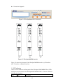
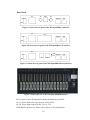
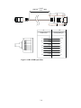
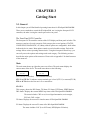
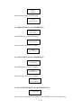
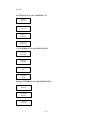
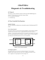
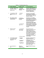
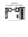
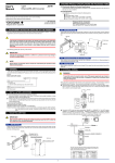
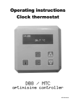
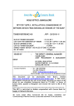
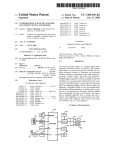
Atrie WireSpan 5000/5000RM User's Manual WireSpan 5000/5000RM USER'S MANUAL ATRIE WireSpan 5000/5000RM USER'S MANUAL (Version 1.01) ATRIE TECHNOLOGY INC. 10th Floor, 14, Lane 609, Sec. 5, Chung Hsin Rd., San Chung City, Taipei Hsien, Taiwan 241, R.O.C. Mail: [email protected] Web site: http//www.atrie.com.tw (C)Copyright 2002 ATRIE TECHNOLOGY INC. CONTENTS CHAPTER 1 Introduction……...……..……..…………1-1 CHAPTER 2 Installation and Setup………………..…2-1 CHAPTER 3 Getting Start…………………….….……3-1 CHAPTER 4 Diagnostic & Troubleshooting…………4-1 APPENDIX A Interface Specifications…………….….A-1 APPENDIX B Pin Assignment &Cable Definition…...B-1 APPENDIX C MDSL G703 MENU TREE……….….C-1 APPENDIX D MDSL V35 MENU TREE…………..…D-1 APPENDIX E MDSL Ethernet MENU TREE……...…E-1 CHAPTER 1 Introduction 1-1Overview The Atrie WireSpan 5000/5000RM G.SHDSL (Giga Single-pair High-bit-rate Digital Subscriber Line) System provides full duplex capability of supporting selected symmetric user data rates of E1 or n x 64 kbit/s (range from 64 kbit/s to 2304 kbit/s) leased line services extension using a Trellis Coded Pulse Amplitude Modulation (TCPAM)/AMI line code over one non-loaded two-wire metallic cable pair. The line speed for transmitted and received data are multiple for lengthening the transmission distance with 10KM down to 6.5Km(2Mbps) at 24AWG (0.5mm). The operation and performance of this specification is complying with symmetric GSHDSL spectrum defined in Annex A, ITU-T Rec. G.991.2. Application Figure1-1 shows a typical WireSpan5000/5000RM application Figure1-1 Typical WireSpan 5000 series application Feature z z z z Compliance with ITU-T G.991.2 (G.SHDSL) Support auto data rates adaptation between 64K and 2304K (N=1~36) V.35, X.21, EIA530, E1 & E1 Fractional interface, Ethernet interface Full function LCD configuration with remote configuration 1-1 z z z Built-in test pattern generator/detector SNMP management through Ethernet LAN port Software flash upgradeable 1-2 Physical Description WireSpan5000 are designed for desktop installation and WireSpan5000RM are designed for mounted in a 19” rack. Installation procedures for the WireSpan5000/5000RM models and respective versions are provided in Chapter 2,Installation and setup. Front Panel Figure 1-2 shows a general view of WireSpan5000 Figure 1- 2. General View 1-2 LED’s The LED indicators on the front panel indicate the operating status of WireSpan5000. Various indicators display status of line, status of data activity, alert condition, and test loop activity in the system. Connectors The power and interface connectors are located on the rear panel of WireSpan5000/5000RM. 1-3 Functional Description WireSpan5000 has a synchronous user’s data port interface: E1 interface, ITU-T V.35, EIA RS-449/RS-530, X.21 or Ethernet interface. They are all changeable module. WireSpan5000RM also supported by means of adapter cables. The user’s data port is terminated in a 25-pin D-type female connector. 1-4 Technical Specifications 1-3 E1 Interface Framing options Unframed mode Framed mode Framed CRC mode Line rate 2.048 Mbps +/-32 ppm Line code HDB3 ,AMI Line impedance Balanced interface – 120 ohms Unbalanced interface – 75 ohms Signal levels Transmit level: Balanced interface - +/- 3V +/- 10% Unbalanced interface - +/- 2.37 +/- 10% Jitter performance Meet ITU-T Rec. G.823 Connectors Balanced interface – RJ-48 eight-pin connector Unbalanced interface – Two BNC coaxial connectors User’s Data Port Interface V.35 or RS-449/RS-530/X.21 Bit rates N x 64K bps (N= 1~36) Clock modes External, Internal Control signals CTS follows RTS or always ON. DSR follows DTR or always ON DCD normal or always ON Ethernet Interface Type Auto-sensing 10/100 BASE-T Ethernet Connector RJ-45 (to PC or HUB) Bridging Dynamically learning and aging up to 1,024 MAC addresses Filtering Rates 14,800bps (10Mbps) Diagnostics Test loops Local analog loopback Remote digital loopback. Indicators Power indicator Line synchronous indicator Test active indicator E1 synchronous indicator AIS indicator Alarm indicator SQ indicator LINK indicator ACT indicator 1-4 Mechanical Standalone Unit Characteristics Height-- 40mm(max) Width-- 177mm(max) Depth-- 260mm(max) Weight—878g 19”rack Height-- 20mm(max) Card version Width-- 150mm(max) Depth-- 241mm(max) Weight—260g Power Requirements Standalone Unit Supply voltage: AC: 85 ~ 264 VAC , 50/60 HZ DC: -35 ~ - 72 VDC (AC and DC) 19” rack 5W, provided by rack Card version Environmental Temperature 0 to 50° C (32 to 122°F) Characteristics Humidity Up to 90%, non-condensing 1-5 CHAPTER 2 Installation and Setup 2-1 General This chapter describes how to install and connect your WireSpan5000/5000RM. Step-by-step instructions guide you through installing your WireSpan5000/5000RM. 2-2 Package Contents For WireSpan5000. The package should contain the following items: 1. The WireSpan5000. 2. One power cable. 3. One user's manual (CD) 4. One telephone cable and one terminal box for RJ-45 5. One RJ-45/D-SUB9 (F) console cable. 6. One CAT.5 UTP cable (Only for Ethernet interface) For WireSpan5000RM. The package should contain the following Items: 1.The WireSpan 5000RM card. 2.One DTE Interface cable (only for V.35 interface). 3. One CAT.5 UTP cable (Only for Ethernet interface) Please contact your dealer if there are any missing or damaged parts. 2-3 Panel Description Front panel The front panel contains a 2 line 16 character LCD display, four keys labeled EXIT, ENTER, LEFT arrow "<", and RIGHT arrow ">" ; and seven LEDs as shown in Figure 2-1. You can access the device menu tree (see Appendix C) through this front panel. Using the menu tree and front panel control keys, you can: z Configuration your WireSpan5000 device. z Save and load the configuration profile. z View status information. 2-1 z Execute the diagnostic. Figure 2-1 WireSpan5000 series front panel. (a) (b) (c) Figure 2-2 WireSpan5000RM interface Figure 2-2 shows the front panel of the WireSpan5000RM interface. (a)E1 interface. (b)V.35 interface. (c)Ethernet interface. 1. LED Indicators There are seven LEDs on the front panel of the WireSpan 5000/5000RM. These LEDs display the real-time status of the WireSpan5000/5000RM.Table 2-1 lists the LEDs and describes their function. LED Name Description 2-2 PWR POWER Lights to indicate that the power is apply to the device L1 LOOP1 Lights to indicate that MDSL loop1 is in sync. L2 LOOP2 Lights to indicate that MDSL loop2 is in sync. TST Test Mode Lights to indicate that the device is in test mode. ■ The LED is always on when in loopback mode. ■ The LED is flesh when in Test pattern mode. SYN/DCD Frame Sync In E1 mode: Lights to indicate that the device has synchronized to the E1 receive signal framing. In V.35 mode: Lights to indicate that data and carrier detect(DCD). AIS/DTR Alarm Indication In E1 mode: Signal Lights to indicate when two consecutive double frames each contain two or fewer zeros out of 512 bits, and when framing alignment is lost. In V.35 mode: Lights to indicate that data terminal ready(DTR). ALM Alarm Lights to indicate the alarm conditions in MDSL. SQ Signal Quality Lights to indicate the signal quality in MDSL. ACT Active Lights to indicate the data transmitting/receiving conditions in Ethernet LINK Link Lights to indicate the link conditions in Ethernet. 2. Control Keys The front panel's four control keys allow you to access the configuration menus, options, and settings that appear in the front panel display. Table 2-2 lists and describes the function of each control key. Table 2-2 Front Panel Keys Keys Functions EXIT Exit to upper menu or abort execution command ENTER Enter menu or confirm your choice LEFT Select next left menu RIGHT Select next right menu 3. LCD Display The front panel LCD display is a 2*16 alphanumerical display. It displays the status and configurations of the WireSpan 5000/5000RM. Please refer to Chapter 3 for detail operation of the LCD display. 2-3 Rear Panel AC G.70 3 TX RX C ONSO LE ON LINE OFF Figure 2-3 shows the rear panel of the WireSpan5000 E1 interface. AC V.3 5 C ONSO LE ON LINE OFF Figure 2-4 shows the rear panel of the WireSpan5000 V.35 interface. AC L INK C ONSO LE ON OFF A CT PC LINE HUB Figure 2-5 shows the rear panel of the WireSpan5000 Ethernet interface. Figure 2-6 shows the rear of the WireSpan 5000RM interface The rear panel of your WireSpan5000 contains the following connectors: AC: AC Power Input (auto-range from AC 90V to 260V) DC: DC Power Input (range from DC -36V to -72V) LINE: MDSL Line Interface. Please refer to Figure 2-7 for pin definition. 2-4 G703: E1 Line Interface. Include 75 Ohm for Coaxial Cable and 120 Ohm for Twisted Pair. Please refer to Figure 2-8 for pin definition. Warning: Do not connect to both the balanced and unbalanced connectors! DTE: DTE Interface. Please refer to Appendix B for pin definition. Note: this connector does not include in WireSpan5000. CONSOLE: Console Port. Please refer to Figure 2-9 2-10 for setting and pin define. ACT: Data transmitting/receiving status in Ethernet LINK: Link status in Ethernet. 12345678 Note: 4. TIP for SHDSL loop. 5. RING for SHDSL loop. Figure 2-7 RJ-45 for SHDSL Line interface (Stand-along Model) 12345678 Note: 1: Receive TIP1 for E1 loop 2: Receive RING1 for E1 loop 4: Transmit TIP2 for E1 loop 5: Transmit RING2 for E1 loop 7: Ground 8: Ground Figure 2-8 RJ-48C for E1 Line interface (Stand-along Model) Figure 2-9 Terminal block for SHDSL and E1/G.703 line 2-5 10 BASE T Note: 1:TD 2:TD 3:RD 6:RD 87654321 Figure 2-10 RJ-45 for LAN interface Note: 1: L1A 2: L1B 3: L2A 4: L2B 5: G703TXA 6: G703TXB 7: G703RXA 8: G703RXB 87654321 Figure 2-11 RJ-45 for SHDSL and E1/G.703 line CH6 CH5 CH4 CH5 CH3 CH2 CH3 CH1 CH1 87654321 10 BASE T I 1 LA 2 LB III II L1A L1A L1B L1B 3 PA L2A L2A 4 PB L2B L2B 5 TXA 6 TXB G703TXA G703TXB 7 RXA 8 RXB G703RXA ON OFF FG G703RXB DC-48V GND 2-6 CONSOLE CH0 CH1 CH2 CH3 CH4 CH5 Figure 2-12 WireSpan 5000RM rear panel AC POWER Parameter Value Speed (Baud Rate) 38400 Data Bits 8 Parity None Stop Bits 1 Terminal Emulation VT-100 or ANSI Figure 2-13 Console port setting 2-7 1000.00 +10.00 MM -10.00 A B RS232(DBG)(F) RJ45 8 PIN 8 1 2 3 4 5 1 6 7 8 Figure 2-14 RJ-45/DB-9 pin define 2-8 FG RTS RXD DCD TXD DTR SG CTS FG 7 3 1 2 4 5 8 CHAPTER 3 Getting Start 3-1 General In this chapter you will find detailed operating instructions for WireSpan5000/5000RM. There are two methods to control the WireSpan5000, one is using the front panel LCD controller; the other is using the console port on the rear panel. The Front Panel LCD Controller The front panel LCD controller consists of the LCD display and front panel switches. The menu tree consists of several categories. Each category has several options (STATUS, CONFIGURE, DIAGNOSTIC, etc.) Many of these options are configurable, while others indicate the device status. Most options contain several selectable settings. Each of the settings affects various operating characteristics. Using the front panel control keys, you can easily access the options and settings under each category. The following sections describe the major options of the menu tree. Please refer to Appendix C for detail structure of the menu tree. Main The main menu shows up right after power on self test. The main menu displays the current status of the device. The main menu shows as the following: STU-C HS FIX 2048 (For G.703/V.35 Interface) STU-C HS FIX 2312 (For Ethernet Interface) STU-C or STU-R: To indicate current terminal type is local (STU-C) or remote(STU-R) FIX or AUTO: show the line rate is fix or auto detect. STATUS This category shows the DSL Status, TS Status, E1 Status, DTE Status, PERF Monitor. DSL Status: Displays the current MDSL loop status of the WireSpan5000/5000RM. The status includes: CRC error, far end signal attenuation, noise margin, PLL lock, DSL version. TS Status: Displays the current E1 timeslot status of WireSpan5000/5000RM. E1 Status: Displays the current E1 status of the WireSpan5000/5000RM. The status includes: LOF (Loss Of Frame), BPV(Bipolar Violation), 3-1 FERR (Framing Error), CERR(CRC Error), LCV(Line Code Violation), DTE Status: Display the current DTE status. The status includes: RTS, CTS, DSR, DTR, DCD, TST. LAN Status: Display the current LAN status. The status includes:10M/100M LAN speed, FULL/HALF duplex, LINK UP/DOWN. CONFIGURE The configure category configures the WireSpan5000/5000RM. DSL Setup: Configure the DSL parameters, such as: DSL type, DSL speed. DTE Setup: Configures the DTE parameters, such as: INF clock, Clki polarity, Clko polarity, DCD, DSR, CTS option. E1 Setup: Configure the E1 parameters, Framing, Interface, Idle code, Line coding, Ts0 insert. Clock source: Configure clock parameters, such as: Internal, External. Aux: Configure aux parameters, such as: Set keylock, Keylock password, PERM auto claern. TS Mapping: Configure the timeslots mapping, DSL Re-link: Re-link the DSL line. NOTE: When change any setting. You must be re-link the DSL line. SYS RST: Reset to the default parameters. DIAGNOSTIC The diagnostic allows user to do variety of loop back to assist user in isolating network problem. PROFILE The WireSpan5000/5000RM supports 5 user profiles to save for future use. Also provide four factory default profiles to load. Menu Tree Operation MAIN PANEL CTRL Local Remote You can configure the WireSpan 5000/5000RM of central side (L) or remote side (R) at the central side. 3-2 1. STATUS MENU [MAIN ] STATUS This Menu shows the DSL STATUS, E1 STATUS and other status display. 2. CONFIGURE MENU [MAIN ] CONFIGURE You can configure the WireSpan5000/5000RM through this menu to get the best performance. 3. DIAGNOSTIC MENU (Ethernet interface not supported) [MAIN ] DIAGNOSTIC This menu provide self-test, helping user to find out the problem and fix it. 4. PROFILE MENU [MAIN ] PROFILE This menu provides the user 5 user profile to save or load, also provide the factory setting. 1. STATUS MENU [MAIN ] STATUS 1.1 DSL STATUS Press ENTER key to enter DSL status menu. <STATUS> DSL STATUS This screen shows the DSL Loop status, press ENTER to show loop status. 1.1.1 HDSL CRC ERROR COUNT STATUS SCREEN 3-3 CERR L1:*** L2:*** Press Right key shows the CERR STATUS. 1.1.2 FAR-END SIGNAL ATTENUATION DISPLAY FESAL1:*** db L2:*** db Press Right key shows the FESA STATUS. 1.1.3 NOISE MARGIN DISPLAY NMR L1:*** db L2:*** db This screen shows the DSL Loop receiving Noise Margin. Press Right key to show the Noise Margin Display. 1.1.4 PLL LOCK DISPLAY (Ethernet interface not supported) (See the APPENDIX D-2) PLLK L1:* L2:N/A This screen shows the DSL PLL Lock status. Press Right key to show it. 1.1.5 DSP VERSION DISPLAY (See the APPENDIX D-2) DSP: X.3 AFE:X.5 This screen shows the DSP version. Press Right key to show it. 1.2 DTE STATUS (Only support V.35, X.21, EIA530, RS449 interface) (See the APPENDIX D-2) <STATUS> DTE This screen displays WireSpan 5000/5000RM DTE interface signal status. Press ENTER to show the signal status. 3-4 RTS_ CTS_ TST_ DSR_ DTR_ DCD_ This screen display the DTE interface control signal status. 1.2 TS STATUS ( Only support E1 interface ) (See the APPENDIX C-2) <STATUS> TS STATUS This screen displays WireSpan 5000/5000RM E1 timeslot mapping status. Press ENTER to show the signal status. [CH00~07] ******** This screen display the E1 timeslot 0 ~ 7 mapping status. [CH08~15] ******** This screen display the E1 timeslot 8 ~ 15 mapping status. Press Right key to show it. [CH16~23] ******** This screen display the E1 timeslot 16 ~ 23 mapping status. Press Right key to show it. [CH24~31] ******** This screen display the E1 timeslot 24 ~ 31 mapping status. Press Right key to show it. 1.3 E1 STATUS (Only support E1 interface ) (See the APPENDIX C-2) <STATUS> E1 STATUS This screen displays WireSpan 5000/5000RM E1 interface signal status. Press ENTER to show the signal status. 1.3.1 E1 LOCAL STATUS (See the APPENDIX C-2) LOF * BPV * 3-5 LOF = Loss Frame BPV = Bipolar Violation There will be * mark shown beside each alarm if present. 1.3.2 FRAMING ERROR AND CRC ERROR COUNTER (See the APPENDIX C-2) FERR:***** CERR:***** FERR = Framing Error count CERR = CRC Error count This screen displays WireSpan 5000/5000RM E1 framing error and CRC error count. Press Right key to show the signal status. LCV:*** FEBE:*** LCV = Line Code Violation count FEBE = Far-End Block Error count This screen displays WireSpan 5000/5000RM E1 LCV error and FEBE error count. Press Right key to show the signal status. 1.2 Ethernet STATUS ( Only support Ethernet interface ) (See the APPENDIX E-2) <STATUS> LAN STATUS This screen displays WireSpan 5000/5000RM Ethernet interface signal status. Press ENTER to show the signal status. 100M FULL LINK UP This screen display the Ethernet interface signal status of linking up/down, 10M/100M, full/half duplex. 1.3 PERFORMANCE MONITOR (See the APPENDIX E-2) <STATUS> PERF MONITOR The performance monitor shows the E1 and DSL Receiving signal performance. 3-6 Press the ENTER key to enter the performance screen. 1.3.2 E1 or DSL PERFORMANCE MONITOR (15 MINUTES) (See the APPENDIX E-2) <<<XXX PERF>>> 15M ES 15M ES: 15 MINUTE ERROR SECOND The error second count during last 15 minutes. Press Right key to show the signal status 1.3.3 E1 or DSL SEVERELY PERFORMANCE MONITOR (15 MINUTES) (See the APPENDIX E-2) <<<XXX PERF>>> 15M SES 15M SES: 15 MINUTES SEVERELY ERROR SECOND The second count of error more than 30% in each second during last 15 minutes. Press Right key to show it. 1.3.4 E1 or DSL PERFORMANCE MONITOR (24 HOURS) (See the APPENDIX E-2) <<<XXX PERF>>> 24H ES 24H ES: 24 HOURS ERROR SECOND Press Right key to show it. 1.3.5 E1 or DSL SEVERELY PERFORMANCE MONITOR (24 HOURS) (See the APPENDIX E-2) <<<XXX PERF>>> 24H SES 24H SES:24 HOURS SEVERELY ERROR SECOND Press Right key to show it. 2. CONFIGURE MENU [MAIN ] CONFIGURE 3-7 2.1 DSL CONFIGURE MENU <CONFIGURE> DSL This screen can configure the DSL parameter. Press ENTER key to enter DSL setup screen. 2.1.1 DSL TYPE SELECT <<DSL SETUP>> DSL TYPE Use this screen to select central or remote. Two connecting modems must be set to one central and the other remote, otherwise it will not connect. Press ENTER key to select. Use the Left or Right key to select then press ENTER to confirm. [DSL TYPE] STU-C* STU-R NOTE: You must RE-LINK the line when change any setting 2.1.2 DSL SPEED SELECT (E1 interface not supported) (See the APPENDIX D-3) <<DSL SETUP>> DSL SPEED Use this screen to select the DSL line speed. You can select line speed by manual or auto detect. Press the Left or Right key to select then press ENTER to confirm. 2.1.2.1 MANUAL SPEED MENU (See the APPENDIX D-3) <<<DSL SPEED>>> MULTIRATE* Use this screen to select the DSL line speed by manual. The data rate can be N x 64K (N = 1~36 ). (For V.35 Interface) The data rate can be N x 64K (N = 3~36 ). (For Ethernet Interface) [DSL RATE] **** 2.1.2.1.1 AUTO SPEED MENU (See the APPENDIX D-3) 3-8 <<<DSL SPEED>>> AUTO Use this screen to select the DSL line speed by auto detect. 2.2 DTE CONFIGURE MENU ( only support V.35, X.21, EIA530, RS449 interface ) <CONFIGURE> DTE This screen can configure the DTE parameter. Press ENTER key to enter DTE setup screen. 2.2.2 CLOCK INPUT POLARITY (See the APPENDIX D-3) <<DTE SETUP>> CLKI POLARITY This screen selects the polarity of the clock input. [CLKI INV] NORM* INV Select the Normal or Inverse input of clock signal. 2.2.3 CLOCK OUTPUT POLARITY (See the APPENDIX D-3) <<DTE SETUP>> CLKO POLARITY This screen selects the polarity of the clock output. [CLKO INV] NORM* INV Select the Normal or Inverse output of clock signal. 2.2.4 DCD OPTION (See the APPENDIX D-3) <<DTE SETUP>> DCD OPTION Press ENTER key to select DCD option. 3-9 [DCD] NORMAL Select the desire option for DCD signal. [DCD] ALWAYS ON 2.2.5 DSR OPTION (See the APPENDIX D-3) <<DTE SETUP>> DSR OPTION Press ENTER key to select DSR option. [DSR] ALW AYS ON Select the desire option for DSR signal. [DSR] FOLLOW DTR 2.2.6 CTS OPTION (See the APPENDIX D-3) <<DTE SETUP>> CTS OPTION Press ENTER key to select CTS option. [CTS] ALW AYS ON Select the desire option for CTS signal. [CTS] FOLLOW RTS 2.2 E1 CONFIGURE MENU (See the APPENDIX C-3) <CONFIGURE> E1 This screen can configure the E1 parameter. Press ENTER to enter E1 Framing setup 3-10 screen. 2.2.1 E1 FRAMING SETUP SCREEN (See the APPENDIX C-3) <<E1 SETUP>> FRAMING Press ENTER to select E1 Framing. [FRAMING] FRAMED Press Left or Right key to select FRAMED or FRAMED CRC or UNFRAMED. [FRAMING] FRAMED CRC [FRAMING] UNFRAMED 2.2.2 E1 INTERFACE SELECT (See the APPENDIX C-3) <<E1 SETUP>> INTERFACE Select the desire Interface for E1. The WireSpan5000/5000RM provide RJ45 with 120 Ohm or BNC connector with 75 Ohm. Press ENTER to select. Use the Left or Right key to select then press ENRER to confirm. [INTERFACE] 120 OHM TP [INTERFACE] 75 OHM COAXIAL 2.2.3 E1 IDLE CODE SELECT (See the APPENDIX C-3) <<E1 SETUP>> IDLE CODE There are two idle codes for selection. Press ENTER to select. 3-11 [IDL CODE] 7F* FF Use Left or Right key to select "7F" or "FF" idle code. 2.2.4 E1 LINE CODING SELECT (See the APPENDIX C-3) <<E1 SETUP>> LINE CODING There are two methods of line coding. Press ENTER to select. [CODING] HDB3* AMI Use Left or Right key to select AMI or HDB3 line coding. 2.2.5 E1 TIMESLOT0 INSERT SELECT (See the APPENDIX C-3) <<E1 SETUP>> TS0 INSERT There are two methods of line coding. Press ENTER to select. [TS0 INSERT] YES NO * Use Left or Right key to select YES to insert E1 framing. NOTE: When one side is E1 interface and the other side is use DTE interface, this option must be set to “YES”. 2.3 CLOCK SOURCE CONFIGURE MENU (only supported in STU-C side ) (Ethernet interface not supported) < C O N F IG U R E > CLK SOURCE There are INTERNAL, EXTERNAL clock sources. Use Left or Right key to select desire clock source. [CLK SRC] INTERNAL [CLK SRC] EXTERNAL 3-12 2.4 AUX CONFIGURE MENU < C O N F IG U R E > AUX 2.4.1 KEYLOCK SETTING <<AUX>> SET KEYLOCK This screen allows user to lock the four front panel keys. You must key in password before activate, the key lock function. Use Left or Right key to select key lock ON/OFF. [KEY LOCK] ON OFF* 2.4.2.1 KEYLOCK PASSWORD SETTING [OLD PWD ?] IN:**** The password contains ten numerical characters. You must enter 10 digit of number. If you want to change old password, you have to enter old password first, then enter the new password. [NEW PWD ?] IN:**** 2.4.3 PERFORMANCE ATUO CLEAR SETTING <<AUX>> PERM AUTO CLR This screen will auto clears all performance error counter when the line link is up. [PM AUTOCLR] ON* OFF 2.5 TIMESLOT MAPPING CONFIGURE MENU ( only supported in E1 interface ) (See the APPENDIX C-4) 3-13 <CONFIGURE> TS M APPING The WireSpan 5000/5000RM provides Fractional E1 function. In this function , it allows user to assign every 64 kbps bandwidth to be used in E1 interface. Please note that each STU-C and STU-R to be connected must be assigned in same Timeslot Mapping. [ALL TS] * In this screen, You can select all timeslots in E1 or Idle mode. [C H 0 0 ~ 0 7 ] F * * * * * * * In this screen, You can assign any channel from CH01 up to Ch31. [C H 0 8 ~ 1 5 ] * * * * * * * * [C H 1 6 ~ 2 3 ] * * * * * * * * [C H 2 4 ~ 3 1 ] * * * * * * * * NOTE: The timeslot mapping will decide the line connect rate. 2.5 DSL RE-LINK CONFIGURE MENU <CONFIGURE> DSL RELINK In this screen, You can re-link the DSL line. It is must to do when you change any setting. NOTE: When you change any setting. You must re-link the DSL line and the parameter will be executed. [DSL RELINK] YES* NO 2.6 SYSTEM RESET CONFIGURE MENU 3-14 <CONFIGURE> SYS RST Press ENTER key to enter SYSTEM RESET screen. [SYS RST] YES* NO Use Left or Right key to select YES then press ENTER. 3. DIAGNOSTIC MENU (Ethernet interface not supported) [MAIN ] DIAGNOSTIC Through the diagnostic, the user can separate and fix the communication problem. There are three loopback test. Detail test description will be found on Chapter 4. 3.1 LOCAL ANALOG LOOPBACK MENU (See the APPENDIX C-5;D-5) <DIAGNOSTIC> LLB Pressing the ENTER key activates the local analog loopback. The local analog loopback returns the data sent by the local equipment. 3.2 LOCAL DIGITAL LOOPBACK MENU (See the APPENDIX C-5;D-5) <DIAGNOSTIC> DLB Pressing the ENTER key activates the local digital loopback. The local digital loopback returns the data sent by the remote equipment. 3.3 REMOTE DIGITAL LOOPBACK MENU ( only supported in STU-C ) (See the APPENDIX C-5;D-5) <DIAGNOSTIC> RDL Pressing the ENTER key activates the remote digital loopback. This causes a loopback activation command to be sent in-band to remote WireSpan5000/5000RM. 3.4 TEST PATTERN MENU (See the APPENDIX C-5;D-5) 3-15 <DIAGNOSTIC> TP Pressing the ENTER key activates the BER testing. Detail test description will be found on Chapter 4. [ER R C OUNT] **** 4 PROFILE MENU [MAIN ] PROFILE There are four preset profiles for user to load, and five user profiles can be saved by user for later load. 4.1 LOAD PROFILE MENU <PROFILE> LOAD [LOAD] 1* 2 3 4 5 Use Left or Right key to select profile and press ENTER to load. 4.2 SAVE PROFILE MENU <PROFILE> SAVE [SAVE] 1* 2 3 4 5 Use Left or Right key to select profile and press ENTER to save. 4.3 LOAD DEFAULT PROFILE <PROFILE> LOAD DEFAULT There are four factary default for user to load. Use Left or Right key to select and ENTER 3-16 to load. E1 INTERFACE (See the APPENDIX C-5) [1:STU-C] FAS 120 [2:STU-R] FAS 120 [3:STU-C] FAS+CRC 75 [4:STU-R] FAS+CRC 75 V.35 INTERFACE (See the APPENDIX D-5) [1:STU-C] FIX 2048 [2:STU-R] FIX 2048 [3:STU-C] AUTO [4:STU-R] AUTO Ethernet INTERFACE (See the APPENDIX E-4) [1:STU-C] FIX 2312 [2:STU-R] FIX 2312 [3:STU-C] FIX 200 3-17 [4:STU-R] FIX 200 3-18 CHAPTER 4 Diagnostic & Troubleshooting 4-1 General This chapter presents information related to the Wirespan 5000/5000RM diagnostics functions. The information presented in this chapter include: 4.1 User-controlled test functions. 4.2 Troubleshooting. 4-2 User-Controlled Test Functions Loopback Function The user-controlled test functions are activated by means of the buttons and LCD screen. Local Analog Loopback Pressing the LLB screen activates the local analog loopback. The local analog Loopback returns the data sent by the local user’s equipment (DTE) towards the local user’s equipment. Connecting the main link performs the loopback transmit signal to the input of the receive path within the DSL line interface, as Shown in Figure 4-1. The test signal is provided by the local DTE, that must receive its own transmission. WireSpan5000/5000RM User Port Interface DSL Interface Figure 4-1 Local Analog Loopback Local Digital Loopback Pressing the DLB screen activates the local digital loopback. The local digital loopback returns the data sent by the remote user’s equipment towards the remote User’s equipment. The signal paths are shown in Figure 4-2. 4-1 WireSpan5000/5000RM User Port Interface DSL Interface Figure 4-2 Local Digital Loopback Remote Digital Loopback (only supported in STU-C ) Pressing the RDL screen activates the remote digital loopback. This causes a loopback activation command to be sent in-band to the remote WireSpan 5000/5000RM, thus User’s data transmission is interrupted immediately. Since the code is sent via the DSL line, the loopback will be connedted only if the remote WireSpan 5000/5000RM can receive the activation code. If loopback connection is confirmed, the TEST indicator will turn on. The remote digital loopback returns the data sent by the local user’s equipment towards the local user’s equipment. The loopback is performed by connecting the remote data port receice signal to the input of the data port transmit path, within the data port interfaces of the remote WireSpan 5000/5000RM. Signal paths are shown in Figure 4-3. The test signal is provided by the local DTE, that must receive its own transmission. This test fully checks the data link, including the cables connecting the local DTE to The WireSpan 5000/5000RM, the remote WireSpan 5000/5000RM, the DSL line connecting the two WireSpan 5000/5000RM.. 4-2 Local Wirepan 5000/5000RM Remote Wirepan 5000/5000RM User Port DSL DSL User Port Interface Interface Interface Interface Figure 4-3 Remote Digital Loopback BER Testing Pressing the PT screen activates BER testing. During the test, the Internal pattern generator connects a digital test signal to the transmit input of the local data channel interface. The test signal is a 2047 sequence. The transmitted data can either be returned to the receive path by means of a loop somewhere along the data path (e.g., by connecting the local analog loopback or the remote digital loopback ), or a similar sequence can be transmitted from the other end of the data channel (by simultaneously pressing the PT screen at the remote WireSpan 5000/5000RM, or by connecting a test pattern generator). The receive path output signal is connected to a pattern evaluator. The evaluator compares the received and transmitted patterns and detects errors. The Result is presented by means of the ERR COUNT that has been detected during the testing. This test is used to obtain a rapid qualitative evaluation of data transmission without using external test equipment. 4-3 Troubleshooting Instructions Preliminary Checks In case a problem occurs, perform the following preliminary checks: Check the configuration of the local and remote WireSpan 5000/5000RM units against the prescribed configuration Check cable connections, and the equipment used on the DSL line connecting the local WireSpan 5000/5000RM to the remote equipment Observe the front-panel indicators and analyze the indications. Refer to Status Indications for descriptions of indicator functions. 4-3 Troubleshooting If the trouble cannot be corrected by performing the preliminary checks listed above, use the information in Table 4-1 to identify the trouble symptoms and perform the actions listed under Corrective Measures in the order given until the problem is corrected. If the problem cannot be corrected by carrying out the listed actions, have the WireSpan 5000/5000RM check by the technical support personnel. 4-4 Table 4-1 Troubleshooting Chart N Trouble Symptoms Probable Cause Corrective Measures 1 WireSpan 5000/5000RM are dead ( all the indicators,including PWR, are off) 1. No power 2. Defective WireSpan 5000/ 5000RM Check that both ends of the WireSpan 5000/5000RM power cable are properly connected, and that power is available at the outlet Replace the WireSpan 5000/5000RM 2 Local WireSpan 5000 /5000RMreports sync loss 1. External problem Activate the local loopback. Check that local WireSpan 5000/5000RM SYN indicator is ON. If the indicator is ON, the problem is external 3 BPV indicator on the local Wirespan 5000 /5000RM blinks 1. Defective Wirespan 5000 /5000RM Activate the local loopback. Check that the local WireSpan 5000/5000RM SYN indicator is On.If indicator off, turn the local Wirespan 5000/5000RM on with the local loopback activated.Check that the BPV and AIS alarm indicator turns off. If not, replace the WireSpan 5000/5000RM Troubleshoot the E1 link between the local and the remote WireSpan 5000/ 5000RM 2. Problems on the E1 link 4 Data port control signals are off 1. Local user’s equipment is off, or is idle 2. Defective cable 5 Local equipment does not receive the data sent by the remote equipment 1. External problem 2. Problem at local end 3. Problem at remote end 6 No transmission of data Data port interface not inserted correctly 4-5 Check that the user’s quipment is powered, and its control signal lines are asserted. Perform self-test on the equipment Activate the local loopback, and check that the local user;s equipment receives its own transmission. If not, replace the cable connecting it to the Wirespan 5000/5000RM Activate the digital loopback, and check remote E1 equipment receives its own transmission. If not, troubleshoot the remote Wirespan 5000/5000RM and thee E1 link Perform the activities listed in No.4 above Perform the activities listed in No.4 above Re-insert data port interface cable APPENDIX A Interface Specifications A.1 E1 Balanced Port Connector The E1 balance port interface is terminated in an eight-pin RJ-48C connector, Designated E1 LINK, and wired in accordance with Table A-1. Pin Function 1 Receiver Data In (tip) 2 Receiver Data In (ring) 3 Not Connected 4 Transmit Data Out (tip) 5 Transmit Data Out (ring) 6 Not Connected 7 Shield 8 Shield Table A-1. E1 LINK Connector, Pin Allocation A-1 APPENDIX B Pin Assignment &Cable Definition Figure B-1 Dedicated V.35 Change-Cable Definition B-1 MDSL/G703 MU:1.0 ROM:1.0 STU-C HS FIX 2048 PANEL CTRL Local Remote [MAIN ] STATUS [MAIN ] CONFIGURE [MAIN ] DIAGNOSTIC [MAIN ] PROFILE [MAIN ] STATUS <STATUS> TS STATUS [MAIN ] CONFIGURE FRAMED 120 OHM HDB3 <STATUS> DSL STATUS <CONFIGURE> E1 <PROFILE> SAVE [MAIN ] PROFILE <STATUS> PERF MONITOR <CONFIGURE> AUX <DIAGNOSTIC> TP <CONFIGURE> TS MAPPING APPENDIX C MDSL/G.703 MENU TREE [MAIN ] DIAGNOSTIC <STATUS> E1 STATUS <CONFIGURE> CLK SOURCE <DIAGNOSTIC> RDL <PROFILE> LOAD DEFAULT <DIAGNOSTIC> DLB <CONFIGURE> DSL <DIAGNOSTIC> LLB <PROFILE> LOAD <CONFIGURE> DSL RELINK *: Current setting <CONFIGURE> SYS RST Only Appear in STU_C C-1 <STATUS> DSL STATUS <STATUS> TS STATUS <STATUS> E1 STATUS <STATUS> PERF MONITOR CRC Error Count FESA L1:*** db L2:*** db Far-End Signal Attenuation Noise Margin 1 Day Error Second <<<XXX PERF>>> 24H SES 1 Day Severely Error Second [CH24~31] ******** NMR L1:*** db L2:*** db [CH16~23] ******** Line Code Violation LCV:*** FEBE:*** 15Min Severely Error Second <<<XXX PERF>>> 24H ES Far-End Block Error 15Min Error Second <<<XXX PERF>>> 15M SES CRC Error FERR:***** CERR:*** Framing Error [CH08~15] ******** CERR L1:*** L2:* * * [CH00~07] ******** Loss Frame LOF * BPV * Bipolar Violation <<<XXX PERF>>> 15M ES [24H SES] 0: *** Sec <<PERF>> E1 <<PERF>> DSL L1 [24H ES] 0: *** Sec 0,-1 [15M SES] 0: *** Sec 0,-1 [15M ES] 0: *** Sec 0 ~ -31 <<PERF>> DSL L2 0 ~ -31 C-2 <CONFIGURE> DSL <CONFIGURE> E1 <<DSL SETUP>> DSL TYPE [DSL TYPE] STU-C* STU-R <<E1 SETUP>> FRAMING <<E1 SETUP>> INTERFACE <<E1 SETUP>> IDLE CODE <<E1 SETUP>> LINE CODING <<E1 SETUP>> TS0 INSERT [INTERFACE] 120 OHM TP [FRAMING] FRAMED [INTERFACE] 75 OHM COAXIAL [FRAMING] FRAMED CRC [IDL CODE] 7F* FF [CODING] HDB3* AMI [TS0 INSERT] YES NO * [FRAMING] UNFRAMED C-3 <CONFIGURE> CLK SOURCE <CONFIGURE> AUX <CONFIGURE> TS MAPPING [ALL TS] * <CONFIGURE> DSL RELINK <CONFIGURE> SYS RST [CLK SRC] INTERNAL <<AUX>> SET KEYLOCK <<AUX>> KEYLOCK PW <<AUX>> PERM AUTO CLR [CH00~07] F******* [DSL RELINK] YES* NO [SYS RST] YES* NO [CLK SRC] EXTERNAL [KEY LOCK] ON OFF* [OLD PWD ?] IN:**** [PM AUTOCLR] ON* OFF *:E(E1),I(IDLE) [CH08~15] ******** [NEW PWD ?] IN:**** [CH16~23] ******** [CH24~31] ******** C-4 <DIAGNOSTIC> LLB [DSL LLB] ON OFF* <PROFILE> LOAD <PROFILE> SAVE <PROFILE> LOAD DEFAULT <DIAGNOSTIC> DLB <DIAGNOSTIC> RDL [TST PATTERN] ON OFF* <DIAGNOSTIC> TP [3:STU-C] FAS+CRC 75 [DSL RDL] ON OFF* [2:STU-R] FAS 120 [DSL DLB] ON OFF* [LOAD] 1* 2 3 4 5 [SAVE] 1* 2 3 4 5 [1:STU-C] FAS 120 [ERR COUNT] **** [4:STU-R] FAS+CRC 75 C-5 MDSL/V35 MU:1.0 ROM:1.0 STU-C FIX 2048 PANEL CTRL Local Remote [MAIN] STATUS [MAIN ] CONFIGURE [MAIN ] DIAGNOSTIC [MAIN ] PROFILE [MAIN ] STATUS <STATUS> DTE STATUS [MAIN ] CONFIGURE <STATUS> PERF MONITOR [MAIN ] DIAGNOSTIC [MAIN] PROFILE <CONFIGURE> CLK SOURCE <DIAGNOSTIC> TP <CONFIGURE> DSL RELINK APPENDIX D MDSL/V.35 MENU TREE <STATUS> DSL STATUS <PROFILE> LOAD DEFAULT <DIAGNOSTIC> RDL <CONFIGURE> AUX <CONFIGURE> DTE <PROFILE> SAVE <DIAGNOSTIC> DLB <CONFIGURE> DSL <DIAGNOSTIC> LLB <PROFILE> LOAD <CONFIGURE> SYS RST *: Current setting Only Appear in STU_C D-1 <STATUS> DSL STATUS <STATUS> DTE <STATUS> PERF MONITOR CERR L1:*** L2:* * * CRC Error Count FESA L1:*** db L2:*** db Far-End Signal Attenuation PLL Lock DSL Version 1 Day Severely Error Second Noise Margin 1 Day Error Second <<<XXX PERF>>> 24H SES DSP: X.3 AFE:X.5 15Min Severely Error Second <<<XXX PERF>>> 24H ES PLLK L1:* L2:N/A 15Min Error Second <<<XXX PERF>>> 15M SES NMR L1:*** db L2:*** db <<<XXX PERF>>> 15M ES [24H SES] 0: *** Sec RTS_ CTS_ TST_ DSR_ DTR_ DCD_ <<PERF>> DSL L1 [24H ES] 0: *** Sec 0,-1 [15M SES] 0: *** Sec 0,-1 [15M ES] 0: *** Sec 0 ~ -31 <<PERF>> DSL L2 0 ~ -31 D-2 <CONFIGURE> DSL <CONFIGURE> DTE [DSL TYPE] STU-C* STU-R <<DSL SETUP>> DSL TYPE <<<DSL SPEED>>> MULTIRATE* <<DSL SETUP>> DSL SPEED <<DTE SETUP>> CLKO POLARITY <<<DSL SPEED>>> AUTO <<DTE SETUP>> CLKI POLARITY [CLKO INV] NORM* INV [DSL RATE] **** <<DTE SETUP>> INF CLK [CLKI INV] NORM* INV 64K Base [INF CLK] TXC* EXTC <<DTE SETUP>> DCD OPTION <<DTE SETUP>> DSR OPTION <<DTE SETUP>> CTS OPTION [CTS] ALWAYS ON [DSR] ALWAYS ON [DCD] NORMAL [CTS] FOLLOW RTS [DSR] FOLLOW DTR [DCD] ALWAYS ON D-3 <CONFIGURE> CLK SOURCE <CONFIGURE> AUX <CONFIGURE> DSL RELINK <CONFIGURE> SYS RST [CLK SRC] INTERNAL <<AUX>> SET KEYLOCK <<AUX>> KEYLOCK PW <<AUX>> PERM AUTO CLR [DSL RELINK] YES* NO [SYS RST] YES* NO [CLK SRC] EXTERNAL [KEY LOCK] ON OFF* [OLD PWD ?] IN:**** [PM AUTOCLR] ON* OFF [NEW PWD ?] IN:**** D- 4 <DIAGNOSTIC> LLB [DSL LLB] ON OFF* <PROFILE> LOAD <PROFILE> SAVE <PROFILE> LOAD DEFAULT <DIAGNOSTIC> DLB <DIAGNOSTIC> RDL [TST PATTERN] ON OFF* <DIAGNOSTIC> TP [3:STU-C] AUTO [DSL RDL] ON OFF* [2:STU-R] FIX 2048 [DSL DLB] ON OFF* [LOAD] 1* 2 3 4 5 [SAVE] 1* 2 3 4 5 [1:STU-C] FIX 2048 [ERR COUNT] **** [4:STU-R] AUTO D-5 MDSL/BRIDGE MU:1.0 ROM:1.0 STU-C HS FIX 2312 PANEL CTRL Local Remote [MAIN] STATUS [MAIN] CONFIGURE [MAIN] PROFILE [MAIN] STATUS <STATUS> DSL STATUS <CONFIGURE> DSL <PROFILE> LOAD [MAIN] PROFILE <CONFIGURE> SYS RST *: Current setting APPENDIX E MDSL/Ethernet MENU TREE [MAIN] CONFIGURE <STATUS> PERF MONITOR <CONFIGURE> DSL RELINK <PROFILE> LOAD DEFAULT <STATUS> LAN STATUS <CONFIGURE> AUX <PROFILE> SAVE Only Appear in STU_C E-1 <STATUS> DSL STATUS <STATUS> LAN STATUS <STATUS> PERF MONITOR CERR L1:*** L2:* * * CRC Error Count FESA L1:*** db L2:*** db Far-End Signal Attenuation 10M HALF 100M FULL LINK UP Noise Margin DSL Version 1 Day Error Second <<<XXX PERF>>> 24H SES 1 Day Severely Error Second DSP: X.3 AFE:X.5 15Min Severely Error Second <<<XXX PERF>>> 24H ES NMR L1:*** db L2:*** db <<<XXX PERF>>> 15M SES LINK DOWN <<<XXX PERF>>> 15M ES [24H SES] 0: *** Sec 15Min Error Second <<PERF>> DSL L1 [24H ES] 0: *** Sec 0,-1 [15M SES] 0: *** Sec 0,-1 [15M ES] 0: *** Sec 0 ~ -31 <<PERF>> DSL L2 0 ~ -31 E-2 <CONFIGURE> DSL <CONFIGURE> AUX <CONFIGURE> DSL RELINK <CONFIGURE> SYS RST <<DSL SETUP>> DSL TYPE <<DSL SETUP>> DSL SPEED [NEW PWD ?] IN:**** 64K Base(200K-> 2312K) [DSL RATE] **** <<<DSL SPEED>>> MULTIRATE* [KEY LOCK] ON OFF* [PM AUTOCLR] ON* OFF [OLD PWD ?] IN:**** [DSL TYPE] STU-C* STU-R <<AUX>> SET KEYLOCK <<AUX>> KEYLOCK PW <<AUX>> PERM AUTO CLR [DSL RELINK] YES* NO [SYS RST] YES* NO <<<DSL SPEED>>> AUTO E-3 <PROFILE> LOAD <PROFILE> SAVE <PROFILE> LOAD DEFAULT [LOAD] 1* 2 3 4 5 [SAVE] 1* 2 3 4 5 [1:STU-C] FIX 2312 [2:STU-R] FIX 2312 [3:STU-C] FIX 200 [4:STU-R] FIX 200 E-4