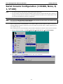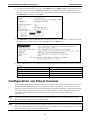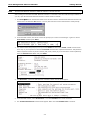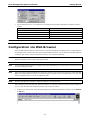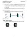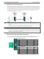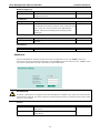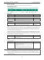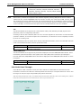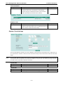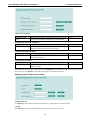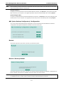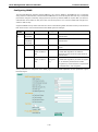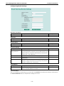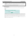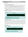
1
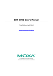
Moxa Managed DSL Ethernet Extender User’s Manual First Edition, March 2013 www.moxa.com/product © 2013 Moxa Inc. All rights reserved. Moxa Managed DSL Ethernet Extender User’s Manual The software described in this manual is furnished under a license agreement and may be used only in accordance with the terms of that agreement. Copyright Notice © 2013 Moxa Inc. All rights reserved. Trademarks The MOXA logo is a registered trademark of Moxa Inc. All other trademarks or registered marks in this manual belong to their respective manufacturers. Disclaimer Information in this document is subject to change without notice and does not represent a commitment on the part of Moxa. Moxa provides this document as is, without warranty of any kind, either expressed or implied, including, but not limited to, its particular purpose. Moxa reserves the right to make improvements and/or changes to this manual, or to the products and/or the programs described in this manual, at any time. Information provided in this manual is intended to be accurate and reliable. However, Moxa assumes no responsibility for its use, or for any infringements on the rights of third parties that may result from its use. This product might include unintentional technical or typographical errors. Changes are periodically made to the information herein to correct such errors, and these changes are incorporated into new editions of the publication. Technical Support Contact Information www.moxa.com/support Moxa Americas Moxa China (Shanghai office) Toll-free: 1-888-669-2872 Toll-free: 800-820-5036 Tel: +1-714-528-6777 Tel: +86-21-5258-9955 Fax: +1-714-528-6778 Fax: +86-21-5258-5505 Moxa Europe Moxa Asia-Pacific Tel: +49-89-3 70 03 99-0 Tel: +886-2-8919-1230 Fax: +49-89-3 70 03 99-99 Fax: +886-2-8919-1231 Moxa India Tel: +91-80-4172-9088 Fax: +91-80-4132-1045 Table of Contents 1. About this Manual ............................................................................................................................. 1-1 2. Getting Started.................................................................................................................................. 2-1 Serial Console Configuration (115200, None, 8, 1, VT100) ....................................................................... 2-2 Configuration via Telnet Console ........................................................................................................... 2-4 Configuration via Web Browser ............................................................................................................. 2-6 Disabling Telnet and Browser Access ..................................................................................................... 2-7 3. Featured Functions ........................................................................................................................... 3-1 Product Overview ............................................................................................................................... 3-2 Wiring the Devices ...................................................................................................................... 3-2 Getting Started ........................................................................................................................... 3-2 4. Diagnostics, Management, and Performance ..................................................................................... 4-1 On-site Troubleshooting ...................................................................................................................... 4-2 Remote Management .......................................................................................................................... 4-3 Performance ...................................................................................................................................... 4-4 A. MIB Groups ....................................................................................................................................... A-1 1 1. About this Manual Thank you for purchasing Moxa’s managed DSL Ethernet extender. Read this user’s manual to learn how to connect your DSL Ethernet extender to Ethernet-enabled devices in industrial applications. The following two chapters are covered in this user manual: Getting Started This chapter explains the initial installation process for the DSL Ethernet extender. There are three ways to access configuration settings: serial console, Telnet console, and web console. Featured Functions This chapter explains how to access various configuration, monitoring, and administration functions. These functions can be accessed via serial, Telnet, or web console. The web console is the most user-friendly way to configure the DSL Ethernet extender. In this chapter, we will use the web console interface to introduce the functions. 2 2. Getting Started This chapter explains how to install a Moxa DSL Ethernet extender for the first time. There are three ways to access the configuration settings: serial console, Telnet console, and web console. If you do not know the DSL Ethernet extender’s IP address, you can open the serial console by connecting the DSL Ethernet extender to a PC’s COM port with a short serial cable. You can open the Telnet or web console over an Ethernet LAN or over the Internet. The following topics are covered in this chapter: Serial Console Configuration (115200, None, 8, 1, VT100) Configuration via Telnet Console Configuration via Web Browser Disabling Telnet and Browser Access Moxa Managed DSL Ethernet Extender Getting Started Serial Console Configuration (115200, None, 8, 1, VT100) NOTE • You cannot connect to the serial and Telnet console at the same time. • You can connect to the web console and another console (serial or Telnet) at the same time. However, we strongly recommend that you do NOT do so. Following this advice will allow you to maintain better control over the Moxa DSL Ethernet extender’s configuration. NOTE We recommend using PComm Terminal Emulator when opening the serial console. This software can be downloaded free of charge from the Moxa website. Before running PComm Terminal Emulator, use an RJ45 to DB9-F (or RJ45 to DB25-F) cable to connect the Moxa DSL Ethernet extender’s console port to your PC’s COM port (generally COM1 or COM2, depending on how your system is set up). After installing PComm Terminal Emulator, open the Moxa DSL Ethernet extender’s serial console as follows: 1. From the Windows desktop, click Start Programs PComm Lite 1.3 Terminal Emulator. 2. Select Open under the Port Manager menu to open a new connection. 2-2 Moxa Managed DSL Ethernet Extender Getting Started 3. The Property window should open. On the Communication Parameter tab for Ports, select the COM port that is being used for the console connection. Set the other fields as follows: 115200 for Baud Rate, 8 for Data Bits, None for Parity, and 1 for Stop Bits. 4. On the Terminal tab, select VT100 for Terminal Type, and then click OK to continue. 5. In the terminal window, the Moxa DSL Ethernet extender will prompt you to select a terminal type. Enter 1 to select ansi/vt100 and then press Enter. 2-3 Moxa Managed DSL Ethernet Extender Getting Started 6. The serial console will prompt you to log in. Press Enter and select admin or user. Use the down arrow key on your keyboard to select the Password field and enter a password if desired. This password will be required to access any of the consoles (web, serial, Telnet). If you do not wish to create a password, leave the Password field blank and press Enter. 7. The Main Menu of the Moxa DSL Ethernet extender’s serial console should appear. (In PComm Terminal Emulator, you can adjust the font by selecting Font… from the Edit menu.) 8. Use the following keys on your keyboard to navigate through the Moxa DSL Ethernet extender’s serial console: Key Function Up, down, right, left arrow keys,Tab Move the onscreen cursor Enter Display and select options Space Toggle options Esc Previous menu Configuration via Telnet Console Opening the Moxa DSL Ethernet extender’s Telnet or web console over a network requires that the PC host and the Moxa DSL Ethernet extender are on the same logical subnet. You may need to adjust your PC host’s IP address and subnet mask. By default, the Moxa DSL Ethernet extender’s IP address is 192.168.127.253 and the subnet mask is 255.255.255.0 (referred to as a Class B network). Your PC’s IP address must be set to 192.168.xxx.xxx if the subnet mask is 255.255.0.0, or to 192.168.127.xxx if the subnet mask is 255.255.255.0. NOTE To connect to the Moxa DSL Ethernet extender’s Telnet or web console, your PC host and the Moxa DSL Ethernet extender must be on the same logical subnet. NOTE When connecting to the Moxa DSL Ethernet extender’s Telnet or web console, first connect one of the Moxa DSL Ethernet extender’s Ethernet ports to your Ethernet LAN, or directly to your PC’s Ethernet port. You may use either a straight-through or a cross-over Ethernet cable. 2-4 Moxa Managed DSL Ethernet Extender NOTE Getting Started The Moxa DSL Ethernet extender’s default IP address is 192.168.127.253. After making sure that the Moxa DSL Ethernet extender is connected to the same LAN and logical subnet as your PC, open the Moxa DSL Ethernet extender’s Telnet console as follows: 1. Click Start Run from the Windows Start menu and then Telnet to the Moxa DSL Ethernet extender’s IP address from the Windows Run window. You may also issue the Telnet command from a DOS prompt. 2. In the terminal window, the Telnet console will prompt you to select a terminal type. Type 1 to choose ansi/vt100, and then press Enter. 3. The Telnet console will prompt you to log in. Press Enter and then select admin or user. Use the down arrow key on your keyboard to select the Password field and enter a password if desired. This password will be required to access any of the consoles (web, serial, Telnet). If you do not wish to create a password, leave the Password field blank and press Enter. 4. The Main Menu of the Moxa DSL Ethernet extender’s Telnet console should appear. 5. In the terminal window, select Preferences… from the Terminal menu on the menu bar. 6. The Terminal Preferences window should appear. Make sure that VT100 Arrows is checked. 2-5 Moxa Managed DSL Ethernet Extender Getting Started 7. Use the following keys on your keyboard to navigate through the Moxa DSL Ethernet extender’s Telnet console: Key NOTE Function Up, down, right, left arrow keys, Tab Move the onscreen cursor Enter Display and select options Space Toggle options Esc Previous menu The Telnet console looks and operates in precisely the same manner as the serial console. Configuration via Web Browser The Moxa DSL Ethernet extender’s web console is a convenient platform for modifying device configuration and accessing the built-in monitoring and network administration functions. You can open the Moxa DSL Ethernet extender’s web console using a standard web browser, such as Internet Explorer. NOTE To connect to the Moxa DSL Ethernet extender’s Telnet or web console, your PC host and the Moxa DSL Ethernet extender must be on the same logical subnet. NOTE If the Moxa DSL Ethernet extender is configured for other VLAN settings, you must make sure that your PC host is on the management VLAN. NOTE When connecting to the Moxa DSL Ethernet extender’s Telnet or web console, first connect one of the Moxa DSL Ethernet extender’s Ethernet ports to your Ethernet LAN, or directly to your PC’s Ethernet port. You may use either a straight-through or a cross-over Ethernet cable. NOTE The Moxa DSL Ethernet extender’s default IP address is 192.168.127.253. After making sure that the Moxa DSL Ethernet extender is connected to the same LAN and logical subnet as your PC, open the Moxa DSL Ethernet extender’s web console as follows: 1. Connect your web browser to the Moxa DSL Ethernet extender’s IP address by entering it in the Address or URL field. 2-6 Moxa Managed DSL Ethernet Extender Getting Started 2. The Moxa DSL Ethernet extender’s web console will open, and you will be prompted to log in. Select the login account (admin or user) and enter the Password. This password will be required to access any of the consoles (web, serial, Telnet). If you do not wish to create a password, leave the Password field blank and press Enter. NOTE By default, no password is assigned to the Moxa DSL Ethernet extender’s web, serial, and Telnet consoles. 3. After logging in, you may need to wait a few moments for the web console to appear. Use the folders in the left navigation panel to navigate between different pages of configuration options. Disabling Telnet and Browser Access If you are connecting the Moxa DSL Ethernet extender to a public network but do not intend to manage it over the network, we suggest disabling both the Telnet and web consoles. This is done from the serial console by navigating to System Identification under Basic Settings. Disable or enable the Telnet Console and Web Configuration as shown below: 2-7 3 3. Featured Functions In this chapter, we explain how to access the Moxa DSL Ethernet extender’s various configuration, monitoring, and administration functions. These functions can be accessed by serial, Telnet, or web console. The serial console can be used if you do not know the Moxa DSL Ethernet extender’s IP address and requires that you connect the Moxa DSL Ethernet extender to a PC COM port. The Telnet and web consoles can be opened over an Ethernet LAN or the Internet. The web console is the most user-friendly interface for configuring a Moxa DSL Ethernet extender. In this chapter, we use the web console interface to introduce the functions. There are only a few differences between the web console, serial console, and Telnet console. The following topics are covered in this chapter: Product Overview Wiring the Devices Getting Started Moxa Managed DSL Ethernet Extender Featured Functions Product Overview MOXA’s IEX series are entry-level managed DSL Ethernet extenders that allow you to extend the point-to-point Ethernet connections over DSL technology in a cost-effective way. With the IEX series, networks can be set up without additional fiber upgrades or reconstruction by leveraging existing copper wiring resources. Compliant with G.SHDSL.bis and VDSL2 standards, the IEX-402-SHDSL series supports data rates of up to 15.3 Mbps across distances of up to 8 km. The IEX-402-VDSL2 series fulfill high bandwidth requirements of up to 100 Mbps across distances of up to 3 km (transmission data rate depends on cable quality, environmental noise, and connection distance). For simple installation, the following configuration steps allow you to effectively reduce deployment time, simplify maintenance, and enhance manageability. Wiring the Devices MOXA’s IEX series have two ports. The upper port is a 10/100BaseT(x) port for connecting to an Ethernet-enabled device such as a switch or a PLC. The lower port is designed to connect both DSL extenders through a twisted-pair copper wire. Getting Started Step 1: DIP Switch Settings Both extenders need to have the same DIP switch settings (except when manually configuring CO/CPE designations). 3-2 Moxa Managed DSL Ethernet Extender Featured Functions 1st DIP switch: CO/CPE Assignment The DSL Ethernet extenders need to work in pairs with one unit designated as a CO (central office) device and the other as a CPE (customer premise equipment) device. In addition to manual configuration by selecting the DIP switch settings (CO/CPE) on both devices, the IEX series can also perform automatic CO/CPE designation when both extenders are set as CO devices (all IEX series extenders are set as CO by default). The system will auto-negotiate to assign CPE to one of the devices in each connected pair and will decide the maximum transmission data rate based on line conditions. NOTE • Time from device boot-up to connection-ready status: 70 seconds to 6 minutes, depending on line conditions. • The DSL port is designed to be used on private communication lines for point-to-point connections only and is not able to be connected to the Public Switched Telephone Networks (PSTN). NOTE • For the IEX-402-SHDSL series, the Auto CO/CPE negotiation is only available under STD mode. • The system-ready time with auto CO/CPE negotiation takes approximately 20 seconds to 3 minutes longer (depending on line conditions) than when manually pre-defining the devices (one as a CO and the other as a CPE device) using the with DIP switch settings. 2nd DIP Switch: SNR/Speed Display Information The second DIP switch is used to select whether the transmission speed or the SNR (signal-to-noise ratio) is displayed on the DSL Speed/SNR LED indicator. More signal bars means higher DSL speed or SNR. IEX-402-SHDSL Series Turbo Speed (K bits) STD Speed (K bits) SNR (dB) 5 10297 – 15304 4609 – 5760 18 – 30 4 5697 – 10296 3073 – 4608 14 – 17 3 3457 – 5696 2049 – 3072 10 – 13 2 1025 – 3456 769 – 2048 6–9 1 192 – 1024 192 – 768 3–5 IEX-402-VDSL2 Series Asymmetric Symmetric TX Speed (Kbps) TX Speed (Kbps) 5 80001 - 100000 60001 - 100000 21-30 4 55001 - 80000 30001 - 60000 13-20 3 20001 - 55000 15001 - 30000 6-12 2 5001 - 20000 4001 - 15000 5 1 256 - 5000 256 - 4000 3-4 3-3 SNR (dB) Moxa Managed DSL Ethernet Extender Featured Functions 3rd DIP Switch: Annex A/Annex B Assignment (IEX-402-SHDSL Series Only) Generally, DSL supports different band plans and modulations for transmission over POTS or ISDN. For point-to-point applications, the Annex A/Annex B selection refers to the cable type between DSL ports of both devices. If the cable is US-Type/0.5mm, please configure as ANNEX A. Otherwise, please set as default ANNEX B. NOTE The DSL link can still to be established if the cable type and DIP switch settings do not match. However, there will be a slight performance difference of less than 100kbps at the same transmission distance. 4th DIP Switch: STD/Turbo Speed Selection(IEX-402-SHDSL Series Only) The IEX-402-SHDSL series supports 2 transmission speed settings; STD (standard) mode and TURBO mode. STD mode supports speeds from 192 kbps to 5696 kbps and the maximum speed supported by TURBO mode is 15.3 Mbps. The shorter the connection distance between DSL ports, the faster the transmission speed (not taking environmental noises into consideration). If Turbo mode is enabled, the unit will step through the different rates of speed until the best bit-rate is decided based on the line conditions. During the speed training process, the DSL connection will constantly disconnect and connect again. It takes less than 6 minutes to complete the training process. NOTE • TURBO mode supports higher transmission speeds when the DSL connection distance is less than 1.5 kilometers. • Auto CO/CPE assignment is not valid when TURBO mode is enabled. Please manually assign one as a CO device and the other as a CPE device. • Under Turbo mode, when DSL disconnects during a stable connection because of external factors (e.g., reduced SNR, cable unplugged and plugged in again), the system will try to re-establish the link and keep the connection speed less or equal to 5696 kbps in order to provide a stable transmission quality. STD/INP Mode Selection (IEX-402-VDSL2 Series Only) The IEX-402-VDSL2 supports two transmission modes; STD (standard) mode and INP (impulse noise protection) mode. STD mode means that data is transmitted directly between two connected points with 2 ms latency. INP mode is used for applications which can encounter frequent man-made or natural electromagnetic interference, e.g. communication equipment, electrical appliances, lightening discharges, etc. When INP mode is enabled, DSL communication is protected from impulse noise with a duration of less than 500 μs and has a maximum end-to-end transmission latency of 8 ms. NOTE For reliable DSL connections, the throughput of INP mode is 3 Mbps slower than STD mode. Step2: Advanced Settings The Advanced Settings section includes the most common settings required by administrators to maintain and control a Moxa DSL Ethernet extender. 3-4 Moxa Managed DSL Ethernet Extender Featured Functions System Identification System Identification items are displayed at the top of the web console and will be included in alarm emails. You can configure the System Identification items to make it easier to identify different DSL Ethernet extenders that are connected to your network. DSL Ethernet Extender Name Setting Description Factory Default Max. 30 characters This option is useful for differentiating between the roles or Industrial Ethernet applications of different units. Example: Factory DSL Ethernet DSL Ethernet extender 1. extender [Serial no. of this DSL DSL Ethernet extender] DSL Ethernet Extender Location Setting Description Factory Default Max. 80 characters This option is useful for differentiating between the locations of DSL Ethernet different units. Example: production line 1. extender Location DSL Ethernet Extender Description Setting Description Max. 30 characters This option is useful for recording a more detailed description of MOXA [Model name Factory Default the unit. of this DSL DSL Ethernet extender] Maintainer Contact Info Setting Description Factory Default Max. 30 characters This option is useful for providing information about who is None responsible for maintaining this unit and how to contact this person. 3-5 Moxa Managed DSL Ethernet Extender Featured Functions Web Auto-logout (S) Setting Description Factory Default 60 to 86400 (seconds) Disable or extend the auto-logout time for the web 0 (disabled) management console. Age Time (S) Setting Description 15 to 3825 (seconds) The length of time that a MAC address entry can remain in the 300 Factory Default Moxa DSL Ethernet extender. When an entry reaches its aging time, it “ages out” and is purged from the DSL Ethernet extender, effectively cancelling frame forwarding to that specific port. CPU Loading Setting Description Factory Default Read-only The CPU usage volume in the past 5 seconds, 30 seconds, and None 5 minutes Free Memory Setting Description Factory Default Read-only The immediately free memory of the DSL Ethernet extender None Password The Moxa DSL Ethernet extender provides two levels of configuration access. The admin account has read/write access of all configuration parameters, and the user account has read access only. A user account can view the configuration, but will not be able to make modifications. ATTENTION By default, a password is not assigned to the Moxa DSL Ethernet extender’s web, Telnet, and serial consoles. If a password is assigned, you will be required to enter the password when you open the serial console, Telnet console, or web console. Account Setting Description Factory Default Admin This account can modify the Moxa DSL Ethernet extender’s admin configuration. User This account can only view the Moxa DSL Ethernet extender’s configurations. 3-6 Moxa Managed DSL Ethernet Extender Featured Functions Password Setting Description Factory Default Old password Enter the current password None (max. 16 characters) New password Enter the desired new password. Leave it blank if you want to None (Max. 16 characters) remove the password. Retype password Enter the desired new password again. Leave it blank if you (Max. 16 characters) want to remove the password. None Accessible IP List The Moxa DSL Ethernet extender uses an IP address-based filtering method to control access. You may add or remove IP addresses to limit access to the Moxa DSL Ethernet extender. When the accessible IP list is enabled, only addresses on the list will be allowed access to the Moxa DSL Ethernet extender. Each IP address and netmask entry can be tailored for different situations: • Grant access to one host with a specific IP address For example, enter the IP address 192.168.1.1 with netmask 255.255.255.255 to allow access from 192.168.1.1 only. • Grant access to any host on a specific subnetwork For example, enter the IP address 192.168.1.0 with netmask 255.255.255.0 to allow access from all IPs on the subnet defined by this IP address/subnet mask combination. • Grant access to all hosts Make sure the accessible IP list is not enabled. Remove the checkmark from Enable the accessible IP list. The following table shows additional configuration examples: Hosts That Need Access Input Format Any host Disable 192.168.1.120 192.168.1.120 / 255.255.255.255 192.168.1.1 to 192.168.1.254 192.168.1.0 / 255.255.255.0 192.168.0.1 to 192.168.255.254 192.168.0.0 / 255.255.0.0 192.168.1.1 to 192.168.1.126 192.168.1.0 / 255.255.255.128 192.168.1.129 to 192.168.1.254 192.168.1.128 / 255.255.255.128 3-7 Moxa Managed DSL Ethernet Extender Featured Functions Port Settings Ethernet Port Settings Port settings include port transmission speed, flow control, and port type (MDI or MDIX). Description Setting Description Factory Default Media type Displays the media type for each module’s port N/A Setting Description Factory Default Max. 63 characters Specifies an alias for the port to help administrators None Name differentiate between different ports. Example: PLC 1 Speed Setting Description Factory Default Allows the port to use the IEEE 802.3u protocol to negotiate Auto with connected devices. The port and connected devices will determine the best speed for that connection. 1G-Full 100M-Full 100M-Half 10M-Full Auto Choose one of these fixed speed options if the connected Ethernet device has trouble auto-negotiating for line speed. 10M-Half FDX Flow Ctrl This setting enables or disables flow control for the port when the port Speed is set to Auto. The final result will be determined by the Auto process between the Moxa DSL Ethernet extender and connected devices. Setting Description Enable Enables flow control for this port when the port’s Speed is set to Disabled Factory Default Disable Disables flow control for this port when the port’s Speed is set Auto. to Auto. MDI/MDIX Setting Description Factory Default Auto Allows the port to auto-detect the port type of the connected Auto Ethernet device and change the port type accordingly. MDI Choose MDI or MDIX if the connected Ethernet device has MDIX trouble auto-negotiating for port type. 3-8 Moxa Managed DSL Ethernet Extender Featured Functions DSL Port Settings DSL port settings provide the interface to configure the port transmission speed IEX-402-SHDSL Series Description Setting Description Factory Default Standard Display the standard of DSL port G.SHDSL.bis Name Setting Description Factory Default Max. 63 characters Specifies an alias for the port to help administrators None differentiate between different devices. Example: Site_A Mode (SET/ACT) Setting Description Factory Default Device type SET: The value same as CO/CPE DIP switch configuration CO/CO or CPE after ACT: The value after connected pairs negotiation negotiation Turbo The IEX-402-SHDSL series support two communication modes; Standard (STD) and Turbo. The difference is the transmission data rate, highest up to 5.7Mbps and 15.3Mbps for standard and turbo mode respectively. The higher the transmission data rate, the shorter the connection distance. In other words, lower data rates can extend the transmission over a longer distance. In standard mode, the connection speed is decided once the connection is established between the CO and the CPE based on line conditions, including distance, SNR (signal-to-noise ratio) and cable quality. However, the transmission speed of Turbo mode will be auto detected from 5696 Kbps to 15.3 Mbps gradually. It should take less than 7 minutes to complete the training process. Setting Description Turbo mode status Indicates whether turbo mode is enabled or not based on DIP Disabled Factory Default switch configuration Speed Transmission speed can only be configured while Turbo mode is disabled. It shows the list of configurable transmission speeds. Setting Description Factory Default Transmission speed Auto: Allows the DSL ports to negotiate the best transmission Auto speed based on line conditions. Fixed speed: Manually assigning one of these fixed speed options: 192K, 384K, 512K, 768K, 1024K, 1280K, 2048K, 2304K, 2688K, 3072K, 3456K, 4224K, 4608K, 4992K, 5376K, 5696K NOTE Device will try to attain the set speed. If line condition degrades (reducing SNR) but the device is able to keep the link, the DSL SNR/SPEED LED is the indicator to notify user of the reduced SNR. However, if the line condition is too poor to maintain the link, the connection will be very unstable or disabled to re-establish connection, MOXA recommends manually assigning a lower transmission speed or to auto mode until the link is able to be established. 3-9 Moxa Managed DSL Ethernet Extender Featured Functions Annex Description Factory Default Display the ANNEX A/ANNEX B DIP switch configuration ANNEX B (EU) LED Status The DSL Ethernet extender can display two parameters types on the DSL SPEED/SNR LED indicator. One is the transmission speed and the other is the signal-to-noise ratio (SNR) of the connection. Selecting the hardware DIP switch on the DSL Ethernet extender determines what will be displayed for DSL SPEED/SNR LED indicator on device front panel. Setting Description Factory Default LED indicator status Displays SPEED/SNR DIP switch configuration SNR IEX-402-VDSL2 Series Description Setting Description Factory Default Standard Display the standard of DSL port VDSL2 Setting Description Factory Default Max. 63 characters Specifies an alias for the port to help administrators None Name differentiate between different devices. Example: Site_A CO/CPE Mode (SET/ACT) Setting Description Factory Default Device type SET: The value same as CO/CPE DIP switch configuration CO/CO or CO/CPE ACT: The value after connected pairs negotiation after negotiation Rate Control Data flow from CO to CPE is designated as downstream while upstream is defined as data flow from CPE to CO. Setting Description Factory Default Downstream and Asymmetric: downstream rate is higher than upstream rate. Asymmetric upstream transmission Symmetric: downstream rate is similar to upstream rate. rate Asymmetric can provide a longer transmission distance than symmetric. Speed (DS/US) For the IEX-402-VDSL2 series, the CO device dictates the line configuration settings to the CPE device. Therefore, please change the speed setting on the CO device. Setting Description Factory Default Transmission speed Auto: Allows the DSL ports to negotiate the best transmission Auto speed based on line conditions. Fixed Speed: Manually assigning one of these fixed speed options. • Asymmetric speed: 100M/100M, 100M/70M, 80M/50M, 60M/30M, 55/15M, 50M/8M, 40M/5M, 30M/2.5M, 20M/1.5M, 10M/1M, 8M/1M, 5M/768K, 3M/512K, 1M/256K 3-10 Moxa Managed DSL Ethernet Extender • Featured Functions Symmetric speed: 100M/100M, 75M/75M, 60M/60M, 40M/40M, 30M/30M, 25M/25M, 20M/20M, 15M/15M, 10M/10M, 5M/5M, 4M/4M, 3M/3M, 2M/2M, 1M/1M NOTE Device will try to attain the set speed. If line condition degrades (reducing SNR) but the device is able to maintain the link, the DSL SNR/SPEED LED is the indicator to notify user of the reduced SNR. However, if the line condition is too poor to maintain the link, the connected pairs will try to maintain the speed at 256 kbps under acceptable line conditions. Users can check the actual connection speed from ‘Monitor page’. If the speed is set to 256 kbps, it means that the fixed speed can’t be maintained based on the line conditions. INP The IEX-402-VDSL2 series supports two communication modes; STD (standard) and INP (impulse noise protection). Both are configured by DIP switch. According to the ITU-993.2 standard, INP is an error correction algorithm as the number of consecutive DMT symbols or fractions, as seen at the input to the de-interleaver, for which errors can be completely corrected by the error correcting code. In STD (standard) mode, the packet will be directly transmitted with latency under 2 ms while INP mode has under 8 ms transmission latency with 500 μs interleave DMT. Setting INP mode status Description Factory Default Indicates whether INP mode is enabled or disabled based on Disabled DIP switch configuration SPEED/SNR Status The IEX-402-VDSL2 series supports two parameters displayed on the DSL SPEED/SNR LED indicator. One is transmission speed and the other is the signal-to-noise ratio (SNR) of the connection. By selecting the hardware DIP switch, SNR/SPEED reflects what will be displayed for DSL SPEED/SNR LED indicator on device front panel. Setting Description Factory Default LED indicator status Displays SPEED/SNR DIP switch configuration SPEED Link Fault Pass-Through If the Ethernet or DSL connection is down, the device will not be notified that the connection has been terminated. The device will continue to transmit packets and wait idly for a response that never arrives—and the longer the wait, the higher the possibility that packets will be lost. With link fault pass through (LFP), a troubleshooting function that drastically reduces the waiting time, enables Moxa IEX series products to force Ethernet link down to prevent data loss. 3-11 Moxa Managed DSL Ethernet Extender Featured Functions Ethernet Link-Down Mode If either the CO or CPE Ethernet link is down, the IEX series will disable the corresponding Ethernet connection so that data can no longer be sent but keeps the DSL connection alive. As a result, Ethernet-enabled devices such as the switch or end devices connected to the DSL Ethernet extenders will be notified about the failed connection. Once the Ethernet link is up again, the IEX series will try to fast recover the connection without DSL re-training. The system logs will record link up/down events. DSL Link-Down Mode When the DSL connection is down, the IEX series will immediately disable both CO and CPE Ethernet connections to avoid packets being sent through the failed path. The IEX series will try to re-establish the Ethernet link when the DSL connection is stable again. The system logs will record link up/down events. Network Parameters Network configuration allows users to configure both IPv4 and IPv6 parameters for management access over the network. The Moxa DSL Ethernet extender supports both IPv4 and IPv6, and can be managed through either of these address types. A brief explanation of each configuration item is given below. IPv4 The IPv4 settings include the DSL Ethernet extender’s IP address and subnet mask, as well as the IP address of the default gateway. In addition, input cells are provided for the IP addresses of a 1st and 2nd DNS server. Auto IP Configuration Setting Description Factory Default Disable The Moxa DSL Ethernet extender’s IP address must be set Disable By DHCP The Moxa DSL Ethernet extender’s IP address will be assigned manually. automatically by the network’s DHCP server. By BootP The Moxa DSL Ethernet extender’s IP address will be assigned automatically by the network’s BootP server. DSL Ethernet Extender IP Address Setting Description Factory Default IP address for the Moxa Assigns the Moxa DSL Ethernet extender’s IP address on a DSL Ethernet extender TCP/IP network. 3-12 192.168.127.253 Moxa Managed DSL Ethernet Extender Featured Functions DSL Ethernet Extender Subnet Mask Setting Description Subnet mask for the Identifies the type of network the Moxa DSL Ethernet extender 255.255.255.0 Factory Default Moxa DSL Ethernet is connected to (e.g., 255.255.0.0 for a Class B network, or extender 255.255.255.0 for a Class C network). Default Gateway Setting Description Factory Default IP address for gateway Specifies the IP address of the router that connects the LAN to None an outside network. DNS IP Address Setting Description Factory Default IP address for DNS Specifies the IP address of the DNS server used by your None server network. After specifying the DNS server IP address, you can use the Moxa DSL Ethernet extender’s URL (e.g., www.PT.company.com) to open the web console, instead of entering the IP address. IP address for 2nd DNS Specifies the IP address of the secondary DNS server used by None server your network. The Moxa DSL Ethernet extender will use the secondary DNS server if the first DNS server fails to connect. DHCP Retry Periods Setting Description Factory Default 1 to 30 Users can configure the DHCP retry period manually 1 *Only valid for IEX-402-VDSL2 Series DHCP Retry Times Setting Description Factory Default 0 to 65535 Users can manually configure the number of DHCP retries 0 *Only valid for IEX-402-VDSL2 Series IP6 The IPv6 settings include two distinct address types—Link-Local Unicast addresses and Global Unicast addresses. A Link-Local address makes the DSL Ethernet extender accessible over IPv6 for all devices attached to the same local subnet. To connect to a larger network with multiple segments, the DSL Ethernet extender must be configured with a Global Unicast address. Global Unicast Address Prefix (Prefix Length: 64 bits) Default Gateway Setting Description Factory Default Global Unicast Address The prefix value must be formatted according to the RFC 2373 None Prefix “IPv6 Addressing Architecture,” using 8 colon-separated 16-bit hexadecimal values. One double colon may be used in the address to indicate the appropriate number of zeros required to fill the undefined fields. Global Unicast Address Setting Description None Displays the IPv6 Global Unicast address. The network portion None Factory Default of the Global Unicast address can be configured by specifying the Global Unicast Prefix and using an EUI-64 interface ID in the low order 64 bits. The host portion of the Global Unicast address is automatically generated using the modified EUI-64 form of the interface identifier (DSL Ethernet extender’s MAC address). 3-13 Moxa Managed DSL Ethernet Extender Featured Functions Link-Local Address Setting Description None The network portion of the Link-Local address is FE80 and the None Factory Default host portion of the Link-Local address is automatically generated using the modified EUI-64 form of the interface identifier (DSL Ethernet extender’s MAC address) Neighbor Cache Setting Description Factory Default None The information in the neighbor cache that includes the None neighboring node’s IPv6 address, the corresponding Link-Layer address, and the current state of the entry. System Time Settings The Moxa DSL Ethernet extender has a time calibration function based on information from an NTP server or user specified time and date. Functions such as automatic warning emails can therefore include time and date stamp. NOTE The Moxa DSL Ethernet extender does not have a real time clock. The user must update the Current Time and Current Date to set the initial time for the Moxa DSL Ethernet extender after each reboot, especially when there is no NTP server on the LAN or Internet connection. Current Time Setting Description Factory Default User-specified time Allows configuration of the local time in local 24-hour format. None Setting Description Factory Default User-specified date Allows configuration of the local date in yyyy-mm-dd format. None Current Date 3-14 Moxa Managed DSL Ethernet Extender Featured Functions Daylight Saving Time The Daylight Saving Time settings are used to automatically set the Moxa DSL Ethernet extender’s time forward according to national standards. Start Date Setting Description Factory Default User-specified date Specifies the date that Daylight Saving Time begins. None Setting Description Factory Default User-specified date Specifies the date that Daylight Saving Time ends. None End Date Offset Setting Description Factory Default User-specified hour Specifies the number of hours that the time should be set None forward during Daylight Saving Time. System Up-Time Indicates how long the Moxa DSL Ethernet extender remained up since the last cold start. The up time is indicated in seconds. Time Zone NOTE Setting Description Factory Default Time zone Specifies the time zone, which is used to determine the local GMT (Greenwich time offset from GMT (Greenwich Mean Time). Mean Time) Changing the time zone will automatically correct the current time. Be sure to set the time zone before setting the time. Time Server IP/Name Setting Description Factory Default IP address or name of The IP or domain address (e.g., 192.168.1.1, None time server time.stdtime.gov.tw, or time.nist.gov). IP address or name of The Moxa DSL Ethernet extender will try to locate the secondary time server secondary NTP server if the first NTP server fails to connect. System File Update Update System Files by Remote TFTP The Moxa DSL Ethernet extender supports saving your configuration or log file to a remote TFTP server or local host. Other Moxa DSL Ethernet extenders can also load the configuration at a later time. The Moxa DSL Ethernet extender also supports loading firmware or configuration files from the TFTP server or a local host. 3-15 Moxa Managed DSL Ethernet Extender Featured Functions TFTP Server IP/Name Setting Description Factory Default IP address of TFTP Specifies the IP address or name of the remote TFTP server. None server Must be specified before downloading or uploading files. Configuration Files Path and Name Setting Description Factory Default Max. 40 characters Specifies the path and file name of the Moxa DSL Ethernet None extender’s configuration file on the TFTP server. Firmware Files Path and Name Setting Description Factory Default Max. 40 characters Specifies the path and file name of the Moxa DSL Ethernet None extender’s firmware file. Log Files Path and Name Setting Description Factory Default Max. 40 characters Specifies the path and file name of the Moxa DSL Ethernet None extender’s log file. After setting the desired paths and file names, click Download to download the prepared file from the remote TFTP server, or click Upload to upload the desired file to the remote TFTP server. Update System Files from Local PC Configuration File Click Export to save the Moxa DSL Ethernet extender’s configuration file to the local host. Log File Click Export to save the Moxa DSL Ethernet extender’s log file to the local host. 3-16 Moxa Managed DSL Ethernet Extender NOTE Featured Functions Some operating systems will open the configuration file and log file directly in the web page. In such cases, right click the Export button to save the file. Upgrade Firmware To import a new firmware file into the Moxa DSL Ethernet extender, click Browse to select the firmware file that is saved on your computer. The upgrade procedure will proceed automatically after clicking Import. Upload Configure Data To import a configuration file into the Moxa DSL Ethernet extender, click Browse to select the configuration file already saved on your computer. The upgrade procedure will proceed automatically after clicking Import. ABC (Auto-Backup Configurator) Configuration You can use Moxa’s Automatic Backup Configurator to save and load the Moxa DSL Ethernet extender’s configurations through the DSL Ethernet extender’s RS-232 console port. Restart This function provides users with a quick way to restart the system. Reset to Factory Default This function provides users with a quick way of restoring the Moxa DSL Ethernet extender’s configuration to factory defaults. The function is available in the serial, Telnet, and web consoles. NOTE After restoring the factory default configuration, you will need to use the default network settings to re-establish the web or Telnet console connection with the Moxa DSL Ethernet extender. 3-17 Moxa Managed DSL Ethernet Extender Featured Functions Configuring SNMP The Moxa DSL Ethernet extender supports SNMP V1, V2c, and V3. SNMP V1 and SNMP V2c use a community string match for authentication, which means that SNMP servers access all objects with read-only or read/write permissions using the community strings public and private by default. SNMP V3 requires that you select an authentication level of MD5 or SHA, and is the most secure protocol. You can also enable data encryption to enhance data security. Supported SNMP security modes and levels are shown in the following table. Select the security mode and level that will be used to communicate between the SNMP agent and manager. Protocol UI Setting Authentication Encryption Method No Uses a community string match for Version SNMP V1, V1, V2c Read Community string V2c Community V1, V2c authentication. Community string No Write/Read Uses a community string match for authentication. Community SNMP V3 No-Auth No No Uses an account with admin or user to access objects MD5 or SHA Authentication No Provides authentication based on HMAC-MD5, based on MD5 or or HMAC-SHA algorithms. 8-character SHA passwords are the minimum requirement for authentication. MD5 or SHA Authentication Data Provides authentication based on HMAC-MD5 based on MD5 or encryption or HMAC-SHA algorithms, and data encryption SHA key key. 8-character passwords and a data encryption key are the minimum requirements for authentication .and encryption. These parameters are configured on the SNMP page. A more detailed explanation of each parameter is given below the figure. 3-18 Moxa Managed DSL Ethernet Extender Featured Functions SNMP Read/Write Settings SNMP Versions Setting Description Factory Default V1, V2c, V3, or Specifies the SNMP protocol version used to manage the DSL V1, V2c V1, V2c, or V3 only Ethernet extender. V1, V2c Read Community Setting Description Factory Default Max. 30 characters Specifies the community string to authenticate the SNMP agent Public for read-only access. The SNMP agent will access all objects with read-only permissions using this community string. V1, V2c Write/Read Community Setting Description Factory Default Max. 30 characters Specifies the community string to authenticate the SNMP agent Private for read/write access. The SNMP server will access all objects with read/write permissions using this community string. For SNMP V3, two levels of privilege are available accessing the Moxa DSL Ethernet extender. Admin privilege provides access and authorization to read and write the MIB file. User privilege allows reading of the MIB file only. Admin Auth. Type (for SNMP V1, V2c, V3, and V3 only) Setting Description Factory Default No-Auth Allows the admin account to access objects without No authentication. MD5- Authentication will be based on the HMAC-MD5 algorithms. Auth 8-character passwords are the minimum requirement for No authentication. SHA- Authentication will be based on the HMAC-SHA algorithms. Auth 8-character passwords are the minimum requirement for No authentication. Admin Data Encryption Key (for SNMP V1, V2c, V3, and V3 only) Setting Description Factory Default Enable Enables data encryption using the specified data encryption key No Disable Specifies that data will not be encrypted. (between 8 and 30 characters). No User Auth. Type (for SNMP V1, V2c, V3 and V3 only) Setting Description Factory Default No-Auth Allows the admin account and user account to access objects No without authentication. MD5-Auth Authentication will be based on the HMAC-MD5 algorithms. No 8-character passwords are the minimum requirement for authentication. SHA-Auth Authentication will be based on the HMAC-SHA algorithms. No 8-character passwords are the minimum requirement for authentication. User Data Encryption Key (for SNMP V1, V2c, V3 and V3 only) Setting Description Enable Enables data encryption using the specified data encryption key No Factory Default Disable No data encryption (between 8 and 30 characters). No 3-19 Moxa Managed DSL Ethernet Extender Featured Functions Trap Settings SNMP traps allow an SNMP agent to notify the NMS of a significant event. The DSL Ethernet extender supports two SNMP modes, Trap mode and Inform mode. SNMP Trap Mode—Trap In Trap mode, the SNMP agent sends a SNMPv1 trap PDU to the NMS. No acknowledgment is sent back from the NMS so the agent has no way of knowing if the trap reached the NMS. SNMP Trap Mode—Inform SNMPv2 provides an inform mechanism. When an inform message is sent from the SNMP agent to the NMS, the receiver sends a response to the sender acknowledging receipt of the event. This behavior is similar to that of the get and set requests. If the SNMP agent does not receive a response from the NMS for a period of time, the agent will resend the trap to the NMS agent. The maximum timeout time is 300 sec (default is 10 sec), and the maximum number of retries is 99 times (default is 3 time). When the SNMP agent receives acknowledgement from the NMS, it will stop resending the inform messages. 1st Trap Server IP/Name Setting Description Factory Default IP or name Specifies the IP address or name of the primary trap server None used by your network. 1st Trap Community Setting Description Factory Default Max. 30 characters Specifies the community string to use for authentication. Public 2nd Trap Server IP/Name Setting Description Factory Default IP or name Specifies the IP address or name of the secondary trap server None used by your network. 2nd Trap Community Setting Description Factory Default Max. 30 characters Specifies the community string to use for authentication. Public Private MIB Information DSL Ethernet extender Object ID Setting Description Factory Default Specific Moxa DSL Indicates the Moxa DSL Ethernet extender’s enterprise value. Depends on DSL Ethernet extender ID Ethernet extender model type NOTE: The DSL Ethernet extender Object ID cannot be changed. 3-20 Moxa Managed DSL Ethernet Extender Featured Functions Using Auto Warning Since industrial Ethernet devices are often located at the endpoints of a system, these devices will not always know what is happening elsewhere on the network. This means that an industrial DSL Ethernet extender that connects to these devices must provide system maintainers with real-time alarm messages. Even when control engineers are out of the control room for an extended period of time, they can still be informed of the status of devices almost instantaneously when exceptions occur. The MOXA DSL Ethernet extender supports system warning by email with the event triggered. Configuring Email Warning The Auto Email Warning function uses e-mail to alert the user when certain user-configured events take place. Three basic steps are required to set up the Auto Warning function: Configure Email Event Types Select the desired Event types from the Console or Web Browser Event type page (a description of each event type is given later in the Email Alarm Events setting subsection). Configure Email Settings To configure a Moxa DSL Ethernet extender’s email setup from the serial, Telnet, or web console, enter your Mail Server IP/Name (IP address or name), Account Name, Account Password, Retype New Password, and the email address to which warning messages will be sent. Activate your settings and if necessary, test the email After configuring and activating your Moxa DSL Ethernet extender’s Event Types and Email Setup, you can use the Test Email function to see if your e-mail addresses and mail server address have been properly configured. Configuring Event Types System Events Warning e-mail is sent when… DSL Ethernet extender Cold Start Power is cut off and then reconnected. DSL Ethernet extender Warm NOTE Moxa DSL Ethernet extender is rebooted, such as when network Start parameters are changed (IP address, subnet mask, etc.). Power Transition (OnOff) Moxa DSL Ethernet extender is powered down. Power Transition (OffOn) Moxa DSL Ethernet extender is powered up. Configuration Change Activated Any configuration item has been changed. Authentication Failure An incorrect password was entered. The sender of warning e-mail messages will have the following form: Managed-DSL Ethernet extender-00000@DSL Ethernet extender_Location Where Managed-DSL Ethernet extender-00000 is the default DSL Ethernet extender Name, 00000 is the Moxa DSL Ethernet extender’s serial number and DSL Ethernet extender_Location is the default Server Location. Refer to the Basic Settings section to see how to modify DSL Ethernet extender Name and DSL Ethernet extender Location. 3-21 Moxa Managed DSL Ethernet Extender Featured Functions Configuring Email Settings Mail Server IP/Name Setting Description Factory Default IP address The IP Address of your email server. None Setting Description Factory Default SMTP port Display the SMTP port number 25 Setting Description Factory Default Max. 45 of charters Your email account. None SMTP Port Account Name Password Setting Setting Description Factory Default Disable/Enable to To reset the password from the Web Browser interface, click Disable change password the Change password check-box, type the Old password, type the New password, retype the New password, and then click Activate (Max. of 45 characters). Old password Type the current password when changing the password None New password Type new password when enabled to change password; Max. None 45 characters. Retype password If you type a new password in the Password field, you will be None required to retype the password in the Retype new password field before updating the new password. Email Address Setting Description Factory Default Max. of 30 characters You can set up to 4 email addresses to receive alarm emails None from the Moxa DSL Ethernet extender. Send Test Email After you complete the email settings, you should first click Activate to activate those settings, and then press the Send Test Email button to verify that the settings are correct. 3-22 Moxa Managed DSL Ethernet Extender NOTE Featured Functions Auto warning e-mail messages will be sent through an authentication protected SMTP server that supports the CRAM-MD5, LOGIN, and PAIN methods of SASL (Simple Authentication and Security Layer) authentication mechanism. We strongly recommend not entering your Account Name and Account Password if auto warning e-mail messages can be delivered without using an authentication mechanism. Using Diagnostics The Moxa DSL Ethernet extender provides three important tools for administrators to diagnose network systems. Ping The Ping function uses the ping command to give users a simple but powerful tool for troubleshooting network problems. The function’s most unique feature is that even though the ping command is entered from the user’s PC keyboard, the actual ping command originates from the Moxa DSL Ethernet extender itself. In this way, the user can essentially sit on top of the Moxa DSL Ethernet extender and send ping commands out through its ports. To use the Ping function, type in the desired IP address, and then press Enter from the Console utility, or click Ping when using the Web Browser interface. 3-23 Moxa Managed DSL Ethernet Extender Featured Functions LLDP Function Overview LLDP is an OSI Layer 2 protocol defined by IEEE 802.11AB. LLDP standardizes the self-identification advertisement method, and allows each networking device, such as a Moxa managed DSL Ethernet extender, to periodically send its system and configuration information to its neighbors. Because of this, all LLDP devices are kept informed of each other’s status and configuration, and with SNMP, this information can be transferred to Moxa’s MXview for auto-topology and network visualization. From the DSL Ethernet extender’s web interface, you can enable or disable LLDP, and set the LLDP transmit interval. In addition, you can view each DSL Ethernet extender’s neighbor-list, which is reported by its network neighbors. Most importantly, enabling the LLDP function allows Moxa’s MXview to automatically display the network’s topology and system setup details, such as VLAN and Trunking, for the entire network. Configuring LLDP Settings General Settings LLDP Setting Description Factory Default Enable or Disable Enables or disables the LLDP function. Enable Message Transmit Interval Setting Description Factory Default 5 to 32768 sec. Sets the transmit interval of LLDP messages, in seconds. 30 (seconds) LLDP Table The LLDP Table displays the following information: Port The port number that connects to the neighbor device. Neighbor ID A unique entity (typically the MAC address) that identifies a neighbor device. Neighbor Port The port number of the neighbor device. Neighbor Port Description A textual description of the neighbor device’s interface. Neighbor System Hostname of the neighbor device. 3-24 Moxa Managed DSL Ethernet Extender Featured Functions Using Monitor You can monitor statistics in real time from the Moxa DSL Ethernet extender’s web console and serial console. Monitor by DSL Ethernet extender Access the Monitor by selecting System from the left selection bar. Monitor by System allows the user to view a graph that shows the combined data transmission activity of all of the Moxa DSL Ethernet extender’s 18 ports. Click one of the four options—Total Packets, TX Packets, RX Packets, or Error Packets—to view transmission activity of specific types of packets. Recall that TX Packets are packets sent out from the Moxa DSL Ethernet extender, RX Packets are packets received from connected devices, and Error Packets are packets that did not pass TCP/IP’s error checking algorithm. The Total Packets option displays a graph that combines TX, RX, and TX Error, RX Error Packets activity. The graph displays data transmission activity by showing Packets/s (i.e., packets per second, or pps) versus sec. (seconds). In fact, three curves are displayed on the same graph: Uni-cast packets (in red color), Multi-cast packets (in green color), and Broad-cast packets (in blue color). The graph is updated every few seconds, allowing the user to analyze data transmission activity in real-time. Monitor by DSL Port (D1) Access the Monitor by selecting D1 from the pull-down list. By selecting this, users can view graphs that show all Packets, TX Packets, RX Packets, or Error Packets activity. The height of the bar represents Packets/s for the type of packet. That is, as time progresses, the height of the bar moves up or down so that the user can view the change in the rate of packet transmission. The blue colored bar shows Uni-cast packets, the red colored bar shows Multi-cast packets, and the orange colored bar shows Broad-cast packets. The graph is updated every few seconds, allowing the user to analyze data transmission activity in real-time. The table shows below the graph chart displays the actual link status, data rate, SNR (signal-to-noise ratio) and terminal type (CO/CPE) after negotiation. IEX-402-SHDSL Series 3-25 Moxa Managed DSL Ethernet Extender Featured Functions IEX-402-VDSL2 Series Using the MAC Address Table This section explains the information provided by the Moxa DSL Ethernet extender’s MAC address table. The MAC Address table can be configured to display the following Moxa DSL Ethernet extender MAC address groups, which are selected from the drop-down list: ALL Select this item to show all of the Moxa DSL Ethernet extender’s MAC addresses. ALL Learned Select this item to show all of the Moxa DSL Ethernet extender’s Learned MAC addresses. ALL Static Lock Select this item to show all of the Moxa DSL Ethernet extender’s Static Lock MAC addresses. Port x Select this item to show all of the MAC addresses dedicated ports. The table displays the following information: MAC This field shows the MAC address. Type This field shows the type of this MAC address. Port This field shows the port that this MAC address belongs to. 3-26 4 4. Diagnostics, Management, and Performance The following topics are covered in this chapter: On-site Troubleshooting Remote Management Performance Moxa Managed DSL Ethernet Extender Quick Diagnosis and Easy Management On-site Troubleshooting The LED indicators of IEX series provides complete system and link status for quick on-site troubleshooting. When the system boots up, the connected pairs will start the CO/CPE detection before negotiating the connection speed over the DSL link. The CO/CPE LEDs will alternate colors (between green and amber) until both devices have finalized the setting. Then the devices will determine the best transmission rate and the LINK/ACT LED will blink slowly. After the training process is complete, the SPEED/SNR LED will indicate the connection quality of DSL link. Fewer bars on the LED display means a poor SNR or low connection speed. The device will try to maintain a speed for best transmission quality. NOTE If the DSL link can’t be finalized within 7 minutes, please check line conditions and configurations: e.g. distance, speed setting, environmental noises, etc. The IEX series is designed for point-to-point Ethernet transmission over a DSL link. The connection distance between connected pairs can be many kilometers and on-site troubleshooting can be difficult to perform with insufficient visual information. The STATE LED helps to indicate the location of segment failure, allowing network operators to immediately determine the location and quickly recover from a link failure 4-2 Moxa Managed DSL Ethernet Extender Quick Diagnosis and Easy Management Remote Management The virtual panel in the web-based browser and SNMP protocols allows the IEX series to be remotely managed at a glance and allows the devices to be managed by Moxa’s MXview network management software for total network manageability. NOTE Please download the IEX MXview plug-in for MXview 2.2 or older versions. 4-3 Moxa Managed DSL Ethernet Extender Quick Diagnosis and Easy Management Performance The IEX series is the ideal solution to extend point-to-point Ethernet connections over 2-wire copper cables. Many factors will affect the DSL performance, including connection distance, environmental noises, and cable quality. The tables below show performance results when tested under noise-free conditions with a line simulator. IEX-402-SHDSL Series Distance Data Rate (kbps) meter feet Annex B & PE.04 500 1640 15304 900 2953 13112 1100 3609 11320 1500 4921 9272 1900 6234 6712 2300 7546 5696 2800 9100 3840 3000 9800 2688 3200 10490 2048 3750 12300 1024 4500 14750 512 5700 18700 384 8000 26240 192 IEX-402-VDSL2 Series Asymmetric Distance Symmetric Data Rate Distance Data Rate meter feet 26AWG meter feet 26AWG 200 650 100M/100M 200 650 100M/100M 300 980 100M/70M 300 980 75M/75M 400 1310 80M/50M 400 1310 60M/60M 500 1640 60M/30M 500 1640 40M/40M 600 1960 55/15M 600 1960 30M/30M 700 2290 50M/8M 700 2290 25M/25M 900 2900 40M/5M 800 2620 20M/20M 1100 3600 30M/2.5M 1100 3600 15M/15M 1400 4590 20M/1.5M 1200 3900 10M/10M 2000 6560 10M/1M 1400 4590 5M/5M 2200 7200 8M/1M 1500 4920 4M/4M 2500 8200 5M/768K 1700 5570 3M/3M 2800 9100 3M/512K 2400 7870 2M/2M 3400 11150 1M/256K 2900 9500 1M/1M 4-4 A A. MIB Groups The Moxa DSL Ethernet extender comes with built-in SNMP (Simple Network Management Protocol) agent software that supports cold/warm start trap, line up/down trap, and RFC 1213 MIB-II. The standard MIB groups that the Moxa DSL Ethernet extender supports are as follows MIB II.1—System Group sysORTable MIB II.2—Interfaces Group ifTable MIB II.4 – IP Group ipAddrTable ipNetToMediaTable IpGroup IpBasicStatsGroup IpStatsGroup MIB II.5—ICMP Group IcmpGroup IcmpInputStatus IcmpOutputStats MIB II.6—TCP Group tcpConnTable TcpGroup TcpStats MIB II.7—UDP Group udpTable UdpStats MIB II.10—Transmission Group dot3 dot3StatsTable MIB II.11—SNMP Group SnmpBasicGroup SnmpInputStats SnmpOutputStats The Moxa DSL Ethernet extender also provides a private MIB file, located in the file Moxa-[ DSL Ethernet extender’s model name]-MIB.my on the Moxa DSL Ethernet extender utility CD-ROM. Public Traps • Cold Start Moxa Managed DSL Ethernet Extender • Link Up • Link Down • Authentication Failure MIB Groups Private Traps • Configuration Changed • Power On • Power Off A-2