1
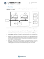
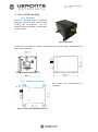
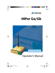
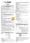
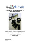
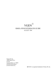
cod: pag: Hardware User Manual Veronte-HUM-v2.8.docx 1/20 cod: pag: Veronte-HUM-v2.8.docx 2/20 Table of Contents 1. OVERVIEW ..................................................................................................................................... 4 2. AIRCRAFT MOUNTING ................................................................................................................... 5 2.1.1. ENCLOSURE ................................................................................................................................ 5 2.1.2. MECHANICAL MOUNTING ............................................................................................................. 5 2.1.3. Vibration Isolation .............................................................................................................. 6 2.1.4. Location .............................................................................................................................. 6 2.1.5. Orientation ......................................................................................................................... 6 2.1.6. CONNECTOR LAYOUT.................................................................................................................... 7 2.1.7. MATING CONNECTORS ................................................................................................................. 7 2.1.8. ANTENNA INTEGRATION................................................................................................................ 7 2.1.9. PRESSURE LINES .......................................................................................................................... 8 3. ELECTRICAL .................................................................................................................................... 9 3.1.1. POWER ...................................................................................................................................... 9 3.1.2. VERONTE I/O SIGNALS ............................................................................................................... 10 3.1.3. VISION I/O SIGNALS................................................................................................................... 11 3.1.1. EXPANDER I/O SIGNALS .............................................................................................................. 12 3.1.2. JOYSTICK .................................................................................................................................. 13 3.1.3. EXTERNAL RADIO ....................................................................................................................... 14 3.1.4. IP67 VERSION .......................................................................................................................... 14 4. PERFORMANCES .......................................................................................................................... 15 5. TROUBLESHOOTING .................................................................................................................... 16 6. ANNEX 1: CONNECTOR COLOUR CODE ........................................................................................ 17 7. ANNEX 2: CONNEXION EXAMPLE – MULTICOPTER ...................................................................... 18 8. ANNEX 3: CONNEXION EXAMPLE – FIXED WING .......................................................................... 19 9. ANNEX 3: CONNEXION EXAMPLE – HELICOPTER .......................................................................... 20 Figures and Tables FIGURE 1: VERONTE FCS OVERVIEW ..................................................................................................................... 4 FIGURE 2: VERONTE AIR ..................................................................................................................................... 5 FIGURE 3: VERONTE DIMENSIONS (MM) ................................................................................................................ 5 FIGURE 4: VERONTE MOUNTING DIMENSIONS (MM) ................................................................................................ 5 FIGURE 5: ENGINE MOUNTS................................................................................................................................ 6 FIGURE 6: VERONTE & AIRCRAFT AXIS .................................................................................................................. 6 FIGURE 7: VERONTE CONNECTORS ....................................................................................................................... 7 FIGURE 8: 25-PIN MICRO D CONNECTOR FOR VERONTE AUTOPILOT I/O (4) (VERONTE CONNECTOR VIEW) ..................... 10 FIGURE 9: 25-PIN MICRO D FOR VERONTE VISION (7) (VERONTE CONNECTOR VIEW) .................................................. 11 FIGURE 10: 25-PIN MICRO D FOR VERONTE VISION (7) (VERONTE CONNECTOR VIEW) ................................................ 12 FIGURE 11: FUTABA TRAINER PORT .................................................................................................................... 13 FIGURE 12: PPM SIGNAL ................................................................................................................................. 13 FIGURE 13: EXTERNAL RADIO CONNECTOR .......................................................................................................... 14 TABLE 1: VERONTE CONNECTION PANEL................................................................................................................. 7 TABLE 2: MATING CONNECTOR TABLE .................................................................................................................. 7 TABLE 3: ANTENNA INSTALLATION ........................................................................................................................ 8 TABLE 4: PRESSURE INTAKE CONNECT ................................................................................................................... 8 TABLE 5: VERONTE POWER AND GROUND PINS ...................................................................................................... 9 TABLE 6: VERONTE I/O INTERFACE (4) ................................................................................................................ 10 TABLE 7: VISION I/O INTERFACE (7) ................................................................................................................... 11 cod: pag: Veronte-HUM-v2.8.docx 3/20 TABLE 8: EXPANDER I/O INTERFACE .................................................................................................................... 12 TABLE 9: JOYSTICK CONNECT ............................................................................................................................. 13 TABLE 10: EXTERNAL RADIO CONNECT ................................................................................................................ 14 TABLE 11: VERONTE PERFORMANCES .................................................................................................................. 15 Acronyms ADC AWG CAP DC DGPS DTS ECAP EGNOS EPWM FCS FHSS FTS GIS GND GNSS GPS GS ISM LADGPS LOS PWM PWR RF RS232 RX SMA TX UAS UAV Analog to Digital Converter American Wire Gauge Capture Module Direct Current Differential GPS Digital Transmission System Enhanced CAP European Geostationary Navigation Overlay Service Enhanced PWM Flight Control System Frequency Hopping Spread Spectrum Flight Termination System Geographical Information System Ground Global Navigation Satellite Systems Global Positioning System Ground Segment Industrial Scientific and Medical Local Area Line of Sight Pulse Width Modulation Power Radio Frequency Recommended Standard 232 Receiver SubMiniature Version A Connector Transmitter Unmanned Aerial System Unmanned Aerial Vehicle cod: pag: Veronte-HUM-v2.8.docx 4/20 1. Overview Veronte is the main element in our Flight Control System for UAS. As it can be seen in the diagram, Veronte hardware is used both in the ground segment (Ground) and onboard the UAV (either Air or Vision). Operator Operator Veronte (Air) Veronte Pipe RPAS 1 Veronte Pipe ... GIS GIS Veronte (Vision) Ground Station 1 Ground Station m RPAS 2 ... Ethernet ... Veronte (Air or Vision) Safety pilot RPAS n Veronte (Ground) Ground Segment Flight Segment Figure 1: Veronte FCS Overview Verontecontains all the electronics and sensors needed in order to properly execute all the functions needed to control the UAV. A Veronte-based FCS contains the following elements: Veronte (Air): it executes in real time all the guidance, navigation and control algorithms for the carrying airframe, acting on the control surfaces and propulsion system and processing the signals from different sensors: accelerometers, gyroscopes, magnetometer, static pressure, dynamic pressure, GPS (EGNOS/Galileo compatible). Veronte (Vision): alternative to Veronte Air. Same functionalities as Air plus video/vision capabilities. Veronte(Ground): apart from linking to other flying Veronte units and supporting manual and arcade modes with conventional joysticks, it can also control a directional antenna in order to expand the maximum range. It communicates to Veronte Pipe (software for ground segment mission management). Veronte Pipe: software for mission management at the ground segment. It monitors flying vehicles in real time and can also reproduce past missions in an offline manner. It is also the graphical user interface where commands and flight plans are produced. cod: pag: Veronte-HUM-v2.8.docx 5/20 2. Aircraft Mounting 2.1.1. Enclosure Veronte is provided using an anodizedaluminium enclosure with enhanced EMI shielding and IP protection. The total weight including a 900 MHz / 2.4GHz radio module is 190g. Figure 2: Veronte Air All Veronte versionsshare thesame enclosure.Theonly differenceisthe distributionof the connectors onthepanel. Figure 3: Veronte dimensions (mm) 2.1.2. Mechanical Mounting M4 screws mounting. Figure 4: Veronte mounting dimensions (mm) are recommended for cod: pag: Veronte-HUM-v2.8.docx 6/20 2.1.3. Vibration Isolation Although Veronte ultimately rejects noise and high-frequency modes of vibration with electronic filters, an adequate vibration isolation design can improve the performances and extend the lifetime of Veronte. Veronte can be mounted in different ways in order to reject the airframe vibration. The simplest could be achieved by just using a double-sided foam tape on the bottom side of Veronte. Other ways may use some external structure which could be rigidly attached to the airframe and softly attached to Veronte (e.g. foam, silent blocks, etc.) The user should take into account that wiring should be loose enough so vibrations may not find another way to enter the aircraft system. In cases where Veronte isolation is not viable, it is possible to use soft engine mounts. It is also recommended when there are other sensible payloads like video cameras or for high vibration engines. Figure 5: Engine Mounts 2.1.4. Location The location of Veronte has no restrictions. You only need to configureits relative position with respect to the centre of mass of the aircraft and the GPS antenna. The configuration of the location of Veronte can be easily configured usingVeronte Pipe Software. 2.1.5. Orientation The orientation of Veronte has no restrictions either. You only need to configure Veronte axes with respect to the aircraft body axes by means of a rotation matrix or a set of correspondences between axes. The configuration of the location of Veronte can be easily configured using Veronte Pipe Software. Veronte axes are printed on the box and aircraft coordinates are defined by the standard aeronautical conventions. Figure 6: Veronte & Aircraft Axis cod: pag: Veronte-HUM-v2.8.docx 7/20 2.1.6. Connector Layout Figure 7: Veronte Connectors Index Connector 1 RF antenna (SMA Jack Female) 2 GPS antenna (SMA Jack Female) 3 Ethernet (RJ-45) 4 Veronte power and I/O (Micro-D) 5 Static pressure port (Fitting 5/64in) 6 Dynamic pressure port (Fitting 5/64in) 7 Expansion board (Micro-D) 8 Composite Video (SMA Jack Female) 9 WIFI(SMA Jack Female) Table 1: Veronte connection panel For both pressure ports, mating with clamped 2mm internal diameter flexible tubing is recommended. 2.1.7. Mating Connectors Index Connector 1a/1b RF antenna (SMA Jack Female) 2 GPS antenna (SMA Jack Female) 3 Ethernet (RJ-45) Mating Connector SMA Plug female, low-loss cable is recommended (e.g. RG-174, RG-316) Antenna 900 MHz Whip, 1/2 wave Omni directional 2 dBi SMA Plug female, low loss cable is recommended (e.g. RG-174, RG-316) Active Antenna GPS: Gain min 15dB (to compensate signal loss in RF Cable) max 50dB, maximum noise figure 1.5dB, power supply 3.3V max current 20 mA RJ-45 Plug Shield, Cat 5e Receptacle 25-pin Micro-D connector Molex: 83424-9019(18in, 28AWG) Commercial Version 4a/4b Power and I/O (Micro-D) Norcomp: CCA-025-I18R152 (18in, 28AWG) Commercial Version ITT Cannon: MDM-25SH003L (18in, 26AWG) High performance version Table 2: Mating Connector Table 2.1.8. Antenna Integration The system usesthree antennas to operate that must be installed on the airframe, one for radio communications and another for GPS positioning. Here you can find some advices for obtaining the best performance and for avoiding antenna interferences. cod: pag: Veronte-HUM-v2.8.docx 8/20 Antenna Installation Maximize separation between antennas as much as possible. Keep it far away from alternators or other interference generators. Always isolate antenna ground panel from the aircraft structure. Make that the antenna is securely mounted. Always use high quality RF wires minimising the wire length. Always follow the antenna manufacturer manual. GPS Antenna Antenna top side must point the sky. Install it on a top surface with direct sky view. Never place metallic / carbon parts or wires above the antenna. It is recommended to install it on a small ground plane. Communication / video Antenna It is recommended to use Omni directional antennas. It should be installed vertically on the aircraft. It is recommended to install it on a ground plane following manufacturer indications. Place it in order to maximise the LOS with the control station. Avoid any element that could block antenna communications. Table 3: Antenna Installation 2.1.9. Pressure Lines Veronte has two pressure input lines, one for static pressure to determine the absolute pressure and one for pitot in order to determine the dynamic pressure. Absolute pressure connection on the aircraft is mandatory while pitot port can be obviated in some aircrafts, pitot port absence must be configured on Veronte Pipe software. Pressure Intake Pressure intakes must be located in order to prevent clogging. Never install pressure intakes on the propeller flow. Design pressure tubing path in order to avoid tube constriction. Static Pressure It is not recommended to use inside fuselage pressure if it is not properly vented. Pitot Tube Pitot tube must be installed facing the airflow in the direction of the “x” axis of the aircraft. It is recommended to install it near the aircraft axis in order to avoid false measures during manoeuvres. For low speed aircrafts it is recommended at least 6,3mm tubes for preventing rain obstruction. Table 4: Pressure Intake Connect It is recommended to use Embention dual Pitot tube, including both, static and pitot intakes. Caution!!Pitot pressure ranges are configurable on Veronte Hardware when placing an order, please review that selected sensor fits with aircraft speed. cod: pag: Veronte-HUM-v2.8.docx 9/20 3. Electrical 3.1.1. Power Veronte can use unregulated DC(6.5V to 36V) for a total power consumption of;4W including radio module and 10W including both, radio and Vision. Pins used for power and ground are the same for both Ground and Air/Vision configurations. Signal 4a Pin Battery Pole VIN 14 Positive (+) GND1 15 Negative (-) Table 5: Veronte Power and Ground Pins LiPo batteries between 2S and 8S can be used without regulation needs. Remaining batterycan be controlled by the internal voltage sensor and by configuring the voltage warnings on the PC application. For higher voltage installations, voltage regulators must be used. For dimensioning voltage regulators take into account that a blocked servo can activate regulator thermal protection and carry to a power cut. It is recommended to use Embention high performance UAV regulators. Caution!!Power Veronte out of the given range can cause irreversible damage to the system. Please read carefully the manual before powering the system. Veronte and servos can be powered by the same or different batteries, in case there is more than one battery on the system it is needed to ensurea singleunion of differentground. The ground signal should be isolated from other system ground references (e.g. engines). It is recommendable to use independent switches for autopilot and motor / actuators. During the system initialization, PWM signal will be fixed to low level (0V), please make sure that actuators / motor connected support this behaviour before installing a single switch for the whole system. cod: pag: Veronte-HUM-v2.8.docx 10/20 3.1.2. Veronte I/O Signals Figure 8: 25-pin Micro D connector for Veronte Autopilot I/O(4) (Veronte connector view) Signal Input Output Pin VIN Positive (+) - 14 GND1 Negative (-) - 15 PWM/GPIO 1 - 5V (12mA) 1 PWM/GPIO 2 - 5V (12mA) 2 PWM/GPIO 3 - 5V (12mA) 3 PWM/GPIO 4 - 5V (12mA) 4 PWM/GPIO 5 - 5V (12mA) 5 PWM/GPIO 6 - 5V (12mA) 6 PWM/GPIO 7 - 5V (12mA) 7 PWM/GPIO 8 - 5V (12mA) 8 PWM/GPIO 9 - 5V (12mA) 20 PWM/GPIO 10 - 5V (12mA) 21 PWM11 (FTS) - 3.3V (12mA) 16 GND2 - - 9 GND for PWM1…11 PWM/GPIO 12 (DIGIN2) 4V to 9V (on demand) 5V (12mA) 23 Note: PWM12 can be used as a digital input on demand (hardware option). GND3 - - 24 GND for PWM12 (GND DIGIN2) RS232TX - ±5V (35mA) 10 RS232RX ±25V - 11 GND4 - - 13 GND for RS232 DIGIN1 4V to 9V - 12 CMOS/TTL with interrupt capability. GND5 - - 17 GND for DIGIN1 ADCIN1 0V to 36V - 25 User-defined analog signal GND6 - - 18 GND for ADCIN1 CANHI -7V to 12V 22 CANbus interface. It supports data rates up to 1 Mbps. Recommended cable is a twisted pair with a 120Ω Zo. CANLO -7V to 12V -7V to 12V (50mA) -7V to 12V (50mA) 19 Comments 6.5 to 36V Veronte offers the option to directly drive up to 12 servos/ESCs with PWM outputs. PWM rate goes from 50Hz up to 400Hz. PWM rate is linked in pairs as follows: 1&7 2&8 3&9 4 & 10 5 & 11 6 & 12 Note: PWM11 can be used as independent logic output on demand. FTS It supports baud rates up to 115200bps. Table6: Veronte I/O interface (4) cod: pag: Veronte-HUM-v2.8.docx 11/20 3.1.3. Vision I/O Signals Figure 9: 25-pin Micro D for Veronte Vision (7) (Veronte connector view) Different connections can be used depending on your camera configuration. Signal Input Pin Comments VCC 1 POWER GND 2 POWER 3 COMMUNICATION BUS 4 COMMUNICATION BUS 5 GND FOR RS-232 RS_232_OUT RS_232_IN Output X X RS_232_GND CSI2C_DY0/D7_3.3V X X 6 CSI2C_CLK+_OUTPUT/D7 BT-656 INPUT CSI2C_DX0/D6_3.3V X X 7 CSI2C_CLK-_OUTPUT/D6 BT-656 INPUT CSI2A_DY2/D1_3.3V X 8 CSI2A_DATA1+_INPUT/D1 BT-656 INPUT CSI2A_DX2/D0_3.3V X 9 CSI2A_DATA1-_INPUT/D0 BT-656 INPUT 10 POWER 11 CSI2C_DATA0+_INPUT/RS-232 INPUT 12 CSI2C_DATA0-_INPUT/RS-232 OUTPUT 13 POWER GND CSI2C_DY1/RX232_EXTRA X CSI2C_DX1/TXC232_EXTRA X X GND D5/CSI2A_DX1 X 14 CSI2A_DATA0-_INPUT/D5 BT-656 INPUT D4/CSI2A_DY1 X 15 CSI2A_DATA0+_INPUT/D4 BT-656 INPUT D3/CSI2A_DX0 X X 16 CSI2A_CLK-_OUTPUT/D3 BT-656 INPUT D2/CSI2A_DY0 X X 17 CSI2A_CLK+_OUTPUT/D2 BT-656 INPUT 18 POWER 19 CLK BT-656 INPUT/LVDS_A INPUT X 20 CAM RESET OUTPUT/LVDS_B INPUT CAM_SCCB X 21 I2C SIGNAL CAM_VBUS/SHUTTER (USB) X 22 USB POWER/SHUTTER OUTPUT GND PCLK\LVDS_A X CAM_RESET/LVDS_B X CAM_ID/SCL (USB) X X 23 USB ID/I2C CLK CAM_DP/SDA (USB) X X 24 USB DATA_P/I2C DATA CAM_DM/SCCB (USB) X X 25 USB DATA_M/I2C SIGNAL Table7: Vision I/O interface (7) Caution!!Veronte Vision has an independent power input. It is required when the Veronte power source is under 10 V. cod: pag: Veronte-HUM-v2.8.docx 12/20 3.1.1. Expander I/O Signals Figure 10: 25-pin Micro D for Veronte Expander (7) (Veronte connector view) Different connections can be used depending on theselected hardware configuration. Signal Input Output GND Pin Comments 1 RS-232_A_TX X RS-232_A_RX X 2 3 GND 4 GND 5 PWM5/ECAP3 X X 6 Hardware option, not selectable on SW PWM6/ECAP4 X X 7 Hardware option, not selectable on SW PWM7 X 8 PWM8 X 9 GND 10 ANALOGIC_UNIPOLAR_1/ANALOGIC_DIF_1+ X 11 Hardware option, not selectable on SW ANALOGIC_UNIPOLAR_2/ANALOGIC_DIF_1- X 12 Hardware option, not selectable on SW ANALOGIC_UNIPOLAR_3/ANALOGIC_DIF_2+ X 13 Hardware option, not selectable on SW RS-232_B_TX X RS-232_B_RX X 14 15 GND 16 17 Only for configurations with 2 or more expansion modules X 18 Hardware option, not selectable on SW X X 19 Hardware option, not selectable on SW PWM3/ECAP1/ARINC_RX_B_OUT X X 20 Hardware option, not selectable on SW PWM4/ECAP2/ARINC_RX_A_OUT X X 21 Hardware option, not selectable on SW OPTIONAL POWER INPUT X PWM1/ECAP6/ARINC_TX_A_OUT X PWM2/ECAP5/ARINC_TX_B_OUT GND 22 ANALOGIC_UNIPOLAR_4/ANALOGIC_DIF_2- X 23 Hardware option, not selectable on SW ANALOGIC_UNIPOLAR_5/ANALOGIC_DIF_3+ X 24 Hardware option, not selectable on SW ANALOGIC_UNIPOLAR_6/ANALOGIC_DIF_3- X 25 Hardware option, not selectable on SW Table 8: ExpanderI/O interface Caution!!Veronte Expander has an independent power input. It is required only for configurations with more than one expansion module. cod: pag: Veronte-HUM-v2.8.docx 13/20 3.1.2. Joystick To connect the joystick to the system, use the DIGIN1port on Veronte Ground connected to the radio trainer port. Veronte is compatible with standard PPM signals, Futaba radios between 8 and 12 channels are recommended. Figure 11: Futaba Trainer Port Signal Veronte Radio Comments PPM DIGIN1 PPMOUT GND GND5 Ground Table 9: Joystick Connect Figure 12: PPM Signal As default, channel 8 is reserved for manual / auto switch. High level is used for automatic flight and low level for manual control. This channel can be configured on Veronte Pipe. Caution!!PPM signal must be into the PPM ranges given with voltage above 4V. Some joysticks may need an adaptationboard, please ask our team to check compatibility. Micro D connector for CS is provided with 3.5mm stereo plug connector as follows: DIGN GND cod: pag: Veronte-HUM-v2.8.docx 14/20 3.1.3. External Radio Veronte is also offered with a RS-232 connector to be used with an external radio. Figure 13: External Radio Connector The mating radio connector for this configuration is: Phoenix Contact - 1681172 Signal Input Output Pin RS232 Veronte TX - ±5V (35mA) 1 RS232 Veronte RX ±25V - 3 - - 4 RS232 Veronte GND Comments Table 10: External Radio Connect 3.1.4. IP67 Version IP67 autopilot is supplied with no 25 pin micro D connector in order to ensure highest environment protection. It is supplied with individual wire leads as follow. PIN Colour PIN Colour 1 Black 14 Broun / White 2 Broun 15 Red / White 3 Red 16 Orange / White 4 Orange 17 Green / White 5 Yellow 18 Blue / White 6 Green 19 Violet / White 7 Blue 20 Red / Black 8 Violet 21 Orange / Black 9 Grey 22 Yellow / Black 10 White 23 Green / Black 11 Pink 24 Grey / Black0 12 Light green 25 Pink / Black 13 Black / White cod: pag: Veronte-HUM-v2.8.docx 15/20 4. Performances Variable Value Weight (900MHz /2.4GHz radio included) 190g Power Input 6.5V to 36V (4W) (10W with expansion board) Minimum Temperature -40ºC Maximum Temperature +55ºC Max. Internal Temperature +85ºC Minimum Pressure 15kPa Maximum Pressure 115kPa Maximum Dynamic Pressure 10kPa IP54 Acceleration Limits (3 axes) ±6g Angular Velocity Limits (3 axes) 4 ±300deg/s Magnetic Field Limits (3 axes) Datalink 2 3 Protection Rating GPS 1 5 ±6Gauss 12 channels, DGPS EGNOS, LADGPS 902-928MHz FHSS DTS / Range 96km / 115kbps 2.4 to 2.483 GHz ISM Band / Range 32km / 115kbps X-868 MHz ISM / Range 40km / 4 Kbps X-902 to 928 MHz / Range 45km / 10 kbps Table11: Veronte performances 1 No convection, ask for increased limits (up to 71ºC) Ask for increased limits (up to 50kPa) 3 Ask for increased limits (up to IP67) 4 Limit for sustained maneuvers. Transitional higher accelerations are possible (e.g. catapult launch). Ask for increased limits. 5 Limit for sustained maneuvers. Transitional higher angular velocities are possible. Ask for increased limits. 2 cod: pag: Veronte-HUM-v2.8.docx 16/20 5. Troubleshooting I´m having problems with the GPS signal o Reduce noise level on the GND connection on the autopilot by connecting the autopilot GND directly to the battery GND, avoiding intermediate connections and solders. cod: pag: 6. Annex 1: Connector Colour Code Micro-D connector Molex 83424-9019 Veronte-HUM-v2.8.docx 17/20 cod: pag: Veronte-HUM-v2.8.docx 18/20 7. Annex 2: Connexion example – Multicopter Pin 14 – V+ Battery Pin 15 – VPin1 – CH1 ESC 1 Pin 2 – CH2 ESC 2 Pin 3 – CH3 ESC 3 Pin 4 – CH4 ESC 4 Static pressure GPS antenna RF antenna cod: pag: Veronte-HUM-v2.8.docx 19/20 8. Annex 3: Connexion example – Fixed wing Pin 14 – V+ Pin 15 – V- Battery Pin1 – CH1 Aileron right Pin 5 – CH5 Aileron left Pin 2 – CH2 Elevator Pin 4 – CH4 Rudder Pin 6 – CH6 Gimbal Tilt Pin 7 – CH7 Gimbal Pan Pin 3 – CH3 Pin 13 – GND Static pressure ESC DC/DC Motor GPS antenna RF antenna cod: pag: Veronte-HUM-v2.8.docx 20/20 9. Annex 3: Connexion example – Helicopter Pin 14 – V+ Pin 15 – V- Battery Pin1 – CH1 Plate NW Pin 5 – CH5 Plate S Pin 2 – CH2 Plate NE Pin 4 – CH4 Tail Pin 12 – ECAP RPM Pin 3 – CH3 Pin 9 – GND Static pressure ESC DC/DC Motor Dynamic pressure GPS antenna RF antenna