1
THELlGHT Luminary for cine and TV, S.L.
www.thelight.com.es
2011
®
Copyright ll-lELk3HT. An rights reserved.
28
WARRANTY
THELIGHT high power LED light equipments are guaranteed to be free from defects in workmanship
and parts in a warranty period of one (1) year from the date of purchase. Defects that occur within
this warranty period, under normal use and care will be repaired or replaced at THELlGHT discretion,
solely at our option with no charge for parts or labor.
In the event of the equipment malfunction, contact the dealer from which you purchased the product.
Please note that you will be not be reimbursed for the cost of bringing the equipment to the
THELIGHTRepair Center.
THELlGHT reserves the right to replace the product or relevant part with the same or equivalent
product or part, rather than repair it. Where a replacement is provided the products or part
replaced becomes the property of THELIGHT.THELlGHT may replace parts with refurbished parts.
Replacement of the product or a part does not extend or restart the Warranty period.
Returns or exchanges from the customers will be accepted within 1 5 days of delivery and will not
include the actual shipping costs. ltem[s) must be in original packaging and condition, must not be
assembled, and must include its original user manual.
This warranty does not cover any damage resulting from:
Failure to follow the instructions in the instruction manual;
Repair, modification or overhaul not conducted by any authorized THELlGHTpersonnel.
Fire, natural disaster, act of God, lightning, abnormal voltage, etc;
Submergence in water [flooding), exposure to alcohol or other beverages, infiltration
of sand or mud, physical shock, or dropping of the equipment and other unnatural causes.
This warranty only applies to the lamp head and the Control Unit and not to the accessories, such as
the diffuser or barn doors, nor does it apply to the fuses and other consumables provided.
Any consequential damages arising from failure of the equipment, such as expenses incurred in
taking pictures or recording images or loss of expected profit, will not be reimbursed whether they
occur during the warranty period or not.
Parts essential to the servicing of the light equipment [that is, components required to maintain the
functions and quality of the fixture) will be available for a period of five years after the product is
discontinued.
THELlGHTLuminary for cine and tv, S.L.
www.thelight.com.es
The total or partial reproduction
of this guide is prohibited without the espress written permission
TI-EUGHT technology;s
protected under Spanish licenso lows with intemational
patents pending.
Information and speciticetions in this document
ere subjoct to changc without notice.
2011 O"J
Copyright lHEUGI-IT. All rights reserved.
of THBJGI-fT.
26
SAFETY PRECAUTIONS
Various symbols are used throughout this instruction manual and on the product to prevent physical
harm to you or other people and damage to property.
The symbols and their meanings are explained below.
~
&
Warning
Danger
Possible risk of injury or damage to equipment
This symbol indicates the risk of electric shock or fire danger that could
result in injury or damage to equipment.
This equipment has been checked and meets the requirements
of general safety for electronic
devices. These requirements
are specified to provide a reasonable
protection
against
electromagnetic interferences when the equipment is used in commercial environments.
This equipment generates, uses and can emit waves of radio frequency, and if not properly used
following the instructions of this manual can produce interferences in radio communications. The use
of this equipment in residential areas can produce interferences, the user will be the only responsible
of correcting them.
CAUTION: Though the light generated by LEO does not produce any heat, for what his use turns out
to be very comfortable for the actors, the lamp head acts as a heat sink through its back part.
Surface can reach a temperature
between the 50 "C and the 80 "c. Please use protective gloves if
you touch the lamp head at the heat sink.
e:
00 not attempt to open any of the device or component housings. To
reduce the risk of electric shock, do not remove lamp head or Control
Unit cover. No user-serviceable parts inside. Maintenance and repair
work to be carried out only by THELlGHTService Center.
Danger
00 not cover the aluminium lamp head heat sink while using it. Proper
ventilation must be provided. Avoid exposing the lamp head to the heat
radiation of other light fixtures.
The lamp head is equipped with high power LEos. Due to their high lightoutput intensity don't stare directly into the light source.
~
Warning
In order to protect against risk of electric shock, the installation should be
properly grounded. Defeating the purpose of the grounding type plug will
expose you to the risk of electric shock.
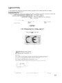
Marking
CE
4
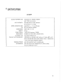
REGULATIONS
This equipment is designed to meet the following regulations
and safety standards
for battery
powered technology equipment:
ENVINRONMENTAL
THElIGHT devices are certified and intended for indoor use [lamp head IP21. VOC Control Unit IP41 J
LAMP HEAD OPERATION TEMPERATURE
from -20· to +30· C
CONTROL UNIT OPERATION TEMPERATURE
from -20· to +50· C
OPERATING HUMIDITY from 30 to 90% RH non condensing
FUSE 2 x 2.5 A
'.J
CE
tstpro
rtllit ,,'
M,;>, THWGHr
~010· Ii'O
1~'''''f.
Dat~· 2';
,u· 20~O
Se":,Jf!,!'
$-ft':
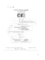
REPORT
ELECTROMAGNETIC
COMPATIBILITY
Tellt Laboratory, CE mark
TESTS AND MEASURES REQUESTED,
OfMC1'fVl>
:mO,(itIlB/C.E €!I!t;;.1t{'J,",,~<'I"11e- C(lf!':ti'~I1\'::ll\~
r£ MC)
STA.PA~O,
il!:.G) EN £j19tti<6.!
~
rleC:~a~t:t.cN·'10:ltit){l't)
('~
ntn!~ty lt~.~
r.t('~'4ii!1 t"'1 !~~lt'~:n.V'Y
'Igm lO::i<i'filry
life; r- N e~ 00.":1-6.3:'005 E~I!".;!r.Ql1"!~f'!!~l.r~
(:1:',..,ptl:~t>II~¥.~tf\(:
p,,: $~~tY,:I"td ft"t.~AofVlft',fl';
EN ~fj'4~~ 1 ", ~ l t2Xe .•:)l} Rll:d:o Ele~neSDt{1n1'!'l r.-o.'lfC1km {t - e CH! 13IlOO'!
l,iEt}!:N 6lm~"2
»eOllM lO0t3 l'rtml;1ili'e t:1)':(<!~ft'-\i'llll;Nl~ 4 ~ Y~l
;,[C; E:Ne4rn)'·~·:\19qF;A2 100a \fb!!tt::)':' f!:Jd1.I~rrt~ ond FI,,:kflr,1 ;; M""'lJ.
U.~;·EN §~Ot.5 1«)'1'4 A,1 2OC$,,1.2. ~~
:;Mi ~ !6')A<Cftt('--" o;h"l09 ilM t\OH~1 ~ltihll~
(CI!{P'.
f
1!;"7tf.B)
~:--;:;~-.-"-\
i\...
r J 0 .;...~
!....-;,
".!\>~<""_t~"
~t.'~~;-r<t""r.rL"'~~:"";:':Y' ""~.~
~
A.IJ ea \(t.~~r;1!
C~1O.,!-ItrrChi91"
"'~{!~f.lM;_r;~I!-IOO1~\
V;!;>'!",,~ M~~~lON.f.
(tn~~S$f1
~O""t" ~~~ ,~;:O; ,~,,.. ~,. .•"~lth!~,x:..;~1
\;0
~~~'~!'
O')li,"ioW!.\I'~'.:eo:;,fl"'
"'\1 'I~
24
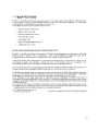
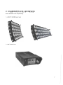
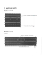
1. MAIN FEATURES
BLIGHT/ 4LoNG are LED panel shousing a total of 144 high power LED [BLIGHT]/ 19B high power
LED [4LDNG). They have been specially designed and their colorimetry calibrated for professional
photography, cinematography and television industry use.
THELlGHTluminaries main innovative features are:
Variable Colour Temperature
Stable colour dimming
Green/magenta
bias control
Very high light output
Low power draw
High CRI digitally calibrated light
Lightweight lamp head
NOTE ABOUT MEASURING
COLOUR TEMPERATURE
[CCT]
BLIGHT/ 4LoNG incorporate the innovative THELlGHTtechnology based on high power LED triplets
Warm White + White + Green + fresnel lens + CPU control software to obtain the wide range of
calibrated colour temperatures
combined with a high colour rendering index CCT.
We must remark that colour meters in use today are designed for a full spectrum source such as
incandescent
lights and therefore cannot be used to accurately read the correlated
colour
temperature [CCT] of the light emitted by THELlGHTand other LEO light fixtures.
The eventual diversions to green display as CC1 OM or CC15M in hand held colour meters are due to
these unaccuracy on reading of the light emitted by LED and must not be considered.
THELlGHTguarantees pure white light and correct colorimetry of the light delivered by its high power
LED luminaries which have been calibrated in laboratory according to CIE 13.3-1995
international
standards for measurement of the CRI and chromatic coordinates [x, and CIE-1931].
The reliability of this digital equipment is supported by the calibration THELlGHT has made in
laboratory by spectrophotometer,
which precision is half-yearly calibrated according to the National
Institute of Standards [NIST] of the United States and of the Physikalisch-Technische Bundesanstalt
[PTB] of Germany.
In order that the advanced THELlGHT luminaries could be used together with other light sources,
THELlGHThas accurately calibrated both the CCT and the chromatic coordinates to match them with
traditional light sources following tungsten and daylight standards.
The digital Control Unit allows a further and precise green/magenta
of colour temperatures.
correction along the whole scale
6
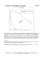
GCD
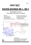
PHOTOMETRICS
...-..
-~, ~
""~,
,"'-
..
.•~,. Ut •.•. ",
"""""~~"-~"'~-~~~~'''~
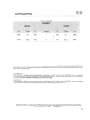
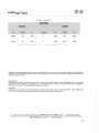
24 fps / 500 ASA
6LIGHT~
3200k
5600K
LUx
F-8top
Fe
9000
16.7
836
1100
5,6.7
102
meters
3
Fe
F-Stop
Lux
632
16.3
6800
78
5,6.3
840
Readings made with scanning spectrometer at stable temperature. Control Unit set at maximum light intensity [Turbo On
and dimmer at 9 setting). lamp head at standard flat setting and measurement instrument positioned perpendicular over
surface center.
the luminary
CAUBRATkJN
The Instrument Systems scanning spectrometer,
model Spectra 320. serial number 30932004, with its accessory
Institute of Standards [NISTJ and the German
TOP-10o has been calibrated according to the United States National
Physikalisch-Technische
Bundesanstalt
(PTB] standard references.
ACCURACY
The Instrument Systems scanning spectrometer.
model Spectro 320. serial number 30932004.
lOP-1 00 has an imprecision over the spectral radiometric results delivered lower than 1%•.
with its accessory
~e~!~.~,?tion.sSUbjDC~
t.o.~.~I;'~ge~.~.'!':.,~.o.tic~:.~
. ~G1ir.tec.hnology
I!>pr.o~~~ ..~tl~er Sp.~':lis~.~cena~Ia~ ~Jf]~~'!l.~.~.o.f.J.~.I.p.~.~ry!S
p.~tldi~g.
TI-fiIGHT luminary for clne and tv, S.L
www.thelighl.com.es
22
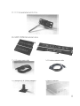
1 x Quick link swivel-ball head with 3/B"
2 x 6UGHT
I 4LONG
1 x 2,5 meters
Removable
barn doors
power cable
1 X HexagonaI5/B"
[16mm)
pin
1 x 2.5 meters
baby spud
extension
cable
1 X Quick link diffusser
8
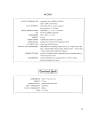
4LONG
COLOURTEMPERATURE
adjustable from 2BooK a B500K
(with 1ooK increments)
LIGHTINTENSITY
dimmable with no colour deviation
(increments of 1/2 stop)
GREEN/MAGENTA BIAS
adjustable
CRI
+/-
1/4 Y 1/8 steps
90 from 2900K a 6500K
DIMENSIONS
622x207x71
mm
4,4 kg
WEIGHT
POWER DRAW
185W 30V (maximum 220W)
BEAM ANGLE
variable from 3D" to 65" (standard 35")
LED RATEDLIFE
more than 50.000 hours
THELlGHTLEDTECHNOLOGY
UME (Minimum Emitting Unit) made up of. 3 high power LED
with a selected BIN: Warm white, White, Green + fresnellens
+ CPU control with THELlGTHsoftware.
RIGGINGOPTIONS
quick link swivel-ball head, adjustable yoke, adjustable yoke to
mount up to four units
ACCESSORIES quick link diffuser box, hexagonal 5/8" (16mm ) baby
spud,removable barn doors
I Control
Unit I
DIMENSIONS 334 x 173 x 87 mm
WEIGHT 2,7 kg
POWER SUPPLY Universal 90-264 VAC
INPUT FREQUENCY 50/6oHz
OUTPUT FREQUENCY 20KHz
FUSE 2 x 2,5 A
20
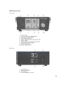
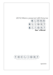
VAC Control Unit
Front view
6
1
2
3
4
5
6
7
8
9
10
2
3
7
8
4
5
10
Power switch
Colour temperature digital display
Intensity level digital display
Turbo status blue LED
Green/ magenta offset status green LED
Power output
Colour temperature adjustment buttons
Intensity adjustment buttons
On/off turbo button
Green/ magenta knob
Rear view
1.
2.
3.
4.
1
2
3
4
XLR DMX input
Mains power input
XLR DMX out
Fuse receptacle [2 x 2,5AJ
10
&
,
•
Wa'
rrunq
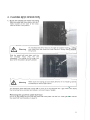
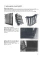
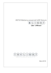
Quick link diffuser
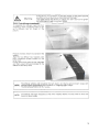
If there is too much friction on the barn doors or they even become
stuck do not force them since they might get damage.
Just lightly loosen the knobs to release the barn doors and tighten
the knobs again to get the wished friction.
installation
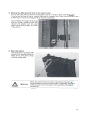
To assemble the diffuser insert the four
magnets in their respective holes to setup a diffusion box as shown in the
picture.
~<.
•
Position the lamp head in its standard flat
setting.
Align the top diffuser box magnets with
their respective screws located on the
lamp head.
Do the same thing with the low magnets
and their power will automatically fix the
diffuser to the lamp head.
NOTE:
NOTE'
,
The diffuser softens and broadens the light beam. yet retains general
minimal colour temperature
shift. Excellent for softening harsh edges.
The transmission lost is 2/3 of a stop.
beam shape with
The diffuser has been designed so that when installed allows the lamp head to bend and
focus the beam angle.
18
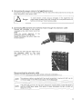
2. Connecting
the power cable to the VAC Control Unit
Connect the power cable to the plug located in the rear side of the VDC Control Unit. Connect the
power plug with a mains power outlet.
e:
3. Connecting
Danger
To avoid electric shocks and/or damages in the equipment the
power switch located at the VAC Control Unit front panel must be off
before connecting or disconnecting cables.
VAC Control Unit and lamp head through
the extension
cable
Connect the connector in the circular
receptecle at the VAC Control Unit front
panel.
Verity the correct alignment of the
connectors before inserting them.
Rotete the locking ring until it clicks into
the lock position.
Connect the same way the other end of
the extension cable in the input
receptacle coming out from the lamp
head.
Disconnecting
the extension
cable
Grab the connector firmly. turn the ring to unlock it and pull to extract it.
NOTE' The extension cable is provided with two equal connectors in every end: both can be
. connected either in the VAC Control Unit or in the lamp head.
THELlGHTVAC Control Unit has been designed to supply power to both the BLIGHT
NOTE: and the 4LONG lamp heads. With either of these connected the light emitted will
always be correct.
12
S.DMX 512 CONTROL
THELlGHTmains power lightning fixtures have been designed for a full OMX control from the Spin
OMX port on the back of the VAC Control Unit.
Connect the OMX cable coming from your console into the OMX IN male connector located at the
back fo the VAC Control Unit. Beside the OMX IN there is also a OMX OUT connector to daisy.chain
fixtures.
Adressing channels
Push both + and - COLORTEMPERATUREbuttons at the same time and then switch on the power
button. Wait a few seconds for the three digital displays to blink.
Now you can define the start address. To do so just push the + or - DIMMER buttons to increase or
decrease the first fixture address. Once you have chosen the desired address number push the
TURBO button to save th e selection.
Keep in mind the following points regarding OMX control:
THELlGHT OMX protocol uses 5 channels per fixture
The first fixture to be controlled should be set to OMX address 001 and it will automatically
use the following four channels.
If you wish to control several THELlGHTfixtures at the same values you will have to set them
to the same address.
If you wish to control several THELlGHT fixtures independently you will have to offset their
address by 5 channels. Example:
fixture1 address 001 - fixture2 address 006 - fixture3 address 011
DMXMDdes
When you connect your console to the VAC Control Unit you will have to control modes over
THELlGHTfixtures through 5 channels.
Channel 1 [start address] defines control mode:
1. THELlGHT MDde [channel 1 fader at 0%]
The VAC Control Unit display will be on and will show the values selected from the console.
The following channels will perform as follows:
Channel 2 [start address + 1]- TURBO
fader at 0%
Turbo Off
fader at 100%
Turbo On
Maximum light output at any colour temperature
Canal 3 [start address + 2]- COLOURTEMPERATURE
Canal 4 [start address + 3]- DIMMER
Canal 5 [start address + 4]- GREEN/MAGENTA BIAS correction
fader at 50%
standard position [green/magenta at 0]
fader at 25%
-1/B Green
fader at 0%
- 1/4 Green
fader at 75%
+1/8 Green
fader at 100%
+1/B Green
2. INDIVIDUAL MDde [channel 1 fader at 100%]
The VAC Control Unit display will be off.
The Individual mode lets you bypass the THELlGHT software to freely control any of the three
LEOs:Warm White, White and Green.
The following channels will perform as follows:
Channel 2 [start address + 1] - WARM WHITE
Channel 3 [start address + 2] - WHITE
Channel4 [start address + 3]- GREEN
Channel 5
- no use
16
5. DIGITAL ADJUSTMENTS
The VAC Control Unit doubles as power supply and digital remote controller of the following light
parameters through its programmed CPU:
Calibrated Colour Temperature variation
Stable colour dimming
Green/magenta bias control
Turning the Power On/Off
Turn on the equipment by switching the power button towards the I position. Switch the power button
towards 0 position to turn it off.
The light settings always remain stored when the VAC Control Unit is powered off.
&
Danger
Both the lamp head and the VAC Control Unit are electrically protected
against power failures but to avoid possible electric shocks and/or
equipment damages make sure the power switch located at the VAC
Control Unit front panel will be off before connecting or disconnecting
cables.
In case of extreme over tension replace the 5mm 2,5Ah fuses from inside
the fuseholder located at VAC Control Unit back. [see picture on page 9J
If a power failure would happen or the cables would be accidentally disconnected the VAC
Control Unit would entry on Error mode and the number B would show in the digital
NOTE: display.
To reset the equipment and resume the light values turn the switch power off, connect
the cables and switch on the power button.
CalOR TEMPERATURE Variation
Colour temperature can be easily increased or reduced through the +/: buttons located at the VAC
Control Unit front panel. Above them a digital display indicates at all times the selected colour
temperature. The value 3.2 corresponds to 3200K and the value 3.3 to 3300K and so on.
Push the + button to increase colour temperature or push the - button to decrease it. If you keep
pushed any of the buttons the you will get a continuous variation.
NOTE' Every push on the buttons will increase or decrease the colour temperature in calibrated
, increments of 100 Kelvin.
TURBO
By activating the TURBO button [a blue LED lights up on the screen of the Control UnitJ maximum
light output is achieved in the colour temperature selected and the value 9 will appear on the
dimmer display.
14
S.DMX 512 CONTROL
THELlGHTmains power lightning fixtures have been designed for a full OMX control from the Spin
OMX port on the back of the VAC Control Unit.
Connect the OMX cable coming from your console into the OMX IN male connector located at the
back fo the VAC Control Unit. Beside the OMX IN there is also a OMX OUT connector to daisy.chain
fixtures.
Adressing channels
Push both + and - COLORTEMPERATUREbuttons at the same time and then switch on the power
button. Wait a few seconds for the three digital displays to blink.
Now you can define the start address. To do so just push the + or - DIMMER buttons to increase or
decrease the first fixture address. Once you have chosen the desired address number push the
TURBO button to save th e selection.
Keep in mind the following points regarding OMX control:
THELlGHT OMX protocol uses 5 channels per fixture
The first fixture to be controlled should be set to OMX address 001 and it will automatically
use the following four channels.
If you wish to control several THELlGHTfixtures at the same values you will have to set them
to the same address.
If you wish to control several THELlGHT fixtures independently you will have to offset their
address by 5 channels. Example:
fixture1 address 001 - fixture2 address 006 - fixture3 address 011
DMXMDdes
When you connect your console to the VAC Control Unit you will have to control modes over
THELlGHTfixtures through 5 channels.
Channel 1 [start address] defines control mode:
1. THELlGHT MDde [channel 1 fader at 0%]
The VAC Control Unit display will be on and will show the values selected from the console.
The following channels will perform as follows:
Channel 2 [start address + 1]- TURBO
fader at 0%
Turbo Off
fader at 100%
Turbo On
Maximum light output at any colour temperature
Canal 3 [start address + 2]- COLOURTEMPERATURE
Canal 4 [start address + 3]- DIMMER
Canal 5 [start address + 4]- GREEN/MAGENTA BIAS correction
fader at 50%
standard position [green/magenta at 0]
fader at 25%
-1/B Green
fader at 0%
- 1/4 Green
fader at 75%
+1/8 Green
fader at 100%
+1/B Green
2. INDIVIDUAL MDde [channel 1 fader at 100%]
The VAC Control Unit display will be off.
The Individual mode lets you bypass the THELlGHT software to freely control any of the three
LEOs:Warm White, White and Green.
The following channels will perform as follows:
Channel 2 [start address + 1] - WARM WHITE
Channel 3 [start address + 2] - WHITE
Channel4 [start address + 3]- GREEN
Channel 5
- no use
16
2. Connecting
the power cable to the VAC Control Unit
Connect the power cable to the plug located in the rear side of the VDC Control Unit. Connect the
power plug with a mains power outlet.
e:
3. Connecting
Danger
To avoid electric shocks and/or damages in the equipment the
power switch located at the VAC Control Unit front panel must be off
before connecting or disconnecting cables.
VAC Control Unit and lamp head through
the extension
cable
Connect the connector in the circular
receptecle at the VAC Control Unit front
panel.
Verity the correct alignment of the
connectors before inserting them.
Rotete the locking ring until it clicks into
the lock position.
Connect the same way the other end of
the extension cable in the input
receptacle coming out from the lamp
head.
Disconnecting
the extension
cable
Grab the connector firmly. turn the ring to unlock it and pull to extract it.
NOTE' The extension cable is provided with two equal connectors in every end: both can be
. connected either in the VAC Control Unit or in the lamp head.
THELlGHTVAC Control Unit has been designed to supply power to both the BLIGHT
NOTE: and the 4LONG lamp heads. With either of these connected the light emitted will
always be correct.
12
&
,
•
Wa'
rrunq
Quick link diffuser
If there is too much friction on the barn doors or they even become
stuck do not force them since they might get damage.
Just lightly loosen the knobs to release the barn doors and tighten
the knobs again to get the wished friction.
installation
To assemble the diffuser insert the four
magnets in their respective holes to setup a diffusion box as shown in the
picture.
~<.
•
Position the lamp head in its standard flat
setting.
Align the top diffuser box magnets with
their respective screws located on the
lamp head.
Do the same thing with the low magnets
and their power will automatically fix the
diffuser to the lamp head.
NOTE:
NOTE'
,
The diffuser softens and broadens the light beam. yet retains general
minimal colour temperature
shift. Excellent for softening harsh edges.
The transmission lost is 2/3 of a stop.
beam shape with
The diffuser has been designed so that when installed allows the lamp head to bend and
focus the beam angle.
18
VAC Control Unit
Front view
6
1
2
3
4
5
6
7
8
9
10
2
3
7
8
4
5
10
Power switch
Colour temperature digital display
Intensity level digital display
Turbo status blue LED
Green/ magenta offset status green LED
Power output
Colour temperature adjustment buttons
Intensity adjustment buttons
On/off turbo button
Green/ magenta knob
Rear view
1.
2.
3.
4.
1
2
3
4
XLR DMX input
Mains power input
XLR DMX out
Fuse receptacle [2 x 2,5AJ
10
4LONG
COLOURTEMPERATURE
adjustable from 2BooK a B500K
(with 1ooK increments)
LIGHTINTENSITY
dimmable with no colour deviation
(increments of 1/2 stop)
GREEN/MAGENTA BIAS
adjustable
CRI
+/-
1/4 Y 1/8 steps
90 from 2900K a 6500K
DIMENSIONS
622x207x71
mm
4,4 kg
WEIGHT
POWER DRAW
185W 30V (maximum 220W)
BEAM ANGLE
variable from 3D" to 65" (standard 35")
LED RATEDLIFE
more than 50.000 hours
THELlGHTLEDTECHNOLOGY
UME (Minimum Emitting Unit) made up of. 3 high power LED
with a selected BIN: Warm white, White, Green + fresnellens
+ CPU control with THELlGTHsoftware.
RIGGINGOPTIONS
quick link swivel-ball head, adjustable yoke, adjustable yoke to
mount up to four units
ACCESSORIES quick link diffuser box, hexagonal 5/8" (16mm ) baby
spud,removable barn doors
I Control
Unit I
DIMENSIONS 334 x 173 x 87 mm
WEIGHT 2,7 kg
POWER SUPPLY Universal 90-264 VAC
INPUT FREQUENCY 50/6oHz
OUTPUT FREQUENCY 20KHz
FUSE 2 x 2,5 A
20
1 x Quick link swivel-ball head with 3/B"
2 x 6UGHT
I 4LONG
1 x 2,5 meters
Removable
barn doors
power cable
1 X HexagonaI5/B"
[16mm)
pin
1 x 2.5 meters
baby spud
extension
cable
1 X Quick link diffusser
8
GCD
PHOTOMETRICS
...-..
-~, ~
""~,
,"'-
..
.•~,. Ut •.•. ",
"""""~~"-~"'~-~~~~'''~
24 fps / 500 ASA
6LIGHT~
3200k
5600K
LUx
F-8top
Fe
9000
16.7
836
1100
5,6.7
102
meters
3
Fe
F-Stop
Lux
632
16.3
6800
78
5,6.3
840
Readings made with scanning spectrometer at stable temperature. Control Unit set at maximum light intensity [Turbo On
and dimmer at 9 setting). lamp head at standard flat setting and measurement instrument positioned perpendicular over
surface center.
the luminary
CAUBRATkJN
The Instrument Systems scanning spectrometer,
model Spectra 320. serial number 30932004, with its accessory
Institute of Standards [NISTJ and the German
TOP-10o has been calibrated according to the United States National
Physikalisch-Technische
Bundesanstalt
(PTB] standard references.
ACCURACY
The Instrument Systems scanning spectrometer.
model Spectro 320. serial number 30932004.
lOP-1 00 has an imprecision over the spectral radiometric results delivered lower than 1%•.
with its accessory
~e~!~.~,?tion.sSUbjDC~
t.o.~.~I;'~ge~.~.'!':.,~.o.tic~:.~
. ~G1ir.tec.hnology
I!>pr.o~~~ ..~tl~er Sp.~':lis~.~cena~Ia~ ~Jf]~~'!l.~.~.o.f.J.~.I.p.~.~ry!S
p.~tldi~g.
TI-fiIGHT luminary for clne and tv, S.L
www.thelighl.com.es
22
1. MAIN FEATURES
BLIGHT/ 4LoNG are LED panel shousing a total of 144 high power LED [BLIGHT]/ 19B high power
LED [4LDNG). They have been specially designed and their colorimetry calibrated for professional
photography, cinematography and television industry use.
THELlGHTluminaries main innovative features are:
Variable Colour Temperature
Stable colour dimming
Green/magenta
bias control
Very high light output
Low power draw
High CRI digitally calibrated light
Lightweight lamp head
NOTE ABOUT MEASURING
COLOUR TEMPERATURE
[CCT]
BLIGHT/ 4LoNG incorporate the innovative THELlGHTtechnology based on high power LED triplets
Warm White + White + Green + fresnel lens + CPU control software to obtain the wide range of
calibrated colour temperatures
combined with a high colour rendering index CCT.
We must remark that colour meters in use today are designed for a full spectrum source such as
incandescent
lights and therefore cannot be used to accurately read the correlated
colour
temperature [CCT] of the light emitted by THELlGHTand other LEO light fixtures.
The eventual diversions to green display as CC1 OM or CC15M in hand held colour meters are due to
these unaccuracy on reading of the light emitted by LED and must not be considered.
THELlGHTguarantees pure white light and correct colorimetry of the light delivered by its high power
LED luminaries which have been calibrated in laboratory according to CIE 13.3-1995
international
standards for measurement of the CRI and chromatic coordinates [x, and CIE-1931].
The reliability of this digital equipment is supported by the calibration THELlGHT has made in
laboratory by spectrophotometer,
which precision is half-yearly calibrated according to the National
Institute of Standards [NIST] of the United States and of the Physikalisch-Technische Bundesanstalt
[PTB] of Germany.
In order that the advanced THELlGHT luminaries could be used together with other light sources,
THELlGHThas accurately calibrated both the CCT and the chromatic coordinates to match them with
traditional light sources following tungsten and daylight standards.
The digital Control Unit allows a further and precise green/magenta
of colour temperatures.
correction along the whole scale
6
REGULATIONS
This equipment is designed to meet the following regulations
and safety standards
for battery
powered technology equipment:
ENVINRONMENTAL
THElIGHT devices are certified and intended for indoor use [lamp head IP21. VOC Control Unit IP41 J
LAMP HEAD OPERATION TEMPERATURE
from -20· to +30· C
CONTROL UNIT OPERATION TEMPERATURE
from -20· to +50· C
OPERATING HUMIDITY from 30 to 90% RH non condensing
FUSE 2 x 2.5 A
'.J
CE
tstpro
rtllit ,,'
M,;>, THWGHr
~010· Ii'O
1~'''''f.
Dat~· 2';
,u· 20~O
Se":,Jf!,!'
$-ft':
REPORT
ELECTROMAGNETIC
COMPATIBILITY
Tellt Laboratory, CE mark
TESTS AND MEASURES REQUESTED,
OfMC1'fVl>
:mO,(itIlB/C.E €!I!t;;.1t{'J,",,~<'I"11e- C(lf!':ti'~I1\'::ll\~
r£ MC)
STA.PA~O,
il!:.G) EN £j19tti<6.!
~
rleC:~a~t:t.cN·'10:ltit){l't)
('~
ntn!~ty lt~.~
r.t('~'4ii!1 t"'1 !~~lt'~:n.V'Y
'Igm lO::i<i'filry
life; r- N e~ 00.":1-6.3:'005 E~I!".;!r.Ql1"!~f'!!~l.r~
(:1:',..,ptl:~t>II~¥.~tf\(:
p,,: $~~tY,:I"td ft"t.~AofVlft',fl';
EN ~fj'4~~ 1 ", ~ l t2Xe .•:)l} Rll:d:o Ele~neSDt{1n1'!'l r.-o.'lfC1km {t - e CH! 13IlOO'!
l,iEt}!:N 6lm~"2
»eOllM lO0t3 l'rtml;1ili'e t:1)':(<!~ft'-\i'llll;Nl~ 4 ~ Y~l
;,[C; E:Ne4rn)'·~·:\19qF;A2 100a \fb!!tt::)':' f!:Jd1.I~rrt~ ond FI,,:kflr,1 ;; M""'lJ.
U.~;·EN §~Ot.5 1«)'1'4 A,1 2OC$,,1.2. ~~
:;Mi ~ !6')A<Cftt('--" o;h"l09 ilM t\OH~1 ~ltihll~
(CI!{P'.
f
1!;"7tf.B)
~:--;:;~-.-"-\
i\...
r J 0 .;...~
!....-;,
".!\>~<""_t~"
~t.'~~;-r<t""r.rL"'~~:"";:':Y' ""~.~
~
A.IJ ea \(t.~~r;1!
C~1O.,!-ItrrChi91"
"'~{!~f.lM;_r;~I!-IOO1~\
V;!;>'!",,~ M~~~lON.f.
(tn~~S$f1
~O""t" ~~~ ,~;:O; ,~,,.. ~,. .•"~lth!~,x:..;~1
\;0
~~~'~!'
O')li,"ioW!.\I'~'.:eo:;,fl"'
"'\1 'I~
24
SAFETY PRECAUTIONS
Various symbols are used throughout this instruction manual and on the product to prevent physical
harm to you or other people and damage to property.
The symbols and their meanings are explained below.
~
&
Warning
Danger
Possible risk of injury or damage to equipment
This symbol indicates the risk of electric shock or fire danger that could
result in injury or damage to equipment.
This equipment has been checked and meets the requirements
of general safety for electronic
devices. These requirements
are specified to provide a reasonable
protection
against
electromagnetic interferences when the equipment is used in commercial environments.
This equipment generates, uses and can emit waves of radio frequency, and if not properly used
following the instructions of this manual can produce interferences in radio communications. The use
of this equipment in residential areas can produce interferences, the user will be the only responsible
of correcting them.
CAUTION: Though the light generated by LEO does not produce any heat, for what his use turns out
to be very comfortable for the actors, the lamp head acts as a heat sink through its back part.
Surface can reach a temperature
between the 50 "C and the 80 "c. Please use protective gloves if
you touch the lamp head at the heat sink.
e:
00 not attempt to open any of the device or component housings. To
reduce the risk of electric shock, do not remove lamp head or Control
Unit cover. No user-serviceable parts inside. Maintenance and repair
work to be carried out only by THELlGHTService Center.
Danger
00 not cover the aluminium lamp head heat sink while using it. Proper
ventilation must be provided. Avoid exposing the lamp head to the heat
radiation of other light fixtures.
The lamp head is equipped with high power LEos. Due to their high lightoutput intensity don't stare directly into the light source.
~
Warning
In order to protect against risk of electric shock, the installation should be
properly grounded. Defeating the purpose of the grounding type plug will
expose you to the risk of electric shock.
Marking
CE
4
WARRANTY
THELIGHT high power LED light equipments are guaranteed to be free from defects in workmanship
and parts in a warranty period of one (1) year from the date of purchase. Defects that occur within
this warranty period, under normal use and care will be repaired or replaced at THELlGHT discretion,
solely at our option with no charge for parts or labor.
In the event of the equipment malfunction, contact the dealer from which you purchased the product.
Please note that you will be not be reimbursed for the cost of bringing the equipment to the
THELIGHTRepair Center.
THELlGHT reserves the right to replace the product or relevant part with the same or equivalent
product or part, rather than repair it. Where a replacement is provided the products or part
replaced becomes the property of THELIGHT.THELlGHT may replace parts with refurbished parts.
Replacement of the product or a part does not extend or restart the Warranty period.
Returns or exchanges from the customers will be accepted within 1 5 days of delivery and will not
include the actual shipping costs. ltem[s) must be in original packaging and condition, must not be
assembled, and must include its original user manual.
This warranty does not cover any damage resulting from:
Failure to follow the instructions in the instruction manual;
Repair, modification or overhaul not conducted by any authorized THELlGHTpersonnel.
Fire, natural disaster, act of God, lightning, abnormal voltage, etc;
Submergence in water [flooding), exposure to alcohol or other beverages, infiltration
of sand or mud, physical shock, or dropping of the equipment and other unnatural causes.
This warranty only applies to the lamp head and the Control Unit and not to the accessories, such as
the diffuser or barn doors, nor does it apply to the fuses and other consumables provided.
Any consequential damages arising from failure of the equipment, such as expenses incurred in
taking pictures or recording images or loss of expected profit, will not be reimbursed whether they
occur during the warranty period or not.
Parts essential to the servicing of the light equipment [that is, components required to maintain the
functions and quality of the fixture) will be available for a period of five years after the product is
discontinued.
THELlGHTLuminary for cine and tv, S.L.
www.thelight.com.es
The total or partial reproduction
of this guide is prohibited without the espress written permission
TI-EUGHT technology;s
protected under Spanish licenso lows with intemational
patents pending.
Information and speciticetions in this document
ere subjoct to changc without notice.
2011 O"J
Copyright lHEUGI-IT. All rights reserved.
of THBJGI-fT.
26
THELlGHT Luminary for cine and TV, S.L.
www.thelight.com.es
2011
®
Copyright ll-lELk3HT. An rights reserved.
28