1
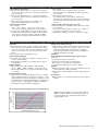
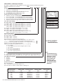
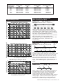
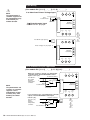
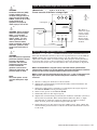
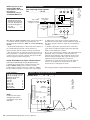
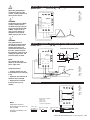
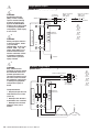
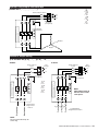
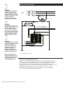
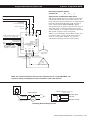
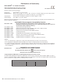
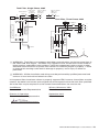
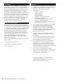
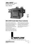
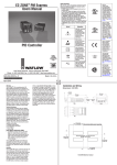
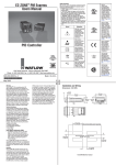
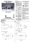
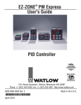
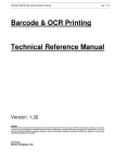
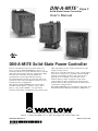
DIN-A-MITE ® Style C Solid-State Power Controller User’s Manual DIN-A-MITE Solid-State Power Controller Please consult this user’s manual when you place your new DIN-A-MITE into service. It contains all the necessary information to mount and wire the product into the application. This manual also contains all user-pertinent specifications and semiconductor fusing recommendations. Refer to national and local electrical code safety guidelines whenever you install electrical equipment. The Watlow DIN-A-MITE power controller includes single-phase, 3-phase, 2-leg, and 3phase, 3-leg, 120 to 600VÅ (ac) operation. Current switching capabilities range from 30 to 80A, depending on the model ordered. See the output rating curves. Zero-cross variable time base or V‡ (ac/dc) input contactor versions are available. Shorted SCR (silicon controlled rectifier) and open-heater protection is available on some zero-cross models. Phase angle and phase angle with current limit is also available on single-phase models. The model number indicates the power controller’s configuration. The DIN-A-MITE power controller is designed and manufactured by Watlow in Winona, Minnesota. 1241 Bundy Boulevard, Winona, Minnesota USA 55987 Phone: +1 (507) 454-5300, Fax: +1 (507) 452-4507 http://www.watlow.com 0600-0025-0009 Rev P January 2015 Made in the U.S.A. General Specifications Operator Interface • Command signal input and indication light • Alarm output and indication light • Current limit indication LED Amperage Rating See the output rating curve chart on page 5 for all the natural convection, fan-cooled, and throughwall mount models. Ratings are into a resistive heater load • Maximum surge current for 16.6 milliseconds, 1,350 A peak • Maximum I2t for fusing is 9100 A2s • Latching current: 500mA minimum • Holding current: 200mA minimum • Fan current: 0.14 A for 24VÎ (dc); 0.12 A for 120VÅ (ac); 0.06A for 240VÅ (ac) • Off-state leakage 1mA at 25°C (77°F) maximum • Power dissipation is 1.2 watts per amp switched per controlled leg. • 200KA SCCR type 1 and 2 approved with the recommended fusing (see page 4) Line Voltage • 24 to 48VÅ (ac) units: 20VÅ minimum to 53VÅ maximum • 120 to 240VÅ (ac) units: 48VÅ minimum to 265VÅ maximum • 277 to 600VÅ (ac) units: 85VÅ minimum to 660VÅ maximum Alarms (zero cross models only) Shorted SCR Alarm Option • Alarm state when the input command signal is off and a 10 A or more load current is detected by the current transformer (two turns required for 5 A or three turns for 2.5 A). Open Heater Alarm Option • Alarm state when the input command signal is on and the load current detected by the current transformer is less than the alarm set point. Available with Input Control Signal option S only. Alarm Output • Energizes on alarm, non-latching • Triac 24 to 240VÅ (ac), external supply with a current rating of 300 mA @ 25°C (77°F), 200mA @ 50°C (122°F), 100mA @ 80°C (176°F) and a holding current of 200 µA with a latching current of 5mA typical. Agency Approvals • ROHS • CE with proper filter: 2004/108/EC Electromagnetic Compatibility Directive EN 61326: Industrial Immunity Class A emissions Not suitable for Class B environments. 2006/95/EC Low Voltage Directive EN 50178 Safety Requirements Installation category III, Pollution degree 2 Phase angle and phase angle with current limit Input Control Signal Types (P and L) are not CE approved. • UL® 50 Type 4X Enclosure and UL ANSI/ISA 12.12.01 Temperature Code T4A The through-wall heatsink package is suitable for use in Class I, Division 2 Groups A, B, C and D Hazardous Locations or unclassified or non-hazardous locations. 2 WATLOW DIN-A-MITE Style C User's Manual çWARNING – EXPLOSION HAZARD SUBSTITUTION OF ANY COMPONENTS MAY IMPAIR SUITABILITY FOR CLASS I, DIVISION 2. çWARNING – EXPLOSION HAZARD DO NOT DISCONNECT WHILE THE CIRCUIT IS LIVE OR UNLESS THE AREA IS KNOW TO BE FREE OF IGNITIBLE CONCENTRATIONS. • UL® 508 listed and C-UL®, File E73741 • Shock and vibration tested to IEC 60068-2-32 • Vibration tested to IEC 60068-2-6 Input Terminals • Compression: Will accept 0.2 to 1.5 mm2 (24 to 16 AWG) wire • Torque to 0.5 Nm (4.4 in-lb) with a 3.5 mm (1/8 in) blade screwdriver • Wire strip length 5.5 mm (0.22 in) • Line and load wire insulation rating must be 75C or higher, copper conductor only Line, Load and Ground Terminals • Compression: Will accept 2.5 to 25 mm2 (14 to 3 AWG) wire • Torque to 2.7 Nm (24 in-lb) with a 6.4 mm (1/4 in) blade screwdriver, or a Type 1A #2 Pozi driver. • Retorque after 48 hours to minimize wire cold flow. • Retorque line and load terminals every 3 to 6 months. • Wire strip length 11 mm (7/16 in) Operating Environment • See the output rating curve chart on page 5. • 0 to 90% RH (relative humidity), non-condensing • Storage temperature: -40 to +85°C (-40 to 185°F) • Insulation only tested to 3,000 meters DIN Rail Mount • DIN EN 50022, 35 by 7.5 mm • Minimum clipping distance: 34.8 mm (1.37 in) • Maximum clipping distance: 35.3 mm (1.39 in) Back Panel Mount • Four mounting holes M4 (No. 8) fastener Through-Wall Mount • See page 8 for through-wall cutout NOTE: Mount cooling fins vertically. Cooling fan power terminals: quick connect, 1/8" push on, 16-14 AWG wire. Amp part no. 640929-1 or equivalent Weight • 1.0 to 1.9 kg (2.2 to 4.2 lb) depending upon model Specifications are subject to change without notice. Note: The DIN-A-MITE C was changed in April of 2007 to add the shut down circuitry (fan failure) to all units shipped. The shut down temperature is approximately 117C. Additional Specifications for Contactors and Proportional Controls Control Mode, Zero-Cross • Input Control Signal Type C: VÎ (dc) input contactor. To increase service life, the cycle time should be less than 3 seconds. • Input Control Signal Type K: VÅ (ac) input contactor. To increase service life, the cycle time should be less than 3 seconds. • Input Control Signal Type F: 4 to 20mAÎ (dc) proportional variable time base control. Input Command Signal • AC contactor 24VÅ ±10%, 120VÅ +10%/-25%, 240VÅ (ac) +10%/-25% @ 25mA maximum per controlled leg • Do not use the DIN-A-MITE Vac-input models with a temperature controller that includes an RC snubber circuit across its output. Remove the RC snubber circuit before placing the DIN-A-MITE into service. • DC Contactor 4.5 to 32VÎ (dc): maximum current @ 4.5VÎ (dc) is 6mA per leg. Add 2mA per LED used to the total current. • Loop powered linear current 4 to 20mAÎ (dc): loop-powered. Input Type F0 option only. (Requires current source with 6.2VÎ (dc) available. No more than three inputs connected in series.) Linearity (Input Control Signal Type F) • Full on point 19.5 to 19.9mAÎ (dc), maximum voltage of 6.2V peak. • ±5% input to output power accuracy, 0% to 100% of span (4.3 to 19.7mA or 12.3 to 19.7mA). • Temperature stability is less than 0.15%/°C change. Additional Specifications: Phase Angle; Phase Angle Current Limit; & Single Cycle VTB Operation • Burst firing (zero-cross) control, single-cycle variable time base, Type S single-phase and 3-phase. Unit is not on for more than one full cycle under 50% power and not off for more than one full cycle above 50% power. • Phase angle control, single-phase only Input Command Signal • 0 to 20mA, 4 to 20mA, 12 to 20mA, Î (dc), 0 to 5VÎ, 1 to 5VÎ, and 0 to 10VÎ • Input impedance 250Ω for 4 to 20mA, 5kΩ for linear voltage input Output Voltage • 100 to 120VÅ (ac), 200 to 208VÅ, 230 to 240VÅ, 277VÅ, 400VÅ, 480VÅ, 600VÅ, -15%/+10%, 50 or 60 Hz independent +/-5% (Input Control Signal Type L, P and S) Phase Angle Accuracy • Output on time is directly proportional to the command signal. Output on time is accurate to within 5% of the command signal input at 25 degrees C ambient. See chart below for command signal input to output power transfer function. Temperature stability at ambient temperature is less than 0.25%/degrees C. Single Cycle VTB Accuracy • Output power is directly proportional to the command signal. Output power is accurate to within 5% of the command signal input at 25 degrees C ambient. Temperature stability is less than 0.25%/degrees C ambient temperature change. Soft Start (Phase Angle Input Control Signal Type P and L) Typically: • 5 seconds soft start on power up • Soft start on thermostat overtemperature • Soft start on 1/2 cycle drop out detection • 1 second soft switching on set point change Options • Manual Control Kit (1kΩ, 1 turn potentiometer with dial scale labeled 0 to 100%) 08-5362 • Alarm option is not available on phase angle type P or type L. Resolution • Better than 0.1% of input span with respect to output change. Phase Angle Command Signal Input to Output Power 100.0 Note: The DIN-A-MITE C was changed in April of 2007 to add the shut down circuitry (fan failure) to all units shipped. The shut down temperature is approximately 117C. 90.0 Output (%P) 80.0 70.0 60.0 50.0 40.0 30.0 20.0 10.0 0.0 0 10 20 30 40 50 60 70 80 90 100 Command Signal Input (%P) WATLOW DIN-A-MITE Style C User's Manual 3 DIN-A-MITE C Ordering Information To order, complete the code number on the right with the information below: Style C solid-state power controller D __ C __ __ - __ __ __ __ - __ __ __ __ __ Phase 1 = single-phase, 1 controlled leg 2 = 3-phase, 2 controlled legs 3 = 3-phase, 3 controlled legs (use with four-wire wye) 8 = 2 independent zones (input control C, K) 9 = 3 independent zones (input control C, K) Current Rating Table Model Current (first 4 digits at 50°C of part number) (122°F) Cooling and Current Rating Per Leg 0 = Natural convection standard DIN rail or panel heatsink 1 = Fan-cooled 120VÅ (ac) standard DIN rail or panel heatsink 2 = Fan-cooled 240VÅ (ac) standard DIN rail or panel heatsink 3 = Fan-cooled 24VÎ (dc) fan standard DIN rail or panel heatsink T = Natural convection through-wall or cabinet heatsink (UL 50) DC10 DC1T DC11, DC12, DC13 DC20, DC80 DC2T, DC8T DC21, DC22, DC23 DC81, DC82, DC83 DC30, DC90 DC3T, DC9T DC31, DC32, DC33 DC91, DC92, DC93 Line and Load Voltage 02 = 24 to 48VÅ (ac) (Input Control Signal C, F, or K only) 12 = 100 to 120VÅ (ac) (Input Control Signal L, P or S only) 20 = 200 to 208VÅ (ac) (Input Control Signal L, P or S only) 24 = 120 to 240VÅ (ac) (Input Control Signal C, F or K only); 230 to 240VÅ (ac) (Input Control Signal L, P or S only) 27 = 277VÅ (ac) (Input Control Signal L, P or S only) 40 = 400VÅ (ac) (Input Control Signal L, P or S only) 48 = 480VÅ (ac) (Input Control Signal L, P or S only) 60 = 277 to 600VÅ (ac) (Input Control Signal C, F or K only); 600VÅ (ac) (Input Control Signal L, P or S only) Input Control Signal C0 = 4.5 to 32VÎ (dc) contactor K1 = 22 to 26VÅ contactor K2 = 100 to 120VÅ contactor K3 = 200 to 240VÅ contactor F0 = Proportional 4 to 20 mA (loop powered) L(0 to 5) = Phase angle with current limiting (DC1 only, Alarm 0 only, includes one current transformer - Single phase only) P(0 to 5) = Phase angle (DC1 only, Alarm 0 only - Single phase only) S(0 to 5) = Single-cycle variable time base (Select one of the following input options for L, P, S, (0 to 5)) 0 = 4 to 20mA 1 = 12 to 20mA (for Input Control Signal option S only) 2 = 0 to 20mA 3 = 0 to 5VÎ (dc) proportional 4 = 1 to 5VÎ (dc) proportional 5 = 0 to 10VÎ (dc) proportional User Manual Language 0 = English 1 = German 2 = Spanish 3 = French Custom Part Numbers 00 = Standard part 1X = 1-second soft start (control option P, L) XX = Any letter or number, custom options, labeling, etc. Note: • Recommended fusing options to meet 200KA SCCR, type 1 and 2 approved. All other fuse and SCR combinations are defaulted to 5KA SCCR per UL508A and NEC guidelines. Semiconductor Fuses for Applications Through 600VÅ (ac): 30A 40A 50A 63A 80A 100A 4 Watlow Fuse P/N 17-8030 17-8040 17-8050 17-8063 17-8080 17-8100 WATLOW DIN-A-MITE Style C User's Manual Bussman Fuse P/N FWP30A14F FWP40A14F FWP50A14F FWP63A22F FWP80A22F FWP100A22F 30 A 35 A 55 A Not CE compliant for conducted or radiated emissions Alarm 0 = No alarm S = Shorted-SCR alarm (not available on Phase options 8 & 9 or Control options L & P) H = Open-heater and shorted-SCR alarm (for Input Control Signal option S only) Semiconductor Fuse Rating 55 A 62 A 75 A 40 A 46 A 65 A Watlow Holder P/N 17-5114 17-5114 17-5114 17-5122 17-5122 17-5122 Ferraz Holder P/N USM141i USM141i USM141i US221i US221i US221i Combination Fuses for Applications Through 600VÅ (ac): Semiconductor Fuse Rating Watlow Fuse P/N Bussman P/N Watlow Holder P/N 30A 40A 50A 63A 80A 100A 0808-0325-0030 0808-0325-0040 0808-0325-0050 0808-0325-0060 0808-0325-0080 0808-0325-0100 DFJ30 DFJ40 DFJ50 DFJ60 DFJ80 DFJ100 0808-0326-1530 0808-0325-3560 0808-0325-3560 0808-0325-3560 0808-0325-7010 0808-0325-7010 Bussmann Holder P/N CH30J1i CH60J1i CH60J1i CH60J1i J60100-1CR J60100-1CR Extended Heater And SCR Life With Variable Time Base Output Rating Curves 90 85 20% Power, 3 AC line cycles on, 12 cycles off Natural Convection 80 50% Power, 3 AC line cycles on, 3 cycles off 75 70 65 50 45 40 leg leg , 2- , 3- se ha 3- p 55 e as ph leng Si 60 e has 3- p Maximum Internal Enclosure Ambient Temperature (°C) Models: DC _ _ - [02, 24, 60] F0 - _ _ _ _ DIN-A-MITE Style C Ratings at 100% On 35 30 25 0 5 10 15 20 25 30 35 40 45 50 55 60 65 70 75 80 Current (Amps) into a Resistive Load With variable time base control, the power controller automatically adjusts the time base and output power with respect to process input. Accelerated life testing verified that the variable time base control significantly reduces expansion and contraction of the heater element. This extends heater and SCR life while improving the process temperature control. You save money on heaters, down time and maintenance. DIN-A-MITE Style C Ratings at 100% On 80 75 Ó6 70 65 Fan-Cooled e, 45 3- le 40 e as ph leg le 2e, as as ph 50 ph 3- 55 g Sin 60 g 35 30 25 0 5 10 15 20 25 30 35 40 45 50 55 60 65 70 75 80 85 90 Current (Amps) into a Resistive Load DIN-A-MITE Style C Ratings at 100% On 80 Recommended maximum enclosure temperature is 80 C (176 F) 75 50% Power, 1 AC line cycle on, 1 cycle off With single-cycle variable time base (VTBS) control, at 50% power, power is on one cycle, and off one cycle. At 25%, it is on for one cycle and off for three. Under 50%, the unit is not on for more than one consecutive cycle. Over 50%, the unit is not off for more than one consecutive cycle. This model will work with a linear voltage input, a 4 to 20mA input or a potentiometer input. Phase Angle 70 65 60 3ph 2- g le g -le ,3 40 e, se 45 as ha 50 35 30 25 0 Models: DC1 _ - _ _ [L, P] _ - 0 _ _ _ e as ph l e- 55 ng Si Through-Wall Heatsink 3- p Ambient Air Around Heatsink Fins ( C) Models: DC _ _ - _ _ S _ - _ _ _ _ 25% Power, 1 AC line cycle on, 3 cycles off 3- Maximum Internal Enclosure Ambient Temperature (°C) Single-Cycle Variable Time Base 5 10 15 20 25 30 35 40 45 50 55 60 65 70 75 80 Current (Amps) into a Resistive Load Phase angle control (control Type P) is infinitely variable inside the sine wave. This provides a variable voltage and/or current output. This option includes soft start and line voltage compensation. This model will work with a linear voltage input, a linear current source input or a potentiometer input. This is single-phase only. Alarms not available on phase angle models. WATLOW DIN-A-MITE Style C User's Manual 5 Mount Dismount 4 1 3 2 1 1. Push the unit in and down to catch the rail hook on top of the rail. 1. Press down on the release tab while rotating the unit up and away from the rail. 2. Rotate the bottom of the unit in toward the rail. 3. The rail clasp will audibly “snap” into place. If the DIN-A-MITE does not snap into place, check to see if the rail is bent. 4. Mount the cooling fins vertically. ç3 WARNING: Only authorized and qualified personnel should be allowed to install and perform preventive and corrective maintenance on this unit. Failure to follow this guideline could result in damage to equipment, and personal injury or death. Unit Dimensions - Fan-Cooled Side 102 mm (4.0 in) clearance for air flow and wire bending radius 146 mm (5.74 in) 102 mm (4.0 in) 142 mm (5.59 in) 44 mm (1.73 in) 131 mm (5.17 in) 57 mm (2.26 in) 150 mm (5.89 in) 79 mm (3.10 in) 127 mm 194.1 mm (5.00 in) (7.64 in) 5 WARNING: Hot surface, do not touch the heat sink. Failure to follow this guideline could result in personal injury. Rail Release Tab (pull down) Front panel is touch-safe, no clearance is required. 102 mm (4.0 in) minimum 102 mm (4.0 in) clearance for air flow and wire bending radius ç Mount the cooling fins vertically. ç Ó3 5 6 WATLOW DIN-A-MITE Style C User's Manual ç Ó3 Unit Dimensions - Rail-Mounted Top ç Ó3 WARNING: Only authorized and qualified personnel should be allowed to install and perform preventive and corrective maintenance on this unit. Failure to follow this guideline could result in damage to equipment, and personal injury or death. 5 WARNING: Hot surface, do not touch the heat sink. Failure to follow this guideline could result in personal injury. 146 mm (5.74 in) Side by side clearance for wire routing 5 Ground wire entry 13 mm (0.50 in) 83 mm (3.25 in) Side 102 mm (4.0 in) clearance for air flow and wire bending radius 146 mm (5.74 in) 102 mm (4.0 in) 142 mm (5.59 in) 44 mm (1.73 in) 131 mm (5.17 in) 57 mm (2.26 in) 150 mm (5.89 in) 79 mm (3.10 in) ç Mount the cooling fins vertically. Rail Release Tab (pull down) 127 mm (5.00 in) 102 mm (4.0 in) minimum 102 mm (4.0 in) clearance for air flow and wire bending radius Front panel is touch-safe, no clearance is required. Front 38 mm (1.51 in) 46 mm (1.81 in) 54 mm (2.11 in) Allowance for M4 (#8 Fastener) 1 2 3 138 mm (5.45 in) DIN-EN 50022 35 by 7.5 mm rail (clipping distance = 34.7 to 35.3 mm [1.366 to 1.390 in]) 87 mm (3.42 in) 4 5 6 48 mm (1.89 in) Allowance for M4 (#8 Fastener) Unit Dimensions - Through-Wall (Cabinet Panel) Top 57 mm (2.25 in) outside (any gauge) 114 mm (4.50 in) ç Ó3 5 55 mm (2.17 in) inside (12 gauge) Sheet Metal (12 gauge) Front panel is touch-safe, no clearance is required. WATLOW DIN-A-MITE Style C User's Manual 7 Mounting Mounting procedure for UL® 50 Type 4X Enclosure and UL® / ANSI 12.12.01 Throughwall mount models Materials included: (1) Silicone gasket Front M5 (0.8 by 10 mm) (8) M5 Internal Tooth Lock Washer (8) included 122 mm (4.81 in) 102 mm (4.0 in) minimum clearance for air flow (top and bottom) Ground lug (2-8 GA 1 Panel Opening Outline 2 3 (8) M5 screws and lockwashers 178 mm (7.00 in) (1) DIN-A-MITE C through-wall 4 1. Drill and cut the panel as shown in the dimensioned drawing at right. 2. Remove the mounting screws from the heatsink. 3. Peel off the protective film from the silicone gasket. Stick the gasket to the heatsink so the gasket holes line up with the screw holes in the heatsink. 5 6 10 mm (0.4 in) minimum clearance for air flow (both sides) Drill 5.8 mm (0.228 in) (8) Typical Panel Opening Heatsink Outline 9.5 mm (0.375 in) Reference 10.8 mm (0.425 in) 41.3 mm (1.625 in) 117.5 mm (4.625 in) 4. Mount the heatsink vertically. Torque to 2.26 to 2.82 Nm (20 to 25 in-lb). 161.9 mm (6.375 in) 148.6 mm (5.850 in) 8.6 mm (0.338 in) Reference 7.0 mm (0.275 in) 26.3 mm (1.034 in) 78.8 mm (3.103 in) 98.1 mm (3.862 in) 105.1 mm (4.137 in) Current Transformer Dimensions 8 WATLOW DIN-A-MITE Style C User's Manual ç Ó1 Input Wiring (For models DC [1, 2, 3] _ - _ _ [C, F, K] _ - _ _ _ _) 1 WARNING: Use National Electric (NEC) or other country-specific standard wiring practices to install and operate the DINA-MITE. Failure to do so may result in damage to equipment and property, and/or injury or loss of life. 3 Ó WARNING: Only authorized and qualified personnel should be allowed to install and perform preventive and corrective maintenance on this unit. Failure to follow this guideline could result in damage to equipment, and personal injury or death. 4 Ó WARNING: Do not use the DIN-A-MITE Vac-input models with a temperature controller that includes an RC snubber circuit across its output. Remove the RC snubber circuit before placing the DIN-A-MITE into service. 7 + 8 9 10 11 12 13 14 15 16 17 18 19 20 VÅ (ac) Input: 4 to 20mAÎ (dc) Input: 4.5 to 32VÎ (dc) Input: + + - 7 8 9 + - 7 8 9 + - 2 ç Ó1 Ó3 Ó4 3 Gain Adjustment Potentiometers Bias Open Heater Note: Use tool Bourns H91 to adjust Limit Signal Alarm Zone 1 Zone 2 Zone 3 4 5 6 Typical DIN-A-MITE Current Draw: DC21-24C0-5000 4.5Vdc 9.0Vdc 13.18mA 15.02mA 12.0Vdc 16.09mA 24.0Vdc 20.14mA 32.0Vdc 22.53mA Multizone Input Wiring (For models DC [8, 9] _ - _ _ _[C, K] - 0 _ _ _) 2-zone 1 Zone 1 VÎ (dc) Input: + - Zone 1 7 + V~ (ac)Zone Input: 3 VÎ (dc)8Input: - + 9 10 11 12 13 Zone 3 V~ (ac) Input: NOTE: Alarm options not available with multizone input option. 7 + 8 9 10 11 + 12 13 14 15 16 17 18 19 20 2 3 Gain Bias Adjustment Potentiometers Open Heater Limit Signal Alarm Zone 2 Zone 3 4 5 6 1 2 3 Zone 1 ç Ó1 Ó3 Ó4 3-zone Zone 1 VÎ (dc) Input: Zone 2 VÎ (dc) Input: + Zone 1 V~ (ac) Input: 7 - Zone 3 VÎ (dc) 8Input: Zone 2 V~ (ac) Input: Zone 3 V~ (ac) Input: 9 10 11 12 13 + + + - 7 + 8 9 + 10 11 + 12 13 14 15 16 17 18 19 20 Gain Bias Adjustment Potentiometers Open Heater Limit Signal Alarm Zone 1 Zone 2 Zone 3 4 5 6 WATLOW DIN-A-MITE Style C User's Manual 9 Input Wiring ç NOTE: The potentiometer is customer-supplied. For the potentiometer only, order Watlow part number 08-5362. (For models DC [1, 2, 3] _ - _ _ [L, P, S] _ - _ _ _ _) 4 to 20mA and Linear Voltage Input 1 2 3 Counterclockwise 1kΩ Potentiometer Clockwise 1kW Potentiometer Input Use with 0 to 5VÎ (dc) Input 4 to 20mAÎ (dc) Input + - Linear voltage VÎ (dc) Input 7 8 9 7 + 8 9 CW 10 11 12 13 14 15 16 17 18 19 20 + - + - Gain Bias Adjustment Potentiometers Open Heater Limit Signal Zone 1 Zone 2 Zone 3 4 5 6 1 7 + 8 9 10 11 12 13 14 15 16 17 18 19 20 Alarm 2 ç Ó1 Ó3 3 Gain Bias Adjustment Potentiometers Open Heater Limit Signal Alarm Zone 1 Zone 2 Zone 3 4 5 6 Auto and Manual Input Application (For models DC [1, 2, 3] _ - _ _ [L, P, S] [3, 4] - _ _ _ _ ) When you use the 4 to 20 mAÎ (dc) temperature controller output and the DIN-A-MITE control input 1 to 5VÎ (dc). Counterclockwise 4 to 20mA Î 250Ω 200Ω resistor (dc) signal from the Auto + temperature controller 1kΩ Manual Potentiometer 1 2 3 - NOTE: The potentiometer and resistors are customersupplied. For the potentiometer control assembly only, order Watlow part number 08-5362. Clockwise If you use the 0 to 5VÎ (dc) temperature controller output, order the DIN-A-MITE control input 0 to 5VÎ (dc). Counterclockwise 0 to 5VÎ (dc) signal Auto from the temperature 1kΩ controller Manual Potentiometer Clockwise 10 WATLOW DIN-A-MITE Style C User's Manual 7 + 8 9 CW 10 11 12 13 14 15 16 17 18 19 20 7 + 8 9 CW Gain Bias Adjustment Potentiometers Open Heater Limit Signal Alarm Zone 1 Zone 2 Zone 3 4 5 6 ç Ó1 Ó3 Ó1 WARNING: Use National Electric (NEC) or other country-specific standard wiring practices to install and operate the DINA-MITE. Failure to do so may result in damage to equipment and property, and/or injury or loss of life. Input Wiring Phase Angle with Current Limit (Model DC1 _ - _ _ L [0, 1, 2, 3, 4, 5] - _ _ _ _ ) Linear current and linear voltage input 1 Input Signal: Ó2 WARNING: Wiring examples show L2 in phase-to-phase, 200VÅ (ac) and above configuration. In phase-toneutral, 100VÅ (ac) and above applications, L2 is neutral and must not be fused or switched. Failure to follow this guideline could result in personal injury or death. Ó3 WARNING: Only authorized and qualified personnel should be allowed to install and perform preventive and corrective maintenance on this unit. Failure to follow this guideline could result in damage to equipment, and personal injury or death. NOTE: The alarm options are not available with phase angle units. Current Transformer (CT) + - 7 8 9 10 11 12 13 14 15 16 17 18 19 20 2 ç Ó1 3 + Gain Bias Adjustment Potentiometers Open Heater CT1 CT1 Limit Signal Zone 1 4 Alarm Zone 2 5 Zone 3 6 The Zone 3 indicator light serves as the current-limit indicator in phase-angle, current-limit models. Load Wire Heater Current Limit Adjustment Procedure The DC1 _ - _ _ L _ - 0 _ _ _ model is a phase angle-controller that can limit the maximum current to the load. A potentiometer on the DIN-AMITE adjusts the current limit setting. Use the following steps to adjust the current limit on initial setup. The purpose of the procedure is to bring the power to the load slowly so that the desired maximum current to the load is not exceeded before the current limit is adjusted. NOTE: The DIN-A-MITE is shipped factory-calibrated with the potentiometer adjusted fully clockwise (no current limiting). Adjust the potentiometer clockwise to increase the current; counterclockwise to decrease the current. NOTE: A short overcurrent through the load may occur, as the circuitry detects the high current, if the input signal from the temperature controller is abruptly increased. 1. Attach a clamp-on ammeter to the load line. 2. Adjust the current limit potentiometer fully counterclockwise (for minimum current flow). 3. Turn the temperature controller on and adjust the input signal to the DIN-A-MITE for zero percent power. 4. Turn on the power to the DIN-A-MITE. 5. Gradually increase the input signal. 6. Adjust the current limit potentiometer clockwise until the current to the load is measurable. The current limit indicator (Zone 3) light should turn on until the output is allowed to go full on, with no limit. At that point, the indicator light will turn off. 7. Gradually increase the input signal to 100% power, then adjust the current limit potentiometer to obtain the desired maximum current to the load. WATLOW DIN-A-MITE Style C User's Manual 11 NOTE:If you plan to wire multiple DIN-A-MITE alarm outputs, you need to include an intermediate relay for each DIN-A-MITE used. Non-latching Alarm Option DC _ _ - _ _ _ _ - [H, S] _ _ _ V~ 120 or 240V~ @ 300mA maximum energizes on alarm Load Current Single phase load wire passes through one CT. Number of passes through CT: 5 to 9A 10 to 65A Single-phase Alarm 1 7 8 9 10 11 12 13 14 15 16 17 18 19 20 Alarm Relay or Indicator 1A 2 1 Current Transformer (CT) + + + - 2 ç Ó1 Ó3 3 Triac Gain Bias Adjustment Potentiometers ALM Open Heater ALM CT1 CT1 ALM = Alarm CT = Current Transformer Limit CT2 CT2 Signal Alarm CT3 CT3 Zone 1 4 Zone 2 Zone 3 5 6 Load Wire Heater 2. Adjust the open heater alarm adjustment potentiometer until the alarm indicator light on the front panel is full on, with no intermittent cycling. 3. Slowly adjust the potentiometer until the open heater indicator light just turns full off, with no intermittent cycling. If you are getting false alarms, the adjustment is probably set too sensitive and should be readjusted towards the off condition of the openheater indicator light. The open heater pot is adjusted counter clockwise to increase sensitivity to open heater detect (red light on sooner) or clockwise to desensitize to open heater detect (red light on later). The Watlow DIN-A-MITE alarm option provides a common alarm output for open-heater or shorted SCR conditions. This is a non-latching alarm. • A shorted SCR alarm is detected when there is no command signal and a load current is detected. The alarm output is then energized. • An open-heater or partial open-heater state is detected when a command signal is present and a reduced or no output current is detected. The alarm output is then energized. Setup Procedure for Open-Heater Alarm (For Input Control Signal type S option only) 1. With the temperature control wired to the DIN-A-MITE SCR power control, set the temperature control output to “full on” (20mA for 4 to 20mA output, or 5V for 0 to 5V output). Load Current 3-phase 2-leg load wire passes through 2 CTs. Number of passes through each: 5 to 6A 7 to 9A 10 to 14A 15 to 19A 20 to 33A 34A and up NOTE: Load wires must pass through each current transformer in the same direction. 7 6 4 3 2 1 No setup procedure required for shorted SCR alarm. 3-phase, 2-leg Open Heater Alarm (Model DC2 _ - _ _ S _ - H _ _ _ ) 1 7 8 9 10 11 12 13 14 15 16 17 18 19 20 + + + - 2 Adjustment Potentiometers Gain Bias ALM ALM CT1 ç Ó1 Ó3 3 ALM = Alarm CT = Current Transformer CT1 Open Heater Limit CT2 CT2 Signal Alarm CT3 CT3 Zone 1 Zone 2 Zone 3 4 5 6 T3 white T2 black Current Transformers 12 WATLOW DIN-A-MITE Style C User's Manual Heater T1 ç NOTE: Adjust the potentiometer clockwise to increase the current; counterclockwise to decrease the current. 3-phase, 2-leg Shorted SCR Alarm (Model DC2 _ - _ _ [C, F, K, S] _ - S _ _ _ ) 1 7 8 9 10 11 12 13 14 15 16 17 18 19 20 1 Ó WARNING: Use National Electric (NEC) or other country-specific standard wiring practices to install and operate the DINA-MITE. Failure to do so may result in damage to equipment and property, and/or injury or loss of life. + + + - 2 Adjustment Potentiometers Gain Bias ALM ALM CT1 ç Ó1 Ó3 3 ALM = Alarm CT = Current Transformer CT1 Open Heater Limit CT2 CT2 CT3 CT3 Alarm Signal Zone 1 Zone 2 Zone 3 4 5 6 T3 T2 3 Heater T1 Ó WARNING: Only authorized and qualified personnel should be allowed to install and perform preventive and corrective maintenance on this unit. Failure to follow this guideline could result in damage to equipment, and personal injury or death. NOTE: The shorted SCR alarm option is not available with phase angle units. 3-phase, 3-leg Alarm, Shorted SCR and Open Heater Alarm (Model DC3 _ - _ _ _ _ - [S, H] _ _ _ ) Shorted SCR Alarm Only 1 2 3 T3 CT 7 8 9 10 11 12 13 14 15 16 17 18 19 20 CT1 Gain Bias T2 T1 Open Heater ALM = Alarm CT = Current Transformer 15 CT1 Limit CT2 CT2 Signal 16 Alarm CT3 CT3 Zone 1 Zone 2 Zone 3 4 5 6 T3 Torque Guidelines Neutral • Properly torque line and load terminals to 2.7 Nm (24 in-lb). white black • Retorque after 48 hours to minimize wire cold flow. • Retorque line and load terminals every 3 to 6 months. white black Heater T1 T2 Fan-Cooled 7 8 9 10 11 12 13 14 15 16 17 18 19 20 Fan power required 24VÎ (dc) 115V~ (ac) 240V~ (ac) (customer supplied) NOTE: Cooling fan terminals: Amp part no. 640929-1 or equivalent ç Ó1 Ó3 white Current Transformers (CT) 1 Quick connect 1/8" push on, #16-14 AWG Neutral Current Transformer (CT) Adjustment Potentiometers ALM ALM 6 5 4 + + + - 24VÎ (dc) Red wire (+) Black wire (-) Phase to neutral L1 L2 2 3 + Gain Adjustment Potentiometers Bias ç Ó1 Ó3 Open Heater CT1 CT1 Limit Signal Alarm Zone 1 Zone 2 Zone 3 4 5 6 Phase to phase L1 L2 WATLOW DIN-A-MITE Style C User's Manual 13 ç 1 Single-phase Output (Model DC1 _ - _ _ _ _ - _ _ _ _ ) Ó 2 Ó WARNING: Wiring examples show L2 in phase-to-phase, 200VÅ (ac) and above configuration. In phase-toneutral, 100VÅ (ac) and above applications, L2 is neutral and must not be fused or switched. Failure to follow this guideline could result in personal injury or death. Limit Control Contacts (if required) Semiconductor Fuse 1 7 8 9 10 11 12 13 14 15 16 17 18 19 20 2 Phase-to-neutral 100V~ (ac) and above Phase-to-phase 200V~ (ac) and above L1 L1 L2 Neutral 3 + + + - Gain Internal Busbar WARNING: Use National Electric (NEC) or other countryspecific standard wiring practices to install and operate the DIN-A-MITE. Failure to do so may result in damage to equipment and property, and/or injury or loss of life. ALM ALM ç Ó1 Ó2 Ó3 Adjustment Potentiometers Bias Open Heater CT1 CT1 Limit CT2 CT2 Signal Alarm CT3 CT3 Zone 1 Zone 2 Zone 3 4 5 6 Heater 3 WARNING: Only authorized and qualified personnel should be allowed to install and perform preventive and corrective maintenance on this unit. Failure to follow this guideline could result in damage to equipment, and personal injury or death. Torque Guidelines • Properly torque line and load terminals to 2.7 Nm (24 in-lb). • Retorque after 48 hours to minimize wire cold flow. • Retorque line and load terminals every 3 to 6 months. 3-phase, 2-leg Output (Model DC2 _ - _ _ _ _ - _ _ _ _ ) L1 L2 L3 1 7 8 9 10 11 12 13 14 15 16 17 18 19 20 + + + - 2 Gain ALM ALM CT1 Adjustment Potentiometers Bias Open Heater CT1 Limit CT2 CT2 Limit Control Contacts (if required) 3 Signal Alarm CT3 CT3 Zone 1 Zone 2 Zone 3 4 5 6 T3 T2 14 ç Ó1 Ó2 Ó3 Semiconductor Fuses Internal Busbar Ó WATLOW DIN-A-MITE Style C User's Manual Heater T1 3-phase, 3-leg Output, Four Wire Wye ç Ó1 Ó2 Ó3 (Model DC3 _ - _ _ _ _ - _ _ _ _ ) Semiconductor Fuses L1 L2 L3 1 2 3 + + + - 7 8 9 10 11 12 13 14 15 16 17 18 19 20 Limit Control Contacts (if required) Gain Adjustment Potentiometers Bias ALM Open Heater ALM CT1 CT1 Limit CT2 CT2 Signal Alarm CT3 CT3 Zone 1 Zone 2 Zone 3 4 5 6 Neutral Heater Multizone Output Wiring (For models DC [8, 9] _ - _ _ [C, K] _ - 0 _ _ _ 2-zone 3-zone Line Voltage L1 Semiconductor Fuses Semiconductor Fuses Line Voltage L1 L1 L1 1 7 8 9 10 11 12 13 14 15 16 17 18 19 20 2 3 + + + - Gain Bias ALM Open Heater ALM CT1 CT1 Limit CT2 CT2 Alarm Signal CT3 CT3 Zone 1 Zone 2 Zone 3 4 5 6 L1 Limit Control Contacts (if required) 2 Independent, Single-Phase Heaters Ó1 Ó2 Ó3 1 7 8 9 10 11 12 13 14 15 16 17 18 19 20 2 + + + - Gain Bias ALM Open Heater ALM CT1 CT1 Limit CT2 CT2 Signal Alarm CT3 CT3 Zone 1 Zone 2 Zone 3 4 5 6 Heater 1 Heater Heater 2 3 L2 L2 Limit Control Contacts (if required) 3 L2 NOTE: Independent loads do not have to be on the same phase. 3 Independent, Single-Phase Heaters L2 L2 NOTE: Do not exceed 80 amps on center leg. WATLOW DIN-A-MITE Style C User's Manual 15 ç System Wiring Example 1 Ó WARNING: Use National Electric (NEC) or other country-specific standard wiring practices to install and operate the DINA-MITE. Failure to do so may result in damage to equipment and property, and/or injury or loss of life. L3 480VÅ (ac) L2 L1 Breaker 480V~ (ac) 2 Ó 120V~ (ac) Quencharc WARNING: Wiring examples show L2 in phase-to-phase, 200 VÅ (ac) and above configuration. In phase-to-neutral, 100 VÅ (ac) and above applications, L2 is neutral and must not be fused or switched. Failure to follow this guideline could result in personal injury or death. CR1 Coil To DIN-A-MITE C Pin 7+, 8- (page 17) - F1 98 G1 99 + H1 Ó WARNING: Only authorized and qualified personnel should be allowed to install and perform preventive and corrective maintenance on this unit. Failure to follow this guideline could result in damage to equipment, and personal injury or death. Controller TC CC L4 CA K4 CB T1 T2 B5 S1 S2 D6 R1 R2 D5 3 High Limit TC PM6C2FA - ALAJAAA AC Common AC High CR1 = High-Limit Contactor NOTE: If you plan to wire multiple DIN-A-MITE alarm outputs, you need to include an intermediate relay for each DIN-A-MITE used. 16 Alternative Latching Alarm Circuit If there is a need for a latching alarm in the case of an open heater or shorted SCR, the DIN-A-MITE alarm circuit could be used as shown in the latching alarm example at right. If the DIN-A-MITE triac alarm output energizes, it will energize the RY1 (external alarm relay) mechanical relay coil. Once the RY1 coil is energized it will latch on (via the RY1A normally open contact) until the power to the relay is removed. You could cycle the power via a reset switch. The RY1B contact set can be used for alarm signaling. WATLOW DIN-A-MITE Style C User's Manual Ungrounded Delta or Wye Load 3-phase, 2-leg DIN-A-MITE Non-latching Alarm Option (models DC_ _ - _ _ S _ - H _ _ _ ) Open Heater and Shorted SCR Alarm The shorted SCR detector compares the input command signal and actual load current. If load current is present without an input signal then the shorted SCR alarm will energize a triac (on board the DIN-A-MITE) output. An open-heater or partial open-heater state is detected when a command signal is present and a reduced or no output current is detected. The alarm output is then energized. This is a non-latching alarm. This output can be used to drive various indication devices, such as a coil, light, buzzer, etc. See the alternative latching circuit section below. High-limit Contactor (CR1) Semiconductor Fuses 1 2 3 From Temperature Control Pin F1+, H1- (page 16) V~ (ac) Alarm Relay or Indicator 1A 120 or 240V~ (ac) @ 300mA maximum energizes on alarm 7 8 9 10 11 12 13 14 15 16 17 18 19 20 + + + - Gain Adjustment Potentiometers ALM ALM CT1 CT1 CT2 CT2 DIN-A-MITE DC20-48S0-H000 2-Leg Signal Bias Open Heater 6 Limit Alarm CT3 CT3 Zone 1 4 Zone 2 Zone 3 5 black 5 6 4 Ungrounded Wye Load white Current Transformers Delta Load NOTE: The current transformers must be in the controlled legs on a 2-leg DIN-A-MITE. The load wires must pass through the current transformers in the same direction. Triac 13 14 RY1B Reset Switch Normally open L1 RY1A (External alarm relay contacts, set A) RY1 Coil (External alarm relay contacts, set B) VÅ Common L2 Normally closed Latching Alarm Relay Circuit WATLOW DIN-A-MITE Style C User's Manual 17 Declaration of Conformity DIN-A-MITE® “C” Power Controller WATLOW Electric Manufacturing Company 1241 Bundy Blvd. Winona, MN 55987 USA ISO 9001since 1996. Declares that the following products: Designation: DIN-A-MITE® “C” Power Control Model Numbers: DC(1, 2, 3, 8 or 9)(0, 1, 2, 3 or T) – (02, 12, 20, 24, 27, 40, 48 or 60) (CX, K1, K2, K3, FX, SX) (0, H or S)(followed by any 3 numbers or letters) X = any number 0 - 9 Classification: Power Control, Installation Category III, Pollution degree 2, IP20 Rated Voltage: 24 to 600 V~ (ac), 50 or 60 Hz Meets the essential requirements of the following European Union Directives by using the relevant standards show below to indicate compliance. 2004/108/EC Electromagnetic Compatibility Directive EN 61326-1: 2013 Electrical equipment for measurement, control and laboratory use - EMC requirements (Industrial Immunity, Class A1,2,4 Emissions) Not for use in a Class B environment without additional filtering. EN 61000-4-2:2009 Electrostatic Discharge Immunity EN 61000-4-3:2010 Radiated Field Immunity 10V/m 80 MHz- 1GHz, 3V/m 1.4GHz-2.7GHz EN 61000-4-4:2012 Electrical Fast-Transient / Burst Immunity EN 61000-4-5:2006 Surge Immunity (Reviewed to IEC 61000-4-5 2014) EN 61000-4-6:2014 Conducted Immunity EN 61000-4-11:2004 Voltage Dips, Short Interruptions and Voltage Variations EN 61000-3-2:2009 Harmonic Current Emissions (Reviewed to IEC 61000-3-2 2014) EN 61000-3-3:2013 Voltage Fluctuations and Flicker3 EN 61000-3-11:2000 Voltage Fluctuations and Flicker ≤ 16A ≤ 75A with conditional connection NOTES 1 Use of an external filter is required to comply with conducted emissions limits. See note 4 below. 2 A Line Impedance Stabilization Network (LISN) was used for conducted emissions measurements. 3 To comply with flicker requirements, command signal models FX and SX will require a reduced source impedance. Cycle time on ON/OFF models CX, and K1, K2, K3 may need to be up to 175 seconds at 16A or have a reduced source impedance. 2006/95/EC Low-Voltage Directive EN 50178:1997 Electronic equipment for use in power installations. Per 2012/19/EU W.E.E.E Directive Please Recycle Properly. Compliant with 2011/65/EU RoHS2 Directive 4 Required External EMI Filters for DIN-A-MITE with More Than 6 Amp Loads An external ElectroMagnetic Interference (EMI) filter must be used in conjunction with the DIN-A- MITE for loads in excess of six amperes (6A) at 150 to 250 KHz. Watlow has verified that a tank filter will suppress EMI created by SCR power controllers to comply with the conducted emissions limits. DIN-A-MITE EMI Filters Description 18 Crydom Filter Watlow Filter Single-phase, 230VÅ (ac) 1F25 14-0019 Three-phase, 440VÅ (ac) 3F20 14-0020 WATLOW DIN-A-MITE Style C User's Manual Tank Filter, Single Phase, 230V Semiconductor Fuse Limit Control Contacts (if required) Phase-to-phase 200V~ (ac) and above 5A Filter 1 2 Phase-to-neutral 100V~ (ac) and above L1 L1 L2 Neutral Tank Filter, Three Phase, 440V 3 Filter 5A + + + - Gain ALM ALM L2 Adjustment Potentiometers 5A Bias L3 Open Heater CT1 1 CT1 2 3 Limit Control Contacts (if required) Limit CT2 CT2 L1 5A Internal Busbar Signal Alarm CT3 CT3 Zone 1 Zone 2 Zone 3 4 5 6 Heater 7 8 9 10 11 12 13 14 15 16 17 18 19 20 + + + - Gain Internal Busbar 7 8 9 10 11 12 13 14 15 16 17 18 19 20 Semiconductor Fuses ALM ALM CT1 Bias Open Heater CT1 Limit CT2 CT2 Signal Alarm CT3 CT3 Zone 1 Zone 2 Zone 3 4 5 6 T3 Heater T2 Alternate T1 ç WARNING: Tank filters may suppress desirable communications carried on power lines in the 150 to 250 KHz region. The filters may suppress carrier current such as that used for infant monitors and medical alert systems. Verify that suppressed carrier current or other desirable communications on power lines creates no hazard to people or property. Failure to observe this warning could result in damage to property, and or injury to death for personnel. ç WARNING: All filter installation and wiring must be performed by qualified personnel and conform to local and national electrical codes. In-line power filters have been shown to properly suppress EMI; however, these filters must be rated for the entire load current and are generally more expensive than the tank filter specified. An In-line filter may be required if carrier current communications are used on site. Joe Millanes Name of Authorized Representative Winona, Minnesota, USA Place of Issue Director of Operations Title of Authorized Representative September 2014 Date of Issue Signature of Authorized Representative WATLOW DIN-A-MITE Style C User's Manual 19 Warranty The Watlow DIN-A-MITE is warranted to be free of defects in material and workmanship for 36 months after delivery to the first purchaser for use, providing that the units have not been misapplied. Since Watlow has no control over their use, and sometimes misuse, we cannot guarantee against failure. Watlow's obligations hereunder, at Watlow's option, are limited to replacement, repair or refund of purchase price, and parts which upon examination prove to be defective within the warranty period specified. This warranty does not apply to damage resulting from transportation, alteration, misuse, abuse or improper fusing. Returns 1. • Ship to address • Bill to address • Contact name • Phone number • Method of return shipment • Your P.O. number • Detailed description of the problem • Any special instructions • Name and phone number of the person returning the product Technical Assistance If you encounter a problem with your Watlow controller, review your configuration information to verify that your selections are consistent with your application: inputs; outputs; alarms; limits; etc. If the problem persists after checking the configuration of the controller, you can get technical assistance from your local Watlow representative, by e-mailing your questions to [email protected] or by dialing +1 (507) 494-5656 between 7 a.m. and 5 p.m., Central Standard Time (CST). Ask for for an Applications Engineer. Call Watlow Customer Service, (507) 4545300, for a Return Material Authorization (RMA) number before returning any item for repair. We need the following information: 2. Prior approval and an RMA number, from the Customer Service Department, is required when returning any unused product for credit. Make sure the RMA number is on the outside of the carton, and on all paperwork returned. Ship on a Freight Prepaid basis. 3. After we receive your return, we will examine it and try to verify the reason for the return. 4. In cases of manufacturing defect, we will enter a repair order, replacement order or issue credit for material returned. 5. To return products that are not defective, goods must be in new condition, in the original boxes and they must be returned within 120 days of receipt. A 20 percent restocking charge is applied for all returned stock controls and accessories. 6. If the unit is unrepairable, it will be returned to you with a letter of explanation. 7. Watlow reserves the right to charge for no trouble found (NTF) returns. Please have the following information available when calling: • Complete model number • All wiring and load information • User’s Manual The DIN-A-MITE C User’s Manual is copyrighted by Watlow, Inc., © January 2015, with all rights reserved. 20 WATLOW DIN-A-MITE Style C User's Manual How to Reach Us Corporate Headquarters Europe Watlow Electric Manufacturing Company 12001 Lackland Road St. Louis, MO 63146 Sales: 1-800-WATLOW2 Manufacturing Support: 1-800-4WATLOW Email: [email protected] Website: www.watlow.com From outside the USA and Canada: Tel: +1 (314) 878-4600 Fax: +1 (314) 878-6814 Watlow France Tour d'Asnières. 4 Avenue Laurent Cély 92600 Asnières sur Seine France Tél: + 33 (0)1 41 32 79 70 Télécopie: + 33(0)1 47 33 36 57 Email: [email protected] Website: www.watlow.fr Latin America Watlow de México S.A. de C.V. Av. Fundición No. 5 Col. Parques Industriales Querétaro, Qro. CP-76130 Mexico Tel: +52 442 217-6235 Fax: +52 442 217-6403 Watlow GmbH Postfach 11 65, Lauchwasenstr. 1 D-76709 Kronau Germany Tel: +49 (0) 7253 9400-0 Fax: +49 (0) 7253 9400-900 Email: [email protected] Website: www.watlow.de Watlow Italy S.r.l. Viale Italia 52/54 20094 Corsico MI Italy Tel: +39 024588841 Fax: +39 0245869954 Email: [email protected] Website: www.watlow.it Asia and Pacific Watlow Ibérica, S.L.U. C/Marte 12, Posterior, Local 9 E-28850 Torrejón de Ardoz Madrid - Spain T. +34 91 675 12 92 F. +34 91 648 73 80 Email: [email protected] Website: www.watlow.es Watlow UK Ltd. Linby Industrial Estate Linby, Nottingham, NG15 8AA United Kingdom Telephone: (0) 115 964 0777 Fax: (0) 115 964 0071 Email: [email protected] Website: www.watlow.co.uk From outside The United Kingdom: Tel: +44 115 964 0777 Fax: +44 115 964 0071 Watlow Singapore Pte Ltd. 16 Ayer Rajah Crescent, #06-03/04, Singapore 139965 Tel: +65 6773 9488 Fax: +65 6778 0323 Email: [email protected] Website: www.watlow.com.sg Watlow Korea Co., Ltd. #1406, E&C Dream Tower, 46, Yangpyeongdong-3ga Yeongdeungpo-gu, Seoul 150-103 Republic of Korea Tel: +82 (2) 2628-5770 Fax: +82 (2) 2628-5771 Website: www.watlow.co.kr Watlow Australia Pty., Ltd. 4/57 Sharps Road Tullamarine, VIC 3043 Australia Tel: +61 3 9335 6449 Fax: +61 3 9330 3566 Website: www.watlow.com Watlow Malaysia Sdn Bhd No. 14-3 Jalan 2/114 Kuchai Business Centre Jalan Kuchai Lama 58200 Kuala Lumpur Malaysia Tel: +60 3 7980 7741 Fax: +60 3 7980 7739 Watlow Electric Manufacturing (Shanghai) Company 1118 Fangyuan Road, Anting Industrial Park, Jiading, Shanghai, PRC 201203 People’s Republic of China Tel: +86 21 39509510 Fax: +86 21 5080-0906 Email: [email protected] Website: www.watlow.cn 䝵䔈爜榊㳮匰㦘棟⏻⚇ 浧楓ゑⓜ摠●ₒ影ℛ恾壮㲢⃚ 榊崀 ⍂䦮 ዌእዊዙዘንዀኮዐ㪹㆞↩䯍 ᇽ㨀℻掌◒ⅲ䞿◉␔䯭䞿 ⥪⦌ኰወ⒴殷椝 Tel: 03-3518-6630 Fax: 03-3518-6632 Email: [email protected] Website: www.watlow.co.jp Watlow Electric Taiwan Corporation 10F-1 No.189 Chi-Shen 2nd Road Kaohsiung 80143 Taiwan Tel: +886-7-2885168 Fax: +886-7-2885568 Your Authorized Watlow Distributor Watlow Japan Ltd. 1-14-4 Uchikanda, Chiyoda-Ku Tokyo 101-0047 Japan Tel: +81-3-3518-6630 Fax: +81-3-3518-6632 Email: [email protected] Website: www.watlow.co.jp WATLOW DIN-A-MITE Style C User's Manual 21