1
MVI46-104S
SLC Platform
IEC 60870-5-104 Slave Interface Module
September 04, 2008
USER MANUAL
Please Read This Notice
Successful application of this module requires a reasonable working knowledge of the Rockwell Automation SLC
hardware, the MVI46-104S Module and the application in which the combination is to be used. For this reason, it is
important that those responsible for implementation satisfy themselves that the combination will meet the needs of
the application without exposing personnel or equipment to unsafe or inappropriate working conditions.
This manual is provided to assist the user. Every attempt has been made to ensure that the information provided is
accurate and a true reflection of the product's installation requirements. In order to ensure a complete understanding
of the operation of the product, the user should read all applicable Rockwell Automation documentation on the
operation of the Rockwell Automation hardware.
Under no conditions will ProSoft Technology be responsible or liable for indirect or consequential damages resulting
from the use or application of the product.
Reproduction of the contents of this manual, in whole or in part, without written permission from ProSoft Technology
is prohibited.
Information in this manual is subject to change without notice and does not represent a commitment on the part of
ProSoft Technology Improvements and/or changes in this manual or the product may be made at any time. These
changes will be made periodically to correct technical inaccuracies or typographical errors.
Battery Life Advisory
All modules in the MVI series use a rechargeable Lithium Vanadium Pentoxide battery to backup the 512K SRAM
memory, real-time clock, and CMOS. The battery should last for the life of the module.
The module must be powered for approximately twenty hours before it becomes fully charged. After it is fully charged,
the battery provides backup power for the CMOS setup and configuration data, the real-time clock, and the 512K
SRAM memory for approximately 21 days.
Before you remove a module from its power source, ensure that the battery within the module is fully charged. A fully
charged battery will hold the BIOS settings (after being removed from its power source) for a limited number of days.
When the battery is fully discharged, the module will revert to the default BIOS settings.
Note: The battery is not user replaceable.
Your Feedback Please
We always want you to feel that you made the right decision to use our products. If you have suggestions, comments,
compliments or complaints about the product, documentation or support, please write or call us.
ProSoft Technology
1675 Chester Avenue, Fourth Floor
Bakersfield, CA 93301
+1 (661) 716-5100
+1 (661) 716-5101 (Fax)
http://www.prosoft-technology.com
Copyright © ProSoft Technology, Inc. 2000 - 2008. All Rights Reserved.
MVI46-104S User Manual
September 04, 2008
ProSoft Technology ®, ProLinx ®, inRAx ®, ProTalk® and RadioLinx ® are Registered Trademarks of ProSoft
Technology, Inc.
ProSoft® Product Documentation
In an effort to conserve paper, ProSoft Technology no longer includes printed manuals with our product shipments.
User Manuals, Datasheets, Sample Ladder Files, and Configuration Files are provided on the enclosed CD and are
available at no charge from our web site: http://www.prosoft-technology.com
Printed documentation is available for purchase. Contact ProSoft Technology for pricing and availability.
Asia Pacific: +603.7724.2080
Europe, Middle East, Africa: +33.5.34.36.87.20
Latin America: +1.281.298.9109
North America: +1.661.716.5100
Contents
MVI46-104S ♦ SLC Platform
IEC 60870-5-104 Slave Interface Module
Contents
Please Read This Notice
2
Battery Life Advisory ........................................................................................................................... 2
Your Feedback Please........................................................................................................................ 2
ProSoft® Product Documentation....................................................................................................... 3
Guide to the MVI46-104S User Manual
7
1
9
Start Here
1.1
1.2
1.3
1.4
1.5
1.6
1.7
1.8
2
System Requirements ............................................................................................... 9
Package Contents ................................................................................................... 10
Install ProSoft Configuration Builder Software ........................................................ 10
Setting Jumpers ...................................................................................................... 12
Install the Module in the Rack ................................................................................. 12
Connect your PC to the Processor.......................................................................... 14
Download the Sample Program to the Processor................................................... 15
Connect your PC to the Module .............................................................................. 17
Module Configuration
2.1
2.2
2.3
2.4
2.5
2.6
2.7
2.8
2.9
2.10
2.11
2.12
2.13
2.14
2.15
2.16
2.17
2.18
2.19
2.20
ProSoft Technology, Inc.
September 4, 2008
19
Installing and Configuring the Module..................................................................... 20
Module Data ............................................................................................................ 21
ProSoft Configuration Builder.................................................................................. 22
[Backplane Configuration] ....................................................................................... 26
[IEC-870-5-104]....................................................................................................... 27
[IEC-870-5-104 IP Addresses] ................................................................................ 31
[IEC-870-5-104 Database] ...................................................................................... 32
[M_SP_NA_1 104]................................................................................................... 34
[M_DP_NA_1 104] .................................................................................................. 35
[M_ST_NA_1 104]................................................................................................... 35
[M_ME_NA_1 104] .................................................................................................. 35
[M_ME_NB_1 104] .................................................................................................. 36
[M_IT_NA_1 104] .................................................................................................... 36
[C_SC_NA_1 104]................................................................................................... 36
[C_DC_NA_1 104]................................................................................................... 37
[C_RC_NA_1 104]................................................................................................... 37
[C_SE_NA_1 104] ................................................................................................... 37
[C_SE_NB_1 104] ................................................................................................... 38
Group Definition ...................................................................................................... 38
Download the Project to the Module ....................................................................... 39
Page 5 of 93
Contents
MVI46-104S ♦ SLC Platform
IEC 60870-5-104 Slave Interface Module
3
Ladder Logic
41
4
Diagnostics and Troubleshooting
43
4.1
4.2
5
Reading Status Data from the Module ................................................................... 43
LED Status Indicators ............................................................................................. 53
Reference
5.1
5.2
5.3
5.4
5.5
5.6
6
57
Product Specifications ............................................................................................ 57
Functional Overview ............................................................................................... 60
Cable Connections ................................................................................................. 65
MVI46-104S Status Data Definition........................................................................ 68
MVI46-104S Database Design Forms.................................................................... 69
IEC 60870-5-104 Server Interoperability Document............................................... 73
Support, Service & Warranty
83
6.1
6.2
6.3
How to Contact Us: Technical Support................................................................... 83
Return Material Authorization (RMA) Policies and Conditions ............................... 84
LIMITED WARRANTY ............................................................................................ 86
Index
91
Page 6 of 93
ProSoft Technology, Inc.
September 4, 2008
Start Here
MVI46-104S ♦ SLC Platform
IEC 60870-5-104 Slave Interface Module
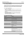
Guide to the MVI46-104S User Manual
Function
Introduction
Section to Read
Details
→
Start Here (page 9)
This Section introduces the customer to the
module. Included are: package contents,
system requirements, hardware installation, and
basic configuration.
→
Verifying
Communication
(page 53)
This section describes how to verify
communications with the network. Diagnostic
and Troubleshooting procedures.
(Must Do)
Verify Communication,
Diagnostic and
Troubleshooting
Diagnostics and
Troubleshooting
(page 43)
Reference
→
Product Specifications
Functional Overview
Product
Specifications
Glossary
Support, Service, and
Warranty
Index
ProSoft Technology, Inc.
September 4, 2008
Reference (page 57) These sections contain general references
Functional Overview associated with this product, Specifications, and
the Functional Overview.
(page 60)
→
Support, Service
and Warranty (page
83)
This section contains Support, Service and
Warranty information.
Index of chapters.
Page 7 of 93
MVI46-104S ♦ SLC Platform
IEC 60870-5-104 Slave Interface Module
Page 8 of 93
Start Here
ProSoft Technology, Inc.
September 4, 2008
Start Here
1
MVI46-104S ♦ SLC Platform
IEC 60870-5-104 Slave Interface Module
Start Here
In This Chapter
System Requirements ............................................................................. 9
Package Contents ................................................................................. 10
Install ProSoft Configuration Builder Software....................................... 10
Setting Jumpers .................................................................................... 12
Install the Module in the Rack ............................................................... 12
Connect your PC to the Processor ........................................................ 14
Download the Sample Program to the Processor.................................. 15
Connect your PC to the Module ............................................................ 17
Installing the MVI46-104S module requires a reasonable working knowledge of
the Rockwell Automation hardware, the MVI46-104S Module and the application
in which they will be used.
Caution: It is important that those responsible for implementation can complete the
application without exposing personnel, or equipment, to unsafe or inappropriate working
conditions. Safety, quality and experience are key factors in a successful installation.
1.1
System Requirements
The MVI46-104S module requires the following minimum hardware and software
components:
Rockwell Automation SLC 5/02 M0/M1 capable processors (or newer), with
compatible power supply and one free slot in the rack, for the MVI46-104S
module. The module requires 800mA of available power.
Rockwell Automation RSLogix 500 programming software.
Rockwell Automation RSLinx communication software
Pentium® II 500 MHz minimum. Pentium III 733 MHz (or better)
recommended
Supported operating systems:
o Microsoft® Windows 98
o Windows NT® (version 4 with SP4 or higher)
o Windows 2000
o Windows XP
32 Mbytes of RAM minimum, 64 Mbytes of RAM recommended
50 Mbytes of free hard disk space (or more based on application
requirements)
ProSoft Technology, Inc.
September 4, 2008
Page 9 of 93
MVI46-104S ♦ SLC Platform
IEC 60870-5-104 Slave Interface Module
Start Here
16-color VGA graphics adapter, 640 x 480 minimum resolution (256 Color
800 × 600 recommended)
CD-ROM drive
3.5 inch floppy disk drive
HyperTerminal or other terminal emulator program capable of file transfers
using Zmodem protocol.
1.2
Package Contents
The following components are included with your MVI46-104S module, and are
all required for installation and configuration.
Important: Before beginning the installation, please verify that all of the following items are
present.
Qty.
Part Name
Part Number
Part Description
1
MVI46-104S
Module
MVI46-104S
IEC 60870-5-104 Slave Interface Module
1
Cable
Cable #15, RS232
Null Modem
For RS232 Connection to the CFG Port
1
Cable
RJ45 to DB9 Male
Adapter
For DB9 Connection to Module's Port
1
inRAx
Solutions CD
Contains sample programs, utilities and
documentation for the MVI46-104S module.
If any of these components are missing, please contact ProSoft Technology
Support for replacement parts.
1.3
Install ProSoft Configuration Builder Software
You must install the ProSoft Configuration Builder (PCB) software in order to
configure the MVI46-104S module. You can always get the newest version of
ProSoft Configuration Builder from the ProSoft Technology web site.
To install ProSoft Configuration Builder from the ProSoft Web Site
1
2
Open your web browser and navigate to http://www.prosofttechnology.com/pcb
Click the Download Here link to download the latest version of ProSoft
Configuration Builder.
Page 10 of 93
ProSoft Technology, Inc.
September 4, 2008
Start Here
MVI46-104S ♦ SLC Platform
IEC 60870-5-104 Slave Interface Module
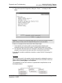
3
Choose "Save" or "Save File" when prompted. The following illustrations
show the file download prompt for two of the most common web browsers.
4
Make a note of the location where you saved the file, for example "Desktop",
or "My Documents", so you can start the installation program.
When the download is complete, locate and open the file, and then follow the
instructions on your screen to install the program.
5
If you do not have access to the Internet, you can install ProSoft Configuration
Builder from the ProSoft Solutions CD-ROM, included in the package with your
MVI46-104S module.
To install ProSoft Configuration Builder from the CD-ROM
1
2
3
4
Insert the ProSoft Solutions CD-ROM into the CD drive of your PC. Wait for
the startup screen to appear.
On the startup screen, click Product Documentation. This action opens an
explorer window.
Click to open the Utilities folder. This folder contains all of the applications
and files you will need to set up and configure your module.
Double-click the ProSoft Configuration Builder Setup program and follow the
instructions on your screen to install the software on your PC.
Note: Many of the configuration and maintenance procedures use files and other utilities on the
CD-ROM. You may wish to copy the files from the Utilities folder on the CD-ROM to a convenient
location on your hard drive.
ProSoft Technology, Inc.
September 4, 2008
Page 11 of 93
MVI46-104S ♦ SLC Platform
IEC 60870-5-104 Slave Interface Module
1.4
Start Here
Setting Jumpers
Note: The Setup Jumper acts as "write protection" for the module's flash memory. In "write
protected" mode, the Setup pins are not connected, and the module's firmware cannot be
overwritten. Do not jumper the Setup pins together unless you are directed to do so by ProSoft
Technical Support.
1.5
Install the Module in the Rack
If you have not already installed and configured your SLC processor and power
supply, please do so before installing the MVI46-104S module. Refer to your
Rockwell Automation product documentation for installation instructions.
Warning: You must follow all safety instructions when installing this or any other electronic
devices. Failure to follow safety procedures could result in damage to hardware or data, or even
serious injury or death to personnel. Refer to the documentation for each device you plan to
connect to verify that suitable safety procedures are in place before installing or servicing the
device.
After you have checked the placement of the jumpers, insert MVI46-104S into
the SLC™ chassis. Use the same technique recommended by Rockwell
Automation to remove and install SLC™ modules.
Warning: This module is not hot-swappable! Always remove power from the rack before
inserting or removing this module, or damage may result to the module, the processor, or other
connected devices.
1
Turn power OFF.
Page 12 of 93
ProSoft Technology, Inc.
September 4, 2008
Start Here
MVI46-104S ♦ SLC Platform
IEC 60870-5-104 Slave Interface Module
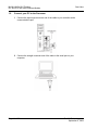
2
Align the module with the top and bottom guides, and slide it into the rack
until the module is firmly against the backplane connector.
3
4
With a firm but steady push, snap the module into place.
Check that the holding clips on the top and bottom of the module are securely
in the locking holes of the rack.
Make a note of the slot location. You will need to identify the slot in which the
module is installed in order for the sample program to work correctly. Slot
numbers are identified on the green circuit board (backplane) of the SLC
rack.
Turn power ON.
5
6
Note: If you insert the module improperly, the system may stop working, or may behave
unpredictably.
ProSoft Technology, Inc.
September 4, 2008
Page 13 of 93
MVI46-104S ♦ SLC Platform
IEC 60870-5-104 Slave Interface Module
1.6
Start Here
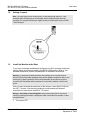
Connect your PC to the Processor
1
Connect the right-angle connector end of the cable to your controller at the
communications port.
2
Connect the straight connector end of the cable to the serial port on your
computer.
Page 14 of 93
ProSoft Technology, Inc.
September 4, 2008
Start Here
1.7
MVI46-104S ♦ SLC Platform
IEC 60870-5-104 Slave Interface Module
Download the Sample Program to the Processor
To download the sample program from RSLogix 500 to the SLC processor:
Note: The key switch on the front of the SLC processor must be in the REM position.
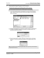
1
If you are not already online to the processor, open the Communications
menu, and then choose Download. RSLogix will establish communication
with the processor.
2
3
Click the Download button to transfer the sample program to the processor.
RSLogix will compile the program and transfer it to the processor. This
process may take a few minutes.
4
When the download is complete, RSLogix will open another confirmation
dialog box. Click Yes to switch the processor from Program mode to Run
mode.
Note: If you receive an error message during these steps, refer to your RSLogix documentation to
interpret and correct the error.
ProSoft Technology, Inc.
September 4, 2008
Page 15 of 93
MVI46-104S ♦ SLC Platform
IEC 60870-5-104 Slave Interface Module
Start Here
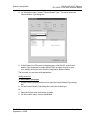
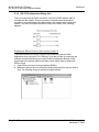
1.7.1 Configuring RSLinx
If RSLogix is unable to establish communication with the processor, follow these steps:
1
2
Open RSLinx.
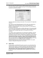
Open the Communications menu, and choose Configure Drivers.
This action opens the Configure Drivers dialog box.
Note: If the list of configured drivers is blank, you must first choose and configure a driver from the
Available Driver Types list. The recommended driver type to choose for serial communication with
the processor is "RS-232 DF1 Devices".
Page 16 of 93
ProSoft Technology, Inc.
September 4, 2008
Start Here
MVI46-104S ♦ SLC Platform
IEC 60870-5-104 Slave Interface Module
3
Click to select the driver, and then click Configure. This action opens the
Configure Allen-Bradley DF1 Communications Device dialog box.
4
Click the Auto-Configure button. RSLinx will attempt to configure your serial
port to work with the selected driver.
When you see the message "Auto Configuration Successful", click the OK
button to dismiss the dialog box.
5
Note: If the auto-configuration procedure fails, verify that the cables are connected correctly
between the processor and the serial port on your computer, and then try again. If you are still
unable to auto-configure the port, refer to your RSLinx documentation for further troubleshooting
steps.
1.8
Connect your PC to the Module
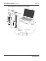
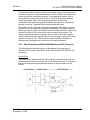
With the module securely mounted, connect your PC to the Configuration/Debug
port using an RJ45-DB-9 Serial Adapter Cable and a Null Modem Cable.
1
2
Attach both cables as shown.
Insert the RJ45 cable connector into the Configuration/Debug port of the
module.
ProSoft Technology, Inc.
September 4, 2008
Page 17 of 93
MVI46-104S ♦ SLC Platform
IEC 60870-5-104 Slave Interface Module
3
Start Here
Attach the other end to the serial port on your PC or laptop.
Page 18 of 93
ProSoft Technology, Inc.
September 4, 2008
Module Configuration
2
MVI46-104S ♦ SLC Platform
IEC 60870-5-104 Slave Interface Module
Module Configuration
In This Chapter
Installing and Configuring the Module ................................................... 20
Module Data .......................................................................................... 21
ProSoft Configuration Builder ................................................................ 22
[Backplane Configuration] ..................................................................... 26
[IEC-870-5-104]..................................................................................... 27
[IEC-870-5-104 IP Addresses]............................................................... 31
[IEC-870-5-104 Database]..................................................................... 32
[M_SP_NA_1 104]................................................................................. 34
[M_DP_NA_1 104] ................................................................................ 35
[M_ST_NA_1 104] ................................................................................. 35
[M_ME_NA_1 104] ................................................................................ 35
[M_ME_NB_1 104] ................................................................................ 36
[M_IT_NA_1 104] .................................................................................. 36
[C_SC_NA_1 104] ................................................................................. 36
[C_DC_NA_1 104]................................................................................. 37
[C_RC_NA_1 104]................................................................................. 37
[C_SE_NA_1 104] ................................................................................. 37
[C_SE_NB_1 104] ................................................................................. 38
Group Definition .................................................................................... 38
Download the Project to the Module...................................................... 39
This section contains the setup procedure, data and ladder logic requirements for
successful application of the MVI46-104S module. Each step in the setup
procedure is defined in order to simplify the use of the module. Go to the
Installing and Configuring the Module section to begin installing and
configuring the module. Additionally, this document contains a discussion on
configuring the module using the IEC8704S.CFG file. All configuration
information used by the module is stored in this file. Go to the Configuration File
section to begin setting up this file.
The document also contains a discussion of the data areas defined for the
module. These areas contain the read and write data from the module and status
related to the module. It is important to understand each element of the data
areas for proper application of the module. Go to the Module Data section for the
presentation of the data areas.
ProSoft Technology, Inc.
September 4, 2008
Page 19 of 93
MVI46-104S ♦ SLC Platform
IEC 60870-5-104 Slave Interface Module
Module Configuration
The ladder logic requirement section defines the minimum ladder logic required
to apply the module in a user application. The logic is simple to understand and
implement. Go to the Ladder Logic section for a complete discussion of the
ladder logic requirements.
2.1
Installing and Configuring the Module
The configuration process consists of the following steps.
1
Download the sample program to the processor.
Note: For most applications, the sample program will work without modification. We strongly
recommend setting up the module first with the sample program, before attempting to add the
module to an existing application or create a custom application.
Modify the module's configuration files to meet the needs of your application, and
copy the updated configuration to the module. Example configuration files are
provided on the CD-ROM. Refer to Modifying the Configuration File (page 24) for
more information on the configuration files.
First, define the module to the system. Select the I/O Configuration option from
the program screen. This displays the following dialog box:
Select the Other module from the list. This action opens the following dialog box.
Page 20 of 93
ProSoft Technology, Inc.
September 4, 2008
Module Configuration
MVI46-104S ♦ SLC Platform
IEC 60870-5-104 Slave Interface Module
Enter the module I/O card ID number as 12835, and then click OK. Double-click
the mouse on the module just added to the rack. Fill in the dialog box presented
as shown in the following example:
Click OK to apply these settings to the module. Then, close the I/O Configuration
dialog box.
Next, define the user defined data areas to hold the status and read and write
database areas. Edit the IEC8704S.CFG file now for the application to
implement. Use any text editor to set the values in the file. You must retain the
file name, IEC8704S.CFG.
The last step in the module setup is to add the ladder logic. If the example ladder
logic is used, adjust the ladder to fit the application. When the ladder example is
not used, copy the example ladder logic to your application and alter as
necessary.
The module is now set up and ready to be used with your application. Insert the
module in the rack and attach the serial communication cables. Download the
IEC8704S.CFG file to the module. Download the new application to the controller
and place the processor in run mode. If all the configuration parameters are set
correctly and the module is attached to a network, the module's Application LED
(APP LED) should remain off and the backplane activity LED (BP ACT) should
blink very rapidly. Refer to the Diagnostics and Troubleshooting section of this
manual you encounter errors. Attach a computer or terminal to
Debug/Configuration port on the module and look at the status of the module
using the Configuration/Debug Menu in the module.
2.2
Module Data
All data related to the MVI46-104S module is stored in a user defined data files
and the module's M1 file. Files should be defined for each data type to be used
with the module. Additionally, a file should be defined to hold the module status
data. The status data should be copied from the M1 file and placed in the
assigned status file. Input (monitor) data should be copied from the user file to
the M1 file and output (command) data should be copied from the user files to
the M1 file.
ProSoft Technology, Inc.
September 4, 2008
Page 21 of 93
MVI46-104S ♦ SLC Platform
IEC 60870-5-104 Slave Interface Module
2.3
Module Configuration
ProSoft Configuration Builder
ProSoft Configuration Builder (PCB) provides a quick and easy way to manage
module configuration files customized to meet your application needs. PCB is not
only a powerful solution for new configuration files, but also allows you to import
information from previously installed (known working) configurations to new
projects.
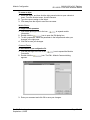
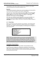
2.3.1 Set Up the Project
To begin, start ProSoft Configuration Builder. If you have used other Windows
configuration tools before, you will find the screen layout familiar. ProSoft
Configuration Builder's window consists of a tree view on the left, an information
pane and a configuration pane on the right side of the window. When you first
start ProSoft Configuration Builder, the tree view consists of folders for Default
Project and Default Location, with a Default Module in the Default Location
folder. The following illustration shows the ProSoft Configuration Builder window
with a new project.
Your first task is to add the MVI46-104S module to the project.
1
Use the mouse to select "Default Module" in the tree view, and then click the
right mouse button to open a shortcut menu.
Page 22 of 93
ProSoft Technology, Inc.
September 4, 2008
Module Configuration
MVI46-104S ♦ SLC Platform
IEC 60870-5-104 Slave Interface Module
2
On the shortcut menu, choose "Choose Module Type". This action opens the
Choose Module Type dialog box.
3
In the Product Line Filter area of the dialog box, select MVI46. In the Select
Module Type dropdown list, select MVI46-104S, and then click OK to save
your settings and return to the ProSoft Configuration Builder window.
The next task is to set the module parameters.
Adding a Module
To add a module to your project:
1
2
Double-click the Default Module icon to open the Choose Module Type dialog
box.
On the Choose Module Type dialog box, select the module type.
Or
1
2
Open the Project menu and choose Location.
On the Location menu, choose Add Module.
ProSoft Technology, Inc.
September 4, 2008
Page 23 of 93
MVI46-104S ♦ SLC Platform
IEC 60870-5-104 Slave Interface Module
Module Configuration
To add a module to a different location:
1
Right-click the Location folder and choose Add Module. A new module icon
appears.
Or
1
2
Select the Location icon.
From the Project menu, select Location, then select Add Module.
Adding a Project
To add a project to an existing project file:
1
2
Select the Default Project icon.
Choose Project from the Project menu, then choose Add Project. A new
project folder appears.
2.3.2 Set Module Parameters
Notice that the contents of the information pane and the configuration pane
changed when you added the MVI46-104S module to the project.
At this time, you may wish to rename the "Default Project" and "Default Location"
folders in the tree view.
Page 24 of 93
ProSoft Technology, Inc.
September 4, 2008
Module Configuration
MVI46-104S ♦ SLC Platform
IEC 60870-5-104 Slave Interface Module
To rename an object:
1
2
3
Select the object, and then click the right mouse button to open a shortcut
menu. From the shortcut menu, choose Rename.
Type the name to assign to the object.
Click away from the object to save the new name.
Module Entries
To configure module parameters
1
2
3
4
Click on the plus sign next to the icon
to expand module
information.
Double-click the
icon to open the Edit dialog box.
To edit a parameter, select the parameter in the left pane and make your
changes in the right pane.
Click OK to save your changes.
Comment Entries
To add comments to your configuration file:
1
2
3
Click the plus sign to the left of the
icon to expand the Module
Comments.
Double-click the
icon. The Edit - Module Comment dialog
appears.
Enter your comment and click OK to save your changes.
ProSoft Technology, Inc.
September 4, 2008
Page 25 of 93
MVI46-104S ♦ SLC Platform
IEC 60870-5-104 Slave Interface Module
Module Configuration
Printing a Configuration File
To print a configuration file:
1
2
3
4
2.4
Select the Module icon, and then click the right mouse button to open a
shortcut menu.
On the shortcut menu, choose View Configuration. This action opens the
View Configuration window.
On the View Configuration window, open the File menu, and choose Print.
This action opens the Print dialog box.
On the Print dialog box, choose the printer to use from the dropdown list,
select printing options, and then click OK.
[Backplane Configuration]
This section provides the module with a unique name, identifies the method of
failure for the communications for the module if the processor is not in run, and
describes how to initialize the module upon startup.
2.4.1 Module Name
0 to 80 characters
This parameter assigns a name to the module that can be viewed using the
configuration/debug port. Use this parameter to identify the module and the
configuration file.
2.4.2 Failure Flag Count
0 through 65535
This parameter specifies the number of successive transfer errors that must
occur before the communication ports are shut down. If the parameter is set to 0,
the communication ports will continue to operate under all conditions. If the value
is set larger than 0 (1 to 65535), communications will cease if the specified
number of failures occur.
2.4.3 Error Offset
0 to 3980, or -1 to disable
This parameter specifies the database location where to write status data.
2.4.4 Initialize Output Data
Initialize Output Data
:
0 #0=No, 1=Yes read output values from
#controller
Determines whether the module should read output values from the controller. 0
= No, 1 = Yes.
Page 26 of 93
ProSoft Technology, Inc.
September 4, 2008
Module Configuration
2.5
MVI46-104S ♦ SLC Platform
IEC 60870-5-104 Slave Interface Module
[IEC-870-5-104]
This section provides information required to configure a server application with
the module. Most entries contained within this section are self explanatory.
2.5.1 Use IP List
0 or 1
This parameter specifies if the IP address of the host connected to the system
will be validated. If the parameter is set to 0, any host may connect to the unit. If
the parameter is set to 1, only hosts in the IP list will be permitted to connect to
the unit.
2.5.2 Override StartDT
0 or 1
This parameter is used when testing the unit with a simulator or with a client unit
that does not meet the IEC 60870-5-104 specification. After the host connects to
the system, it will send a STARTDT.ACT U-format message to the unit to permit
the unit to start sending data. If the client does not support this requirement, set
the parameter to a value of 1. Set the parameter to 0 if the unit sends the
STARTDT.ACT message.
2.5.3 Clear Queue on Close
0 or 1
Use this command to define if the module will store the unacknowledged buffers
in the unit after the connection is closed. If the specification is to be followed, set
this parameter to 0 and the packets will be resent after a connection is made. If
you want to flush the packets after the connection is closed, set this parameter to
1 (this is not according to the specification).
2.5.4 t1 Timeout Set Value
1 to 255
This is the timeout of send or test ASDUs and is in units of seconds. After a
packet is sent from the unit, the client must acknowledge the packet within this
time interval or else the unit will close the connection.
2.5.5 t2 Timeout Set Value
1 to 255
This is a timeout of when to send an S-format message to the host to
acknowledge outstanding messages received. This parameter is in units of
seconds and must be less than the value set for t1.
ProSoft Technology, Inc.
September 4, 2008
Page 27 of 93
MVI46-104S ♦ SLC Platform
IEC 60870-5-104 Slave Interface Module
Module Configuration
2.5.6 t3 Timeout Set Value
1 to 255
This is the timeout to wait on an idle line before the unit will send a TestFr.Act
message. This value is in units of seconds.
2.5.7 k (maximum queue)
1 to 20
This parameter specifies the number of unacknowledged messages the unit will
buffer. This parameter must match that in the host. If the set number of buffers
are filled in the unit, no other messages will be sent until the host unit
acknowledges some or all the messages.
2.5.8 w (latest ack threshold)
1 to 20
This parameter must match that of the host unit and specifies the number of
messages the module will receive before sending an S-format sequence
acknowledge message when no I-format data is ready to send. It is
recommended to set this value to 2/3 the value of k.
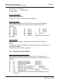
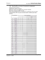
2.5.9 Time DB Offset
-1 or 0 to 3994
This parameter sets the location in the database where the module's current date
and time will be copied to.
Note: The following tables lists the 12 byte, data area placed in the database if the Time DB Offset
parameter is set to a value other than -1:
Byte
Length
Range
Description
0 to 1
2
0 to 59,999
Seconds and milliseconds
2
1
0 to 59
Minutes
3
1
0 to 23
Hour
4
1
Reserved
5
1
1 to 31
Day of the Month
6
1
1 to 12
Month
7 to 8
2
0 to 65,535
Year (four digit format, for example 2005)
9
1
10
1
11
1
Page 28 of 93
Reserved
0 or 1
Invalid Flag (0 = Valid, 1 = Invalid
Reserved
ProSoft Technology, Inc.
September 4, 2008
Module Configuration
MVI46-104S ♦ SLC Platform
IEC 60870-5-104 Slave Interface Module
2.5.10 Error Offset
0 to 3980, or -1 to disable
This parameter specifies the database location where to write status data.
2.5.11 Common Address of ASDU
0 to 65535
This parameter specifies the common address of the ASDU (section address) for
access to data in the module. There is only one value entered for access to all
data in the module.
2.5.12 Cyclic Data Transmission
0 to 2^32
This parameter defines the number of milliseconds between cyclic updates. The
range of values for this parameter permit update times of 1 millisecond to 5
minutes. If the parameter is set to 0, cyclic data reporting will be disabled.
2.5.13 Select/Operate Timeout
0 to 2^32
This parameter sets the number of milliseconds after a select command is
received in which to wait for a valid execute command. The range of values for
this parameter permit times of 1 millisecond to 30 seconds. If the parameter is
set to 0, the feature will be disabled.
2.5.14 Use ACTTERM with Setpoint
1 or 0
This parameter determines if an ACTTERM will be sent. If the parameter is set to
1, then setpoint commands will issue an ACTTERM when the command is
complete. If the parameter is set to 0, ACTCON is the last response to a setpoint
command.
2.5.15 Use ACTTERM with Step
1 or 0
This parameter determines if an ACTTERM will be sent. If the parameter is set to
1, then step commands will issue an ACTTERM when the command is complete.
If the parameter is set to 0, ACTCON is the last response to a step command.
ProSoft Technology, Inc.
September 4, 2008
Page 29 of 93
MVI46-104S ♦ SLC Platform
IEC 60870-5-104 Slave Interface Module
Module Configuration
2.5.16 Event Scan Delay
Event Scan delay
:
1 #MSec between event scanning (0-65535)
#0=Disable
If set to 0, the feature will be disabled and the module will not generate any
events. If set from 1 to 65535, the parameter represents the number of
milliseconds between event scanning. This parameter defines how often the
program will scan for new events in the databases.
2.5.17 M_SP_NA Scan Events
M_SP_NA Scan Events :
1 #0=No scanning, 1=scan for events
Determines if events of this point type will be generated by the module. If 0, then
events will not be generated. If 1, events will be scanned and generated on
change.
2.5.18 M_SP_NA Time Type
M_SP_NA Time Type
:
2 #0=None, 2=CP56 time
This parameters defines the time format used with data events. 0=None and
2=CP56 time formats.
2.5.19 M_DP_NA Scan Events
M_DP_NA Scan Events :
1 #0=No scanning, 1=scan for events
Determines if events of this point type will be generated by the module. If 0, then
events will not be generated. If 1, events will be scanned and generated on
change.
2.5.20 M_DP_NA Time Type
M_DP_NA Time Type
:
2 #0=None, 2=CP56 time
This parameters defines the time format used with data events. 0=None and
2=CP56 time formats.
2.5.21 M_ST_NA Scan Events
M_ST_NA Scan Events :
1 #0=No scanning, 1=scan for events
Determines if events of this point type will be generated by the module. If 0, then
events will not be generated. If 1, events will be scanned and generated on
change.
2.5.22 M_ST_NA Time Type
M_ST_NA Time Type
:
2 #0=None, 2=CP56 time
This parameters defines the time format used with data events. 0=None and
2=CP56 time formats.
Page 30 of 93
ProSoft Technology, Inc.
September 4, 2008
Module Configuration
MVI46-104S ♦ SLC Platform
IEC 60870-5-104 Slave Interface Module
2.5.23 M_ME_NA Scan Events
M_ME_NA Scan Events :
1 #0=No scanning, 1=scan for events
Determines if events of this point type will be generated by the module. If 0, then
events will not be generated. If 1, events will be scanned and generated on
change.
2.5.24 M_ME_NA Time Type
M_ME_NA Time Type
:
2 #0=None, 2=CP56 time
This parameter defines the time format used with data events. 0=None and
2=CP56 time formats.
2.5.25 M_ME_NB Scan Events
M_ME_NB Scan Events :
1 #0=No scanning, 1=scan for events
Determines if events of this point type will be generated by the module. If 0, then
events will not be generated. If 1, events will be scanned and generated on
change.
2.5.26 M_ME_NB Time Type
M_ME_NB Time Type
:
2 #0=None, 2=CP56 time
This parameters defines the time format used with data events. 0=None and
2=CP56 time formats.
2.5.27 M_IT_NA Time Type
M_IT_NA Time Type
:
2 #0=None, 2=CP56 time
This parameters defines the time format used with data events. 0=None and
2=CP56 time formats.
2.6
[IEC-870-5-104 IP Addresses]
This section enters the IP addresses for the hosts to connect to this unit. The unit
will only accept connections from hosts listed here. This list may contain up to 10
entries between the START and END labels. The address must start in column 1,
and must be entered in standard dot notation.
The following is an example of the [IEC-870-5-104 IP Addresses] section:
[IEC-870-5-104 IP ADDRESSES]
START
192.168.0.207
192.168.0.203
192.168.0.61
END
ProSoft Technology, Inc.
September 4, 2008
Page 31 of 93
MVI46-104S ♦ SLC Platform
IEC 60870-5-104 Slave Interface Module
2.7
Module Configuration
[IEC-870-5-104 Database]
This section describes the [IEC-870-5-104 Database] section.
Each parameter is described below. Edit the configuration file according to the
needs of your application.
2.7.1 Short Pulse Time
Short Pulse Time
:
2000 #MSec for short pulse command
This parameter defines the number of milliseconds to be associated with a short
pulse command. The valid range of numbers for this parameter are 0 to
2,147,483,647. Range is 0 to 2^31-1.
2.7.2 Long Pulse Time
Long Pulse Time
:
10000 #MSec for long pulse command
This parameter defines the number of milliseconds to be associated with a long
pulse command. The valid range of numbers for this parameter are 0 to
2,147,483,647. Range is 0 to 2^31-1
2.7.3 M_SP_NA Point Count
M_SP_NA point count :
10 #Number of monitored single-points
This parameter specifies the number of point values assigned in monitored
single-point database. Range is 0 to 1000.
2.7.4 M_DP_NA Point Count
M_DP_NA point count :
10 #Number of monitored dual-points
This parameter specifies the number of point values assigned in monitored dualpoint database. Rang is 0 to 1000.
2.7.5 M_ST_NA Point Count
M_ST_NA point count :
10 #Number of monitored step-points
This parameter specifies the number of point values assigned in monitored steppoint database. Range is 0 to 1000.
2.7.6 M_ME_NA Point Count
M_ME_NA point count :
10 #Number of monitored normalized-points
This parameter specifies the number of point values assigned in monitored
normalized-point database. Range is 0 to 1000.
Page 32 of 93
ProSoft Technology, Inc.
September 4, 2008
Module Configuration
MVI46-104S ♦ SLC Platform
IEC 60870-5-104 Slave Interface Module
2.7.7 M_ME_NB Point Count
M_ME_NB point count :
10 #Number of monitored scaled-points
This parameter specifies the number of point values assigned in monitored
scaled-point database. Range is 0 to 1000.
2.7.8 M_IT_NA Point Count
M_IT_NA point count :
10 #Number of monitored counter-points
This parameter specifies the number of point values assigned in monitored
counter-point database. Range is 0 to 1000.
2.7.9 C_SC_NA Point Count
C_SC_NA point count :
10 #Number of command single-points
This parameter specifies the number of point values assigned in command
single-point database. Range is 0 to 1000.
2.7.10 C_DC_NA Point Count
C_DC_NA point count :
10 #Number of command dual-points
This parameter specifies the number of point values assigned in command dualpoint database. Range is 0 to 1000.
2.7.11 C_RC_NA Point Count
C_RC_NA point count :
10 #Number of command step-points
This parameter specifies the number of point values assigned in command steppoint database. Range is 0 to 1000.
2.7.12 C_SE_NA Point Count
C_SE_NA point count :
10 #Number of command normalized-points
This parameter specifies the number of point values assigned in command
normalized-point database. Range is 0 to 1000.
2.7.13 C_SE_NB Point Count
C_SE_NB point count :
10 #Number of command scaled-points
This parameter specifies the number of point values assigned in command
scaled-point database. Range is 0 to 1000.
ProSoft Technology, Inc.
September 4, 2008
Page 33 of 93
MVI46-104S ♦ SLC Platform
IEC 60870-5-104 Slave Interface Module
Module Configuration
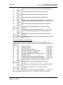
2.7.14 M_ME_NA Parameter Offset
M_ME_NA Parameter Offset :
2000 #M_ME_NA IOA offset for parameter data
This parameter specifies the IOA offset to the parameter data for the normalized
parameter data. The value entered is added to the Information Object Address
for the associated point to compute the parameter IOA address. When the
M_ME_NA or M_ME_NB points are polled (e.g, with a group interrogation
request), the module will also include parameter points in the response.
For each monitored point, there will be three parameter points:
Point
Value
Threshold
Determined by the deadband set in the configuration file or
altered by the write command.
Low
Last reported event value - threshold.
High
Last reported event value + threshold.
2.7.15 M_ME_NB Parameter Offset
M_ME_NB Parameter Offset
:
2000 #M_ME_NB IOA offset for parameter data
This parameter specifies the IOA offset to the parameter data for the scaled
parameter data. The value entered is added to the Information Object Address
for the associated point to compute the parameter IOA address.
For each monitored point, there will be three parameter points:
Point
Value
Threshold
Determined by the deadband set in the configuration file or
altered by the write command.
Low
Last reported event value - threshold.
High
Last reported event value + threshold.
For example, for a M_ME_NA point with an Information Object Address of 503,
the associated parameter point would have an IOA of 2503 (for a configured
parameter offset of 2000).
2.8
[M_SP_NA_1 104]
This section defines the monitored single-point database for the server device
emulated. This information is sourced from the database and is transferred to the
remote client unit. Each point in the database occupies 1 bit. (1 = On, 0 = Off
state).
This section takes the following parameters:
Point #
DB Address
Group(s)
Each point is one bit and the DB address value corresponds to the bit offset in
the database.
Page 34 of 93
ProSoft Technology, Inc.
September 4, 2008
Module Configuration
2.9
MVI46-104S ♦ SLC Platform
IEC 60870-5-104 Slave Interface Module
[M_DP_NA_1 104]
This section defines the monitored dual-point database for the server device
emulated. This information is sourced from the database and is transferred to the
remote client unit. Each point in the database occupies two bits. (00 =
intermediate, 01 = off, 10 = on and 11 = intermediate).
This section takes the following parameters:
Point #:
DB Address:
Group(s):
Each point is two bits and the DB address value corresponds to the bit offset in
the database.
2.10
[M_ST_NA_1 104]
This section defines the monitored step database for the server device emulated.
This information is sourced from the database and is transferred to the remote
client unit. Each point in the database occupies one byte.
This section takes the following parameters:
Point #:
DB Address:
Group(s):
Each point is one byte and the DB Address value corresponds to the byte offset
in the database.
2.11
[M_ME_NA_1 104]
This section defines the monitored measured value, normalized database for the
server device emulated. This information is sourced from the database and is
transferred to the remote client unit. Each point occupies a word position in the
database. The IOA for the parameters are for each object and are determined by
adding the Point # below to the value of the M_ME_NA parameter offset
parameter set in the previous section.
This section takes the following parameters:
Point #:
DB Address:
Group(s):
Default Deadband:
Each point is one word and the DB Address value corresponds to the word offset
in the database.
ProSoft Technology, Inc.
September 4, 2008
Page 35 of 93
MVI46-104S ♦ SLC Platform
IEC 60870-5-104 Slave Interface Module
2.12
Module Configuration
[M_ME_NB_1 104]
This section defines the monitored measured value, scaled database for the
server device emulated. This information is sourced from the database and is
transferred to the remote client unit. Each point occupies a word position in the
database. The IOA for the parameters for each object are determined by adding
the Point # below to the value of the M_ME_NB parameter offset parameter set
in the previous section.
This section takes the following parameters:
Point #:
DB Address:
Group(s):
Default Deadband:
Each point is one word and the DB Address value corresponds to the word offset
in the database.
2.13
[M_IT_NA_1 104]
This section defines the monitored integrated totals (counter) database for the
server emulated. This information is sourced from the database and is
transferred to the remote client unit. Each point occupies two words in the
database (4 bytes).
This section takes the following parameters:
Point #:
DB Address:
Group(s):
Each point is two words and the DB Address value corresponds to the doubleword offset in the database.
2.14
[C_SC_NA_1 104]
This section defines the single point command database for the server emulated.
This information is sourced from the remote client and is transferred to the
database. Each point occupies a single bit position in the database. You can
associate a command with a monitored single-point database value to coordinate
the command/monitor operation. You must enter the correct Monitor Point # and
Monitor DB Address values in the table. If the Require Select parameter is not
set to zero, a select command must be received before an execute command will
be processed.
This section takes the following parameters:
Point #:
DB Address:
Monitor Point #:
Monitor DB Addr:
Require Select:
Each point is one bit and the DB Address value corresponds to the bit offset in
the database.
Page 36 of 93
ProSoft Technology, Inc.
September 4, 2008
Module Configuration
2.15
MVI46-104S ♦ SLC Platform
IEC 60870-5-104 Slave Interface Module
[C_DC_NA_1 104]
This section defines the double point command database for the server
emulated. This information is sourced from the remote client and is transferred to
the database. Each point occupies two bits in the database. You can associate a
command with a monitored double point database value to coordinate the
command/monitor operation. You must enter the correct Monitor Point # and
Monitor DB Addr values in the table. If the Require Select parameter is not set to
zero, a select command must be received before an execute command will be
processed.
This section takes the following parameters:
Point #:
DB Address:
Monitor Point #:
Monitor DB Addr:
Require Select:
Each point is two bits and the DB Address value corresponds to the bit offset in
the database.
2.16
[C_RC_NA_1 104]
This section defines the step command database for the server emulated. This
information is sourced from the remote client and is transferred to the database.
Each point occupies a byte in the database. The control value can be associated
with a monitored point as described in the previous example.
This section takes the following parameters:
Point #:
DB Address:
Monitor Point #:
Monitor DB Addr:
Each point is one byte and the DB Address value corresponds to the byte offset
in the database.
2.17
[C_SE_NA_1 104]
This section defines the normalized setpoint database for the server emulated.
This information is sourced from the remote client and is transferred to the
database. Each point occupies a word position in the database. You can
associate a command with a monitored normalized database value to coordinate
the command/monitor operation. You must enter the correct Monitor Point # and
Monitor DB Addr values in the table. If the Require Select parameter is not set to
zero, a select command must be received before an execute command will be
processed.
This section takes the following parameters:
Point #:
DB Address:
ProSoft Technology, Inc.
September 4, 2008
Page 37 of 93
MVI46-104S ♦ SLC Platform
IEC 60870-5-104 Slave Interface Module
Module Configuration
Monitor Point #:
Monitor DB Addr:
Require Select:
Each point is one word and the DB Address value corresponds to the word offset
in the database.
2.18
[C_SE_NB_1 104]
This section defines the scaled setpoint database for the server emulated. This
information is sourced from the remote client and is transferred to the database.
You can associate a command with a monitored scaled database value to
coordinate the command/monitor operation. You must enter the correct Monitor
Point # and Monitor DB Addr values in the table. If the Require Select parameter
is not set to zero, a select command must be received before an execute
command will be processed.
This section takes the following parameters:
Point #:
DB Address:
Monitor Point #:
Monitor DB Addr:
Require Select:
Each point is one word and the DB Address value corresponds to the word offset
in the database.
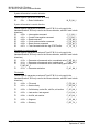
2.19
Group Definition
One aspect of the point configuration database that leads to confusion is the
group definition field. This assignment for each point assigns a point to one or
more interrogation groups. Use of interrogation groups permits the controlling
unit to interface with a specific set of data. Refer to the IEC 60870-5-104
standard for a full discussion of interrogation groups. A specific group, Periodic
data group, reports data points on a set frequency. The frequency is set in the
Cyclic Data Transmission parameter in the configuration file. Remember that a
point can be assigned to more than one group:
Group Code
Description
0x00000001
Interrogated by general interrogation (station or global)
0x00000002
Interrogated by group 1 interrogation
0x00000004
Interrogated by group 2 interrogation
0x00000008
Interrogated by group 3 interrogation
0x00000010
Interrogated by group 4 interrogation
0x00000020
Interrogated by group 5 interrogation
0x00000040
Interrogated by group 6 interrogation
0x00000080
Interrogated by group 7 interrogation
0x00000100
Interrogated by group 8 interrogation
0x00000200
Interrogated by group 9 interrogation
Page 38 of 93
ProSoft Technology, Inc.
September 4, 2008
Module Configuration
MVI46-104S ♦ SLC Platform
IEC 60870-5-104 Slave Interface Module
Group Code
Description
0x00000400
Interrogated by group 10 interrogation
0x00000800
Interrogated by group 11 interrogation
0x00001000
Interrogated by group 12 interrogation
0x00002000
Interrogated by group 13 interrogation
0x00004000
Interrogated by group 14 interrogation
0x00008000
Interrogated by group 15 interrogation
0x00010000
Interrogated by group 16 interrogation
0x00020000
Interrogated by general counter request
0x00040000
Interrogated by group 1 counter request
0x00080000
Interrogated by group 2 counter request
0x00100000
Interrogated by group 3 counter request
0x00200000
Interrogated by group 4 counter request
0x40000000
Disable event scanning of this point
0x80000000
Periodic/cyclic data returned from unit
If the highest bit (bit 31) is set, data will be produced by the driver for the
specified point at the rate set for periodic data generation. Bit 30 (0x40000000)
enables scanning of this point for event generation. If the bit is clear and the data
type is set for scanning, events will be generated for the point. If the bit is set,
events will not be generated for the point. This feature can be used to select
which points will generate events for the controlling station and can get rid of
event data that is not important to the application.
2.20
Download the Project to the Module
In order for the module to use the settings you configured, you must download
(copy) the updated Project file from your PC to the module.
To Download the Project File
1
2
In the tree view in ProSoft Configuration Builder, click once to select the
MVI46-104S module.
Open the Project menu, and then choose Module / Download. The program
will scan your PC for a valid com port (this may take a few seconds). When
PCB has found a valid com port, the following dialog box will open.
ProSoft Technology, Inc.
September 4, 2008
Page 39 of 93
MVI46-104S ♦ SLC Platform
IEC 60870-5-104 Slave Interface Module
3
Module Configuration
Choose the com port to use from the dropdown list, and then click the
Download button.
The module will perform a platform check to read and load its new settings.
When the platform check is complete, the status bar in ProSoft Configuration
Builder will be updated with the message "Module Running".
Page 40 of 93
ProSoft Technology, Inc.
September 4, 2008
Ladder Logic
3
MVI46-104S ♦ SLC Platform
IEC 60870-5-104 Slave Interface Module
Ladder Logic
Ladder logic is required for application of the MVI46-104S module. Tasks that
must be handled by the ladder logic are module data transfer, special block
handling and status data receipt. Additionally, a power-up handler may be
needed to handle the initialization of the module's data and to clear any
processor fault conditions.
The sample ladder logic, on the ProSoft Solutions CD-ROM, is extensively
commented, to provide information on the purpose and function of each rung. For
most applications, the sample ladder will work without modification.
ProSoft Technology, Inc.
September 4, 2008
Page 41 of 93
MVI46-104S ♦ SLC Platform
IEC 60870-5-104 Slave Interface Module
Page 42 of 93
Ladder Logic
ProSoft Technology, Inc.
September 4, 2008
Diagnostics and Troubleshooting
4
MVI46-104S ♦ SLC Platform
IEC 60870-5-104 Slave Interface Module
Diagnostics and Troubleshooting
In This Chapter
Reading Status Data from the Module .................................................. 43
LED Status Indicators............................................................................ 53
The module provides information on diagnostics and troubleshooting in the
following forms:
Status data values are transferred from the module to the processor.
Data contained in the module can be viewed through the
Configuration/Debug port attached to a terminal emulator.
LED status indicators on the front of the module provide information on the
module's status.
4.1
Reading Status Data from the Module
The MVI46-104S module returns a 26-word Status Data block that can be used
to determine the module's operating status. This data can be located in the
module's database at registers at the location specified in the configuration. This
data is transferred to the SLC processor M1 file continuously. For a complete
listing of the status data object, refer to the Module Set Up Guide section.
4.1.1 Required Hardware
You can connect directly from your computer's serial port to the serial port on the
module to view configuration information, perform maintenance, and send
(upload) or receive (download) configuration files.
ProSoft Technology recommends the following minimum hardware to connect
your computer to the module:
80486 based processor (Pentium preferred)
1 megabyte of memory
At least one UART hardware-based serial communications port available.
USB-based virtual UART systems (USB to serial port adapters) often do not
function reliably, especially during binary file transfers, such as when
uploading/downloading configuration files or module firmware upgrades.
A null modem serial cable.
ProSoft Technology, Inc.
September 4, 2008
Page 43 of 93
MVI46-104S ♦ SLC Platform
IEC 60870-5-104 Slave Interface Module
Diagnostics and Troubleshooting
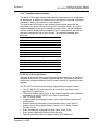
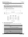
4.1.2 The Configuration/Debug Menu
The Configuration and Debug menu for this module is arranged as a tree
structure, with the Main Menu at the top of the tree, and one or more sub-menus
for each menu command. The first menu you see when you connect to the
module is the Main menu.
Because this is a text-based menu system, you enter commands by typing the
command letter from your computer keyboard in the diagnostic window in
ProSoft Configuration Builder (PCB). The module does not respond to mouse
movements or clicks. The command executes as soon as you press the
command letter — you do not need to press [Enter]. When you type a command
letter, a new screen will be displayed in your terminal application.
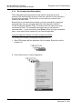
Using the Diagnostic Window in ProSoft Configuration Builder
To connect to the module's Configuration/Debug serial port:
1
Start PCB program with the application file to be tested. Right click over the
module icon.
2
On the shortcut menu, choose Diagnostics.
Page 44 of 93
ProSoft Technology, Inc.
September 4, 2008
Diagnostics and Troubleshooting
3
MVI46-104S ♦ SLC Platform
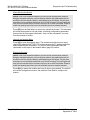
IEC 60870-5-104 Slave Interface Module
This action opens the Diagnostics dialog box. Press "?" to display the Main
Menu.
Important: The illustrations of configuration/debug menus in this section are intended as a general
guide, and may not exactly match the configuration/debug menus in your own module.
If there is no response from the module, follow these steps:
1
2
Verify that the null modem cable is connected properly between your
computer's serial port and the module. A regular serial cable will not work.
On computers with more than one serial port, verify that your communication
program is connected to the same port that is connected to the module.
If you are still not able to establish a connection, contact ProSoft Technology for
assistance.
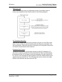
Navigation
All of the sub-menus for this module contain commands to redisplay the menu or
return to the previous menu. You can always return from a sub-menu to the next
higher menu by pressing [M] on your keyboard.
The organization of the menu structure is represented in simplified form in the
following illustration:
ProSoft Technology, Inc.
September 4, 2008
Page 45 of 93
MVI46-104S ♦ SLC Platform
IEC 60870-5-104 Slave Interface Module
Diagnostics and Troubleshooting
The remainder of this section shows you the menus available for this module,
and briefly discusses the commands available to you.
Keystrokes
The keyboard commands on these menus are almost always non-case sensitive.
You can enter most commands in lower case or capital letters.
The menus use a few special characters ([?], [-], [+], [@]) that must be entered
exactly as shown. Some of these characters will require you to use the [Shift],
[Ctrl] or [Alt] keys to enter them correctly. For example, on US English
keyboards, enter the [?] command as [Shift][/].
Also, take care to distinguish capital letter [I] from lower case letter [l] (L) and
number [1]; likewise for capital letter [O] and number [0]. Although these
characters look nearly the same on the screen, they perform different actions on
the module.
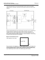
4.1.3 Main Menu
When you first connect to the module from your computer, your terminal screen
will be blank. To activate the main menu, press the [?] key on your computer's
keyboard. If the module is connected properly, the following menu will appear on
your terminal screen:
Caution: Some of the commands available to you from this menu are designed for advanced
debugging and system testing only, and can cause the module to stop communicating with the
processor or with other devices, resulting in potential data loss or other failures. Only use these
commands if you are specifically directed to do so by ProSoft Technology Technical Support staff.
Some of these command keys are not listed on the menu, but are active nevertheless. Please be
careful when pressing keys so that you do not accidentally execute an unwanted command.
Viewing Block Transfer Statistics
Press [B] from the Main Menu to view the Block Transfer Statistics screen.
Use this command to display the configuration and statistics of the backplane
data transfer operations between the module and the processor. The information
on this screen can help determine if there are communication problems between
the processor and the module.
Page 46 of 93
ProSoft Technology, Inc.
September 4, 2008
Diagnostics and Troubleshooting
MVI46-104S ♦ SLC Platform
IEC 60870-5-104 Slave Interface Module
Tip: To determine the number of blocks transferred each second, mark the numbers displayed at a
specific time. Then some seconds later activate the command again. Subtract the previous
numbers from the current numbers and divide by the quantity of seconds passed between the two
readings.
Viewing Module Configuration
Press [C] to view the Module Configuration screen.
Use this command to display the current configuration and statistics for the
module.
Opening the Database Menu
Press [D] to open the Database View menu. Use this menu command to view the
current contents of the module's database.
Opening the ICE 60870-5-104 Menu
Press [I] to view all data associated with the IEC 60870-5-104 server driver.
Receiving the Configuration File
Press [R] to download (receive) the current configuration file from the module.
For more information on receiving and sending configuration files, please see
Uploading and Downloading the Configuration File.
Sending the Configuration File
Press [S] to upload (send) an updated configuration file to the module. For more
information on receiving and sending configuration files, please see Uploading
and Downloading the Configuration File.
Viewing Version Information
Press [V] to view Version information for the module.
Use this command to view the current version of the software for the module, as
well as other important values. You may be asked to provide this information
when calling for technical support on the product.
Values at the bottom of the display are important in determining module
operation. The Program Scan Counter value is incremented each time a
module's program cycle is complete.
Tip: Repeat this command at one-second intervals to determine the frequency of program
execution.
ProSoft Technology, Inc.
September 4, 2008
Page 47 of 93
MVI46-104S ♦ SLC Platform
IEC 60870-5-104 Slave Interface Module
Diagnostics and Troubleshooting
Warm Booting the Module
Caution: Some of the commands available to you from this menu are designed for advanced
debugging and system testing only, and can cause the module to stop communicating with the
processor or with other devices, resulting in potential data loss or other failures. Only use these
commands if you are specifically directed to do so by ProSoft Technology Technical Support staff.
Some of these command keys are not listed on the menu, but are active nevertheless. Please be
careful when pressing keys so that you do not accidentally execute an unwanted command.
Press [W] from the Main Menu to warm boot (restart) the module. This command
will cause the program to exit and reload, refreshing configuration parameters
that must be set on program initialization. Only use this command if you must
force the module to re-boot.
Opening the Network Menu
Press [@] to open the network menu. The network menu allows you to send,
receive and view the WATTCP.CFG file that contains the IP, gateway and other
network specification information. You can find more information about the
commands on this menu in the Network Menu (page 52) section.
Exiting the Program
Caution: Some of the commands available to you from this menu are designed for advanced
debugging and system testing only, and can cause the module to stop communicating with the
processor or with other devices, resulting in potential data loss or other failures. Only use these
commands if you are specifically directed to do so by ProSoft Technology Technical Support staff.
Some of these command keys are not listed on the menu, but are active nevertheless. Please be
careful when pressing keys so that you do not accidentally execute an unwanted command.
Press [Esc] to restart the module and force all drivers to be loaded. The module
will use the configuration stored in the module's Flash ROM to configure the
module.
Page 48 of 93
ProSoft Technology, Inc.
September 4, 2008
Diagnostics and Troubleshooting
MVI46-104S ♦ SLC Platform
IEC 60870-5-104 Slave Interface Module
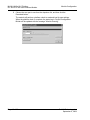
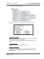
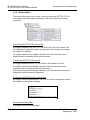
4.1.4 IEC-870-5-104 Server Menu
Press [I] from the main menu to display the IEC-870-5-104 Server Menu.
Viewing Server Configuration
Press [C] to view configuration information for the server. Use this command to
confirm that the module is correctly configured.
To change module configuration, edit and transfer the configuration file to the
module.
Viewing Program Status
Press [E] to view the error/status data for the module.
Viewing a List of Valid Hosts
Press [I] the list of IP addresses the module will accept connections from. This
list is only used if the module configuration parameter, Use IP List, is set to a
value other than 0.
ProSoft Technology, Inc.
September 4, 2008
Page 49 of 93
MVI46-104S ♦ SLC Platform
IEC 60870-5-104 Slave Interface Module
Diagnostics and Troubleshooting
Returning to the Main Menu
Press [M] to return to the Main Menu.
Viewing Data Type Setup
To view setup information for each data type, press the matching key from the
Menu.
Key
Data Type
1
M_SP_NA
2
M_DP_NA
3
M_ST_NA
4
M_ME_NA
5
M_ME_NB
6
M_IT_NA
7
C_SC_NA
8
C_DC_NA
Page 50 of 93
Screen Example
ProSoft Technology, Inc.
September 4, 2008
Diagnostics and Troubleshooting
Key
Data Type
9
C_RC_NA
0
C_SE_NA
Shift 1
C_SE_NB
Shift 4
C_SE_NC
MVI46-104S ♦ SLC Platform
IEC 60870-5-104 Slave Interface Module
Screen Example
Viewing IEC 60870 Database Configuration
Press [@] to view the database size configuration information.
ProSoft Technology, Inc.
September 4, 2008
Page 51 of 93
MVI46-104S ♦ SLC Platform
IEC 60870-5-104 Slave Interface Module
Diagnostics and Troubleshooting
4.1.5 Network Menu
The network menu allows you to send, receive and view the WATTCP.CFG file
that contains the IP and gateway addresses, and other network specification
information.
Transferring WATTCP.CFG to the module
Press [R] to transfer a new WATTCP.CFG file from the PC to the module. Use
this command to change the network configuration for the module (for example,
the module's IP address).
Press [Y] to confirm the file transfer, and then follow the instructions on the
terminal screen to complete the file transfer process.
Transferring WATTCP.CFG to the PC
Press [S] to transfer the WATTCP.CFG file from the module to your PC.
Press [Y] to confirm the file transfer, and then follow the instructions on the
terminal screen to complete the file transfer process.
After the file has been successfully transferred, you can open and edit the file to
change the module's network configuration.
Viewing the WATTCP.CFG file on the module
Press [V] to view the module's WATTCP.CFG file. Use this command to confirm
the module's current network settings.
Returning to the Main Menu
Press [M] to return to the Main Menu.
Page 52 of 93
ProSoft Technology, Inc.
September 4, 2008
Diagnostics and Troubleshooting
4.2
MVI46-104S ♦ SLC Platform
IEC 60870-5-104 Slave Interface Module
LED Status Indicators
The LEDs indicate the module's operating status as follows:
ProSoft
Module
Color
Status
Indication
CFG
Green
On
Data is being transferred between the module and a remote
terminal using the Configuration/Debug port.
Off
No data is being transferred on the Configuration/Debug
port.
P1
Green
On
Not used in this application
Off
Not used in this application
P2
Green
On
Not used in this application
Off
Not used in this application
Off
The MVI46-104S is working normally.
On
The MVI46-104S module program has recognized a
communication error on one of its ports.
On
The LED is on when the module is performing a write
operation on the backplane.
Off
The LED is off when the module is performing a read
operation on the backplane. Under normal operation, the
LED should blink rapidly on and off.
Off
The card is not receiving any power and is not securely
plugged into the rack.
Green
The module is operating normally.
Red
The program has detected an error or is being configured. If
the LED remains red for over 10 seconds, the program has
probably halted.
Off
The battery voltage is OK and functioning.
On
The battery voltage is low or battery is not present. Allow
battery to charge by keeping module plugged into rack for 24
hours. If BAT LED still does not go off, contact ProSoft
Technology, as this is not a user serviceable item.
APP
BP ACT
OK
BAT
Amber
Amber
Red/
Green
Red
If the APP, BP ACT and OK LEDs blink at a rate of every one-second, this
indicates a serious problem with the module. Call ProSoft Technology support to
arrange for repairs.
In addition to these LEDs, the module contains two LEDs under the module's
door. The LED on the left (green) displays the link status. If the module is
connected properly to a Hub, this LED should be illuminated. The LED on the
right (amber) is the data indication LED. Whenever the module is sending or
receiving data on the Ethernet interface, this LED will be illuminated.
ProSoft Technology, Inc.
September 4, 2008
Page 53 of 93
MVI46-104S ♦ SLC Platform
IEC 60870-5-104 Slave Interface Module
Diagnostics and Troubleshooting
4.2.1 Ethernet LED Indicators
LED
State
Description
Data
Off
No activity on the port.
Green Flash
The port is either actively transmitting or receiving data.
Off
No connection to hub or network is detected.
Green Solid
Connected to hub or network correctly. This is the normal
operating state.
Link
4.2.2 Clearing a Fault Condition
Typically, if the OK LED on the front of the module turns red for more than ten
seconds, a hardware problem has been detected in the module, or the program
has exited.
To clear the condition, follow these steps:
1
2
3
4
5
6
Turn off power to the rack
Remove the card from the rack
Verify that all jumpers are set correctly
If the module requires a Compact Flash card, verify that the card is installed
correctly
Re-insert the card in the rack and turn the power back on
Verify the configuration data being transferred to the module from the SLC
processor.
If the module's OK LED does not turn green, verify that the module is inserted
completely into the rack. If this does not cure the problem, contact ProSoft
Technology Support.
4.2.3 Troubleshooting
Use the following troubleshooting steps if you encounter problems when the
module is powered up. If these steps do not resolve your problem, please contact
ProSoft Technology Technical Support.
Processor Errors
Problem Description
Steps to take
Processor Fault
Verify that the module is plugged into the slot that has been configured
for the module.
Verify that the slot in the rack configuration has been set up correctly in
the ladder logic.
Processor I/O LED
flashes
Page 54 of 93
This indicates a problem with backplane communications. Verify that all
modules in the rack are configured in the ladder logic.
ProSoft Technology, Inc.
September 4, 2008
Diagnostics and Troubleshooting
MVI46-104S ♦ SLC Platform
IEC 60870-5-104 Slave Interface Module
Module Errors
Problem Description
Steps to take
BP ACT LED remains
off or blinks slowly
This indicates that backplane transfer operations are failing. Connect to
the module's Configuration/Debug port to check this.
To establish backplane communications, verify the following items:
The processor is in Run mode.
The backplane driver is loaded in the module.
The module is configured for read and write block data transfer.
The ladder logic handles all read and write block situations.
The module is configured in the processor.
OK LED remains red
ProSoft Technology, Inc.
September 4, 2008
The program has halted or a critical error has occurred. Connect to the
Configuration/Debug port to see if the module is running. If the program
has halted, turn off power to the rack, remove the card from the rack and
re-insert the card in the rack, and then restore power to the rack.
Page 55 of 93
MVI46-104S ♦ SLC Platform
IEC 60870-5-104 Slave Interface Module
Page 56 of 93
Diagnostics and Troubleshooting
ProSoft Technology, Inc.
September 4, 2008
Reference
5
MVI46-104S ♦ SLC Platform
IEC 60870-5-104 Slave Interface Module
Reference
In This Chapter
Product Specifications ........................................................................... 57
Functional Overview.............................................................................. 60
Cable Connections ................................................................................ 65
MVI46-104S Status Data Definition....................................................... 68
MVI46-104S Database Design Forms................................................... 69
IEC 60870-5-104 Server Interoperability Document.............................. 73
5.1
Product Specifications
The MVI46-104S ("IEC 60870-5-104 Server Communication Module") allows
Rockwell Automation SLC I/O compatible processors to interface easily with
other IEC 60870-5-104 protocol compatible devices. The standards used in
developing the product are listed in the following table:
PUBLICATION
TITLE
IEC 60870-5-101
Companion Standard for Basic Telecontrol Tasks
IEC 60870-5-101
Amendment 1
Companion Standard for Basic Telecontrol Tasks
IEC 60870-5-1
Transmission Frame Formats
IEC 60870-5-2
Link Transmission Procedures
IEC 60870-5-3
General Structure of Application Data
IEC 60870-5-4
Definition and Coding of Application Information Elements
IEC 60870-5-5
Basic Application Functions
IEC 60870-5-104
Network access for IEC 60870-5-101 using standard transport profiles
ITU-T
Recommendation
X.25
Interface between Data Terminal Equipment (DTE) and Data Circuitterminating Equipment (DCE) for terminals operating in the packet mode
and connected to public data networks by dedicated circuit
IEEE 802.3
Information technology: Telecommunications and information exchange
between systems - Local and metropolitan area networks
RFC 791
Internet Protocol
RFC 793
Transmission Control Protocol
RFC 894
Internet Protocol on Ethernet Networks
RFC 1700
Assigned Numbers
RFC 2200
Internet Official Protocol Standards
Refer to these standards for any questions on the protocol and data types
supported.
ProSoft Technology, Inc.
September 4, 2008
Page 57 of 93
MVI46-104S ♦ SLC Platform
IEC 60870-5-104 Slave Interface Module
Reference
5.1.1 Features and Benefits
The MVI46-104S module acts as an input/output module between the IEC-870-5104 Ethernet network and the SLC backplane. Data transfer between the module
and the processor is asynchronous from the actions on the network. Databases
are defined by the user for the module to hold data as required by the protocol.
5.1.2 General Specifications
Single Slot - 1746 backplane compatible (Local or extended I/O rack only.
Remote rack not supported)
The module is recognized as an Input/Output module and has access to
processor memory for data transfer between processor and module using
M0/M1 files
Ladder Logic is used for data transfer between module and processor.
Sample ladder file included
Configuration data obtained from configuration text file downloaded to
module. Sample configuration file included
5.1.3 Hardware Specifications
Specification
Description
Backplane Current Load
800 ma @ 5V (from backplane)
Operating Temperature
0 to 60°C (32 to 140°F)
Storage Temperature
-40 to 85°C (-40 to 185°F)
Relative Humidity
5% to 95% (non-condensing)
Shock
30g operational, 50g non-operational
Vibration
5 g from 10150 Hz
Processor
Compatible with Rockwell Automation SLC 5/02 M0/M1
capable processors or newer
LED indicators
Module status, Backplane transfer status, Application
status, Serial activity (debug port), Ethernet link and
activity, and error LED status
Debug/Configuration port (CFG)
CFG Port (CFG)
RJ45 (DB-9M with supplied cable)
RS-232 only
No hardware handshaking
Configuration Connector
RJ45 RS-232 Connector (RJ45 to DB-9 cable shipped
with unit)
Application Ports
Ethernet Port (Ethernet Modules)
RJ45 Connector
Link and activity LED indicators
Electrical Isolation 1500 V rms at 50 Hz to 60 Hz for 60 s,
applied as specified in section 5.3.2 of IEC 60950: 1991
Ethernet Broadcast Storm Resiliency = less than or equal
to 5000 [ARP] frames-per-second and less than or equal
to 5 minutes duration
Page 58 of 93
ProSoft Technology, Inc.
September 4, 2008
Reference
MVI46-104S ♦ SLC Platform
IEC 60870-5-104 Slave Interface Module
5.1.4 Functional Specifications
The MVI46-104S module accepts data read/write commands from a master/client
on the network. In addition, the module can be configured to generate unsolicited
messages in either a spontaneous or cyclic fashion.
The module has 4000 words of user defined internal register space that are
accessible to the protocol driver and to the SLC processor memory. Any of the
supported database types can be individually located (within the total database
size limit of 4000 words) and each database point is mapped within the module
and can be assigned to one or more Groups. The supported database point
types are:
Database Type
Description
M_SP_NA
Monitored single-point database
M_DP_NA
Monitored dual-point database
M_ST_NA
Monitored step-point database
M_ME_NA
Monitored normalized-point database
M_ME_NB
Monitored scaled-point database
M_ME_NC
Monitored short-float point database
M_IT_NA
Monitored integrated total database
C_SC_NA
Command single-point database
C_DC_NA
Command dual-point database
C_RC_NA
Command step-point database
C_SE_NA
Command normalized-point database
C_SE_NB
Command scaled-point database
C_SE_NC
Command short-float point database
IEC 60870-5-104 Server Specifications
Operating in the Server mode, the module accepts commands from a Client(s) to
read/write data stored in the module's internal registers. This data is easily and
continuously transferred between the MVI module and the SLC processor's data
registers.
The IEC 60870-5-104 Server functionality supported by the module includes:
The IEC 60870-5-104 communication driver is built in accordance to the
approved IEC specification
The module functions as a Server on the network supporting data read/write
commands from an IEC 60870-5-104 client on the network
One TCP server socket
Supports unsolicited messages, either cyclic or spontaneous (cyclic rate is
configurable)
Supports clock synchronization commands from client or from the SLC
Supports Group interrogation (Global, General 1 to 16, Global Counters,
Counters 1 to 4)
Event timestamping configurable by type (None, 24 bit, 56 bit)
Event queue supports 99 points for each data type
Optional user defined list of acceptable client host IP addresses
ProSoft Technology, Inc.
September 4, 2008
Page 59 of 93
MVI46-104S ♦ SLC Platform
IEC 60870-5-104 Slave Interface Module
Reference
Configurable Common ASDU address (sector) and Information Object
Address
An IEC Interoperability Document for the MVI46 is available which fully
documents data types supported by the module
5.2
Functional Overview
This section provides an overview of how the MVI46-104S module transfers data
using the 104S protocol. You should understand the important concepts in this
chapter before you begin installing and configuring the module.
5.2.1 General Concepts
The following topics describe several concepts that are important for
understanding the operation of the MVI46-104S module.
1
2
3
4
5
6
7
8
Initialize hardware components
Initialize SLC backplane driver
Test and Clear all RAM
Initialize the serial communication port
Initialize the Ethernet driver and TCP/IP stack
Reads configuration from Compact Flash Disk
Initialize Module Register space
Enable Server Driver for TCP/IP stack
After the module has received the Module Configuration, the module will begin
communicating with other nodes on the network, depending on the configuration.
Page 60 of 93
ProSoft Technology, Inc.
September 4, 2008
Reference
MVI46-104S ♦ SLC Platform
IEC 60870-5-104 Slave Interface Module
Main Logic Loop
Upon completing the power up configuration process, the module enters an
infinite loop that performs the functions shown in the following diagram.
SLC Processor Not in Run
Whenever the module detects that the processor has gone out of the Run mode
(that is, Fault or PGM), the protocol ports can be shut down as prescribed in the
user configuration. When the processor is returned to a running state, the module
will resume communications on the network.
Backplane Data Transfer
The MVI46-104S module communicates directly over the SLC backplane. All
data for the module is contained in the module's M1 file. Data is moved between
the module and the SLC processor across the backplane using the module's M1
file. The SLC scan rate and the communication load on the module determine the
update frequency of the M1 file. The COP instruction can be used to move data
between user data files and the module's M1 file.
ProSoft Technology, Inc.
September 4, 2008
Page 61 of 93
MVI46-104S ♦ SLC Platform
IEC 60870-5-104 Slave Interface Module
Reference
The following illustration shows the data transfer method used to move data
between the SLC processor, the MVI46-104S module and the IEC 60870-5-104
network.
All data transferred between the module and the processor over the backplane is
through the M1 file. Ladder logic must be written in the SLC processor to
interface the M-file data with data defined in the user-defined data files in the
SLC. All data used by the module is stored in its internal database. The following
illustration shows the layout of the database:
Module's Internal Database Structure
4000 registers for user data
0
Register Data
3999
Data contained in this database is constantly updated with the M1 file data by the
module and requires no SLC ladder logic to implement. A reserved word in the
M1 and database, address 3999, is used as a control register for module control
by the ladder logic and for control of the ladder logic by the module.
Page 62 of 93
ProSoft Technology, Inc.
September 4, 2008
Reference
MVI46-104S ♦ SLC Platform
IEC 60870-5-104 Slave Interface Module
If the processor places a value of 9998 in this register, the module will perform a
warm-boot operation. If the processor places a value of 9999 in this register, the
module will perform a cold-boot operation. In this application module, both of
these operations perform the same function. They exit the program and then
restart the program. Many of the program parameters set in the user
configuration must be set at program initialization and cannot be set while the
program is running. Therefore, both functions operate the same.
The module can be configured to have the output data in the module set to that
stored in the SLC processor during program initialization. This feature requires
ladder logic support. When the module performs a restart operation, it will set the
output area of the M1 file to the current values stored in the processor. The
module requests this action by placing a value of 1000 in the control register.
After the ladder logic has completely built the M1 file image, it will set the control
register to a value of 1001. This informs the module that the initialization is
complete and the program can continue with the startup procedure.
5.2.2 Data Flow Between MVI46-104S Module and SLC Processor
The following topics describe the flow of data between the two pieces of
hardware (SLC processor and MVI46-104S module) and the IEC 60870-5-104
master unit.
Server Driver
The Server Driver allows the MVI46-104S module to respond to data read and
write commands issued by a master unit on the Ethernet network. The following
flow chart and associated table describe the flow of data into and out of the
module.
ProSoft Technology, Inc.
September 4, 2008
Page 63 of 93
MVI46-104S ♦ SLC Platform
IEC 60870-5-104 Slave Interface Module
Reference
Step
Description
1
The server driver receives the configuration information from the Compact Flash Disk in
the module. This information configures the driver and define the node characteristics.
2
A Host device issues a read or write command (I-format messages) to the module's
node address. The driver qualifies the message before accepting it into the module.
Additionally, the host can send S- and U-format messages to the module that will also be
handled by the driver.
3
After the module accepts the message, the data is immediately transferred to or from the
internal database in the module. If the command is a read command, the data is read
out of the database and a response message is built. If the command is a write
command, the data is written directly into the database and the M1 file and a response
message is built. The module will also generate messages without being queried by the
host. These messages include spontaneous and cyclic COT messages. Additionally, the
driver may send S- and U-format messages as required by the user set timeout
parameters.
4
After the data processing has been completed in Step 3, the response is issued to the
originating master node.
5
Counters are available in the Status Block that permit the ladder logic program to
determine the level of activity of the Driver.
Review the Module Set Up section for a complete list of the parameters that
must be defined for a server. The IEC 60870-5-104 Interoperability Document for
the MVI46-104S Server Module contains a listing of the protocol support supplied
in the module.
5.2.3 Databases
This section discusses the databases utilized by the module to support the IEC
60870-5-104 protocol of the IEC-870-5-101 data types. The user is responsible
for defining the databases for their specific application. In the module's
configuration file, the size of each database and definition of each point is
established. Refer to the Module Set Up section for a complete discussion of the
configuration file. The following table summarizes the data types used in each of
the 11 individual databases.
A key concept in interfacing the protocol with the SLC processor is the
relationship between the databases and the data transfer operation between the
module and the processor. The module does not transfer any of the database
information to the M1 file. The M1 file is altered only through ladder logic
operations or through command messages received on the serial port. When a
command message is received by the module, both the M1 file and the internal
database addresses are concurrently updated.
Data in the M1 file is constantly moved to the internal database for use by the
module. Both the input (monitor) and output (command) data are stored in the
M1 file and are transferred to the module's database. This does not require any
ladder logic. Ladder logic is required to move the M1 file data areas associated
with output data to user files in the SLC and to move input data from user files to
the M1 file.
Page 64 of 93
ProSoft Technology, Inc.
September 4, 2008
Reference
5.3
MVI46-104S ♦ SLC Platform
IEC 60870-5-104 Slave Interface Module
Cable Connections
The MVI46-104S module has the following communication connections on the
module:
One Ethernet port (RJ45 connector)
One RS-232 Configuration/Debug port (RJ45 connector)
5.3.1 Ethernet Connection
The MVI46-104S module has an RJ45 port located on the front of the module
labeled "Ethernet", for use with the TCP/IP network. The module is connected to
the Ethernet network using an Ethernet cable between the module's Ethernet
port and an Ethernet switch or hub.
Note: Depending on hardware configuration, you may see more than one RJ45 port on the
module. The Ethernet port is labeled "Ethernet".
Warning: The MVI46-104S module is NOT compatible with Power Over Ethernet (IEEE802.3af /
IEEE802.3at) networks. Do NOT connect the module to Ethernet devices, hubs, switches or
networks that supply AC or DC power over the Ethernet cable. Failure to observe this precaution
may result in damage to hardware, or injury to personnel.
Important: The module requires a static (fixed) IP address that is not shared with any other device
on the Ethernet network. Obtain a list of suitable IP addresses from your network administrator
BEFORE configuring the Ethernet port on this module.
Ethernet Port Configuration - wattcp.cfg
The wattcp.cfg file must be set up properly in order to use a TCP/IP network
connection. You can view the current network configuration using an ASCII
terminal by selecting "@" (Network Menu) and "V" (View) options when
connected to the Debug port.
# WATTCP.CFG FILE:
# ProSoft Technology.
my_ip=192.168.0.100
# Default class 3 network mask
netmask=255.255.255.0
# The gateway I wish to use
gateway=192.168.0.1
ProSoft Technology, Inc.
September 4, 2008
Page 65 of 93
MVI46-104S ♦ SLC Platform
IEC 60870-5-104 Slave Interface Module
Reference
5.3.2 RS-232 Configuration/Debug Port
This port is physically an RJ45 connection. An RJ45 to DB-9 adapter cable is
included with the module. This port permits a PC based terminal emulation
program to view configuration and status data in the module and to control the
module. The cable for communications on this port is shown in the following
diagram:
Disabling the RSLinx Driver for the Com Port on the PC
The communication port driver in RSLinx can occasionally prevent other
applications from using the PC's COM port. If you are not able to connect to the
module's configuration/debug port using ProSoft Configuration Builder (PCB),
HyperTerminal or another terminal emulator, follow these steps to disable the
RSLinx Driver.
1
2
Open RSLinx and go to Communications>RSWho
Make sure that you are not actively browsing using the driver that you wish to
stop. The following shows an actively browsed network:
Page 66 of 93
ProSoft Technology, Inc.
September 4, 2008
Reference
3
MVI46-104S ♦ SLC Platform
IEC 60870-5-104 Slave Interface Module
Notice how the DF1 driver is opened, and the driver is looking for a processor
on node 1. If the network is being browsed, then you will not be able to stop
this driver. To stop the driver your RSWho screen should look like this:
Branches are displayed or hidden by clicking on the
4
or the
icons.
When you have verified that the driver is not being browsed, go to
Communications>Configure Drivers
You may see something like this:
If you see the status as running, you will not be able to use this com port for
anything other than communication to the processor. To stop the driver press
the "Stop" on the side of the window:
5
After you have stopped the driver you will see the following:
ProSoft Technology, Inc.
September 4, 2008
Page 67 of 93
MVI46-104S ♦ SLC Platform
IEC 60870-5-104 Slave Interface Module
6
Reference
Upon seeing this, you may now use that com port to connect to the debug
port of the module.
Note: You may need to shut down and restart your PC before it will allow you to stop the driver
(usually only on Windows NT machines). If you have followed all of the above steps, and it will not
stop the driver, then make sure you do not have RSLogix open. If RSLogix is not open, and you
still cannot stop the driver, then reboot your PC.
5.3.3 DB9 to RJ45 Adaptor (Cable 14)
5.4
MVI46-104S Status Data Definition
This section contains a description of the members present in the status data
area stored in the M1 file.
Offset
Parameter
Description
0
Scan Count
This status value contains a counter incremented on each scan of the module's
main loop.
1 to 2
Product Name
This two-word data area contains the text values representing the product name.
These words contain the text '87S5' for the MVI56 platform.
3 to 4
Revision
This two-word data area contains the text values for the revision number.
5 to 6
Op Sys #
This two-word data area contains the text values for the operating system number.
7 to 8
Run Number
This two-word data area contains the text values for the run number.
9
Read Blk Cnt
This word contains the total number of block read operations successfully executed.
10
Write Blk Cnt
This word contains the total number of block write operations successfully
executed.
11
Parse Blk Cnt
This word contains the total number of write blocks successfully parsed.
12
Error Blk Cnt
This word contains the total number of block transfer errors.
Page 68 of 93
ProSoft Technology, Inc.
September 4, 2008
Reference
5.5
MVI46-104S ♦ SLC Platform
IEC 60870-5-104 Slave Interface Module
MVI46-104S Database Design Forms
This section contains a set of forms that can be used to design the databases
required by the module.
5.5.1 Form for use with the data types M_SP_NA_1, M_DP_NA_1,
M_ST_NA_1 and M_IT_NA_1
Point Number
ProSoft Technology, Inc.
September 4, 2008
Database Address
Group Assignment
Page 69 of 93
MVI46-104S ♦ SLC Platform
IEC 60870-5-104 Slave Interface Module
Reference
5.5.2 Form to be used with data types M_ME_NA_1 and M_ME_NB_1
Point Number
Page 70 of 93
Database Address
Group Assignment
Default Deadband
ProSoft Technology, Inc.
September 4, 2008
Reference
MVI46-104S ♦ SLC Platform
IEC 60870-5-104 Slave Interface Module
5.5.3 Forms to be used with all command data types except
C_RC_NA_1
Point Number
Database
Address
ProSoft Technology, Inc.
September 4, 2008
Monitor Point #
Monitor Database Require Select
Address
Page 71 of 93
MVI46-104S ♦ SLC Platform
IEC 60870-5-104 Slave Interface Module
Reference
5.5.4 Form to be used with C_RC_NA_1 data type
Point Number
Page 72 of 93
Database Address
Monitor Point#
Monitor Database
Address
ProSoft Technology, Inc.
September 4, 2008
Reference
5.6
MVI46-104S ♦ SLC Platform
IEC 60870-5-104 Slave Interface Module
IEC 60870-5-104 Server Interoperability Document
This companion standard presents sets of parameters and alternatives from
which subsets have to be selected to implement particular telecontrol systems.
Certain parameter values, such as the number of octets in the COMMON
ADDRESS of ASDUs represent mutually exclusive alternatives. This means that
only one value of the defined parameters is admitted per system. Other
parameters, such as the listed set of different process information in command
and in monitor direction allow the specification of the complete set or subsets, as
appropriate for given applications. This clause summarizes the parameters of the
previous clauses to facilitate a suitable selection for a specific application. If a
system is composed of equipment stemming from different manufacturers it is
necessary that all partners agree on the selected parameters.
Note: In addition, the full specification of a system may require individual selection of certain
parameters for certain parts of the system, such as the individual selection of scaling factors for
individually addressable measured values.
The selected parameters should be marked in the white boxes as follows:
Function or ASDU is not used
⌧
Function or ASDU is used as standardized (default)
R
Function or ASDU is used in reverse mode
B
Function or ASDU is used in standard and reverse mode
The possible selection (blank, X, R, B) is specified for each specific clause or
parameter.
A black check box indicates that the option cannot be selected in this companion
standard.
5.6.1 System or device
System definition
Controlling station definition (Master)
⌧ Controlled station definition (Slave)
5.6.2 Application Layer
Transmission mode for application data
Mode 1 (Least significant octet first), as defined in clause 4.10 of IEC 60870-5-4,
is used exclusively in this companion standard.
Common Address of ASDU
(System-specific parameter)
One octet
⌧ Two octets
Information object address
(System-specific parameter)
ProSoft Technology, Inc.
September 4, 2008
Page 73 of 93
MVI46-104S ♦ SLC Platform
IEC 60870-5-104 Slave Interface Module
Reference
One octet
Structured
Two octets
Unstructured
⌧ Three octets
Cause of transmission
(System-specific parameter)
One octet
⌧ Two octets (with originator address)
Station Interrogation
(Station-specific parameter, mark 'X' if function is only used in the standard
direction, 'R' if only used in the reverse direction, and 'B' if used in both
directions)
⌧
global
⌧
group 1
⌧
group 7
⌧
group 13
⌧
group 2
⌧
group 8
⌧
group l4
⌧
group 3
⌧
group 9
⌧
group 15
⌧
group 4
⌧
group 10
⌧
group 16
⌧
group 5
⌧
group 11
⌧
group 6
⌧
group 12
Addresses per group have to
be defined
Length of APDU
(System-specific parameter, specify the maximum length of the APDU per
system)
The Maximum length of the APDU is 253 (default). The maximum length may be
reduced by the system.
253 Maximum length of APDU per system
5.6.3 Selection of standard ASDUs
Process information in monitor direction
(Station-specific parameter, mark each Type ID 'X' if it is only used in the
standard direction, 'R' if only used in the reverse direction, and 'B' if used in both
directions)
⌧
<1>
:= Single-point information
M_SP_NA_1
⌧
<3>
:= Double-point information
M_DP_NA_1
⌧
<5>
:= Step position information
M_ST_NA_1
<7>
:= Bitstring of 32 bit
M_BO_NA_1
⌧
<9>
:= Measured value, normalized value
M_ME_NA_1
⌧
<11> := Measured value, scaled value
M_ME_NB_1
<13> := Measured value, short floating point value
M_ME_NC_I
⌧
<15> := Integrated totals
M_IT_NA_1
<20> := Packed single-point information with status change detection
M_PS_NA_1
Page 74 of 93
ProSoft Technology, Inc.
September 4, 2008
Reference
MVI46-104S ♦ SLC Platform
IEC 60870-5-104 Slave Interface Module
<21> := Measured value, normalized value without quality descriptor
M_ME_ND_1
⌧
<30> := Single-point information with time tag CP56Time2a
M_SP_TB_1
⌧
<31> := Double-point information with time tag CP56Time2A
M_DP_TB_1
⌧
<32> := Step position information with time tag CP56Time2A
M_ST_TB_1
<33> := Bitstring of 32 bit with time tag CP56Time2A
M_BO_TB_1
⌧
<34> := Measured value, normalized value with time tag CP56Time2A
M_ME_TD_1
⌧
<35> := Measured value, scaled value with time tag CP56Time2A
M_ME_TE_1
<36> := Measured value, short floating point value with time tag
CP56Time2A M_ME_TF_1
⌧
<37> := Integrated totals with time tag CP56Time2A
M_IT_TB_1
<38> := Event of protection equipment with time tag CP56Time2A
M_EP_TD_1
<39> := Packed start events of protection equipment with time tag
CP56time2A M_EP_TE_1
<40> := Packed output circuit information of protection equipment with
time tag CP56Time2a M_EP_TF_1
Process information in control direction
(Station-specific parameter, mark each Type ID 'X' if it is only used in the
standard direction, 'R' if only used in the reverse direction, and 'B' if used in both
directions)
⌧
<45> := Single command
C_SC_NA_1
⌧
<46> := Double command
C_DC_NA_1
⌧
<47> := Regulating step command
C_RC_NA_1
⌧
<48> := Set point command, normalized value
C_SE_NA_1
⌧
<49> := Set point command, scaled value
C_SE_NB_1
<50> := Set point command, short floating point value C_SE_NC_1
<51> := Bitstring of 32 bit
C_BO_NA_1
<58> := Single command with time tag CP56Time2a
C_SC_TA_1
<59> := Double command with time tag CP56Time2A
C_DC_TA_1
<60> := Regulating step command with time tag CP56Time2A
C_RC_TA_1
<61> := Set point command, normalized value with time tag
CP56Time2A C_SE_TA_1
<62> := Set point command, scaled value with time tag CP56Time2A
C_SE_TB_1
<63> := Set point command, short float value with time tag
CP56Time2A C_SE_TC_1
<64> := Bitstring of 32 bit with time tag CP56Time2A
C_BO_TA_1
Either the ASDUs of the set <45>-<51> or of the set <58>-<64> are used.
ProSoft Technology, Inc.
September 4, 2008
Page 75 of 93
MVI46-104S ♦ SLC Platform
IEC 60870-5-104 Slave Interface Module
Reference
System information in monitor direction
(Station-specific parameter, mark 'X' if used)
⌧
<70>
:= End of initialization
M_EI_NA_1
System information in control direction
(Station-specific parameter, mark each Type ID 'X' if it is only used in the
standard direction, 'R' if only used in the reverse direction, and 'B' if used in both
directions)
⌧
<100> := Interrogation command
C_IC_NA_1
⌧
<101> := Counter interrogation command
C_CI_NA_1
⌧
<102> := Read command
C_RD_NA_1
⌧
<103> := Clock synchronization command
C_CS_NA_1
⌧
<105> := Reset process command
C_RP_NC_1
⌧
<107> := Test command with time tag CP56Time2a
C_TS_TA_1
Parameter in control direction
(Station-specific parameter, mark each Type ID 'X' if it is only used in the
standard direction, 'R' if only used in the reverse direction, and 'B' if used in both
directions)
⌧
<110> := Parameter of measured value, normalized value P_ME_NA_1
⌧
<111> := Parameter of measured value, scaled value
P_ME_NB_1
<112> := Parameter of measured value, short floating point value
P_ME_NC_1
<113> := Parameter activation
P_AC_NA_1
File transfer
(Station-specific parameter, mark each Type ID 'X' if it is only used in the
standard direction, 'R' if only used in the reverse direction, and 'B' if used in both
directions)
Page 76 of 93
<120> := File ready
F_FR_NA_1
<121> := Section ready
F_SR_NA_1
<122> := Call directory, select file, call file, call section
F_SC_NA_1
<123> := Last section, last segment
F_LS_NA_1
<124> := Ack file, ack section
F_AF_NA_1
<125> := Segment
F_SG_NA_1
<126> := Directory
F_DR_TA_1
ProSoft Technology, Inc.
September 4, 2008
Reference
MVI46-104S ♦ SLC Platform
IEC 60870-5-104 Slave Interface Module
5.6.4 Type identifier and cause of transmission assignments
(Station-specific parameters)
Shaded boxes: option not required
Black boxes: option not permitted in this companion standard
Blank boxes: functions or ASDU not used
Mark Type Identification/Cause of Transmission combinations: 'X' if only used in
standard direction, 'R' if only used in reverse direction, and 'B' if used in both
directions
ProSoft Technology, Inc.
September 4, 2008
Page 77 of 93
MVI46-104S ♦ SLC Platform
IEC 60870-5-104 Slave Interface Module
Reference
5.6.5 Basic Application Functions
Station initialization
(Station-specific parameter, mark 'X' if function is used)
⌧
Remote initialization
Cyclic data transmission
(Station-specific parameter, mark 'X' if function is only used in the standard
direction, 'R' if only used in the reverse direction, and 'B' if used in both
directions)
⌧
Cyclic data transmission
Read procedure
(Station-specific parameter, mark 'X' if function is only used in the standard
direction, 'R' if only used in the reverse direction, and 'B' if used in both
directions)
⌧
Read procedure
Spontaneous transmission
(Station-specific parameter, mark 'X' if function is only used in the standard
direction, 'R' if only used in the reverse direction, and 'B' if used in both
directions)
⌧
Spontaneous transmission
Double transmission of information objects with cause of transmission
spontaneous
(Station-specific parameter, mark each information type 'X' where both a Type ID
without time and corresponding Type ID with time are issued in response to a
single spontaneous change of a monitored object)
The following type identifications may be transmitted in succession caused by a
single status change of an information object. The particular information object
addresses for which double transmission is enabled are defined in a projectspecific list.
Single-point information M_SP_NA_1, M_SP_TA_1, M_SP_TB_1 and
M_PS_NA_1
Double-point information M_DP_NA_1, MDP_TA_1 and M_DP_TB_1
Step position information M_ST_NA_1, M_ST_TA_1 and M_ST_TB_1
Bitstring of 32 bit M_BO_NA_1, M_BO_TA_1 and M_BO_TB_1
Measured value, normalized value M_ME_NA_1, M_ME_TA_1, M_ME_ND_1
and M_ME_TD_1
Measured value, scaled value M_ME_NB_1, M_ME_TB_1 and M_ME_TE_1
Measured value, short floating point number M_ME_NC_1, M_ME_TC_1 and
M_ME_TF_1
Page 78 of 93
ProSoft Technology, Inc.
September 4, 2008
Reference
MVI46-104S ♦ SLC Platform
IEC 60870-5-104 Slave Interface Module
Clock synchronization
(Station-specific parameter, mark 'X' if function is only used in the standard
direction, 'R' if only used in the reverse direction, and 'B' if used in both
directions)
⌧
Clock synchronization
Optional
Command transmission
(Object-specific parameter, mark 'X' if function is only used in the standard
direction, 'R' if only used in the reverse direction, and 'B' if used in both
directions)
⌧
Direct command transmission
⌧
Direct set point command transmission
⌧
Select and execute command
⌧
Select and execute set point command
⌧
C_SE_ACTTERM used note 2
⌧
No additional definition
⌧
Short pulse duration (duration determined by a system parameter in the
outstation)
⌧
Long pulse duration (duration determined by a system parameter in the
outstation)
⌧
Persistent output
Supervision of maximum delay in command direction of commands and
set point commands
Maximum allowable delay of commands and set point commands
Transmission of Integrated totals
(Station- or object-specific parameter, mark 'X' if function is only used in the
standard direction, 'R' if only used in the reverse direction, and 'B' if used in both
directions)
⌧
Mode A: Local freeze with spontaneous transmission
Mode B: Local freeze with counter interrogation
Mode C: Freeze and transmit by counter-interrogation commands
⌧
Mode D: Freeze by counter-interrogation command, frozen values
reported spontaneously
⌧
Counter read
⌧
Counter freeze without reset
Counter freeze with reset
ProSoft Technology, Inc.
September 4, 2008
Page 79 of 93
MVI46-104S ♦ SLC Platform
IEC 60870-5-104 Slave Interface Module
Reference
Counter reset
⌧
General request counter
⌧
Request counter group 1
⌧
Request counter group 2
⌧
Request counter group 3
⌧
Request counter group 4
Parameter loading
(Object-specific parameter, mark 'X' if function is only used in the standard
direction, 'R' if only used in the reverse direction, and 'B' if used in both
directions)
⌧
Threshold value
Smoothing factor
⌧
Low limit for transmission of measured value
⌧
High limit for transmission of measured value
Parameter activation
(Object-specific parameter, mark 'X' if function is only used in the standard
direction, 'R' if only used in the reverse direction, and 'B' if used in both
directions)
Act/deact of persistent cyclic or periodic transmission of the addressed
object
Test procedure
(Station-specific parameter, mark 'X' if function is only used in the standard
direction, 'R' if only used in the reverse direction, and 'B' if used in both
directions)
Test procedure
File transfer
(Station-specific parameter, mark 'X' if function is used)
File transfer in monitor direction
Transparent file
Transmission of disturbance data of protection equipment
Transmission of sequence of events
Transmission of sequence of recorded analogue values
File transfer in control direction
Transparent file
Page 80 of 93
ProSoft Technology, Inc.
September 4, 2008
Reference
MVI46-104S ♦ SLC Platform
IEC 60870-5-104 Slave Interface Module
Background scan
(Station-specific parameter, mark 'X' if function is only used in the standard
direction, 'R' if only used in the reverse direction, and 'B' if used in both
directions)
Background scan
Definition of time outs
Parameter
Default
Value
Remarks
Selected Value
t0
60 seconds
Time-out of connection establishment
60 seconds
t1
15 seconds
Time-out of send or test APDUs
t2
10 seconds
Time-out for acknowledges in case of no data
messages (t2< t1)
t3
20 seconds
Time-out for sending test frames in case of a long idle
time
Maximum range of values for all time-outs: 1 to 255 seconds, accuracy 1 second.
Maximum number of outstanding I format APDUs k and latest acknowledge
APDUs (w)
Parameter
Default
Value
Remarks
Selected
Value
k
12 APDUs
Maximum difference receive sequence number to send
state variable (Maximum value is 19)
w
8 APDUs
Latest acknowledge after receiving w I format APDUs
Maximum range of values k: 1 to 32767 (215-1) APDUs, accuracy 1 APDU
Maximum range of values w: 1 to 32767 (215-1) APDUs, accuracy 1 APDU
(Recommendation: w should not exceed two-thirds of k).
Port number
Parameter
Value
Remarks
Port number
2404
In all cases
RFC 2200 suite
RFC 2200 is an official Internet Standard which describes the state of
standardization of protocols used in the Internet as determined by the Internet
Architecture Board (IAB). It offers a broad spectrum of actual standards used in
the Internet. The suitable selection of documents from RFC 2200 defined in this
standard for given projects has to be chosen by the user of this standard.
⌧
Ethernet 802.3
Serial X.21 interface
Other selection from RFC 2200:
ProSoft Technology, Inc.
September 4, 2008
Page 81 of 93
MVI46-104S ♦ SLC Platform
IEC 60870-5-104 Slave Interface Module
Page 82 of 93
Reference
ProSoft Technology, Inc.
September 4, 2008
Support, Service & Warranty
6
MVI46-104S ♦ SLC Platform
IEC 60870-5-104 Slave Interface Module
Support, Service & Warranty
In This Chapter
How to Contact Us: Technical Support.................................................. 83
Return Material Authorization (RMA) Policies and Conditions............... 84
LIMITED WARRANTY........................................................................... 86
ProSoft Technology, Inc. (ProSoft) is committed to providing the most efficient
and effective support possible. Before calling, please gather the following
information to assist in expediting this process:
1
2
3
Product Version Number
System architecture
Network details
If the issue is hardware related, we will also need information regarding:
1
Module configuration and contents of file
o Module Operation
o Configuration/Debug status information
o LED patterns
2
Information about the processor and user data files as viewed through and
LED patterns on the processor.
Details about the serial devices interfaced, if any.
3
6.1
How to Contact Us: Technical Support
Internet
Web Site: http://www.prosoft-technology.com/support
(http://www.prosoft-technology.com/support)
E-mail address: [email protected]
(mailto:[email protected])
Asia Pacific
+603.7724.2080, [email protected]
(mailto:[email protected])
Languages spoken include: Chinese, English
Europe (location in Toulouse, France)
+33 (0) 5.34.36.87.20, [email protected]
(mailto:[email protected])
Languages spoken include: French, English
ProSoft Technology, Inc.
September 4, 2008
Page 83 of 93
MVI46-104S ♦ SLC Platform
IEC 60870-5-104 Slave Interface Module
Support, Service & Warranty
North America/Latin America (excluding Brasil) (location in California)
+1.661.716.5100, [email protected] (mailto:[email protected])
Languages spoken include: English, Spanish
For technical support calls within the United States, an after-hours answering
system allows pager access to one of our qualified technical and/or application
support engineers at any time to answer your questions.
Brasil (location in Sao Paulo)
+55-11-5084-5178 , [email protected] (mailto:[email protected])
Languages spoken include: Portuguese, English
6.2
Return Material Authorization (RMA) Policies and Conditions
The following RMA Policies and Conditions (collectively, "RMA Policies") apply to
any returned Product. These RMA Policies are subject to change by ProSoft
without notice. For warranty information, see "Limited Warranty". In the event of
any inconsistency between the RMA Policies and the Warranty, the Warranty
shall govern.
6.2.1 All Product Returns:
a) In order to return a Product for repair, exchange or otherwise, the
Customer must obtain a Returned Material Authorization (RMA) number
from ProSoft and comply with ProSoft shipping instructions.
b) In the event that the Customer experiences a problem with the Product for
any reason, Customer should contact ProSoft Technical Support at one of
the telephone numbers listed above (page 83). A Technical Support
Engineer will request that you perform several tests in an attempt to
isolate the problem. If after completing these tests, the Product is found to
be the source of the problem, we will issue an RMA.
c) All returned Products must be shipped freight prepaid, in the original
shipping container or equivalent, to the location specified by ProSoft, and
be accompanied by proof of purchase and receipt date. The RMA number
is to be prominently marked on the outside of the shipping box. Customer
agrees to insure the Product or assume the risk of loss or damage in
transit. Products shipped to ProSoft using a shipment method other than
that specified by ProSoft or shipped without an RMA number will be
returned to the Customer, freight collect. Contact ProSoft Technical
Support for further information.
d) A 10% restocking fee applies to all warranty credit returns whereby a
Customer has an application change, ordered too many, does not need,
etc.
Page 84 of 93
ProSoft Technology, Inc.
September 4, 2008
Support, Service & Warranty
MVI46-104S ♦ SLC Platform
IEC 60870-5-104 Slave Interface Module
6.2.2 Procedures for Return of Units Under Warranty:
A Technical Support Engineer must approve the return of Product under
ProSoft's Warranty:
a) A replacement module will be shipped and invoiced. A purchase order will
be required.
b) Credit for a product under warranty will be issued upon receipt of
authorized product by ProSoft at designated location referenced on the
Return Material Authorization.
6.2.3 Procedures for Return of Units Out of Warranty:
a) Customer sends unit in for evaluation
b) If no defect is found, Customer will be charged the equivalent of $100
USD, plus freight charges, duties and taxes as applicable. A new
purchase order will be required.
c) If unit is repaired, charge to Customer will be 30% of current list price
(USD) plus freight charges, duties and taxes as applicable. A new
purchase order will be required or authorization to use the purchase order
submitted for evaluation fee.
The following is a list of non-repairable units:
o 3150 - All
o 3750
o 3600 - All
o 3700
o 3170 - All
o 3250
o 1560 - Can be repaired, only if defect is the power supply
o 1550 - Can be repaired, only if defect is the power supply
o 3350
o 3300
o 1500 - All
6.2.4 Purchasing Warranty Extension:
a) ProSoft's standard warranty period is three (3) years from the date of
shipment as detailed in "Limited Warranty (page 86)". The Warranty
Period may be extended at the time of equipment purchase for an
additional charge, as follows:
•
•
•
Additional 1 year = 10% of list price
Additional 2 years = 20% of list price
Additional 3 years = 30% of list price
ProSoft Technology, Inc.
September 4, 2008
Page 85 of 93
MVI46-104S ♦ SLC Platform
IEC 60870-5-104 Slave Interface Module
6.3
Support, Service & Warranty
LIMITED WARRANTY
This Limited Warranty ("Warranty") governs all sales of hardware, software and
other products (collectively, "Product") manufactured and/or offered for sale by
ProSoft, and all related services provided by ProSoft, including maintenance,
repair, warranty exchange, and service programs (collectively, "Services"). By
purchasing or using the Product or Services, the individual or entity purchasing or
using the Product or Services ("Customer") agrees to all of the terms and
provisions (collectively, the "Terms") of this Limited Warranty. All sales of
software or other intellectual property are, in addition, subject to any license
agreement accompanying such software or other intellectual property.
6.3.1 What Is Covered By This Warranty
a) Warranty On New Products: ProSoft warrants, to the original purchaser,
that the Product that is the subject of the sale will (1) conform to and
perform in accordance with published specifications prepared, approved
and issued by ProSoft, and (2) will be free from defects in material or
workmanship; provided these warranties only cover Product that is sold as
new. This Warranty expires three years from the date of shipment (the
"Warranty Period"). If the Customer discovers within the Warranty Period
a failure of the Product to conform to specifications, or a defect in material
or workmanship of the Product, the Customer must promptly notify
ProSoft by fax, email or telephone. In no event may that notification be
received by ProSoft later than 39 months. Within a reasonable time after
notification, ProSoft will correct any failure of the Product to conform to
specifications or any defect in material or workmanship of the Product,
with either new or used replacement parts. Such repair, including both
parts and labor, will be performed at ProSoft's expense. All warranty
service will be performed at service centers designated by ProSoft.
b) Warranty On Services: Materials and labor performed by ProSoft to repair
a verified malfunction or defect are warranteed in the terms specified
above for new Product, provided said warranty will be for the period
remaining on the original new equipment warranty or, if the original
warranty is no longer in effect, for a period of 90 days from the date of
repair.
6.3.2 What Is Not Covered By This Warranty
a) ProSoft makes no representation or warranty, expressed or implied, that
the operation of software purchased from ProSoft will be uninterrupted or
error free or that the functions contained in the software will meet or
satisfy the purchaser's intended use or requirements; the Customer
assumes complete responsibility for decisions made or actions taken
based on information obtained using ProSoft software.
Page 86 of 93
ProSoft Technology, Inc.
September 4, 2008
Support, Service & Warranty
MVI46-104S ♦ SLC Platform
IEC 60870-5-104 Slave Interface Module
b) This Warranty does not cover the failure of the Product to perform
specified functions, or any other non-conformance, defects, losses or
damages caused by or attributable to any of the following: (i) shipping; (ii)
improper installation or other failure of Customer to adhere to ProSoft's
specifications or instructions; (iii) unauthorized repair or maintenance; (iv)
attachments, equipment, options, parts, software, or user-created
programming (including, but not limited to, programs developed with any
IEC 61131-3, "C" or any variant of "C" programming languages) not
furnished by ProSoft; (v) use of the Product for purposes other than those
for which it was designed; (vi) any other abuse, misapplication, neglect or
misuse by the Customer; (vii) accident, improper testing or causes
external to the Product such as, but not limited to, exposure to extremes
of temperature or humidity, power failure or power surges; or (viii)
disasters such as fire, flood, earthquake, wind and lightning.
c) The information in this Agreement is subject to change without notice.
ProSoft shall not be liable for technical or editorial errors or omissions
made herein; nor for incidental or consequential damages resulting from
the furnishing, performance or use of this material. The user guide
included with your original product purchase from ProSoft contains
information protected by copyright. No part of the guide may be duplicated
or reproduced in any form without prior written consent from ProSoft.
6.3.3 Disclaimer Regarding High Risk Activities
Product manufactured or supplied by ProSoft is not fault tolerant and is not
designed, manufactured or intended for use in hazardous environments requiring
fail-safe performance including and without limitation: the operation of nuclear
facilities, aircraft navigation of communication systems, air traffic control, direct
life support machines or weapons systems in which the failure of the product
could lead directly or indirectly to death, personal injury or severe physical or
environmental damage (collectively, "high risk activities"). ProSoft specifically
disclaims any express or implied warranty of fitness for high risk activities.
6.3.4 Intellectual Property Indemnity
Buyer shall indemnify and hold harmless ProSoft and its employees from and
against all liabilities, losses, claims, costs and expenses (including attorney's
fees and expenses) related to any claim, investigation, litigation or proceeding
(whether or not ProSoft is a party) which arises or is alleged to arise from Buyer's
acts or omissions under these Terms or in any way with respect to the Products.
Without limiting the foregoing, Buyer (at its own expense) shall indemnify and
hold harmless ProSoft and defend or settle any action brought against such
Companies to the extent based on a claim that any Product made to Buyer
specifications infringed intellectual property rights of another party. ProSoft
makes no warranty that the product is or will be delivered free of any person's
claiming of patent, trademark, or similar infringement. The Buyer assumes all
risks (including the risk of suit) that the product or any use of the product will
infringe existing or subsequently issued patents, trademarks, or copyrights.
ProSoft Technology, Inc.
September 4, 2008
Page 87 of 93
MVI46-104S ♦ SLC Platform
IEC 60870-5-104 Slave Interface Module
Support, Service & Warranty
a) Any documentation included with Product purchased from ProSoft is
protected by copyright and may not be duplicated or reproduced in any
form without prior written consent from ProSoft.
b) ProSoft's technical specifications and documentation that are included
with the Product are subject to editing and modification without notice.
c) Transfer of title shall not operate to convey to Customer any right to make,
or have made, any Product supplied by ProSoft.
d) Customer is granted no right or license to use any software or other
intellectual property in any manner or for any purpose not expressly
permitted by any license agreement accompanying such software or other
intellectual property.
e) Customer agrees that it shall not, and shall not authorize others to, copy
software provided by ProSoft (except as expressly permitted in any
license agreement accompanying such software); transfer software to a
third party separately from the Product; modify, alter, translate, decode,
decompile, disassemble, reverse-engineer or otherwise attempt to derive
the source code of the software or create derivative works based on the
software; export the software or underlying technology in contravention of
applicable US and international export laws and regulations; or use the
software other than as authorized in connection with use of Product.
f) Additional Restrictions Relating To Software And Other Intellectual
Property
In addition to compliance with the Terms of this Warranty, Customers
purchasing software or other intellectual property shall comply with any
license agreement accompanying such software or other intellectual
property. Failure to do so may void this Warranty with respect to such
software and/or other intellectual property.
6.3.5 Disclaimer of all Other Warranties
The Warranty set forth in What Is Covered By This Warranty (page 86) are in lieu
of all other warranties, express or implied, including but not limited to the implied
warranties of merchantability and fitness for a particular purpose.
6.3.6 Limitation of Remedies **
In no event will ProSoft or its Dealer be liable for any special, incidental or
consequential damages based on breach of warranty, breach of contract,
negligence, strict tort or any other legal theory. Damages that ProSoft or its
Dealer will not be responsible for included, but are not limited to: Loss of profits;
loss of savings or revenue; loss of use of the product or any associated
equipment; loss of data; cost of capital; cost of any substitute equipment,
facilities, or services; downtime; the claims of third parties including, customers of
the Purchaser; and, injury to property.
** Some areas do not allow time limitations on an implied warranty, or allow the exclusion or
limitation of incidental or consequential damages. In such areas, the above limitations may not
apply. This Warranty gives you specific legal rights, and you may also have other rights which vary
from place to place.
Page 88 of 93
ProSoft Technology, Inc.
September 4, 2008
Support, Service & Warranty
MVI46-104S ♦ SLC Platform
IEC 60870-5-104 Slave Interface Module
6.3.7 Time Limit for Bringing Suit
Any action for breach of warranty must be commenced within 39 months
following shipment of the Product.
6.3.8 No Other Warranties
Unless modified in writing and signed by both parties, this Warranty is
understood to be the complete and exclusive agreement between the parties,
suspending all oral or written prior agreements and all other communications
between the parties relating to the subject matter of this Warranty, including
statements made by salesperson. No employee of ProSoft or any other party is
authorized to make any warranty in addition to those made in this Warranty. The
Customer is warned, therefore, to check this Warranty carefully to see that it
correctly reflects those terms that are important to the Customer.
6.3.9 Allocation of Risks
This Warranty allocates the risk of product failure between ProSoft and the
Customer. This allocation is recognized by both parties and is reflected in the
price of the goods. The Customer acknowledges that it has read this Warranty,
understands it, and is bound by its Terms.
6.3.10 Controlling Law and Severability
This Warranty shall be governed by and construed in accordance with the laws of
the United States and the domestic laws of the State of California, without
reference to its conflicts of law provisions. If for any reason a court of competent
jurisdiction finds any provisions of this Warranty, or a portion thereof, to be
unenforceable, that provision shall be enforced to the maximum extent
permissible and the remainder of this Warranty shall remain in full force and
effect. Any cause of action with respect to the Product or Services must be
instituted in a court of competent jurisdiction in the State of California.
ProSoft Technology, Inc.
September 4, 2008
Page 89 of 93
MVI46-104S ♦ SLC Platform
IEC 60870-5-104 Slave Interface Module
Page 90 of 93
Support, Service & Warranty
ProSoft Technology, Inc.
September 4, 2008
Index
MVI46-104S ♦ SLC Platform
IEC 60870-5-104 Slave Interface Module
D
Index
[
[Backplane Configuration] • 26
[C_DC_NA_1 104] • 37
[C_RC_NA_1 104] • 37
[C_SC_NA_1 104] • 36
[C_SE_NA_1 104] • 37
[C_SE_NB_1 104] • 38
[IEC-870-5-104 Database] • 32
[IEC-870-5-104 IP Addresses] • 31
[IEC-870-5-104] • 27
[M_DP_NA_1 104] • 35
[M_IT_NA_1 104] • 36
[M_ME_NA_1 104] • 35
[M_ME_NB_1 104] • 36
[M_SP_NA_1 104] • 34
[M_ST_NA_1 104] • 35
E
Error Offset • 26, 29
Ethernet Connection • 65
Ethernet LED Indicators • 54
Ethernet Port Configuration - wattcp.cfg • 65
Event Scan Delay • 30
Exiting the Program • 48
A
F
B
Failure Flag Count • 26
Features and Benefits • 58
File transfer • 76, 80
Form for use with the data types M_SP_NA_1,
M_DP_NA_1, M_ST_NA_1 and M_IT_NA_1 • 69
Form to be used with C_RC_NA_1 data type • 72
Form to be used with data types M_ME_NA_1 and
M_ME_NB_1 • 70
Forms to be used with all command data types except
C_RC_NA_1 • 71
Functional Overview • 7, 60
Functional Specifications • 59
Adding a Module • 23
Adding a Project • 24
All Product Returns: • 84
Allocation of Risks • 89
Application Layer • 73
Background scan • 81
Backplane Data Transfer • 61
Basic Application Functions • 78
Battery Life Advisory • 2
C
C_DC_NA Point Count • 33
C_RC_NA Point Count • 33
C_SC_NA Point Count • 33
C_SE_NA Point Count • 33
C_SE_NB Point Count • 33
Cable Connections • 65
Cause of transmission • 74
Clear Queue on Close • 27
Clearing a Fault Condition • 54
Clock synchronization • 79
Command transmission • 79
Comment Entries • 25
Common Address of ASDU • 29, 73
Configuring RSLinx • 16
Connect your PC to the Module • 17
Connect your PC to the Processor • 14
Controlling Law and Severability • 89
Cyclic data transmission • 78
Cyclic Data Transmission • 29
ProSoft Technology, Inc.
September 4, 2008
Data Flow Between MVI46-104S Module and SLC
Processor • 63
Databases • 64
DB9 to RJ45 Adaptor (Cable 14) • 68
Definition of time outs • 81
Diagnostics and Troubleshooting • 7, 43
Disabling the RSLinx Driver for the Com Port on the
PC • 66
Disclaimer of all Other Warranties • 88
Disclaimer Regarding High Risk Activities • 87
Double transmission of information objects with cause
of transmission spontaneous • 78
Download the Project to the Module • 39
Download the Sample Program to the Processor • 15
G
General Concepts • 60
General Specifications • 58
Group Definition • 38
Guide to the MVI46-104S User Manual • 7
H
Hardware Specifications • 58
How to Contact Us
Technical Support • 83, 84
I
IEC 60870-5-104 Server Interoperability Document •
73
IEC-870-5-104 Server Menu • 49
Information object address • 73
Initialize Output Data • 26
Install ProSoft Configuration Builder Software • 10
Install the Module in the Rack • 12
Installing and Configuring the Module • 20
Page 91 of 93
MVI46-104S ♦ SLC Platform
IEC 60870-5-104 Slave Interface Module
Intellectual Property Indemnity • 87
K
k (maximum queue) • 28
Keystrokes • 46
L
Ladder Logic • 41
LED Status Indicators • 7, 53
Length of APDU • 74
Limitation of Remedies ** • 88
LIMITED WARRANTY • 85, 86
Long Pulse Time • 32
M
M_DP_NA Point Count • 32
M_DP_NA Scan Events • 30
M_DP_NA Time Type • 30
M_IT_NA Point Count • 33
M_IT_NA Time Type • 31
M_ME_NA Parameter Offset • 34
M_ME_NA Point Count • 32
M_ME_NA Scan Events • 31
M_ME_NA Time Type • 31
M_ME_NB Parameter Offset • 34
M_ME_NB Point Count • 33
M_ME_NB Scan Events • 31
M_ME_NB Time Type • 31
M_SP_NA Point Count • 32
M_SP_NA Scan Events • 30
M_SP_NA Time Type • 30
M_ST_NA Point Count • 32
M_ST_NA Scan Events • 30
M_ST_NA Time Type • 30
Main Logic Loop • 61
Main Menu • 46
Maximum number of outstanding I format APDUs k
and latest acknowledge APDUs (w) • 81
Module Configuration • 19
Module Data • 21
Module Entries • 25
Module Name • 26
MVI46-104S Database Design Forms • 69
MVI46-104S Status Data Definition • 68
N
Navigation • 45
Network Menu • 48, 52
No Other Warranties • 89
Opening the Database Menu • 47
Opening the ICE 60870-5-104 Menu • 47
Opening the Network Menu • 48
Override StartDT • 27
P
Page 92 of 93
Parameter in control direction • 76
Parameter loading • 80
Pinouts • 65, 68
Please Read This Notice • 2
Port number • 81
Printing a Configuration File • 26
Procedures for Return of Units Out of Warranty: • 85
Procedures for Return of Units Under Warranty: • 85
Process information in control direction • 75
Process information in monitor direction • 74
Product Specifications • 57
ProSoft Configuration Builder • 22
ProSoft® Product Documentation • 3
Purchasing Warranty Extension: • 85
R
Read procedure • 78
Reading Status Data from the Module • 43
Receiving the Configuration File • 47
Reference • 7, 57
Required Hardware • 43
Return Material Authorization (RMA) Policies and
Conditions • 84
Returning to the Main Menu • 50, 52
RFC 2200 suite • 81
RS-232 Configuration/Debug Port • 66
S
Select/Operate Timeout • 29
Selection of standard ASDUs • 74
Sending the Configuration File • 47
Server Driver • 63
Set Module Parameters • 20, 24
Set Up the Project • 22
Setting Jumpers • 12
Short Pulse Time • 32
SLC Processor Not in Run • 61
Spontaneous transmission • 78
Start Here • 7, 9
Station initialization • 78
Station Interrogation • 74
Support, Service & Warranty • 7, 83
System information in control direction • 76
System information in monitor direction • 76
System or device • 73
System Requirements • 9
T
O
Package Contents • 10
Parameter activation • 80
Index
t1 Timeout Set Value • 27
t2 Timeout Set Value • 27
t3 Timeout Set Value • 28
Test procedure • 80
The Configuration/Debug Menu • 44
Time DB Offset • 28
Time Limit for Bringing Suit • 89
Transferring WATTCP.CFG to the module • 52
Transferring WATTCP.CFG to the PC • 52
Transmission mode for application data • 73
Transmission of Integrated totals • 79
Troubleshooting • 54
ProSoft Technology, Inc.
September 4, 2008
Index
MVI46-104S ♦ SLC Platform
IEC 60870-5-104 Slave Interface Module
Type identifier and cause of transmission assignments
• 77
U
Use ACTTERM with Setpoint • 29
Use ACTTERM with Step • 29
Use IP List • 27
Using the Diagnostic Window in ProSoft Configuration
Builder • 44
V
Viewing a List of Valid Hosts • 49
Viewing Block Transfer Statistics • 46
Viewing Data Type Setup • 50
Viewing IEC 60870 Database Configuration • 51
Viewing Module Configuration • 47
Viewing Program Status • 49
Viewing Server Configuration • 49
Viewing the WATTCP.CFG file on the module • 52
Viewing Version Information • 47
W
w (latest ack threshold) • 28
Warm Booting the Module • 48
What Is Covered By This Warranty • 86, 88
What Is Not Covered By This Warranty • 86
Y
Your Feedback Please • 2
ProSoft Technology, Inc.
September 4, 2008
Page 93 of 93