1
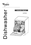
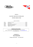
United States Patent 1161
[1 1] Patent Number:
Wing et al.
[45]
[54]
KEY PACK
[76]
Inventors:
Date of Patent:
Mar. 3, 1987
FOREIGN PATENT DOCUMENTS
Russell T- Wing; David H- Palmer,
bth
fZOOSOLk'
A
geepgaven Minan 6:5‘; ve
'
.,
482277 4/1952 Canada ........................... .. 70/456 R
..
.
Primary Examiner-William
Price
I
Assistant Examiner-Sue A. Weaver
[21] Appl' No; 728,524
[221 Filed:
4,646,913
Attorney, Agent, or Firm—Kinney & Lange
Apr. 29, 1985
[57]
ABSTRACT
A key holder is for keys with standardized heads of
_
,
about the same width as standard key blades. The key
[63]
Related U'S' Apphcatmn Data
Continuation-impart of Ser. No. 518,408, Jul. 29, 1983,
[5 1]
[52]
Int. Cl.4 .................... .. A45C 11/32; A47G 29/10
US. Cl. ................................ .. 206/372; 206/ 37.3;
[58]
Fleld of Search ...................... .. 206/ 37, 37.1-37.8,
key heads and these cap screws from Storage position
206/381 38-1; 70/408, 456 R1 457’ 460; 30/158
inside of the casing to position for use of the key outside
abandoned.
_
[56]
206/3716; 206/37-8; 70/408; 70/456 R
_
holder includes a casing which has a ?at base wall and
a plurality of parallel, spaced-apart, elongated key com
partment side walls extending integrally upwardly from
the base wall to form a plurality of parallel key com
partmonto Koys are pivotally mounted in outer end
portions of the key compartment Side walls on remov_
able cap screws and are pivotable about openings in the
of the casing. Leaf springs, one in each key compart
Refetences cued
U.S. PATENT DOCUMENTS
ment, push the keys against the side walls with sufficient
force to frictionally hold the keys in place each within
616,689 12/1898 Ruettgers ............................ .. 30/158
“5 0W“ key °°mpartm_em whethe.’ or not one ‘3.’ the
2395,123
9/1942 Mndnon __
" 70/45o R
other of the cap screws 1s temporarily removed to insert
2,371,308
3/1945
MOSCh . . . . . . . . .
. . . . . .. 206/38
Of remove other kqys- Each leaf Sprmg also exerts 811111
2,402,347 6/1946 Rotheraine _,
2,611,260 9/1952 Pontin ........ ..
2,618,958 11/1952 Gqodson -
,_ 70/456 R
.. 70/456 R
cient force against its key to frictlonally hold the key in
whatever position the key is positioned by the user. Key
711/456» R
-- 70/456 R
movement ?ngers, one in each key compartment, are
pivotally mounted about their center portions in posi
2,695,511 11/1954 Wmg e1 81-
2,696,101 12/1954 Dysart ............................ .. 70/456 R
non whore upward movement of only one end of only
3322M """"""""""""""" "
i
3:263:464 8/1966 Campbell .
__ 7o/456 R
one such ?nger will access only one key to move it from
the storage posmon to a pOSltlO?fWhCI'C 1t can be ac
3,457,746
Cessed manually and Plvoted out or “se
7/1969 Glassman
3,618,346 11/1971
4,045,984
.. 70/408 x
Humphrey ..
..... .. 70/408
9/1977 McDonald ...................... .. 70/456 R
/ /
4 Claims, 9 Drawing Figures
\
I .’_ _ _, k _ _
\
'_ d , '1
'_‘ _’ _
I
/
40
72
72
\o
/
\\/4/?1,/
///// 24
/ 4" /
4% I, (4
‘'1
34
/
f’
.
,1’ \
‘11111111 ' 111mm |
1
'l 1 1 1 I91
l. l I
/0
\
\~-—-""
e
v U.S. Patent
Mar. 3, 1987
Sheet lof2
'
Hum“
‘4,646,913
|
llll 1|
.II
38
l
~
24
/6
63
3125.5’
32
34
40
28
1
4,646,913
2
flap about in an unmanageable manner making it dif?
cult to apply the key to a lock and to rotate the key in
KEY PACK
the lock once it was inserted.
This is a continuation-in-part of application, Ser. No.
518,408, ?led July 29, 1983, now abandoned.
SUMMARY OF THE INVENTION
BACKGROUND OF THE INVENTION
A key pack or key holder for storing, selecting and
using ?at, relatively thin and wide, elongated articles
1. Field of the Invention
such as keys having blade ends and having head ends
This invention relates to key packs or key holders for
storing a plurality of keys or other flat, relatively thin
that are not appreciably wider than the blade ends. Such
a key holder includes a casing having a base wall and a
and wide, elongated articles; such holders including
plurality of parallel, rigid, spaced~apart, elongated, arti
means for selectively accessing one particular key from
cle compartment side walls, each side wall being inte
the plurality of keys.
gral with the base wall and extending outwardly there
2. Description of the Prior Art
from at right angles to it and also extending longitudi
Keys are often carried on key rinlgs, and people such 15 nally in direction from the base wall parallel to the
as watchmen often attach these rings by chains to their
general plane of the base wall. In the form of the inven
belts or some other portion of their clothing, while
tion as shown, at least one casing slotted end wall is
others with perhaps less keys per ring carry them in
provided and includes outer end portions of the side
walls and a solid end bar joining and integral with each
their pockets or purses. The abrasive action of such
keys on rings is similar to that of the constantly rotating 20 of these side wall outer end portions. The invention can
hammermill, and pocket and purse linings are rapidly
be made to operate satisfactorily without the solid end
worn out when the person carrying the keys is at all
bar.
active.
Means is provided for pivotally mounting the keys or
Keys are also often carried in leather or plastic key
other articles adjacent the casing slotted end wall
cases with a considerable number of keys each fastened 25 through the instrumentality of a key head opening in
to its own resilient hasp, and with the resilient hasps
each key or other article adjacent a head end thereof.
pivotally mounted with respect to a ?at rectangular key
The keys, when so mounted, are movable between a
hasp holding plate which is permanently mounted at
storage position wherein the keys are entirely within the
casing to a position for use extending outwardly from
one end of the key case. Such key cases usually include
two front flaps which can be snapped or a side flap
the casing.
which can be zipped to encompass the keys within the
A plurality of article movement ?ngers are mounted,
one between each adjacent pair of casing article com
partment side walls, and each ?nger is of a size and
case.
These methods of carrying keys and other methods
suffer from the dif?culty that it is hard to distinguish
and to separate one key from the other without making
con?guration to have a ?rst ?nger edge portion thereof
shape and, sometimes, by the position of the key in the
lying in adjacent relation to at least one key or other
article when the key is in its storage position, each ?n
ger being mounted for pivotal movement with respect
to the casing between a normal ?nger rest position and
case or on the ring. If somewhere between 6 and 12 keys
a ?nger operative position in contacting interfering
‘ a visual inspection and then without having to visually
recognize a particular key for a particular look by the
are to be carried by a single user, and/or if two or more 40 relation to its adjacent key to cause it to move from its
of the keys are designed to go into the same brand of
storage position toward its position for use. Each such
lock, it is virtually impossible to identify quickly each of
?nger is provided with at least one operating extension
or button which extends outwardly from edges of the
the keys from all of the others, time after time after time.
On Nov. 13, 1954, Russell T. Wing, one of the co
key compartment side walls, and each operating button
inventors of the present key pack, together with Dodge
45 is of size and con?guration such that manual movement
E. Wing, were awarded US. Pat. No. 2,695,511 for a
of the button in direction toward the side wall causes
KEY HOLDER in which keys were pivotally mounted
in a casing for moving between a stored position inside
the casing and an access position outside of the casing.
The keys were accessed by swinging a pivotally
mounted selector plate to the right or to the left until it
the article movement ?nger to push its key from its
storage position toward its position for use.
A plurality of article position retaining means are
was aligned with the desired key and then, by pressing
on a ?nger grip causing an ejector to push against the
key from one side to cause it to swing up to an access
position on the other side of the key holder. A plurality
of ?exible separators were utilized to be de?ected to
allow individual keys to be placed between adjacent
separators, and semi~spherical elements secured to the
separators were used to pass through openings in the
heads of the keys to pivotally support the keys in the 60
key holder. This structure proved workable, but since
the keys were not positively locked or held ?rmly in
position, the keys tended to become dislodged while
situated one between each pair of article compartment
side walls. In the form of the invention as shown, such
means takes the form of a plurality of leaf springs. Each
leaf spring is positioned to bear against a key or other
article to force that key or article against one of such
side walls whether the key blade is between the com
partment side walls or not. The force of the leaf spring
on the key and consequently the force of the key on its
opposite compartment side wall causes enough friction
to sustain the key in whatever position it is placed by the
user.
In our parent application, a number of patents were
cited which now become part of the prior art statement.
A special search for the details of this invention has
other keys were being added or removed. Also, the
not been made, but applicants and those in privity with
structure of the Wing et al patent provided no way to 65 them are aware of no prior art which is closer than that
positively identify keys in situations where the identi?
discussed above or cited in the parent application and
cation had to be made in the dark. Further, once the
are aware of no prior art which anticipates the claims
proper key was selected and ejected, the key was free to
herein.
3
4,646,913
BRIEF DESCRIPTION OF THE DRAWINGS
FIG. 1 is a side elevational view of a key pack or
holder made accordng to a ?rst form of the invention,
showing a key in condition for use and showing in dot
ciably more than 5".
The solid end bar 28 helps to insure that the key
compartment side walls 24 do not deform in direction
toward each other due to the lateral stresses placed
thereon. However, when the material and the thickness
of the side walls is properly selected and designed, a key
holder 10 of the invention can operate satisfactorily
without either solid end bar. These end bars, positioned
ted lines that key being moved from a storage position
toward a position for use;
FIG. 2 is an enlarged plan view of the key holder of
FIG. 1 with a base wall of a key holder casing upper
as seen in the drawings, also serve to protect accidental
access to the outer and inner operating extensions or
most;
FIG. 3 is a side elevational view of the key holder as
seen in FIG. 1 to the scale of FIG. 2;
buttons 62 and 63, respectively; and serve to protect the
material of a pocket or purse in which the device is
FIG. 4 is a plan view of the key holder of the inven
tion with the base wall of the key holder casing under
15
neath;
FIG. 5 is a sectional view taken on the line 5-—5 in
FIG. 4 showing a key at the right end of the key holder
being moved from storage position toward position for
use;
FIG. 6 is a vertical sectional view also taken on the
line 5—5 in FIG. 4, but showing a key to the left in
FIGS. 5 and 6 being moved from its storage position
toward its position for use;
FIG. 7 is an enlarged sectional view taken on the line
4
the walls 24 is held to not less than %” and not to appre
stored from being abraded by such buttons.
While the key holder 10 of the invention is shown
herein as being double-ended, that is as having a plural
ity of keys fastened adjacent each slotted end wall 26, it
is to be understood that by having the plurality of paral
lel, spaced-apart, elongated key compartment side walls
such as 24 extend only in one direction, for example, to
the left in FIGS. 3, 5 and 6, a much more compact key
holder will result and will be useful for persons having
only a lesser number of keys to be carried and used.
In the main form of the invention as shown herein,
25 adjacent side walls 24 de?ne a plurality of parallel key
'
compartments 32. In this form of the invention, each
FIG. 8 is a plan view of a key forming template
key compartment can carry two keys or other relatively
which can be nominally carried in the key holder of the
thin and wide, elongated articles.
‘
invention and temporarily removed to trim the head of
As best seen in FIGS. 2 and 4, outermost key com
a key preparatory to mounting the key in the key 30 partment side walls 24 are of substantially greater thick
' holder, the key template being shown in overlying rela
ness than the inner key compartment side walls, and
tion to a key to be trimmed; and
these outer walls are also designated 34,34. As perhaps
7—7 in FIG. 3;
FIG. 9 is a sectional view taken on the line 9-9 in
FIG. 8.
DETAILED DESCRIPTION OF THE
PREFERRED EMBODIMENTS
A key pack or holder 10 is for storing, selecting and
1 using keys or other relatively thin and wide, elongated
‘ articles which can be pivotably mounted therein on an
axes transverse to plane at their widest dimension. The
best seen in FIGS. 2 and 4, one outer end portion 36 of
each of these outer key compartment side wall is cut
35 away to provide a clearance for a knurled head 38 of
one of the cap screws 14. The cap screw 14 is also
provided with a shank 40 having a threaded outer end
portion 42. Cap screw receiving openings 44 are pro
vided through each of the slotted end walls 26, and the
cap screw receiving opening 44 through each outer key
casing, and a plurality of key position retaining, friction
providing, leaf springs 18 mounted inside of the casing
compartment side wall 34 at the end which has not been
cut away is provided with threads to receive the
threaded outer end portion 42 of each cap screw shank
40.
When the key holder of the invention is ?rst sold, and
before there are any keys assembled thereon, a leaf
12 on the cap screws 14.
spring 18 is found situated in each key compartment 32.
' holder includes a casing 12, a pair of knurled cap screws
14,14 for mounting keys or similar articles in the casing,
a plurality of key movement ?ngers 16 mounted in the
The key casing 12 includes a ?at base wall 22, a plu
rality of mutually parallel, rigid, spaced-apart, elon
Each leaf spring is provided with a pair of cap screw
receiving openings 46 therein, and is fastened in place
gated key compartment side walls 24, each integral with
by the cap screws 14,14. As best seen in FIG. 4, the leaf
the base wall and extending outwardly from it in normal
springs, viewed on edge, tend to take a very ?at, but
relation to it and also extending in longitudinal direction
generally U-shape form. Each spring includes a rela
away from the base wall in both directions in generally
tively ?at center portion 48, upwardly flaring end por
parallel relation to the general plane of the base wall. In
tions 50,50 and downwardly ?aring outer ends 52,52
the form of the invention as shown, the casing 12 also 55 extending integrally outwardly from the end portions
includes a pair of slotted end walls 26,26, each consist
50,50.
ing of a solid end bar 28 and outer end portions 30 of the
Seen in plan, each relatively ?at center portion 48 of
side walls 24 which are integral with the end bar 28.
each leaf spring 18, as best seen in FIGS. 5 and 6, extend
As can perhaps best be seen from FIGS. 5 and 6, the
upwardly from its middle toward the outer end portions
diameter of these semi-circular outer end portions 30 of
50,50. The middle of each ?at center portion 48 includes
each of theside walls 24 is only slightly larger than the
a key movement ?nger holddown tab 54 extending
diameter of the truncated head portions 74 of each of
integrally from the center portion 48 generally at right
the keys 72 installed in the key holder 10. As is common
angles to the ?at plane of the body of the leaf spring 18.
knowledge, the width of the blade end portions of keys
The base wall 22 of casing 12 is provided with a
in common usage today is in the neighborhood of 5/16"
transversely extending key movement ?nger retaining
to 4;". Accordingly, it has been found that an excellent
slot 56. Each key movement ?nger 16 includes at the
embodiment of this invention can be constructed if the
diameter of the semi-circular outer end portions 30 of
center thereof a retaining boss 58 of dimension to ?t
inside of and to be retained by the retaining slot 56. See
5
4,646,913
FIGS. 5 and 6. A ?rst edge portion of each of the key
movement ?ngers 16 is provided with a ?rst ?nger edge
portion lying in adjacent relation to a key when the key
is in its storage position. Each key movement ?nger also
is provided with a pair of reduced area necks 60,60, for
the purpose of allowing outer end portions of each key
After each key 72 has been prepared, in order to load
them into key holder 10, those keys to be associated
with key numbers 1 through 6 are installed by removing
the cap screw 14 to the left as seen in FIGS. 1, 2, 4, 5
movement ?nger 16 to ?ex with respect to the center
and 6. Truncated head portion 74 of key to be numbered
1, for example, is slid between the leaf spring 18 and its
spaced-apart key compartment side wall 24 in adjacent
relation to the center portion 48 of the leaf spring, and
portion thereof.
In the form of the invention as shown, a second ?nger
edge portion of each of the key movement ?ngers 16 is
provided with an outer operating extension or button
62, and an inner operating extension or button 63. These
?ngers 16 are assembled in the casing 12 so that each
outer operating extension or button is situated in a key
compartment 32 adjacent the inner operating extension
or button 63 of its adjacent key movement ?nger(s).
6
pushing on an outer operating extension or button 62 or
an inner button 63.
slid to the left as seen in FIG. 4 to position the key head
opening 80 thereof in alignment with the cap screw
receiving openings 44 and 46 of the slotted end wall 26
5
and leaf spring v18, respectively. The friction furnished
by the leaf spring 18 between its adjacent key compart
ment side walls 24 will keep the key from being uninten
The various parts or elements of key holder 10 can be
tionally displaced, and will so maintain the key 72 and
made out of a number of different kinds of materials; but
speci?cally its truncated head portion 74 in position so
in one form, the casing 12 can be made of a ?rm and
that the key head opening 80 and the cap screw receiv
unyielding plastic, the cap screws 14 and the leaf 20 ing openings 44 and 46 remain in alignment even as keys
springs 18 can be made of metal, and the key movement
2 through 6 are similarly positioned in their key com
?ngers 16 can be made of a slightly resilient plastic.
partments. When all of the keys to be installed on that
When the key holder 10 of the invention is ?rst pur
side of the key holder are in position, the cap screw 14
chased for the ultimate user, it will not, of course, have
will be repositioned through all of the openings 44, 46,
on it the personal keys of the user. However, it can be 25 and 80 and the cap screw will be turned down to fasten
provided with a key template 66 having a head end and
the threaded outer end portion 42 of its shank 40 in the
a blade end such as is shown in plan in FIG. 8. This
uncut key compartment side wall 34.
template 66 can have a cap screw receiving opening 68
Keys or other similar ?at articles such as the key
through its head end so that it can be positioned in one
template 66 can be installed in the opposite end key
of the key compartments 32 such, for example, as the
compartments designated 7 through 12 in a similar man
right-hand end of the top compartment as seen in FIG.
ner.
4. As seen in FIG. 9, template 66 is provided with a
The tension of the key position retaining, friction
short key positioning boss 70 which is not suf?ciently
providing, leaf springs 18 is such that whenever one or
long enough to prevent the template from taking its
the other of the cap screws 14 is partially or entirely
position in its key compartment 32 when being stored. 35 removed in order to insert or replace a key, the leaf
springs will hold themselves and the other keys aligned
with the cap screw receiving openings 44 and the key
head openings 80 in ?xed position within the casing 12
The key pack or key holder 10 of the present inven
tion is designed to be used with special keys having
truncated heads and not with ordinary keys which must
have sufficiently wide heads to provide the user with a
until such time as the desired change is made and the
suf?cient grip to turn the key in a hard-to-operate lock. 40 cap screw is once again replaced.
With a key held in an operative position in a key holder
At least as important, each leaf spring 18 will exert
of the invention and then inserted into a lock, rotating
suf?cient pressure on the key or keys in its key compart
of the key holder itself provides several times as much
ment to provide all the friction needed to hold each key
in any position around its cap screw into which the user
leverage or mechanical advantage as can be obtained
using a hand held ordinary key.
45
has placed it. This makes it possible to position a key in
It is to be expected that as the present key holder 10
alignment with the longitudinal axis of the casing and,
initially ?nds its place in the market, special keys 72
with truncated head portions 74 will not be readily
holding only the casing, line the key up with a lock and
insert it therein. The casing can then be rotated 90° with
available. This is the reason that key template 66 can be
mounted in or furnished with the key holder 10. Then
when the purchaser obtains key holder 10 from a key
respect to the key in the lock and it will then be in a
position to exert all the force needed- to positively turn
the key in the lock.
maker, the key maker can take each of the purchaser’s
ordinary keys 76 with full head portions 78 and ma
But ?rst, in order to select and eject a particular key,
for example, the key designated as key situated to the
chine, grind, or ?le them down to size such as is shown
left in the ?rst key slot as seen in FIGS. 5 and 6, the left
in FIGS. 5 and 6, for example.
55 end of the key movement ?nger 16 aligned with that
In order to do this, the key maker will lay an ordinary
key must be raised in upward direction as seen in FIGS.
key 76 on top of key template 66 with positioning boss
5 and 6 to contact the key and push it from its storage
70 extending into a key head opening 80 and then fasten
position part way out of the key case to the access posi
the assembled template 66 and ordinary key 76 in a vice
tion shown in dotted lines in FIG. 1 where it can be
where he can use a grinder or a ?le to remove those 60 manually pivoted to position for use as seen, for exam
portions of the keyhead 78 which extend outside of the
ple, in full lines in that ?gure. To accomplish this, the
template, thus to fashion a key such as key 72 usable in
the key holder 10.
Each key compartment 32 can be assigned a number
outer operating extension or button 62 of that key
movement ?nger 16 will be identi?ed by sight (where
light is available) or by touch and position and counting
as an aid to identi?cation of the key therein and, as seen 65 (where the key must be accessed in the dark). Once
in FIG. 2, this number can be inscribed on the outer
located, the extension button 62 will be moved from the
surface of the base wall 22 in such a manner as to indi
position as seen in FIG. 5 on the left-hand side to the
cate whether the numbered key can be accessed by
position as seen in FIG. 6 by using one of the ?ngers of
4,646,913
7
contact that particular key 72 to lift it from the position
as seen in FIG. 5 to the position as seen in dotted lines
in FIG. 1 and in full lines in FIG. 6. The key can then
be moved to position for use.
To access key such as key 12, the inner operating
extension or button 63 at the opposite end of the same
key movement ?nger 16 will be deflected in direction
from a storage position in a key compartment
within the casing to a position for use extending
toward the casing, (see FIG. 2) thus causing that partic
ular end of the key movement ?nger 16 to move from its 10
rest position as seen in FIG. 6 to its operative position as
seen in FIG. 5. In FIG. 6, the right-hand key 72 has
been removed for clarity of illustration; but in FIG. 5 it
is shown in its accessed position, having been forced
there by the upward movement of the right outer end 5
portion of the key movement ?nger 16. When once so
accessed, it, too, can be pivoted over to a convenient
position for use.
8
and extending in longitudinal direction from the
base wall parallel to the general plane of the base
wall, each pair of adjacent side walls partially
de?ning a key compartment;
B. means for pivotally mounting a plurality of keys
adjacent longitudinally extending outer end por
tions of the side walls for movement of the keys
one hand. This will de?ect ?nger 16 and cause it 'to
-
In each case, once the key has been used for its in
tended purpose, it can be swung manually back into its
stored position completely within the casing 12. The
tension provided by the leaf springs 18 will, in every
outwardly of the casing;
C. a plurality of key movement ?ngers, one mounted
in each key compartment, each ?nger being of size
and con?guration to have a ?rst ?nger edge por
tion lying in adjacent relation to at least one key
when such key is in its storage position, each ?nger
being mounted for limited movement with respect
to the base wall between a normal ?nger rest posi
tion adjacent to said one key and a ?nger operative
position in contacting relation to such key to cause
the key to move from its storage position toward its
position for use, and each ?nger being provided
with at least one operating extension extending
from a second ?nger edge portion on an opposite
case, cause each key to remain in its position of rest,
either partly accessed, in position for use, or in its stor
age position wherever it ends up or is released from 25
action by the ?ngers of the user or by movement of the
edge of the ?nger from the ?rst edge portion, said
?nger operating extensions each nominally extend
ing outwardly from edges of the key compartment
?exible key movement ?nger 16.
side walls which are adjacent said base wall, and
Modi?cation can be made in the double-ended form
" of the invention as shown in the drawings without de
each operating extension being of size and con?gu
parting from the spirit of the invention. For example, in
extension in direction toward said key compart
ration such that manual movement of any such
order to provide an easy identi?cation of the end of the
ment side walls will cause its key movement ?nger
key holder holding keys identi?ed by key compart
to contact and to move a key in its compartment
ments 1 through 6 as opposed to the end of the holder
from said storage position toward said position for
identifying compartments 7 through 12, the slotted end
use;
wall 26 and particularly its solid end bar 28 can be omit 35
ted at one end of the key holder, thus leaving the key
compartment side walls 24 including their outer end
portions 30 to provide the cap screw receiving openings
44, the end portions 30 being rounded off to roughly
:
D. each operating extension of each key movement
?nger being so spaced from the other extensions
that manual movement of one extension in direc
tion toward the side walls will not cause any other
extension to move in such direction;
E. wherein said means for mounting said keys in
conform to the head end of the keys to be mounted
-‘ thereon. Then the key operator, if operating in the dark,
can simply feel for the one remaining solid end bar 28
and thus identify the end of the holder having compart
ments 1 through 6; knowing that the end of the holder
not having the solid bar 28 identi?es the end of the 45
cludes said key head opening in each key, mount
ing pin receiving openings through outer end por
tions of said casing key compartment side walls,
and a mounting pin adapted to be removably in
stalled in said key head openings and said pin re
ceiving openings;
holder associated with compartments 7 through 12.
F. wherein a plurality of key position retaining and
As seen in FIGS. 2 and 3, recessed panels 82 and 83
can be provided for displaying instructions, return ad
friction providing leaf springs are situated one in
dress of a user, an advertising message, or any other
each key compartment, each leaf spring having a
retaining pin opening provided through at least one
end thereof, each said leaf spring being of con?gu
desired intelligence.
50
Although the present invention has been described
with reference to preferred embodiments, workers
skilled in the art will recognize that changes may be
made in form and detail without departing from the
spirit and scope of the invention.
What is claimed is:
1. An apparatus for storing, selecting and using a
plurality of ?at, relatively thin and wide keys, said keys
55
compartment;
having a blade end and a head end, and said keys each
being provided with a key head opening adjacent its
head end; said apparatus including:
60
A. a casing having
(1) a base wall, and
‘
(2) a plurality of ?xed, parallel, rigid, spaced-apart
elongated key compartment side walls, each side
wall being integral with the base wall and ex
tending outwardly from it in normal relation to it
ration to press against the surface of a ?rst side wall
de?ning its key compartment and to press a key
mounted in said compartment against the surface of
a second side wall de?ning the opposite side of the
65
G. wherein the key compartment side walls extend
from the base wall in two opposite longitudinal
directions in parallel relation to the general plane
of the base wall;
H. wherein there is provided means for pivotally
mounting a plurality of said keys adjacent to each
set of longitudinally extending end portions of the
side walls for movement between storage positions
and positions for use;
I. wherein each leaf spring is provided with a pin
retaining opening at each end thereof and is
adapted to be positioned in its key compartment by
4,646,913
removably installed mounting pins- extending
through said leaf spring pin receiving openings in
tion for use extending outwardly from the casing;
each end thereof;
C. a plurality of article movement ?ngers, one
1. wherein said base wall is provided with a trans
mounted between each adjacent pair of casing
article compartment side walls, each ?nger being
versely extending key movement ?nger retaining
slot at a side thereof adjacent the key movement
of size and con?guration to have a ?rst ?nger edge
portion lying in adjacent relation to at least one
article when such article is in its storage position,
?ngers;
K. wherein each key movement ?nger is provided
with a key movement ?nger retaining boss extend
ing centrally downwardly therefrom in position to
?t into said base wall retaining slot; and
10
an article compartment within the casing to a posi
each ?nger being mounted for limited pivotal
O
movement with respect to the base wall between a
normal ?nger rest position adjacent to said one
L. wherein each leaf spring is provided with a cen
article and a ?nger opertive position in contacting
trally positioned key movement ?nger holddown
tab extending outwardly from a central portion of
the leaf spring in position to contact the key move 15
ment ?nger and to hold it down with its retaining
boss situated in the base wall retaining slot.
2. The apparatus of claim 1 wherein:
M. each leaf spring is generally U-shape in edge view,
and extends from a relatively flat center portion in 20
contact with and pressing against a ?rst side wall of
the key compartment to a pair of upwardly ?aring
outer end portions, each outer end portion contact
ing a second opposite side wall when no key in
stalled and contacting an installed key to press it 25
against the second side wall, said outer end portion
contacts being made in the general vicinity of the
leaf spring key receiving opening.
3. The apparatus of claim 1 wherein:
N. each leaf spring includes a relatively short down 3 O
relation to such article to cause the article to move
from its storage position toward its position for use,
and each ?nger being provided with at least one
operating extension extending from a second ?nger
edge portion on an opposite edge of the ?nger from
the ?rst ?nger edge portion, said ?nger operating
extensions each nominally extending outwardly
from edges of said article compartment side walls
which are adjacent said base wall, and each operat
ing extension being of size and con?guration such
that manual movement of any such extension in
direction toward such side walls will cause its arti
cle movement ?nger to contact and to move an
article in its compartment from said storage posi
tion toward said position for use;
D. wherein said ?at, relatively thin and wide elon
gated articles are constituted as:
extending outwardly from the upwardly ?aring
(l) a plurality of keys each having a blade end and
a head end, each key being provided with a key
end portions.
4. An apparatus for storing, selecting and using ?at,
relatively thin and wide elongated articles adapted for
(2) at least one key template having a head end and
a blade end, the blade end being provided with a
wardly flaring outer end portion integral with and
head opening adjacent its head end, and
cap screw receiving hole at an outer end portion
pivotal mounting at one end thereof to move in the
plane of the thin dimension; said apparatus including:
A. a casing having
(1) a base wall, and
(2) a plurality of ?xed, rigid, parallel, spaced-apart,
elongated, article compartment side walls, each
40
of the blade end and a key positioning boss and
extending outwardly from one face of its head
end; and
E. wherein the pro?le of the head end of the key
template being such that when the key template is
side wall being integral with the base wall and
extending outwardly from it in normal relation
to it and extending in longitudinal direction from
the base wall parallel to the general plane of the 45
base wall, each pair of adjacent side walls par
tially de?ning an article compartment;
B. means for pivotally mounting at least one of said
articles adjacent a longitudinally extending outer
end portion of at least two of the side walls for
movement of the article from a storage position in
removed from the apparatus for storing articles and
situated against a key with the template key posi
tioning boss inserted in a key head opening of the
key, with the blades of the key template and key in
overlying parallel relationship to each other, then
the removal of all portions of the key head outside
of the template head will shape the key so that it
will lie entirely within the casing after it has been
installed in the apparatus for storing articles.
1‘
55
65
It
*
I‘
it


![10780-90006 - 10780A Laser Receiver for 5501A [Prefix 1948] (Mar](http://vs1.manualzilla.com/store/data/006009643_1-6e2f54ebb2199ef6df634558ba4c1bb6-150x150.png)