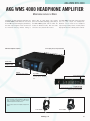
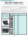
1
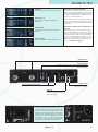
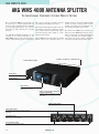
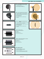
AKG WMS SR 4000
AKG WMS 4000 RECEIVER
THE CUTTING-EDGE TRUE DIVERSITY RECEIVER
The SR 4000 True Diversity Receiver offers
maximum convenience with state-of-the-art
technology and the widest range of functions
in its class.
Naturally, the SR 4000 is optimally equipped for the setup of large multichannel
systems, so that connecting antenna splitters, power supply units, computer networks,
etc. is quite easy.
The accurate battery life readout is a novel
and invaluable feature for live sound applications. The transmitter uses a pilot tone to
transmit accurate information such as bat-
Of course the SR 4000 operates in an extremely wide UHF band (30 MHz) with preprogrammed frequency presets, each providing
up to 18 intermodulation-free subchannels*.
The maximum number of selectable frequencies is 1200. The large backlit color display
The integrated software does not only permit and the setup control make the unit easy to
automatic setup and frequency scanning but use, and a programmable LED ring indicates
also remote control and monitoring from a PC selectable critical conditions.
via a dedicated interface. With the optional
MCS 4000 Mission Control Software, setting Housed in a half-rack 19” all-metal case, the
up and monitoring highly complex systems is SR 4000 is the most compact, reliable, and
child’s play. A logic output allows control of powerful UHF receiver in its class.
external devices, e.g., automatic microphone
mixers.
tery status to the receiver that displays the
remaining battery life in hours. The pilot tone
decoder also evaluates and displays other
important data including the status of the
MUTE switch on the transmitter.
Backlit display
High-contrast color display using “Black Mask” technology
indicates all system parameters in plain text.
Half-rack 19” all-metal case
Standard accessories include a rugged rack-mounting kit.
SR 4000 Receiver
Jog switch
For simple programming of the receiver
Programmable status display
Displays for LowBatt, Audio Level, RF Level and
Diversity at a glance
Display details
JOG SWITCH
Multifunctional control element for system programming,
no tool needed, can be operated single-handed.
➊
➐
➎ Rehearsal Mode: Quick check of RF and AF signal
quality
➊ 8-segment Audio Bargraph Display
➋ Frequency Setup Menu, 3 modes: Auto, Preset,
Frequency
➏ Special functions: Receiver name, status display,
threshold level, system info, …
➌ Scanning function: AutoScan detects RF signal in
the entire bandwidth
➍ Setup for SQL, Level, or TCSQ
➐ 8-segment RF Bargraph Display incl. diversity
➋
➌
➍
➎
➏
* The maximum number of selectable channels may vary in accordance with local frequency plans.
44
Display details
www.akg.com
AKG WMS SR 4000
Auto Setup
Automatic frequency setting and finding of free channels.
Environment Scan
Analyzes the RF environment for interference-free
transmission.
Rehearsal Mode
Setup Assistant for the optimal setting of the system
parameters.
Battery life display
Display of transmitter’s remaining battery life in hours.
Environment Scan and Rehearsal Mode
The SR 4000 comes with a large number of assistants that
make a professional setup incredibly easy and substantially
increase operating reliability. The Environment Scan “spies
on” the RF environment and warns of interfering frequencies
in time (e.g., active TV transmitters etc.).
Rehearsal Mode also features an early warning system that
records the most important system parameters during the
soundcheck and can be used to identify potential problems
ahead of time.
Multichannel capability, frequency management, and
auto setup
Its wide frequency range and multiplicity of selectable frequencies make the WMS 4000 an excellent choice for multichannel systems. The built-in frequency management
system helps you find the right frequency. Preset banks provide sets of intermodulation-free frequencies. The Auto
Setup function rapidly identifies clean frequencies. For a
FREE download of the frequency management program for
your PC, visit www.akg.com/frequencies.
BNC Antenna port
For connecting simple or complex antenna networks.
Lockable DC input
For a secure connection to local or central power supply components,
such as the PSU 4000.
Network output
For remote control from a PC using
MCS 4000 control software.
Professional XLR and jack outputs
With output level selector.
LOGIC OUT
For the control of external devices such
as automatic microphone mixers and
media control systems.
Logic Out and Output Level Selector
The Logic Out supplies the following information: first, a signal indicating the mute status of the audio output, and
second, the condition of the transmitter batteries. A unit
with Logic In can be programmed to have a signal light illuminating when the transmitter battery is low. The output
level selector can be used for setting the audio signal either
to standard level or to +6 or -30 dB. This function allows
you, for example, to adjust the level of a wireless condenser
microphone to that of a hardwire dynamic microphone.
www.akg.com
45
AKG WMS CU 4000
AKG WMS 4000 CHARGING SYSTEM
THE INTELLIGENT WAY TO POWER WMS 4000 TRANSMITTERS
The CU 4000 Charging Unit revolutionizes battery management for wireless systems. The
heart of the charging system is the BP 4000
Battery Pack with built-in active monitoring. An
integrated microprocessor continuously monitors battery status and accurately calculates
the remaining battery life. In conjunction with
a WMS 4000 wireless transmitter, these data
are not only indicated on the transmitter display but are also transmitted to the receiver via
pilot tone. The transmitter’s remaining battery
life can thus be read out on the receiver within
a few minutes’ accuracy, putting an end to the
nightmare of batteries failing in the middle of
a performance.
A processor-controlled pulse charging system
charges the battery pack quickly yet gently,
while the integrated “Charge Balance
Management” feature makes sure that only as
much energy is fed to the battery pack as had
previously been drawn from it. In addition, several monitoring circuits and a temperature sensor prevent the battery pack from being overcharged.
A self-discharge counter does not only measure
battery discharge during operation but also
determines the amount of discharge after prolonged storage periods. As charging begins, the
BP 4000 circuitry communicates with the
CU 4000 Charging unit
Charging status display (LED)
Recovery key and LED
Starts a battery recovery cycle. SBMS detects the
battery status and suggests starting a recovery
cycle to prolong battery life.
2 universal charging compartments
Each compoartment accepts an HT 4000,
PT 4000, or BP 4000 battery pack.
BATTERY CARE
Rechargeable batteries are known to suffer from the so-called
“memory effect”. The capacity of a rechargeable battery will
decrease over time if it is not fully discharged. If a battery is
discharged only to 50% of its capacity over many charging cycles,
it will finally "believe" its capacity to be only 50%, so that it cannot be charged fully any more. To eliminate memory effect, we
recommend completely discharging and recharging the battery
pack periodically (recovery cycle). SBMS permanently monitors
battery parameters and detects the need for a recovery cycle.
46
The Recover LED illuminates to indicate it is time for servicing the
battery pack. Since a recovery cycle may take 14 hours, the best
time to run it is during the night. In any case you will need to start
the recovery cycle manually. If you service your battery pack regularly it will retain its maximum capacity throughout its useful life.
www.akg.com
CU 4000 charging unit in order to “tailor” the
charging process optimally to the status of the
battery pack. To eliminate memory effect, the
CU 4000 automatically checks whether the batteries need a recovery cycle, and automatically
starts the cycle upon confirmation by the user.
The charging unit provides two charging compartments that allow you to charge two transmitters (HT 4000, PT 4000) or two battery packs at
the same time. Charging time apr. 1 hour.
The combined BP 4000 plus CU 4000 system
is an investment that will quickly help cut
expenses and reduce environmental hazards
from used batteries.
Lockable DC jack
For connecting a local or central power supply unit
such as a PSU 4000.
MOBILE CHARGING UNITS
AKG WMS CU 4000
CU 4000 – Charging unit in a flight case
Several charging units can be fitted into a rugged flight case as a compact solution for large
systems. (Costume Mode)
BP 4000 Intelligent quick-replacement battery pack
Internal RAM
Records charging/discharging processes and provides
a database for optimizing charging parameters
(Charge Balance Management).
Charging unit – Features:
Data interface to transmitter electronics
Sends battery status information to the
transmitter for accurate capacity readout.
• Smart battery management
– overcharging protection
• 2-slot power management
• 1 hour quick charge
• Recovery Mode for complete recovery
of old or damaged batteries
• Integrated “database” for optimum
charging management
• Integrated temperature sensor
• Self-discharge counter
Integrated temperature sensor
Protects the battery pack against
overcharging and damage.
Smart Battery Management System (SBMS)
An environmentally friendly money saver, the SBMS Smart
Battery Management System is the heart of a completely
new charging technology. It monitors battery status and
controls the charging process. The battery status is read
out in remaining hours of battery life on the transmitter and
receiver displays, so you can recharge the battery pack in
time. The SBMS includes a number of intelligent monitoring
functions.
• Integrated RAM
“Inflection Point and Peak Voltage Detect” stops the charging in time, while an integrated temperature sensor in the
battery pack protects it from overheating. The Charge
Balance Management feature makes sure that only as
much energy is fed to the battery pack as had previously
been drawn from it. A self-discharge counter ensures correct charging after the battery pack has been stored for a
long time. The battery pack uses an integrated database
and charger interface to set its own charging current.
www.akg.com
47
AKG WMS PS 4000
AKG WMS 4000 ANTENNA SPLITTER
THE INDESPENSABLE COMPONENT FOR LARGE WIRELESS SYSTEMS
One or several PS 4000 antenna splitters can
be used to set up complex systems with long
antenna cables, distributed antenna networks
for room sharing applications, or to feed the
signal from a single antenna pair to several
receivers.
The 220 MHz bandwidth guarantees the full
coverage of all channels available in the
WMS 4000 system. The processing and amplification of true diversity signals in combination
with various optionally available antennas 8 BNC sockets as well as two additional BNC
sockets for daisy chaining several antenna
ensure maximum reliability of reception.
splitters. This allows you to implement comHighly visible LED displays provide a clear sta- plex systems with 50 or more receivers.
tus indication even from a distance. A gain
selector switch allows for optimum matching to Of course the PS 4000 can be powered cenconnected antenna cable lengths to ensure trally via a PSU 4000 Power Supply Unit so
that it can also work as a remote powering unit
optimum signal quality.
for active antennas. The required voltage is
The PS 4000 antenna splitter features 2 BNC supplied via the antenna cables, eliminating
antenna inputs and 4 diversity outputs on the need for separate antenna power cables.
2 x BNC In, 8 x BNC Out, 2 x BNC Link, DC
PS 4000 Antenna splitter
On/off switch
Power Indicator
Status display
Lets you check the current antenna
network status at a glance.
Switch for matching the RF level to the
connected cable length
Calibration switch for optimizing antenna
signal levels.
8 BNC antenna outputs
For connecting up to 4 diversity receivers.
2 BNC antenna inputs
For connecting active and passive antenna network
components.
Lockable DC input
For the secure connection of local or central power supply
components, such as the PSU 4000.
2 daisy-chaining outputs
For connecting another antenna splitter.
48
www.akg.com
AKG WMS PS 4000
max. 3 PS 4000 cascadeable
Selecting antenna cables
Antenna cables are needed for feeding the signal of a remote antenna to the receiver. However, all antenna cables attenuate the antenna signal (cable attenuation). Since different types of cables have
different attenuation values, each type will perform best at a different length. While low-attenuation cables are usually thicker and
more expensive, they can be used for much longer runs. You can
compensate for long cable runs by using antenna boosters or active
antennas. In some cases, however, using the next higher (if slightly more expensive) grade of cable may do the trick, eliminating the
need to use active antenna components. The right type of cable can
be essential to the performance of your wireless system, prevent
problems, and help reduce costs.
A bank of dip switches on the boosters and the PS 4000 antenna
splitter allows you to match the RF signal level to the antenna input
depending on the frequency band, antenna type, cable type, and
cable length.
www.akg.com
49
AKG WMS 4000 ANTENNAS
AKG WMS 4000 ANTENNAS/ACCESSORIES
ANTENNAS TAILORED TO EVERY SITUATION
With its antennas and optional accessories specially “tailored” to the WMS 4000 System,
AKG offers the optimum solution to any type of
application, allowing users to implement even
the most complex antenna networks easily and
efficiently.
With its omnidirectional polar pattern, the
RA 4000 B Booster Antenna is is a good choice
for most applications. Thanks to its rugged,
water-resistant case and the integrated antenna
booster for use with long antenna cables, the
RA 4000 B is even suited for outdoor applications.
The SRA 1 directional antenna is especially
suitable for setting up long-range radio links if
short antenna cables are used. Because of the
passive operation and the 70° beam angle in
combination with good off-axis attenuation and
front-to-rear ratio, it works particularly well in
interference-prone RF environments.
The SRA 2 B is an active directional antenna
that works with long-range radio links and long
antenna distances. An optional laser positioning
pointer makes it easy to aim the antenna precisely at its target area.
The AB 4000 is a highly efficient antenna
booster for inserting into long antenna cables.
One booster can compensate for approx. 17 dB
cable attenuation, allowing cable runs to be
extended. Up to 2 antenna boosters can be
used in series for extremely long cable runs.
The ASU 4000 is a remote power adapter for
creating additional power feeds to complex
antenna networks. Thanks to its small dimensions, it is even possible to integrate the
ASU 4000 into narrow antenna cable ducts at
a later date.
Cabling example/cable lengths:
(RG 58)
(RG 58)
(RG 58)
(RG 213)
(RG 213)
(RG 213)
Selecting and placing antennas
The antenna is the “ear” of the radio system, which is why antennas must be selected and placed carefully. Antennas have polar
patterns similar to those of microphones, and depending on the
application, you may need Yagi antennas (comparable to cardioid/hypercardioid microphones), Log Periodic (like shotgun microphones), or omnidirectional antennas.
Installed sound
Live sound
50
If the transmitters will be used only within a rather small area
such as a stage, use directional antennas. Directional antennas
are generally used to overcome long distances or suppress unwanted signals from other directions, e.g., at open-air locations.
Omnidirectional antennas are ideal for near-field applications
where no external-direction interference is expected, e.g., indoor
events (most directional antennas are big and difficult to conceal)
or multipurpose halls with no preferred direction.
www.akg.com
TV studio
Theater
Worship center
AKG WMS 4000 ANTENNAS
SRA 1 – Passive wideband directional antenna
• For indoor and outdoor use, in particular for setting
up long-range radio links
• For use with short antenna cables
• Water-resistant design with BNC output
SRA 2B – Active wideband directional antenna
• For indoor and outdoor use, in particular for setting up
radio links for distances up to 300 m (1000 feet)
• Integrated high-performance antenna booster for use
with long antenna cables
• Remote powering option
• Rugged, water-resistant case with BNC output
• Status LED
RA 4000 B – Omnidirectional wideband booster
antenna
• For indoor and outdoor use, in particular for near-field
antenna setups with no preferred direction
• Integrated high-performance antenna booster for use
with long antenna cable
• Remote powering option
• Rugged, water-resistant case with BNC output
• Status LED
AB 4000 – Antenna booster
• BNC or N connector inputs/outputs
• DC input
• Status LED
• Water-resistant case
• DIP switch for adjustable gain
ASU 4000 – Remote powerd adapter for antennas
• BNC or N connector inputs/outputs
• Lockable DC input
• Status LED
• Water-resistant case
• for max. 3 active elements
ZAPD-21 Antenna combiner
• For indoor and outdoor use
• For setting up complex antenna networks
• Use as 2 in - 1 out antenna combiner for
multiple-antenna systems
• Use a 1 in - 2 out antenna splitter for daisy-chaining
several PS 4000s within large multichannel systems
www.akg.com
51
AKG WMS HUB 4000
AKG WMS 4000 NETWORK CONCENTRATOR
THE LINK BETWEEN THE WMS 4000 AND A PC NETWORK
The HUB 4000 is the intelligent hardware
interface between a WMS 4000 wireless
system and one (or several) PCs. No more
need for cumbersome cabling; the HUB 4000
concentrates the data flow of up to eight receivers and connects easily to any PC with an
Ethernet interface.
of 128 receivers – from a single PC!
The HUB 4000 meets all standards and requirements for smooth operation with PC components. Connection to the PC or PC network
is via standard CAT-5 Ethernet cables with RJ45 connectors, while the data are transmitted
via IP protocol.
Naturally, complex systems can also use several HUB 4000s – in fact, up to 16. With eight Working with WMS 4000 multichannel
receivers per hub, you can operate a maximum systems, you can optimize operating conve-
nience and reliability by simply linking the
WMS 4000 PC network components with
standard PC accessories. This allows you to
send receiver data through the HUB to a wireless LAN, and receive them on a tablet PC. In
the REHEARSAL mode, you can take the PC
on the stage and monitor important data such
as RF levels on site. This makes it incredibly
easy to set up the most complex system and
ensures maximum operating reliability.
HUB 4000 Network concentrator
On/off switch
Status LED
Display indicating the active channels
Data connection
For a reliable data transfer to the PC and addressing
the MCS 4000 “Mission Control Software”.
Example: WMS 4000/PC network
The example shown opposite demonstrates how stateof-the-art PC and audio technologies can be linked to
ensure a level of convenience unknown to date.
You can service and operate the entire WMS 4000 system
from permanently installed computers or a laptop with a
wireless connection to the network. You can also access
the AKG homepage via internet at any time, e.g., for
downloading the frequency management program for
other WMS systems, updating firmware, setting up a
remote desktop, etc. Total networking for total control!
52
www.akg.com
AKG WMS MCS 4000
AKG WMS 4000 MISSION CONTROL SOFTWARE
YOUR COMPUTER AS A WMS 4000 CONTROL CENTER
The MCS 4000 Mission Control Software
allows you to display the entire setup of a
WMS system on screen and to edit all settings simply by mouse click.
All relevant data, such as RF level, audio
level, diversity activity, battery status of the
transmitters, Mute/Off etc. are displayed in
real time on a graphic user surface, with
important warning messages being inserted
so as to catch the eye.
You can even set up the basic parameters of
a complete system from the computer: you want to mail it to off-site co-workers.
remote control software puts Environment
Scan, Auto Setup and Rehearsal Check at Linking a wireless system to the computer
only requires the integration of one or severyour fingertips.
al WMS 4000 HUB Network Concentrators
“History” recording is another special feature plus a computer (>500 MHz) with an
of MCS 4000 – i.e., storing the monitoring Ethernet port.
data of all channels in a log file to help with
the setup and the analysis of completed MCS 4000 is available for Windows, Mac OS
X, and Linux. A demo version as well as softsystem.
ware and firmware updates and drivers can
You can also take a snapshot of the current be downloaded from www.akg.com.
status any time, which is especially helpful if
“Get a Cup” Setup Mode
Finding and setting the right frequencies for a multichannel
setup is a difficult and time-consuming job. The WMS 4000
provides several functions including Auto Setup and
Environment Scan to speed up the process. The MCS 4000 is
an incredibly convenient software tool. It scans the system's
RF environment and uses an integrated frequency management database to calculate optimum frequencies. It automatically programs these frequencies into the receivers via
the HUB 4000 to complete the setup while you have a cup of
coffee.
“Moving PC” Rehearsal Mode
When working with WMS 4000 multichannel systems, you
can optimize operating convenience and reliability by simply
linking the WMS 4000 PC network components with standard
PC accessories. This allows you to send receiver data through
the HUB to a wireless LAN, and receive them on a tablet PC.
In the REHEARSAL mode, you can take the PC on the stage
and monitor important data such as RF levels on site. This
makes it incredibly easy to set up the most complex system
and ensures maximum operating reliability.
www.akg.com
53
AKG WMS PSU 4000
AKG WMS 4000 POWER SUPPLY
RELIABLE POWER SUPPLY FOR THE COMPLETE WMS 4000 SYSTEM
The PSU 4000 is a central power supply unit
for all components of the WMS 4000
system. A stable, interference-free voltage
(12 V/2 A or 12 V/2.5 A respectively) at three
outputs ensures a stable network. Valuable
power strip outlets are thus kept free, and
PSU 4000 Central power supply unit
hum from poorly grounded power cables can clearly visible display indicates the current
power supply status. The low-noise fan enbe minimized.
sures optimum cooling of the power supply
The PSU 4000 is an essential tool especial- unit, even at high ambient temperatures and
ly for mobile racks, since it saves a lot of under full load.
time during installation and takedown. The
1 x AC Input, 2 x DC out 12 V, 2 A, 1 x DC out 12 V, 2,5 A
On/off switch
Power indicator
Status display
100 – 240 V AC input
3 x DC outputs
DC Out 3
DC Out 2
DC Out 1
Tailor-made DC outputs
If each of the three DC outputs is connected to a PS 4000
antenna splitter, the antenna splitter to which the
antennas are ultimately connected must be connected to
DC OUT 1. This is because due to cable attenuation, the
antenna system will draw 2.5 A, which is only available
from DC OUT 1 (outputs #2 and #3 supply 2 A each).
54
www.akg.com
AKG WMS HPA 4000
AKG WMS 4000 HEADPHONE AMPLIFIER
MONITORING WITHOUT A MIXER
Integrating an HPA headphone amplifier into
the WMS 4000 system makes life a lot easier
for the FOH engineer. During the performance,
the audio output signals of each receiver can
be monitored directly, without having to
bother with an extra mixer. This feature
proves an invaluable advantage, particularly if
the WMS 4000 system and the mixer are
located in different rooms, with the audio
connection as a potential error source.
HPA 4000 Headphone amplifier
The HPA 4000 comes with eight jack inputs
and one jack output for headphones.
Channels can be routed to the headphone
output using a rotary control. A clearly visible
display indicates the currently active channel.
8 line input jacks, DC input (lockable)
On/off switch
Headphone jack
Display
Indicates the active channel.
Jog control
Selects the signal to be monitored and sets the monitoring
level.
8 line level input jacks
Lockable DC input
Securely connects to a local or central power supply
component, such as the PSU 4000.
Recommended headphones
For the monitoring of live performances, AKG recommends closed-back headphones in order to ensure
maximum attenuation of ambient noise.
The best choices are the K 171 Studio and the K 271
Studio.
K 171 Studio
www.akg.com
K 271 Studio
55
AKG WMS PRACTICAL EXAMPLES
WMS 4000 8-CHANNEL SETUP
EXAMPLE: 8-CHANNEL SYSTEM FOR VARIABLE ARRANGEMENTS OF SEMINAR ROOMS
Wireless systems are becoming increasingly
popular for conference centers and seminar
hotels. Unlike open-air events and large-scale
performance facilities, the main focus here is
not on coverage or the optimal utilization of as
many channels as possible, but maximum flexibility.
Several events taking place at the same time,
adaptable sizes of seminar rooms, and a high
level of reliability, combined with maximum
mobility of lecturers – these are the essential
parameters that need to be considered when
planning wireless systems for seminar centers.
Seminars
At seminars and lectures held in relatively small rooms,
care must be taken to identify possible dead spots that
can occur despite the short distances. Furniture, people,
lots of electronic devices (luminescent tubes!), curtains,
blinds etc. can cause wireless systems to fail even in confined spaces. We recommend using a true diversity system
in conjunction with high-performance antennas.
56
This arrangement maintains full diversity functionality even if the room is partitioned. The
various antenna cables from the seminar rooms
are joined together by antenna combiners and
the signals distributed to the receivers via
Optimum room coverage via high-performance antenna splitters. Where longer cable runs are
antennas and diversity reception for preventing needed, additional antenna boosters are intedead spots are the key prerequisites. Anything grated into the line.
from one to eight channels must be available
for three structurally separated rooms, one of To save space, the wireless system can be
which can be divided by a variable partition. mounted in a rack or placed in a separate
Optimum RF coverage of each room is ensured equipment room. This unobtrusive installation
by one pair of booster antennas per room and will not impair the effect of the interior decoration.
two pairs in the variable room.
The example of a typical seminar hotel can
demonstrate the large variety of options available to organizers with a well-designed 8-channel system.
Specification:
Amount
Item
Description
8x
SR 4000
True diversity receiver
4x
CU 4000
Charging unit
8x
HT/PT 4000
Handheld or portable transmitter
2x
PS 4000
Antenna splitter
2x
PSU 4000
Central power supply unit
6x
ZAPD 21
Antenna combiner
8x
RA 4000 B
Booster antenna
4x
AB 4000
Antenna booster
www.akg.com
AKG WMS PRACTICAL EXAMPLES
WMS 4000 10-CHANNEL SETUP
EXAMPLE: 10-CHANNEL SYSTEM FOR TOUR SOUND
Fitting all components into flight cases as well
as the shortest possible setup time are essential
for festivals with several acts performing in
succession. While one performer is on stage,
backstage preparations for the following act
must be completed so that it can be started
without any drawn-out interruptions due to alterations or soundchecks. Wireless systems in
particular require meticulous performance tests
to be carried out – both regarding RF and audio
signals – before they are connected to the FOH
mixer. The advanced software of the SR 4000
receiver makes all this easy. Rehearsal Mode,
Auto Setup, and Frequency Scan are just a few
Tour Sound
The WMS 4000 is specifically suited for small tour setups,
since the large variety of selectable channels allows you to
find a working setup for practically any application.
For example, a complete 4-channel system can be fitted
into a flight case measuring only 6 U high (see below).
Thanks to the integrated PSU 4000 power supply unit and
the PS 4000 antenna splitter with two front antennas, all
you need to do is connect a single power cable! All other
components, such as the transmitters, can be stored in a
2 U drawer.
58
of the features that help set up all the RF In the example shown above, a complete
10-channel wireless system including antenna
connections quickly and eficiently.
splitters, power supply unit and headphone
However, the ultimate quality of the audio sig- amplifiers can be fitted into a compact 8 U
nal delivered by the receiver can only be tested rack. You can also fit two small flight cases with
by connecting the receiver to the mixer, which five charging units each for the transmitters, so
is practically impossible once the show has star- that all transmitters can be charged completely
and simultaneously within just one hour.
ted.
Two HPA 4000 headphone amplifiers, each
connected to five receivers, eliminate this problem, enabling you to check audio signal quality quickly and reliably without an additional
mixer.
And, the complete tour sound package takes up
so little space that it can be transported in a
standard station wagon – the ideal solution for
touring bands.
Specification:
Amount
Item
Description
10 x
SR 4000
True diversity receiver
10 x
HT/PT 4000
Handheld or portable transmitter
5x
CU 4000
Charging unit
1x
PSU 4000
Central power supply
3x
PS 4000
Antenna splitter
2x
HPA 4000
Headphone amplifier
2x
SRA 2B
Active wideband directional antenna
www.akg.com
AKG WMS PRACTICAL EXAMPLES
WMS 4000 16-CHANNEL SETUP
EXAMPLE: 16-CHANNEL SYSTEM FOR MOBILE USE
Although most venues are equipped with
fixed wireless installations, special performances frequently require specific mobile
systems. The reasons for this may vary, but
the basic requirements are the same: a highperformance wireless system in a portable
rack, whose audio signals can be fed to the
local system simply through a multicore
cable. Key prerequisites are minimum space
requirements, quick cabling and clearly
arranged controls.
rack. Just two antenna cables and two power
cables were connected to the rack. By comparison, the IVM 1 In-ear Monitor System
also installed in the rack, with just two channels, needed the same amount of feeders as
Especially the amount of power feeder cables a 16 (or 20) channel wireless system.
was substantially reduced, since four antenna splitters, 16 receivers and active anten- Apart from the convenient and space-saving
nas, as well as one spare antenna splitter and arrangement, this setup helped to achieve a
four spare receivers, were powered by only pleasant “side effect” as it substantially
reduced hum from power cables.
two PSU 4000 power supply units.
mitters and receivers, it comprises antenna
splitters and power supply units, thus minimizing the necessary amount of antenna,
power and DC cables.
Our example is a mobile 16-channel system By daisy-chaining the antenna splitters, all
for a musical performance. Apart from trans- antenna cable runs were kept within the
The Vienna Konzerthaus
Along with the Vienna State Opera and the Golden
Musikvereinssaal (concert hall), the Vienna Konzerthaus is
one of the most famous venues in Vienna. The Vienna
Konzerthaus increasingly stages non-classical performances, such as musicals or rock concerts. Its many years of
cooperation with AKG have resulted in optimum sound for
widely differing requirements.
60
Specification:
Amount
Item
Description
16 x
SR 4000
True diversity receiver
2x
HT/PT 4000
Handheld or portable transmitter
8x
CU 4000
Charging unit
4x
PS 4000
Antenna splitter
2x
RA 4000 B
Omnidirectional wideband booster antenna
2x
AB 4000
Antenna booster
2x
ZAPD 21
Antenna combiner
www.akg.com