1
OEM4 Family
USER MANUAL - VOLUME 2
Command and Log Reference
OM-20000047 Rev 16
Proprietary Notice
OEM4 Family of Receivers - Command and Log Reference Manual
Publication Number:
Revision Level:
Revision Date:
OM-20000047
16
2005/06/22
This manual reflects firmware version 2.300.
Proprietary Notice
Information in this document is subject to change without notice and does not represent a commitment
on the part of NovAtel Inc. The software described in this document is furnished under a licence
agreement or non-disclosure agreement. The software may be used or copied only in accordance with
the terms of the agreement. It is against the law to copy the software on any medium except as
specifically allowed in the license or non-disclosure agreement.
No part of this manual may be reproduced or transmitted in any form or by any means, electronic or
mechanical, including photocopying and recording, for any purpose without the express written
permission of a duly authorized representative of NovAtel Inc.
The information contained within this manual is believed to be true and correct at the time of
publication.
NovAtel, GPSolution, MiLLennium, PowerPak, ProPak, RT-20 and RT-2 are registered trademarks of
NovAtel Inc.
PAC, GPSCard, and GPSAntenna are trademarks of NovAtel Inc.
All other brand names are trademarks of their respective holders.
© Copyright 2000-2005 NovAtel Inc. All rights reserved.
Unpublished rights reserved under International copyright laws.
Printed in Canada on recycled paper. Recyclable.
2
OEM4 Family Firmware Version 2.300 Command and Log Reference Rev 16
Table of Contents
Proprietary Notice
Foreword
2
11
Scope......................................................................................................................... 11
User Manual Updates ................................................................................................ 11
Prerequisites .............................................................................................................. 11
Conventions ............................................................................................................... 11
What’s New in Firmware Version 2.300 Since Version 2.210.................................... 12
1 Messages
13
1.1 Message Types..................................................................................................... 13
1.1.1 ASCII ........................................................................................................... 14
1.1.2 Abbreviated ASCII ....................................................................................... 16
1.1.3 Binary .......................................................................................................... 16
1.2 Responses ............................................................................................................ 20
1.3 GPS Time Status .................................................................................................. 21
1.4 Message Time Stamps ......................................................................................... 23
1.5 Decoding of the GPS Week Number .................................................................... 23
1.6 32-Bit CRC............................................................................................................ 24
2 Commands
26
2.1 Command Formats ............................................................................................... 26
2.2 Command Settings ............................................................................................... 26
2.3 Commands by Function ........................................................................................ 27
2.4 MiLLennium GPSCard Compatibility .................................................................... 39
2.5 Factory Defaults.................................................................................................... 40
2.6 Command Reference............................................................................................ 42
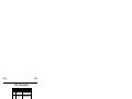
2.6.1 ADJUST1PPS ............................................................................................. 42
2.6.2 ANTENNAPOWER...................................................................................... 46
2.6.3 ASSIGN ....................................................................................................... 47
2.6.4 ASSIGNALL................................................................................................. 49
2.6.5 ASSIGNLBAND ........................................................................................... 51
2.6.6 AUTH........................................................................................................... 53
2.6.7 CLOCKADJUST .......................................................................................... 55
2.6.8 CLOCKCALIBRATE .................................................................................... 56
2.6.9 CLOCKOFFSET .......................................................................................... 58
2.6.10 COM .......................................................................................................... 59
2.6.11 COMCONTROL......................................................................................... 61
2.6.12 CSMOOTH ................................................................................................ 63
2.6.13 DATUM...................................................................................................... 64
2.6.14 DGPSEPHEMDELAY DGPS .................................................................. 68
2.6.15 DGPSRXID................................................................................................ 69
2.6.16 DGPSTIMEOUT DGPS .......................................................................... 70
2.6.17 DGPSTXID DGPS .................................................................................. 71
2.6.18 DYNAMICS................................................................................................ 72
2.6.19 ECUTOFF.................................................................................................. 73
2.6.20 EXTERNALCLOCK ................................................................................... 74
2.6.21 FIX ............................................................................................................. 77
OEM4 Family Firmware Version 2.300 Command and Log Reference Rev 16
3
Table of Contents
2.6.22 FIXPOSDATUM ........................................................................................ 80
2.6.23 FREQUENCYOUT.................................................................................... 81
2.6.24 FRESET.................................................................................................... 83
2.6.25 GGAQUALITY........................................................................................... 84
2.6.26 HPSEED ................................................................................................... 85
2.6.27 HPSTATICINIT ......................................................................................... 86
2.6.28 INTERFACEMODE DGPS ..................................................................... 87
2.6.29 LOCKOUT................................................................................................. 89
2.6.30 LOG .......................................................................................................... 90
2.6.31 MAGVAR .................................................................................................. 93
2.6.32 MARKCONTROL ...................................................................................... 95
2.6.33 MODEL ..................................................................................................... 97
2.6.34 MOVINGBASESTATION .......................................................................... 98
2.6.35 NVMRESTORE......................................................................................... 99
2.6.36 POSAVE ................................................................................................. 100
2.6.37 POSTIMEOUT ........................................................................................ 101
2.6.38 PPSCONTROL ....................................................................................... 102
2.6.39 PSRDIFFSOURCE DGPS ................................................................... 103
2.6.40 RESET .................................................................................................... 105
2.6.41 RTKBASELINE RTK ............................................................................ 106
2.6.42 RTKCOMMAND RTK ........................................................................... 108
2.6.43 RTKDYNAMICS RTK ........................................................................... 109
2.6.44 RTKELEVMASK RTK........................................................................... 110
2.6.45 RTKSOLUTION RTK............................................................................ 111
2.6.46 RTKSOURCE RTK............................................................................... 112
2.6.47 RTKSVENTRIES RTK.......................................................................... 113
2.6.48 SAVECONFIG ........................................................................................ 114
2.6.49 SBASCONTROL SBAS........................................................................ 115
2.6.50 SEND ...................................................................................................... 117
2.6.51 SENDHEX............................................................................................... 119
2.6.52 SETAPPROXPOS .................................................................................. 120
2.6.53 SETAPPROXTIME ................................................................................. 121
2.6.54 SETNAV.................................................................................................. 122
2.6.55 SETRTCM16 DGPS & RTK ................................................................. 124
2.6.56 STATUSCONFIG.................................................................................... 125
2.6.57 UNASSIGN ............................................................................................. 126
2.6.58 UNASSIGNALL....................................................................................... 126
2.6.59 UNDULATION......................................................................................... 127
2.6.60 UNLOCKOUT ......................................................................................... 128
2.6.61 UNLOCKOUTALL ................................................................................... 128
2.6.62 UNLOG ................................................................................................... 129
2.6.63 UNLOGALL............................................................................................. 130
2.6.64 USERDATUM ......................................................................................... 131
2.6.65 USEREXPDATUM .................................................................................. 132
2.6.66 UTMZONE .............................................................................................. 133
2.6.67 WAASCORRECTION SBAS ................................................................ 134
2.6.68 WAASECUTOFF .................................................................................... 135
3 Data Logs
136
3.1 Log Types........................................................................................................... 136
4
OEM4 Family Firmware Version 2.300 Command and Log Reference Rev 16
Table of Contents
3.2 Logs By Function ................................................................................................ 136
3.3 MiLLennium GPSCard Compatibility .................................................................. 153
3.4 Log Reference .................................................................................................... 153
3.4.1 ALMANAC Decoded Almanac ................................................................ 154
3.4.2 AVEPOS Position Averaging .................................................................. 156
3.4.3 BESTPOS Best Position ......................................................................... 158
3.4.4 BESTUTM Best Available UTM Data...................................................... 161
3.4.5 BESTVEL Best Available Velocity Data.................................................. 163
3.4.6 BESTXYZ
Best Available Cartesian Position and Velocity ................. 165
3.4.7 BSLNXYZ RTK XYZ Baseline RTK...................................................... 168
3.4.8 CLOCKMODEL Current Clock Model Status.......................................... 169
3.4.9 CLOCKSTEERING Clock Steering Status.............................................. 171
3.4.10 CMR Standard Logs RTK ..................................................................... 173
3.4.11 CMRDATADESC Base Station Description RTK ............................... 174
3.4.12 CMRDATAOBS Base Station Satellite Observations RTK ................ 176
3.4.13 CMRDATAREF Base Station Position RTK ....................................... 178
3.4.14 CMRPLUS CMR+ Output Message RTK ........................................... 180
3.4.15 COMCONFIG Current COM Port Configuration ................................... 181
3.4.16 GPALM Almanac Data NMEA............................................................ 182
3.4.17 GPGGA GPS Fix Data and Undulation NMEA................................... 184
3.4.18 GPGGALONG Fix Data, Extra Precision and Undulation NMEA....... 186
3.4.19 GPGGARTK Global Position System Fix Data NMEA ....................... 188
3.4.20 GPGLL Geographic Position NMEA................................................... 190
3.4.21 GPGRS GPS Range Residuals for Each Satellite NMEA.................. 191
3.4.22 GPGSA GPS DOP and Active Satellites NMEA ................................ 192
3.4.23 GPGST Pseudorange Measurement Noise Statistics NMEA ............ 193
3.4.24 GPGSV GPS Satellites in View NMEA .............................................. 194
3.4.25 GPRMB Navigation Information NMEA.............................................. 195
3.4.26 GPRMC GPS Specific Information NMEA ......................................... 196
3.4.27 GPSEPHEM Decoded GPS Ephemerides ........................................... 197
3.4.28 GPVTG Track Made Good And Ground Speed NMEA...................... 200
3.4.29 GPZDA UTC Time and Date NMEA................................................... 201
3.4.30 IONUTC Ionospheric and UTC Data..................................................... 202
3.4.31 LBANDINFO L-Band Configuration Information ................................... 203
3.4.32 LBANDSTAT L-Band Status Information .............................................. 205
3.4.33 LOGLIST List of System Logs .............................................................. 208
3.4.34 MARKPOS, MARK2POS Position at Time of Mark Input Event ........... 210
3.4.35 MARKTIME, MARK2TIME Time of Mark Input Event........................... 212
3.4.36 MATCHEDPOS Matched RTK Position RTK ..................................... 213
3.4.37 MATCHEDXYZ Matched RTK Cartesian Position RTK ..................... 215
3.4.38 NAVIGATE User Navigation Data......................................................... 217
3.4.39 NMEA Standard Logs.............................................................................. 219
3.4.40 OMNIHPPOS OmniSTAR HP Position ................................................. 220
3.4.41 PASSCOM, PASSXCOM, PASSAUX, PASSUSB Redirect Data......... 222
3.4.42 PORTSTATS Port Statistics ................................................................. 224
3.4.43 PSRDOP Pseudorange DOP................................................................ 226
3.4.44 PSRPOS Pseudorange Position........................................................... 227
3.4.45 PSRVEL Pseudorange Velocity............................................................ 228
3.4.46 PSRXYZ Pseudorange Cartesian Position and Velocity ...................... 230
OEM4 Family Firmware Version 2.300 Command and Log Reference Rev 16
5
Table of Contents
3.4.47 RANGE Satellite Range Information .................................................... 232
3.4.48 RANGECMP Compressed Version of the RANGE Log ....................... 236
3.4.49 RANGEGPSL1 L1 Version of the RANGE Log .................................... 238
3.4.50 RAWALM Raw Almanac Data.............................................................. 239
3.4.51 RAWEPHEM Raw Ephemeris.............................................................. 240
3.4.52 RAWGPSSUBFRAME Raw Subframe Data ........................................ 241
3.4.53 RAWGPSWORD Raw Navigation Word .............................................. 242
3.4.54 RAWLBANDFRAME Raw L-Band Frame Data.................................... 243
3.4.55 RAWLBANDPACKET Raw L-Band Data Packet ................................. 244
3.4.56 RAWWAASFRAME Raw SBAS Frame Data SBAS.......................... 245
3.4.57 REFSTATION Base Station Position and Health RTK ...................... 246
3.4.58 RTCA Standard Logs DGPS ................................................................ 248
3.4.59 RTCADATA1 Differential GPS Corrections DGPS ............................ 249
3.4.60 RTCADATAEPHEM Ephemeris and Time Information DGPS & RTK250
3.4.61 RTCADATAOBS Base Station Observations RTK ............................ 251
3.4.62 RTCADATAREF Base Station Parameters RTK ............................... 253
3.4.63 RTCM Standard Logs DGPS ............................................................... 254
3.4.64 RTCMDATA1 Differential GPS Corrections DGPS ........................... 256
3.4.65 RTCMDATA3 Base Station Parameters RTK.................................... 257
3.4.66 RTCMDATA9 Partial Differential GPS Corrections DGPS ................ 258
3.4.67 RTCMDATA15 Ionospheric Corrections DGPS................................. 259
3.4.68 RTCMDATA16 Special Message DGPS & RTK................................ 260
3.4.69 RTCMDATA1819 Raw Measurements RTK...................................... 261
3.4.70 RTCMDATA2021 Measurement Corrections RTK ............................ 265
3.4.71 RTCMDATA22 Extended Base Station RTK ..................................... 269
3.4.72 RTCMDATA59 Type 59N-0 NovAtel RT20 Differential RTK ............. 270
3.4.73 RTCMV3 RTCMV3 Standard Logs RTK............................................ 272
3.4.74 RTCMDATA1001 L1-Only GPS RTK Observables RTK ................... 273
3.4.75 RTCMDATA1002 Extended L1-Only GPS RTK Observables RTK... 276
3.4.76 RTCMDATA1003 L1/L2 GPS RTK Observables RTK....................... 278
3.4.77 RTCMDATA1004 Expanded L1/L2 GPS RTK Observables RTK ..... 280
3.4.78 RTCMDATA1005 Base Station Antenna Reference Point (ARP) RTK282
3.4.79 RTCMDATA1006 Base Station ARP with Antenna Height RTK........ 283
3.4.80 RTKDATA RTK Solution Parameters RTK ........................................ 284
3.4.81 RTKPOS RTK Low Latency Position Data RTK................................... 287
3.4.82 RTKVEL RTK Velocity RTK............................................................... 289
3.4.83 RTKXYZ RTK Cartesian Position and Velocity RTK ......................... 291
3.4.84 RXCONFIG Receiver Configuration..................................................... 293
3.4.85 RXHWLEVELS Receiver Hardware Levels.......................................... 295
3.4.86 RXSTATUS Receiver Status................................................................ 296
3.4.87 RXSTATUSEVENT Status Event Indicator .......................................... 301
3.4.88 SATVIS Satellite Visibility..................................................................... 303
3.4.89 SATXYZ SV Position in ECEF Cartesian Coordinates......................... 304
3.4.90 TIME Time Data ................................................................................... 305
3.4.91 TIMESYNC Synchronize Time Between GPS Receivers .................... 306
3.4.92 TRACKSTAT Tracking Status .............................................................. 307
3.4.93 VALIDMODELS Valid Model Information................................................ 309
3.4.94 VERSION Version Information ............................................................. 310
3.4.95 WAAS0 Remove PRN from Solution SBAS ...................................... 313
6
OEM4 Family Firmware Version 2.300 Command and Log Reference Rev 16
Table of Contents
3.4.96 WAAS1 PRN Mask Assignments SBAS ............................................ 314
3.4.97 WAAS2 Fast Correction Slots 0-12 SBAS ......................................... 315
3.4.98 WAAS3 Fast Corrections Slots 13-25 SBAS...................................... 317
3.4.99 WAAS4 Fast Correction Slots 26-38 SBAS ....................................... 319
3.4.100 WAAS5 Fast Correction Slots 39-50 SBAS ..................................... 321
3.4.101 WAAS6 Integrity Message SBAS..................................................... 323
3.4.102 WAAS7 Fast Correction Degradation SBAS .................................... 325
3.4.103 WAAS9 GEO Navigation Message SBAS........................................ 327
3.4.104 WAAS10 Degradation Factor SBAS ................................................ 328
3.4.105 WAAS12 SBAS Network Time and UTC SBAS ............................... 329
3.4.106 WAAS17 GEO Almanac Message SBAS......................................... 330
3.4.107 WAAS18 IGP Mask SBAS ............................................................... 331
3.4.108 WAAS24 Mixed Fast/Slow Corrections SBAS ................................. 332
3.4.109 WAAS25 Long-Term Slow Satellite Corrections SBAS.................... 334
3.4.110 WAAS26 Ionospheric Delay Corrections SBAS ............................... 336
3.4.111 WAAS27 SBAS Service Message SBAS ......................................... 337
3.4.112 WAAS32 CDGPS Fast Correction Slots 0-10 CDGPS .................... 338
3.4.113 WAAS33 CDGPS Fast Correction Slots 11-21 CDGPS .................. 340
3.4.114 WAAS34 CDGPS Fast Correction Slots 22-32 CDGPS .................. 341
3.4.115 WAAS35 CDGPS Fast Correction Slots 33-43 CDGPS .................. 342
3.4.116 WAAS45 CDGPS Slow Corrections CDGPS ................................... 343
3.4.117 WAASCORR SBAS Range Corrections Used SBAS....................... 344
4 Responses
OEM4 Family Firmware Version 2.300 Command and Log Reference Rev 16
345
7
Figures
1
2
3
4
5
6
7
8
9
8
1PPS Alignment ........................................................................................................42
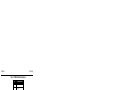
Pulse Width and 1PPS Coherency ............................................................................82
Illustration of Magnetic Variation & Correction ..........................................................94
TTL Pulse Polarity .....................................................................................................96
Using the SEND Command .....................................................................................118
Illustration of SETNAV Parameters .........................................................................123
Illustration of Undulation ..........................................................................................127
The WGS84 ECEF Coordinate System ...................................................................167
Navigation Parameters ............................................................................................217
OEM4 Family Firmware Version 2.300 Command and Log Reference Rev 16
Tables
1
2
3
4
5
6
7
8
9
10
11
12
13
14
15
16
17
18
19
20
21
22
23
24
25
26
27
28
29
30
31
32
33
34
35
36
37
38
39
40
41
42
43
44
Field Types .................................................................................................................13
Byte Arrangements.....................................................................................................14
ASCII Message Header Structure ..............................................................................15
Binary Message Header Structure .............................................................................17
Detailed Serial Port Identifiers ....................................................................................18
Binary Message Sequence.........................................................................................21
GPS Time Status .......................................................................................................21
Commands By Function Table ...................................................................................27
OEM4 Family Commands in Alphabetical Order........................................................31
OEM4 Family Commands in Order of their Message IDs ..........................................35
OEM4 Family Command Comparison........................................................................39
Channel State.............................................................................................................47
Channel System .........................................................................................................50
L-Band Mode ..............................................................................................................52
COM Serial Port Identifiers.........................................................................................60
Parity ..........................................................................................................................60
Handshaking...............................................................................................................60
Tx and DTR Availability ..............................................................................................62
Reference Ellipsoid Constants ...................................................................................65
Datum Transformation Parameters ............................................................................65
User Dynamics ...........................................................................................................72
Clock Type..................................................................................................................76
Pre-Defined Values for Oscillators .............................................................................76
FIX Parameters .........................................................................................................78
Fix Types ....................................................................................................................78
FRESET Target ..........................................................................................................83
Seeding Mode ............................................................................................................85
Serial Port Interface Modes ........................................................................................88
LOG Command Binary Format...................................................................................90
LOG Command ASCII Format....................................................................................92
DGPS Type ..............................................................................................................104
Baseline Parameters ................................................................................................106
Baseline Type...........................................................................................................107
Dynamics Mode........................................................................................................109
Type of Carrier Phase Ambiguity..............................................................................111
System Types...........................................................................................................116
Mask Types ..............................................................................................................125
UNLOG Command ASCII Format ............................................................................129
UNLOG Command Binary Format............................................................................129
UTM Zone Commands .............................................................................................133
Log Type Triggers ....................................................................................................136
Logs By Function Table............................................................................................137
OEM4 Family Logs in Alphabetical Order ................................................................143
OEM4 Family Logs in Order of their Message IDs ...................................................148
OEM4 Family Firmware Version 2.300 Command and Log Reference Rev 16
9
Tables
45
46
47
48
49
50
51
52
53
54
55
56
57
58
59
60
61
62
63
64
65
66
67
68
69
70
71
72
73
74
75
76
77
78
79
80
81
82
83
84
85
86
87
88
89
90
91
92
10
MiLLennium OEM3 Log Comparison .......................................................................153
Position Averaging Status ........................................................................................157
Position or Velocity Type ..........................................................................................159
Solution Status .........................................................................................................160
Clock Model Status...................................................................................................169
Clock Source ............................................................................................................172
Steering State...........................................................................................................172
Position Accuracy .....................................................................................................179
Position Precision of NMEA Logs.............................................................................190
URA Variance...........................................................................................................198
L-Band Subscription Type ........................................................................................204
L-Band Signal Tracking Status .................................................................................206
OmniSTAR VBS Status Word ..................................................................................206
OmniSTAR HP Additional Status Word....................................................................207
OmniSTAR HP Status Word.....................................................................................207
LOGLIST ASCII Format............................................................................................209
Navigation Data Type ...............................................................................................217
Channel Tracking Status ..........................................................................................233
Channel Tracking Example ......................................................................................235
Tracking State ..........................................................................................................235
Correlator Spacing....................................................................................................235
Range Record Format (RANGECMP only) ..............................................................237
Base Station Status ..................................................................................................247
Base Station Type ....................................................................................................247
RTCM1819 Data Quality Indicator............................................................................263
RTCM1819 Smoothing Interval ................................................................................264
RTCM1819 Multipath Indicator.................................................................................264
RTCM2021 Data Quality Indicator............................................................................268
RTCM2021 Multipath Indicator.................................................................................268
Carrier Smoothing Interval of Code Phase...............................................................274
Lock Time Indicator ..................................................................................................274
Searcher Type ..........................................................................................................286
Ambiguity Type.........................................................................................................286
RTK Information .......................................................................................................286
Receiver Hardware Parameters ..............................................................................295
Receiver Error ..........................................................................................................298
Receiver Status ........................................................................................................299
Auxiliary 1 Status......................................................................................................300
Auxiliary 2 Status......................................................................................................300
Auxiliary 3 Status......................................................................................................300
Status Word..............................................................................................................302
Event Type ...............................................................................................................302
Range Reject Code ..................................................................................................308
Component Types ....................................................................................................311
VERSION Log: Field Formats ..................................................................................312
Evaluation of UDREI.................................................................................................316
Evaluation of CDGPS UDREI...................................................................................339
Response Messages ................................................................................................345
OEM4 Family Firmware Version 2.300 Command and Log Reference Rev 16
Foreword
Foreword
Whether you have bought a stand alone GPSCard or a packaged receiver you will have also received
companion documents to this manual. They will help you get the hardware operational. Afterwards,
this text will be your primary OEM4 family command and logging reference.
Scope
This manual describes each command and log that the OEM4 family of receivers are capable of
accepting or generating. Sufficient detail is provided so that you should understand the purpose,
syntax, and structure of each command or log and be able to effectively communicate with the
receiver, thus enabling you to effectively use and write custom interfacing software for specific needs
and applications. The manual is organized into chapters which allow easy access to appropriate
information about the receiver.
There is also Satellite Based Augmentation System (SBAS) signal functionality. Please refer to the
SBAS Overview in Volume 1 of this manual set and the Conventions section below for more
information.
This manual does not address any of the receiver hardware attributes or installation information.
Please consult Volume 1 of this manual set for technical information on these topics. Furthermore,
should you encounter any functional, operational, or interfacing difficulties with the receiver, consult
Volume 1 of this manual set for NovAtel warranty and customer support information.
User Manual Updates
The most up-to-date version of this manual set and addendums can be downloaded from the
Documentation Updates section of www.novatel.com.
Prerequisites
As this reference manual is focused on the OEM4 family commands and logging protocol, it is
necessary to ensure that the receiver has been properly installed and powered up according to the
instructions outlined in the companion OEM4 Family User Manual Volume 1 before proceeding.
Conventions
This manual covers the full performance capabilities of all OEM4 family of receivers. Feature-tagging
symbols have been created to help clarify which commands and logs are only available with the RT-2
or RT-20 option or if there is only partial implementation of this feature:
RTK
DGPS
NMEA
SBAS
Features available only with receivers equipped with the RT-20 or RT-2 option
Feature used when operating in differential mode
National Marine Electronics Association format, see Message Formats in Volume 1 of this manual set
SBAS messages can be generated if you have an SBAS capable receiver model and are tracking an
SBAS satellite. For more information refer to the SBAS Overview in Volume 1 of this manual set.
Other simple conventions are:
OEM4 Family Firmware Version 2.300 Command and Log Reference Rev 16
11
Foreword
H
0x
The letter H in the Binary Byte or Binary Offset columns of the commands and logs tables represents
the header length for that command or log, see Section 1.1.3, Binary on Page 16
The number following 0x is a hexadecimal number
When default values are shown in command tables, they indicate the assumed values when optional
parameters have been omitted. Default values do not imply the factory default settings, see Chapter 2,
Page 40 for a list of factory default settings.
Command descriptions use the bracket symbols, [ ], to represent the optionality of parameters.
In tables where values are missing they should be assumed to be reserved for future use.
Status words are output as hexadecimal numbers and must be converted to binary format (and in some
cases then also to decimal). For an example of this type of conversion, please see the RANGE log,
Table 63, Channel Tracking Example on Page 235. Conversions and their binary or decimal results
are always read from right to left. For a complete list of hexadecimal, binary and decimal equivalents,
please refer to the Unit Conversion section of the GPS+ Reference Manual available on our website at
http://www.novatel.com/Downloads/docupdates.html.
ASCII log examples may be split over several lines for readability. In reality only a single [CR][LF]
pair is transmitted at the end of an ASCII log.
The terms OEM4-G2, and OEM4-G2L will not be used in this manual unless a specific detail refers to
it alone. The term receiver will infer that the text is applicable to an OEM4-G2L, or OEM4-G2, either
stand-alone or in an enclosure, unless otherwise stated.
All of the relevant SBAS commands and logs start with WAAS except for RAWWAASFRAME.
Generally, the PRN field of the WAASx logs is common, and indicates the SBAS satellite that the
message originated from. Please refer to the RTCA document RTCA D0-229B, Appendix A Wide Area
Augmentation System Signal Specification for detail on the SBAS logs.
What’s New in Firmware Version 2.300 Since Version 2.210
12
1.
RTCM Version 3.0 logs are added: RTCM1001, RTCM1002, RTCM1003, RTCM1004,
RTCM1005 and RTCM1006. Each has its own data message, see the RTCMDATA100x messages
and the RTCMV3 logs starting on Page 272. The CMRPLUS log is new, see Page 180. The
Serial Port Interface Modes on Page 88 and DGPS Type on Page 104 tables are updated for them.
2.
The datum table is revised where many datum values are either updated or corrected. Please see
Table 20 starting on Page 65. The FIXPOSDATUM and USEREXPDATUM commands, see
Pages 80 and 132 respectively, are also added.
3.
The EGM96 ellipsoid model is added, see the UNDULATION command on Page 127.
4.
Universal Transverse Mercator (UTM) coordinate messages are added. See the UTMZONE
command on Page 133 and the BESTUTM log on Page 161.
5.
There are two new commands for OmniSTAR HP users. See the HPSEED and the
HPSTATICINIT commands on Page 85 and 86 respectively.
6.
MOVINGBASESTATION, Page 98, and POSTIMEOUT, Page 101, commands are also new.
7.
The new WAASECUTOFF command, Page 135, is added for SBAS users.
8.
The Serial Port Interface Modes on Page 88 is also updated for a binary only mode
(NOVATELBINARY).
OEM4 Family Firmware Version 2.300 Command and Log Reference Rev 16
Chapter 1
1.1
Messages
Message Types
The receiver handles all incoming and outgoing NovAtel data in three different message formats:
Abbreviated ASCII, ASCII, and Binary. This allows for a great deal of versatility in the way the
OEM4 family receivers can be used. All NovAtel commands and logs can be entered, transmitted,
output or received in any of the three formats. The receiver also supports RTCA, RTCMV3, RTCM,
CMR and NMEA format messaging, see the chapter on Message Formats in Volume 1 of this manual
set.
When entering an ASCII or abbreviated ASCII command in order to request an output log, the
message type is indicated by the character appended to the end of the message name. ‘A’ indicates that
the message is ASCII and ‘B’ indicates that it is binary. No character means that the message is
Abbreviated ASCII. When issuing binary commands the output message type is dependant on the bit
format in the message’s binary header, see Binary on Page 16.
The following table describes the field types used in the description of messages.
Table 1: Field Types
Type
Binary
Size
(bytes)
Char
1
UChar
1
Short
UShort
Long
ULong
2
2
4
4
Double
8
Float
4
Enum
4
GPSec
4
Hex
n
String
n
Description
The char type is an 8-bit integer in the range -128 to +127. This integer value may be
the ASCII code corresponding to the specified character. In ASCII or Abbreviated
ASCII this comes out as an actual character.
The uchar type is an 8-bit unsigned integer. Values are in the range from +0 to +255. In
ASCII or Abbreviated ASCII this comes out as a number.
The short type is 16-bit integer in the range -32768 to +32767.
The same as Short except that it is not signed. Values are in the range from +0 to +65535.
The long type is 32-bit integer in the range -2147483648 to +2147483647.
The same as Long except that it is not signed. Values are in the range from +0 to
+4294967295.
The double type contains 64 bits: 1 for sign, 11 for the exponent, and 52 for the mantissa.
Its range is ±1.7E308 with at least 15 digits of precision. This is IEEE 754.
The float type contains 32 bits: 1 for the sign, 8 for the exponent, and 23 for the mantissa.
Its range is ±3.4E38 with at least 7 digits of precision. This is IEEE 754.
A 4-byte enumerated type beginning at zero (an unsigned long). In binary, the
enumerated value is output. In ASCII or Abbreviated ASCII, the enumeration label is
spelled out.
This type has two separate formats that depend on whether you have requested a binary
or an ASCII format output. For binary the output is in milliseconds and is a long type.
For ASCII the output is in seconds and is a float type.
Hex is a packed, fixed length (n) array of bytes in binary but in ASCII or Abbreviated
ASCII is converted into 2 character hexadecimal pairs.
String is a variable length array of bytes that is null-terminated in the binary case and
additional bytes of padding are added to maintain 4 byte alignment. The maximum byte
length for each String field is shown in their row in the log or command tables.
OEM4 Family Firmware Version 2.300 Command and Log Reference Rev 16
13
Chapter 1
Messages
Table 2: Byte Arrangements
7
0
char
address n
15
7
0
short
n + 1 address n
31
23
15
7
long
tw o's compliment
double
float
0
n+3
n+2
n+1
63 62
52 51
S Biased Exponent|
address n
0
52-bits mantissa
n+7
n+6
n+5
n+4
n+3
31 30
23 22
0
S Biased Exponent| 23-bits mantissa
n+3
n+2
n + 1 address n
n+2
n+1
address n
Table 2 shows the arrangement of bytes within each field type when used by IBM PC computers. All
data sent to or from the OEM4 family receiver, however, is read least significant bit (LSB) first,
opposite to what is shown in Table 2. Data is then stored in the receiver LSB first. For example, in
char type data, the LSB is bit 0 and the most significant bit (MSB) is bit 7. See Table 63, Channel
Tracking Example on Page 235 for a more detailed example.
1.1.1
ASCII
ASCII messages are readable by both the user and a computer. The structures of all ASCII messages
follow the general conventions as noted here:
14
1.
The lead code identifier for each record is '#'.
2.
Each log or command is of variable length depending on amount of data and formats.
3.
All data fields are delimited by a comma ',' with two exceptions. The first exception
is the last header field which is followed by a ; to denote the start of the data message.
The other exception is the last data field, which is followed by a * to indicate end of
message data.
4.
Each log ends with a hexadecimal number preceded by an asterisk and followed by
a line termination using the carriage return and line feed characters, for example,
*1234ABCD[CR][LF]. This value is a 32-bit CRC of all bytes in the log, excluding
the '#' identifier and the asterisk preceding the four checksum digits. See 32-Bit CRC
on Page 24 for the algorithm used to generate the CRC.
5.
An ASCII string is one field and is surrounded by double quotation marks, for
example, “ASCII string”. If separators are surrounded by quotation marks then the
string is still one field and the separator will be ignored, for example, “xxx,xxx” is
one field. Double quotation marks within a string are not allowed.
6.
If the receiver detects an error parsing an input message, it will return an error
response message. Please see Chapter 4, Responses on Page 345 for a list of
response messages from the receiver.
OEM4 Family Firmware Version 2.300 Command and Log Reference Rev 16
Messages
Chapter 1
Message Structure:
header;
data field...,
data field...,
data field...
*xxxxxxxx
[CR][LF]
The ASCII message header is formatted as follows:
Table 3: ASCII Message Header Structure
Field # Field Name
Field Type
1
Sync
Char
2
Message
Char
3
Port
Char
4
Sequence #
Long
5
% Idle Time
Float
6
GPS Time
Status
Week
Seconds
Enum
9
Receiver
Status
Ulong
10
11
Reserved
Receiver
s/w Version
;
Ulong
Ulong
7
8
12
Ulong
GPSec
Char
Description
Sync character. The ASCII message is always preceded by
a single ‘#’ symbol.
This is the ASCII name of the log (see a list of all the logs
in Table 42, Logs By Function Table on Page 137).
This is the name of the port from which the log was
generated. The string is made up of the port name followed
by an _x where x is a number from 1 to 31 denoting the
virtual address of the port. If no virtual address is
indicated, it is assumed to be address 0.
This is used for multiple related logs. It is a number that
counts down from N-1 to 0 where 0 means it is the last one
of the set. Most logs only come out one at a time in which
case this number is 0.
The minimum percentage of time that the processor is idle
between successive logs with the same Message ID.
This value indicates the quality of the GPS time (see Table
7, GPS Time Status on Page 21)
GPS week number.
Seconds from the beginning of the GPS week accurate to
the millisecond level.
This is an eight digit hexadecimal number representing the
status of various hardware and software components of the
receiver between successive logs with the same Message
ID (see Table 81, Receiver Status on Page 299).
Reserved for internal use.
This is a value (0 - 65535) that represents the receiver
software build number.
This character indicates the end of the header.
Ignored
on Input
N
N
Y
N
Y
Y
Y
Y
Y
Y
Y
N
Example Log:
#RAWEPHEMA,COM1,0,81.5,SATTIME,1262,488670.000,00000000,97b7,1522;
14,1262,489600,8b03b89f13253b90002ba3db7949b427b21dbe7aeae6778800fffefd9748,8b0
3b89f112ae609952f1d85e6f79c087000cba26308b6a10cad2977887d,8b03b89f11ac0000acd77
614fff927cc00c026b4c6904cdaffa6c3e610b0*bccbb2db[CR][LF]
OEM4 Family Firmware Version 2.300 Command and Log Reference Rev 16
15
Chapter 1
1.1.2
Messages
Abbreviated ASCII
This message format is designed to make the entering and viewing of commands and logs by the user
as simple as possible. The data is represented as simple ASCII characters separated by spaces or
commas and arranged in an easy to understand fashion. There is also no 32-bit CRC for error
detection because it is meant for viewing by the user.
Example Command:
log com1 loglist
Resultant Log:
<LOGLIST COM1 0 69.0 FINE 0 0.000 00240000 206d 0
<
4
<
COM1 RXSTATUSEVENTA ONNEW 0.000000 0.000000 NOHOLD
<
COM2 RXSTATUSEVENTA ONNEW 0.000000 0.000000 NOHOLD
<
COM3 RXSTATUSEVENTA ONNEW 0.000000 0.000000 NOHOLD
<
COM1 LOGLIST ONCE 0.000000 0.000000 NOHOLD
As you can see the array of 4 logs are offset from the left hand side and start with ‘<’.
1.1.3
Binary
Binary messages are meant strictly as a machine readable format. They are also ideal for applications
where the amount of data being transmitted is fairly high. Because of the inherent compactness of
binary as opposed to ASCII data, the messages are much smaller. This allows a larger amount of data
to be transmitted and received by the receiver’s communication ports. The structure of all Binary
messages follows the general conventions as noted here:
1.
Basic format of:
Header
2.
3 Sync bytes plus 25 bytes of header information. The header length is
variable as fields may be appended in the future. Always check the header
length.
Data
variable
CRC
4 bytes
The 3 Sync bytes will always be:
Byte
First
Second
Third
16
Hex
AA
44
12
Decimal
170
68
18
3.
The CRC is a 32-bit CRC (see 32-Bit CRC on Page 24 for the CRC algorithm)
performed on all data including the header.
4.
The header is in the format shown in Table 4, Binary Message Header Structure on
Page 17.
OEM4 Family Firmware Version 2.300 Command and Log Reference Rev 16
Messages
Chapter 1
Table 4: Binary Message Header Structure
Binary
Bytes
Binary
Offset
1
1
1
1
2
0
1
2
3
4
N
N
N
N
N
1
6
N
1
7
Nb
2
8
N
2
10
N
1
12
Y
1c
13
Nd
Ushort
Hexadecimal 0xAA.
Hexadecimal 0x44.
Hexadecimal 0x12.
Length of the header.
This is the Message ID number of the log (see the
log descriptions in Table 44, OEM4 Family Logs
in Order of their Message IDs on Page 148 for the
Message ID values of individual logs).
Bits 0-4 = Reserved
Bits 5-6 = Format
00 = Binary
01 = ASCII
10 = Abbreviated ASCII, NMEA
11 = Reserved
Bit 7
= Response bit (see Section 1.2, Page 20)
0 = Original Message
1 = Response Message
See Table 5 on Page 18 (decimal values greater
than 16 may be used) (lower 8 bits only) a
The length in bytes of the body of the message.
This does not include the header nor the CRC.
This is used for multiple related logs. It is a number
that counts down from N-1 to 0 where N is the
number of related logs and 0 means it is the last
one of the set. Most logs only come out one at a
time in which case this number is 0.
The time that the processor is idle in the last
second between successive logs with the same
Message ID. Take the time (0 - 200) and divide by
two to give the percentage of time (0 - 100%).
Indicates the quality of the GPS time (see Table 7,
GPS Time Status on Page 21).
GPS week number.
2
14
Nd
Milliseconds
GPSec
Milliseconds from the beginning of the GPS week.
4
16
14
Receiver
Status
Ulong
4
20
15
16
Reserved
Receiver
S/W Version
Ushort
Ushort
32 bits representing the status of various hardware
and software components of the receiver between
successive logs with the same Message ID (see
Table 81, Receiver Status on Page 299)
Reserved for internal use.
This is a value (0 - 65535) that represents the
receiver software build number.
Nd
Y
2
2
24
26
Y
Y
Field
#
Field Name
Field
Type
Description
1
2
3
4
5
Sync
Sync
Sync
Header Lgth
Message ID
Char
Char
Char
Uchar
Ushort
6
Message
Type
Char
7
Port Address
Uchar
8
Ushort
9
Message
Length
Sequence
10
Idle Time
Uchar
11
Time Status
Enum
12
Week
13
Ushort
Ignored
on Input
a. The 8 bit size means that you will only see 0xA0 to 0xBF when the top bits are dropped from a port
value greater than 8 bits. For example ASCII port USB1 will be seen as 0x5A in the binary output.
b. Recommended value is THISPORT (binary 192)
c. This ENUM is not 4 bytes long but, as indicated in the table, is only 1 byte.
d. These time fields are ignored if Field #11, Time Status, is invalid. In this case the current receiver
time is used. The recommended values for the three time fields are 0, 0, 0.
OEM4 Family Firmware Version 2.300 Command and Log Reference Rev 16
17
Chapter 1
Messages
Table 5: Detailed Serial Port Identifiers
Hex Port
Value
Decimal Port
Value a
NO_PORTS
0
0
No ports specified
COM1_ALL
1
1
All virtual ports for COM port 1
COM2_ALL
2
2
All virtual ports for COM port 2
COM3_ALL
3
3
All virtual ports for COM port 3
THISPORT_ALL
6
6
All virtual ports for the current port
ALL_PORTS
8
8
All virtual ports for all ports
XCOM1_ALL
9
9
All virtual COM1 ports
XCOM2_ALL
10
10
All virtual COM2 ports
USB1_ALL
d
13
All virtual ports for USB port 1
USB2_ALL
e
14
All virtual ports for USB port 2
USB3_ALL
f
15
All virtual ports for USB port 3
AUX_ALL
10
16
All virtual ports for the AUX port b
COM1
20
32
COM port 1, virtual port 0
COM1_1
...
COM1_31
21
33
COM port 1, virtual port 1
3f
63
COM port 1, virtual port 31
COM2
...
COM2_31
40
64
COM port 2, virtual port 0
5f
95
COM port 2, virtual port 31
COM3
...
COM3_31
60
96
COM port 3, virtual port 0
7f
127
COM port 3, virtual port 31
USB
...
USB_31
80
128
USB port, virtual port 0
9f
159
USB port, virtual port 31
SPECIAL
...
SPECIAL_31
a0
160
Unknown port, virtual port 0
bf
191
Unknown port, virtual port 31
THISPORT
...
THISPORT_31
c0
192
Current COM port, virtual port 0
df
223
Current COM port, virtual port 31
ASCII Port
Name
Description
XCOM1
1a0
416
Virtual COM1 port, virtual port 0
XCOM1_1
...
XCOM1_31
1a1
417
Virtual COM1 port, virtual port 1
1bf
447
Virtual COM1 port, virtual port 31
XCOM2
2a0
672
Virtual COM2 port, virtual port 0
Continued on Page 19
18
OEM4 Family Firmware Version 2.300 Command and Log Reference Rev 16
Messages
Chapter 1
Hex Port
Value
Decimal Port
Value a
XCOM2_1
...
XCOM2_31
2a1
673
Virtual COM2 port, virtual port 1
2bf
703
Virtual COM2 port, virtual port 31
USB1
5a0
1440
USB port 1, virtual port 0
USB1_1
...
USB1_31
5a1
1441
USB port 1, virtual port 1
5bf
1471
USB port 1, virtual port 31
USB2
...
USB2_31
6a0
1696
USB port 2, virtual port 0
6bf
1727
USB port 2, virtual port 31
USB3
...
USB3_31
7a0
1952
USB port 3, virtual port 0
7bf
1983
USB port 3, virtual port 31
AUX
8a0
2208
AUX port, virtual port 0 b
...
AUX_31
8bf
2239
AUX port, virtual port 31 b
ASCII Port
Name
Description
a. Decimal port values 0 through 16 are only available to the UNLOGALL command,
see Page 130, and cannot be used in the UNLOG command, Page 129, or in the
binary message header, see Table 4 on Page 17.
b. The AUX port is only available on OEM4-G2-based (hardware Rev. 3 and higher)
and DL-4 products.
COM1_ALL, COM2_ALL, COM3_ALL, THISPORT_ALL, ALL_PORTS, USB1_ALL,
USB2_ALL, USB3_ALL and AUX_ALL are only valid for the UNLOGALL command.
OEM4 Family Firmware Version 2.300 Command and Log Reference Rev 16
19
Chapter 1
1.2
Messages
Responses
By default, if you input a message you will get back a response. If desired, the INTERFACEMODE
command can be used to disable response messages (see Page 87). The response will be in the exact
format that you entered the message (that is, binary input = binary response).
Abbreviated Response
Just the leading '<' followed by the response string, for example:
<OK
ASCII Response
Full header with the message name being identical except ending in an 'R' (for response). The body of
the message consists of a 40 character string for the response string, for example:
#BESTPOSR,COM1,0,67.0,FINE,1028,422060.400,00000000,a31b,0;"OK" *b867caad
Binary Response
Similar to an ASCII response except that it follows the binary protocols:
•
•
•
Binary header with message type set to response value (for example, 0x82), see
Field 6 in Table 4, Binary Message Header Structure on Page 17.
ENUM response ID, see Table 92, Response Messages on Page 345.
String containing the ASCII response to match the ENUM response ID above (for
example, 0x4F04B = OK)
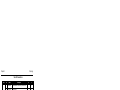
Table 6, Binary Message Sequence on Page 21 is an example of the sequence for requesting and then
receiving BESTPOSB. The example is in hex format. When you enter a hex command, you may need
to add a ‘\x’ or ‘0x’ before each hex pair, depending on your code (for example,
0xAA0x440x120x1C0x010x000x02 and so on).
20
OEM4 Family Firmware Version 2.300 Command and Log Reference Rev 16
Messages
Chapter 1
Table 6: Binary Message Sequence
Direction
Sequence
Data
LOG Command Header
To
Receiver
LOG Parameters
Checksum
From
Receiver
LOG Response Header
Log Response Data
Checksum
BESTPOSB Header
From
Receiver
BESTPOSB Data
Checksum
1.3
AA44121C 01000240 20000000 1D1D0000 29160000 00004C00
55525A80
20000000 2A000000 02000000 00000000 0000F03F 00000000
00000000 00000000
2304B3F1
AA44121C 01008220 06000000 FFB4EE04 605A0513 00004C00
FFFF5A80
01000000 4F4B
DA8688EC
AA44121C 2A000220 48000000 A5B4EE04 888F2013 00000000
A64CF205
00000000 10000000 2A11CF8F E68E4940 ED818CFE 73825CC0
00F0A903 A19A9040 732B82C1 3D000000 6F7DF33F BACFC33F
9DE58940 00000000 00000000 00000000 07070000 00000000
0C0458B7
GPS Time Status
All reported receiver times are subject to a qualifying time status. This status gives you an indication
of how well a time is known, see Table 7:
Table 7: GPS Time Status
GPS Time Status
(Decimal)
GPS Time Status a
(ASCII)
20
60
80
100
120
130
UNKNOWN
APPROXIMATE
COARSEADJUSTING
COARSE
COARSESTEERING
FREEWHEELING
140
160
180
200
FINEADJUSTING
FINE
FINESTEERING
SATTIME
Description
Time validity is unknown.
Time is set approximately.
Time is approaching coarse precision.
This time is valid to coarse precision.
Time is coarse set, and is being steered.
Position is lost, and the range bias cannot be
calculated.
Time is adjusting to fine precision.
Time has fine precision.
Time is fine, set and is being steered.
Time from satellite. This is only used in logs
containing satellite data such as ephemeris and
almanac.
a. See also Section 1.4, Message Time Stamps on Page 23
OEM4 Family Firmware Version 2.300 Command and Log Reference Rev 16
21
Chapter 1
Messages
There are several distinct states that the receiver will go through:
•
UNKNOWN
•
COARSE
•
FREEWHEELING
•
FINE
•
FINESTEERING
On start up, and before any satellites are being tracked, the receiver can not possibly know the current
time. As such, the receiver time starts counting at GPS week 0 and second 0.0. The time status flag is
set to UNKNOWN.
If time is input to the receiver using the SETAPPROXTIME command, see Page 121, or on receipt of
an RTCAEPHEM message, see Page 197, the time status will be APPROXIMATE.
After the first ephemeris is decoded, the receiver time is set to a resolution of ±10 milliseconds. This
state is qualified by the COARSE or COARSESTEERING time status flag depending on the state of
the CLOCKADJUST switch.
Once a position is known and range biases are being calculated, the internal clock model will begin
modelling the position range biases and the receiver clock offset.
Modelling will continue until the model is a good estimation of the actual receiver clock behavior. At
this time, the receiver time will again be adjusted, this time to an accuracy of ±1 microsecond. This
state is qualified by the FINE time status flag.
The final logical time status flag depends on whether CLOCKADJUST is enabled or not, see Page 55.
If CLOCKADJUST is disabled, the time status flag will never improve on FINE. The time will only
be adjusted again to within ±1 microsecond if the range bias gets larger than ±250 milliseconds. If
ClockAdjust is enabled, the time status flag will be set to FINE_STEERING and the receiver time will
be continuously updated (steered) to minimize the receiver range bias.
If for some reason position is lost and the range bias cannot be calculated, the time status will be
degraded to FREEWHEELING.
22
OEM4 Family Firmware Version 2.300 Command and Log Reference Rev 16
Messages
1.4
Chapter 1
Message Time Stamps
All NovAtel format messages generated by the OEM4 family receivers have a GPS time stamp in
their header. GPS time is referenced to UTC with zero point defined as midnight on the night of
January 5 1980. The time stamp consists of the number of weeks since that zero point and the number
of seconds since the last week number change (0 to 604,799). GPS time differs from UTC time since
leap seconds are occasionally inserted into UTC but GPS time is continuous. In addition a small error
(less than 1 microsecond) can exist in synchronization between UTC and GPS time. The TIME log
reports both GPS and UTC time and the offset between the two.
The data in synchronous logs (for example, RANGE, BESTPOS, TIME) are based on a periodic
measurement of satellite pseudoranges. The time stamp on these logs is the receiver estimate of GPS
time at the time of the measurement. When setting time in external equipment, a small synchronous
log with a high baud rate will be accurate to a fraction of a second. A synchronous log with trigger
ONTIME 1 can be used in conjunction with the 1PPS signal to provide relative accuracy better than
250 ns.
Other log types (asynchronous and polled) are triggered by an external event and the time in the
header may not be synchronized to the current GPS time. Logs that contain satellite broadcast data
(for example, ALMANAC, GPSEPHEM) have the transmit time of their last subframe in the header.
In the header of differential time matched logs (for example, MATCHEDPOS) is the time of the
matched reference and local observation that they are based on. Logs triggered by a mark event (for
example, MARKEDPOS, MARKTIME) have the estimated GPS time of the mark event in their
header. In the header of polled logs (for example, LOGLIST, PORTSTATS, VERSION) is the
approximate GPS time when their data was generated. However, when asynchronous logs are
triggered ONTIME, the time stamp will represent the time the log was generated, not the time given in
the data.
1.5
Decoding of the GPS Week Number
The GPS week number provided in the raw satellite data is the 10 least significant bits (or 8 least
significant bits in the case of the almanac data) of the full week number. When the receiver processes
the satellite data, the week number is decoded in the context of the current era and, therefore, is
computed as the full week number starting from week 0 or January 6, 1980. Therefore, in all log
headers and decoded week number fields, the full week number is given. Only in raw data, such as the
data field of the RAWALM log or the subframe field of the RAWEPHEM log, will the week number
remain as the 10 (or 8) least significant bits.
OEM4 Family Firmware Version 2.300 Command and Log Reference Rev 16
23
Chapter 1
1.6
Messages
32-Bit CRC
The ASCII and Binary OEM4 family message formats all contain a 32-bit CRC for data verification.
This allows the user to ensure that the data received (or transmitted) is valid with a high level of
certainty. This CRC can be generated using the following C algorithm:
#define CRC32_POLYNOMIAL 0xEDB88320L
/* -------------------------------------------------------------------------Calculate a CRC value to be used by CRC calculation functions.
-------------------------------------------------------------------------- */
unsigned long CRC32Value(int i)
{
int j;
unsigned long ulCRC;
ulCRC = i;
for ( j = 8 ; j > 0; j-- )
{
if ( ulCRC & 1 )
ulCRC = ( ulCRC >> 1 ) ^ CRC32_POLYNOMIAL;
else
ulCRC >>= 1;
}
return ulCRC;
}
/* -------------------------------------------------------------------------Calculates the CRC-32 of a block of data all at once
-------------------------------------------------------------------------- */
unsigned long CalculateBlockCRC32(
unsigned long ulCount,
/* Number of bytes in the data block */
unsigned char *ucBuffer ) /* Data block */
{
unsigned long ulTemp1;
unsigned long ulTemp2;
unsigned long ulCRC = 0;
while ( ulCount-- != 0 )
{
ulTemp1 = ( ulCRC >> 8 ) & 0x00FFFFFFL;
ulTemp2 = CRC32Value( ((int) ulCRC ^ *ucBuffer++ ) & 0xff );
ulCRC = ulTemp1 ^ ulTemp2;
}
return( ulCRC );
}
The NMEA checksum is an XOR of all the bytes (including delimiters such as ',' but excluding the * and $)
in the message output. It is therefore an 8-bit and not a 32-bit checksum for NMEA logs.
At the time of writing, a log may not yet be available. Every effort is made to ensure that examples are correct,
however, a checksum may be created for promptness in publication. In this case it will appear as ‘9999’.
24
OEM4 Family Firmware Version 2.300 Command and Log Reference Rev 16
Messages
Chapter 1
Example:
BESTPOSA and BESTPOSB from an OEM4 family receiver.
ASCII:
#BESTPOSA,COM2,0,77.5,FINESTEERING,1285,160578.000,00000020,5941,1164;
SOL_COMPUTED,SINGLE,51.11640941570,-114.03830951024,1062.6963,-16.2712,
WGS84,1.6890,1.2564,2.7826,"",0.000,0.000,10,10,0,0,0,0,0,0*2212A3C3
BINARY:
0xAA, 0x44, 0x12, 0x1C, 0x2A,0x 00, 0x02, 0x42, 0x48, 0x00, 0x00, 0x00, 0x96, 0xB4,
0x05, 0x05, 0x90, 0x32, 0x8E, 0x09, 0x20, 0x00, 0x00, 0x00, 0x41, 0x59, 0x8C, 0x04,
0x00, 0x00, 0x00, 0x00, 0x10, 0x00, 0x00, 0x00, 0x03, 0x9A, 0x8A, 0x8A, 0xE6, 0x8E,
0x49, 0x40, 0xEB, 0xD8, 0xE7, 0xB2, 0x73, 0x82, 0x5C, 0xC0, 0x00, 0xB0, 0xDD,
0xA2, 0x37,0x 9B, 0x90, 0x40, 0x80, 0x2B, 0x82, 0xC1, 0x3D, 0x00, 0x00, 0x00, 0x9D,
0xDA, 0x3F, 0xF7, 0x58, 0xA1, 0x3F, 0x3F, 0xF4, 0x32, 0x89, 0x40, 0x00, 0x00, 0x00,
0x00,0x00, 0x00, 0x00, 0x00, 0x00, 0x00, 0x00, 0x00, 0x0A, 0x0A, 0x00, 0x00, 0x00,
0x00, 0x00, 0x00, 0x880xF50x420x8D
Below is a demonstration of how to generate the CRC from both ASCII and BINARY
messages using the function described above.
When you pass the data into the code below, exclude the checksum shown in bold italics above.
ASCII:
#include <iostream.h>
#include <string.h>
void main()
{
char_*i_=_”BESTPOSA,COM2,0,77.5,FINESTEERING,1285,160578.000,00000020,5941,1164;
SOL_COMPUTED,SINGLE,51.11640941570,-114.03830951024,1062.6963,-16.2712,
WGS84,1.6890,1.2564,2.7826,"",0.000,0.000,10,10,0,0,0,0,0,0";
unsigned long iLen = strlen(i);
unsigned long CRC = CalculateBlockCRC32(iLen, (unsigned char*)i);
cout << hex << CRC <<endl;
}
BINARY:
#include <iostream.h>
#include <string.h>
int main()
{
unsigned char buffer[] = {0xAA, 0x44, 0x12, 0x1C, 0x2A,0x 00, 0x02, 0x42, 0x48, 0x00, 0x00, 0x00, 0x96, 0xB4, 0x05, 0x05,
0x90, 0x32, 0x8E, 0x09, 0x20, 0x00, 0x00, 0x00, 0x41, 0x59, 0x8C, 0x04, 0x00, 0x00, 0x00, 0x00, 0x10, 0x00, 0x00, 0x00,
0x03, 0x9A, 0x8A, 0x8A, 0xE6, 0x8E, 0x49, 0x40, 0xEB, 0xD8, 0xE7, 0xB2, 0x73, 0x82, 0x5C, 0xC0, 0x00, 0xB0, 0xDD,
0xA2, 0x37,0x 9B, 0x90, 0x40, 0x80, 0x2B, 0x82, 0xC1, 0x3D, 0x00, 0x00, 0x00, 0x9D, 0xDA, 0x3F, 0xF7, 0x58, 0xA1,
0x3F, 0x3F, 0xF4, 0x32, 0x89, 0x40, 0x00, 0x00, 0x00, 0x00,0x00, 0x00, 0x00, 0x00, 0x00, 0x00, 0x00, 0x00, 0x0A, 0x0A,
0x00, 0x00, 0x00, 0x00, 0x00, 0x00};
unsigned long crc = CalculateBlockCRC32(60, buffer);
cout << hex << crc <<endl;
//Please note that this hex needs to be reversed due to Big Endian order where the most significant value in the sequence is
stored first (at the lowest storage address). For example, the two bytes required for the hex number 4F52 is stored as 524F.
}
OEM4 Family Firmware Version 2.300 Command and Log Reference Rev 16
25
Chapter 2
2.1
Commands
Command Formats
The receiver will accept commands in 3 formats as described in Chapter 1:
•
Abbreviated ASCII
•
ASCII
•
Binary
Abbreviated ASCII is the easiest to use for your input. The other two formats include a CRC for error
checking and are intended for use when interfacing with other electronic equipment.
Here are examples of the same command in each format:
Abbreviated ASCII Example:
LOG COM2 BESTPOSB ONTIME 1[CR]
ASCII Example:
LOGA,COM2,0,66.0,UNKNOWN,0,15.917,004c0000,5255,32858;COM1,BESTPOSB,
ONTIME,1.000000,0.000000,NOHOLD*F95592DD[CR]
Binary Example:
AA44121C 01000240 20000000 1D1D0000 29160000 00004C00 55525A80 20000000
2A000000 02000000 00000000 0000F03F 00000000 00000000 00000000 2304B3F1
2.2
Command Settings
Their are several ways to determine the current command settings of the receiver:
1.
Request an RXCONFIG log, see Page 293. This will provide a listing of all
commands and their parameter settings. This log provides the most complete
information, but the size and format do not make it easy to read.
2.
For some specific commands, logs are available to indicate all their parameter
settings. The LOGLIST log, see Page 208, will show all active logs in the receiver
beginning with the LOG command. The COMCONFIG log, see Page 176, will show
both the COM and INTERFACEMODE commands parameter settings for all serial
ports.
3.
Request a log of the specific command of interest. This will show the parameters last
entered for that command. The format of the log produced is exactly the same as the
format of the specific command with updated header information.
4.
This is very useful for most commands, but for commands that are repeated with
different parameters (for example, COM, LOG, and INTERFACEMODE), this will
only show the most recent set of parameters used. To see all sets of parameters try
method 1 or 2 above.
OEM4 Family Firmware Version 2.300 Command and Log Reference Rev 16
26
Commands
Chapter 2
Abbreviated ASCII Example:
log fix
<FIX COM1 0 45.0 FINE 1114 151898.288 00200000 dbfd 33123
<
2.3
NONE -10000.00000000000 -10000.00000000000 -10000.0000
Commands by Function
Table 8 lists the commands by function while Table 9 on Page 31 is an alphabetical listing of
commands (repeated in Table 10 on Page 35 with the commands in the order of their message IDs).
Please see 2.6, Command Reference on Page 42 for a more detailed description of individual
commands which are listed alphabetically.
Table 8: Commands By Function Table
COMMUNICATIONS, CONTROL AND STATUS
Commands
Descriptions
ANTENNAPOWER
Control power to low-noise amplifier (LNA) of an active antenna
COM
Set COM port configuration
COMCONTROL
Control the hardware control lines of the RS232 ports
FREQUENCYOUT
Set the output pulse train available on VARF
INTERFACEMODE
Set interface type, Receive (Rx)/Transmit (Tx), for a port
LOG
Request a log
MARKCONTROL
Control processing of the mark inputs
PPSCONTROL
Control the PPS output
SEND
Send ASCII message to a port
SENDHEX
Send non-printable characters to a port
SETRTCM16
Enter ASCII message to be sent in RTCM data stream
UNLOG, UNLOGALL
Remove one or all logs from logging control
GENERAL RECEIVER CONTROL
Commands
Descriptions
AUTH
Add authorization code for new model
DYNAMICS
Tune receiver parameters
Continued on Page 28
OEM4 Family Firmware Version 2.300 Command and Log Reference Rev 16
27
Chapter 2
Commands
GENERAL RECEIVER CONTROL
Commands
Descriptions
RESET
Perform a hardware reset
FRESET
Reset receiver to factory default
MODEL
Switch receiver to a previously AUTHed model
NVMRESTORE
Restore NVM data after a failure in NVM
SAVECONFIG
Save current configuration
STATUSCONFIG
Configure various status mask fields in RXSTATUSEVENT log
POSITION, PARAMETERS, AND SOLUTION FILTERING CONTROL
Commands
Descriptions
CSMOOTH
Set amount of carrier smoothing
DATUM
Choose a DATUM name type
ECUTOFF
Set satellite elevation cut-off for solutions
FIX
Constrain receiver height or position
FIXPOSDATUM
Set the position through a specified datum
GGAQUALITY
Customize the GPGGA GPS quality indicator
HPSEED
Specify the seed position for OmniSTAR HP
HPSTATICINIT
Set static initialization of OmniSTAR HP
POSTIMEOUT
Sets the position time out value
RTKBASELINE
Initialize RTK with a static baseline
RTKCOMMAND
Reset the RTK filter or set the filter to default settings
RTKDYNAMICS
Setup the RTK dynamics mode
RTKELEVMASK
Set the minimum elevation mask angle for satellites to include in RTK
corrections
RTKSOLUTION
Set RTK carrier phase ambiguity type (Float or Fixed)
SBASCONTROL
Set SBAS test mode and PRN
UNDULATION
Set ellipsoid-geoid separation
Continued on Page 29
28
OEM4 Family Firmware Version 2.300 Command and Log Reference Rev 16
Commands
Chapter 2
POSITION, PARAMETERS, AND SOLUTION FILTERING CONTROL
Commands
Descriptions
USERDATUM
Set user-customized datum
USEREXPDATUM
Set custom expanded datum
UTMZONE
Set UTM parameters
SATELLITE TRACKING AND CHANNEL CONTROL
Commands
Descriptions
ASSIGN
Assign individual satellite channel
ASSIGNALL
Assign all satellite channels
DYNAMICS
Tune receiver parameters
ECUTOFF
Set satellite tracking elevation cut-off
SETAPPROXPOS
Set an approximate position
SETAPPROXTIME
Set an approximate GPS time
UNASSIGN
Unassign a previously ASSIGNed channel
UNASSIGNALL
Unassign all previously ASSIGNed channels
WAASECUTOFF
Set SBAS satellite elevation cut-off
WAYPOINT NAVIGATION
Commands
Descriptions
MAGVAR
Set magnetic variation correction
SETNAV
Set waypoints
DIFFERENTIAL BASE STATION
Commands
Descriptions
DGPSEPHEMDELAY
DGPS ephemeris delay
DGPSTXID
DGPS transmit ID
FIX
Constrain receiver height or position
Continued on Page 30
OEM4 Family Firmware Version 2.300 Command and Log Reference Rev 16
29
Chapter 2
Commands
DIFFERENTIAL BASE STATION
Commands
Descriptions
INTERFACEMODE
Set interface type Transmit (Tx), for a port
LOG
Select required differential-output log
MOVINGBASESTATION
Set ability to use a moving base station position
POSAVE
Set up position averaging
FIXPOSDATUM
Fix position through a datum
RTKELEVMASK
Set the minimum elevation mask angle for satellites to include in RTK
corrections
RTKSVENTRIES
Set the number of satellites to include in RTK corrections
DIFFERENTIAL ROVER STATION
Commands
Descriptions
ASSIGNLBAND
Set L-Band satellite communication parameters
DGPSTIMEOUT
Set maximum age of differential data accepted
INTERFACEMODE
Set interface type, Receive (Rx), for a COM port
PSRDIFFSOURCE
Set the pseudorange correction source
RTKDYNAMICS
Set the RTK dynamics mode
RTKBASELINE
Initialize RTK with a static baseline
RTKCOMMAND
Issue RTK specific commands
RTKELEVMASK
Set elevation mask to use for RTK positioning
RTKSOLUTION
Set RTK carrier phase ambiguity type (Float or Fixed) or disable
RTKSOURCE
Set the RTK correction source
SETAPPROXPOS
Set an approximate position
SETAPPROXTIME
Set an approximate GPS time
Continued on Page 31
30
OEM4 Family Firmware Version 2.300 Command and Log Reference Rev 16
Commands
Chapter 2
CLOCK INFORMATION, STATUS, AND TIME
Commands
Descriptions
ADJUST1PPS
Adjust the receiver clock
CLOCKADJUST
Enable or disable adjustments to the internal clock and 1PPS output
CLOCKCALIBRATE
Adjust the control parameters of the clock steering loop
CLOCKOFFSET
Adjust for antenna RF cable delay in PPS output
EXTERNALCLOCK
Set the parameters for an external clock
SETAPPROXTIME
Set an approximate time
Table 9: OEM4 Family Commands in Alphabetical Order
Command
Message ID
Description
Syntax
ADJUST1PPS
429
Adjust the receiver clock
adjust1pps mode [period] [offset]
ANTENNAPOWER
98
Control power to low-noise
amplifier of an active antenna
antennapower flag
ASSIGN
27
Assign individual satellite
channel to a PRN
assign channel [state] prn [Doppler
[window]]
ASSIGNALL
28
Assign all satellite channels to
a PRN
assignall [system] [state] prn [Doppler
[window]]
ASSIGNLBAND
729
Set L-Band satellite
communication parameters
assignlband mode freq baud
AUTH
49
Add authorization code for
new model
auth [state] part1 part2 part3 part4 part5
model [date]
CLOCKADJUST
15
Enable clock adjustments
clockadjust switch
CLOCKCALIBRATE
430
Adjust the control parameters
of the clock steering loop
clockcalibrate mode [period] [width]
[slope] [bandwidth]
CLOCKOFFSET
596
Adjust for antenna RF cable
delay in PPS output
clockoffset offset
COMCONTROL
431
Control the hardware control
lines of the RS232 ports
comcontrol port signal control
COM port configuration
control
com [port] bps [parity [databits
[stopbits [handshake [echo [break]]]]]]
COM
4
CSMOOTH
269
Set carrier smoothing
csmooth L1time [L2time]
DATUM
160
Choose a DATUM name type
datum datum
Continued on Page 32
OEM4 Family Firmware Version 2.300 Command and Log Reference Rev 16
31
Chapter 2
Commands
Command
Message ID
DGPSEPHEMDELAY
142
DGPS ephemeris delay
dgpsephemdelay delay
DGPSTIMEOUT
127
Set maximum age of
differential data accepted
dgpstimeout delay
DGPSTXID
144
DGPS transmit ID
dgpstxid type ID
DYNAMICS
258
Tune receiver parameters
dynamics dynamics
ECUTOFF
50
Set satellite elevation cut-off
ecutoff angle
EXTERNALCLOCK
230
Set external clock parameters
externalclock clocktype [freq] [h0 [h1
[h2]]]
FIX
44
Constrain to fixed height or
position
fix type [param1 [param2 [param3]]]
FIXPOSDATUM
761
Set the position through a
specified datum
position datum [lat [lon [height]]]
FREQUENCYOUT
232
Sets the output pulse train
available on VARF.
frequencyout [switch] [pulsewidth]
[period]
FRESET
20
Clear almanac model, or user
configuration data, which is
stored in NVM and followed
by a receiver reset.
freset [target]
GGAQUALITY
691
Customize the GPGGA GPS
quality indicator
ggaquality #entries [pos type1][qual1]
[pos type2] [qual2]...
HPSEED
782
Specify the seed position
for OmniSTAR HP
hpseed mode lat lon hgt lats lons hgts
datum undulation
HPSTATICINIT
780
Set static initialization of
OmniSTAR HP
hpstaticinit switch
3
Set interface type, Receive
(Rx)/Transmit (Tx), for ports
interfacemode [port] rxtype txtype
[responses]
137
Prevent the receiver from
using a satellite by specifying
its PRN
lockout prn
Request logs from receiver
log [port] message [trigger [period
[offset [hold]]]]
INTERFACEMODE
LOCKOUT
LOG
1
Description
Syntax
MAGVAR
180
Set magnetic variation
correction
magvar type [correction [stddev]]
MARKCONTROL
614
Control the processing of the
mark inputs
markcontrol signal switch [polarity]
[timebias [timeguard]]
Continued on Page 33
32
OEM4 Family Firmware Version 2.300 Command and Log Reference Rev 16
Commands
Command
Chapter 2
Message ID
Description
Syntax
MODEL
22
Switch to a previously
AUTHed model
model model
MOVINGBASESTATION
763
Set ability to use a moving
base station position
movingbasestation switch
NVMRESTORE
197
Restore NVM data after a
failure in NVM
nvmrestore
POSAVE
173
Implement position averaging
for base station
posave [state] maxtime [maxhstd
[maxvstd]]
POSTIMEOUT
612
Sets the position time out
postimeout sec
FIXPOSDATUM
761
Fix position through a datum
position datum [lat [lon [height]]]
PPSCONTROL
613
Control the PPS output
ppscontrol switch [polarity] [rate]
PSRDIFFSOURCE
493
Set the pseudorange
correction source
psrdiffsource type ID
RESET
18
Perform a hardware reset
reset [delay]
RTKBASELINE
182
Initialize RTK with a static
baseline
rtkbaseline type [par1 par2 par3
[2sigma]]
RTKCOMMAND
97
Reset the RTK filter or set the
filter to default settings
rtkcommand action
RTKDYNAMICS
183
Set the RTK dynamics mode
rtkdynamics mode
RTKELEVMASK
91
Set the RTK mask angle
rtkelevmask type [angle]
RTKSOLUTION
184
Set RTK carrier phase
ambiguity type (Float or
Fixed) or disable
rtksolution type
RTKSOURCE
494
Set the RTK correction source
rtksource type ID
RTKSVENTRIES
92
Set the number of satellites to
use in corrections
rtksventries number
SAVECONFIG
19
Save current configuration in
non-volatile memory
saveconfig
SBASCONTROL
652
Set SBAS test mode and PRN
sbascontrol keyword [prn] [testmode]
SEND
177
Send an ASCII message to
any of the communications
ports
send port data
SENDHEX
178
Send non-printable characters
in hexadecimal pairs
sendhex port length data
SETAPPROXPOS
377
Set an approximate position
setapproxpos lat lon height
Continued on Page 34
OEM4 Family Firmware Version 2.300 Command and Log Reference Rev 16
33
Chapter 2
Command
Commands
Message ID
Description
SETAPPROXTIME
102
Set an approximate GPS time
setapproxtime week sec
SETNAV
162
Set start and destination
waypoints
setnav fromlat fromlon tolat tolon track
offset from-point to-point
SETRTCM16
131
Enter an ASCII text message
to be sent out in the RTCM
data stream
setrtcm16 text
STATUSCONFIG
95
Configure various status mask
fields in RXSTATUSEVENT
log
statusconfig type word mask
UNASSIGN
29
Unassign a previously
ASSIGNed channel
unassign channel
UNASSIGNALL
30
Unassign all previously
ASSIGNed channels
unassignall [system]
UNDULATION
214
Choose undulation
undulation option [separation]
UNLOCKOUT
138
Reinstate a satellite in the
solution computation
unlockout prn
UNLOCKOUTALL
139
Reinstate all previously
locked out satellites
unlockoutall
UNLOG
36
Remove log from logging
control
unlog [port] datatype
UNLOGALL
38
Remove all logs from logging
control
unlogall [port]
USERDATUM
78
Set user-customized datum
userdatum semimajor flattening dx dy
dz rx ry rz scale
USEREXPDATUM
783
Set custom expanded datum
userexpdatum semimajor flattening dx
dy dz rx ry rz scale xvel yvel zvel xrvel
yrvel zrvel scalev refdate
UTMZONE
749
Set UTM parameters
utmzone command parameter
WAASECUTOFF
505
Set SBAS satellite elevation
cut-off
waasecutoff angle
34
Syntax
OEM4 Family Firmware Version 2.300 Command and Log Reference Rev 16
Commands
Chapter 2
Table 10: OEM4 Family Commands in Order of their Message IDs
Message ID
Command
Description
Syntax
1
LOG
Request logs from receiver
log [port] message [trigger [period
[offset [hold]]]]
3
INTERFACEMODE
Set interface type, Receive
(Rx)/Transmit (Tx), for ports
interfacemode [port] rxtype txtype
[responses]
4
COM
COM port configuration
control
com [port] bps [parity [databits [stopbits
[handshake [echo [break]]]]]]
15
CLOCKADJUST
Enable clock adjustments
clockadjust switch
18
RESET
Perform a hardware reset
reset [delay]
19
SAVECONFIG
Save current configuration in
non-volatile memory
saveconfig
20
FRESET
Clear almanac model, or user
configuration data, which is
stored in NVM and followed
by a receiver reset.
freset [target]
22
MODEL
Switch to a previously
AUTHed model
model model
27
ASSIGN
Assign individual satellite
channel to a PRN
assign channel [state] prn [Doppler
[window]]
28
ASSIGNALL
Assign all satellite channels to
a PRN
assignall [system] [state] prn [Doppler
[window]]
29
UNASSIGN
Unassign a previously
ASSIGNed channel
unassign channel
30
UNASSIGNALL
Unassign all previously
ASSIGNed channels
unassignall [system]
36
UNLOG
Remove log from logging
control
unlog [port] datatype
38
UNLOGALL
Remove all logs from logging
control
unlogall [port]
44
FIX
Constrain to fixed height or
position
fix type [param1 [param2 [param3]]]
49
AUTH
Add authorization code for
new model
auth [state] part1 part2 part3 part4 part5
model [date]
50
ECUTOFF
Set satellite elevation cut-off
ecutoff angle
78
USERDATUM
Set user-customized datum
userdatum semimajor flattening dx dy dz
rx ry rz scale
91
RTKELEVMASK
Set the RTK mask angle
rtkelevmask type [angle]
Continued on Page 36
OEM4 Family Firmware Version 2.300 Command and Log Reference Rev 16
35
Chapter 2
Message ID
Commands
Command
Description
Syntax
92
RTKSVENTRIES
Set the number of satellites to
use in corrections
rtksventries number
95
STATUSCONFIG
Configure various status mask
fields in RXSTATUSEVENT
log
statusconfig type word mask
97
RTKCOMMAND
Reset the RTK filter or set the
filter to default settings
rtkcommand action
98
ANTENNAPOWER
Control power to low-noise
amplifier of an active antenna
antennapower flag
102
SETAPPROXTIME
Set an approximate GPS time
setapproxtime week sec
127
DGPSTIMEOUT
Set maximum age of
differential data accepted
dgpstimeout delay
131
SETRTCM16
Enter an ASCII text message
to be sent out in the RTCM
data stream
SETRTCM16 text
137
LOCKOUT
Prevent the receiver from
using a satellite by specifying
its PRN
lockout prn
138
UNLOCKOUT
Reinstate a satellite in the
solution computation
unlockout prn
139
UNLOCKOUTALL
Reinstate all previously
locked out satellites
unlockoutall
142
DGPSEPHEMDELAY
DGPS ephemeris delay
dgpsephemdelay delay
144
DGPSTXID
DGPS transmit ID
dgpstxid type ID
160
DATUM
Choose a DATUM name type
datum datum
162
SETNAV
Set start and destination
waypoints
setnav fromlat fromlon tolat tolon track
offset from-point to-point
173
POSAVE
Implement position averaging
for base station
posave[state] maxtime [maxhstd
[maxvstd]]
177
SEND
Send an ASCII message to any
of the communications ports
send port data
178
SENDHEX
Send non-printable characters
in hexadecimal pairs
sendhex port length data
180
MAGVAR
Set magnetic variation
correction
magvar type [correction [stddev]]
182
RTKBASELINE
Initialize RTK with a static
baseline
rtkbaseline type [par1 par2 par3
[2sigma]]
183
RTKDYNAMICS
Set the RTK dynamics mode
rtkdynamics mode
Continued on Page 37
36
OEM4 Family Firmware Version 2.300 Command and Log Reference Rev 16
Commands
Message ID
Chapter 2
Command
Description
Syntax
184
RTKSOLUTION
Set RTK carrier phase
ambiguity type (Float or
Fixed) or disable
rtksolution type
197
NVMRESTORE
Restore NVM data after a
failure in NVM
nvmrestore
214
UNDULATION
Choose undulation
undulation option [separation]
230
EXTERNALCLOCK
Set external clock parameters
externalclock clocktype [freq] [h0 [h1
[h2]]]
232
FREQUENCYOUT
Sets the output pulse train
available on VARF.
frequencyout [switch] [pulsewidth]
[period]
258
DYNAMICS
Tune receiver parameters
dynamics dynamics
269
CSMOOTH
Set carrier smoothing
csmooth L1time [L2time]
377
SETAPPROXPOS
Set an approximate position
setapproxpos lat lon height
429
ADJUST1PPS
Adjust the receiver clock
adjust1pps mode [period] [offset]
430
CLOCKCALIBRATE
Adjust the control parameters
of the clock steering loop
clockcalibrate mode [period] [width]
[slope] [bandwidth]
431
COMCONTROL
Control the hardware control
lines of the RS232 ports
comcontrol port signal control
729
ASSIGNLBAND
Set L-Band satellite
communication parameters
assignlband mode freq baud
493
PSRDIFFSOURCE
Set the pseudorange
correction source
psrdiffsource type ID
494
RTKSOURCE
Set the RTK correction source
rtksource type ID
505
WAASECUTOFF
Set SBAS satellite elevation
cut-off
waasecutoff angle
596
CLOCKOFFSET
Adjust for antenna RF cable
delay
clockoffset offset
612
POSTIMEOUT
Sets the position time out
postimeout sec
613
PPSCONTROL
Control the PPS output
ppscontrol switch [polarity] [rate]
614
MARKCONTROL
Control the processing of the
mark inputs
markcontrol signal switch [polarity]
[timebias [timeguard]]
652
SBASCONTROL
Set SBAS test mode and PRN
sbascontrol keyword [prn] [testmode]
691
GGAQUALITY
Customize the GPGGA GPS
quality indicator
#entries [pos type1][qual1] [pos type2]
[qual2]...
749
UTMZONE
Set UTM parameters
utmzone command parameter
Continued on Page 38
OEM4 Family Firmware Version 2.300 Command and Log Reference Rev 16
37
Chapter 2
Message ID
Commands
Command
Description
Syntax
761
FIXPOSDATUM
Set the position through a
specified datum
position datum [lat [lon [height]]]
763
MOVINGBASESTATION
Set ability to use a moving
base station position
movingbasestation switch
780
HPSTATICINIT
Set static initialization of
OmniSTAR HP
hpstaticinit switch
782
HPSEED
Specify the seed position
for OmniSTAR HP
hpseed mode lat lon hgt lats lons hgts
datum undulation
783
USEREXPDATUM
Set custom expanded datum
userexpdatum semimajor flattening dx
dy dz rx ry rz scale xvel yvel zvel xrvel
yrvel zrvel scalev refdate
When the receiver is first powered up, or after an FRESET command, all commands will revert to the
factory default settings. The SAVECONFIG command can be used to modify the power-on defaults.
Use the RXCONFIG log to determine command and log settings.
Ensure that all windows, other than the Console window, are closed in GPSolution before using the
SAVECONFIG command.
FRESET STANDARD causes all previously stored user configurations saved to non-volatile
memory to be erased (including Saved Config, Saved Almanac, Saved Ephemeris, and LBand-related data, excluding subscription information).
38
OEM4 Family Firmware Version 2.300 Command and Log Reference Rev 16
Commands
2.4
Chapter 2
MiLLennium GPSCard Compatibility
Table 11: OEM4 Family Command Comparison
MiLLennium Command
ACCEPT
ANTENNAPOWER
ASSIGN
CLOCKADJUST
COMn
COMn_DTR
COMn_RTS
CONFIG
CRESET
CSMOOTH
DATUM
DGPSTIMEOUT
DIFF_PROTOCOL
DYNAMICS
ECUTOFF
EXTERNALCLOCK
FIX HEIGHT
FIX POSITION
FREQUENCY_OUT
FRESET
HELP or ?
IONOMODEL
LOCKOUT
LOG
MAGVAR
MESSAGES
POSAVE
RESET
RESETHEALTH
RESETHEALTHALL
RINEX
RTCM16T
RTCMRULE
RTKMODE
SAVEALMA
SAVECONFIG
SEND
SENDHEX
SETDGPSID
SETHEALTH
SETL1OFFSET
SETNAV
SETTIMESYNC
UNASSIGN
UNASSIGNALL
UNDULATION
UNFIX
UNLOCKOUT
UNLOCKOUTALL
UNLOG
UNLOGALL
USERDATUM
VERSION
WAASCORRECTION
Comparable OEM4 Family Command
INTERFACEMODE
ANTENNAPOWER
ASSIGN
CLOCKADJUST
COM
COMCONTROL
COMCONTROL
Not currently supported.
FRESET
CSMOOTH
DATUM
DGPSTIMEOUT and DGPSEPHEMDELAY
Not currently supported.
DYNAMICS
ECUTOFF
EXTERNALCLOCK
FIX HEIGHT
FIX POSITION
FREQUENCYOUT
FRESET
Not currently supported.
Not currently supported
LOCKOUT
LOG
MAGVAR
INTERFACEMODE
POSAVE
RESET
Not currently supported.
Not currently supported.
Not currently supported.
SETRTCM16
Not currently supported.
RTKBASELINE, RTKCOMMAND, RTKDYNAMICS,
RTKELEVMASK, RTKSOLUTION and RTKSVENTRIES
See the FRESET command on Page 83.
SAVECONFIG
SEND
SENDHEX
DGPSTXID, PSRDIFFSOURCE and RTKSOURCE
Not currently supported.
Not currently supported.
SETNAV
ADJUST1PPS
UNASSIGN
UNASSIGNALL
UNDULATION
FIX NONE
UNLOCKOUT
UNLOCKOUTALL
UNLOG
UNLOGALL
USERDATUM
See the VERSION log on Page 309
SBASCONTROL
OEM4 Family Firmware Version 2.300 Command and Log Reference Rev 16
39
Chapter 2
2.5
Commands
Factory Defaults
When the receiver is first powered up, or after a FRESET command (see Page 81), all commands
revert to their factory default settings. When you use a command without specifying its optional
parameters, it may have a different command default than the factory default. The SAVECONFIG
command (see Page 114) can be used to save these defaults. Use the RXCONFIG log (see Page 293)
to reference many command and log settings.
The factory defaults are:
ANTENNAPOWER ON
ASSIGNLBAND USER 1551489 1200
CLOCKADJUST ENABLE
CLOCKOFFSET 0
COM COM1 9600 N 8 1 N OFF ON
COM COM2 9600 N 8 1 N OFF ON
COM COM3 9600 N 8 1 N OFF ON
COMCONTROL COM1 RTS DEFAULT
COMCONTROL COM2 RTS DEFAULT
COMCONTROL COM3 RTS DEFAULT
CSMOOTH 100 100
DATUM WGS84
DGPSEPHEMDELAY 120
DGPSTIMEOUT 300
DGPSTXID AUTO “ANY”
DYNAMICS AIR
ECUTOFF 5.0
EXTERNALCLOCK DISABLE
FIX NONE
FIXPOSDATUM NONE
FREQUENCYOUT DISABLE
HPSEED RESET
HPSTATICINIT DISABLE
INTERFACEMODE COM1 NOVATEL NOVATEL ON
INTERFACEMODE COM2 NOVATEL NOVATEL ON
INTERFACEMODE COM3 NOVATEL NOVATEL ON
INTERFACEMODE USB1 NOVATEL NOVATEL ON
INTERFACEMODE USB2 NOVATEL NOVATEL ON
INTERFACEMODE USB3 NOVATEL NOVATEL ON
LOG COM1 RXSTATUSEVENTA ONNEW 0 0 HOLD
LOG COM2 RXSTATUSEVENTA ONNEW 0 0 HOLD
LOG COM3 RXSTATUSEVENTA ONNEW 0 0 HOLD
LOG USB1 RXSTATUSEVENTA ONNEW 0 0 HOLD
LOG USB2 RXSTATUSEVENTA ONNEW 0 0 HOLD
LOG USB3 RXSTATUSEVENTA ONNEW 0 0 HOLD
MAGVAR CORRECTION 0 0
MARKCONTROL MARK1 ENABLE NEGATIVE 0 0
40
OEM4 Family Firmware Version 2.300 Command and Log Reference Rev 16
Commands
Chapter 2
MARKCONTROL MARK2 ENABLE NEGATIVE 0 0
MOVINGBASESTATION DISABLE
POSAVE OFF
POSTIMEOUT 600
PPSCONTROL ENABLE NEGATIVE 1.0 0
PSRDIFFSOURCE AUTO “ANY”
RTKCOMMAND USE_DEFAULTS
RTKSOLUTION AUTO
RTKBASELINE UNKNOWN 0 0 0 0
RTKDYNAMICS DYNAMIC
RTKELEVMASK AUTO 0
RTKSVENTRIES 12
RTKSOURCE AUTO “ANY”
SBASCONTROL DISABLE AUTO 0 NONE
SETNAV 90.0 0.0 90.0 0.0 0.0 from to
STATUSCONFIG PRIORITY STATUS 0
STATUSCONFIG PRIORITY AUX1 0x00000008
STATUSCONFIG PRIORITY AUX2 0
STATUSCONFIG SET STATUS 0x00000000
STATUSCONFIG SET AUX1 0
STATUSCONFIG SET AUX2 0
STATUSCONFIG CLEAR STATUS 0x00000000
STATUSCONFIG CLEAR AUX1 0
STATUSCONFIG CLEAR AUX2 0
UNDULATION TABLE 0
USERDATUM 6378137.0 298.2572235628 0.0 0.0 0.0 0.0 0.0 0.0 0.0
USEREXPDATUM 6378137.0 298.25722356280 0.0 0.0 0.0 0.0 0.0 0.0
0.0 0.0 0.0 0.0 0.0 0.0 0.0 0.0 0.0
UTMZONE AUTO 0
WAASECUTOFF -5.000000000
OEM4 Family Firmware Version 2.300 Command and Log Reference Rev 16
41
Chapter 2
2.6
Commands
Command Reference
When you use a command without specifying its optional parameters, it may have a different
command default than the factory default. See Section 2.5 starting on Page 40 for the factory default
settings and the individual commands in the sections that follow for their command defaults.
2.6.1
ADJUST1PPS
This command is used to adjust the receiver clock or as part of the procedure to transfer time between
receivers. The number of pulses per second (PPS) is always set to 1 Hz with this command. It is
typically used when the receiver is not adjusting its own clock and is using an external reference
frequency.
To disable the automatic adjustment of the clock, refer to the CLOCKADJUST command on Page 55.
To configure the receiver to use an external reference oscillator, see the EXTERNALCLOCK
command on Page 74.
The ADJUST1PPS command can be used to:
a) Manually shift the phase of the clock
b) Adjust the phase of the clock so that the output 1PPS signal matches an external signal
c) Set the receiver clock close to that of another GPS receiver
d) Set the receiver clock exactly in phase of another GPS receiver
1.
The resolution of the clock synchronization is 50 ns.
2.
To adjust the 1PPS output when the receiver’s internal clock is being used and the
CLOCKADJUST command is enabled, use the CLOCKOFFSET command on Page 58.
3.
If the 1PPS rate is adjusted, the new rate does not start until the next second begins.
Figure 1 shows the IPPS alignment between a Fine and a Cold Clock receiver. See also the
TIMESYNC log on Page 306 and the Transfer Time Between Receivers section in Volume 1 of this
manual set.
TIMESYNC log,
transmit time
dependant
on baud rate
Fine
Receiver
RS232
Connected to
COM Input
On Warm
Clock Receiver
1PPS on
Fine Receiver TTL
Connected
to MK1I on
Warm Clock
Receiver
The next
TIMESYNC
log is
triggered
by the
next PPS
10 ms
1PPS IN
(1 ms)
Figure 1: 1PPS Alignment
42
OEM4 Family Firmware Version 2.300 Command and Log Reference Rev 16
Commands
Chapter 2
1PPS Output
The 1PPS is obtained from different receivers in different ways.
If you are using a:
Bare Card
The 1PPS output strobe is on pin# 7 of the OEM4-G2 or on pin# 4 of the
OEM4-G2L.
ProPak-G2plus
or DL-4plus
A DB9F connector on the back of the enclosure provides external access to
various I/O strobes to the internal OEM4-G2 card. This includes the 1PPS
output signal, which is accessible on pin# 2 of the DB9F connector.
ProPak-LBplus
The 1PPS output signal is accessible on pin# 1 of the COM1 SwitchCraft
connector.
FlexPak-G2L
The 1PPS output signal is accessible on pin# 10 of the COM1 Deutsch
connector.
Alternatively, the 1PPS signal can be set up to be output on the RTS signal of COM1, COM2, or
COM3, or the DTR signal of COM2 using the COMCONTROL command, see Page 61. The
accuracy of the 1PPS is less using this method, but may be more convenient in some circumstances.
COM3 is not available on some enclosure configurations, nor the OEM4-G2L card. The DTR
signal is not available on the ProPak-G2 enclosure.
To find out the time of the last 1PPS output signal use the TIMEA/B output message, see Page 305,
which can be output serially on any available COM port, for example:
LOG COM1 TIMEA ONTIME 1
OEM4 Family Firmware Version 2.300 Command and Log Reference Rev 16
43
Chapter 2
Commands
Abbreviated ASCII Syntax:
Message ID: 429
ADJUST1PPS mode [period] [offset]
Field
Field
Type
ASCII
Value
Binary
Value
1
header
-
-
2
mode
OFF
0
MANUAL
1
MARKa
2
MARKWITHTIME b
3
TIME
4
Description
This field contains the
command name or the message
header depending on whether
the command is abbreviated
ASCII, ASCII or binary,
respectively.
Disables ADJUST1PPS
(default).
Immediately shifts the receivers
time by the offset field in ns.
The period field has no effect in
this mode. This command does
not affect the clock state
Shifts the receiver time to align
its 1PPS with the signal received
in the MK1I port adjusted by the
offset field in ns. The effective
shift range is ± 0.5 s.
Shifts the receiver time to align
its 1PPS with the signal received
in the MK1I port adjusted by the
offset field in ns, and sets the
receiver Time of Week (TOW)
and week number, to that
embedded in a received
TIMESYNC log, see Page 306.
It also sets the receiver Time
Status to that embedded in the
TIMESYNC log, which must
have arrived between 800 and
1000 ms prior to the MK1I
event (presumably the 1PPS
from the master), or it will be
rejected as an invalid message.
If the receiver clock is not at
least COARSE adjusted, this
command enables the receiver
to COARSE adjust its time upon
receiving a valid TIMESYNC
log in any of the ports. The
clock state embedded in the
TIMESYNC log must be at least
FINE or FINESTEERING
before it will be considered. The
receiver does not use the MK1I
event in this mode.
Binary Binary Binary
Format Bytes Offset
-
H
0
Enum
4
H
Continued on Page 45
44
OEM4 Family Firmware Version 2.300 Command and Log Reference Rev 16
Commands
3
4
period
offset
Chapter 2
ONCE
0
CONTINUOUS
1
-2147483648 to +2147483647
The time is synchronized only
once (default). The
ADJUST1PPS command must
be re-issued if another
synchronization is required.
The time is continuously
monitored and the receiver
clock is corrected if an offset of
more than 50 ns is detected.
Allows the operator to shift the
slave clock in 50 ns increments.
In MANUAL mode, this
command will apply an
immediate shift of this offset in
ns to the receiver clock. In
MARK and
MARKWITHTIME mode, this
offset will shift the receiver
clock with respect to the time of
arrival of the MK1I event. If this
offset is zero the slave will align
its 1PPS to that of the signal
received in its MK1I port. For
example, if this value was set to
50, then the slave would set its
1PPS 50 ns ahead of the input
signal and if this value was set to
-100 then the slave would set its
clock to 100 ns behind the input
signal. Typically this offset is
Enum
4
H+4
Long
4
H+8
a. Only the MK1I input can be used to synchronize the 1PPS signal. Synchronization cannot be done
using the MK2I input offered on some receivers.
b. It is presumed that the TIMESYNC log, see Page 306, was issued by a Master GPS receiver within
1000 ms, but not less than 800 ms, of the last 1PPS event, see Figure 1, 1PPS Alignment on Page
42. Refer also to the Transfer Time Between Receivers section in Volume 1 of this manual set.
ASCII Example:
ADJUST1PPS MARK CONTINUOUS 240
OEM4 Family Firmware Version 2.300 Command and Log Reference Rev 16
45
Chapter 2
2.6.2
Commands
ANTENNAPOWER
This command enables or disables the supply of electrical power from the internal (see Volume 1 of
this manual set for information on supplying power to the antenna) power source of the receiver to the
low-noise amplifier (LNA) of an active antenna.
There are several bits in the Receiver Status (see Table 81, Receiver Status on Page 299) that pertain
to the antenna. These bits indicate whether the antenna is powered (internally or externally) and
whether it is open circuited or short circuited.
On startup, the ANTENNAPOWER is set to ON.
Abbreviated ASCII Syntax:
Message ID: 98
ANTENNAPOWER flag
Field
Field
Type
ASCII
Value
Binary
Value
1
header
-
-
2
flag
OFF
0
ON
1
Description
This field contains the command
name or the message header
depending on whether the
command is abbreviated ASCII,
ASCII or binary, respectively.
Disables internal powering of
antenna.
Enables internal powering of
antenna.
Binary
Format
Binary
Bytes
Binary
Offset
-
H
0
Enum
4
H
ASCII Example:
ANTENNAPOWER ON
46
OEM4 Family Firmware Version 2.300 Command and Log Reference Rev 16
Commands
2.6.3
Chapter 2
ASSIGN
The ASSIGN command should only be used by advanced users of GPS.
This command may be used to aid in the initial acquisition of a satellite by allowing you to override
the automatic satellite/channel assignment and reacquisition processes with manual instructions. The
command specifies that the indicated tracking channel search for a specified satellite at a specified
Doppler frequency within a specified Doppler window.
The instruction remains in effect for the specified SV channel and PRN, even if the assigned satellite
subsequently sets. If the satellite Doppler offset of the assigned SV channel exceeds that specified by
the window parameter of the ASSIGN command, the satellite may never be acquired or re-acquired. If
a PRN has been assigned to a channel and the channel is currently tracking that satellite, when the
channel is set to AUTO tracking, the channel will immediately idle and return to automatic mode.
To cancel the effects of ASSIGN, you must issue one of the following:
• The ASSIGN command with the state set to AUTO
• The UNASSIGN command
• The UNASSIGNALL command
These will return SV channel control to the automatic search engine immediately.
1.
2.
Assigning a SV channel will set the forced assignment bit in the channel tracking status
field which is reported in the RANGE and TRACKSTAT logs
Assigning a PRN to a SV channel does not remove the PRN from the search space of the
automatic searcher; only the SV channel is removed (that is, the searcher may search and
lock onto this PRN on another channel). The automatic searcher only searches for PRNs
1 to 32 for GPS channels and PRNs 120 to 138 for SBAS channels.
Table 12: Channel State
Binary
ASCII
Description
0
IDLE
Set the SV channel to not track any satellites
1
ACTIVE
Set the SV channel active (default)
2
AUTO
Tell the receiver to automatically assign PRN
codes to channels
Abbreviated ASCII Syntax:
Message ID: 27
ASSIGN channel [state] [prn [Doppler [window]]]
OEM4 Family Firmware Version 2.300 Command and Log Reference Rev 16
47
Chapter 2
Commands
Field
Field
Type
ASCII
Value
Binary
Value
1
header
-
2
channel
0 to 11
3
state
4
prn
See Table 12, Channel
State on Page 47
1 to 32, 120 to 138
5
Doppler
-100 000 to 100 000
Hz
6
window
0 to 10 000 Hz
-
Binary
Format
Binary
Bytes
Binary
Offset
This field contains the command
name or the message header
depending on whether the command
is abbreviated ASCII, ASCII or
binary, respectively (see 1.1,
Message Types on Page 13).
Desired SV channel number from 0 to
11 inclusive (where channel 0 is the
first SV channel and channel 11 is the
last).
Set the SV channel state.
-
H
0
ULong
4
H
Enum
4
H+4
Optional satellite PRN code from 132 for GPS channels and 120-138 for
SBAS channels. If not included in the
command line, the state parameter
must be set to IDLE.
Current Doppler offset of the satellite
Note: Satellite motion, receiver
antenna motion and receiver clock
frequency error must be included in
the calculation of Doppler frequency.
(default = 0)
Error or uncertainty in the Doppler
estimate above.
Note: This is a ± value.
Example: 500 for ± 500 Hz.
(default = 4 500)
Long
4
H+8
Long
4
H+12
ULong
4
H+16
Description
ASCII Example 1:
ASSIGN 0,ACTIVE,29,0,2000
In example 1, the first SV channel is acquiring satellite PRN 29 in a range from -2000 Hz to 2000 Hz
until the satellite signal has been detected.
ASCII Example 2:
ASSIGN 11,28,-250,0
SV channel 11 is acquiring satellite PRN 28 at an offset of -250 Hz only.
ASCII Example 3:
ASSIGNA 11,IDLE
SV channel 11 is idled and will not attempt to search for satellites.
48
OEM4 Family Firmware Version 2.300 Command and Log Reference Rev 16
Commands
2.6.4
Chapter 2
ASSIGNALL
The ASSIGNALL command should only be used by advanced users of GPS.
This command allows you to override the automatic satellite/channel assignment and reacquisition
processes for all receiver channels with manual instructions. This command works the same way as
ASSIGN except that it affects all SV channels.
Abbreviated ASCII Syntax:
Message ID: 28
ASSIGNALL [system][state][prn [Doppler [window]]]
Field
Field
Type
ASCII
Value
Binary
Value
1
header
-
2
3
system
state
4
prn
See Table 13
See Table 12, Channel
State on Page 47
1 to 37, 120-138
5
Doppler
-100 000 to 100 000 Hz
6
window
0 to 10 000 Hz
-
Binary
Format
Binary
Bytes
Binary
Offset
This field contains the command name
or the message header depending on
whether the command is abbreviated
ASCII, ASCII or binary, respectively.
System that SV channel is tracking.
Set the SV channel state.
-
H
0
Enum
Enum
4
4
H
H+4
Optional satellite PRN code from 1-37
for GPS channels and 120-138 for
SBAS channels. If not included in the
command line, the state parameter must
be set to idle.
Current Doppler offset of the satellite
Note: Satellite motion, receiver
antenna motion and receiver clock
frequency error must be included in the
calculation of Doppler frequency.
(default = 0)
Error or uncertainty in the Doppler
estimate above.This is a ± value (for
example, 500 for ± 500 Hz).
(default =4500)
Long
4
H+8
Long
4
H+12
ULong
4
H+16
Description
OEM4 Family Firmware Version 2.300 Command and Log Reference Rev 16
49
Chapter 2
Commands
Table 13: Channel System
Binary
ASCII
Description
0
GPSL1
GPS L1 dedicated SV channels only.
1
GPSL1L2
GPS L1 and L2 dedicated SV channels only.
2
NONE
No dedicated SV channels.
3
ALL
All channels (default).
4
WAASL1
SBAS SV channels only.
ASCII Example 1:
ASSIGNALL GPSL1,ACTIVE,29,0,2000
In example 1, all GPS L1 dedicated SV channels are set to active and trying to acquire PRN 29 in a
range from -2000 Hz to 2000 Hz until the satellite signal has been detected.
ASCII Example 2:
ASSIGNALL GPSL1L2,28,-250,0
All L1 and L2 dedicated SV channels are trying to acquire satellite PRN 28 at -250 Hz only.
ASCII Example 3:
ASSIGNALL GPSL1,IDLE
All L1 only dedicated SV channels are idled and are not attempting to search for satellites.
50
OEM4 Family Firmware Version 2.300 Command and Log Reference Rev 16
Commands
2.6.5
Chapter 2
ASSIGNLBAND
This command allows you to use manual instructions to ensure that the receiver searches for a
specified L-Band satellite at a specified frequency with a specified baud rate.
1.
In addition to a NovAtel receiver with L-Band capability, a subscription to the
OmniSTAR, or use of the free CDGPS, service is required. Contact NovAtel for details.
Contact information may be found on the back of this manual set or you can refer to the
Customer Service section in Volume 1 of this manual set.
2.
The NAD83 (CSRS) datum is available to CDGPS users. The receiver automatically
transforms the CDGPS computed coordinates into WGS84 (the default datum of the
receiver). Alternatively, select any datum, including CSRS, for a specified coordinate
system output. See also Table 20, Datum Transformation Parameters on Page 65.
3.
The ASSIGNOMNI command is still available to OmniSTAR users but will be made
obsolete in a future firmware release. Please use the ASSIGNLBAND command instead.
Abbreviated ASCII Syntax:
Message ID: 729
ASSIGNLBAND mode freq baud
Field
Field
Type
ASCII
Value
Binary
Value
1
header
-
2
mode
See Table 14
3
freq
1525000 to 1560000
4
baud
300, 600, 1200, 2400
or 4800
-
Description
This field contains the command
name or the message header
depending on whether the command
is abbreviated ASCII, ASCII or
binary, respectively (see 1.1,
Message Types on Page 13).
Set the mode and enter specific
frequency and baud rate values.
L-Band service beam frequency of
satellite (kHz). See also Beam
Frequencies on Page 52.
Data rate for communication with LBand satellite.
Binary
Format
Binary
Bytes
Binary
Offset
-
H
0
Enum
4
H
Ulong
4
H+4
Ulong
4
H+8
OEM4 Family Firmware Version 2.300 Command and Log Reference Rev 16
51
Chapter 2
Commands
ASCII Example 1:
assignlband cdgps 1547547 4800
ASCII Example 2:
assignlband omnistar 1551489 1200
Table 14: L-Band Mode
Binary
ASCII
Description
0
USER
When you select USER, enter any frequency
and baud rate
1
OMNISTAR
When you select OmniSTAR, enter a
dedicated frequency and baud rate
2
CDGPS
When you select CDGPS, enter a dedicated
frequency and baud rate
Beam Frequencies
You can switch between Omnistar VBS and CDGPS by using the following commands:
Use CDGPS
ASSIGNLBAND CDGPS <freq> 4800
PSRDIFFSOURCE CDGPS
Use OmniStar VBS
ASSIGNLBAND OMNISTAR <freq> 1200
PSRDIFFSOURCE OMNISTAR
Where <freq> is determined for CDGPS or OmniStar as follows:
1.
2.
52
CDGPS beam frequency chart:
• East
1547646
• East-Central
1557897
• West-Central
1557571
• West
1547547
The OmniStar beam frequency chart can be found at http://www.omnistar.com/setup_osrc.html.
OEM4 Family Firmware Version 2.300 Command and Log Reference Rev 16
Commands
2.6.6
Chapter 2
AUTH
This command is used to add or remove authorization codes from the receiver. Authorization codes
are used to authorize models of software for a receiver. The receiver is capable of keeping track of five
authorization codes at one time. The MODEL command can then be used to switch between
authorized models. The VALIDMODELS log will list the current available models in the receiver.
This simplifies the use of multiple software models on the same receiver.
If there is more than one valid model in the receiver, the receiver will either use the model of the last
auth code entered via the AUTH command or the model that was selected by the MODEL command,
whichever was done last. Both the AUTH and MODEL commands cause a reset automatically.
Authorization codes are firmware version specific. If the receiver firmware is updated, it is
necessary to acquire new authorization codes for the required models. If you wish to update
the firmware in the receiver, please contact NovAtel Customer Service.
WARNING!:
Removing an authorization code will cause the receiver to permanently lose this
information.
Abbreviated ASCII Syntax:
Message ID: 49
AUTH [state] part1 part2 part3 part4 part5 model model [date]
OEM4 Family Firmware Version 2.300 Command and Log Reference Rev 16
53
Chapter 2
Field
Commands
Field
Type
ASCII
Value
Binary
Value
1
header
-
-
2
state
REMOVE
0
ADD
1
Description
3
part1
4 digit hexadecimal (0-FFFF)
4
part2
4 digit hexadecimal (0-FFFF)
5
part3
4 digit hexadecimal (0-FFFF)
6
part4
4 digit hexadecimal (0-FFFF)
7
part5
4 digit hexadecimal (0-FFFF)
8
model
Alpha numeric
Null
terminated
This field contains the
command name or the
message header
depending on whether
the command is
abbreviated ASCII,
ASCII or binary,
respectively.
Remove the authcode
from the system.
Add the authcode to
the system. (default)
Authorization code
section 1.
Authorization code
section 2.
Authorization code
section 3.
Authorization code
section 4.
Authorization code
section 5.
Model name of the
receiver
9
date
Numeric
Null
terminated
Expiry date entered as
yymmdd in decimal.
Binary
Format
Binary
Bytes
Binary
Offset
-
H
0
Enum
4
H
ULong
4
H+4
ULong
4
H+8
ULong
4
H+12
ULong
4
H+16
ULong
4
H+20
String
[max. 16]
Variable
String
[max. 7]
Variablea
Variablea
Variable
a. In the binary log case additional bytes of padding are added to maintain 4 byte alignment
Input Examples:
AUTH ADD 1234 5678 9ABC DEF0 1234 OEM4L1L2 990131
AUTH 1234 5678 9ABC DEF0 1234 OEM4L1L2
54
OEM4 Family Firmware Version 2.300 Command and Log Reference Rev 16
Commands
2.6.7
Chapter 2
CLOCKADJUST
All oscillators have some inherent drift. By default the receiver attempts to steer the receiver’s clock
to accurately match GPS time. If for some reason this is not desired, this behavior can be disabled
using the CLOCKADJUST command. The TIME log can then be used to monitor clock drift.
1.
The CLOCKADJUST command should only be used by advanced users of GPS.
2.
If the CLOCKADJUST command is ENABLED, and the receiver is configured to use an
external reference frequency (set in the EXTERNALCLOCK command, see Page 74, for
an external clock - TCXO, OCXO, RUBIDIUM, CESIUM, or USER), then the clock
steering process will take over the VARF output pins and may conflict with a previously
entered FREQUENCYOUT command, see Page 81.
3.
When disabled, the range measurement bias errors will continue to accumulate with
clock drift.
4.
Pseudorange, carrier phase and Doppler measurements may jump if the
CLOCKADJUST mode is altered while the receiver is tracking.
5.
When disabled, the time reported on all logs may be offset from GPS time. The 1PPS
output may also be offset. The amount of this offset may be determined from the TIME
log, see Page 304.
6.
A discussion on GPS time may be found in Section 1.3, GPS Time Status on Page 21.
Abbreviated ASCII Syntax:
Message ID: 15
CLOCKADJUST switch
Field
Field
Type
ASCII
Value
Binary
Value
1
header
-
-
2
switch
DISABLE
0
ENABLE
1
Description
This field contains the
command name or the
message header depending
on whether the command is
abbreviated ASCII, ASCII
or binary, respectively.
Disallow adjustment of
internal clock.
Allow adjustment of
internal clock.
Binary
Format
Binary
Bytes
Binary
Offset
-
H
0
Enum
4
H
ASCII Example:
CLOCKADJUST DISABLE
OEM4 Family Firmware Version 2.300 Command and Log Reference Rev 16
55
Chapter 2
2.6.8
Commands
CLOCKCALIBRATE
This command is used to adjust the control parameters of the clock steering loop. The receiver must
be enabled for clock steering before these values can take effect. Refer to the CLOCKAJUST
command, see Page 55, to enable or disable this feature. The receiver by default steers its INTERNAL
VCTCXO but can be commanded to control an EXTERNAL reference oscillator. Use the
EXTERNALCLOCK command, see Page 74, to configure the receiver to use an external reference
oscillator. If the receiver is configured for an external reference oscillator and configured to adjust its
clock, then the clock steering loop will attempt to steer the external reference oscillator through the
use of the VARF signal. Note that the clock steering control process will conflict with the manual
FREQUENCYOUT command, see Page 81. It is expected that the VARF signal is used to provide a
stable reference voltage by the use of a filtered charge pump type circuit (not supplied).
To disable the clock steering process, issue the CLOCKADJUST DISABLE command.
The current values used by the clock steering process are listed in the CLOCKSTEERING log, see
Page 171.
The values entered using the CLOCKCALIBRATE command will be saved to non-volatile
memory (NVM). To restore the values to their defaults, the FRESET CLKCALIBRATION
command must be used. See Section 2.6.24 on Page 83 for more details.
Abbreviated ASCII Syntax:
Message ID: 430
CLOCKCALIBRATE mode [period] [width] [slope] [bandwidth]
Field
Field
Type
ASCII
Value
Binary
Value
1
header
-
-
2
mode
SET
0
AUTO
1
OFF
2
Description
This field contains the command
name or the message header
depending on whether the command
is abbreviated ASCII, ASCII or
binary, respectively.
Sets the period, pulsewidth, slope,
and bandwidth values into NVM for
the currently selected steered
oscillator (INTERNAL or
EXTERNAL).
Forces the receiver to do a clock
steering calibration to measure the
slope (change in clock drift rate with
a 1 bit change in pulse width), and
required pulsewidth, to zero the clock
drift rate. After the calibration, these
values along with the period and
bandwidth are entered into NVM and
will then be used from this point
forward on the selected oscillator.
Terminates a calibration process
currently underway.
Binary
Format
Binary
Bytes
Binary
Offset
-
H
0
Enum
4
H
Continued on Page 57
56
OEM4 Family Firmware Version 2.300 Command and Log Reference Rev 16
Commands
Chapter 2
3
period
0 to 262144
4
pulsewidth
The valid range for
this parameter is
10% to 90% of the
period.
5
slope
6
bandwidth
Signal period in 25 ns steps.
Frequency Output = 40,000,000 /
Period.
(default = 0)
Sets the initial pulse width that
should provide a near zero drift rate
from the selected oscillator being
steered. The valid range for this
parameter is 10% to 90% of the
period. The default value is 2000. If
this value is not known, (in the case
of a new external oscillator) then it
should be set to ½ the period and the
mode should be set to AUTO to force
a calibration.
This value should correspond to how
much the clock drift will change with
a 1 bit change in the pulsewidth m/s/
bit. The default values for the slope
used for the INTERNAL and
EXTERNAL clocks is -2.0 and -0.01
respectively. If this value is not
known, then its value should be set to
1.0 and the mode should be set to
AUTO to force a calibration. Once
the calibration process is complete
and using a slope value of 1.0, the
receiver should be recalibrated using
the measured slope and pulsewidth
values (Fields #6 and #4 of the
CLOCKSTEERING log, see Page
171). This process should be repeated
until the measured slope value
remains constant (less than a 5%
change).
This is the value used to control the
smoothness of the clock steering
process. Smaller values will result in
slower and smoother changes to the
receiver clock. Larger values will
result in faster responses to changes
in oscillator frequency and faster
startup clock pull-in. The default
values are 0.03 and 0.001 Hz
respectively for the INTERNAL and
EXTERNAL clocks.
Ulong
4
H+4
Ulong
4
H+8
Float
4
H+12
Float
4
H+16
ASCII Example:
CLOCKCALIBRATE AUTO
OEM4 Family Firmware Version 2.300 Command and Log Reference Rev 16
57
Chapter 2
2.6.9
Commands
CLOCKOFFSET
This command can be used to remove a delay in the PPS output. The PPS signal is delayed from the
actual measurement time due to two major factors:
•
A delay in the signal path from the antenna to the receiver
•
An intrinsic delay through the RF and digital sections of the receiver
The second delay is automatically accounted for by the receiver using a nominal value determined for
each receiver type. However, since the delay from the antenna to the receiver cannot be determined by
the receiver, an adjustment cannot automatically be made. The CLOCKOFFSET command can be
used to adjust for this delay. For example, for a cable with a delay of 10 ns, the offset can be set to -10
to remove the delay from the PPS output.
Abbreviated ASCII Syntax:
Message ID: 569
CLOCKOFFSET offset
Field
Type
ASCII
Value
Binary
Value
1
header
-
-
2
offset
-200 to +200
Field
Description
This field contains the command
name or the message header
depending on whether the command
is abbreviated ASCII, ASCII or
binary, respectively (see 1.1,
Message Types on Page 13).
Specifies the offset in nanoseconds.
Binary
Format
Binary
Bytes
Binary
Offset
-
H
0
Long
4
H
ASCII Example:
CLOCKOFFSET -15
58
OEM4 Family Firmware Version 2.300 Command and Log Reference Rev 16
Commands
Chapter 2
2.6.10 COM
This command permits you to configure the receiver’s asynchronous serial port communications
drivers.
The current COM port configuration can be reset to its default state at any time by sending it two
hardware break signals of 250 milliseconds each, spaced by fifteen hundred milliseconds (1.5
seconds) with a pause of at least 250 milliseconds following the second break. This will:
• Stop the logging of data on the current port (see UNLOGALL on Page 130)
• Clear the transmit and receive buffers on the current port
• Return the current port to its default settings (see Page 40 for details)
• Set the interface mode to NovAtel for both input and output (see the
INTERFACEMODE command on Page 87)
See also Section 2.5, Factory Defaults on Page 40 for a description of the factory defaults, and the
COMCONFIG log on Page 181.
The COMCONTROL command, see Page 61, may conflict with handshaking of the selected
COM port. If handshaking is enabled, then unexpected results may occur.
Abbreviated ASCII Syntax:
Message ID: 4
COM [port] bps [parity[databits[stopbits[handshake[echo[break]]]]]]
Field
Field
Type
ASCII
Value
Binary
Value
1
header
-
2
port
3
bps/baud
4
5
6
7
8
parity
databits
stopbits
handshake
echo
See Table 15, COM
Serial Port Identifiers on
Page 60
300, 600, 900, 1200,
2400, 4800, 9600, 19200,
38400, 57600, 115200, or
230400
See Table 16 on Page 60
7 or 8
1 or 2
See Table 17 on Page 60
OFF
0
ON
1
9
break
OFF
ON
-
0
1
Binary
Format
Binary
Bytes
Binary
Offset
This field contains the command
name or the message header
depending on whether the
command is abbreviated ASCII,
ASCII or binary, respectively.
Port to configure.
(default = THISPORT)
-
H
0
Enum
4
H
Communication baud rate (bps).
Bauds of 460800 and 921600 are
also available on COM1 of
OEM4-G2-based products.
Parity
Number of data bits (default = 8).
Number of stop bits (default = 1).
Handshaking
No echo (default).
Transmit any input characters as
they are received.
Disable break detection
Enable break detection (default)
ULong
4
H+4
Enum
ULong
ULong
Enum
Enum
4
4
4
4
4
H+8
H+12
H+16
H+20
H+24
Enum
4
H+28
Description
OEM4 Family Firmware Version 2.300 Command and Log Reference Rev 16
59
Chapter 2
Commands
ASCII Example:
COM COM1,57600,N,8,1,N,OFF,ON
Table 15: COM Serial Port Identifiers
Binary
a.
b.
c.
ASCII
Description
1
COM1
COM port 1
2
COM2
COM port 2
3
COM3
COM port 3
6
THISPORT
The current COM port
8
ALL
All COM ports
9
XCOM1 a
Virtual COM1 port
10
XCOM2 a
Virtual COM2 port
13
USB1 b
USB port 1
14
USB2 b
USB port 2
15
USB3 b
USB port 3
16
AUX c
AUX port
The XCOM1 and XCOM2 identifiers are not available with
the COM command but may be used with other
commands. For example, INTERFACEMODE on Page 87
and LOG on Page 90.
The only other field that applies when a USB port is
selected is the echo field. Placeholder must be inserted
for all other fields to use the echo field in this case.
The AUX port is only available on OEM4-G2-based
(hardware Rev. 3 and higher) and DL-4 products.
Table 16: Parity
Binary
ASCII
Description
0
N
No parity (default)
1
E
Even parity
2
O
Odd parity
Table 17: Handshaking
60
Binary
ASCII
Description
0
N
1
XON
XON/XOFF software handshaking
2
CTS
CTS/RTS hardware handshaking
No handshaking (default)
OEM4 Family Firmware Version 2.300 Command and Log Reference Rev 16
Commands
2.6.11
Chapter 2
COMCONTROL
This command is used to control the hardware control lines of the RS232 ports. The TOGGLEPPS
mode of this command is typically used to supply a timing signal to a host PC computer by using the
RTS or DTR lines. The accuracy of controlling the COM control signals is better than 900 µs. The
other modes are typically used to control custom peripheral devices. Also, it is possible to
communicate with all three serial ports simultaneously using this command.
If handshaking is disabled, any of these modes can be used without affecting regular RS232
communications through the selected COM port. However, if handshaking is enabled, it may
conflict with handshaking of the selected COM port, causing unexpected results.
Abbreviated ASCII Syntax:
Message ID: 431
COMCONTROL port signal control
Field
Field
Type
ASCII
Value
Binary
Value
1
header
-
-
2
port
COM1
COM2
COM3
AUX
1
2
3
16
3
signal
RTS
DTR
TX
0
1
2
4
control
DEFAULT
0
FORCEHIGH
FORCELOW
TOGGLE
1
2
3
TOGGLEPPS
4
PULSEPPSLOW
5
PULSEPPSHIGH
6
Description
This field contains the command
name or the message header
depending on whether the command
is abbreviated ASCII, ASCII or
binary, respectively.
RS232 port to control. Valid ports
are COM1, COM2, COM3 and
AUX. The AUX port is only
available on OEM4-G2-based
(hardware Rev. 3 and higher) and
DL-4 products.
COM signal to control. The
controllable COM signals are RTS,
DTR and TX. See also Table 18, Tx
and DTR Availability on Page 62
Disables this command and returns
the COM signal to its default state.
Immediately forces the signal high.
Immediately forces the signal low.
Immediately toggles the current sate
of the signal.
Toggles the state of the selected
signal within 900 µs after each 1PPS
event. The state change of the signal
will lag the 1PPS by an average
value of 450 µs. The delay of each
pulse will vary by a uniformly
random amount less than 900 µs.
Pulses the line low at a 1PPS event
and to high 1 ms after it. Not for TX.
Pulses the line high for 1 ms at the
time of a 1PPS event.
Binary Binary
Format Bytes
Binary
Offset
-
H
0
Enum
4
H
Enum
4
H+4
Enum
4
H+8
OEM4 Family Firmware Version 2.300 Command and Log Reference Rev 16
61
Chapter 2
Commands
Table 18: Tx and DTR Availability
Pro
Tx and DTR on:
Tx and DTR not on:
OEM4-G2L
COM1 and COM2
N/A
OEM4-G2
COM1, COM3 and AUX
COM2
OEM4 (obsolete)
COM1 and COM3
COM2
ASCII Example 1:
COM COM1 9600 N 8 1 N (to disable handshaking)
COMCONTROL COM1 RTS FORCELOW
COMCONTROL COM2 DTR TOGGLEPPS
ASCII Example 2:
COMCONTROL COM1 RTS TOGGLEPPS
COMCONTROL COM2 RTS TOGGLEPPS
COMCONTROL COM3 RTS TOGGLEPPS
1.
2.
62
The RTS line is available on all OEM4 family COM ports.
The PULSEPPSLOW control type cannot be issued for a TX signal.
OEM4 Family Firmware Version 2.300 Command and Log Reference Rev 16
Commands
Chapter 2
2.6.12 CSMOOTH
This command sets the amount of carrier smoothing to be performed on the code measurements. An
input value of 100 corresponds to approximately 100 seconds of smoothing. Upon issuing the
command, the locktime for all tracking satellites is reset to zero. From this point each code smoothing
filter is restarted. The user must wait for at least the length of smoothing time for the new smoothing
constant to take full effect. The optimum setting for this command is dependent on your application.
Abbreviated ASCII Syntax:
Message ID: 269
CSMOOTH L1time [L2time]
Field
Field
Type
ASCII
Value
Binary
Value
-
1
header
-
2
L1time
2-2000
3
[L2time]
5-2000
Description
This field contains the command
name or the message header
depending on whether the
command is abbreviated ASCII,
ASCII or binary, respectively.
L1 carrier smoothing time
constant, in seconds.
L2 carrier smoothing time
constant, in seconds.
Default = 100.
Binary
Format
Binary
Bytes
Binary
Offset
-
H
0
Ulong
4
H
Ulong
4
H+4
Abbreviated ASCII Example:
CSMOOTH 500
1. The CSMOOTH command should only be used by advanced GPS users. The shorter the
carrier smoothing the more noise there will be. If you are at all unsure please call
NovAtel Customer Service Department, see the Customer Service section at the start of
Volume 1 of this manual set.
2. It may not be suitable for every GPS application. When using CSMOOTH in differential
mode, the same setting should be used at both the base and rover station, if both the base
and rover stations are using the same type of receiver (both OEM3 or both OEM4
family). However if the base and rover stations use different types of receivers (OEM3
and OEM4 family), it is recommended that the CSMOOTH command default value is
used at each receiver.
OEM4 Family Firmware Version 2.300 Command and Log Reference Rev 16
63
Chapter 2
Commands
2.6.13 DATUM
This command permits you to select the geodetic datum for operation of the receiver. If not set, the
factory default value is WGS84. See the USERDATUM command for user definable datums. The
datum you select causes all position solutions to be based on that datum.
The NAD83 (CSRS) datum is available to CDGPS users. The receiver automatically transforms the
CDGPS computed coordinates into WGS84 (the default datum of the receiver). Alternatively, select
any datum, including CSRS, for a specified coordinate system output.
The transformation for the WGS84 to Local used in the OEM4 family is the Bursa-Wolf
transformation or reverse Helmert transformation. In the Helmert transformation, the rotation of a
point is counterclockwise around the axes. In the Bursa-Wolf transformation, the rotation of a point is
clockwise. Therefore, the reverse Helmert transformation is the same as the Bursa-Wolf.
See Table 20 on Page 65 for a complete listing of all available predefined datums.
Abbreviated ASCII Syntax:
Message ID: 160
DATUM datum
Field
Field
Type
ASCII
Value
Binary
Value
1
header
-
-
2
datum
See Table 20,
Datum
Transformation
Parameters on
Page 65
Description
This field contains the command
name or the message header
depending on whether the
command is abbreviated ASCII,
ASCII or binary, respectively.
User defined datum with
parameters specified by the
USERDATUM command
Binary
Format
Binary
Bytes
Binary
Offset
-
H
0
Enum
4
H
ASCII Example:
DATUM CSRS
Table 19 on Page 65 contain the internal ellipsoid parameters and transformation parameters used in
the receiver. The values contained in these tables were derived from the following DMA technical
reports:
64
1.
TR 8350.2
Department of Defence World Geodetic System 1984 and
Relationships with Local Geodetic Systems - Revised March 1,
1988.
2.
TR 8350.2B
Supplement to Department of Defence World Geodetic System
1984 Technical Report - Part II - Parameters, Formulas, and
Graphics for the Practical Application of WGS84 - December 1,
1987.
3.
TR 8350.2
Department of Defense World Geodetic System 1984 National
Imagery and Mapping Agency Technical Report, Third Addition,
Amendment 1 - January 3, 2000
OEM4 Family Firmware Version 2.300 Command and Log Reference Rev 16
Commands
Chapter 2
Table 19: Reference Ellipsoid Constants
ELLIPSOID
ID CODE
Airy 1830
Modified Airy
Australian National
Bessel 1841
Clarke 1866
Clarke 1880
Everest (India 1830)
Everest (Brunei & E.Malaysia)
Everest (W.Malaysia & Singapore)
Geodetic Reference System 1980
Helmert 1906
Hough 1960
International 1924
South American 1969
World Geodetic System 1972
World Geodetic System 1984
AW
AM
AN
BR
CC
CD
EA
EB
EE
RF
HE
HO
IN
SA
WD
WE
a (meters)
6377563.396
6377340.189
6378160.0
6377397.155
6378206.4
6378249.145
6377276.345
6377298.556
6377304.063
6378137.0
6378200.0
6378270.0
6378388.0
6378160.0
6378135.0
6378137.0
1/f
f
299.3249646
299.3249646
298.25
299.1528128
294.9786982
293.465
300.8017
300.8017
300.8017
298.257222101
298.30
297.00
297.00
298.25
298.26
298.257223563
0.00334085064038
0.00334085064038
0.00335289186924
0.00334277318217
0.00339007530409
0.00340756137870
0.00332444929666
0.00332444929666
0.00332444929666
0.00335281068118
0.00335232986926
0.00336700336700
0.00336700336700
0.00335289186924
0.00335277945417
0.00335281066475
Table 20: Datum Transformation Parameters
Datum
ID# a
NAME
1
ADIND
-162
-12
206
2
3
ARC50
ARC60
-143
-160
-90
-8
-294
-300
4
5
6
7
8
9
10
11
12
13
14
15
16
17
AGD66
AGD84
BUKIT
ASTRO
CHATM
CARTH
CAPE
DJAKA
EGYPT
ED50
ED79
GUNSG
GEO49
GRB36
-133
-134
-384
-104
175
-263
-136
-377
-130
-87
-86
-403
84
375
-48
-48
664
-129
-38
6
-108
681
110
-98
-98
684
-22
-111
148
149
-48
239
113
431
-292
-50
-13
-121
-119
41
209
431
18
19
GUAM
HAWAII
-100
89
-248
-279
259
-183
20
KAUAI
45
-290
21
MAUI
65
22
OAHU
23
24
HERAT
HJORS
DX
DY
DZ
DATUM DESCRIPTION
ELLIPSOID
Clarke 1880
This datum has been updated, see ID# 65 b
ARC 1950 (SW & SE Africa)
Clarke 1880
Clarke 1880
This datum has been updated, see ID# 66 b
Australian Geodetic Datum 1966
Australian Geodetic Datum 1984
Bukit Rimpah (Indonesia)
Camp Area Astro (Antarctica)
Chatham 1971 (New Zealand)
Carthage (Tunisia)
CAPE (South Africa)
Djakarta (Indonesia)
Old Egyptian
European 1950
European 1979
G. Segara (Kalimantan - Indonesia)
Geodetic Datum 1949 (New Zealand)
Australian National
Australian National
Bessel 1841
International 1924
International 1924
Clarke 1880
Clarke 1880
Bessel 1841
Helmert 1906
International 1924
International 1924
Bessel 1841
International 1924
Airy 1830
Do not use. Use ID# 76 instead. c
Guam 1963 (Guam Island)
c
Clarke 1866
Clarke 1866
-172
Do not use. Use ID# 78 or ID# 82 instead. c
Clarke 1866
-290
-190
Do not use. Use ID# 79 or ID# 83 instead.
c
Clarke 1866
56
-284
-181
Clarke 1866
-333
-73
-222
46
114
-86
Do not use. Use ID# 80 or ID# 84 instead.
Herat North (Afghanistan)
Hjorsey 1955 (Iceland)
c
Do not use. Use ID# 77 or ID# 81 instead.
International 1924
International 1924
Continued on Page 66
OEM4 Family Firmware Version 2.300 Command and Log Reference Rev 16
65
Chapter 2
Commands
25
26
HONGK
HUTZU
-156
-634
-271
-549
-189
-201
Hong Kong 1963
This datum has been updated, see ID# 68 b
International 1924
International 1924
27
INDIA
289
734
257
Do not use. Use ID# 69 or ID# 70 instead. c
Everest (EA)
28
IRE65
506
-122
611
KERTA
KANDA
LIBER
LUZON
-11
-97
-90
-133
851
787
40
-77
5
86
88
-51
Do not use. Use ID# 71 instead. c
Kertau 1948 (West Malaysia and Singapore)
Kandawala (Sri Lanka)
Liberia 1964
Modified Airy
29
30
31
32
33
MINDA
-133
-70
-72
34
35
MERCH
NAHR
31
-231
146
-196
47
482
36
37
38
39
40
NAD83
CANADA
ALASKA
NAD27
CARIBB
0
-10
-5
-8
-7
0
158
135
160
152
0
187
172
176
178
41
42
43
44
45
46
47
48
49
50
51
52
53
54
55
MEXICO
CAMER
MINNA
OMAN
PUERTO
QORNO
ROME
CHUA
SAM56
SAM69
CAMPO
SACOR
YACAR
TANAN
TIMBA
-12
0
-92
-346
11
164
-255
-134
-288
-57
-148
-206
-155
-189
-689
130
125
-93
-1
72
138
-65
229
175
1
136
172
171
-242
691
190
194
122
224
-101
-189
9
-29
-376
-41
90
-6
37
-91
-46
56
TOKYO
-128
481
664
57
58
59
TRIST
VITI
WAK60
-632
51
101
438
391
52
-609
-36
-39
60
61
62
63
WGS72
WGS84
ZANDE
USER
0
0
-265
0
0
0
120
0
4.5
0
-358
0
64
65
CSRS
ADIM
-0.9833
-166
1.9082
-15
0.4878
204
Canadian Spatial Ref. System (epoch 2005.0)
Adindan (Ethiopia, Mali, Senegal & Sudan) b
User a
GRS-80
Clarke 1880
66
ARSM
-160
-6
-302
ARC 1960 (Kenya, Tanzania) b
Clarke 1880
67
ENW
102
52
-38
68
HTN
-637
-549
-203
Do not use. Use ID# 72 instead. c
This datum has been updated, see ID# 73 b
Merchich (Morocco)
b
This datum has been updated, see ID# 74
N. American 1983 (Includes Areas 37-42)
N. American Canada 1927
N. American Alaska 1927
N. American Conus 1927
This datum has been updated, see ID# 75 b
N. American Mexico
N. American Central America
Nigeria (Minna)
Oman
Puerto Rica and Virgin Islands
Qornoq (South Greenland)
Rome 1940 Sardinia Island
South American Chua Astro (Paraguay)
South American (Provisional 1956)
South American 1969
S. American Campo Inchauspe (Argentina)
South American Corrego Alegre (Brazil)
South American Yacare (Uruguay)
Tananarive Observatory 1925 (Madagascar)
This datum has been updated, see ID# 85 b
This datum has been updated, see ID# 86 b
Tristan Astro 1968 (Tristan du Cunha)
Viti Levu 1916 (Fiji Islands)
This datum has been updated, see ID# 67 b
World Geodetic System - 72
World Geodetic System - 84
Zanderidj (Surinam)
User Defined Datum Defaults
Wake-Eniwetok (Marshall Islands)
Hu-Tzu-Shan (Taiwan)
b
b
Everest (EE)
Everest (EA)
Clarke 1880
Clarke 1866
Clarke 1866
Clarke 1880
Clarke 1880
GRS-80
Clarke 1866
Clarke 1866
Clarke 1866
Clarke 1866
Clarke 1866
Clarke 1866
Clarke 1880
Clarke 1880
Clarke 1866
International 1924
International 1924
International 1924
International 1924
S. American 1969
International 1924
International 1924
International 1924
International 1924
Everest (EB)
Bessel 1841
International 1924
Clarke 1880
Hough 1960
WGS72
WGS84
International 1924
Hough 1960
International 1924
Continued on Page 67
66
OEM4 Family Firmware Version 2.300 Command and Log Reference Rev 16
Commands
Chapter 2
69
INDB
282
726
254
Indian (Bangladesh) c
Everest (EA)
70
INDI
295
736
257
Indian (India, Nepal) c
Everest (EA)
71
IRL
506
-122
611
Ireland 1965
72
LUZA
-133
-77
-51
Luzon (Philippines excluding Mindanoa Is.) cd
73
LUZB
-133
-79
-72
Mindanoa Island
74
NAHC
-243
-192
477
Nahrwan (Saudi Arabia) b
75
NASP
-3
142
183
N. American Caribbean
76
OGBM
375
-111
431
Great Britain 1936 (Ordinance Survey) c
77
OHAA
89
-279
-183
Hawaiian
78
OHAB
45
-290
-172
Hawaiian Kauai c
79
OHAC
65
-290
-190
Hawaiian Maui
80
OHAD
58
-283
-182
Hawaiian Oahu c
81
OHIA
229
-222
-348
Hawaiian Hawaii
82
OHIB
185
-233
-337
Hawaiian Kauai c
83
OHIC
205
-233
-355
Hawaiian Maui
84
OHID
198
-226
-347
Hawaiian Oahu c
85
TIL
-679
669
-48
Timbalai (Brunei and East Malaysia) 1948
86
TOYM
-148
507
685
Tokyo (Japan, Korea and Okinawa) b
Modified Airy
c
Clarke 1866
Clarke 1866
b
Clarke 1880
Clarke 1866
b
Airy 1830
Clarke 1866
Hawaii c
Clarke 1866
Clarke 1866
c
Clarke 1866
International 1924
c
International 1924
International 1924
c
International 1924
b
Everest (EB)
Bessel 1841
a. The default user datum is WGS84. See also the USERDATUM and USEREXPDATUM commands
starting on Page 131. The following logs report the datum used according to the GPSCard Datum ID
column: BESTPOS, BESTUTM, MATCHEDPOS and PSRPOS.
b. The updated datum have the new x, y and z translation values updated to the latest numbers. The old
datum values can still be used for backwards compatibility.
c. Use the corrected datum only (with the higher ID#) as the old datum is incorrect.
d. The original LUZON values are the same as for LUZA but the original has an error in the code.
OEM4 Family Firmware Version 2.300 Command and Log Reference Rev 16
67
Chapter 2
Commands
2.6.14 DGPSEPHEMDELAY
DGPS
The DGPSEPHEMDELAY command is used to set the ephemeris delay when operating as a base
station. The ephemeris delay sets a time value by which the base station will continue to use the old
ephemeris data. A delay of 120 to 300 seconds will typically ensure that the rover stations have
collected updated ephemeris. After the delay period is passed, the base station will begin using new
ephemeris data.
The factory default of 120 seconds matches the RTCM standard.
Abbreviated ASCII Syntax:
Message ID: 142
DGPSEPHEMDELAY delay
Field
Field
Type
ASCII
Value
Binary
Value
1
header
-
2
delay
0 to 600 s
-
Description
This field contains the command
name or the message header
depending on whether the
command is abbreviated ASCII,
ASCII or binary, respectively.
Minimum time delay before new
ephemeris is used.
Binary
Format
Binary
Bytes
Binary
Offset
-
H
0
ULong
4
H
ASCII Example (reference):
DGPSEPHEMDELAY 120
The RTCA Standard stipulates that a base station shall wait five minutes after receiving a new
ephemeris before transmitting differential corrections to rover stations that are using the
RTCA standard. This time interval ensures that the rover stations will have received the new
ephemeris, and will compute differential positioning based upon the same ephemeris.
Therefore, for RTCA base stations, the recommended ephemeris delay is 300 seconds.
68
OEM4 Family Firmware Version 2.300 Command and Log Reference Rev 16
Commands
Chapter 2
2.6.15 DGPSRXID
This command is now obsolete and has been replaced by the PSRDIFFSOURCE and RTKSOURCE
commands. Please see Pages 103 and 112 respectively for more information on these commands.
OEM4 Family Firmware Version 2.300 Command and Log Reference Rev 16
69
Chapter 2
Commands
2.6.16 DGPSTIMEOUT
DGPS
This command is used to set the maximum age of pseudorange differential data that will be used when
operating as a rover station. Pseudorange differential data received that is older than the specified time
will be ignored. RTK differential data is fixed at 60 seconds and cannot be changed. See
DGPSEPHEMDELAY on Page 68 to set the ephemeris changeover delay for base stations.
Abbreviated ASCII Syntax:
Message ID: 127
DGPSTIMEOUT delay
Field
Field
Type
ASCII
Value
Binary
Value
-
1
header
-
2
delay
2 to 1000 s
Description
This field contains the command
name or the message header
depending on whether the
command is abbreviated ASCII,
ASCII or binary, respectively.
Maximum pseudorange
differential age.
Binary
Format
Binary
Bytes
Binary
Offset
-
H
0
ULong
4
H
ASCII Example (rover):
DGPSTIMEOUT 60
The RTCA Standard for SCAT-I stipulates that the maximum age of differential correction
messages cannot be greater than 22 seconds. Therefore, for RTCA rover users, the
recommended DGPS delay setting is 22.
70
OEM4 Family Firmware Version 2.300 Command and Log Reference Rev 16
Commands
Chapter 2
2.6.17 DGPSTXID
DGPS
This command sets the station ID value for the receiver when it is transmitting corrections. This
allows for the easy identification of which base station was the source of the data.
Abbreviated ASCII Syntax:
Message ID: 144
DGPSTXID type ID
Field
Type
ASCII
Value
Binary
Value
1
header
-
-
2
type
3
ID
See Table 31,
DGPS Type on
Page 104
String [max. 5] or
“ANY”
Field
Binary
Format
Binary
Bytes
Binary
Offset
This field contains the command name or
the message header depending on
whether the command is abbreviated
ASCII, ASCII or binary, respectively.
ID Type
-
H
0
Enum
4
H
ID string
ANY type defaults:
String
[max. 5]
Variablea
Variable
Description
RTCM - 0
RTCMV3 - 0
RTCA - AAAA
CMR - 0
The following range values are in affect:
0 ≤ CMR ID ≤ 31
0 ≤ RTCM ID ≤ 1023
0 ≤ RTCMV3 ID ≤ 4095
RTCA: any four character string
containing only alpha (a-z) or numerical
characters (0-9)
a. In the binary log case additional bytes of padding are added to maintain 4 byte alignment
ASCII Examples:
DGPSTXID RTCM 2
- using an RTCM type and ID
DGPSTXID CMR 30
- using a CMR type and ID
DGPSTXID CMR "ANY"
- using the default CMR ID
DGPSTXID RTCA D36
- using an RTCA type and ID
DGPSTXID RTCMV3 2050
- using an RTCMV3 type and ID
OEM4 Family Firmware Version 2.300 Command and Log Reference Rev 16
71
Chapter 2
Commands
2.6.18 DYNAMICS
This command adjusts the receiver dynamics to that of your environment. It is used to optimally tune
receiver parameters.
The DYNAMICS command adjusts the Tracking State transition time-out value of the receiver, see
Table 64, Tracking State on Page 235. When the receiver loses the position solution, see Table 48,
Solution Status on Page 160, it attempts to steer the tracking loops for fast reacquisition (5 s time-out
by default). The DYNAMICS command allows you to adjust this time-out value, effectively
increasing the steering time. The three states 0, 1, and 2 set the time-out to 5, 10, or 20 seconds
respectively.
1.
The DYNAMICS command should only be used by advanced users of GPS. The default
of AIR should not be changed except under very specific conditions.
2.
The DYNAMICS command affects satellite reacquisition. The constraint of the
DYNAMICS filter with FOOT is very tight and is appropriate for a user on foot. A
sudden tilted or up and down movement, for example while a tractor is moving slowly
along a track, may trip the RTK filter to reset and cause the position to jump. AIR should
be used in this case.
Abbreviated ASCII Syntax:
DYNAMICS
dynamics
Field
Type
Field
Message ID: 258
ASCII
Value
Binary
Value
-
1
header
-
2
dynamics
See Table 21
Description
This field contains the
command name or the
message header depending
on whether the command is
abbreviated ASCII, ASCII or
binary, respectively.
Receiver dynamics based on
the user’s.
Binary
Format
Binary
Bytes
Binary
Offset
-
H
0
Enum
4
H
Table 21: User Dynamics
Binary
ASCII
Description
0
AIR
Receiver is in an aircraft or a land vehicle, for example a high speed train,
with velocity greater than 110 km/h (30 m/s). This is also the most suitable
dynamic for a jittery vehicle at any speed. See also Note #2 above.
1
LAND
Receiver is in a stable land vehicle with velocity less than 110 km/h (30 m/s)
2
FOOT
Receiver is being carried by a person with velocity less than 11 km/h (3 m/s)
Example:
DYNAMICS FOOT
72
OEM4 Family Firmware Version 2.300 Command and Log Reference Rev 16
Commands
Chapter 2
2.6.19 ECUTOFF
This command sets the elevation cut-off angle for tracked satellites. The receiver will not start
automatically searching for a satellite until it rises above the cut-off angle. Tracked satellites that fall
below the cut-off angle will no longer be tracked unless they were manually assigned (see the
ASSIGN command).
In either case, satellites below the ECUTOFF angle will be eliminated from the internal position and
clock offset solution computations.
This command permits a negative cut-off angle; it could be used in these situations:
•
The antenna is at a high altitude, and thus can look below the local horizon
•
Satellites are visible below the horizon due to atmospheric refraction
Abbreviated ASCII Syntax:
Message ID: 50
ECUTOFF angle
Field
Type
ASCII
Value
Binary
Value
1
header
-
-
2
angle
±90.0 degrees
Field
Description
This field contains the command
name or the message header
depending on whether the command
is abbreviated ASCII, ASCII or
binary, respectively.
Elevation cut-off angle relative to
horizon.
Binary
Format
Binary
Bytes
Binary
Offset
-
H
0
Float
4
H
ASCII Example:
ECUTOFF 10.0
1.
Care must be taken when using ECUTOFF because the signals from lower elevation
satellites are travelling through more atmosphere and are therefore degraded. Use of
satellites below 5 degrees is not recommended.
2.
This command does not affect the RTK mode elevation cut-off angle. It only affects
which satellites are tracked. See the RTKELEVMASK command on Page 110.
3.
This command does not affect the tracking of SBAS satellites.
OEM4 Family Firmware Version 2.300 Command and Log Reference Rev 16
73
Chapter 2
Commands
2.6.20 EXTERNALCLOCK
Overview
The EXTERNALCLOCK command allows the OEM4-G2L, or OEM4-G2 to operate with an optional
external oscillator. You are able to optimally adjust the clock model parameters of these receivers for
various types of external clocks.
1.
2.
This command will affect the interpretation of the CLOCKMODEL log.
If the EXTERNALCLOCK command is enabled and set for an external clock (TCXO,
OCXO, RUBIDIUM, CESIUM, or USER) and the CLOCKADJUST command, see
Page 55, is ENABLED, then the clock steering process will take over the VARF output
pins and may conflict with a previously entered FREQUENCYOUT command, see Page
81. If clocksteering is not used with the external oscillator, the clocksteering process
must be disabled by using the CLOCKADJUST DISABLE command.
There are three steps involved in using an external oscillator:
1.
Follow the procedure outlined in Volume 1 of this manual set to connect an external
oscillator to your OEM4-G2L, or OEM4-G2.
2.
Using the EXTERNALCLOCK command, select a standard oscillator and its
operating frequency.
3.
Using the CLOCKADJUST command, disable the clocksteering process if external
clocksteering is not used.
Theory
An unsteered oscillator can be approximated by a three-state clock model, with two states
representing the range bias and range bias rate, and a third state assumed to be a Gauss-Markov (GM)
process representing the range bias error generated from satellite clock dither. The third state is
included because the Kalman filter assumes an (unmodeled) white input error. The significant
correlated errors produced by satellite clock dither are obviously not white and the Markov process is
an attempt to handle this kind of short-term variation.
The internal units of the new clock model’s three states (offset, drift and GM state) are meters, meters
per second, and meters. When scaled to time units for the output log, these become seconds, seconds
per second, and seconds, respectively. Note that the old units of the third clock state (drift rate) were
meters per second per second.
The user has control over 3 process noise elements of the linear portion of the clock model. These are
the h0, h_ -1, and h_ -2 elements of the power law spectral density model used to describe the
frequency noise characteristics of oscillators:
h –2 h –1
S y ( f ) = ------+ ------- + h 0 + h 1 f + h 2 f
2
f
f
74
2
OEM4 Family Firmware Version 2.300 Command and Log Reference Rev 16
Commands
Chapter 2
where f is the sampling frequency and Sy(f) is the clock’s power spectrum. Typically only h0, h-1, and
h-2 affect the clock’s Allan variance and the clock model’s process noise elements.
Usage
Before using an optional external oscillator, several clock model parameters must be set. There are
default settings for a voltage-controlled temperature-compensated crystal oscillator (VCTCXO),
ovenized crystal oscillator (OCXO), Rubidium and Cesium standard, which are given in Table 23 on
Page 76. Or, the user may choose to supply customized settings.
Abbreviated ASCII Syntax:
Message ID: 230
EXTERNALCLOCK clocktype [freq] [h0[h -1[h -2]]]
Field
Field
Type
ASCII
Value
Binary
Value
-
1
header
-
2
clocktype
3
freq
4
5
h0
h -1
See Table 22 on
Page 76
5MHz
0
10MHz 1
1.0 e-31 to 1.0 e-18
1.0 e-31 to 1.0 e-18
6
h -2
1.0 e-31 to 1.0 e-18
Description
Binary
Format
Binary
Bytes
Binary
Offset
This field contains the command
name or the message header
depending on whether the command
is abbreviated ASCII, ASCII or
binary, respectively.
Clock type
-
H
0
Enum
4
H
Optional frequency. If a value is not
specified, the default is 5 MHz.
Enum
4
H+4
Optional timing standards. These
fields are only valid when the USER
clocktype is selected.
Double
Double
8
8
H+8
H+16
Double
8
H+24
ASCII Example:
EXTERNALCLOCK DISABLE
or
EXTERNALCLOCK USER 10MHZ 1.0167e-23 6.87621e-25 8.1762e-26
or
EXTERNALCLOCK TCXO 5MHZ
OEM4 Family Firmware Version 2.300 Command and Log Reference Rev 16
75
Chapter 2
Commands
Table 22: Clock Type
ASCII
Binary
Description
DISABLE
0
Turns the external clock input off, reverts back to the on-board VCTCXO
TCXO
1
Sets the pre-defined values for a VCTCXO
OCXO
2
Sets the pre-defined values for an OCXO
RUBIDIUM
3
Sets the pre-defined values for a rubidium oscillator
CESIUM
4
Sets the pre-defined values for a cesium oscillator
USER
5
Defines custom process noise elements
Table 23: Pre-Defined Values for Oscillators
Clock Type
76
h0
h -1
h -2
VCTCXO
1.0 e-21
1.0 e-20
1.0 e-20
OCXO
2.51 e-26
2.51 e-23
2.51 e-22
Rubidium
1.0 e-23
1.0 e-22
1.3 e-26
Cesium
2.0 e-20
7.0 e-23
4.0 e-29
OEM4 Family Firmware Version 2.300 Command and Log Reference Rev 16
Commands
Chapter 2
2.6.21 FIX
This command fixes various parameters of the receiver such as height or position. For various
applications, fixing these values can assist in improving acquisition times and accuracy of position or
corrections. For example, fixing the position and height is a requirement for differential base stations
as it provides a truth position to base the differential corrections from.
If you enter a FIXPOSDATUM command, see Page 80, the FIX command is then issued internally
with the FIXPOSDATUM command values translated to WGS84. It is the FIX command that appears
in the RXCONFIG log. If the FIX or the FIXPOSDATUM command are used, their newest values
overwrite the internal FIX values.
1.
2.
NovAtel strongly recommends that the FIX POSITION entered be good to within a few
meters. This level of accuracy can be obtained from a receiver using single point
positioning once 5 or 6 satellites are being tracked.
Any setting other than FIX POSITION will disable output of differential corrections
unless the MOVINGBASESTATION command is set to ENABLE, see also Page 98.
Error checking is done on the entered fixed position. If less than 3 measurements are available, the
solution status indicates PENDING. While the status is PENDING, the fixed position value is not used
internally (for example, for updating the clock model, or controlling the satellite signal search). Once
3 or more measurements are available, the error checking is performed. If the error check passes, the
solution status changes to SOL_COMPUTED, and the fixed position is used internally. At the first
level of error, when the fixed position is off by approximately 25-50 meters, the output position log
indicates INTEGRITY_WARNING in the solution status field, but the fixed position value is still
used by the internal computations. If the error reaches the second level, a few kilometers, the receiver
does not use the fixed position at all and indicates INVALID_FIX in the solution status. Note that a
fixed position obtained from the POSAVE function is treated the same way in the error checking as
one entered manually.
Abbreviated ASCII Syntax:
Message ID: 44
FIX type [param1 [param2 [param3]]]
Field
Field
Type
ASCII
Value
Binary
Value
-
1
header
-
2
type
3
4
5
param1
param2
param3
See Table 25 on
Page 78
See Table 24
Binary
Format
Binary
Bytes
Binary
Offset
This field contains the command
name or the message header
depending on whether the
command is abbreviated ASCII,
ASCII or binary, respectively.
Fix type
-
H
0
Enum
4
H
Parameter 1
Parameter 2
Parameter 3
Double
Double
Double
8
8
8
H+4
H + 12
H + 20
Description
OEM4 Family Firmware Version 2.300 Command and Log Reference Rev 16
77
Chapter 2
Commands
ASCII Example:
FIX HEIGHT 4.567
Table 24: FIX Parameters
ASCII Type Name
Parameter 1
Parameter 2
Parameter 3
AUTO
Not used
Not used
Not used
HEIGHT
Ellipsoidal (MSL) heighta
(-1000 to 20000000 m)
Not used
Not used
NONE
Not used
Not used
Not used
POSITION
Lat (-90 to 90 deg)
Lon (-360 to 360 deg)
Mean sea level (MSL) heighta
(-1000 to 20000000 m)
a. For a discussion on height, refer to the GPS Overview chapter of the GPS+ Reference Manual
available on our website at http://www.novatel.com/Downloads/docupdates.html.
Table 25: Fix Types
ASCII
Name
Binary
Value
Description
NONE
0
Unfix. Clears any previous FIX commands.
AUTO
1
Configures the receiver to fix the height at the last calculated value if the number of
satellites available is insufficient for a 3-D solution. This provides a 2-D solution. Height
calculation will resume when the number of satellites available allows a 3-D solution.
HEIGHT
2
Configures the receiver in 2-D mode with its height constrained to a given value. The
command would be used mainly in marine applications where height in relation to mean
sea level may be considered to be approximately constant. The height entered using this
command is always referenced to the geoid (mean sea level, see the BESTPOS log on
Page 158) and uses units of meters. The receiver is capable of receiving and applying
differential corrections from a base station while FIX HEIGHT is in effect. The FIX
HEIGHT command will override any previous FIX HEIGHT or FIX POSITION
command
Note: This command only affects pseudorange corrections and solutions, and so has no
meaning within the context of RT-2 and RT-20.
Continued on Page 79
78
OEM4 Family Firmware Version 2.300 Command and Log Reference Rev 16
Commands
ASCII
Name
Chapter 2
Binary
Value
Description
POSITION
3
Configures the receiver with its position fixed. This command is used when it is necessary
to generate differential corrections.
For both pseudorange and differential corrections, this command must be properly
initialized before the receiver can operate as a GPS base station. Once initialized, the
receiver will compute differential corrections for each satellite being tracked. The
computed differential corrections can then be output to rover stations by utilizing any of
the following receiver differential corrections data log formats: RTCM, RTCMV3,
RTCA, or CMR. See the OEM4 Family User Manual Volume 1 for information on using
the receiver for differential applications.
The values entered into the FIX POSITION command should reflect the precise position
of the base station antenna phase centre. Any errors in the FIX POSITION coordinates
will directly bias the corrections calculated by the base receiver.
The receiver performs all internal computations based on WGS84 and the datum
command is defaulted as such. The datum in which you choose to operate (by changing
the DATUM command) will be internally converted to and from WGS84. Therefore, all
differential corrections are based on WGS84, regardless of your operating datum.
The FIX POSITION command will override any previous FIX HEIGHT or FIX
POSITION command settings.
PENDING
18
There is not enough measurements available to verify the FIX POSITION entry.
INVALID_FIX
19
The errors in the FIX POSITION entry are too large.
OEM4 Family Firmware Version 2.300 Command and Log Reference Rev 16
79
Chapter 2
Commands
2.6.22 FIXPOSDATUM
This command sets the position by referencing the position parameters through a specified datum. The
position is transformed into the same datum as that in the receiver’s current setting. The FIX
command, see Page 77, is then issued internally with the FIXPOSDATUM command values. It is the
FIX command that appears in the RXCONFIG log. If the FIX or the FIXPOSDATUM command are
used, their newest values overwrite the internal FIX values.
Abbreviated ASCII Syntax:
Message ID: 761
FIXPOSDATUM datum [lat [lon [height]]]
Field
Field
Type
ASCII
Value
Binary
Value
1
header
-
-
2
3
4
5
datum
lat
lon
height
See Table 20 on Page 65
-90 to +90
-360 to +360
-1000 to 20000000
Description
This field contains the command
name or the message header
depending on whether the command
is abbreviated ASCII, ASCII or
binary, respectively.
Datum ID
Latitude (degrees)
Longitude (degrees)
Mean sea level (MSL) height (m) a
Binary
Format
Binary
Bytes
Binary
Offset
-
H
0
Enum
Double
Double
Double
4
8
8
8
H
H+4
H + 12
H + 20
a. For a discussion on height, refer to the GPS Overview chapter of the GPS+ Reference Manual
available on our website at http://www.novatel.com/Downloads/docupdates.html.
ASCII Example:
FIXPOSDATUM USER 51.11633810554 -114.03839550586 1048.2343
80
OEM4 Family Firmware Version 2.300 Command and Log Reference Rev 16
Commands
Chapter 2
2.6.23 FREQUENCYOUT
This command sets the output pulse train available on the variable frequency (VARF) pin.
The output waveform will be coherent with the 1PPS output, see the note and Figure 2 on Page 82.
If the CLOCKADJUST command is ENABLED, see Page 55, and the receiver is configured
to use an external reference frequency (set in the EXTERNALCLOCK command, see Page
74, for an external clock - TCXO, OCXO, RUBIDIUM, CESIUM, or USER), then the clock
steering process will take over the VARF output pins and may conflict with a previously
entered FREQUENCYOUT command.
Abbreviated ASCII Syntax:
Message ID: 232
FREQUENCYOUT [switch] [pulsewidth] [period]
Field
Field
Type
ASCII
Value
Binary
Value
1
header
-
-
2
switch
DISABLE
0
ENABLE
1
3
pulse
width
(0 to 262144)
4
period
(0 to 262144)
Description
This field contains the
command name or the
message header depending
on whether the command is
abbreviated ASCII, ASCII or
binary, respectively.
Disable will cause the output
to be fixed low (default)
Enables customized
frequency output
Number of 25 ns steps for
which the output will be high.
Duty cycle = pulsewidth /
period.
Must be less than or equal to
the period. (default = 0). If
pulsewidth is the same as the
period, the output will be a
high DC signal. If pulsewidth
is 1/2 the period, then the
output will be a square wave.
Signal period in 25 ns steps.
Frequency Output =
40,000,000 / Period.
(default = 0).
Binary
Format
Binary
Bytes
Binary
Offset
-
H
0
Enum
4
H
Ulong
4
H+4
Ulong
4
H+8
ASCII Example:
FREQUENCYOUT ENABLE 2 4
This example will generate a 50% duty cycle 10 MHz square wave.
OEM4 Family Firmware Version 2.300 Command and Log Reference Rev 16
81
Chapter 2
Commands
Figure 2, below, shows how the chosen pulse width will be frequency locked but not
necessarily phase locked.
Figure 2: Pulse Width and 1PPS Coherency
82
OEM4 Family Firmware Version 2.300 Command and Log Reference Rev 16
Commands
Chapter 2
2.6.24 FRESET
This command clears data which is stored in non-volatile memory. Such data includes the almanac,
ephemeris, and any user-specific configurations. The commands, ephemeris, almanac, and L-Band
related data, excluding the subscription information, can be cleared by using the STANDARD target.
The model can only be cleared by using the MODEL target. The receiver is forced to hardware reset.
Abbreviated ASCII Syntax:
Message ID: 20
FRESET [target]
Field
Field
Type
ASCII
Value
Binary
Value
1
header
-
-
2
target
See Table 26
Description
This field contains the
command name or the
message header depending on
whether the command is
abbreviated ASCII, ASCII or
binary, respectively.
What data is to be reset by the
receiver.
Binary
Format
Binary
Bytes
Binary
Offset
-
H
0
Enum
4
H
Input Example:
FRESET COMMAND
FRESET STANDARD (which is also the default) causes any commands, ephemeris, GPS
almanac and SBAS almanac data (COMMAND, GPSALMANAC, GPSEPHEM and
SBASALMANAC in Table 26) previously saved to NVM to be erased.
Table 26: FRESET Target
Binary
ASCII
Description
0
STANDARD
Resets commands, ephemeris, and almanac (default).
Also resets all L-Band related data except for the
subscription information.
1
COMMAND
Resets the stored commands (saved configuration)
2
GPSALMANAC
Resets the stored almanac
3
GPSEPHEM
Resets stored ephemeris
5
MODEL
Resets the currently selected model
11
CLKCALIBRATION
Resets the parameters entered using the
CLOCKCALIBRATE command
20
SBASALMANAC
Resets the stored SBAS almanac
21
LAST_POSITION
Resets the position using the last stored position
OEM4 Family Firmware Version 2.300 Command and Log Reference Rev 16
83
Chapter 2
Commands
2.6.25 GGAQUALITY
This command allows you to customize the NMEA GPGGA GPS quality indicator. See also the
GPGGA log on Page 184.
Abbreviated ASCII Syntax:
Message ID: 20
GGAQUALITY #entries [pos type1][qual1] [pos type2] [qual2]...
Field
Field
Type
ASCII
Value
Binary
Value
-
Binary
Format
Binary
Bytes
Binary
Offset
This field contains the command
name or the message header
depending on whether the command
is abbreviated ASCII, ASCII or
binary, respectively.
-
H
0
Description
1
header
-
2
#entries
0-20
The number of position types that
are being re-mapped (20 max.)
Ulong
4
H+4
3
pos
type1
See Table 47, Position
or Velocity Type on
Page 159
The 1st position type that is being
re-mapped
Enum
4
H+8
4
qual1
See Page 184
The number that will appear in the
GPGGA log for the 1st position type
Ulong
4
H+12
5
pos
type2
See Table 47 on Page
159
The 2nd position type that is being
re-mapped, if applicable
Enum
4
H+16
6
qual2
See Page 184
The number that will appear in the
GPGGA log for the 2nd solution
type, if applicable
Ulong
4
H+20
...
Next solution type and quality indicator set, if applicable
Variable
Input Example 1:
GGAQUALITY 1 WAAS 2
Makes the WAAS solution type show 2 as the quality indicator.
Input Example 2:
GGAQUALITY 2 WAAS 2 NARROW_FLOAT 3
Makes the WAAS solution type show 2, and the NARROW_FLOAT solution type show 3, as their
quality indicators.
Input Example 3:
GGAQUALITY 0
Sets all the quality indicators back to the default.
84
OEM4 Family Firmware Version 2.300 Command and Log Reference Rev 16
Commands
Chapter 2
2.6.26 HPSEED
This OmniSTAR HP command allows you to specify the seed position for OmniSTAR HP.
Abbreviated ASCII Syntax:
Message ID: 782
HPSEED mode [lat lon hgt latσ lonσ hgtσ [datum undulation]]
Field
Field
Type
ASCII
Value
Binary
Value
1
header
-
2
3
4
5
6
7
8
9
mode
lat
lon
hgt
latσ
lonσ
hgtσ
datum
See Table 27 below
-90 to +90
-360 to +360
-1000 to 20000000
10
undulation
Binary
Format
Description
-
See Table 20, Datum
Transformation
Parameters on Page 65
see the UNDULATION
command’s option field
values on Page 127
Binary Binary
Bytes Offset
This field contains the command
name or the message header
depending on whether the
command is abbreviated ASCII,
ASCII or binary, respectively.
Seeding mode
Latitude (degrees)
Longitude (degrees)
Height above mean sea level (m)
Latitude standard deviation (m)
Longitude standard deviation (m)
Height standard deviation (m)
Datum ID
(default = WGS84)
-
H
0
Enum
Double
Double
Double
Float
Float
Float
Enum
4
8
8
8
4
4
4
4
H
H+4
H+12
H+20
H+28
H+32
H+36
H+40
Undulation type
(default = TABLE)
Enum
4
H+44
Table 27: Seeding Mode
Binary Value
ASCII Mode Name
Description
0
RESET
Clear current seed and restart HP a
1
SET
Specify a position and inject it into HP as seed
2
STORE
Store current HP position in NVM for use as a future seed a
3
RESTORE
Inject NVM-stored position into HP as seed a
a. No further parameters are needed in the syntax
ASCII Examples:
1.
To store the current HP position so that it can be used as the seed in the future: HPSEED STORE
2.
To use the stored HP position as the seed: HPSEED RESTORE
3.
To use a known position in the native datum of OmniSTAR HP as the seed:
HPSEED SET 51.11633810554 -114.03839550586 1048.2343
0.0086,0.0090,0.0191
To use a known position from a datum other than the native OmniSTAR HP datum as the seed:
HPSEED SET 51.11633810554 -114.03839550586 1048.2343
0.0086,0.0090,0.0191 CANADA EGM96
4.
OEM4 Family Firmware Version 2.300 Command and Log Reference Rev 16
85
Chapter 2
Commands
2.6.27 HPSTATICINIT
This command enables or disables static initialization of OmniSTAR HP. If the OmniSTAR HP
process knows that the receiver is stationary, it can converge more quickly.
Abbreviated ASCII Syntax:
Message ID: 780
HPSTATICINIT switch
Field
Field
Type
ASCII
Value
Binary
Value
1
header
-
-
2
switch
DISABLE
ENABLE
0
1
Description
This field contains the command
name or the message header
depending on whether the
command is abbreviated ASCII,
ASCII or binary, respectively.
The receiver is not stationary
The receiver is stationary
Binary
Format
Binary
Bytes
Binary
Offset
-
H
0
Enum
4
H
ASCII Example:
HPSTATICINIT ENABLE
If the HP filter perceives receiver motion, it may abort static initialization. See the Static
Initialization Mode bit in the HP Status field of the LBANDSTAT log, details starting on
Page 205, to confirm that static initialization is in progress.
86
OEM4 Family Firmware Version 2.300 Command and Log Reference Rev 16
Commands
Chapter 2
2.6.28 INTERFACEMODE
DGPS
This command allows the user to specify what type of data a particular port on the receiver can
transmit and receive. The receive type tells the receiver what type of data to accept on the specified
port. The transmit type tells the receiver what kind of data it can generate. For example, you would set
the receive type on a port to RTCA in order to accept RTCA differential corrections.
It is also possible to disable or enable the generation or transmission of command responses for a
particular port. Disabling of responses is important for applications where data is required in a specific
form and the introduction of extra bytes may cause problems, for example RTCA, RTCM, RTCMV3
or CMR. Disabling a port prompt is also useful when the port is connected to a modem or other device
that will respond with data the receiver does not recognize.
When INTERFACEMODE port NONE NONE OFF is set, the specified port will be disabled from
interpreting any input or output data. Therefore, no commands or differential corrections will be
decoded by the specified port. Data can be passed through the disabled port and be output from an
alternative port using the pass-through logs PASSCOM, PASSXCOM, PASSAUX and PASSUSB.
See Page 222 for details on these logs and the Operation chapter, in Volume 1 of this manual set, for
information on pass-through logging. See also the COMCONFIG log on Page 181.
Abbreviated ASCII Syntax:
Message ID: 3
INTERFACEMODE [port] rxtype txtype [responses]
Field
Field
Type
ASCII
Value
Binary
Value
1
header
-
-
2
port
3
4
rxtype
txtype
5
responses
See Table 15, COM
Serial Port Identifiers on
Page 60
See Table 28, Serial Port
Interface Modes on Page
88
OFF
0
ON
1
Description
Binary Binary
Format Bytes
Binary
Offset
This field contains the command
name or the message header
depending on whether the command
is abbreviated ASCII, ASCII or
binary, respectively.
Serial port identifier
(default = THISPORT)
-
H
0
Enum
4
H
Receive interface mode
Transmit interface mode
Enum
Enum
4
4
H+4
H+8
Turn response generation off
Turn response generation on (default)
Enum
4
H+12
ASCII Example:
INTERFACEMODE COM1 RTCA NOVATEL ON
OEM4 Family Firmware Version 2.300 Command and Log Reference Rev 16
87
Chapter 2
Commands
Table 28: Serial Port Interface Modes
Binary Value
0
ASCII Mode Name
NONE
Description
The port accepts/generates nothing
1
NOVATEL
The port accepts/generates NovAtel commands and logs
2
RTCM
The port accepts/generates RTCM corrections
3
RTCA
The port accepts/generates RTCA corrections
4
CMR
The port accepts/generates CMR corrections
5
Reserved
6
7
IMU
This port supports communication with a NovAtel
supported IMU, contact Customer Service, or refer to your
SPAN Technology User Manual for more information
8
RTCMNOCR
RTCM with no CR/LF appended a
9
CDGPS
The port accepts GPS*C data b
10-13
Reserved
14
RTCMV3
The port accepts/generates RTCM Version 3.0 corrections
15
NOVATELBINARY
The port only accepts/generates binary messages. If an
ASCII command is entered when the mode is set to binary
only, the command is ignored. Only properly formatted
binary messages are responded to and the response is a
binary message.
a. An output interfacemode of RTCMNOCR is identical to RTCM but with the CR/LF
appended. An input interfacemode of RTCMNOCR is identical to RTCM and functions
with or without the CR/LF.
b. CDGPS has three options for output of differential corrections - NMEA, RTCM, and
GPS*C. If you have a ProPak-LB receiver, you do not need to use the INTERFACEMODE
command with CDGPS as the argument. The CDGPS argument is for use with obsolete
external non-NovAtel CDGPS receivers. These receivers use GPS*C (NavCanada’s
proprietary format differential corrections from the CDGPS service).
88
OEM4 Family Firmware Version 2.300 Command and Log Reference Rev 16
Commands
Chapter 2
2.6.29 LOCKOUT
This command will prevent the receiver from using a satellite by de-weighting its range in the solution
computations. Note that the LOCKOUT command does not prevent the receiver from tracking an
undesirable satellite. This command must be repeated for each satellite to be locked out.
See also the UNLOCKOUT and UNLOCKOUTALL commands.
Abbreviated ASCII Syntax:
Message ID: 137
LOCKOUT prn
Field
Field
Type
ASCII
Value
Binary
Value
-
1
header
-
2
prn
1-37
Description
This field contains the command
name or the message header
depending on whether the
command is abbreviated ASCII,
ASCII or binary, respectively.
A single satellite PRN number to
be locked out.
Binary
Format
Binary
Bytes
Binary
Offset
-
H
0
Ulong
4
H
Input Example:
LOCKOUT 8
OEM4 Family Firmware Version 2.300 Command and Log Reference Rev 16
89
Chapter 2
Commands
2.6.30 LOG
Many different types of data can be logged using several different methods of triggering the log
events. Every log element can be directed to any combination of the three COM ports and three USB
ports. The ONTIME trigger option requires the addition of the period parameter. See Chapter 3, Data
Logs on Page 136 for further information and a complete list of data log structures. Table 29 shows
the binary command format while Table 30 shows the ASCII command format.
The optional parameter [hold] will prevent a log from being removed when the UNLOGALL
command, with its defaults, is issued. To remove a log which was invoked using the [hold] parameter
requires the specific use of the UNLOG command, see Page 129. To remove all logs that have the
[hold] parameter, use the UNLOGALL command with the held field set to 1, see Page 130.
The [port] parameter is optional. If [port] is not specified, [port] is defaulted to the port that the
command was received on.
1.
The OEM4 family of receivers can handle 30 logs at a time. If you attempt to log more
than 30 logs at a time, the receiver will respond with an Insufficient Resources error.
2.
Maximum flexibility for logging data is provided to the user by these logs. The user is
cautioned, however, to recognize that each log requested requires additional CPU time
and memory buffer space. Too many logs may result in lost data and degraded CPU
performance. Receiver overload can be monitored using the idle-time field and buffer
overload bits of the Receiver Status in any log header.
3.
Polled log types do not allow fractional offsets and can’t do ontime rates faster than 1Hz.
4.
Use the ONNEW trigger with the MARKTIME or MARKPOS logs.
5.
Only the MARKPOS log, the MARKTIME log, and ‘polled’ log types are generated ‘on
the fly’ at the exact time of the mark. Synchronous and asynchronous logs will output the
most recently available data.
6.
If you do use the ONTIME trigger with asynchronous logs, the time stamp in the log does
not necessarily represent the time the data was generated, but rather the time when the
log is being transmitted.
Abbreviated ASCII Syntax:
Message ID: 1
LOG [port] message [trigger [period [offset [hold]]]]
Table 29: LOG Command Binary Format
Field
1
Field
Name
(See Table 4, Binary Message
Header Structure on Page 17)
2
port
See Table 15, COM Serial Port
Identifiers on Page 60
Continued on Page 91
90
header
Binary
Value
Description
This field contains the
message header.
Output port
Field
Type
Binary
Bytes
Binary
Offset
-
H
0
Enum
4
H
OEM4 Family Firmware Version 2.300 Command and Log Reference Rev 16
Commands
Chapter 2
3
4
message
message
type
Any valid message ID
Bits 0-4 = Reserved
Bits 5-6 = Format
00 = Binary
01 = ASCII
10 = Abbreviated ASCII, NMEA
11 = Reserved
Bit 7
= Response Bit (see
Section 1.2 on Page 20)
0 = Original Message
1 = Response Message
5
6
Reserved
trigger
0 = ONNEW
1 = ONCHANGED
2 = ONTIME
3 = ONNEXT
4 = ONCE
5 = ONMARK
7
period
8
offset
9
hold
Any positive double value larger
than the receiver’s minimum raw
measurement period.
Any positive double value smaller
than the period.
0 = NOHOLD
1 = HOLD
Message ID of log to output
Message type of log
Does not output current
message but outputs when
the message is updated (not
necessarily changed)
Outputs the current message
and then continue to output
when the message is
changed
Output on a time interval
Output only the next
message
Output only the current
message
Output when a pulse is
detected on the mark 1
input, MK1I a
Log period (for ONTIME
trigger) in seconds b
Offset for period (ONTIME
trigger) in seconds. If you
wished to log data at 1
second after every minute
you would set the period to
60 and the offset to 1
Allow log to be removed by
the UNLOGALL command
Prevent log from being
removed by the default
UNLOGALL command
UShort
Char
2
1
H+4
H+6
Char
Enum
1
4
H+7
H+8
Double
8
H+12
Double
8
H+20
Enum
4
H+28
a. Refer to the Technical Specifications appendix in Volume 1 of this manual set for more details on the
MK1I pin. ONMARK only applies to MK1I. Events on MK2I (if available) do not trigger logs when
ONMARK is used.
b. See Appendix A in Volume 1 for the maximum raw measurement rate to calculate the minimum
period. If the value entered is lower than the minimum measurement period, the value will be ignored
and the minimum period will be used.
OEM4 Family Firmware Version 2.300 Command and Log Reference Rev 16
91
Chapter 2
Commands
Table 30: LOG Command ASCII Format
Field
Field
Name
ASCII
Value
1
header
-
2
port
3
message
4
trigger
See Table 15, COM Serial Port
Identifiers on Page 60
Any valid message name, with
an optional A or B suffix.
ONNEW
ONCHANGED
ONTIME
ONNEXT
ONCE
ONMARK
5
period
6
offset
7
hold
Any positive double value
larger than the receiver’s
minimum raw measurement
period.
Any positive double value
smaller than the period.
NOHOLD
HOLD
Description
Field
Type
This field contains the command name or the
message header depending on whether the
command is abbreviated ASCII or ASCII
respectively.
Output port
(default = THISPORT)
Message name of log to output
-
Output when the message is updated (not
necessarily changed)
Output when the message is changed
Output on a time interval
Output only the next message
Output only the current message. (default)
Output when a pulse is detected on the mark
1 input, MK1I (see Footnote a on Page 91)
Log period (for ONTIME trigger) in seconds
(default = 0)
(see Footnote b on Page 91)
Enum
Offset for period (ONTIME trigger) in
seconds. If you wished to log data at 1 second
after every minute you would set the period
to 60 and the offset to 1 (default = 0)
Allow log to be removed by the
UNLOGALL command (default)
Prevent log from being removed by the
UNLOGALL command
Double
Enum
Char [ ]
Double
Enum
Abbreviated ASCII Example 1:
LOG COM1 BESTPOSA ONTIME 7 2.5 HOLD
The above example shows the BESTPOSA log is logging to COM port 1 at 7 second intervals and
offset by 2.5 seconds (output at 2.5, 9.5, 16.5 seconds and so on). The [hold] parameter is set so that
logging is not disrupted by the UNLOGALL command.
To send a log only one time, the trigger option can be ignored.
Abbreviated ASCII Example 2:
LOG COM1 BESTPOSA ONCE 0.000000 0.000000 NOHOLD
See Section 2.1, Command Formats on Page 26 for additional examples.
92
OEM4 Family Firmware Version 2.300 Command and Log Reference Rev 16
Commands
Chapter 2
2.6.31 MAGVAR
The receiver computes directions referenced to True North. Use this command (magnetic variation
correction) if you intend to navigate in agreement with magnetic compass bearings. The correction
value entered here will cause the "bearing" field of the NAVIGATE log to report bearing in degrees
Magnetic. The receiver will compute the magnetic variation correction if you use the auto option. See
Figure 3, Illustration of Magnetic Variation & Correction on Page 94.
The receiver calculates values of magnetic variation for given values of latitude, longitude and time
using the International Geomagnetic Reference Field (IGRF) 95 spherical harmonic coefficients and
IGRF time corrections to the harmonic coefficients.
Abbreviated ASCII Syntax:
Message ID: 180
MAGVAR type [correction] [std dev]
Field
Field
Type
ASCII
Value
Binary
Value
1
header
-
-
2
type
0
1
3
correction
AUTO
CORRECTION
± 180.0 degrees
4
std_dev
± 180.0 degrees
Description
This field contains the
command name or the
message header depending
on whether the command is
abbreviated ASCII, ASCII
or binary, respectively.
Use IGRF corrections
Use the correction supplied
Magnitude of correction
(Required field if
type = Correction)
Standard deviation of
correction
(default = 0)
Binary
Format
Binary
Bytes
Binary
Offset
-
H
0
Enum
4
H
Float
4
H+4
Float
4
H+8
OEM4 Family Firmware Version 2.300 Command and Log Reference Rev 16
93
Chapter 2
Commands
ASCII Example 1:
MAGVAR AUTO
ASCII Example 2:
MAGVAR CORRECTION 15 0
Figure 3: Illustration of Magnetic Variation & Correction
Reference
a
True Bearing
b
Local Magnetic Variation
c
Local Magnetic Variation Correction (inverse of magnetic variation)
a+c
94
Description
Magnetic Bearing
d
Heading: 50° True, 60° Magnetic
e
True North
f
Local Magnetic North
OEM4 Family Firmware Version 2.300 Command and Log Reference Rev 16
Commands
Chapter 2
2.6.32 MARKCONTROL
This command provides a means of controlling the processing of the mark 1 (MK1I) and mark 2
(MK2I) inputs for the OEM4-G2 and OEM4-G2L. Using this command, the mark inputs can be
enabled or disabled, the polarity can be changed, and a time offset and guard against extraneous pulses
can be added.
Abbreviated ASCII Syntax:
Message ID: 614
MARKCONTROL signal switch [polarity] [timebias [timeguard]]
Field
Field
Type
ASCII
Value
Binary
Value
1
header
-
-
2
signal
MARK1
MARK2
1
2
3
switch
DISABLE
ENABLE
0
1
4
polarity
NEGATIVE
POSITIVE
0
1
3
timebias
Any valid long value
4
timeguard
Any valid ulong value
larger than the receiver’s
minimum raw
measurement period.a
Description
This field contains the
command name or the
message header depending
on whether the command is
abbreviated ASCII, ASCII
or binary, respectively.
Specifies which mark input
the command should be
applied to. Set to MARK1
for the MK1I input and
MARK2 for MK2I. Both
mark inputs have 10K pullup resistors to 3.3 V and are
falling edge triggered.
Disables or enables
processing of the mark
input signal for the input
specified. If DISABLE is
selected, the mark input
signal will be ignored. The
factory default is ENABLE.
Optional field to specify the
polarity of the pulse to be
received on the mark input.
See Figure 4 for more
information. If no value is
specified, the default
NEGATIVE is used.
Optional value to specify an
offset, in nanoseconds, to be
applied to the time the mark
input pulse occurs. If no
value is supplied, the
default value of 0 is used.
Optional field to specify a
time period, in
milliseconds, during which
subsequent pulses after an
initial pulse are ignored. If
no value is supplied, the
default value of 0 is used.
Binary
Format
Binary
Bytes
Binary
Offset
-
H
0
Enum
4
H
Enum
4
H+4
Enum
4
H+8
Long
4
H+12
ULong
4
H+16
OEM4 Family Firmware Version 2.300 Command and Log Reference Rev 16
95
Chapter 2
Commands
a. See Appendix A in Volume 1 for the maximum raw measurement rate to determine the
minimum period. If the value entered is lower than the minimum measurement period, the
value will be ignored and the minimum period will be used.
ASCII Example:
MARKCONTROL MARK1 ENABLE NEGATIVE 50 100
3.3 V
NEGATIVE
Polarity
0.0 V
> 51 ns
3.3 V
POSITIVE
Polarity
0.0 V
Figure 4: TTL Pulse Polarity
96
OEM4 Family Firmware Version 2.300 Command and Log Reference Rev 16
Commands
Chapter 2
2.6.33 MODEL
This command is used to switch the receiver between models previously added with the AUTH
command. When this command is issued, the receiver will save this model as the active model. The
active model will now be used on every subsequent startup. The MODEL command causes an
automatic reset.
Use the VALIDMODELS log to output a list of available models for your receiver. The
VALIDMODELS log is described on Page 309. Use the VERSION log to output the active model, see
Page 310.
Abbreviated ASCII Syntax:
Message ID: 22
MODEL model
Field
Field
Type
ASCII
Value
Binary
Value
-
1
header
-
2
model
Max 16 character
null-terminated
string (including
the null)
Description
This field contains the command
name or the message header
depending on whether the
command is abbreviated ASCII,
ASCII or binary, respectively.
Model name.
Binary
Format
Binary
Bytes
Binary
Offset
-
H
0
String
[max. 16]
Variablea
Variable
a. In the binary log case additional bytes of padding are added to maintain 4 byte alignment
Input Example:
MODEL RT2W
If you switch to an expired model, the receiver will reset and enter into an error state. You will
need to switch to a valid model to continue.
OEM4 Family Firmware Version 2.300 Command and Log Reference Rev 16
97
Chapter 2
Commands
2.6.34 MOVINGBASESTATION
This command enables or disables a receiver from transmitting corrections without having a fixed
position. It is useful for moving base stations.
The moving base function allows you to obtain a cm level xyz baseline estimate when the base station
and possibly the rover are moving. It is very similar to normal RTK, that is, one base station and
potentially more than one rover depending on the data link. Communication with each receiver is
done in the usual way (refer to the Transmitting and Receiving Corrections section of the Operation
chapter in Volume 1 of this manual set). The BSLNXYZ log is an asynchronous ‘matched’ log that can
be logged with the onchanged trigger to provide an accurate baseline between the base and rover.
At the rover, it is recommended that you only use the PSRPOS log for position when in moving base
station mode. PSRPOS provides an accurate baseline. It will also have normal accuracy with good
standard deviations. Position logs, for example BESTPOS, will have error levels of 10’s to 100’s of
meters and should be considered invalid. Also, the standard deviation in these logs will not correctly
reflect the error level. Other rover position logs where accuracy and standard deviations are affected
by the moving base station mode are BESTXYX, BSLNXYZ, GPGST, MARKPOS, MARK2POS,
MATCHEDPOS, MATCHEDXYZ, RTKPOS and RTKXYZ.
The MOVINGBASESTATION command must be used to allow the base to transmit messages
without a fixed position.
1.
2.
Use the PSRPOS position log at the rover. It provides the best accuracy and standard
deviations when the MOVINGBASESTATION mode is enabled.
The MOVINGBASESTATION mode is functional if any of the following RTK modes
are in use: RTCAOBS, CMROBS, RTCREF or CMRREF.
Abbreviated ASCII Syntax:
Message ID: 763
MOVINGBASESTATION switch
Field
Field
Type
ASCII
Value
Binary
Value
1
header
-
-
2
switch
DISABLE
0
ENABLE
1
Description
This field contains the command
name or the message header
depending on whether the
command is abbreviated ASCII,
ASCII or binary, respectively.
Do not transmit corrections
without a fixed position
(default)
Transmit corrections without a
fixed position
Binary
Format
Binary
Bytes
Binary
Offset
-
H
0
Enum
4
H
ASCII Example:
MOVINGBASESTATION ENABLE
98
OEM4 Family Firmware Version 2.300 Command and Log Reference Rev 16
Commands
Chapter 2
2.6.35 NVMRESTORE
This command restores non-volatile memory (NVM) data after a NVM Fail error. This failure is
indicated by bit 13 of the receiver error word being set (see also RXSTATUS, Page 296 and
RXSTATUSEVENT, Page 301). If corrupt NVM data is detected, the receiver will remain in the error
state and continue to flash an error code on the Status LED until the NVMRESTORE command is
issued (see the chapter on Built-In Status Tests in Volume 1 of this manual set for further explanation).
The possibility of NVM failure is extremely remote, however, if it should occur it is likely only a
small part of the data is corrupt. This command is used to remove the corrupt data and restore the
receiver to an operational state. The data lost could be the user configuration, almanac, model, or other
reserved information.
If you have more than one auth-code and the saved model is lost then the model may need to be
entered using the MODEL command or it will be automatically saved in NVM on the next startup. If
the almanac was lost, a new almanac will automatically be saved when the next complete almanac is
received (after approximately 15 minutes of continuous tracking). If the user configuration was lost it
will have to be re-entered by the user. This could include communication port settings.
The factory default for the COM ports is 9600, n, 8, 1.
After entering the NVMRESTORE command and resetting the receiver, the communications link may
have to be re-established at a different baud rate from the previous connection.
Abbreviated ASCII Syntax:
Message ID: 197
NVMRESTORE
OEM4 Family Firmware Version 2.300 Command and Log Reference Rev 16
99
Chapter 2
Commands
2.6.36 POSAVE
This command implements position averaging for base stations. Position averaging will continue for a
specified number of hours or until the estimated averaged position error is within specified accuracy
limits. Averaging will stop when the time limit or the horizontal standard deviation limit or the
vertical standard deviation limit is achieved. When averaging is complete, the FIX POSITION
command will automatically be invoked.
If you initiate differential logging, then issue the POSAVE command followed by the SAVECONFIG
command the receiver will average positions after every power-on or reset, and will then invoke the
FIX POSITION command to enable it to send differential corrections.
Abbreviated ASCII Syntax:
Message ID: 173
POSAVE [state] maxtime [maxhstd [maxvstd]]
Field
Field
Type
ASCII
Value
Binary
Value
1
header
-
-
2
state
ON
OFF
1
0
3
maxtime
0.01 - 100 hours
4
maxhstd
0 - 100 m
5
maxvstd
0 - 100 m
Description
This field contains the command
name or the message header
depending on whether the
command is abbreviated ASCII,
ASCII or binary, respectively.
Enable or disable position
averaging.
(default = ON)
Maximum amount of time that
positions are to be averaged. Only
becomes optional if State = OFF.
Desired horizontal standard
deviation. (default = 0)
Desired vertical standard
deviation. (default = 0)
Binary
Format
Binary
Bytes
Binary
Offset
-
H
0
Enum
4
H
Float
4
H+4
Float
4
H+8
Float
4
H+12
ASCII Example 1:
POSAVE 24 1 2
ASCII Example 2:
POSAVE OFF
If this command is used, its command default state is ON and as such you only need to
specify the state if you wish to disable position averaging (OFF). In Example 1 above
POSAVE 24 1 2 is the same as:
POSAVE ON 24 1 2
100
OEM4 Family Firmware Version 2.300 Command and Log Reference Rev 16
Commands
Chapter 2
2.6.37 POSTIMEOUT
This commands allows you to set the time out value for the position calculation in seconds.
In position logs, for example BESTPOS or PSRPOS, when the position time out expires, the Position
Type field is set to NONE. Other field values in these logs are set to zero, as if the position had never
been previously generated. Also, the position is no longer used in conjunction with the almanac to
determine what satellites are visible.
Abbreviated ASCII Syntax:
Message ID: 612
POSTIMEOUT sec
Field
Field
Type
ASCII
Value
1
header
-
2
sec
0-86400
Binary
Value
-
Description
This field contains the command
name or the message header
depending on whether the
command is abbreviated ASCII,
ASCII or binary, respectively.
Time out in seconds
Default: 600
Binary
Format
Binary
Bytes
Binary
Offset
-
H
0
Ulong
4
H
ASCII Example:
POSTIMEOUT 1200
OEM4 Family Firmware Version 2.300 Command and Log Reference Rev 16
101
Chapter 2
Commands
2.6.38 PPSCONTROL
This command provides a method for controlling the polarity and rate of the PPS output on the
OEM4-G2 and OEM4-G2L receivers. The PPS output can also be disabled using this command.
Abbreviated ASCII Syntax:
Message ID: 613
PPSCONTROL switch [polarity] [rate]
Field
Field
Type
ASCII
Value
Binary
Value
1
header
-
-
2
switch
DISABLE
ENABLE
0
1
4
polarity
NEGATIVE
POSITIVE
0
1
3
rate
0.05, 0.1, 0.2, 0.25, 0.5,
1.0, 2.0, 3.0,...20.0
4
Reserved, set to 0.
Description
This field contains the
command name or the
message header depending
on whether the command is
abbreviated ASCII, ASCII
or binary, respectively.
Disables or enables output
of the PPS pulse. The
factory default value is
ENABLE.
Optional field to specify the
polarity of the pulse to be
generated on the PPS
output. See Figure 4 for
more information. If no
value is supplied, the default
NEGATIVE is used.
Optional field to specify the
period of the pulse, in
seconds. If no value is
supplied, the default value
of 1.0 is used.
Binary
Format
Binary
Bytes
Binary
Offset
-
H
0
Enum
4
H+4
Enum
4
H+8
Double
8
H+12
ULong
4
H+20
ASCII Example:
PPSCONTROL ENABLE POSITIVE 0.5
102
OEM4 Family Firmware Version 2.300 Command and Log Reference Rev 16
Commands
Chapter 2
2.6.39 PSRDIFFSOURCE DGPS
This command lets you identify from which base station to accept differential corrections. This is
useful when the receiver is receiving corrections from multiple base stations. See also the
RTKSOURCE command on Page 112.
1.
When a valid PSRDIFFSOURCE command is received, the current correction is
removed immediately rather than waiting for the time specified in DGPSTIMEOUT, see
Page 69.
2.
To use L-Band differential corrections, an L-Band receiver and a subscription to the
OmniSTAR, or use of the free CDGPS, service are required. Contact NovAtel for details.
Contact information may be found on the back of this manual or you can refer to the
Customer Service section in Volume 1 of this manual set.
Abbreviated ASCII Syntax:
Message ID: 493
PSRDIFFSOURCE type ID
Field
Field
Type
ASCII
Value
Binary
Value
-
1
header
-
2
type
See Table 31
3
ID
Char [5] or ANY
Description
This field contains the command
name or the message header
depending on whether the
command is abbreviated ASCII,
ASCII or binary, respectively.
ID Type. All types may revert to
SBAS (if enabled) or SINGLE
position types. See also Table 47,
Position or Velocity Type on
Page 159.
ID string
Binary
Format
Binary
Bytes
Binary
Offset
-
H
0
Enum
4
H
Char[5]
8a
H+4
a. In the binary log case an additional 3 bytes of padding are added to maintain 4 byte alignment
ASCII Examples:
1.
Select only SBAS:
RTKSOURCE NONE
PSRDIFFSOURCE SBAS
SBASCONTROL ENABLE AUTO
2.
Enable OmniSTAR VBS, and HP or XP:
RTKSOURCE OMNISTAR
PSRDIFFSOURCE OMNISTAR
3.
Enable RTK and PSRDIFF from RTCM, with a fall-back to SBAS:
RTKSOURCE RTCM ANY
PSRDIFFSOURCE RTCM ANY
SBASCONTROL ENABLE AUTO
OEM4 Family Firmware Version 2.300 Command and Log Reference Rev 16
103
Chapter 2
Commands
Table 31: DGPS Type
Binary
ASCII
Description
0
RTCM a d
RTCM ID:
0 ≤ RTCM ID ≤ 1023 or ANY
1
RTCA a d
RTCA ID:
A four character string containing only alpha (a-z) or numeric characters (0-9) or ANY
2
CMR a b d
CMR ID:
0 ≤ CMR ID ≤ 31 or ANY
3
OMNISTAR c d
In the PSRDIFFSOURCE command, OMNISTAR enables OmniSTAR VBS and
disables other DGPS types. OmniSTAR VBS produces RTCM-type corrections.
In the RTKSOURCE command, OMNISTAR enables OmniSTAR HP (if allowed)
and disables other RTK types. OmniSTAR HP has its own filter, which computes
corrections in RTK float mode or within about 10 cm accuracy.
4
CDGPS c d
In the PSRDIFFSOURCE command, CDGPS enables CDGPS and disables other
DGPS types. CDGPS produces SBAS-type corrections.
Do not set DGPS in the RTKSOURCE command as it can not provide carrier
phase positioning and will disallow all other sources of RTK information.
5
SBAS c d
In the PSRDIFFSOURCE command, when enabled, SBAS, such as WAAS, EGNOS
and MSAS, forces the use of SBAS as the pseudorange differential source. SBAS is
able to simultaneously track two SBAS satellites, and incorporate the SBAS
corrections into the position to generate differential-quality position solutions.
An SBAS-capable receiver permits anyone within the area of coverage to take
advantage of its benefits.
Do not set SBAS in the RTKSOURCE command as it can not provide carrier
phase positioning and will disallow all other sources of RTK information.
10
AUTO c d
In the PSRDIFFSOURCE command, AUTO means the first received RTCM or RTCA
message has preference over an L-Band message.
In the RTKSOURCE command, AUTO means that both the NovAtel RTK filter and
the OmniSTAR HP filter (if authorized) are enabled. The NovAtel RTK filter selects
the first received RTCM, RTCA, RTCMV3 or CMR message.
The BESTPOS log selects the best solution between NovAtel RTK and OmniSTAR
HP.
11
NONE c d
12
Reserved
13
RTCMV3
a.
b.
c.
d.
104
Disables all the DGPS and OMNISTAR types.
RTCM Version 3.0 ID:
0 ≤ RTCMV3 ID ≤ 4095 or ANY
Disables L-Band Virtual Base Stations (VBS)
Available only with the RTKSOURCE command, see Page 112
ID parameter is ignored
All PSRDIFFSOURCE entries fall back to SBAS (even NONE) for backwards compatibility
OEM4 Family Firmware Version 2.300 Command and Log Reference Rev 16
Commands
Chapter 2
2.6.40 RESET
This command performs a hardware reset. Following a RESET command, the receiver will initiate a
cold-start boot up. Therefore, the receiver configuration will revert either to the factory default if no
user configuration was saved or the last SAVECONFIG settings. See also the FRESET and
SAVECONFIG commands on Pages 83 and 114 respectively.
The optional delay field is used to set the number of seconds the receiver is to wait before resetting.
Abbreviated ASCII Syntax:
Message ID: 18
RESET [delay]
Field
Field
Type
1
header
2
delay
ASCII
Value
-
Binary
Value
-
Description
This field contains the
command name or the
message header
depending on whether the
command is abbreviated
ASCII, ASCII or binary,
respectively.
Seconds to wait before
resetting. (default = 0)
Binary
Format
Binary
Bytes
Binary
Offset
-
H
0
Ulong
4
H
OEM4 Family Firmware Version 2.300 Command and Log Reference Rev 16
105
Chapter 2
Commands
2.6.41 RTKBASELINE RTK
This command only affects RT-2 operation and not RT-20.
This command is used in differential RTK mode to set the initial baseline information for the base
station and rover station. Setting the initial baseline speeds up ambiguity resolution by indicating to
the RT-2 software the exact length of the vector between the rover and base station antennas. It only
affects the operation of an RT-2 system on baselines not exceeding 30 km. There are two methods of
entering the baseline information: LLH and ECEF.
The first method is to use absolute LAT/LON/HEIGHT coordinates. LAT (in degrees) requires a
decimal fraction format; a negative sign for South latitude. LON (in degrees) requires a decimal
fraction format; a negative sign for West longitude. HEIGHT (in meters) can refer either to mean sea
level (default) or to an ellipsoid. The optional 2σ defines the accuracy (2 sigma, 3 dimensional) of the
input position, in meters; it must be 0.03 m or less to cause the RT-2 algorithms to undergo a forced
initialization to fixed integer ambiguities. If no value is entered, a default value of 0.30 m is assumed;
this will not cause an initialization to occur. The optional M or E in the type field refers to the height:
if “M” the height will be assumed to be above mean sea level (MSL) and if “E” the height will be
ellipsoidal. Note that when an MSL height is entered, it will be converted to ellipsoidal height using
the NovAtel internal undulation table or the last value entered with the “UNDULATION” command.
The other method is to use the relative ECEF vector. The ∆X,∆Y,∆Z values (in meters) represent the
rover station’s position minus the base position, along each axis (in meters). The optional 2σ defines
the accuracy (2 sigma, 3 dimensional) of the input baseline, in meters; it must be 0.03 m or less to
cause the RT-2 algorithms to do a forced initialization to fixed integer ambiguities. If no value is
entered, a default value of 0.30 m is assumed; this will not cause an initialization to occur.
Table 32: Baseline Parameters
Type
Parameter 1
Parameter 2
Parameter 3
Unknown
N/A
N/A
N/A
LLM
Lat
Lon
MSL Ht
LLE
Lat
Lon
Ellipsoidal Ht
ECEF
∆X
∆Y
∆Z
Abbreviated ASCII Syntax:
Message ID: 182
RTKBASELINE type [par1 par2 par3 [2sigma]]
106
OEM4 Family Firmware Version 2.300 Command and Log Reference Rev 16
Commands
Field
Chapter 2
Field
Type
1
header
2
3
4
5
6
type
par1
par2
par3
2Sigma
ASCII
Value
-
Binary
Value
Description
Binary
Format
Binary
Bytes
Binary
Offset
-
H
0
Enum
Double
Double
Double
Float
4
8
8
8
4
H
H+4
H+12
H+20
H+28
-
This field contains the
command name or the
message header
depending on whether
the command is
abbreviated ASCII,
ASCII or binary,
respectively.
See Table 33
Set baseline type
The baseline parameters are dependant on the type, see
Table 32, Baseline Parameters on Page 106
(They are required when the type is not UNKNOWN)
Accuracy (2 sigma, 3
dimensional) in meters
(default = 0.3 m)
ASCII Example:
RTKBASELINE ECEF_BASELINE 7.54 3.28 2.02 0.25
Table 33: Baseline Type
ASCII
Binary
Description
UNKNOWN
0
Unknown baseline (default).
LLM_POSITION
1
Set base to lat/lon/height with MSL height
LLE_POSITION
2
Set base to lat/lon/height with Ellipsoidal height
ECEF_BASELINE
3
Set base to ECEF
OEM4 Family Firmware Version 2.300 Command and Log Reference Rev 16
107
Chapter 2
Commands
2.6.42 RTKCOMMAND
RTK
This command provides the ability to reset the RTK filter and clear any set RTK parameters. The
RESET parameter causes the RTK algorithm (RT-20 or RT-2, whichever is active) to undergo a
complete reset, forcing the system to restart the ambiguity resolution calculations. The
USE_DEFAULTS command executes the following commands:
RTKBASELINE UNKNOWN
RTKDYNAMICS DYNAMIC
RTKELEVMASK AUTO
RTKSOLUTION FLOAT (RT-20)
RTKSOLUTION FIXED (RT-2)
RTKSVENTRIES 12
See the descriptions for the above commands in the following pages.
Abbreviated ASCII Syntax:
Message ID: 97
RTKCOMMAND action
Field
Field
Type
ASCII
Value
Binary
Value
1
header
-
-
2
type
USE_DEFAULTS
RESET
0
1
Description
This field contains the
command name or the
message header
depending on whether
the command is
abbreviated ASCII,
ASCII or binary,
respectively.
Reset to defaults
Reset RTK algorithm
Binary
Format
Binary
Bytes
Binary
Offset
-
H
0
Enum
4
H
ASCII Example:
RTKCOMMAND USE_DEFAULTS
108
OEM4 Family Firmware Version 2.300 Command and Log Reference Rev 16
Commands
Chapter 2
2.6.43 RTKDYNAMICS
RTK
This command provides the ability to specify how the receiver looks at the data. There are three
modes: STATIC, DYNAMIC, and AUTO. The STATIC mode forces the RTK software to treat the
rover station as though it were stationary, regardless of the output of the motion detector.
For reliable performance the antenna should not move more than 1-2 cm when in static mode.
DYNAMIC forces the software to treat the receiver as though it were in motion. If the receiver is
undergoing very slow steady motion (<2.5 cm/sec for more than 5 seconds), you should use
DYNAMIC mode (as opposed to AUTO) to prevent inaccurate results and possible resets.
On startup, the receiver defaults to the DYNAMIC setting.
Abbreviated ASCII Syntax:
Message ID: 183
RTKDYNAMICS mode
Field
Field
Type
ASCII
Value
1
header
-
2
mode
See Table 34
Binary
Value
-
Description
This field contains the
command name or the
message header depending
on whether the command is
abbreviated ASCII, ASCII
or binary, respectively.
Set the dynamics mode.
Binary
Format
Binary
Bytes
Binary
Offset
-
H
0
Enum
4
H
ASCII Example:
RTKDYNAMICS DYNAMIC
Table 34: Dynamics Mode
ASCII
Binary
Description
AUTO
0
Automatically determine dynamics mode.
STATIC
1
Static mode.
DYNAMIC
2
Dynamic mode.
OEM4 Family Firmware Version 2.300 Command and Log Reference Rev 16
109
Chapter 2
Commands
2.6.44 RTKELEVMASK RTK
This command sets the mask angle below which satellites will not be included. On a base station, this
limits the satellites that will be transmitted in RTK observations. On a rover receiver, satellites below
the mask angle will be deweighted in RTK computations.
On startup, the receiver defaults to the AUTO setting.
Abbreviated ASCII Syntax:
Message ID: 91
RTKELEVMASK type [angle]
Field
Type
ASCII
Value
Binary
Value
1
header
-
-
2
type
AUTO
0
3
angle
USER 1
0 - 90 degrees
Field
Description
This field contains the command name
or the message header depending on
whether the command is abbreviated
ASCII, ASCII or binary, respectively.
Base - all available satellites are
included
Rover - elevation mask varies
depending on baseline length
User entered angle
Elevation mask angle (required for
USER setting)
Binary
Format
Binary
Bytes
Binary
Offset
-
H
0
Enum
4
H
Float
4
H+4
ASCII Example:
RTKELEVMASK USER 10.5
110
OEM4 Family Firmware Version 2.300 Command and Log Reference Rev 16
Commands
Chapter 2
2.6.45 RTKSOLUTION
RTK
This command instructs the receiver as to what type of carrier phase ambiguity (fixed, float or disable)
to use. There are four settings: AUTO, L1_FLOAT, L1L2_FLOAT and DISABLE. AUTO tells the
receiver to use the best ambiguity type available. For RT-2, the receiver will fix the ambiguities to
discrete values whenever it can safely and reliably do so. L1_FLOAT and L1L2_FLOAT tell the
receiver to only use floating point ambiguities. L2 data is required for L1L2_FLOAT. DISABLE tells
the receiver to turn off RTK processing.
Abbreviated ASCII Syntax:
Message ID: 184
RTKSOLUTION type
Field
Field
Type
ASCII
Value
1
header
-
2
type
See Table 35
Binary
Value
-
Description
This field contains the
command name or the message
header depending on whether
the command is abbreviated
ASCII, ASCII or binary,
respectively.
Carrier phase ambiguities type
Binary
Format
Binary
Bytes
Binary
Offset
-
H
0
Enum
4
H
ASCII Example:
RTKSOLUTION L1_FLOAT
Table 35: Type of Carrier Phase Ambiguity
ASCII
Binary
Description
AUTO
0
Fixed integer ambiguities for RT-2.
L1_FLOAT for RT-20.
L1_FLOAT
1
L1 only floating point ambiguities.
L1L2_FLOAT
2
Dual frequency floating point ambiguities
(reverts to L1_FLOAT for RT-20).
DISABLE
3
Disable RTK solutions.
OEM4 Family Firmware Version 2.300 Command and Log Reference Rev 16
111
Chapter 2
Commands
2.6.46 RTKSOURCE RTK
This command lets you identify from which base station to accept RTK (RTCM, RTCMV3, RTCA,
CMR and OmniSTAR High Performance (HP)) differential corrections. This is useful when the
receiver is receiving corrections from multiple base stations. See also the PSRDIFFSOURCE
command on Page 103.
To use OmniSTAR HP differential corrections, a NovAtel receiver with L-Band capability
and a subscription to the OmniSTAR service are required. Contact NovAtel for details.
Contact information may be found on the back of this manual or you can refer to the
Customer Service section in Volume 1 of this manual set.
Abbreviated ASCII Syntax:
Message ID: 494
RTKSOURCE type ID
Field
Field
Type
ASCII
Value
Binary
Value
-
1
header
-
2
type
3
ID
See Table 31,
DGPS Type on
Page 104
Char [5] or ANY
Binary
Format
Binary
Bytes
Binary
Offset
This field contains the command
name or the message header
depending on whether the
command is abbreviated ASCII,
ASCII or binary, respectively.
ID Type
-
H
0
Enum
4
H
ID string
Char[5]
8a
H+4
Description
a. In the binary log case an additional 3 bytes of padding are added to maintain 4 byte alignment
ASCII Examples:
1.
Select only SBAS:
RTKSOURCE NONE
PSRDIFFSOURCE NONE
SBASCONTROL ENABLE AUTO
2.
Enable OmniSTAR HP and VBS:
RTKSOURCE OMNISTAR
PSRDIFFSOURCE OMNISTAR
3.
Enable RTK and PSRDIFF from RTCM, with a fall-back to SBAS:
RTKSOURCE RTCM ANY
PSRDIFFSOURCE RTCM ANY
SBASCONTROL ENABLE AUTO
112
OEM4 Family Firmware Version 2.300 Command and Log Reference Rev 16
Commands
Chapter 2
2.6.47 RTKSVENTRIES
RTK
This command sets the number of satellites (at the highest elevation) that will be transmitted in the
RTK corrections from a base station receiver. This is useful when the amount of bandwidth available
for transmitting corrections is limited.
Abbreviated ASCII Syntax:
Message ID: 92
RTKSVENTRIES number
Field
Field
Type
ASCII
Value
Binary
Value
-
1
header
-
2
number
4-12
Description
This field contains the command
name or the message header
depending on whether the
command is abbreviated ASCII,
ASCII or binary, respectively.
The number of SVs to use in the
solution (default = 12)
Binary
Format
Binary
Bytes
Binary
Offset
-
H
0
ULong
4
H
ASCII Example:
RTKSVENTRIES 7
OEM4 Family Firmware Version 2.300 Command and Log Reference Rev 16
113
Chapter 2
Commands
2.6.48 SAVECONFIG
This command saves the user’s present configuration in non-volatile memory. The configuration
includes the current log settings, FIX settings, port configurations, and so on. Its output is in the
RXCONFIG log, see Page 293. See also the FRESET command, Page 83.
Abbreviated ASCII Syntax:
Message ID: 19
SAVECONFIG
WARNING!:
114
If you are using this command in GPSolution, ensure that you have all windows other
than the Console window closed. Otherwise, log commands used for the various
windows will be saved as well. This will result in unnecessary data being logged.
OEM4 Family Firmware Version 2.300 Command and Log Reference Rev 16
Commands
Chapter 2
2.6.49 SBASCONTROL SBAS
This command allows you to dictate how the receiver handles Satellite Based Augmentation System
(SBAS) corrections and replaces the now obsolete WAASCORRECTION command. The receiver
automatically switches to Pseudorange Differential (RTCM or RTCA) or RTK if the appropriate
corrections are received, regardless of the current setting.
To enable the position solution corrections, you must issue the SBASCONTROL ENABLE
command. The GPS receiver does not attempt to track any GEO satellites until you use the
SBASCONTROL command to tell it to use either WAAS, EGNOS, or MSAS corrections.
When in AUTO mode, if the receiver is outside the defined satellite system’s corrections grid, it
reverts to ANY mode and chooses a system based on other criteria.
Once tracking satellites from one system in ANY or AUTO mode, it does not track satellites from
other systems. This is because systems such as WAAS, EGNOS and MSAS do not share broadcast
information and have know way of knowing each other are there.
The “testmode” parameter in the example is to get around the test mode of these systems. EGNOS at
one time used the IGNOREZERO test mode. At the time of printing, ZEROTOTWO is the correct
setting for all SBAS, including EGNOS, running in test mode. On a simulator, you may want to leave
this parameter off or specify NONE explicitly.
When you use the SBASCONTROL command to direct the GPS receiver to use a specific correction
type, the GPS receiver begins to search for and track the relevant GEO PRNs for that correction type
only.
You can force the GPS receiver to track a specific PRN using the ASSIGN command. You can force
the GPS receiver to use the corrections from a specific SBAS PRN using the SBASCONTROL
command.
Disable stops the corrections from being used.
Abbreviated ASCII Syntax:
Message ID: 652
SBASCONTROL keyword [system] [prn] [testmode]
Field
Field
Type
ASCII
Value
Binary
Value
1
header
-
-
2
keyword
ENABLE
0
DISABLE
1
3
system
See Table 36 on Page 116
Description
This field contains the
command name or the
message header depending
on whether the command is
abbreviated ASCII, ASCII or
binary, respectively.
Receiver will use the SBAS
corrections it receives.
Receiver will not use the
SBAS corrections it receives.
Choose the SBAS the
receiver will use.
Binary
Format
Binary
Bytes
Binary
Offset
-
H
0
Enum
4
H
Continued on Page 116
OEM4 Family Firmware Version 2.300 Command and Log Reference Rev 16
115
Chapter 2
3
prn
Commands
0
120-138
4
testmode
NONE
0
ZEROTOTWO
1
IGNOREZERO
2
Receiver will use any PRN.
(default)
Receiver will use SBAS
corrections only from this
PRN.
Receiver will interpret Type
0 messages as they are
intended (as do not use).
(default)
Receiver will interpret Type
0 messages as Type 2
messages.
Receiver will ignore the
usual interpretation of Type 0
messages (as do not use) and
continue.
ULong
4
H+4
Enum
4
H+8
Table 36: System Types
ASCII
Binary
Description
NONE
0
Don’t use any SBAS satellites
AUTO
1
Automatically determine satellite system
to use (default)
ANY
2
Use any and all SBAS satellites found
WAAS
3
Use only WAAS satellites
EGNOS
4
Use only EGNOS satellites
MSAS
5
Use only MSAS satellites
Abbreviated ASCII Example 1:
SBASCONTROL ENABLE WAAS 0 ZEROTOTWO
116
OEM4 Family Firmware Version 2.300 Command and Log Reference Rev 16
Commands
Chapter 2
2.6.50 SEND
This command is used to send ASCII printable data from any of the COM or USB ports to a specified
communications port. This is a one-time command, therefore the data message must be preceded by
the SEND command and followed by <CR> each time you wish to send data. If the data string
contains delimiters (that is, spaces, commas, tabs, and so on), the entire string must be contained
within double quotation marks. Carriage return and line feed characters (for example, 0x0D, 0x0A)
are appended to the sent ASCII data.
Abbreviated ASCII Syntax:
Message ID: 177
SEND port data
Field
Field
Type
ASCII
Value
Binary
Value
-
1
header
-
2
port
3
message
See Table 15,
COM Serial Port
Identifiers on Page
60
Max 100 character
string
Binary
Format
Binary
Bytes
This field contains the command
name or the message header
depending on whether the
command is abbreviated ASCII,
ASCII or binary, respectively.
Output port
-
H
0
Enum
4
H
ASCII data to send.
String
[max. 100]
Variable a
Variable
Description
Binary
Offset
a. In the binary log case additional bytes of padding are added to maintain 4 byte alignment
OEM4 Family Firmware Version 2.300 Command and Log Reference Rev 16
117
Chapter 2
Commands
Scenario: Assume that you are operating receivers as base and rover stations. It could also be
assumed that the base station is unattended but operational and you wish to control it from the rover
station. From the rover station, you could establish the data link and command the base station
receiver to send differential corrections.
RTCAOBS data log...
COM 1
COM1
COM 2
COM 2
interfacemode com1 rtca none
send com1 “log com1 rtcaobs ontime 5”
Serial Cables
Host PC -Base
(Operational with position fixed)
Host PC - Rover
Base station is commanding Rover
station to send RTCAOBS log
Figure 5: Using the SEND Command
118
OEM4 Family Firmware Version 2.300 Command and Log Reference Rev 16
Commands
Chapter 2
2.6.51 SENDHEX
This command is like the SEND command except that it is used to send non-printable characters
expressed as hexadecimal pairs. Carriage return and line feed characters (for example, 0x0D, 0x0A)
will not be appended to the sent data and so must be explicitly added to the data if needed.
Abbreviated ASCII Syntax:
Message ID: 178
SENDHEX port length data
Field
Field
Type
ASCII
Value
Binary
Value
1
header
-
-
2
port
3
4
length
message
See Table 15, COM Serial Port
Identifiers on Page 60
0 - 700
limited to a 700 maximum string
(1400 pair hex) by command
interpreter buffer
• even number of ASCII
characters from set of 0-9, A-F
• no spaces are allowed
between pairs of characters
Binary
Format
Binary
Bytes
Binary
Offset
This field contains the
command name or the
message header
depending on whether
the command is
abbreviated ASCII,
ASCII or binary,
respectively.
Output port
-
H
0
Enum
4
H
Number of hex pairs
Data
ULong
String
[max. 700]
4
Variablea
H+4
Variable
Description
a. In the binary log case additional bytes of padding are added to maintain 4 byte alignment
Input Example:
sendhex COM1 6 143Ab5910D0A
OEM4 Family Firmware Version 2.300 Command and Log Reference Rev 16
119
Chapter 2
Commands
2.6.52 SETAPPROXPOS
This command sets an approximate latitude, longitude, and height in the receiver. Estimating these
parameters, when used in conjunction with an approximate time (see the SETAPPROXTIME
command on Page 121), can improve satellite acquisition times and time to first fix. For more
information, please refer to the TTFF and Satellite Acquisition section of the GPS+ Reference Manual
available on our website at http://www.novatel.com/Downloads/docupdates.html.
The horizontal position entered should be within 200 km of the actual receiver position. The
approximate height is not critical and can normally be entered as zero. If the receiver cannot calculate
a valid position within 2.5 minutes of entering an approximate position, the approximate position will
be ignored.
The approximate position will not be visible in any position logs. It can be seen by entering a LOG
SETAPPROXPOS message. See also the SATVIS log on Page 303.
Abbreviated ASCII Syntax:
Message ID: 377
SETAPPROXPOS lat lon height
Field
Field
Type
ASCII
Value
Binary
Value
1
header
-
-
2
3
4
Lat
Lon
Height
± 90 degrees
± 360 degrees
-1000 to +20000000 m
Description
This field contains the
command name or the
message header depending on
whether the command is
abbreviated ASCII, ASCII or
binary, respectively.
Approximate latitude
Approximate longitude
Approximate geoidal height
Binary
Format
Binary
Bytes
Binary
Offset
-
H
0
Double
Double
Double
8
8
8
H
H+8
H+16
Input Example:
setapproxpos 51.116 -114.038 0
120
OEM4 Family Firmware Version 2.300 Command and Log Reference Rev 16
Commands
Chapter 2
2.6.53 SETAPPROXTIME
This command sets an approximate time in the receiver. The receiver will use this time as a system
time until a GPS coarse time can be acquired. This can be used in conjunction with an approximate
position (see the SETAPPROXPOS command on Page 120) to improve time to first fix. For more
information, please refer to the TTFF and Satellite Acquisition section of the GPS+ Reference Manual
available on our website at http://www.novatel.com/Downloads/docupdates.html.
The time entered should be within 10 minutes of the actual GPS time.
If the week number entered does not match the broadcast week number, the receiver will reset.
See also the SATVIS log on Page 303.
Abbreviated ASCII Syntax:
Message ID: 102
SETAPPROXTIME week sec
Field
Field
Type
ASCII
Value
1
header
-
2
3
week
sec
0-9999
0-604801
Binary
Value
-
Description
This field contains the
command name or the
message header depending
on whether the command is
abbreviated ASCII, ASCII
or binary, respectively.
GPS week number
Number of seconds into
GPS week
Binary
Format
Binary
Bytes
Binary
Offset
-
H
0
Ulong
Double
4
8
H
H+4
Input Example:
setapproxtime 1105 425384
OEM4 Family Firmware Version 2.300 Command and Log Reference Rev 16
121
Chapter 2
Commands
2.6.54 SETNAV
This command permits entry of one set of navigation waypoints (see Figure 6 on Page 123). The
origin (FROM) and destination (TO) waypoint coordinates entered are considered on the ellipsoidal
surface of the current datum (default WGS84). Once SETNAV has been set, you can monitor the
navigation calculations and progress by observing the NAVIGATE log messages.
Track offset is the perpendicular distance from the great circle line drawn between the FROM lat-lon
and TO lat-lon waypoints. It establishes the desired navigation path, or track, that runs parallel to the
great circle line, which now becomes the offset track, and is set by entering the track offset value in
meters. A negative track offset value indicates that the offset track is to the left of the great circle line
track. A positive track offset value (no sign required) indicates the offset track is to the right of the
great circle line track (looking from origin to destination). See Figure 6 on Page 123 for clarification.
Abbreviated ASCII Syntax:
Message ID: 162
SETNAV fromlat fromlon tolat tolon track offset from-point to-point
1
Field
Type
header
ASCII
Value
-
2
fromlat
± 90 degrees
3
fromlon
± 360 degrees
4
tolat
± 90 degrees
5
tolon
± 360 degrees
6
track offset
± 1000 km
7
from-point
8
to-point
Field
Binary
Value
-
Binary
Format
Description
-
6 characters max.
This field contains the command
name or the message header
depending on whether the
command is abbreviated ASCII,
ASCII or binary, respectively.
Origin latitude in units of
degrees/decimal degrees. A
negative sign for South latitude.
No sign for North latitude.
Origin longitude in units of
degrees/decimal degrees. A
negative sign for West longitude.
No sign for East longitude.
Destination latitude in units of
degrees/decimal degrees.
Destination longitude in units of
degrees/decimal degrees.
Waypoint great circle line offset
(in kilometers); establishes offset
track; positive indicates right of
great circle line; negative
indicates left of great circle line.
ASCII station name
6 characters max.
ASCII station name
String [max. 6]
Binary
Bytes
H
Binary
Offset
0
Double
8
H
Double
8
H+8
Double
8
H+16
Double
8
H+24
Double
8
H+32
String [max. 6]
Variablea
Variablea
Variable
Variable
a. In the binary log case additional bytes of padding are added to maintain 4 byte alignment
122
OEM4 Family Firmware Version 2.300 Command and Log Reference Rev 16
Commands
Chapter 2
ASCII Example:
SETNAV 51.1516 -114.16263 51.16263 -114.1516 -125.23 FROM TO
X
TO lat-lon
Tr ack
offset
FROM lat-lon
Figure 6: Illustration of SETNAV Parameters
OEM4 Family Firmware Version 2.300 Command and Log Reference Rev 16
123
Chapter 2
Commands
2.6.55 SETRTCM16
DGPS & RTK
The RTCM type 16 message allows ASCII text to be transferred from a GPS base station to rover GPS
receivers. The SETRTCM16 command is used to define the ASCII text at the base station. The text
defined by the SETRTCM16 command can be verified in the RXCONFIG log. Once the ASCII text is
defined it can be broadcast periodically by the base station with the command "log port RTCM16
ONTIME interval". The received ASCII text can be displayed at the rover by logging RTCM16T.
This command will limit the input message length to a maximum of 90 ASCII characters. If the
message string contains any delimiters (that is, spaces, commas, tabs, and so on) the entire string must
be contained in double quotation marks.
Abbreviated ASCII Syntax:
Message ID: 131
SETRTCM16 text
Field
Field
Type
ASCII
Value
Binary
Value
-
1
header
-
2
text
Max 90 character
string
Binary
Format
Binary
Bytes
Binary
Offset
-
H
0
String
[max. 90]
Variablea
Variable
Description
This field contains the
command name or the
message header depending on
whether the command is
abbreviated ASCII, ASCII or
binary, respectively.
The text string
a. In the binary log case additional bytes of padding are added to maintain 4 byte alignment
Input Example:
SETRTCM16 “Base station will shut down in 1 hour”
124
OEM4 Family Firmware Version 2.300 Command and Log Reference Rev 16
Commands
Chapter 2
2.6.56 STATUSCONFIG
This command is used to configure the various status mask fields in the RXSTATUSEVENT log, see
Page 301. These masks allow you to modify whether various status fields generate errors or event
messages when they are set or cleared.
The receiver gives the user the ability to determine the importance of the status bits. In the case of the
Receiver Status, setting a bit in the priority mask will cause the condition to trigger an error. This will
cause the receiver to idle all channels, set the ERROR strobe line, flash an error code on the status
LED, turn off the antenna (LNA power), and disable the RF hardware, the same as if a bit in the
Receiver Error word is set. Setting a bit in an Auxiliary Status priority mask will cause that condition
to set the bit in the Receiver Status word corresponding to that Auxiliary Status.
Receiver Errors automatically generate event messages. These event messages are output in
RXSTATUSEVENT logs. It is also possible to have status conditions trigger event messages to be
generated by the receiver. This is done by setting/clearing the appropriate bits in the event set/clear
masks. The set mask tells the receiver to generate an event message when the bit becomes set.
Likewise, the clear mask causes messages to be generated when a bit is cleared. If you wish to disable
all these messages without changing the bits, simply UNLOG the RXSTATUSEVENT logs on the
appropriate ports. Refer also to the Built in Status Tests chapter in Volume 1 of this manual set.
Abbreviated ASCII Syntax:
Message ID: 95
STATUSCONFIG type word mask
Field
Field
Type
ASCII
Value
Binary
Value
1
header
-
-
2
3
type
word
4
mask
See Table 37
STATUS
1
AUX1
2
8 digit hexadecimal
Description
Binary
Format
Binary
Bytes
Binary
Offset
-
H
0
Enum
Enum
4
4
H
H+4
Ulong
4
H+8
This field contains the command name
or the message header depending on
whether the command is abbreviated
ASCII, ASCII or binary, respectively.
Type of mask to replace
Receiver Status word
Auxiliary 1 Status word
The hexadecimal bit mask
ASCII Example:
STATUSCONFIG SET STATUS 0028A51D
Table 37: Mask Types
ASCII
Binary
Description
PRIORITY
0
Replace the Priority mask
SET
1
Replace the Set mask
CLEAR
2
Replace the Clear mask
OEM4 Family Firmware Version 2.300 Command and Log Reference Rev 16
125
Chapter 2
Commands
2.6.57 UNASSIGN
This command cancels a previously issued ASSIGN command and the SV channel reverts to
automatic control (the same as ASSIGN AUTO).
Abbreviated ASCII Syntax:
Message ID: 29
UNASSIGN channel
Field
Field
Type
ASCII
Value
Binary
Value
1
header
-
-
2
channel
0-11
3
state
See Table 12, Channel
State on Page 47
Description
This field contains the command
name or the message header
depending on whether the command
is abbreviated ASCII, ASCII or
binary, respectively.
Reset SV channel to automatic search
and acquisition mode
Set the SV channel state (currently
ignored)
Binary
Format
Binary
Bytes
Binary
Offset
-
H
0
ULong
4
H
Enum
4
H+4
Input Example:
unassign 11
2.6.58 UNASSIGNALL
This command cancels all previously issued ASSIGN commands for all SV channels (same as
ASSIGNALL AUTO). Tracking and control for each SV channel reverts to automatic mode. See
ASSIGN AUTO for more details.
Abbreviated ASCII Syntax:
Message ID: 30
UNASSIGNALL [system]
Field
Field
Type
ASCII
Value
Binary
Value
1
header
-
-
2
system
See Table 13,
Channel System on
Page 50
Description
This field contains the command
name or the message header
depending on whether the
command is abbreviated ASCII,
ASCII or binary, respectively.
System that the SV channel is
tracking.
Binary
Format
Binary
Bytes
Binary
Offset
-
H
0
Enum
4
H
Input Example:
unassignall GPSL1
126
OEM4 Family Firmware Version 2.300 Command and Log Reference Rev 16
Commands
Chapter 2
2.6.59 UNDULATION
This command permits you to either enter a specific geoidal undulation value or use the internal table
of geoidal undulations. In the option field, the EGM96 table provides ellipsoid heights at a 0.25° by
0.25° spacing while the OSU89B is implemented at a 2° by 3° spacing. In areas of rapidly changing
elevation, you could be operating somewhere within the 2° by 3° grid with an erroneous height.
EGM96 provides a more accurate model of the ellipsoid which results in a denser grid of heights. It is
more accurate because the accuracy of the grid points themselves has also improved from OSU89B to
EGM96. For example, the new grid would be useful where there are underwater canyons, steep dropoffs or mountains.
The undulation value reported, in the BESTPOS log on Page 158, is in reference to the ellipsoid of the
chosen datum.
Abbreviated ASCII Syntax:
Message ID: 214
UNDULATION option [separation]
Field
Field
Type
ASCII
Value
Binary
Value
1
header
-
-
2
option
TABLE
0
separation
USER
1
OSU89B 2
EGM96
3
± 1000.0 m
3
Description
This field contains the command name or
the message header depending on whether
the command is abbreviated ASCII,
ASCII or binary, respectively.
Use the internal undulation table (default)
(same as OSU89B)
Use the user specified undulation value
Use the OSU89B undulation table
Use th geoidal height model EGM96 table
The undulation value (required for the
USER option)
Binary Binary
Format Bytes
Binary
Offset
-
H
0
Enum
4
H
Float
4
H+4
ASCII Example 1:
UNDULATION TABLE
ASCII Example 2:
UNDULATION USER -5.599999905
Please refer to the GPS Overview section of the GPS+ Reference Manual available on our website at
http://www.novatel.com/Downloads/docupdates.html for a description of the relationships in Figure 7
below.
Figure 7: Illustration of Undulation
OEM4 Family Firmware Version 2.300 Command and Log Reference Rev 16
127
Chapter 2
Commands
2.6.60 UNLOCKOUT
This command allows a satellite which has been previously locked out (LOCKOUT command) to be
reinstated in the solution computation. If more than one satellite is to be reinstated, this command
must be reissued for each satellite reinstatement.
Abbreviated ASCII Syntax:
Message ID: 138
UNLOCKOUT prn
Field
Field
Type
ASCII
Value
Binary
Value
-
1
header
-
2
prn
1-37
Description
This field contains the command
name or the message header
depending on whether the
command is abbreviated ASCII,
ASCII or binary, respectively.
A single satellite PRN number to
be reinstated.
Binary
Format
Binary
Bytes
Binary
Offset
-
H
0
Ulong
4
H
Input Example:
unlockout 8
2.6.61 UNLOCKOUTALL
This command allows all satellites which have been previously locked out (LOCKOUT command) to be
reinstated in the solution computation.
Abbreviated ASCII Syntax:
Message ID: 139
UNLOCKOUTALL
Input Example:
unlockoutall
128
OEM4 Family Firmware Version 2.300 Command and Log Reference Rev 16
Commands
Chapter 2
2.6.62 UNLOG
This command permits you to remove a specific log request from the system.
The [port] parameter is optional. If [port] is not specified, it is defaulted to the port on which the
command was received. This feature eliminates the need for you to know which port you are
communicating on if you want logs to be removed on the same port as this command.
Abbreviated ASCII Syntax:
Message ID: 36
UNLOG [port] datatype
Table 38: UNLOG Command ASCII Format
Field
Field
Type
ASCII
Value
Binary
Value
-
1
header
-
2
port
3
message
See Table 5 on Page
18 (decimal values
greater than 16 may
be used)
Message N/A
Name
Binary
Format
Binary
Bytes
Binary
Offset
This field contains the command name
or the message header depending on
whether the command is abbreviated
ASCII, ASCII or binary, respectively.
Port to which log is being sent.
(default = THISPORT)
-
H
0
Enum
4
H
Message Name of log to be disabled.
ULong
4
H+4
Field
Type
Binary
Bytes
Binary
Offset
-
H
0
Enum
4
H
UShort
Char
2
1
H+4
H+6
Char
1
H+7
Description
Table 39: UNLOG Command Binary Format
Field
Name
Binary
Value
1
header
2
port
3
4
message
message
type
(See Table 4, Binary Message
Header Structure on Page 17)
See Table 5 on Page 18 (decimal
values greater than 16 may be used)
Any valid message ID
Bits 0-4 = Reserved
Bits 5-6 = Format
00 = Binary
01 = ASCII
10 = Abbreviated ASCII, NMEA
11 = Reserved
Bit 7
= Response Bit (see
Section 1.2 on Page 20)
0 = Original Message
1 = Response Message
5
Reserved
Field
Description
This field contains the
message header.
Port to which log is being
sent. (default = THISPORT)
Message ID of log to output
Message type of log
Input Example:
unlog com1 bestposa
unlog bestposa
OEM4 Family Firmware Version 2.300 Command and Log Reference Rev 16
129
Chapter 2
Commands
2.6.63 UNLOGALL
If [port] is specified this command disables all logs on the specified port only. All other ports are
unaffected. If [port] is not specified this command defaults to the ALLPORTS setting.
Abbreviated ASCII Syntax:
Message ID: 38
UNLOGALL [port]
Field
Field
Type
ASCII
Value
Binary
Value
1
header
-
2
port
3
held
See Table 5 on
Page 18 (decimal
values greater than
16 may be used)
FALSE
0
TRUE
-
1
Description
Binary Binary Binary
Format Bytes Offset
This field contains the command
name or the message header
depending on whether the command
is abbreviated ASCII, ASCII or
binary, respectively.
Port to clear.
(default = ALLPORTS)
-
H
0
Enum
4
H
Does not remove logs with the
HOLD parameter (default)
Removes previously held logs, even
those with the HOLD parameter
Enum
4
H+4
Input Example:
unlogall com2_15
130
OEM4 Family Firmware Version 2.300 Command and Log Reference Rev 16
Commands
Chapter 2
2.6.64 USERDATUM
This command permits entry of customized ellipsoidal datum parameters. This command is used in
conjunction with the DATUM command, see Page 64. If used, the command default setting for
USERDATUM is WGS84.
When the USERDATUM command is entered, the USEREXPDATUM command, see Page 132, is
then issued internally with the USERDATUM command values. It is the USEREXPDATUM
command that appears in the RXCONFIG log. If the USEREXPDATUM or the USERDATUM
command are used, their newest values overwrite the internal USEREXPDATUM values.
The transformation for the WGS84 to Local used in the OEM4 family is the Bursa-Wolf
transformation or reverse Helmert transformation. In the Helmert transformation, the rotation of a
point is counterclockwise around the axes. In the Bursa-Wolf transformation, the rotation of a point is
clockwise. Therefore, the reverse Helmert transformation is the same as the Bursa-Wolf.
Abbreviated ASCII Syntax:
Message ID: 78
USERDATUM semimajor flattening dx dy dz rx ry rz scale
Field
Type
Field
ASCII
Value
Binary
Value
1
header
-
-
2
semimajor
3
4
5
6
flattening
dx
dy
dz
6300000.0 6400000.0 m
290.0 - 305.0
± 2000.0
± 2000.0
± 2000.0
7
8
9
rx
ry
rz
± 10.0 radians
± 10.0 radians
± 10.0 radians
10
scale
± 10.0 ppm
Description
This field contains the command
name or the message header
depending on whether the command
is abbreviated ASCII, ASCII or
binary, respectively.
Datum Semi-major Axis (a) in
meters
Reciprocal Flattening, 1/f = a/(a-b)
Datum offsets from WGS84. These
will be the translation values
between the user datum and WGS84
(internal reference)
Datum Rotation Angle about X, Y
and Z axis. These values will be the
rotation from WGS84 to your datum.
A positive sign is for clockwise
rotation and a negative sign is for
counter clockwise rotation.
Scale value is the difference in ppm
between the user datum and WGS84
Binary
Format
Binary
Bytes
Binary
Offset
-
H
0
Double
8
H
Double
Double
Double
Double
8
8
8
8
H+8
H+16
H+24
H+32
Double
Double
Double
8
8
8
H+40
H+48
H+56
Double
8
H+64
ASCII Example:
USERDATUM 6378206.400 294.97869820000 -12.0000 147.0000
192.0000 0.0000 0.0000 0.0000 0.000000000
OEM4 Family Firmware Version 2.300 Command and Log Reference Rev 16
131
Chapter 2
Commands
2.6.65 USEREXPDATUM
Like the USERDATUM command, this command allows you to enter customized ellipsoidal datum
parameters. However, USEREXPDATUM literally means user expanded datum allowing you to enter
additional datum information such as velocity offsets and time constraints. The 7 expanded
parameters are rates of change of the initial 7 parameters. These rates of change affect the initial 7
parameters over time relative to the Reference Date provided by the user.
This command is used in conjunction with the datum command, see Page 63. If you use this
command without specifying any parameters, the command defaults to WGS84. If you enter a
USERDATUM command, see Page 131, the USEREXPDATUM command is then issued internally
with the USERDATUM command values. It is the USEREXPDATUM command that appears in the
RXCONFIG log. If the USEREXPDATUM or the USERDATUM command are used, their newest
values overwrite the internal USEREXPDATUM values.
Abbreviated ASCII Syntax:
Message ID: 783
USEREXPDATUM semimajor flattening dx dy dz rx ry rz scale xvel yvel zvel xrvel yrvel zrvel scalev
refdate
Field
Field
Type
ASCII
Value
-
Binary
Value
1
header
-
2
semimajor
3
4
5
6
7
8
flattening
dx
dy
dz
rx
ry
6300000.0 6400000.0 m
290.0 - 305.0
± 2000.0 m
± 2000.0 m
± 2000.0 m
± 10.0 radians
± 10.0 radians
9
rz
± 10.0 radians
10
scale
± 10.0 ppm
11
12
13
14
15
16
17
xvel
yvel
zvel
xrvel
yrvel
zrvel
scalev
± 2000.0 m/yr
± 2000.0 m/yr
± 2000.0 m/yr
± 10.0 radians/yr
± 10.0 radians/yr
± 10.0 radians/yr
± 10.0 ppm/yr
18
refdate
0.0 year
Description
Binary Binary
Format Bytes
Binary
Offset
This field contains the command name or
the message header depending on whether
the command is abbreviated ASCII, ASCII
or binary, respectively.
-
H
0
Datum Semi-major Axis (a) in meters
Double
8
H
Reciprocal Flattening, 1/f = a/(a-b)
Datum offsets from WGS84. These will be
the translation values between the user
datum and WGS84 (internal reference)
Datum rotation angle about X, Y and Z.
These values will be the rotation from
WGS84 to your datum. A positive sign for
clockwise rotation and a negative sign for
counter clockwise rotation.
Scale value is the difference in ppm
between the user datum and WGS84
Velocity vector along X-axis
Velocity vector along Y-axis
Velocity vector along Z-axis
Change in the rotation about X over time
Change in the rotation about Y over time
Change in the rotation about Z over time
Change in scale from WGS84 over time
Reference date of parameters
Example:
2005.00 = Jan 1, 2005
2005.19 = Mar 11, 2005
Double
Double
Double
Double
Double
Double
8
8
8
8
8
8
H+8
H+16
H+24
H+32
H+40
H+48
Double
8
H+56
Double
8
H+64
Double
Double
Double
Double
Double
Double
Double
8
8
8
8
8
8
8
H+72
H+80
H+88
H+96
H+104
H+112
H+120
Double
8
H+128
ASCII Example:
USEREXPDATUM 6378137.000 298.25722356280 0.000000000 0.000000000 0.000000000
0.00000000 0 0.000000000 0.000000000 0.000000000 0.000000000 0.000000000
0.000000000 0.0000 00000 0.000000000 0.000000000 0.000000000 0.000000000
132
OEM4 Family Firmware Version 2.300 Command and Log Reference Rev 16
Commands
Chapter 2
2.6.66 UTMZONE
This command sets the UTM persistence, zone number or meridian. Please refer to http://earthinfo.nga.mil/GandG/grids/grids1.htm for more information and a world map of UTM zone numbers.
Abbreviated ASCII Syntax:
Message ID: 749
UTMZONE command parameter
Field
Field
Type
ASCII
Value
Binary
Value
Description
1
header
-
2
command
See Table 40 below
3
parameter
1.
-
This field contains the command
name or the message header
depending on whether the command
is abbreviated ASCII, ASCII or
binary, respectively.
Binary
Format
Binary
Bytes
Binary
Offset
-
H
0
Enum
4
H
Enum
4
H+4
The latitude limits of the UTM System are 80°S to 84°N, so if your position is outside
this range, the BESTUTM log outputs a northing, easting, and height of 0.0, along with a
zone letter of “*” and a zone number of 0, so that it is obvious that the data in the log is
dummy data.
2.
If the latitude band is X, then the Zone number should not be set to 32, 34 or 36. These
zones were incorporated into other zone numbers and do not exist.
Table 40: UTM Zone Commands
Binary
ASCII
0
AUTO
1
CURRENT
2
SET
3
MERIDIAN
Description
UTM zone default that automatically sets the central meridian and does not
switch zones until it overlaps by the set persistence. This a spherical
approximation to the earth unless you are at the equator. (default = 0) (m)
Same as UTMZONE AUTO with infinite persistence of the current zone.
The parameter field is not used.
Sets the central meridian based on the specified UTM zone. A zone includes
its western boundary, but not its eastern boundary, Meridian. For example,
zone 12 includes (108°W, 114°W] where 108° < longitude < 114°.
Sets the central meridian as specified in the parameter field. In BESTUTM,
the zone number is output as 61 to indicate the manual setting (zones are set
by pre-defined central meridians not user-set ones).
ASCII Example 1:
UTMZONE SET 10
ASCII Example 2:
UTMZONE CURRENT
OEM4 Family Firmware Version 2.300 Command and Log Reference Rev 16
133
Chapter 2
Commands
2.6.67 WAASCORRECTION SBAS
This command is obsolete and has been superseded by the SBASCONTROL command, see Page 115.
As such, it is supported in this and previous revisions of the firmware but may not be in future
revisions.
Abbreviated ASCII Syntax:
Message ID: 312
WAASCORRECTION keyword [prn[mode]]
Field
Field
Type
ASCII
Value
Binary
Value
1
header
-
-
2
keyword
ENABLE
0
DISABLE
1
3
prn
0
120-138
4
mode
NONE
0
WAASTESTMODE
1
EGNOSTESTMODE
2
Description
This field contains the
command name or the
message header depending
on whether the command is
abbreviated ASCII, ASCII or
binary, respectively.
Receiver will use the SBAS
corrections it receives.
Receiver will not use the
SBAS corrections it receives.
Receiver will use any PRN.
(default)
Receiver will use SBAS
corrections only from this
PRN.
Receiver will interpret Type
0 messages as they are
intended (as do not use).
(default)
Receiver will interpret Type
0 messages as Type 2
messages.
Receiver will ignore the
usual interpretation of Type 0
messages (as do not use) and
continue.
Binary
Format
Binary
Bytes
Binary
Offset
-
H
0
Enum
4
H
ULong
4
H+4
Enum
4
H+8
Abbreviated ASCII Example 1:
WAASCORRECTION ENABLE 0 WAASTESTMODE
Abbreviated ASCII Example 2:
WAASCORRECTION ENABLE 120 EGNOSTESTMODE
134
OEM4 Family Firmware Version 2.300 Command and Log Reference Rev 16
Commands
Chapter 2
2.6.68 WAASECUTOFF
This command sets the elevation cut-off angle for SBAS satellites. The receiver will not start
automatically searching for an SBAS satellite until it rises above the cut-off angle. Tracked SBAS
satellites that fall below the WAASECUTOFF angle will no longer be tracked unless they are
manually assigned (see the ASSIGN command).
This command permits a negative cut-off angle; it could be used in these situations:
•
The antenna is at a high altitude, and thus can look below the local horizon
•
Satellites are visible below the horizon due to atmospheric refraction
Abbreviated ASCII Syntax:
Message ID: 505
WAASECUTOFF angle
Field
Type
ASCII
Value
Binary
Value
1
header
-
-
2
angle
±90.0 degrees
Field
Description
This field contains the command
name or the message header
depending on whether the command
is abbreviated ASCII, ASCII or
binary, respectively.
Elevation cut-off angle relative to
horizon.
Binary
Format
Binary
Bytes
Binary
Offset
-
H
0
Float
4
H
ASCII Example:
WAASECUTOFF 10.0
This command does not affect the tracking of GPS satellites. Similarly, the ECUTOFF
command does not affect SBAS satellites.
OEM4 Family Firmware Version 2.300 Command and Log Reference Rev 16
135
Chapter 3
3.1
Data Logs
Log Types
Refer to the LOG command, see Page 90, for details on requesting logs.
The receiver is capable of generating many different logs. These logs are divided into the following
three types: Synchronous, asynchronous, and polled. The data for synchronous logs is generated on a
regular schedule. Asynchronous data is generated at irregular intervals. If asynchronous logs were
collected on a regular schedule, they would not output the most current data as soon as it was
available. The data in polled logs is generated on demand. An example would be RXCONFIG. It
would be polled because it changes only when commanded to do so. Therefore, it would not make
sense to log this kind of data ONCHANGED, or ONNEW.
See Section 1.4, Message Time Stamps on Page 23 for information on how the message time stamp is
set for each type of log.
The following table outlines the log types and the valid triggers to use:
Table 41: Log Type Triggers
Type
Recommended Trigger
Illegal Trigger
Synch
Asynch
Polled
ONTIME
ONCHANGED
ONNEW, ONCHANGED
ONNEW, ONCHANGED
ONTIME a
a. Polled log types do not allow fractional offsets and cannot
do ontime rates faster than 1Hz.
3.2
1.
The OEM4 family of receivers can handle 30 logs at a time. If you attempt to log more
than 30 logs at a time, the receiver will respond with an Insufficient Resources error.
2.
The following logs do not support the ONNEXT trigger: GPSEPHEM, RAWEPHEM,
RAWGPSSUBFRAME, RAWWAASFRAME, RXSTATUSEVENT and WAAS9.
3.
Asynchronous logs, such as MATCHEDPOS, should only be logged ONCHANGED.
Otherwise, the most current data is not output when it is available. This is especially true
of the ONTIME trigger, which may cause inaccurate time tags to result.
4.
Use the ONNEW trigger with the MARKTIME or MARKPOS logs.
Logs By Function
Table 42 lists the logs by function while Table 43, OEM4 Family Logs in Alphabetical Order on Page
143 is an alphabetical listing of logs (repeated in Table 44 on Page 148 with the logs in the order of
their message IDs).
OEM4 Family Firmware Version 2.300 Command and Log Reference Rev 16
136
Data Logs
Chapter 3
Table 42: Logs By Function Table
GENERAL RECEIVER CONTROL AND STATUS
Logs
Descriptions
Type
COMCONFIG
Current COM port configuration
Polled
LOGLIST
List of system logs
Polled
PASSCOM1,
PASSXCOM1,
PASSAUX,
PASSUSB1
Pass-through log, also PASSCOM2, PASSCOM3,
PASSXCOM2, PASSUSB2 and PASSUSB3
Asynch
PORTSTATS
COM and, if applicable, USB port statistics
Polled
RXCONFIG
Receiver configuration status
Polled
RXHWLEVELS
Receiver hardware levels
Polled
RXSTATUS
Self-test status
Asynch
RXSTATUSEVENT
Status event indicator
Asynch
VALIDMODELS
Model and expiry date information for receiver
Asynch
VERSION
Receiver hardware and software version numbers
Polled
POSITION, PARAMETERS, AND SOLUTION FILTERING CONTROL
Logs
AVEPOS
Descriptions
Type
Position averaging log
Asynch
BESTPOS
BESTUTM
Best position data
Synch
Best available UTM data
Synch
BESTXYZ
Cartesian coordinates position data
Synch
BSLNXYZ
RTK XYZ baseline
Synch
GPGGA
NMEA, fix and position data
Synch
GPGLL
NMEA, position data
Synch
GPGRS
NMEA, range residuals
Synch
GPGSA
NMEA, DOP information
Synch
GPGST
NMEA, measurement noise statistics
Synch
IONUTC
Ionospheric and UTC model information
Asynch
MATCHEDPOS a
Computed position
Asynch
MATCHEDXYZ
Cartesian coordinates computed position data
Asynch
MARKPOS,
MARK2POS
Position at time of mark input event
Asynch
MARKTIME,
MARK2TIME
Time of mark input event
Asynch
OMNIHPPOS
OmniSTAR HP position data
Synch
a
Continued on Page 138
OEM4 Family Firmware Version 2.300 Command and Log Reference Rev 16
137
Chapter 3
Data Logs
POSITION, PARAMETERS, AND SOLUTION FILTERING CONTROL
Logs
PSRDOP
RTKPOS
a
RTKXYZ
Descriptions
Type
DOP of SVs currently tracking
Asynch
RTK low latency position
Synch
RTK cartesian coordinate position
Synch
a. The RTK system in the receiver provides two kinds of position solutions. The
Matched RTK position is computed with buffered observations, so there is no
error due to the extrapolation of base station measurements. This provides the
highest accuracy solution possible at the expense of some latency which is
affected primarily by the speed of the differential data link. The MATCHEDPOS
log contains the matched RTK solution and can be generated for each
processed set of base station observations. The RTKDATA log provides
additional information about the matched RTK solution.
The Low-Latency RTK position is computed from the latest local observations
and extrapolated base station observations. This supplies a valid RTK position
with the lowest latency possible at the expense of some accuracy. The
degradation in accuracy is reflected in the standard deviation and is
summarized in the GPS Overview section of the GPS+ Reference Manual
available on our website at http://www.novatel.com/Downloads/
docupdates.html. The amount of time that the base station observations are
extrapolated is provided in the "differential age" field of the position log. The
Low-Latency RTK system will extrapolate for 60 seconds. The RTKPOS log
contains the Low-Latency RTK position when valid, and an "invalid" status
when a low-latency RTK solution could not be computed. The BESTPOS log
contains the low-latency RTK position when it is valid, and superior to the
pseudorange-based position. Otherwise, it will contain the pseudorange-based
position.
Continued on Page 139
138
OEM4 Family Firmware Version 2.300 Command and Log Reference Rev 16
Data Logs
Chapter 3
WAYPOINT NAVIGATION
Logs
Descriptions
Type
BESTPOS
Best position data
Synch
BESTVELa
Velocity data
Synch
GPRMB
NMEA, waypoint status
Synch
GPRMC
NMEA, navigation information
Synch
GPVTG
NMEA, track made good and speed
Synch
NAVIGATE
Navigation waypoint status
Synch
OMNIHPPOS
OmniSTAR HP position data
Synch
PSRPOS
Pseudorange position
Synch
PSRVELa
Pseudorange velocity
Synch
PSRXYZ
Pseudorange cartesian coordinate position
Synch
RTKVELa
RTK Velocity
Synch
a. The RTK velocity is computed from the latest local observations and
extrapolated base station observations. This supplies a valid RTK velocity with
the lowest latency possible at the expense of some accuracy. The degradation
in accuracy is reflected in the standard deviation and is summarized in the GPS
Overview section of the GPS+ Reference Manual available on our website at
www.novatel.com. The amount of time that the base station observations are
extrapolated is provided in the "differential age" field of the velocity log. The
Low-Latency RTK system will extrapolate for 60 seconds. The RTKVEL log
contains the Low-Latency RTK velocity when valid, and an "invalid" status when
a low-latency RTK solution could not be computed. The standard deviation
fields in the BESTPOS and RTKPOS logs are compared. The BESTVEL log
contains the low-latency RTK velocity when it is valid, and as long as the RTK
standard deviations are better. Otherwise it contains the pseudorange-based
position.
In the PSRVEL log the actual speed and direction of the receiver antenna over
ground is provided. The receiver does not determine the direction a vessel,
craft, or vehicle is pointed (heading), but rather the direction of motion of the
GPS antenna relative to ground.
Continued on Page 140
OEM4 Family Firmware Version 2.300 Command and Log Reference Rev 16
139
Chapter 3
Data Logs
CLOCK INFORMATION, STATUS, AND TIME
Logs
Descriptions
Type
CLOCKMODEL
Range bias information
Synch
CLOCKSTEERING
Clock steering status
Asynch
GPZDA
NMEA, UTC time and date
Synch
TIME
Receiver time information
Synch
TIMESYNC
Synchronize time between receivers
Synch
DIFFERENTIAL BASE STATION
Logs
Descriptions
Type
ALMANAC
Current almanac information
Asynch
RANGE
Satellite range information
Synch
LBANDINFO
L-Band configuration information
Synch
LBANDSTAT
L-Band status information
Synch
RAWLBANDFRAME
Raw L-Band frame data
Asynch
RAWLBANDPACKET
Raw L-Band data packet
Asynch
BESTPOS
Best position data
Synch
BESTVEL
Velocity data
Synch
GPGGA
NMEA, position fix data
Synch
MATCHEDPOS
Computed Position – Time Matched
Asynch
OMNIHPPOS
OmniSTAR HP position data
Synch
REFSTATION
Base station position and health
Asynch
RTKDATA
RTK related data such as baselines and satellite counts
Asynch
PSRPOS
Pseudorange position
Synch
PSRVEL
Pseudorange velocity
Synch
RTKPOS
RTK low latency position
Synch
Continued on Page 141
140
OEM4 Family Firmware Version 2.300 Command and Log Reference Rev 16
Data Logs
Chapter 3
POST PROCESSING DATA
Logs
Descriptions
Type
GPSEPHEM
Decoded GPS ephemeris information
Asynch
IONUTC
Ionospheric and UTC model information
Asynch
RAWEPHEM
Raw ephemeris
Asynch
RANGE
Satellite range information
Synch
RANGEGPSL1
L1 version of the RANGE log
Synch
RTKDATA
RTK related data such as baselines and satellite counts.
Asynch
TIME
Receiver clock offset information
Synch
SATELLITE TRACKING AND CHANNEL CONTROL
Logs
Descriptions
Type
ALMANAC
Current decoded almanac data
Asynch
GPALM
NMEA, almanac data
Synch
GPGSA
NMEA, SV DOP information
Synch
GPGSV
NMEA, satellite-in-view information
Synch
GPSEPHEM
Decoded GPS ephemeris information
Asynch
PSRDOP
DOP of SVs currently tracking
Asynch
RANGE
Satellite range information
Synch
RANGE
L1 version of the RANGE log
Synch
RAWALM
Raw almanac
Asynch
RAWEPHEM
Raw ephemeris
Asynch
RAWGPSSUBFRAME
Raw subframe data
Asynch
RAWGPSWORD
Raw navigation word
Asynch
RAWWAASFRAME
Raw SBAS frame data
Asynch
SATVIS
Satellite visibility
Synch
SATXYZ
SV position in ECEF Cartesian coordinates
Synch
TRACKSTAT
Satellite tracking status
Synch
WAAS0
Remove PRN from the solution
Asynch
WAAS1
PRN mask assignments
Asynch
WAAS2
Fast correction slots 0-12
Asynch
WAAS3
Fast correction slots 13-25
Asynch
WAAS4
Fast correction slots 26-38
Asynch
WAAS5
Fast correction slots 39-50
Asynch
WAAS6
Integrity message
Asynch
Continued on Page 142
OEM4 Family Firmware Version 2.300 Command and Log Reference Rev 16
141
Chapter 3
142
Data Logs
WAAS7
Fast correction degradation
Asynch
WAAS9
GEO navigation message
Asynch
WAAS10
Degradation factor
Asynch
WAAS12
SBAS network time and UTC
Asynch
WAAS17
GEO almanac message
Asynch
WAAS18
IGP mask
Asynch
WAAS24
Mixed fast/slow corrections
Asynch
WAAS25
Long-term slow satellite corrections
Asynch
WAAS26
Ionospheric delay corrections
Asynch
WAAS27
SBAS service message
Asynch
WAAS32
CDGPS fast correction slots 0-10
Asynch
WAAS33
CDGPS fast correction slots 11-21
Asynch
WAAS34
CDGPS fast correction slots 22-32
Asynch
WAAS35
CDGPS fast correction slots 39-50
Asynch
WAAS45
CDGPS slow corrections
Asynch
WAASCORR
SBAS range corrections used
Synch
OEM4 Family Firmware Version 2.300 Command and Log Reference Rev 16
Data Logs
Chapter 3
Table 43: OEM4 Family Logs in Alphabetical Order
NovAtel Format Logs
Datatype
ALMANAC
Message ID
73
Description
Current almanac information
AVEPOS
172
Position averaging
BESTPOS
42
Best position data
BESTUTM
726
Best available UTM data
BESTVEL
99
Velocity data
BESTXYZ
241
Cartesian coordinate position data
BSLNXYZ
686
RTK XYZ baseline
CLOCKMODEL
16
Current clock model matrices
CLOCKSTEERING
26
Clock steering status
CMRDATADESC
389
Base station description information
CMRDATAOBS
390
Base station satellite observation information
CMRDATAREF
391
Base station position information
CMRPLUS
717
CMR+ output message
COMCONFIG
317
Current COM port configuration
GPSEPHEM
7
GPS ephemeris data
IONUTC
8
Ionospheric and UTC model information
LOGLIST
5
A list of system logs
MARKPOS, MARK2POS
181, 615
MARKTIME, MARK2TIME
231, 616
Position at time of mark input event
Time of mark input event
MATCHEDPOS
96
RTK Computed Position – Time Matched
MATCHEDXYZ
242
RTK Time Matched cartesian coordinate position data
NAVIGATE
161
Navigation waypoint status
OMNIHPPOS
495
OmniSTAR HP position data
LBANDINFO
730
L-Band configuration information
LBANDSTAT
731
L-Band status information
PASSCOM1, PASSCOM2,
PASSCOM3, PASSXCOM1,
PASSXCOM2, PASSAUX,
PASSUSB1, PASSUSB2,
PASSUSB3
233, 234,
235, 405,
406, 690,
607, 608,
609
Pass-through logs
PORTSTATS
72
COM or USB port statistics
PSRDOP
174
DOP of SVs currently tracking
PSRPOS
47
Pseudorange position information
PSRVEL
100
Pseudorange velocity information
PSRXYZ
243
Pseudorange cartesian coordinate position information
Continued on Page 144
OEM4 Family Firmware Version 2.300 Command and Log Reference Rev 16
143
Chapter 3
Data Logs
NovAtel Format Logs
Datatype
RANGE
Message ID
43
Description
Satellite range information
RANGECMP
140
Compressed version of the RANGE log
RANGEGPSL1
631
L1 version of the RANGE log
RAWALM
74
Raw almanac
RAWEPHEM
41
Raw ephemeris
RAWGPSSUBFRAME
25
Raw subframe data
RAWGPSWORD
407
Raw navigation word
RAWLBANDFRAME
732
Raw L-Band frame data
RAWLBANDPACKET
733
Raw L-Band data packet
RAWWAASFRAME
287
Raw SBAS frame data
REFSTATION
175
Base station position and health
RTCADATA1
392
Type 1 Differential GPS Corrections
RTCADATAEPHEM
393
Type 7 Ephemeris and Time Information
RTCADATAOBS
394
Type 7 Base Station Observations
RTCADATAREF
395
Type 7 Base Station Parameters
RTCMDATA1
396
Type 1 Differential GPS Corrections
RTCMDATA3
402
Type 3 Base Station Parameters
RTCMDATA9
404
Type 9 Partial Differential GPS Corrections
RTCMDATA15
397
Type 15 Ionospheric Corrections
RTCMDATA16
398
Type 16 Special Message
RTCMDATA1819
399
Type18 and Type 19 Raw Measurements
RTCMDATA2021
400
Type 20 and Type 21 Measurement Corrections
RTCMDATA22
401
Type 22 Extended Base Station Parameters
RTCMDATA59
403
Type 59N-0 NovAtel Proprietary: RT20 Differential
RTCMDATA1001
784
L1-Only GPS RTK Observables
RTCMDATA1002
785
Extended L1-Only GPS RTK Observables
RTCMDATA1003
786
L1/L2 GPS RTK Observables
RTCMDATA1004
787
Extended L1/L2 GPS RTK Observables
RTCMDATA1005
788
RTK Base Station ARP
RTCMDATA1006
789
RTK Base Station ARP with Antenna Height
RTKDATA
215
RTK specific information
RTKPOS
141
RTK low latency position data
RTKVEL
216
RTK velocity
RTKXYZ
244
RTK cartesian coordinate position data
RXCONFIG
128
Receiver configuration status
Continued on Page 145
144
OEM4 Family Firmware Version 2.300 Command and Log Reference Rev 16
Data Logs
Chapter 3
NovAtel Format Logs
Datatype
RXHWLEVELS
Message ID
195
Description
Receiver hardware levels
RXSTATUS
93
Self-test status
RXSTATUSEVENT
94
Status event indicator
SATVIS
48
Satellite visibility
SATXYZ
270
SV position in ECEF Cartesian coordinates
TIME
101
Receiver time information
TIMESYNC
492
Synchronize time between receivers
TRACKSTAT
83
Satellite tracking status
VALIDMODELS
206
Model and expiry date information for receiver
VERSION
37
Receiver hardware and software version numbers
WAAS0
290
Remove PRN from the solution
WAAS1
291
PRN mask assignments
WAAS2
296
Fast correction slots 0-12
WAAS3
301
Fast correction slots 13-25
WAAS4
302
Fast correction slots 26-38
WAAS5
303
Fast correction slots 39-50
WAAS6
304
Integrity message
WAAS7
305
Fast correction degradation
WAAS9
306
GEO navigation message
WAAS10
292
Degradation factor
WAAS12
293
SBAS network time and UTC
WAAS17
294
GEO almanac message
WAAS18
295
IGP mask
WAAS24
297
Mixed fast/slow corrections
WAAS25
298
Long term slow satellite corrections
WAAS26
299
Ionospheric delay corrections
WAAS27
300
SBAS service message
WAAS32
696
CDGPS fast correction slots 0-10
WAAS33
697
CDGPS fast correction slots 11-21
WAAS34
698
CDGPS fast correction slots 22-32
WAAS35
699
CDGPS fast correction slots 39-50
WAAS45
700
CDGPS slow corrections
WAASCORR
313
SBAS range corrections used
Continued on Page 146
OEM4 Family Firmware Version 2.300 Command and Log Reference Rev 16
145
Chapter 3
Data Logs
NovAtel Format Logs
Datatype
Message ID
Description
CMR Format Logs a
CMRDESC
310
Base station description information
CMROBS
103
Base station satellite observation information
CMRREF
105
Base station position information
CMRPLUS
717
CMR+ output message
RTCA Format Logs a
RTCA1
10
Type 1 Differential GPS Corrections
RTCAEPHEM
347
Type 7 Ephemeris and Time Information
RTCAOBS
6
Type 7 Base Station Observations
RTCAREF
11
Type 7 Base Station Parameters
RTCM Format Logs a
RTCM1
107
Type 1 Differential GPS Corrections
RTCM3
117
Type 3 Base Station Parameters
RTCM9
275
Type 9 Partial Differential GPS Corrections
RTCM15
307
Type 15 Ionospheric Corrections
RTCM16
129
Type16 Special Message
RTCM16T
131
Type16T Special Text Message
RTCM1819
RTCM18: 108
RTCM19: 109
Type18 and Type 19 Raw Measurements
RTCM2021
RTCM20: 120
RTCM21: 119
Type 20 and Type 21 Measurement Corrections
RTCM22
118
Type 22 Extended Base Station Parameters
RTCM59
116
Type 59N-0 NovAtel Proprietary: RT20 Differential
RTCMV3 Format Logs a
RTCM1001
772
L1-Only GPS RTK Observables
RTCM1002
774
Extended L1-Only GPS RTK Observables
RTCM1003
776
L1/L2 GPS RTK Observables
RTCM1004
770
Extended L1/L2 GPS RTK Observables
RTCM1005
765
RTK Base Station ARP
RTCM1006
768
RTK Base Station ARP with Antenna Height
NMEA Format Logs
GPALM
217
Almanac Data
GPGGA
218
GPS Fix Data and Undulation
Continued on Page 147
146
OEM4 Family Firmware Version 2.300 Command and Log Reference Rev 16
Data Logs
Chapter 3
NMEA Format Logs
GPGGALONG
521
GPS Fix Data, Extra Precision and Undulation
GPGGARTK
259
GPS Fix Data with Extra Precision
GPGLL
219
Geographic Position - latitude/longitude
GPGRS
220
GPS Range Residuals for Each Satellite
GPGSA
221
GPS DOP and Active Satellites
GPGST
222
Pseudorange Measurement Noise Statistics
GPGSV
223
GPS Satellites in View
GPRMB
224
Generic Navigation Information
GPRMC
225
GPS Specific Information
GPVTG
226
Track Made Good and Ground Speed
GPZDA
227
UTC Time and Date
a.
CMR, RTCA, and RTCM logs may be logged with an A or B extension to give an ASCII or Binary output with a
NovAtel header followed by Hex or Binary data respectively
OEM4 Family Firmware Version 2.300 Command and Log Reference Rev 16
147
Chapter 3
Data Logs
Table 44: OEM4 Family Logs in Order of their Message IDs
NovAtel Format Logs
Message ID
Datatype
5
LOGLIST
A list of system logs
7
GPSEPHEM
GPS ephemeris data
8
IONUTC
Ionospheric and UTC model information
16
CLOCKMODEL
Current clock model matrices
25
RAWGPSSUBFRAME
Raw subframe data
26
CLOCKSTEERING
Clock steering status
37
VERSION
Receiver hardware and software version numbers
41
RAWEPHEM
Raw ephemeris
42
BESTPOS
Best position data
43
RANGE
Satellite range information
47
PSRPOS
Pseudorange position information
48
SATVIS
Satellite visibility
72
PORTSTATS
COM or USB port statistics
73
ALMANAC
Current almanac information
74
RAWALM
Raw almanac
83
TRACKSTAT
Satellite tracking status
93
RXSTATUS
Self-test status
94
RXSTATUSEVENT
Status event indicator
96
MATCHEDPOS
RTK Computed Position – Time Matched
99
BESTVEL
Velocity data
100
PSRVEL
Pseudorange velocity information
101
TIME
Receiver time information
128
RXCONFIG
Receiver configuration status
140
RANGECMP
Compressed version of the RANGE log
141
RTKPOS
RTK low latency position data
161
NAVIGATE
Navigation waypoint status
172
AVEPOS
Position averaging
174
PSRDOP
DOP of SVs currently tracking
175
REFSTATION
Base station position and health
181
MARKPOS
Position at time of mark input event
195
RXHWLEVELS
Receiver hardware levels
206
VALIDMODELS
Continued on Page 149
148
Description
Model and expiry date information for receiver
OEM4 Family Firmware Version 2.300 Command and Log Reference Rev 16
Data Logs
Chapter 3
NovAtel Format Logs
Message ID
Datatype
Description
215
RTKDATA
RTK specific information
216
RTKVEL
RTK velocity
231
MARKTIME
Time of mark input event
PASSCOM1, PASSCOM2,
PASSCOM3
Pass-through logs
241
BESTXYZ
Cartesian coordinate position data
242
MATCHEDXYZ
RTK Time Matched cartesian coordinate position data
243
PSRXYZ
Pseudorange cartesian coordinate position information
244
RTKXYZ
RTK cartesian coordinate position data
270
SATXYZ
SV position in ECEF Cartesian coordinates
287
RAWWAASFRAME
Raw SBAS frame data
290
WAAS0
Remove PRN from the solution
291
WAAS1
PRN mask assignments
292
WAAS10
Degradation factor
293
WAAS12
SBAS network time and UTC
294
WAAS17
GEO almanac message
295
WAAS18
IGP mask
296
WAAS2
Fast correction slots 0-12
297
WAAS24
Mixed fast/slow corrections
298
WAAS25
Long term slow satellite corrections
299
WAAS26
Ionospheric delay corrections
300
WAAS27
SBAS service message
301
WAAS3
Fast correction slots 13-25
302
WAAS4
Fast correction slots 26-38
303
WAAS5
Fast correction slots 39-50
304
WAAS6
Integrity message
305
WAAS7
Fast correction degradation
306
WAAS9
GEO navigation message
313
WAASCORR
SBAS range corrections used
317
COMCONFIG
Current COM port configuration
389
CMRDATADESC
Base station description information
390
CMRDATAOBS
Base station satellite observation information
233, 234, 235
391
CMRDATAREF
Continued on Page 150
Base station position information
OEM4 Family Firmware Version 2.300 Command and Log Reference Rev 16
149
Chapter 3
Data Logs
NovAtel Format Logs
Message ID
Datatype
Description
392
RTCADATA1
Type 1 Differential GPS Corrections
393
RTCADATAEPHEM
Type 7 Ephemeris and Time Information
394
RTCADATAOBS
Type 7 Base Station Observations
395
RTCADATAREF
Type 7 Base Station Parameters
396
RTCMDATA1
Type 1 Differential GPS Corrections
397
RTCMDATA15
Type 15 Ionospheric Corrections
398
RTCMDATA16
Type 16 Special Message
399
RTCMDATA1819
Type18 and Type 19 Raw Measurements
400
RTCMDATA2021
Type 20 and Type 21 Measurement Corrections
401
RTCMDATA22
Type 22 Extended Base Station Parameters
402
RTCMDATA3
Type 3 Base Station Parameters
403
RTCMDATA59
Type 59N-0 NovAtel Proprietary: RT20 Differential
404
RTCMDATA9
Type 9 Partial Differential GPS Corrections
405, 406
PASSXCOM1,
PASSXCOM2
Pass-through logs
407
RAWGPSWORD
Raw navigation word
732
RAWLBANDFRAME
Raw L-Band frame data
733
RAWLBANDPACKET
Raw L-Band data packet
492
TIMESYNC
Synchronize time between receivers
495
OMNIHPPOS
OmniSTAR HP position data
730
LBANDINFO
L-Band configuration information
731
LBANDSTAT
L-Band status information
PASSUSB1, PASSUSB2,
PASSUSB3
Pass-through logs (for receivers that support USB)
615
MARK2POS
Time of mark input event
616
MARK2TIME
Position at time of mark input event
631
RANGEGPSL1
L1 version of the RANGE log
686
BSLNXYZ
RTK XYZ baseline
690
PASSAUX
Pass-through log for AUX port
696
WAAS32
CDGPS fast correction slots 0-10
697
WAAS33
CDGPS fast correction slots 11-21
698
WAAS34
CDGPS fast correction slots 22-32
607, 608, 609
Continued on Page 151
150
OEM4 Family Firmware Version 2.300 Command and Log Reference Rev 16
Data Logs
Chapter 3
699
WAAS35
CDGPS fast correction slots 39-50
700
WAAS45
CDGPS slow corrections
717
CMRPLUS
CMR+ output message
726
BESTUTM
Best available UTM data
784
RTCMDATA1001
L1-Only GPS RTK Observables
785
RTCMDATA1002
Extended L1-Only GPS RTK Observables
786
RTCMDATA1003
L1/L2 GPS RTK Observables
787
RTCMDATA1004
Extended L1/L2 GPS RTK Observables
788
RTCMDATA1005
RTK Base Station ARP
789
RTCMDATA1006
RTK Base Station ARP with Antenna Height
CMR Format Logs a
103
CMROBS
Base station satellite observation information
105
CMRREF
Base station position information
310
CMRDESC
Base station description information
717
CMRPLUS
CMR+ output message
RTCA Format Logs a
6
RTCAOBS
Type 7 Base Station Observations
10
RTCA1
Type 1 Differential GPS Corrections
11
RTCAREF
Type 7 Base Station Parameters
347
RTCAEPHEM
Type 7 Ephemeris and Time Information
RTCM Format Logs a
107
RTCM1
Type 1 Differential GPS Corrections
116
RTCM59
Type 59N-0 NovAtel Proprietary: RT20 Differential
117
RTCM3
Type 3 Base Station Parameters
118
RTCM22
Type 22 Extended Base Station Parameters
129
RTCM16
Type16 Special Message
131
RTCM16T
Type16T Special Text Message
RTCM18: 108
RTCM19: 109
RTCM1819
Type18 and Type 19 Raw Measurements
275
RTCM9
Type 9 Partial Differential GPS Corrections
307
RTCM15
Type 15 Ionospheric Corrections
RTCM2021
Type 20 and Type 21 Measurement Corrections
RTCM20: 120
RTCM21: 119
Continued on Page 152
OEM4 Family Firmware Version 2.300 Command and Log Reference Rev 16
151
Chapter 3
Data Logs
RTCMV3 Format Logs a
765
RTCM1005
RTK Base Station ARP
768
RTCM1006
RTK Base Station ARP with Antenna Height
770
RTCM1004
Extended L1/L2 GPS RTK Observables
772
RTCM1001
L1-Only GPS RTK Observables
774
RTCM1002
Extended L1-Only GPS RTK Observables
776
RTCM1003
L1/L2 GPS RTK Observables
217
GPALM
218
GPGGA
GPS Fix Data and Undulation
219
GPGLL
Geographic Position - latitude/longitude
220
GPGRS
GPS Range Residuals for Each Satellite
221
GPGSA
GPS DOP and Active Satellites
222
GPGST
Pseudorange Measurement Noise Statistics
223
GPGSV
GPS Satellites in View
224
GPRMB
Generic Navigation Information
225
GPRMC
GPS Specific Information
226
GPVTG
Track Made Good and Ground Speed
NMEA Format Data Logs
Almanac Data
227
GPZDA
UTC Time and Date
259
GPGGARTK
GPS Fix Data with Extra Precision
521
GPGGALONG
GPS Fix Data, Extra Precision and Undulation
a. CMR, RTCA, RTCM and RTCMV3 logs may be logged with an A or B extension to give an
ASCII or Binary output with a NovAtel header followed by Hex or Binary data respectively
152
OEM4 Family Firmware Version 2.300 Command and Log Reference Rev 16
Data Logs
3.3
Chapter 3
MiLLennium GPSCard Compatibility
Table 45, MiLLennium OEM3 Log Comparison on Page 153 shows the MiLLennium logs that are
comparable to current OEM4 family logs.
Table 45: MiLLennium OEM3 Log Comparison
MiLLennium Log
ALM
BSL
CDS
CLK
CLM
CMR
COM1
COM2
DOP
ETS
FRM
FRW
GGB
GP∗ (NMEA logs)
MKP
MKT
NAV
PAV
POS
PRTK
PVA
PXY
RAL
RAS
RBT
RCCA
RCS
REP
RGE
RPS
RTCA
RTK
RTKO
RTCM
RVS
SAT
SBT
SPH
SVD
TM1
VER
VLH
WAL
WRC
3.4
Comparable OEM4 Family Log
ALMANAC and IONUTC
RTKDATA
PORTSTATS
CLOCKMODEL
CLOCKMODEL
CMR
PASSCOM1
PASSCOM2
PSRDOP
TRACKSTAT
RAWGPSSUBFRAME and RAWWAASFRAME
RAWGPSWORD
Not currently supported.
Same as MiLLennium.
MARKPOS
MARKTIME
NAVIGATE
AVEPOS
BESTPOS
BESTPOS and RTKPOS
BESTXYZ, MATCHEDXYZ, PSRXYZ and RTKXYZ
BESTXYZ, MATCHEDXYZ, PSRXYZ and RTKXYZ
RAWALM
RAWALM
Not currently supported.
RXCONFIG, COMCONFIG and LOGLIST
RXSTATUS and VERSION
RAWEPHEM
RANGE and RANGECMP
REFSTATION
RTCA
MATCHEDPOS
RTKDATA
RTCM
RXSTATUS
SATVIS
Not currently supported.
PSRVEL
SATXYZ
TIME
VERSION
PSRVEL
Not currently supported.
Not currently supported.
Log Reference
OEM4 Family Firmware Version 2.300 Command and Log Reference Rev 16
153
Chapter 3
3.4.1
Data Logs
ALMANAC Decoded Almanac
This log contains the decoded almanac parameters from Subframe four and five as received from the
satellite with the parity information removed and appropriate scaling applied. Multiple messages are
transmitted, one for each SV almanac collected. For more information on Almanac data, refer to the
GPS SPS Signal Specification. (See the appendix on Standards and References in the GPS+
Reference Manual.)
The OEM4 family of receivers automatically save almanacs in their non-volatile memory (NVM),
therefore creating an almanac boot file is not necessary.
Message ID:
73
Log Type:
Field #
Field type
Data Description
1
2
header
#messages
3
PRN
4
5
6
week
seconds
ecc
7
°
ω
Log header
The number of satellite PRN almanac messages
to follow. Set to zero until almanac data is
available.
Satellite PRN number for current message,
dimensionless
Almanac reference week (GPS week number)
Almanac reference time, seconds into the week
Eccentricity, dimensionless - defined for a conic
section where e= 0 is a circle, e = 1 is an ellipse,
0<e<1 is a parabola and e>1 is a hyperbola.
Rate of right ascension, radians/second
8
ω0
9
ω
10
11
Format
Asynch
Binary
Bytes
Binary
Offset
Long
H
4
0
H
Ulong
4
H+4
Ulong
Double
Double
4
8
8
H+8
H+12
H+20
Double
8
H+28
Right ascension, radians
Double
8
H+36
Double
8
H+44
Mo
afo
Argument of perigee, radians - measurement
along the orbital path from the ascending node to
the point where the SV is closest to the Earth, in
the direction of the SV's motion.
Mean anomaly of reference time, radians
Clock aging parameter, seconds
Double
Double
8
8
H+52
H+60
12
af1
Clock aging parameter, seconds/second
Double
8
H+68
13
14
15
16
17
N
A
incl-angle
SV config
health-prn
Double
Double
Double
Ulong
Ulong
8
8
8
4
4
H+76
H+84
H+92
H+100
H+104
Ulong
Enum
4
4
H+108
H+112
Hex
4
H+4+
18
19
20...
21
Corrected mean motion, radians/second
Semi-major axis, meters
Angle of inclination relative to 0.3 π, radians
Satellite configuration
SV health from Page 25 of subframe 4 or 5
(6 bits)
health-alm
SV health from almanac (8 bits)
antispoof
Anti-spoofing on: 0 = FALSE
1 = TRUE
Next PRN offset = H + 4 + (#messages x 112)
xxxx
32-bit CRC (ASCII and Binary only)
(112 x
#messages)
22
154
[CR][LF]
Sentence terminator (ASCII only)
-
-
-
OEM4 Family Firmware Version 2.300 Command and Log Reference Rev 16
Data Logs
Chapter 3
Recommended Input:
log almanaca onchanged
ASCII Example:
#ALMANACA,COM1,0,74.5,SATTIME,1263,236634.000,00000000,06de,1522;
28,
1,1263,405504.0,5.355835e-03,-7.61174563e-09,-2.1391179e+00,-1.6730555e+00,
2.3245471e+00,3.36647034e-04,0.00000000,1.45865455e-04,2.6558955e+07,
3.58388246e-02,1,0,0,TRUE,
2,1263,405504.0,2.360344e-02,-8.06890753e-09,-1.66624169e-01,-1.6950735e+00,
1.1302154e+00,-2.98500061e-04,-7.27595761e-12,1.45862594e-04,2.6559302e+07,
-9.67726161e-03,1,63,255,FALSE,
...
17,1263,405504.0,1.641607e-02,-8.06890753e-09,2.1420401e+00,-2.8048764e+00,
2.9039840e+00,2.48908997e-04,1.81898940e-11,1.45865164e-04,2.6558990e+07,
2.69225612e-02,1,0,0,TRUE,
...
31,1263,405504.0,1.216650e-02,-7.97747515e-09,9.27414599e-01,9.76235710e-01,
-3.0757944e+00,5.34057617e-05,2.91038305e-11,1.45855131e-04,2.6560208e+07,
-5.17119305e-03,1,0,0,FALSE*e47590e8
OEM4 Family Firmware Version 2.300 Command and Log Reference Rev 16
155
Chapter 3
3.4.2
Data Logs
AVEPOS Position Averaging
When position averaging is underway, the various fields in the AVEPOS log contain the parameters
being used in the position averaging process.
See the description of the POSAVE command on Page 100. Refer also to the Height Relationships and
Pseudorange Algorithms sections of the GPS+ Reference Manual available on our website at http://
www.novatel.com/Downloads/docupdates.html.
1.
All quantities are referenced to the geoid (average height above sea level), regardless of
the use of the DATUM or USERDATUM commands, except for the height parameter
(field 6). The relation between the geoid and the WGS84 ellipsoid is the geoidal
undulation, and can be obtained from the PSRPOS log.
2.
Asynchronous logs should only be logged ONCHANGED. Otherwise, the most current
data is not output when it is available. This is especially true of the ONTIME trigger,
which may cause inaccurate time tags to result.
Message ID:
Log Type:
172
Asynch
Field #
Field type
1
2
3
4
5
header
lat
lon
ht
lat σ
6
lon σ
7
hgt σ
8
9
10
11
12
posave
ave time
samples
xxxx
[CR][LF]
Data Description
Log header
Average WGS84 latitude (degrees)
Average WGS84 longitude (degrees)
Average height above sea level, or geoid (m)
Estimated average standard deviation of
latitude solution element, in meters
Estimated average standard deviation of
longitude solution element, in meters
Estimated average standard deviation of height
solution element, in meters
Position averaging status (see Table 46)
Elapsed time of averaging (s)
Number of samples in the average
32-bit CRC (ASCII and Binary only)
Sentence terminator (ASCII only)
Binary
Bytes
Binary
Offset
Double
Double
Double
Float
H
8
8
8
4
0
H
H+8
H+16
H+24
Float
4
H+28
Float
4
H+32
Enum
Ulong
Ulong
Hex
-
4
4
4
4
-
H+36
H+40
H+44
H+48
-
Format
Recommended Input:
log aveposa onchanged
ASCII Example:
#AVEPOSA,COM1,0,72.5,FINESTEERING,1263,326212.000,80100000,e3b4,1516;
51.11638470693,-114.03823265099,1062.648179488,2.0197,1.1808,2.9307,
INPROGRESS,600,2*4c9f53da
156
OEM4 Family Firmware Version 2.300 Command and Log Reference Rev 16
Data Logs
Chapter 3
Table 46: Position Averaging Status
Binary
ASCII
Description
0
OFF
Receiver is not averaging
1
INPROGRESS
Averaging is in progress
2
COMPLETE
Averaging is complete
OEM4 Family Firmware Version 2.300 Command and Log Reference Rev 16
157
Chapter 3
3.4.3
Data Logs
BESTPOS Best Position
This log contains the best available combined GPS and inertial navigation system (INS - if available)
position computed by the receiver. In addition, it reports several status indicators, including
differential age, which is useful in predicting anomalous behavior brought about by outages in
differential corrections. A differential age of 0 indicates that no differential correction was used.
With the system operating in an RTK mode, this log will reflect the latest low-latency solution for up
to 60 seconds after reception of the last base station observations. After this 60 second period, the
position reverts to the best solution available; the degradation in accuracy is reflected in the standard
deviation fields. If the system is not operating in an RTK mode, pseudorange differential solutions
continue for the time specified in the DGPSTIMEOUT command, see Page 69.
See also the table footnote for position logs on Page 138 as well as the MATCHEDPOS, PSRPOS and
RTKPOS logs, on Pages 213, 227 and 287 respectively.
Message ID:
Log Type:
42
Synch
Field #
Field type
Data Description
1
2
3
header
sol status
pos type
4
5
6
7
lat
lon
hgt
undulation
8
datum id#
9
10
11
12
13
14
15
16
17
18
19
20
21
22
23
24
lat σ
lon σ
hgt σ
stn id
diff_age
sol_age
#obs
#GPSL1
#L1
#L2
Reserved
Log header
Solution status, see Table 48, Solution Status on Page 160
Position type, see Table 47, Position or Velocity Type on
Page 159
Latitude
Longitude
Height above mean sea level
Undulation - the relationship between the geoid and the
ellipsoid (m) of the chosen datum
Datum ID number (see Chapter 2, Table 20, Datum
Transformation Parameters on Page 65)
Latitude standard deviation
Longitude standard deviation
Height standard deviation
Base station ID
Differential age in seconds
Solution age in seconds
Number of observations tracked
Number of GPS L1 ranges used in computation
Number of GPS L1 ranges above the RTK mask angle
Number of GPS L2 ranges above the RTK mask angle
158
xxxx
[CR][LF]
32-bit CRC (ASCII and Binary only)
Sentence terminator (ASCII only)
Format
Binary Binary
Bytes Offset
Enum
Enum
H
4
4
0
H
H+4
Double
Double
Double
Float
8
8
8
4
H+8
H+16
H+24
H+32
Enum
4
H+36
Float
Float
Float
Char[4]
Float
Float
Uchar
Uchar
Uchar
Uchar
Uchar
Uchar
Uchar
Uchar
Hex
-
4
4
4
4
4
4
1
1
1
1
1
1
1
1
4
-
H+40
H+44
H+48
H+52
H+56
H+60
H+64
H+65
H+66
H+67
H+68
H+69
H+70
H+71
H+72
-
OEM4 Family Firmware Version 2.300 Command and Log Reference Rev 16
Data Logs
Chapter 3
Recommended Input:
log bestposa ontime 1
See Section 2.1, Command Formats on Page 26 for more examples of log requests.
ASCII Example:
#BESTPOSA,COM1,0,77.0,FINESTEERING,1263,238037.000,00000000,4ca6,1522;
SOL_COMPUTED,NARROW_INT,51.11633810554,-114.03839550586,1048.2343,16.2711,
WGS84,0.0087,0.0085,0.0145,"AAAA",1.000,0.000,8,7,7,7,0,0,0,0*212063e0
Table 47: Position or Velocity Type
Type (binary)
Type (ASCII)
Description
0
1
2
3
4
5
6
7
8
9-15
16
17
18
19
20
NONE
FIXEDPOS
FIXEDHEIGHT
Reserved
No solution
Position has been fixed by the FIX POSITION command
Position has been fixed by the FIX HEIGHT/AUTO command
DOPPLER_VELOCITY
Reserved
SINGLE
PSRDIFF
WAAS
PROPAGATED
OMNISTAR
Velocity computed using instantaneous Doppler
21-31
32
33
34
48
49
50
51
Reserved
L1_FLOAT
IONOFREE_FLOAT
NARROW_FLOAT
L1_INT
WIDE_INT
NARROW_INT
RTK_DIRECT_INS
52-56
64
INS calculated position types b
OMNISTAR_HP
OmniSTAR HP position (L1/L2 decimeter) a
65
66
Reserved
CDGPS
Single point position
Pseudorange differential solution
Solution calculated using corrections from an SBAS
Propagated by a Kalman filter without new observations
OmniSTAR VBS position (L1 sub-meter) a
Floating L1 ambiguity solution
Floating ionospheric-free ambiguity solution
Floating narrow-lane ambiguity solution
Integer L1 ambiguity solution
Integer wide-lane ambiguity solution
Integer narrow-lane ambiguity solution
RTK status where the RTK filter is directly initialized from the
INS filter b
Position solution using CDGPS correction a
a. In addition to a NovAtel receiver with L-Band capability, a subscription to the OmniSTAR, or use
of the free CDGPS, service is required. Contact NovAtel for details.
b. Output only by the BESTPOS and BESTVEL logs when using an inertial navigation system such
as NovAtel’s SPAN products. Please visit our website, refer to your SPAN User Manual, or
contact NovAtel for more information.
OEM4 Family Firmware Version 2.300 Command and Log Reference Rev 16
159
Chapter 3
Data Logs
Table 48: Solution Status
Solution Status
(Binary)
Description
(ASCII)
0
1
2
3
4
5
SOL_COMPUTED
INSUFFICIENT_OBS
NO_CONVERGENCE
SINGULARITY
COV_TRACE
TEST_DIST
6
7
COLD_START
V_H_LIMIT
8
9
10
11
12
13
14-17
VARIANCE
RESIDUALS
DELTA_POS
NEGATIVE_VAR
Reserved
INTEGRITY_WARNING
18
INS solution status values
PENDING
19
INVALID_FIX
20
UNAUTHORIZED
Solution computed
Insufficient observations
No convergence
Singularity at parameters matrix
Covariance trace exceeds maximum (trace > 1000 m)
Test distance exceeded (maximum of 3 rejections if
distance > 10 km)
Not yet converged from cold start
Height or velocity limits exceeded (in accordance
with COCOM export licensing restrictions)
Variance exceeds limits
Residuals are too large
Delta position is too large
Negative variance
Large residuals make position unreliable
a
When a FIX POSITION command is entered, the
receiver computes its own position and determines if
the fixed position is valid b
The fixed position, entered using the FIX POSITION
command, is not valid
Position type is unauthorized - HP on a receiver not
authorized for it
a. Output only when using an inertial navigation system such as NovAtel’s SPAN products.
Please visit our website, refer to your SPAN User Manual, or contact NovAtel for more
information.
b. PENDING implies there are not enough satellites being tracked to verify if the FIX
POSITION entered into the receiver is valid. The receiver needs to be tracking two or
more GPS satellites to perform this check. Under normal conditions you should only see
PENDING for a few seconds on power up before the GPS receiver has locked onto its
first few satellites. If your antenna is obstructed (or not plugged in) and you have
entered a FIX POSITION command, then you may see PENDING indefinitely.
160
OEM4 Family Firmware Version 2.300 Command and Log Reference Rev 16
Data Logs
3.4.4
Chapter 3
BESTUTM
Best Available UTM Data
This log contains the best available position computed by the receiver in UTM coordinates.
See also the UTMZONE command on Pages 133 and the BESTPOS log on Page 158.
Message ID:
Log Type:
Field #
726
Synch
Field type
Data Description
1
2
3
header
sol status
pos type
4
5
6
z#
zletter
northing
7
easting
8
9
hgt
undulation
10
datum id#
11
12
13
14
15
16
17
18
19
20
21
22
23
24
25
26
Nσ
Eσ
hgt σ
stn id
diff_age
sol_age
#obs
#GPSL1
#L1
#L2
Reserved
Log header
Solution status, see Table 48, Solution Status on Page 160
Position type, see Table 47, Position or Velocity Type on
Page 159
Longitudinal zone number
Latitudinal zone letter
Northing (m) where the origin is defined as the equator in the
northern hemisphere and as a point 10000000 metres south of
the equator in the southern hemisphere (that is, a ‘false
northing’ of 10000000 m)
Easting (m) where the origin is 500000 m west of the central
meridian of each longitudinal zone (that is, a ‘false easting’
of 500000 m)
Height above mean sea level
Undulation - the relationship between the geoid and the
ellipsoid (m) of the chosen datum
Datum ID number (see Chapter 2, Table 20, Datum
Transformation Parameters on Page 65)
Northing standard deviation
Easting standard deviation
Height standard deviation
Base station ID
Differential age in seconds
Solution age in seconds
Number of satellites tracked
Number of GPS L1 ranges used in computation
Number of GPS L1 ranges above the RTK mask angle
Number of GPS L2 ranges above the RTK mask angle
xxxx
[CR][LF]
32-bit CRC (ASCII and Binary only)
Sentence terminator (ASCII only)
Format
Binary Binary
Bytes Offset
Enum
Enum
H
4
4
0
H
H+4
Ulong
Ulong
Double
4
4
8
H+8
H+12
H+16
Double
8
H+24
Double
Float
8
4
H+32
H+40
Enum
4
H+44
Float
Float
Float
Char[4]
Float
Float
Uchar
Uchar
Uchar
Uchar
Uchar
Uchar
Uchar
Uchar
Hex
-
4
4
4
4
4
4
1
1
1
1
1
1
1
1
4
-
H+48
H+52
H+56
H+60
H+64
H+68
H+72
H+73
H+74
H+75
H+76
H+77
H+78
H+79
H+80
-
OEM4 Family Firmware Version 2.300 Command and Log Reference Rev 16
161
Chapter 3
Data Logs
The latitude limits of the UTM System are 80°S to 84°N. If your position is outside this
range, the BESTUTM log outputs a northing, easting and height of 0.0, along with a zone
letter of ‘*’and a zone number of 0, so that it is obvious that the data in the log is unusable.
Recommended Input:
log bestutma ontime 1
ASCII Example:
#BESTUTMA,COM1,0,78.0,FINESTEERING,1317,400258.000,00000000,ef8c,1855;
SOL_COMPUTED,NARROW_INT,11,U,5666613.8767,706904.8008,1059.3900,
-16.2613,WGS84,0.0122,0.0109,0.0129,"AAAA",2.000,0.000,8,6,6,6,
0,0,0,0*73db7bac
162
OEM4 Family Firmware Version 2.300 Command and Log Reference Rev 16
Data Logs
3.4.5
Chapter 3
BESTVEL Best Available Velocity Data
This log contains the best available velocity information computed by the receiver. In addition, it
reports a velocity status indicator, which is useful in indicating whether or not the corresponding data
is valid. The velocity measurements sometimes have a latency associated with them. The time of
validity is the time tag in the log minus the latency value. See also the table footnote for velocity logs
on Page 139.
The velocity is typically computed from the average change in pseudorange over the time interval or
the RTK Low Latency filter. As such, it is an average velocity based on the time difference between
successive position computations and not an instantaneous velocity at the BESTVEL time tag. The
velocity latency to be subtracted from the time tag will normally be 1/2 the time between filter
updates. Under default operation, the positioning filters are updated at a rate of 2 Hz. This translates
into a velocity latency of 0.25 second. The latency can be reduced by increasing the update rate of the
positioning filter being used by requesting the BESTVEL or BESTPOS messages at a rate higher than
2 Hz. For example, a logging rate of 10 Hz would reduce the velocity latency to 0.005 seconds. For
integration purposes, the velocity latency should be applied to the record time tag.
While you are standing still, your velocity may jump several centimetres per second. Once you start
moving, your velocity will become less noisy. The latency of the instantaneous doppler velocity is
always 0.15 seconds. You will know that you have an instantaneous doppler velocity solution when
you see DOPPLER_VELOCITY in field #3 (vel type) below. BESTVEL uses an instantaneous
doppler velocity that has low latency and is not delta position dependent. If you change your velocity
quickly, you can see this in the DOPPLER_VELOCITY solution.
A valid solution with a latency of 0.0 indicates that the instantaneous Doppler measurement was used
to calculate velocity.
Message ID:
Log Type:
99
Synch
Field #
Field type
Data Description
1
2
header
sol status
3
vel type
4
latency
5
6
7
age
hor spd
trk gnd
8
vert spd
Log header
Solution status, see Table 48, Solution Status on
Page 160
Velocity type, see Table 47, Position or Velocity
Type on Page 159
A measure of the latency in the velocity time tag in
seconds. It should be subtracted from the time to
give improved results.
Differential age in seconds
Horizontal speed over ground, in meters per second
Actual direction of motion over ground (track over
ground) with respect to True North, in degrees
Vertical speed, in meters per second, where
positive values indicate increasing altitude (up) and
negative values indicate decreasing altitude (down)
9
10
11
Reserved
xxxx
[CR][LF]
32-bit CRC (ASCII and Binary only)
Sentence terminator (ASCII only)
Binary
Bytes
Binary
Offset
Enum
H
4
0
H
Enum
4
H+4
Float
4
H+8
Float
Double
Double
4
8
8
H+12
H+16
H+24
Double
8
H+32
Float
Hex
-
4
4
-
H+40
H+44
-
Format
OEM4 Family Firmware Version 2.300 Command and Log Reference Rev 16
163
Chapter 3
Data Logs
Recommended Input:
log bestvela ontime 1
ASCII Example:
#BESTVELA,COM1,0,70.0,FINESTEERING,1263,238111.000,00000000,827b,1522;
SOL_COMPUTED,NARROW_INT,0.250,1.000,0.0026,82.138071,0.0077,0.0*0e7a2d7e
164
OEM4 Family Firmware Version 2.300 Command and Log Reference Rev 16
Data Logs
3.4.6
Chapter 3
BESTXYZ
Best Available Cartesian Position and Velocity
This log contains the receiver’s best available position and velocity in ECEF coordinates. The position
and velocity status fields indicate whether or not the corresponding data is valid. See Figure 8, Page
167 for a definition of the ECEF coordinates.
See also the BESTPOS and BESTVEL logs, on Pages 158 and 161 respectively.
These quantities are always referenced to the WGS84 ellipsoid, regardless of the use of the
DATUM or USERDATUM commands.
Message ID:
Log Type:
241
Synch
Field #
Field type
Data Description
1
2
header
P-sol status
3
pos type
4
5
6
7
8
9
10
P-X
P-Y
P-Z
P-X σ
P-Y σ
P-Z σ
V-sol status
11
vel type
12
13
14
15
16
17
18
19
V-X
V-Y
V-Z
V-X σ
V-Y σ
V-Z σ
stn ID
V-latency
Log header
Solution status, see Table 48, Solution Status on Page
160
Position type, see Table 47, Position or Velocity Type
on Page 159
Position X-coordinate (m)
Position Y-coordinate (m)
Position Z-coordinate (m)
Standard deviation of P-X (m)
Standard deviation of P-Y (m)
Standard deviation of P-Z (m)
Solution status, see Table 48, Solution Status on Page
160
Velocity type, see Table 47, Position or Velocity Type
on Page 159
Velocity vector along X-axis (m/s)
Velocity vector along Y-axis (m/s)
Velocity vector along Z-axis (m/s)
Standard deviation of V-X (m/s)
Standard deviation of V-Y (m/s)
Standard deviation of V-Z (m/s)
Base station identification
A measure of the latency in the velocity time tag in
seconds. It should be subtracted from the time to give
improved results.
Differential age in seconds
Solution age in seconds
Number of observations tracked
Number of GPS L1 ranges used in computation
20
diff_age
21
sol_age
22
#obs
23
#GPSL1
Continued on Page 166
Binary
Bytes
Binary
Offset
Enum
H
4
0
H
Enum
4
H+4
Double
Double
Double
Float
Float
Float
Enum
8
8
8
4
4
4
4
H+8
H+16
H+24
H+32
H+36
H+40
H+44
Enum
4
H+48
Double
Double
Double
Float
Float
Float
Char[4]
Float
8
8
8
4
4
4
4
4
H+52
H+60
H+68
H+76
H+80
H+84
H+88
H+92
Float
Float
Uchar
Uchar
4
4
1
1
H+96
H+100
H+104
H+105
Format
OEM4 Family Firmware Version 2.300 Command and Log Reference Rev 16
165
Chapter 3
Data Logs
Data Description
Format
Binary
Bytes
Binary
Offset
#L1
#L2
Reserved
Number of GPS L1 ranges above the RTK mask angle
Number of GPS L2 ranges above the RTK mask angle
xxxx
[CR][LF]
32-bit CRC (ASCII and Binary only)
Sentence terminator (ASCII only)
Uchar
Uchar
Char
Char
Char
Char
Hex
-
1
1
1
1
1
1
4
-
H+106
H+107
H+108
H+109
H+110
H+111
H+112
-
Field #
Field type
24
25
26
27
28
29
30
31
Recommended Input:
log bestxyza ontime 1
ASCII Example:
#BESTXYZA,COM1,0,78.5,FINESTEERING,1263,238168.000,00000000,f798,1522;
SOL_COMPUTED,NARROW_INT,-1634532.4439,-3664608.9024,4942482.7154,
0.0086,0.0090,0.0191,SOL_COMPUTED,NARROW_INT,0.0017,0.0044,-0.0045,
0.0172,0.0180,0.0381,"AAAA",0.250,2.000,0.000,9,7,7,7,0,0,0,0*b712e9d0
166
OEM4 Family Firmware Version 2.300 Command and Log Reference Rev 16
Data Logs
Chapter 3
- Definitions Origin =
*
Earth's center of mass
Z-Axis =
Parallel to the direction of the Conventional Terrestrial Pole (CTP) for
polar motion, as defined by the Bureau International de l'Heure (BIH) on
the basis of the coordinates adopted for the BIH stations.
X-Axis =
Intersection of the WGS 84 Reference Meridian Plane and the plane of
the CTP's Equator, the Reference Meridian being parallel to the Zero
Meridian defined by the BIH on the basis of the coordinates adopted for
the BIH stations.
Y -Axis =
Completes a right-handed, earth-centered, earth-fixed (ECEF)
orthogonal coordinate system, measured in the plane of the CTP
Equator, 90¡ East of the X-Axis.
BIH - Defined CTP
(1984.0)
Z
WGS 84
ω
Earth's Center
of Mass
BIH-Defined
Zero Meridian
(1984.0)
Y
WGS 84
X
WGS 84
* Analogous to the BIH Defined Conventional Terrestrial System (CTS), or BTS,
1984.0.
Figure 8: The WGS84 ECEF Coordinate System
OEM4 Family Firmware Version 2.300 Command and Log Reference Rev 16
167
Chapter 3
3.4.7
Data Logs
BSLNXYZ RTK XYZ Baseline RTK
This log contains the receiver’s RTK baseline in ECEF coordinates. The position status field indicates
whether or not the corresponding data is valid. See Figure 8, Page 167 for a definition of the ECEF
coordinates.
The BSLNXYZ log comes from time matched base and rover observations like the MATCHEDXYZ
log on Page 215.
Please also see the Notes and description for the MATCHEDPOS log on Page 213.
Message ID:
Log Type:
Field #
686
Synch
Field type
Data Description
1
2
3
header
sol status
pos type
4
5
6
7
8
9
10
11
12
13
14
15
16
17
18
30
31
P-X
P-Y
P-Z
P-X σ
P-Y σ
P-Z σ
stn ID
#obs
#GPSL1
#L1
#L2
Reserved
Log header
Solution status, see Table 48, Solution Status on Page 160
Position type, see Table 47, Position or Velocity Type on
Page 159
Position X-coordinate (m)
Position Y-coordinate (m)
Position Z-coordinate (m)
Standard deviation of P-X (m)
Standard deviation of P-Y (m)
Standard deviation of P-Z (m)
Base station identification
Number of observations tracked
Number of GPS L1 ranges used in computation
Number of GPS L1 ranges above the RTK mask angle
Number of GPS L2 ranges above the RTK mask angle
xxxx
[CR][LF]
32-bit CRC (ASCII and Binary only)
Sentence terminator (ASCII only)
Binary
Bytes
Binary
Offset
Enum
Enum
H
4
4
0
H
H+4
Double
Double
Double
Float
Float
Float
Char[4]
Uchar
Uchar
Uchar
Uchar
Uchar
Uchar
Uchar
Uchar
Hex
-
8
8
8
4
4
4
4
1
1
1
1
1
1
1
1
4
-
H+8
H+16
H+24
H+32
H+36
H+40
H+44
H+48
H+49
H+50
H+51
H+52
H+53
H+54
H+55
H+56
-
Format
Recommended Input:
log bslnxyza onchanged
ASCII Example:
#BSLNXYZA,COM1,0,61.5,FINESTEERING,1264,508130.000,00000100,d12a,1522;
SOL_COMPUTED,NARROW_INT,-3.2120,3.0391,1.2169,0.0043,0.0065,0.0101,"AAAA",
11,11,11,11,0,0,0,0*a572d89e
168
OEM4 Family Firmware Version 2.300 Command and Log Reference Rev 16
Data Logs
3.4.8
Chapter 3
CLOCKMODEL Current Clock Model Status
The CLOCKMODEL log contains the current clock-model status of the receiver.
Monitoring the CLOCKMODEL log will allow you to determine the error in your receiver reference
oscillator as compared to the GPS satellite reference.
All logs report GPS time not corrected for local receiver clock error. To derive the closest GPS time,
subtract the clock offset from the GPS time reported. The clock offset can be calculated by dividing
the value of the range bias given in field 6 of the CLOCKMODEL log by the speed of light (c).
The following symbols are used throughout this section:
B
BR
SAB
= range bias (m)
= range bias rate (m/s)
= Gauss-Markov process representing range bias error due to satellite clock dither (m)
The standard clock model now used is as follows:
clock parameters array =
[B
BR
SAB]
covariance matrix =
2
B
σ
σ σ
σ
σ
σ
σ
B BR
2
σ
BR
BR B
SAB B
σ
σ
SAB BR
σ σ
B SAB
σ
σ
BR SAB
2
σ
SAB
Table 49: Clock Model Status
Clock
Status
(Binary)
Clock Status
(ASCII)
Description
0
1
2
3
4
VALID
CONVERGING
ITERATING
INVALID
ERROR
The clock model is valid
The clock model is near validity
The clock model is iterating towards validity
The clock model is not valid
Clock model error
OEM4 Family Firmware Version 2.300 Command and Log Reference Rev 16
169
Chapter 3
Data Logs
Message ID:
Log Type:
Field #
16
Synch
Field type
1
2
header
clock status
3
4
5
6
7
8
9
10
11
12
13
14
15
16
17
18
reject
noise time
update time
parameters
19
range bias rate
20
change
21
22
xxxx
[CR][LF]
Data Description
Log header
Clock model status as computed from current
measurement data, see Table 49, Clock Model
Status on Page 169
Number of rejected range bias measurements
GPS time of last noise addition
GPS time of last update
Clock correction parameters (a 1x3 array of
length 3), listed left-to-right
Format
Binary
Bytes
Binary
Offset
Enum
H
4
0
H
H+4
H+8
H+12
H+16
H+24
H+32
H+40
H+48
H+56
H+64
H+72
H+80
H+88
H+96
H+104
H+112
Ulong
GPSec
GPSec
Double
cov data
Covariance of the straight line fit (a 3x3 array of
length 9), listed left-to-right by rows
Double
range bias
Last instantaneous measurement of the range bias
(meters)
Last instantaneous measurement of the range bias
rate (m/s)
Is there a change in the constellation?
0 = FALSE
1 = TRUE
32-bit CRC (ASCII and Binary only)
Sentence terminator (ASCII only)
Double
4
4
4
8
8
8
8
8
8
8
8
8
8
8
8
8
Double
8
H+120
Enum
4
H+128
Hex
-
4
-
H+132
-
Recommended Input:
log clockmodela ontime 1
ASCII Example:
#CLOCKMODELA,COM1,0,76.0,FINESTEERING,1263,238229.000,00000000,98f9,1522;
VALID,0,238229.000,238229.000,6.538673273e-01,-5.881929109e-03,
-9.186744290e-01,1.63780257e+01,4.435591244e-03,-1.63166399e+01,
4.435591244e-03,9.830870462e-03,-2.266191182e-03,-1.63166399e+01,
-2.266191182e-03,1.66873202e+01,-0.268,1.297410447e-02,FALSE*566e2ac5
170
OEM4 Family Firmware Version 2.300 Command and Log Reference Rev 16
Data Logs
3.4.9
Chapter 3
CLOCKSTEERING Clock Steering Status
The CLOCKSTEERING log is used to monitor the current state of the clock steering process. All
oscillators have some inherent drift. By default the receiver attempts to steer the receiver’s clock to
accurately match GPS time. If for some reason this is not desired, this behavior can be disabled using
the CLOCKADJUST command, see Page 55.
If the CLOCKADJUST command is ENABLED, and the receiver is configured to use an
external reference frequency (set in the EXTERNALCLOCK command, see Page 74, for an
external clock - TCXO, OCXO, RUBIDIUM, CESIUM, or USER), then the clock steering
process will take over the VARF output pins and may conflict with a previously entered
FREQUENCYOUT command, see Page 81.
Message ID:
Log Type:
26
Asynch
Field #
Field type
Data Description
1
2
3
4
header
source
steeringstate
period
5
pulsewidth
6
bandwidth
7
slope
8
offset
9
driftrate
10
11
xxxx
[CR][LF]
Log header
Clock source, see Table 50, Clock Source on Page 172.
Steering state, see Table 51, Steering State on Page 172.
Period of the FREQUENCYOUT signal used to control
the oscillator, refer to the FREQUENCYOUT
command. This value is set using the
CLOCKCALIBRATE command.
Current pulse width of the FREQUENCYOUT signal.
The starting point for this value is set using the
CLOCKCALIBRATE command. The clock steering
loop will continuously adjust this value in an attempt to
drive the receiver clock offset and drift terms to zero.
The current band width of the clock steering tracking
loop in Hz. This value is set using the
CLOCKCALIBRATE command.
The current clock drift change in m/s/bit for a 1 LSB
pulse width. This value is set using the
CLOCKCALIBRATE command.
The last valid receiver clock offset computed (m). It is
the same as Field # 18 of the CLOCKMODEL log, see
Page 168.
The last valid receiver clock drift rate received (m/s). It
is the same as Field # 19 of the CLOCKMODEL log.
32-bit CRC (ASCII and Binary only)
Sentence terminator (ASCII only)
Binary
Bytes
Binary
Offset
Enum
Enum
Ulong
H
4
4
4
0
H
H+4
H+8
Ulong
4
H+12
Float
4
H+16
Float
4
H+20
Double
8
H+24
Double
8
H+32
Hex
-
4
-
H+40
-
Format
OEM4 Family Firmware Version 2.300 Command and Log Reference Rev 16
171
Chapter 3
Data Logs
Recommended Input:
log clocksteering onchanged
ASCII Example:
#CLOCKSTEERINGA,COM1,0,75.0,FINESTEERING,1263,238338.036,00000000,0f61,1522;
INTERNAL,SECOND_ORDER,4400,1930.765625000,0.029999999,-2.000000000,
-0.129,-0.026*e107692f
Table 50: Clock Source
Binary
ASCII
Description
0
INTERNAL
The receiver is currently steering its internal VCTCXO using an internal
VARF signal.
1
EXTERNAL
The receiver is currently steering an external oscillator using the external
VARF signal.
Table 51: Steering State
Binary
ASCII
Description
0
FIRST_ORDER
Upon startup, the clock steering task will adjust the VARF pulse width to
reduce the receiver clock drift rate to below 1 ms using a 1st order control
loop. This is the normal startup state of the clock steering loop.
1
SECOND_ORDER
Once the receiver has reduced the clock drift to below 1 m/s, it enters a
second order control loop and will attempt to reduce the receiver clock
offset to zero. This is the normal runtime state of the clock steering
process.
2
CALIBRATE_HIGH a
This state corresponds to when the calibration process is measuring at the
"High" pulse width setting.
3
CALIBRATE_LOW a
This state corresponds to when the calibration process is measuring at the
"Low" pulse width setting.
4
CALIBRATE_CENTER b
This state corresponds to the "Center" calibration process. Once the
center has been found, the modulus pulse width, center pulse width, loop
bandwidth, and measured slope values are saved in NVM and are used
from now on for the currently selected oscillator (INTERNAL or
EXTERNAL).
a. These states will only be seen if you force the receiver to do a clock steering calibration using the
CLOCKCALIBRATE command, see Page 56. With the CLOCKCALIBRATE command, you can
force the receiver to calibrate the slope and center pulse width, of the currently selected oscillator, to
steer. The receiver will measure the drift rate at several "High" and "Low" pulse width settings.
b. After the receiver has measured the "High" and "Low" pulse width setting, the calibration process
enters a "Center calibration" process where it attempts to find the pulse width required to zero the
clock drift rate.
172
OEM4 Family Firmware Version 2.300 Command and Log Reference Rev 16
Data Logs
Chapter 3
3.4.10 CMR Standard Logs RTK
CMROBS
Message ID:
CMRREF
Message ID:
CMRDESC
Message ID:
CMRPLUS
Message ID:
BASE STATION SATELLITE OBSERVATION INFORMATION
103
BASE STATION POSITION INFORMATION
105
BASE STATION DESCRIPTION INFORMATION
310
CMR+ OUTPUT INFORMATION
717
The Compact Measurement Record (CMR) Format, is a standard communications protocol used in
Real-Time Kinematic (RTK) systems to transfer GPS carrier phase and code observations from a base
station to one or more rover stations.
The above messages can be logged with an A or B suffix for an ASCII or Binary output with
a NovAtel header followed by Hex or Binary raw data respectively.
See the chapter on Message Formats in Volume 1 of this manual set for more information on CMR
standard logs.
Example Input:
interfacemode com2 none CMR
fix position 51.113 -114.044 1059.4
log com2 cmrobs ontime 2
log com2 cmrref ontime 10
log com2 cmrdesc ontime 10 5
OEM4 Family Firmware Version 2.300 Command and Log Reference Rev 16
173
Chapter 3
3.4.11
Data Logs
CMRDATADESC Base Station Description
RTK
See the chapter on Message Formats in Volume 1 of this manual set for information on CMR standard
logs.
Message ID:
Log Type:
389
Synch
Field #
Field type
1
2
3
4
5
6
7
8
9
header
CMR header
10
memory
11
12
Reserved
L2
battery
Data Description
Log header
Synch character for the message
Message status
CMR message type
Message body length
Version
Station ID
Message Type
Is the battery low?
0 = FALSE
1 = TRUE
Is memory low?
0 = FALSE
1 = TRUE
Is L2 enabled?
Format
Binary
Bytes
Binary
Offset
Ulong
Ulong
Ulong
Ulong
Ulong
Ulong
Ulong
Enum
H
4
4
4
4
4
4
4
4
0
H
H+4
H+8
H+12
H+16
H+20
H+24
H+28
Enum
4
H+32
Ulong
Enum
4
4
H+36
H+40
Ulong
Ulong
Ulong
4
4
4
H+44
H+48
H+52
Ulong
Double
4
8
H+56
H+60
Uchar[8]
Uchar[16]
Ulong
8
16
4
H+68
H+76
H+92
Uchar[50]
52a
H+96
Hex
-
4
-
H+148
-
0 = FALSE
1 = TRUE
13
14
15
Reserved
epoch
motion
16
17
Reserved
rec length
18
19
20
short ID
code
ID length
21
long ID
22
23
xxxx
[CR][LF]
Epoch time (milliseconds)
Motion state
0 = UNKNOWN
1 = STATIC
2 = KINEMATIC
Record length (bytes). The length altogether of the
four fields that follow.
Short station ID. A sequence of eight numbers.
COGO code. A sequence of 16 numbers.
Long ID length. The length of the long ID field that
follows.
Long station ID. Variable length. Check Field #20
above.
32-bit CRC (ASCII and Binary only)
Sentence terminator (ASCII only)
a. In the binary log case an additional 2 bytes of padding are added to maintain 4 byte alignment
174
OEM4 Family Firmware Version 2.300 Command and Log Reference Rev 16
Data Logs
Chapter 3
Recommended Input:
log cmrdatadesca ontime 10 5
ASCII Example:
#CMRDATADESCA,COM1,0,76.5,FINESTEERING,1117,162906.461,00100020,b467,399;
2,0,147,39,3,0,2,
FALSE,FALSE,0,TRUE,0,180000,1,0,33,32,32,32,32,99,114,101,102,0,0,0,0,0,0,0,
0,0,0,0,0,0,0,0,0,8,85,78,75,78,79,87,78,0*482add29
where the bolded 33 in the example above represents the total length of the records that
follow:
Short ID:
32,32,32,32,99,114,101,102, (8 bytes)
COGO Code:
0,0,0,0,0,0,0,0,0,0,0,0,0,0,0,0, (16 bytes)
ID Length:
8, (1 byte)
Long ID:
85,78,75,78,79,87,78,0 (8 bytes)
OEM4 Family Firmware Version 2.300 Command and Log Reference Rev 16
175
Chapter 3
Data Logs
3.4.12 CMRDATAOBS Base Station Satellite Observations
RTK
See the chapter on Message Formats in Volume 1 of this manual set for information on CMR standard
logs.
Message ID:
Log Type:
390
Synch
Field #
Field type
Data Description
Format
Binary
Bytes
Binary
Offset
1
2
3
4
5
6
7
8
9
10
11
header
CMR header
Ulong
Ulong
Ulong
Ulong
Ulong
Ulong
Ulong
Ulong
Ulong
Ulong
H
4
4
4
4
4
4
4
4
4
4
0
H
H+4
H+8
H+12
H+16
H+20
H+24
H+28
H+32
H+36
12
13
clock offset
# obs
Long
Ulong
4
4
H+40
H+44
14
15
prn
code flag
Ulong
Enum
4
4
H+48
H+52
16
L1
Enum
4
H+56
17
L2
Enum
4
H+60
18
19
20
L1 psr
L1 carrier
L1 S/N0
Log header
Synch character for the message
Message status
CMR message type
Message body length
Version
Station ID
Message Type
Number of SVs
Epoch time (milliseconds)
Is clock bias valid?
0 = NOT VALID
3 = VALID
Clock offset (nanoseconds)
Number of satellite observations with information
to follow
Satellite PRN number
Is code P Code?
0 = FALSE
1 = TRUE
Is L1 phase valid?
0 = FALSE
1 = TRUE
Is L2 present?
0 = FALSE
1 = TRUE
L1 pseudorange (1/8 L1 cycles)
L1 carrier-code measurement (1/256 L1 cycles)
L1 signal-to-noise density ratio
Ulong
Long
Ulong
4
4
4
H+64
H+68
H+72
21
L1 slip
Ulong
4
H+76
22
L2 code
Enum
4
H+80
23
Code type
L1 cycle slip count (number of times that tracking
has not been continuous)
Is L2 code available?
0 = FALSE
1 = TRUE
Is code X-correlation?
0 = FALSE
1 = TRUE
Enum
4
H+84
#sv
epoch
clock bias
Continued on Page 177
176
OEM4 Family Firmware Version 2.300 Command and Log Reference Rev 16
Data Logs
Chapter 3
Field #
Field type
24
L2 c valid
Data Description
Is L2 code valid?
Format
Binary
Bytes
Binary
Offset
Enum
4
H+88
Enum
4
H+92
Enum
4
H+96
Ulong
Long
Long
Ulong
4
4
4
4
H+100
H+104
H+108
H+112
Ulong
4
H+116
Hex
-
4
-
variable
-
0 = FALSE
1 = TRUE
25
L2 p valid
Is L2 phase valid?
0 = FALSE
1 = TRUE
26
phase full
Is phase full?
0 = FALSE
1 = TRUE
27
28
29
30
Reserved
L2 r offset
L2 c offset
L2 S/N0
31
L2 slip
32...
variable
variable
L2 range offset (1/100 meters)
L2 carrier offset (1/256 cycles)
L2 signal-to-noise density ratio
L2 cycle slip count (number of times that tracking
has not been continuous)
Next PRN offset = H+48 + (#prns x 72)
xxxx
32-bit CRC (ASCII and Binary only)
[CR][LF]
Sentence terminator (ASCII only)
Recommended Input:
log cmrdataobsa ontime 2
ASCII Example:
#CMRDATAOBSA,COM1,0,74.0,FINESTEERING,1117,162981.000,00100020,b222,399;
2,0,147,93,3,0,0,
10,21000,3,0,10,
3,FALSE,TRUE,TRUE,8684073,-505,10,1,TRUE,TRUE,TRUE,TRUE,TRUE,0,368,-512,11,1,
15,FALSE,TRUE,TRUE,11936394,129,11,1,TRUE,TRUE,TRUE,TRUE,TRUE,0,270,78,12,1,
18,FALSE,TRUE,TRUE,5334926,186,11,1,TRUE,TRUE,TRUE,TRUE,TRUE,0,164,164,12,1,
21,FALSE,TRUE,TRUE,10590427,-770,10,1,TRUE,TRUE,TRUE,TRUE,TRUE,0,
366,-850,11,1,
17,FALSE,TRUE,TRUE,3262859,32,11,1,TRUE,TRUE,TRUE,TRUE,TRUE,0,325,216,12,1,
26,FALSE,TRUE,TRUE,211264,1213,10,1,TRUE,TRUE,TRUE,TRUE,TRUE,0,390,1069,10,1,
23,FALSE,TRUE,TRUE,8098,209,11,1,TRUE,TRUE,TRUE,TRUE,TRUE,0,265,236,12,1,
28,FALSE,TRUE,TRUE,5090047,-160,6,1,TRUE,TRUE,TRUE,TRUE,TRUE,0,535,-227,9,1,
31,FALSE,TRUE,TRUE,1857322,-1027,7,1,TRUE,TRUE,TRUE,TRUE,TRUE,0,
513,-1063,8,1,
9,FALSE,TRUE,TRUE,51623,-1245,6,1,TRUE,TRUE,TRUE,TRUE,TRUE,0,
599,-1244,9,1*9fe706b0
OEM4 Family Firmware Version 2.300 Command and Log Reference Rev 16
177
Chapter 3
Data Logs
3.4.13 CMRDATAREF Base Station Position
RTK
Refer to the chapter on Message Formats in Volume 1 of this manual set for information on CMR
standard logs. See Figure 8, Page 167 for a definition of the ECEF coordinates.
Message ID:
Log Type:
Field #
391
Synch
Field type
1
2
3
4
5
6
7
8
9
header
CMR header
10
memory
11
12
Reserved
L2
battery
Data Description
Log header
Synch character for the message
Message status
CMR message type
Message body length
Version
Station ID
Message Type
Is the battery low?
0 = FALSE
1 = TRUE
Is memory low?
0 = FALSE
1 = TRUE
Is L2 enabled?
Format
Binary
Bytes
Binary
Offset
Ulong
Ulong
Ulong
Ulong
Ulong
Ulong
Ulong
Enum
H
4
4
4
4
4
4
4
4
0
H
H+4
H+8
H+12
H+16
H+20
H+24
H+28
Enum
4
H+32
Ulong
Enum
4
4
H+36
H+40
Ulong
Ulong
Ulong
4
4
4
H+44
H+48
H+52
Ulong
Double
Ulong
Double
Ulong
Double
Ulong
Ulong
4
8
4
8
4
8
4
4
H+56
H+60
H+68
H+72
H+80
H+84
H+92
H+96
Ulong
Hex
-
4
4
-
H+100
H+104
-
0 = FALSE
1 = TRUE
13
14
15
Reserved
epoch
motion
16
17
18
19
20
21
22
23
Reserved
ECEF-X
ant hgt
ECEF-Y
e offset
ECEF-Z
n offset
pos acc
24
25
26
Reserved
xxxx
[CR][LF]
178
Epoch time (milliseconds)
Motion state:
0 = UNKNOWN
1 = STATIC
2 = KINEMATIC
Reference ECEF-X position (millimeters)
Antenna height (millimeters)
Reference ECEF-Y position (millimeters)
Easting offset (millimeters)
Reference ECEF-Z position (millimeters)
Northing offset (millimeters)
Position accuracy relative to WGS84, see Table 52,
Position Accuracy on Page 179
32-bit CRC (ASCII and Binary only)
Sentence terminator (ASCII only)
OEM4 Family Firmware Version 2.300 Command and Log Reference Rev 16
Data Logs
Chapter 3
Recommended Input:
log cmrdatarefa ontime 10
ASCII Example:
#CMRDATAREFA,COM1,0,70.0,FINESTEERING,1269,147115.000,00100000,5db6,1516;
2,0,147,25,3,0,1,FALSE,FALSE,0,TRUE,0,234000,1,0,
-1634529233.1026337146759033,0,-3664611941.5660152435302734,0,
-2054717277,0,15,0*c21a9c26
Table 52: Position Accuracy
Code
0
1
2
3
4
5
6
7
8
9
10
11
12
13
14
15
Position
Accuracy
unknown
5 km
1 km
500 m
100 m
50 m
10 m
5m
1m
50 cm
10 cm
5 cm
1 cm
5 mm
1 mm
Exact
OEM4 Family Firmware Version 2.300 Command and Log Reference Rev 16
179
Chapter 3
Data Logs
3.4.14 CMRPLUS CMR+ Output Message RTK
The CMRPLUS message distributes the reference station information over 14 updates. For example,
if you log:
CMRPLUS ontime 1
the receiver outputs the complete reference station information in 14 seconds.
Refer to the chapter on Message Formats in Volume 1 of this manual set for information on CMR
standard logs.
Message ID:
Log Type:
Field #
717
Asynch
Field type
Data Description
Format
Binary
Bytes
Binary
Offset
1
2
3
4
5
6
7
8
header
CMR header
Log header
Synch character for the message
Message status
CMR message type
Message body length
Version
Station ID
Message Type
Ulong
Ulong
Ulong
Ulong
Ulong
Ulong
Ulong
H
4
4
4
4
4
4
4
0
H
H+4
H+8
H+12
H+16
H+20
H+24
9
10
11
12
stnID
page
#pages
data
Station ID
Current page index
Maximum number of page indexes
Data for this page
Ulong
Ulong
Ulong
Uchar[7]
4
4
4
H+28
H+32
H+36
H+40
13
14
xxxx
[CR][LF]
32-bit CRC (ASCII and Binary only)
Sentence terminator (ASCII only)
Hex
-
8a
4
-
H+104
-
a. In the binary log case an additional byte of padding is added to maintain 4 byte alignment
Recommended Input:
log cmrplusa ontime 1
ASCII Example:
#CMRPLUSA,COM1,0,83.0,FINESTEERING,1317,318534.915,00180040,30aa,1855;
2,0,148,10,0,4,14,1b,00,00,00,00,62,61*64e0c9ea
180
OEM4 Family Firmware Version 2.300 Command and Log Reference Rev 16
Data Logs
Chapter 3
3.4.15 COMCONFIG Current COM Port Configuration
This log will output the current COM port configuration for each port on your receiver.
Message ID:
317
Log Type:
Polled
Field #
Field type
1
2
3
header
#port
port
Data Description
14
15
Log header
Number of ports with information to follow
Serial port identifier, see Table 15, COM
Serial Port Identifiers on Page 60
baud
Communication baud rate
parity
See Table 16, Parity on Page 60
databits
Number of data bits
stopbits
Number of stop bits
handshake
See Table 17, Handshaking on Page 60
echo
When echo is on, the port is transmitting any
input characters as they are received.
0 = OFF
1 = ON
breaks
Breaks are turned on or off
0 = OFF
1 = ON
rx type
The status of the receive interface mode, see
Table 28, Serial Port Interface Modes on
Page 88
tx type
The status of the transmit interface mode,
Table 28, Serial Port Interface Modes on
Page 88
response
Responses are turned on or off
0 = OFF
1 = ON
next port offset = H + 4 + (#port x 44)
xxxx
32-bit CRC (ASCII and Binary only)
16
[CR][LF]
4
5
6
7
8
9
10
11
12
13
Sentence terminator (ASCII only)
Binary
Bytes
Binary
Offset
Long
Enum
H
4
4
0
H
H+4
Ulong
Enum
Ulong
Ulong
Enum
Enum
4
4
4
4
4
4
H+8
H+12
H+16
H+20
H+24
H+28
Enum
4
H+32
Enum
4
H+36
Enum
4
H+40
Enum
4
H+44
Hex
4
-
-
H+4+
(#port x
44)
-
Format
Recommended Input:
log comconfiga once
ASCII example:
#COMCONFIGA,COM1,0,73.5,FINESTEERING,1263,238521.473,00000000,85aa,1522;
3,
COM1,9600,N,8,1,CTS,OFF,ON,NOVATEL,NOVATEL,ON,
COM2,9600,N,8,1,N,OFF,ON,RTCA,NONE,ON,
COM3,9600,N,8,1,N,OFF,ON,NOVATEL,NOVATEL,ON*39b122de
OEM4 Family Firmware Version 2.300 Command and Log Reference Rev 16
181
Chapter 3
Data Logs
3.4.16 GPALM Almanac Data
NMEA
This log outputs raw almanac data for each satellite PRN contained in the broadcast message. A
separate record is logged for each PRN, up to a maximum of 32 records. Following a receiver reboot,
no records are output until new broadcast message data is received from a satellite. It takes a
minimum of 12.5 minutes to collect a complete almanac following receiver boot-up. If an almanac
was stored in NVM, the stored values are reported in the GPALM log once time is set on the receiver.
Message ID:
Log Type:
Field
217
Asynch
Structure
1
2
$GPALM
# msg
3
4
msg #
PRN
5
GPS wk
Field Description
Symbol
Log header
Total number of messages logged. Set to zero until
almanac data is available.
Current message number
Satellite PRN number:
GPS
= 1 to 32
SBAS = 33 to 64 (add 87 for PRN number)
GPS reference week numbera.
b
Example
x.x
$GPALM
17
x.x
xx
17
28
x.x
653
hh
00
hhhh
3EAF
hh
87
hhhh
OD68
6
SV hlth
7
ecc
e, eccentricity
8
alm ref time
toa, almanac reference time c
9
incl angle
(sigma)i, inclination angle
10
omegadot
OMEGADOT, rate of right ascension c
hhhh
FD30
11
rt axis
(A)1/2, root of semi-major axis c
hhhhhh
A10CAB
12
omega
omega, argument of perigee
hhhhhh
6EE732
13
long asc node
(OMEGA)o,longitude of ascension node c
hhhhhh
525880
14
Mo
af0
Mo, mean anomaly c
hhhhhh
6DC5A8
af0, clock parameter c
hhh
009
c
hhh
005
*hh
*37
[CR][LF]
15
16
af1
*xx
[CR][LF]
17
18
a
b
c
d
e
SV health, bits 17-24 of each almanac page
cd
af1, clock parameter
Checksum
Sentence terminator
c
ce
Variable length integer, 4-digits maximum from (2) most significant binary bits of Subframe 1, Word
3 reference Table 20-I, ICD-GPS-200, Rev. B, and (8) least significant bits from subframe 5, page
25, word 3 reference Table 20-I, ICD-GPS-2001
Reference paragraph 20.3.3.5.1.3, Table 20-VII and Table 20-VIII, ICD-GPS-200, Rev. B
Reference Table 20-VI, ICD-GPS-200, Rev. B for scaling factors and units.
A quantity defined for a conic section where e= 0 is a circle, e = 1 is an ellipse, 0<e<1 is a parabola
and e>1 is a hyperbola.
A measurement along the orbital path from the ascending node to the point where the SV is closest
to the Earth, in the direction of the SV's motion.
1. To obtain copies of ICD-GPS-200, refer to ARINC in the Standards and References section of the
GPS+ Reference Manual available on our website. Refer also to NMEA contact information there.
182
OEM4 Family Firmware Version 2.300 Command and Log Reference Rev 16
Data Logs
Chapter 3
Recommended Input:
log gpalm onchanged
Example:
$GPALM,24,01,25,0000,ff,0000,00,0243,0000,ffffff,ffffff,ffffff,000000,000,000
,*52
OEM4 Family Firmware Version 2.300 Command and Log Reference Rev 16
183
Chapter 3
Data Logs
3.4.17 GPGGA
GPS Fix Data and Undulation NMEA
Time, position and fix-related data of the GPS receiver. For greater precision, but with the loss of the
undulation fields, use the GPGGARTK log (see Page 186). See also Table 53, Position Precision of
NMEA Logs on Page 190.
This log will output null data in all fields until a valid almanac is obtained.
Message ID:
Log Type:
218
Synch
Field
Structure
Field Description
1
2
$GPGGA
utc
3
4
5
6
7
lat
lat dir
lon
lon dir
GPS qual
8
# sats
9
10
11
12
hdop
alt
a-units
undulation
13
14
u-units
age
Log header
UTC time of position (hours/minutes/seconds/ decimal
seconds)
Latitude (DDmm.mm)
Latitude direction (N = North, S = South)
Longitude (DDDmm.mm)
Longitude direction (E = East, W = West)
GPS Quality indicator
0=
fix not available or invalid
1=
GPS fix
2=
Differential GPS fix
4=
RTK fixed ambiguity solution
5=
RTK floating ambiguity solution
9=
WAAS 2
Number of satellites in use (00-12). May be different to the
number in view
Horizontal dilution of precision
Antenna altitude above/below mean sea level (geoid)
Units of antenna altitude (M = meters)
Undulation - the relationship between the geoid and the
WGS84 ellipsoid
Units of undulation (M = meters)
15
stn ID
Age of Differential GPS data (in seconds)
Differential base station ID, 0000-1023
16
17
*xx
[CR][LF]
Checksum
Sentence terminator
1
2
184
Symbol
1
Example
hhmmss.ss
$GPGGA
202134.00
llll.ll
a
yyyyy.yy
a
x
5106.9847
N
11402.2986
W
1
xx
10
x.x
x.x
M
x.x
1.0
1062.22
M
-16.271
M
xx
M
,,
xxxx
,,
*hh
*48
[CR][LF]
The maximum age reported here is limited to 99 seconds.
An indicator of 9 has been temporarily set for WAAS. The NMEA standard for WAAS has not
been decided yet.
OEM4 Family Firmware Version 2.300 Command and Log Reference Rev 16
Data Logs
Chapter 3
Recommended Input:
log gpgga ontime 1
Example:
$GPGGA,202134.00,5106.9847,N,11402.2986,W,1,10,1.0,1062.22,M,-16.27,M,,*61
OEM4 Family Firmware Version 2.300 Command and Log Reference Rev 16
185
Chapter 3
Data Logs
3.4.18 GPGGALONG Fix Data, Extra Precision and Undulation NMEA
Time, position, undulation and fix-related data of the GPS receiver. This is output as a GPGGA log
but the GPGGALONG log differs from the normal GPGGA log by its extra precision. See also Table
53, Position Precision of NMEA Logs on Page 190.
This log will output null data in all fields until a valid almanac is obtained.
Message ID:
Log Type:
521
Synch
Field
Structure
Field Description
1
2
$GPGGA
utc
3
4
5
6
7
lat
lat dir
lon
lon dir
GPS qual
8
# sats
9
10
11
12
hdop
alt
units
undulation
13
14
u-units
age
Log header
UTC time of position (hours/minutes/seconds/ decimal
seconds)
Latitude (DDmm.mm)
Latitude direction (N = North, S = South)
Longitude (DDDmm.mm)
Longitude direction (E = East, W = West)
GPS Quality indicator
0=
fix not available or invalid
1=
GPS fix
2=
Differential GPS fix
4=
RTK fixed ambiguity solution
5=
RTK floating ambiguity solution
9=
WAAS 2
Number of satellites in use (00-12). May be different to the
number in view
Horizontal dilution of precision
Antenna altitude above/below mean sea level (geoid)
Units of antenna altitude (M = meters)
Undulation - the relationship between the geoid and the
WGS84 ellipsoid
Units of undulation (M = meters)
15
16
17
stn ID
*xx
[CR][LF]
1
2
186
Age of Differential GPS data (in seconds)
Differential base station ID, 0000-1023
Checksum
Sentence terminator
Symbol
1
Example
hhmmss.ss
$GPGGA
202126.00
llll.ll
a
yyyyy.yy
a
x
5106.9847029
N
11402.2986286
W
1
xx
10
x.x
x.x
M
x.x
1.0
1062.376
M
-16.271
M
xx
M
,,
xxxx
*hh
,,
*48
[CR][LF]
The maximum age reported here is limited to 99 seconds.
An indicator of 9 has been temporarily set for WAAS. The NMEA standard for WAAS has not
been decided yet.
OEM4 Family Firmware Version 2.300 Command and Log Reference Rev 16
Data Logs
Chapter 3
Recommended Input:
log gpggalong ontime 1
Example:
$GPGGA,202126.00,5106.9847029,N,11402.2986286,W,1,10,1.0,1062.376,
M,-16.27,M,,*57
OEM4 Family Firmware Version 2.300 Command and Log Reference Rev 16
187
Chapter 3
Data Logs
3.4.19 GPGGARTK Global Position System Fix Data NMEA
Time, position and fix-related data of the GPS receiver. This is output as a GPGGA log but the
GPGGARTK log differs from the normal GPGGA log by its extra precision. In order for the position
to be output with this extra precision, the undulation fields are unavailable (see the GPGGA log on
Page 184). See also Table 53, Position Precision of NMEA Logs on Page 190.
This log will output null data in all fields until a valid almanac is obtained.
Message ID:
Log Type:
259
Synch
Field
Structure
Field Description
1
2
$GPGGA
utc
3
4
5
6
7
lat
lat dir
lon
lon dir
GPS qual
8
# sats
9
10
11
12
13
14
hdop
alt
units
null
null
age
Log header
UTC time of position (hours/minutes/seconds/ decimal
seconds)
Latitude (DDmm.mm)
Latitude direction (N = North, S = South)
Longitude (DDDmm.mm)
Longitude direction (E = East, W = West)
GPS Quality indicator
0=
fix not available or invalid
1=
GPS fix
2=
Differential GPS fix
4=
RTK fixed ambiguity solution
5=
RTK floating ambiguity solution
9=
WAAS 2
Number of satellites in use (00-12). May be different to the
number in view
Horizontal dilution of precision
Antenna altitude above/below mean sea level (geoid)
Units of antenna altitude (M = meters)
(This field not available on OEM4 family receivers)
(This field not available on OEM4 family receivers)
15
16
17
stn ID
*xx
[CR][LF]
1
2
188
Age of Differential GPS data (in seconds) 1
Differential base station ID, 0000-1023
Checksum
Sentence terminator
Symbol
Example
hhmmss.ss
$GPGGA
220147.50
llll.ll
a
yyyyy.yy
a
x
5106.7194489
N
11402.3589020
W
1
xx
08
x.x
x.x
M
0.9
1080.406
M
,,
,,
,,
xx
xxxx
*hh
,,
*48
[CR][LF]
The maximum age reported here is limited to 99 seconds.
An indicator of 9 has been temporarily set for WAAS. The NMEA standard for WAAS has not
been decided yet.
OEM4 Family Firmware Version 2.300 Command and Log Reference Rev 16
Data Logs
Chapter 3
Recommended Input:
log gpggartk ontime 1
Example:
$GPGGA,182053.00,5106.9802878,N,11402.3037361,W,4,07,1.1,1048.237,M,,,02,
AAAA*18
OEM4 Family Firmware Version 2.300 Command and Log Reference Rev 16
189
Chapter 3
Data Logs
3.4.20 GPGLL Geographic Position NMEA
Latitude and longitude of present vessel position, time of position fix, and status.
Table 53 compares the position precision of selected NMEA logs.
This log will output null data in all fields until a valid almanac is obtained.
Message ID:
Log Type:
Field
219
Synch
Structure
Field Description
Symbol
1
2
3
4
$GPGLL
lat
lat dir
lon
Log header
Latitude (DDmm.mm)
Latitude direction (N = North, S = South)
Longitude (DDDmm.mm)
5
6
lon dir
utc
7
8
9
data status
*xx
[CR][LF]
Longitude direction (E = East, W = West)
UTC time of position (hours/minutes/seconds/
decimal seconds)
Data status: A = Data valid, V = Data invalid
Checksum
Sentence terminator
llll.ll
a
yyyyy.yy
a
hhmmss.ss
A
*hh
Example
$GPGLL
5106.7198674
N
11402.358752
6
W
220152.50
A
*1B
[CR][LF]
Recommended Input:
log gpgll ontime 1
Example:
$GPGLL,5106.9802869,N,11402.3037325,W,182147.00,A*1C
Table 53: Position Precision of NMEA Logs
Latitude (# of
decimal places)
Longitude (# of
decimal places)
Altitude (# of
decimal places)
GPGGA
4
4
2
GPGGALONG
7
7
3
GPGGARTK
7
7
3
GPGLL
7
7
N/A
GPRMC
7
7
N/A
NMEA Log
190
OEM4 Family Firmware Version 2.300 Command and Log Reference Rev 16
Data Logs
Chapter 3
3.4.21 GPGRS
GPS Range Residuals for Each Satellite NMEA
Range residuals can be computed in two ways, and this log reports those residuals. Under mode 0,
residuals output in this log are used to update the position solution output in the GPGGA message.
Under mode 1, the residuals are re-computed after the position solution in the GPGGA message is
computed. The receiver computes range residuals in mode 1. An integrity process using GPGRS
would also require GPGGA (for position fix data), GPGSA (for DOP figures), and GPGSV (for PRN
numbers) for comparative purposes.
This log will output null data in all fields until a valid almanac is obtained.
Message ID:
Log Type:
220
Synch
Field
Structure
Field Description
1
2
$GPGRS
utc
3
mode
4 - 15
res
16
17
*xx
[CR][LF]
Log header
UTC time of position (hours/minutes/seconds/
decimal seconds)
Mode 0 =residuals were used to calculate the
position given in the matching GGA line (apriori)
(not used by OEM4 family receiver)
Mode 1 =residuals were recomputed after the
GGA position was computed (preferred mode)
Range residuals for satellites used in the
navigation solution. Order matches order of PRN
numbers in GPGSA.
Checksum
Sentence terminator
Symbol
Example
hhmmss.ss
$GPGRS
192911.0
x
1
x.x,x.x,.....
-13.8,-1.9,11.4,-33.6,0.9,
6.9,-12.6,0.3,0.6, -22.3
*hh
*65
[CR][LF]
Recommended Input:
log gpgrs ontime 1
Example:
$GPGRS,182215.00,1,-0.0,-0.0,-0.2,0.0,0.0,0.2,-0.0,0.1,,,,*42
1.
If the range residual exceeds ± 99.9, then the decimal part will be dropped. Maximum
value for this field is ± 999. The sign of the range residual is determined by the order of
parameters used in the calculation as follows:
range residual = calculated range - measured range
2.
There is no residual information available from the OmniSTAR HP service, so the
GPGRS contains the pseudorange position values when using it. For the OmniSTAR
VBS or CDGPS service, residual information is available.
OEM4 Family Firmware Version 2.300 Command and Log Reference Rev 16
191
Chapter 3
Data Logs
3.4.22 GPGSA GPS DOP and Active Satellites
NMEA
GPS receiver operating mode, satellites used for navigation and DOP values.
This log will output null data in all fields until a valid almanac is obtained.
Message ID:
Log Type:
Field
221
Synch
Structure
Field Description
1
2
$GPGSA
mode MA
3
4 - 15
mode 123
prn
16
17
18
19
20
pdop
hdop
vdop
*xx
[CR][LF]
Log header
A = Automatic 2D/3D
M = Manual, forced to operate in 2D or 3D
Mode: 1 = Fix not available; 2 = 2D; 3 = 3D
PRN numbers of satellites used in solution (null for
unused fields), total of 12 fields
GPS
= 1 to 32
SBAS
= 33 to 64 (add 87 for PRN number)
Position dilution of precision
Horizontal dilution of precision
Vertical dilution of precision
Checksum
Sentence terminator
Symbol
M
Example
$GPGSA
M
x
xx,xx,.....
3
18,03,13,25,16
, 24,12,20,,,,
x.x
x.x
x.x
*hh
1.5
0.9
1.2
*3F
[CR][LF]
Recommended Input:
log gpgsa ontime 1
Example:
$GPGSA,M,3,04,10,25,24,05,13,17,30,,,,,2.0,1.6,1.7*3B
192
OEM4 Family Firmware Version 2.300 Command and Log Reference Rev 16
Data Logs
Chapter 3
3.4.23 GPGST Pseudorange Measurement Noise Statistics
NMEA
Pseudorange measurement noise statistics are translated in the position domain in order to give
statistical measures of the quality of the position solution.
This log reflects the accuracy of the solution type used in the BESTPOS, see Page 158, and GPGGA,
see Page 184, logs except for the RMS field. The RMS field, since it specifically relates to
pseudorange inputs, does not represent carrier-phase based positions. Instead it reflects the accuracy
of the pseudorange position which is given in the PSRPOS log, see Page 227.
This log will output null data in all fields until a valid almanac is obtained.
Message ID:
Log Type:
Field
Structure
1
2
3
$GPGST
utc
rms
4
5
6
smjr std
smnr std
orient
7
8
9
10
11
lat std
lon std
alt std
*xx
[CR][LF]
222
Synch
Field Description
Log header
UTC time of position (hours/minutes/seconds/ decimal seconds)
RMS value of the standard deviation of the range inputs to the
navigation process. Range inputs include pseudoranges and
DGPS corrections.
Standard deviation of semi-major axis of error ellipse (meters)
Standard deviation of semi-minor axis of error ellipse (meters)
Orientation of semi-major axis of error ellipse (degrees from
true north)
Standard deviation of latitude error (meters)
Standard deviation of longitude error (meters)
Standard deviation of altitude error (meters)
Checksum
Sentence terminator
Symbol
Example
hhmmss.ss
x.x
$GPGST
173653.00
2.73
x.x
x.x
x.x
2.55
1.88
15.2525
x.x
x.x
x.x
*hh
2.51
1.94
4.30
*6E
[CR][LF]
Recommended Input:
log gpgst ontime 1
Example:
$GPGST,182310.00,1.18,0.01,0.01,125.6569,0.01,0.01,0.02*6E
OEM4 Family Firmware Version 2.300 Command and Log Reference Rev 16
193
Chapter 3
Data Logs
3.4.24 GPGSV GPS Satellites in View NMEA
Number of SVs in view, PRN numbers, elevation, azimuth and SNR value. Four satellites maximum
per message. When required, additional satellite data sent in 2 or more messages (a maximum of 9).
The total number of messages being transmitted and the current message being transmitted are
indicated in the first two fields.
This log outputs null data in all fields until a valid almanac is obtained.
1.
Satellite information may require the transmission of multiple messages. The first field
specifies the total number of messages, minimum value 1. The second field identifies the
order of this message (message number), minimum value 1.
2.
A variable number of 'PRN-Elevation-Azimuth-SNR' sets are allowed up to a maximum
of four sets per message. Null fields are not required for unused sets when less than four
sets are transmitted.
Message ID:
Log Type:
223
Synch
Field
Structure
1
2
3
4
5
$GPGSV
# msgs
msg #
# sats
prn
6
7
8
elev
azimuth
SNR
Log header
Total number of messages (1-9)
Message number (1-9)
Total number of satellites in view
Satellite PRN number
GPS
= 1 to 32
SBAS
= 33 to 64 (add 87 for PRN number)
Elevation, degrees, 90 maximum
Azimuth, degrees True, 000 to 359
SNR (C/N0) 00-99 dB, null when not tracking
Field Description
...
...
...
variable
variable
...
...
...
*xx
[CR][LF]
Next satellite PRN number, elev, azimuth, SNR,
...
Last satellite PRN number, elev, azimuth, SNR,
Checksum
Sentence terminator
Symbol
Example
x
x
xx
xx
$GPGSV
3
1
09
03
xx
xxx
xx
51
140
42
*hh
*72
[CR][LF]
Recommended Input:
log gpgsv ontime 1
Example:
$GPGSV,3,1,10,17,76,200,50,24,60,063,50,30,58,266,50,05,45,189,48*7B
$GPGSV,3,2,10,06,41,287,,10,39,143,47,04,20,058,42,25,13,314,39*7D
$GPGSV,3,3,10,13,07,050,41,01,04,014,*7D
194
OEM4 Family Firmware Version 2.300 Command and Log Reference Rev 16
Data Logs
Chapter 3
3.4.25 GPRMB Navigation Information
NMEA
Navigation data from present position to a destination waypoint. The destination is set active by the
receiver SETNAV command. If SETNAV has been set, a command to log either GPRMB or GPRMC
will cause both logs to output data.
This log will output null data in all fields until a valid almanac is obtained.
Message ID:
Log Type:
224
Synch
Field
Structure
1
2
$GPRMB
data status
Log header
Data status: A = data valid; V = navigation receiver
warning
A
$GPRMB
V
3
xtrack
Cross track error1
x.x
0.011
4
dir
Direction to steer to get back on track (L/R) 2
a
L
5
origin ID
Origin waypoint ID 3
c--c
START
6
dest ID
Destination waypoint ID 3
c--c
END
7
dest lat
Destination waypoint latitude (DDmm.mm 3
llll.ll
5106.7074000
8
lat dir
Latitude direction (N = North, S = South) 3
a
N
9
dest lon
Destination waypoint longitude (DDDmm.mm) 3
yyyyy.yy
11402.349
10
lon dir
Longitude direction (E = East, W = West) 3
a
E
11
range
x.x
0.0127611
12
13
14
bearing
vel
arr status
x.x
x.x
A
153.093
0.3591502
V
15
16
*xx
[CR][LF]
Range to destination, nautical miles 4
Bearing to destination, degrees True
Destination closing velocity, knots
Arrival status: A = perpendicular passed
V = destination not reached or passed
Checksum
Sentence terminator
*hh
*13
[CR][LF]
1
2
3
4
Field Description
Symbol
Example
- If cross track error exceeds 9.99 NM, display 9.99
- Represents track error from intended course
- One nautical mile = 1,852 meters
Direction to steer is based on the sign of the crosstrack error,
that is, L = xtrack error (+); R = xtrack error (–)
Fields 5, 6, 7, 8, 9, and 10 are tagged from the SETNAV command, see Page 120.
If range to destination exceeds 999.9 NM, display 999.9
Recommended Input:
log gprmb ontime 1
Example:
$GPRMB,A,0.07,R,BASE,CDNW,5103.9420000,N,11401.3380000,W,3.1,168.7,0.0,V*39
OEM4 Family Firmware Version 2.300 Command and Log Reference Rev 16
195
Chapter 3
Data Logs
3.4.26 GPRMC GPS Specific Information
NMEA
Time, date, position, track made good and speed data provided by the GPS navigation receiver. RMC
and RMB are the recommended minimum navigation data to be provided by a GPS receiver.
A comparison of the position precision between this log and other selected NMEA logs can be seen in
Table 53, Position Precision of NMEA Logs on Page 190.
This log will output null data in all fields until a valid almanac is obtained.
Message ID:
Log Type:
Field
225
Synch
Structure
1
2
3
$GPRMC
utc
pos status
4
5
6
7
8
9
10
11
lat
lat dir
lon
lon dir
speed Kn
track true
date
mag var
12
var dir
13
14
*xx
[CR][LF]
1
2
Field Description
Log header
UTC of position
Position status: A = data valid
V = data invalid
Latitude (DDmm.mm)
Latitude direction (N = North, S = South)
Longitude (DDDmm.mm)
Longitude direction (E = East, W = West)
Speed over ground, knots
Track made good, degrees True
Date: dd/mm/yy
Magnetic variation, degrees
2
Magnetic variation direction E/W 1
Checksum
Sentence terminator
Symbol
Example
hhmmss.ss
A
$GPRMC
140437.00
A
llll.ll
a
yyyyy.yy
a
x.x
x.x
xxxxxx
x.x
5106.9850961
N
11402.2998978
W
0.046
336.8
060504
16.0
a
E
*hh
*71
[CR][LF]
Easterly variation (E) subtracts from True course
Westerly variation (W) adds to True course
Note that this field is the actual magnetic variation East or West and is the inverse sign of the
value entered into the MAGVAR command, see Page 93 for more information.
Recommended Input:
log gprmc ontime 1
Example:
$GPRMC,140437.00,A,5106.9850961,N,11402.2998978,W,0.046,336.8,060504,
16.0,E*71
196
OEM4 Family Firmware Version 2.300 Command and Log Reference Rev 16
Data Logs
Chapter 3
3.4.27 GPSEPHEM Decoded GPS Ephemerides
A single set of GPS ephemeris parameters.
Message ID:
7
Log Type:
Asynch
Field
type
Field#
1
2
3
4
header
PRN
tow
health
5
6
7
8
IODE1
IODE2
week
z week
9
10
11
12
toe
A
∆N
M0
13
ecc
14
ω
15
16
17
18
19
20
21
cuc
cus
crc
crs
cic
cis
I0
Data Description
Binary
Offset
Ulong
Double
Ulong
H
4
8
4
0
H
H+4
H+12
Ulong
Ulong
Ulong
Ulong
4
4
4
4
H+16
H+20
H+24
H+28
Double
Double
Double
Double
8
8
8
8
H+32
H+40
H+48
H+56
Eccentricity, dimensionless - quantity defined for a conic section
where e= 0 is a circle, e = 1 is an ellipse, 0<e<1 is a parabola and
e>1 is a hyperbola.
Argument of perigee, radians - measurement along the orbital
path from the ascending node to the point where the SV is closest
to the Earth, in the direction of the SV's motion.
Argument of latitude (amplitude of cosine, radians)
Argument of latitude (amplitude of sine, radians)
Orbit radius (amplitude of cosine, meters)
Orbit radius (amplitude of sine, meters)
Inclination (amplitude of cosine, radians)
Inclination (amplitude of sine, radians)
Inclination angle at reference time, radians
Double
8
H+64
Double
8
H+72
Double
Double
Double
Double
Double
Double
Double
8
8
8
8
8
8
8
H+80
H+88
H+96
H+104
H+112
H+120
H+128
°
Rate of inclination angle, radians/second
Double
8
H+136
23
ω0
Right ascension, radians
Double
8
H+144
24
°
ω
Rate of right ascension, radians/second
Double
8
H+152
25
26
27
28
iodc
toc
tgd
af0
Issue of data clock
SV clock correction term, seconds
Estimated group delay difference, seconds
Clock aging parameter, seconds (s)
Ulong
Double
Double
Double
4
8
8
8
H+160
H+164
H+172
H+180
Double
8
H+188
22
I
Log header
Satellite PRN number
Time stamp of subframe 0 (seconds)
Format Binary
Bytes
Health status - a 6-bit health code as defined in ICD-GPS-200 a
Issue of ephemeris data 1
Issue of ephemeris data 2
GPS week number
Z count week number. This is the week number from subframe 1
of the ephemeris. The ‘toe week’ (field #7) is derived from this to
account for rollover.
Reference time for ephemeris, seconds
Semi-major axis, meters
Mean motion difference, radians/second
Mean anomaly of reference time, radians
29
af1
Clock aging parameter, (s/s)
Continued on Page 198
OEM4 Family Firmware Version 2.300 Command and Log Reference Rev 16
197
Chapter 3
Field#
Data Logs
Field
type
Format Binary
Bytes
Data Description
Binary
Offset
30
af2
Clock aging parameter, (s/s/s)
Double
8
H+196
31
AS
Enum
4
H+204
32
33
N
URA
Anti-spoofing on: 0 = FALSE
1 = TRUE
Corrected mean motion, radians/second
Double
Double
8
8
H+208
H+216
34
35
xxxx
[CR][LF]
Hex
-
4
-
H+224
-
m2.
ICDa
User Range Accuracy variance,
The
specifies that the
URA index transmitted in the ephemerides can be converted to a
nominal standard deviation value using an algorithm listed there.
We publish the square of the nominal value (variance). The
correspondence between the original URA index and the value
output is shown in Table 54.
32-bit CRC (ASCII and Binary only)
Sentence terminator (ASCII only)
a. To obtain copies of ICD-GPS-200, refer to ARINC in the Standards and References section of the
GPS+ Reference Manual available on our website at http://www.novatel.com/Downloads/
docupdates.html.
Table 54: URA Variance
198
Index Value (m)
A: Standard Deviations (m)
Variance: A2 (m2)
0
1
2
3
4
5
6
7
8
9
10
11
12
13
14
15
2.0
2.8
4.0
5.7
8
11.3
16.0
32.0
64.0
128.0
256.0
512.0
1024.0
2048.0
4096.0
8192.0
4
7.84
16
32.49
56
127.69
256
1024
4096
16384
65536
262144
1048576
4194304
16777216
67108864
OEM4 Family Firmware Version 2.300 Command and Log Reference Rev 16
Data Logs
Chapter 3
Recommended Input:
log gpsephema onchanged
ASCII Example:
#GPSEPHEMA,COM1,14,81.0,ERROR,0,0.000,00000000,9145,1522;
6,423540.0,63,64,64,1262,1262,424800.0,2.655894033e+07,
5.534516249e-09,-1.429148032e+00,6.2850565882e-03,
-2.026795978e+00,2.393499017e-06,4.608184099e-06,
2.74125000e+02,4.30625000e+01,1.285225153e-07,1.117587090e-07,
9.3598975235e-01,4.150172871e-10,1.081912914e+00,-8.60571561e-09,
64,424800.0,-4.656612873e-09,-2.94484e-06,-1.13687e-12,0.00000,
TRUE,1.458711083e-04,4.00000000e+00*09a3a5e2
...
#GPSEPHEMA,COM1,0,81.0,SATTIME,1263,239730.000,00000000,9145,1522;
13,239730.0,0,160,160,1263,1263,244800.0,2.656060392e+07,
3.876590047e-09,1.087692891e+00,2.1466212347e-03,
6.7361097243e-01,1.648440957e-06,9.942799807e-06,
1.98843750e+02,3.36250000e+01,-1.005828381e-07,1.862645149e-09,
9.8247586002e-01,3.671581508e-10,-2.155392355e+00,-7.69817780e-09,
160,244800.0,-1.117587090e-08,-3.03681e-05,3.41061e-13,
0.00000,TRUE,1.458557464e-04,4.00000000e+00*2a0020bb
OEM4 Family Firmware Version 2.300 Command and Log Reference Rev 16
199
Chapter 3
Data Logs
3.4.28 GPVTG Track Made Good And Ground Speed NMEA
The track made good and speed relative to the ground.
This log will output null data in all fields until a valid almanac is obtained.
Message ID:
Log Type:
Field
226
Synch
Structure
1
2
3
4
$GPVTG
track true
T
track mag
5
6
7
8
9
10
11
M
speed Kn
N
speed Km
K
*xx
[CR][LF]
Field Description
Log header
Track made good, degrees True
True track indicator
Track made good, degrees Magnetic;
Track mag = Track true + (MAGVAR
correction)
See the MAGVAR command, Page 93.
Magnetic track indicator
Speed over ground, knots
Nautical speed indicator (N = Knots)
Speed, kilometers/hour
Speed indicator (K = km/hr)
Checksum
Sentence terminator
Symbol
x.x
T
x.x
M
x.x
N
x.x
K
*hh
Example
$GPVTG
24.168
T
24.168
M
0.4220347
N
0.781608
K
*7A
[CR][LF]
Recommended Input:
log gpvtg ontime 1
Example:
$GPVTG,235.083,T,235.083,M,0.003,N,0.006,K*4B
200
OEM4 Family Firmware Version 2.300 Command and Log Reference Rev 16
Data Logs
Chapter 3
3.4.29 GPZDA UTC Time and Date NMEA
This log will output null data in all fields until a valid almanac is downloaded from a satellite. Any
alternate almanac already in NVM will not be output.
Message ID:
Log Type:
227
Synch
Field
Structure
1
2
3
4
5
6
7
$GPZDA
utc
day
month
year
null
null
8
9
*xx
[CR][LF]
1
Field Description
Log header
UTC time
Day, 01 to 31
Month, 01 to 12
Year
Local zone description - not available
Local zone minutes description - not available 1
Checksum
Sentence terminator
Symbol
Example
hhmmss.ss
xx
xx
xxxx
xx
xx
$GPZDA
220238.00
15
07
1992
,,
,,
*hh
*6F
[CR][LF]
Local time zones are not supported by the OEM4 family receiver. Fields 6 and 7 will always be
null.
Recommended Input:
log gpzda ontime 1
Example:
$GPZDA,184330.00,23,03,2004,,*6F
OEM4 Family Firmware Version 2.300 Command and Log Reference Rev 16
201
Chapter 3
Data Logs
3.4.30 IONUTC
Ionospheric and UTC Data
The Ionospheric Model parameters (ION) and the Universal Time Coordinated parameters (UTC) are
provided.
Message ID:
Log Type:
8
Asynch
Field #
Field type
Data Description
1
2
3
4
5
6
7
8
9
10
11
12
13
14
15
16
17
18
19
20
header
a0
a1
a2
a3
b0
b1
b2
b3
utc wn
tot
A0
A1
wn lsf
dn
deltat ls
deltat lsf
Reserved
xxxx
[CR][LF]
Log header
Alpha parameter constant term
Alpha parameter 1st order term
Alpha parameter 2nd order term
Alpha parameter 3rd order term
Beta parameter constant term
Beta parameter 1st order term
Beta parameter 2nd order term
Beta parameter 3rd order term
UTC reference week number
Reference time of UTC parameters
UTC constant term of polynomial
UTC 1st order term of polynomial
Future week number
Day number
Delta time due to leap seconds
Future delta time due to leap seconds
32-bit CRC (ASCII and Binary only)
Sentence terminator (ASCII only)
Format
Double
Double
Double
Double
Double
Double
Double
Double
Ulong
Ulong
Double
Double
Ulong
Ulong
Long
Long
Ulong
Hex
-
Binary
Bytes
Binary
Offset
H
8
8
8
8
8
8
8
8
4
4
8
8
4
4
4
4
4
4
-
0
H
H+8
H+16
H+24
H+32
H+40
H+48
H+56
H+64
H+68
H+72
H+80
H+88
H+92
H+96
H+100
H+104
H+108
-
Recommended Input:
log ionutca onchanged
ASCII Example:
#IONUTCA,COM1,0,76.0,FINESTEERING,1263,240240.111,00000000,ec21,1522;
2.142041921615601e-08,7.450580596923827e-09,-1.192092895507812e-07,
0.000000000000000e+000,1.228800000000000e+05,0.000000000000000e+000,
-2.621440000000000e+05,1.966080000000000e+05,1263,405504,
1.3969838619232178e-08,3.641531521e-14,1246,5,13,13,0*559e0e85
202
OEM4 Family Firmware Version 2.300 Command and Log Reference Rev 16
Data Logs
Chapter 3
3.4.31 LBANDINFO L-Band Configuration Information
This log outputs configuration information for an L-Band service. In the case of using the free
CDGPS service, no subscription is required and therefore the subscription fields will report an
UNKNOWN subscription status. See also the examples on the next page.
1.
In addition to a NovAtel receiver with L-Band capability, a subscription to the
OmniSTAR, or use of the free CDGPS, service is required. Contact NovAtel for details.
Contact information may be found on the back of this manual or you can refer to the
Customer Service section in Volume 1 of this manual set.
2.
The OMNIINFO log is still available to OmniSTAR users but will be made obsolete in a
future firmware release. Please use the LBANDINFO log instead.
Message ID:
Log Type:
Field
#
Field Type
1
2
3
4
5
6
7
8
header
freq
baud
ID
Reserved
OSN
vbs sub
vbs exp week
9
vbs exp secs
10
hp sub
11
hp exp week
12
hp exp secs
13
hp sub mode
14
15
xxxx
[CR][LF]
730
Asynch
Data Description
Log header
Selected frequency for L-Band service (kHz)
Communication baud rate from L-Band satellite
L-Band signal service ID
L-Band serial number
L-Band VBS subscription type (see Table 55 on Page 204)
GPS week number of L-Band VBS expiration date a
Number of seconds into the GPS week of L-Band VBS
expiration date a
OmniSTAR HP subscription type (see Table 55 on Page
204)
GPS week number of OmniSTAR HP expiration date a
Number of seconds into the GPS week of OmniSTAR HP
expiration date a
HP subscription mode if the subscription is valid:
0 = HP
1 = Reserved
32-bit CRC (ASCII and Binary only)
Sentence terminator (ASCII only)
Binary
Bytes
Binary
Offset
Ulong
Ulong
Ushort
Ushort
Ulong
Enum
Ulong
H
4
4
2
2
4
4
4
0
H
H+4
H+8
H+10
H+12
H+16
H+20
Ulong
4
H+24
Enum
4
H+28
Ulong
4
H+32
Ulong
4
H+36
Ulong
4
H+40
Hex
-
4
-
H+44
-
Format
a. If the subscription type is COUNTDOWN, see Field #7 above, the expiration week and expiration
seconds into the GPS week will contain the amount of running time remaining in the subscription.
If the subscription type is COUNTDOWNOVERRUN, the expiration week and expiration seconds
into GPS week will count the amount of the overrun time.
OEM4 Family Firmware Version 2.300 Command and Log Reference Rev 16
203
Chapter 3
Data Logs
Table 55: L-Band Subscription Type
Binary
ASCII
0
EXPIRED
1
FIXEDTIME
2
COUNTDOWN
3
COUNTDOWNOVERRUN
16
UNKNOWN
Description
The L-Band subscription has expired or does
not exist.
The L-Band subscription will expire at a fixed
date and time.
The L-Band subscription will expire after the
specified amount of running time.
The COUNTDOWN subscription has expired
but has entered a brief grace period.
Resubscribe immediately.
Unknown subscription
Recommended Input:
log lbandinfoa ontime 1
ASCII Example 1 (OmniSTAR HP):
#LBANDINFOA,COM2,0,81.5,FINESTEERING,1295,152639.184,00000240,c51d,34461;
1547547,4800,c685,0,762640,EXPIRED,0,0,FIXEDTIME,1199,259199,0*8cc5e573
Abbreviated ASCII Example 2 (CDGPS):
LBANDINFO COM1 0 45.5 FINESTEERING 1297 498512.389 00000000 c51d 34486
1547547 4800 0 0 762640 UNKNOWN 0 0 UNKNOWN 0 0 0
204
OEM4 Family Firmware Version 2.300 Command and Log Reference Rev 16
Data Logs
Chapter 3
3.4.32 LBANDSTAT L-Band Status Information
This log outputs status information for a standard L-Band or OmniSTAR HP (High Performance)
service.
1.
In addition to a NovAtel receiver with L-Band capability, a subscription to the
OmniSTAR, or use of the free CDGPS, service is required. Contact NovAtel for details.
Contact information may be found on the back of this manual or you can refer to the
Customer Service section in Volume 1 of this manual set.
2.
The OMNISTAT log is still available to OmniSTAR users but will be made obsolete in a
future firmware release. Please use the LBANDSTAT log instead.
3.
Changes to the status fields of the LBANDSTAT log also apply to the obsolete
OMNISTAT log.
Message ID:
Log Type:
Field
#
Field Type
1
2
3
header
freq
C/N0
4
5
6
7
8
9
10
11
locktime
Reserved
tracking
VBS status
#bytes
#good dgps
#bad data
Reserved
12
hp status 2
13
14
15
16
17
#bytes hp
hp status
Reserved
xxxx
[CR][LF]
731
Asynch
Data Description
Log header
Measured frequency of L-Band signal (Hz)
Carrier to noise density ratio
C/N0 = 10[log10(S/N0)] (dB-Hz)
Number of seconds of continuous tracking (no cycle slipping)
Tracking status of L-Band signal (see Table 56 on Page 206)
Status word for OmniSTAR VBS (see Table 57 on Page 206)
Number of bytes fed to the standard process
Number of standard updates
Number of missing standard updates
(the hp status 1 field is obsolete and has been replaced by
the longer OmniSTAR HP Status field. The shorter legacy
status here is maintained for backward compatibility)
Additional status pertaining to the HP process (see Table 58 on
Page 207)
Number of bytes fed to the HP process
Status from the HP process (see Table 59 on Page 207)
32-bit CRC (ASCII and Binary only)
Sentence terminator (ASCII only)
Binary
Bytes
Binary
Offset
Ulong
Float
H
4
4
0
H
H+4
Float
Float
Hex
Hex
Ulong
Ulong
Ulong
Hex
4
4
2
2
4
4
4
2
H+8
H+12
H+16
H+20
H+24
H+28
H+32
H+36
Hex
2
H+40
Ulong
Hex
Ulong
Hex
-
4
2
4
4
-
H+44
H+48
H+50
H+54
-
Format
Recommended Input:
log lbandstata ontime 1
OEM4 Family Firmware Version 2.300 Command and Log Reference Rev 16
205
Chapter 3
Data Logs
ASCII Example:
#LBANDSTATA,COM1,0,73.5,FINESTEERING,1314,494510.000,00000000,c797,1846;
1551488896,43.19,62.3,0.00,0082,0000,7235,11,0,0000,0001,7762,04000000,0
*93f7d2af
Table 56: L-Band Signal Tracking Status
Nibble #
N0
N1
N2
N3
Bit #
Mask
0
1
0x0001
0x0002
2
3
4
5
6
7
8
9
10
11
12
13
14
15
0x0004
0x0008
0x0010
0x0020
0x0040
0x0080
0x0100
0x0200
0x0400
0x0800
0x1000
0x2000
0x4000
0x8000
Description
Range Value
0 = Searching for data
1 = Data found and verifying
2 = Producing data
Tracking State
Reserved
Bit Timing Lock
Phase Lock
DC Offset Unlocked
AGC Unlocked
0 = Not Locked, 1 = Locked
0 = Not Locked, 1 = Locked
0 = Good, 1 = Warning
0 = Good, 1 = Warning
Reserved
Error
0 = Good, 1 = Error
Table 57: OmniSTAR VBS Status Word
Nibble #
N0
N1
N2
N3
Bit #
Mask
Description
Bit = 0
Bit = 1
False
True
Out of Region a
False
True
0x0004
Wet Error a
False
True
3
0x0008
False
True
4
5
6
7
8
9
10
11
12
13
14
15
0x0010
0x0020
0x0040
0x0080
0x0100
0x0200
0x0400
0x0800
0x1000
0x2000
0x4000
0x8000
Link Error a
No Remote Sites
No Almanac
No Position
No Time
False
False
False
False
True
True
True
True
False
True
0
0x0001
Subscription Expired
1
0x0002
2
a
Reserved
Updating Data
a. Contact OmniSTAR for subscription support. All other status values will be
updated by collecting OmniSTAR data for 20-35 minutes.
206
OEM4 Family Firmware Version 2.300 Command and Log Reference Rev 16
Data Logs
Chapter 3
Table 58: OmniSTAR HP Additional Status Word
Nibble #
N0
N1
N2
N3
Bit #
0
1
2
3
4
5
6
7
8
9
10
11
12
13
14
15
Mask
0x0001
0x0002
0x0004
0x0008
0x0010
0x0020
0x0040
0x0080
0x0100
0x0200
0x0400
0x0800
0x1000
0x2000
0x4000
0x8000
Description
Solution not fully converged
Bit = 0
Bit = 1
False
True
Authorized
Unauthorized
Reserved
HP not authorized
Reserved
Table 59: OmniSTAR HP Status Word
Nibble #
N0
N1
N2
N3-N5
N6
N7
Bit #
Mask
Description
0
0x00000001
Subscription
1
0x00000002
2
Bit = 0
Bit = 1
False
True
Out of Regiona
False
True
0x00000004
Wet Errora
False
True
3
0x00000008
False
True
4
5
6
7
8
9
10
11
12-23
0x00000010
0x00000020
0x00000040
0x00000080
0x00000100
0x00000200
0x00000400
Reserved
Link Errora
No Measurements
No Ephemeris
No Initial Position
No Time Set
Velocity Error
No Reference Stations
No Mapping Message
False
False
False
False
False
False
False
True
True
True
True
True
True
True
0x04000000
Reserved
Static Initialization Mode
False
True
0x80000000
Updating Data
False
True
24-25
26
27
28-30
31
Expireda
a. Contact OmniSTAR for subscription support. All other status values will be updated
by collecting the OmniSTAR data for 20-35 minutes.
OEM4 Family Firmware Version 2.300 Command and Log Reference Rev 16
207
Chapter 3
Data Logs
3.4.33 LOGLIST List of System Logs
Outputs a list of log entries in the system. The following table is of the binary output while Table 60
on Page 209 shows the ASCII output. See also the RXCONFIG log on Page 293 for a list of current
command settings.
Message ID:
Log Type:
5
Polled
Field #
Field type
1
2
3
header
#logs
port
4
5
message
message
type
6
reserved
7
trigger
8
9
10
period
offset
hold
11...
variable
Data Description
Log header
Number of messages to follow, maximum = 20
Output port, see Table 5, Detailed Serial Port
Identifiers on Page 18
Message ID of log
Bits 0-4 = Reserved
Bits 5-6 = Format
00 = Binary
01 = ASCII
10 = Abbreviated ASCII, NMEA
11 = Reserved
Bit 7
= Response Bit (see Section 1.2, Responses
on Page 20)
0 = Original Message
1 = Response Message
0 = ONNEW
1 = ONCHANGED
2 = ONTIME
3 = ONNEXT
4 = ONCE
5 = ONMARK
Log period for ONTIME
Offset for period (ONTIME trigger)
0 = NOHOLD
1 = HOLD
Next log offset = H + 4 + (#logs x 34)
xxxx
32-bit CRC
Binary
Bytes
Binary
Offset
Long
Enum
H
4
4
0
H
H+4
Ushort
Char
2
1
H+8
H+10
Char
H+11
Enum
3a
4
Double
Double
Enum
8
8
4
H+18
H+26
H+34
Hex
4
H+4+
(#logs x
34)
Format
H+14
a. In the binary log case an additional 2 bytes of padding are added to maintain 4 byte alignment
208
OEM4 Family Firmware Version 2.300 Command and Log Reference Rev 16
Data Logs
Chapter 3
Table 60: LOGLIST ASCII Format
Field #
Field type
1
2
3
header
#port
port
4
message
5
trigger
6
7
8
period
offset
hold
9...
variable
variable
Next port
xxxx
[CR][LF]
Data Description
Log header
Number of messages to follow, maximum = 20
Output port, see Table 5, Detailed Serial Port
Identifiers on Page 18
Message name of log with no suffix for
abbreviated ascii, an A suffix for ascii and a B
suffix for binary.
ONNEW
ONCHANGED
ONTIME
ONNEXT
ONCE
ONMARK
Format
Long
Enum
Char [ ]
Enum
Log period for ONTIME
Offset for period (ONTIME trigger)
NOHOLD
HOLD
Double
Double
Enum
32-bit CRC
Sentence terminator
Hex
-
Recommended Input:
log loglista once
ASCII Example:
#LOGLISTA,COM1,0,79.5,FINESTEERING,1263,241051.827,00000000,c00c,1522;
8,
COM1,RXSTATUSEVENTA,ONNEW,0.000000,0.000000,HOLD,
COM2,RXSTATUSEVENTA,ONNEW,0.000000,0.000000,HOLD,
COM3,RXSTATUSEVENTA,ONNEW,0.000000,0.000000,HOLD,
USB1,RXSTATUSEVENTA,ONNEW,0.000000,0.000000,HOLD,
USB2,RXSTATUSEVENTA,ONNEW,0.000000,0.000000,HOLD,
USB3,RXSTATUSEVENTA,ONNEW,0.000000,0.000000,HOLD,
COM1,BESTPOSA,ONTIME,10.000000,0.000000,NOHOLD,
COM1,LOGLISTA,ONCE,0.000000,0.000000,NOHOLD*4a4d995d
OEM4 Family Firmware Version 2.300 Command and Log Reference Rev 16
209
Chapter 3
Data Logs
3.4.34 MARKPOS, MARK2POS Position at Time of Mark Input Event
This log contains the estimated position of the antenna when a pulse is detected at a mark input.
MARKPOS is a result of a pulse on the MK1I input and MARK2POS is generated when a pulse
occurs on a MK2I input. Refer to the Technical Specifications appendix in Volume 1 of this manual set
for mark input pulse specifications and the location of the mark input pins.
The position at the mark input pulse is extrapolated using the last valid position and velocities. The
latched time of mark impulse is in GPS weeks and seconds into the week. The resolution of the
latched time is 49 ns. See also the notes on MARKPOS in the MARKTIME log on Page 212.
Message ID:
181 (MARKPOS) and 615 (MARK2POS)
Log Type:
Asynch
Field
#
Field type
1
2
3
header
sol status
pos type
4
5
6
7
lat
lon
hgt
undulation
8
datum id#
9
10
11
12
13
14
15
16
17
18
19
20
21
22
23
24
lat σ
lon σ
hgt σ
stn id
diff_age
sol_age
#obs
#GPSL1
#L1
#L2
Reserved
210
xxxx
[CR][LF]
Data Description
Log header
Solution status (see Table 48, Solution Status on Page 160)
Position type (see Table 47, Position or Velocity Type on
Page 159)
Latitude
Longitude
Height above mean sea level
Undulation - the relationship between the geoid and the
WGS84 ellipsoid (m)
Datum ID number (see Chapter 2, Table 20, Datum
Transformation Parameters on Page 65)
Latitude standard deviation
Longitude standard deviation
Height standard deviation
Base station ID
Differential age in seconds
Solution age in seconds
Number of observations tracked
Number of GPS L1 ranges used in computation
Number of GPS L1 ranges above the RTK mask angle
Number of GPS L2 ranges above the RTK mask angle
32-bit CRC (ASCII and Binary only)
Sentence terminator (ASCII only)
Binary
Bytes
Binary
Offset
Enum
Enum
H
4
4
0
H
H+4
Double
Double
Double
Float
8
8
8
4
H+8
H+16
H+24
H+32
Enum
4
H+36
Float
Float
Float
Char[4]
Float
Float
Uchar
Uchar
Uchar
Uchar
Uchar
Uchar
Uchar
Uchar
Hex
-
4
4
4
4
4
4
1
1
1
1
1
1
1
1
4
-
H+40
H+44
H+48
H+52
H+56
H+60
H+64
H+65
H+66
H+67
H+68
H+69
H+70
H+71
H+72
-
Format
OEM4 Family Firmware Version 2.300 Command and Log Reference Rev 16
Data Logs
Chapter 3
Recommended Input:
log markposa onnew
Use the ONNEW trigger with the MARKTIME or MARKPOS logs.
Example:
#MARKPOSA,COM1,0,63.0,COARSE,1027,322788.595,00000000,6221,0;
SOL_COMPUTED,WIDELANE,51.11227014,-114.03907552,1003.799,-16.199,61,
7.793,3.223,34.509,"",0.0,60.000,8,4,4,4,0,0,0,0,0,1*99999999
OEM4 Family Firmware Version 2.300 Command and Log Reference Rev 16
211
Chapter 3
Data Logs
3.4.35 MARKTIME, MARK2TIME Time of Mark Input Event
This log contains the time of the leading edge of the detected mark input pulse. MARKTIME gives
the time when a pulse occurs on the MK1I input and MARK2POS is generated when a pulse occurs
on a MK2I input. Refer to the Technical Specifications appendix in Volume 1 of this manual set for
mark input pulse specifications and the location of the mark input pins. The resolution of this
measurement is 49ns.
Message ID:
231 (MARKTIME) and 616 (MARK2TIME)
Log Type:
Asynch
Field #
Field type
1
2
3
header
week
seconds
4
offset
5
6
offset std
utc offset
7
status
8
9
xxxx
[CR][LF]
Data Description
Log header
GPS week number
Seconds into the week as measured from the
receiver clock, coincident with the time of
electrical closure on the Mark Input port.
Receiver clock offset, in seconds. A positive
offset implies that the receiver clock is ahead
of GPS Time. To derive GPS time, use the
following formula:
GPS time = receiver time - (offset)
Standard deviation of receiver clock offset (s)
This field represents the offset of GPS time
from UTC time, computed using almanac
parameters. UTC time is GPS time plus the
current UTC offset plus the receiver clock
offset.
UTC time = GPS time + offset + UTC offseta
Clock model status, see Table 49, Clock Model
Status on Page 169
32-bit CRC (ASCII and Binary only)
Sentence terminator (ASCII only)
Binary
Bytes
Binary
Offset
Long
Double
H
4
8
0
H
H+4
Double
8
H+12
Double
Double
8
8
H+20
H+28
Enum
4
H+36
Hex
-
4
-
H+40
-
Format
a. 0 indicates that UTC time is unknown because there is no almanac available in order to
acquire the UTC offset.
Recommended Input:
log marktimea onnew
Example:
#MARKTIME,COM1,0,63.0,COARSE,1027,322788.595,00000000,6221,0;
653,338214.773382376,0.000504070,0.000000013,-8.000000000,0*99999999
1.
2.
212
Use the ONNEW trigger with this or the MARKPOS logs.
Only the MARKPOS logs, the MARKTIME logs, and ‘polled’ log types are generated
‘on the fly’ at the exact time of the mark. Synchronous and asynchronous logs output the
most recently available data.
OEM4 Family Firmware Version 2.300 Command and Log Reference Rev 16
Data Logs
Chapter 3
3.4.36 MATCHEDPOS Matched RTK Position RTK
This log represents positions that have been computed from time matched base and rover
observations. There is no base station extrapolation error on these positions because they are based on
buffered measurements; they lag real time by some amount depending on the latency of the data link.
If the rover receiver has not been enabled to accept RTK differential data, or is not actually receiving
data leading to a valid solution, this will be reflected by the code shown in field #2 (solution status)
and #3 (position type).
This log provides the best accuracy in static operation. For lower latency in kinematic operation, see
the RTKPOS or BESTPOS logs.
The data in the logs will change only when a base observation (RTCM, RTCMV3, RTCA, or CMR)
changes.
A good message trigger for this log is "ONCHANGED". Then, only positions related to unique base
station messages will be produced, and the existence of this log will indicate a successful link to the
base station.
Asynchronous logs, such as MATCHEDPOS, should only be logged ONCHANGED.
Otherwise, the most current data is not output when it is available. This is especially true of
the ONTIME trigger, which may cause inaccurate time tags to result.
Message ID:
96
Log Type:
Asynch
Field #
Field type
Data Description
1
2
header
sol status
3
pos type
4
5
6
7
lat
lon
hgt
undulation
8
datum id#
Log header
Solution status (see Table 48, Solution
Status on Page 160)
Position type (see Table 47, Position or
Velocity Type on Page 159)
Latitude
Longitude
Height above mean sea level
Undulation - the relationship between the
geoid and the WGS84 ellipsoid (m)
Datum ID number (see Chapter 2, Table
20, Datum Transformation Parameters on
Page 65)
Latitude standard deviation
Longitude standard deviation
Height standard deviation
Base station ID
9
lat σ
10
lon σ
11
hgt σ
12
stn id
13
Reserved
14
Continued on Page 214
Binary
Bytes
Binary
Offset
Enum
H
4
0
H
Enum
4
H+4
Double
Double
Double
Float
8
8
8
4
H+8
H+16
H+24
H+32
Enum
4
H+36
Float
Float
Float
Char[4]
Float
Float
4
4
4
4
4
4
H+40
H+44
H+48
H+52
H+56
H+60
Format
OEM4 Family Firmware Version 2.300 Command and Log Reference Rev 16
213
Chapter 3
Data Logs
Field #
Field type
15
16
#obs
#GPSL1
17
#L1
18
#L2
19
20
21
22
23
24
Reserved
xxxx
[CR][LF]
Data Description
Number of observations tracked
Number of GPS L1 ranges used in
computation
Number of GPS L1 ranges above the RTK
mask angle
Number of GPS L2 ranges above the RTK
mask angle
32-bit CRC (ASCII and Binary only)
Sentence terminator (ASCII only)
Format
Binary
Bytes
Binary
Offset
Uchar
Uchar
1
1
H+64
H+65
Uchar
1
H+66
Uchar
1
H+67
Uchar
Uchar
Uchar
Uchar
Hex
-
1
1
1
1
4
-
H+68
H+69
H+70
H+71
H+72
-
Recommended Input:
log matchedposa onchanged
ASCII Example:
#MATCHEDPOSA,COM1,0,79.5,FINESTEERING,1263,241396.000,00000000,b743,1522;
SOL_COMPUTED,NARROW_INT,51.11633809849,-114.03839553770,1048.2376,-16.2711,
WGS84,0.0065,0.0063,0.0117,"AAAA",0.000,0.000,9,8,8,8,0,0,0,0*93bd6cd0
214
OEM4 Family Firmware Version 2.300 Command and Log Reference Rev 16
Data Logs
Chapter 3
3.4.37 MATCHEDXYZ Matched RTK Cartesian Position
RTK
This log contains the receiver’s matched position in ECEF coordinates. It represents positions that
have been computed from time matched base and rover observations. There is no base station
extrapolation error on these positions because they are based on buffered measurements; they lag real
time by some amount depending on the latency of the data link. If the rover receiver has not been
enabled to accept RTK differential data, or is not actually receiving data leading to a valid solution,
this will be reflected by the code shown in field #2 (solution status) and #3 (position type). See Figure
8, Page 167 for a definition of the ECEF coordinates.
This log provides the best accuracy in static operation. For lower latency in kinematic operation, see
the BESTXYZ or RTKXYZ logs on Pages 165 and 291 respectively. The data in the logs will change
only when a base observation (RTCM, RTCMV3, RTCA, or CMR) changes.
A good message trigger for this log is "ONCHANGED". Then, only positions related to unique base
station messages will be produced, and the existence of this log will indicate a successful link to the
base station.
The time stamp in the header is the time of the matched observations that the computed position is
based on, not the current time.
Message ID:
Log Type:
242
Asynch
Field
#
Field type
Data Description
1
2
3
4
5
6
7
8
9
18
22
23
24
25
26
27
28
29
30
31
header
P-sol status
pos type
P-X
P-Y
P-Z
P-X σ
P-Y σ
P-Z σ
stn ID
#obs
#GPSL1
#L1
#L2
Reserved
Log header
Solution status, see Table 48, Solution Status on Page 160
Position type, see Table 47, Position or Velocity Type on Page 159
Position X-coordinate (m)
Position Y-coordinate (m)
Position Z-coordinate (m)
Standard deviation of P-X (m)
Standard deviation of P-Y (m)
Standard deviation of P-Z (m)
Base station ID
Number of observations tracked
Number of GPS L1 ranges used in computation
Number of GPS L1 ranges above the RTK mask angle
Number of GPS L2 ranges above the RTK mask angle
xxxx
[CR][LF]
32-bit CRC (ASCII and Binary only)
Sentence terminator (ASCII only)
Format
Enum
Enum
Double
Double
Double
Float
Float
Float
Char[4]
Uchar
Uchar
Uchar
Uchar
Char
Char
Char
Char
Hex
-
OEM4 Family Firmware Version 2.300 Command and Log Reference Rev 16
Binary
Bytes
Binary
Offset
H
4
4
8
8
8
4
4
4
4
1
1
1
1
1
1
1
1
4
-
0
H
H+4
H+8
H+16
H+24
H+32
H+36
H+40
H+44
H+48
H+49
H+50
H+51
H+52
H+53
H+54
H+55
H+56
-
215
Chapter 3
Data Logs
Recommended Input:
log matchedxyza onchanged
Asynchronous logs, such as MATCHEDXYZ, should only be logged ONCHANGED.
Otherwise, the most current data is not output when it is available. This is especially true of
the ONTIME trigger, which may cause inaccurate time tags to result.
ASCII Example:
#MATCHEDXYZA,COM1,0,74.5,FINESTEERING,1263,241448.000,00000000,f98b,1522;
SOL_COMPUTED,NARROW_INT,-1634532.4437,-3664608.9032,4942482.7181,
0.0070,0.0062,0.0117,"AAAA",9,8,8,8,0,0,0,0*e215b592
216
OEM4 Family Firmware Version 2.300 Command and Log Reference Rev 16
Data Logs
Chapter 3
3.4.38 NAVIGATE User Navigation Data
This log reports the status of the waypoint navigation progress. It is used in conjunction with the
SETNAV command, see Page 120.
See Figure , below, for an illustration of navigation parameters.
The SETNAV command must be enabled before valid data will be reported from this log.
4
6
7
3
1
X
5
2
Reference
1
2
3
4
5
6
7
Description
TO lat-lon
X-Track perpendicular reference point
Current GPS position
A-Track perpendicular reference point
X-Track (cross track)
A-Track (along track)
Distance and bearing from 3 to 1
Figure 9: Navigation Parameters
Table 61: Navigation Data Type
Navigation Data Type
Binary
ASCII
0
1
2
3
4
5
Message ID:
Log Type:
GOOD
NOVELOCITY
BADNAV
FROM_TO_SAME
TOO_CLOSE_TO_TO
ANTIPODAL_WAYPTS
Description
Navigation is good
Navigation has no velocity
Navigation calculation failed for an unknown reason
“From” is too close to “To” for computation
Position is too close to “To” for computation
Waypoints are antipodal on surface
161
Synch
OEM4 Family Firmware Version 2.300 Command and Log Reference Rev 16
217
Chapter 3
Field
#
Data Logs
Field
Type
Data Description
1
2
3
header
sol status
pos type
4
vel type
5
nav type
6
distance
7
bearing
8
along
track
9
xtrack
10
eta week
11
eta secs
12
13
xxxx
[CR][LF]
Log header
Solution status, see Table 48, Solution Status on Page 160
Position type, see Table 47, Position or Velocity Type on Page
159
Velocity type, see Table 47, Position or Velocity Type on Page
159
Navigation data type (see Table 61, Navigation Data Type on
Page 217).
Straight line horizontal distance from current position to the
destination waypoint, in meters (see Figure on Page 217). This
value is positive when approaching the waypoint and becomes
negative on passing the waypoint.
Direction from the current position to the destination waypoint
in degrees with respect to True North (or Magnetic if corrected
for magnetic variation by MAGVAR command)
Horizontal track distance from the current position to the closest
point on the waypoint arrival perpendicular; expressed in
meters. This value is positive when approaching the waypoint
and becomes negative on passing the waypoint.
The horizontal distance (perpendicular track-error) from the
vessel's present position to the closest point on the great circle
line that joins the FROM and TO waypoints. If a "track offset"
has been entered in the SETNAV command, xtrack will be the
perpendicular error from the "offset track". Xtrack is expressed
in meters. Positive values indicate the current position is right of
the Track, while negative offset values indicate left.
Estimated GPS week number at time of arrival at the "TO"
waypoint along track arrival perpendicular based on current
position and speed, in units of GPS weeks. If the receiving
antenna is moving at a speed of less than 0.1 m/sec in the
direction of the destination, the value in this field will be "9999".
Estimated GPS seconds into week at time of arrival at
destination waypoint along track arrival perpendicular, based on
current position and speed, in units of GPS seconds into the
week. If the receiving antenna is moving at a speed of less than
0.1 m/sec in the direction of the destination, the value in this
field will be "0.000".
32-bit CRC (ASCII and Binary only)
Sentence terminator (ASCII only)
Binary
Bytes
Binary
Offset
Enum
Enum
H
4
4
0
H
H+4
Enum
4
H+8
Enum
4
H+12
Double
8
H+16
Double
8
H+24
Double
8
H+32
Double
8
H+40
Ulong
4
H+48
Double
8
H+52
Hex
-
4
-
H+60
-
Format
Recommended Input:
log navigatea ontime 1
ASCII Example:
#NAVIGATEA,COM1,0,75.0,FINESTEERING,1263,241580.000,00000000,aece,1522;
SOL_COMPUTED,NARROW_INT,SOL_COMPUTED,NOVELOCITY,5745.2403,168.674455,
5745.2403,-125.2312,9999,0.000*4bef7c5d
218
OEM4 Family Firmware Version 2.300 Command and Log Reference Rev 16
Data Logs
Chapter 3
3.4.39 NMEA Standard Logs
See the chapter on Message Formats in Volume 1 of this manual set for more detail on the structure of
NMEA logs. The details for the following NMEA logs are listed alphabetically in this chapter.
GPALM
ALMANAC DATA
GPGGA
GLOBAL POSITION SYSTEM FIX DATA AND UNDULATION
GPGGALONG GPS FIX DATA, EXTRA PRECISION AND UNDULATION
GPGGARTK
GPS FIX DATA
GPGLL
GEOGRAPHIC POSITION
GPGRS
GPS RANGE RESIDUALS FOR EACH SATELLITE
GPGSA
GPS DOP AN ACTIVE SATELLITES
GPGST
PSEUDORANGE MEASUREMENT NOISE STATISTICS
GPGSV
GPS SATELLITES IN VIEW
GPRMB
NAVIGATION INFORMATION
GPRMC
GPS SPECIFIC INFORMATION
GPVTG
TRACK MADE GOOD AND GROUND SPEED
GPZDA
UTC TIME AND DATE
OEM4 Family Firmware Version 2.300 Command and Log Reference Rev 16
219
Chapter 3
Data Logs
3.4.40 OMNIHPPOS OmniSTAR HP Position
Outputs L-Band High Performance (HP) position information.
In addition to a NovAtel receiver with L-Band capability, a subscription to the OmniSTAR
service is required. Contact NovAtel for details. Contact information may be found on the
back of this manual or you can refer to the Customer Service section in Volume 1 of this
manual set.
Message ID:
495
Log Type:
Synch
Field #
Field type
Data Description
1
2
3
header
sol status
pos type
4
5
6
7
lat
lon
hgt
undulation
8
datum id#
9
10
11
12
13
14
15
16
17
18
19
20
21
22
23
24
lat σ
lon σ
hgt σ
stn id
diff_age
sol_age
#obs
#GPSL1
#L1
#L2
Reserved
Log header
Solution status, see Table 48, Solution Status on Page 160
Position type, see Table 47, Position or Velocity Type on
Page 159
Latitude
Longitude
Height above mean sea level
Undulation - the relationship between the geoid and the
WGS84 ellipsoid (m)
Datum ID number (see Chapter 2, Table 20, Datum
Transformation Parameters on Page 65)
Latitude standard deviation
Longitude standard deviation
Height standard deviation
Base station ID
Differential age in seconds
Solution age in seconds
Number of observations tracked
Number of GPS L1 ranges used in computation
Number of GPS L1 ranges above the RTK mask angle
Number of GPS L2 ranges above the RTK mask angle
220
xxxx
[CR][LF]
32-bit CRC (ASCII and Binary only)
Sentence terminator (ASCII only)
Format
Binary Binary
Bytes Offset
Enum
Enum
H
4
4
0
H
H+4
Double
Double
Double
Float
8
8
8
4
H+8
H+16
H+24
H+32
Enum
4
H+36
Float
Float
Float
Char[4]
Float
Float
Uchar
Uchar
Uchar
Uchar
Uchar
Uchar
Uchar
Uchar
Hex
-
4
4
4
4
4
4
1
1
1
1
1
1
1
1
4
-
H+40
H+44
H+48
H+52
H+56
H+60
H+64
H+65
H+66
H+67
H+68
H+69
H+70
H+71
H+72
-
OEM4 Family Firmware Version 2.300 Command and Log Reference Rev 16
Data Logs
Chapter 3
Recommended Input:
log omnihpposa ontime 1
ASCII Example:
#OMNIHPPOSA,COM1,0,72.0,FINESTEERING,1161,321910.000,00000000,ad26,683;
SOL_COMPUTED,OMNISTAR_HP,51.11635244839,-114.03819232612,1064.1015,-16.2713,
WGS84,0.1371,0.1390,0.2741,"",5.000,0.000,7,6,6,6,0,0,0,0*66c318fb
OEM4 Family Firmware Version 2.300 Command and Log Reference Rev 16
221
Chapter 3
Data Logs
3.4.41 PASSCOM, PASSXCOM, PASSAUX, PASSUSB Redirect Data
The pass-through logging feature enables the receiver to redirect any ASCII or binary data that is
input at a specified port to any specified receiver port. Data can be passed through a disabled port, see
the INTERFACEMODE command on Page 87, and be output from an alternative port using the passthrough logs. It also allows the receiver to perform bi-directional communications with other devices
such as a modem, terminal or another receiver.
There are several pass-through logs. PASSCOM1, PASSCOM2, PASSCOM3, PASSXCOM1,
PASSXCOM2 and PASSAUX allow for redirection of data that is arriving at COM1, COM2, COM3,
virtual COM1, virtual COM2 or AUX, respectively. The AUX port is available on OEM4-G2-based
receivers (hardware Rev. 3 and higher) and DL-4 products. PASSUSB1, PASSUSB2, PASSUSB3 are
only available on receivers that support USB and can be used to redirect data from USB1, USB2, or
USB3.
If the data being injected is ASCII, then the data will be grouped together with the following rules:
•
blocks of 80 characters
•
any block of characters ending in a <CR>
•
any block of characters ending in a <LF>
•
any block remaining in the receiver code when a time-out occurs (100 ms)
If the data being injected is binary, then the data will be grouped as follows:
•
blocks of 80 bytes
•
any block remaining in the receiver code when a time-out occurs (100 ms)
If a binary value is encountered in an ASCII output, then the byte is output as a hexadecimal byte
preceded by a back slash and an x. For example 0x0a is output as \x0a. An actual ‘\’ in the data is
output as ‘\\’.The output counts as one pass-through byte although it is four characters.
For more information on pass-through logging, please see Volume 1 of this manual set.
PASSCOM1 Message ID:233
PASSCOM2 Message ID:234
PASSCOM3 Message ID:235
PASSXCOM1 Message ID: 405
PASSXCOM2 Message ID: 406
PASSUSB1 Message ID: 607
PASSUSB2 Message ID: 608
PASSUSB3 Message ID: 609
PASSAUX Message ID: 690
Log Type:
222
Asynch
OEM4 Family Firmware Version 2.300 Command and Log Reference Rev 16
Data Logs
Chapter 3
Field #
1
2
3
4...
variable
variable
Field type
Data Description
header
Log header
#bytes
Number of bytes to follow
data
Message data
Next byte offset = H + 4 + (#bytes x 80)
xxxx
32-bit CRC (ASCII and
Binary only)
[CR][LF]
Sentence terminator
(ASCII only)
Format
Binary
Bytes
Binary
Offset
Ulong
Char [80]
H
4
80
0
H
H+4
Hex
4
H+8+(#bytes x 80)
-
-
-
Recommended Input:
log passcom1a onchanged
Asynchronous logs should only be logged ONCHANGED. Otherwise, the most current data
is not output when it is available. This is especially true of the ONTIME trigger, which may
cause inaccurate time tags to result.
ASCII Example 1:
LOG COM1 PASSCOM2A ONNEW
#PASSCOM2A,COM1,0,59.5,COARSESTEERING,1323,144532.877,004c0000,2b46,1874;22,t
his is an example of *58de7722
#PASSCOM2A,COM1,0,59.5,COARSESTEERING,1323,144534.930,00440000,2b46,1874;7,pa
sscom*dc595769
#PASSCOM2A,COM1,0,60.0,COARSESTEERING,1323,144540.127,00440000,2b46,1874;32,2
a data input on the com2 port\x0d\x0a*92de38aa
In Example 1, the input string on COM2 was:
"this is an example of passcom2a data input on the com2 port[CR][LF]"
ASCII Example 2:
#PASSCOM2A,COM1,0,62.5,FINESTEERING,1263,242040.838,00000000,2b46,1522;
9,\x1e\xfb~\xd6\xfe\x17\x02\x17\xe2*bef61205
In the example, note that ‘~’ is a printable character.
OEM4 Family Firmware Version 2.300 Command and Log Reference Rev 16
223
Chapter 3
Data Logs
3.4.42 PORTSTATS Port Statistics
This log conveys various status parameters of the receiver’s COM ports and, if supported, USB ports.
The receiver maintains a running count of a variety of status indicators of the data link. This log
outputs a report of those indicators.
Parity and framing errors will occur for COM ports if poor transmission lines are encountered or if
there is an incompatibility in the data protocol. If errors occur, you may need to confirm the bit rate,
number of data bits, number of stop bits and parity of both the transmit and receiving ends. Characters
may be dropped when the CPU is overloaded.
Message ID:
72
Log Type:
Polled
Binary
Bytes
Binary
Offset
Long
Enum
H
4
4
0
H
H+4
Ulong
4
H+8
Ulong
4
H+12
Ulong
4
H+16
Ulong
4
H+20
Ulong
Ulong
4
4
H+24
H+28
Ulong
4
H+32
Ulong
4
H+36
12
13
14
Number of interrupts on this port
Number of breaks
(This field does not apply for a USB port and will
always be set to 0 for USB.)
par err
Number of parity errors
(This field does not apply for a USB port and will
always be set to 0 for USB.)
fram err
Number of framing errors
(This field does not apply for a USB port and will
always be set to 0 for USB.)
overruns
Number of hardware overruns
Next port offset = H + 4 + (#port x 40)
xxxx
32-bit CRC (ASCII and Binary only)
Ulong
4
H+40
Hex
4
15
[CR][LF]
-
-
H+4+
(#port x
40)
-
Field # Field type
1
2
3
header
#port
port
4
rx chars
5
tx chars
6
acc rx chars
7
dropped
chars
interrupts
breaks
8
9
10
11
224
Data Description
Log header
Number of ports with information to follow
Serial port identifier, see Table 15, COM Serial
Port Identifiers on Page 60
Total number of characters received through this
port
Total number of characters transmitted through
this port
Total number of accepted characters received
through this port
Number of software overruns
Sentence terminator (ASCII only)
Format
OEM4 Family Firmware Version 2.300 Command and Log Reference Rev 16
Data Logs
Chapter 3
Recommended Input:
log portstatsa once
ASCII example:
#PORTSTATSA,COM1,0,73.5,FINESTEERING,1263,242178.588,00000000,a872,1522;
6,
COM1,2329,83352,2325,0,11521,4,0,0,0,
COM2,576474,557,576474,0,74851,0,0,0,0,
COM3,0,0,0,0,7,0,0,0,0,
USB1,0,0,0,0,0,0,0,0,0,
USB2,0,0,0,0,0,0,0,0,0,
USB3,0,0,0,0,0,0,0,0,0*b7333ec1
OEM4 Family Firmware Version 2.300 Command and Log Reference Rev 16
225
Chapter 3
Data Logs
3.4.43 PSRDOP
Pseudorange DOP
The dilution of precision data is calculated using the geometry of only those satellites that are
currently being tracked and used in the position solution by the receiver. This log is updated once
every 60 seconds or whenever a change in the satellite constellation occurs. Therefore, the total
number of data fields output by the log is variable and depends on the number of SVs that are being
tracked. Twelve is the maximum number of SV PRNs contained in the list.
1.
2.
If a satellite is locked out using the LOCKOUT command, it will still be shown in the
PRN list, but it will be significantly de-weighted in the DOP calculation
The vertical dilution of precision can be calculated by:
Message ID:
Log Type:
Field
type
Data Description
header
gdop
10...
variable
Log header
Geometric dilution of precision assumes 3-D position and receiver
clock offset (all 4 parameters) are
unknown.
pdop
Position dilution of precision - assumes
3-D position is unknown and receiver
clock offset is known.
hdop
Horizontal dilution of precision.
htdop
Horizontal position and time dilution of
precision.
tdop
Time dilution of precision - assumes 3D position is known and only the
receiver clock offset is unknown.
cutoff
Elevation cut-off angle.
#PRN
Number of satellites PRNs to follow.
PRN
PRNof SV PRN tracking, null field
until position solution available.
Next PRN offset = H + 28 + (#prn x 4)
xxxx
32-bit CRC (ASCII and Binary only)
variable
[CR][LF]
3
4
5
6
7
8
9
√ pdop2 - hdop2
174
Asynch
Field #
1
2
vdop =
Sentence terminator (ASCII only)
Binary
Bytes
Binary
Offset
Float
H
4
0
H
Float
4
H+4
Float
Float
4
4
H+8
H+12
Float
4
H+16
Float
Long
Ulong
4
4
4
H+20
H+24
H+28
Hex
4
-
-
H+28+
(#prn x
4)
-
Format
Recommended Input:
log psrdopa onchanged
ASCII Example:
#PSRDOPA,COM1,0,73.0,FINESTEERING,1263,245640.500,00000000,768f,1522;
1.9216,1.7574,0.8475,1.1500,0.7774,5.0,9,29,10,16,21,24,26,18,17,30*7f6215c3
226
OEM4 Family Firmware Version 2.300 Command and Log Reference Rev 16
Data Logs
Chapter 3
3.4.44 PSRPOS
Pseudorange Position
This log contains the pseudorange position computed by the receiver, along with three status flags. In
addition, it reports other status indicators, including differential age, which is useful in predicting
anomalous behavior brought about by outages in differential corrections.
Message ID:
Log Type:
47
Synch
Field #
Field type
Data Description
1
2
header
sol status
3
pos type
4
5
6
7
lat
lon
hgt
undulation
8
datum id#
9
10
11
12
13
14
15
16
17
18
19
20
21
22
23
24
lat σ
lon σ
hgt σ
stn id
diff_age
sol_age
#obs
#GPSL1
Log header
Solution status (see Table 48, Solution Status on
Page 160)
Position type (see Table 47, Position or Velocity
Type on Page 159)
Latitude
Longitude
Height above mean sea level
Undulation - the relationship between the geoid
and the WGS84 ellipsoid (m)
Datum ID number (see Table 20, Datum
Transformation Parameters on Page 65)
Latitude standard deviation
Longitude standard deviation
Height standard deviation
Base station ID
Differential age in seconds
Solution age in seconds
Number of observations tracked
Number of GPS L1 ranges used in computation
Reserved
xxxx
[CR][LF]
32-bit CRC (ASCII and Binary only)
Sentence terminator (ASCII only)
Binary
Bytes
Binary
Offset
Enum
H
4
0
H
Enum
4
H+4
Double
Double
Double
Float
8
8
8
4
H+8
H+16
H+24
H+32
Enum
4
H+36
Float
Float
Float
Char[4]
Float
Float
Uchar
Uchar
Uchar
Uchar
Uchar
Uchar
Uchar
Uchar
Hex
-
4
4
4
4
4
4
1
1
1
1
1
1
1
1
4
-
H+40
H+44
H+48
H+52
H+56
H+60
H+64
H+65
H+66
H+67
H+68
H+69
H+70
H+71
H+72
-
Format
Recommended Input:
log psrposa ontime 1
ASCII Example:
#PSRPOSA,COM1,0,70.0,FINESTEERING,1263,245720.000,00000000,2174,1522;
SOL_COMPUTED,PSRDIFF,51.11634011613,-114.03839917897,1047.3624,
-16.2711,WGS84,0.9056,0.6452,1.8299,"AAAA",10.000,0.000,9,9,
0,0,0,0,0,0*59c99a48
OEM4 Family Firmware Version 2.300 Command and Log Reference Rev 16
227
Chapter 3
Data Logs
3.4.45 PSRVEL Pseudorange Velocity
In the PSRVEL log the actual speed and direction of the receiver antenna over ground is provided.
The velocity measurements sometimes have a latency associated with them. The time of validity is the
time tag in the log minus the latency value. See also the table footnote for velocity logs on Page 139.
The velocity status indicates varying degrees of velocity quality. To ensure healthy velocity, the
position sol-status must also be checked. If the sol-status is non-zero, the velocity will likely be
invalid. It should be noted that the receiver does not determine the direction a vessel, craft, or vehicle
is pointed (heading), but rather the direction of the motion of the GPS antenna relative to the ground.
The velocity is computed using Doppler values typically derived from differences in consecutive
carrier phase measurements. As such, it is an average velocity based on the average change in
pseudorange over the time interval and not an instantaneous velocity at the PSRVEL time tag. The
velocity latency to be subtracted from the time tag will normally be 1/2 the time between filter
updates. Under default operation, the position filter is updated at a rate of 2 Hz. This translates into a
velocity latency of 0.25 second. The latency can be reduced by increasing the update rate of the filter
by requesting the BESTVEL, PSRVEL, BESTPOS or PSRPOS messages at a rate higher than 2 Hz.
For example, a logging rate of 10 Hz would reduce the velocity latency to 0.005 seconds. For
integration purposes, the velocity latency should be applied to the record time tag.
A valid solution with a latency of 0.0 indicates that the instantaneous Doppler measurement was used
to calculate velocity.
Field
#
Message ID:
100
Log Type:
Synch
Field
type
Data Description
1
2
3
header
sol status
vel type
4
latency
5
6
7
age
hor spd
trk gnd
8
vert spd
Log header
Solution status, see Table 48, Solution Status on Page 160
Velocity type, see Table 47, Position or Velocity Type on Page
159
A measure of the latency in the velocity time tag in seconds. It
should be subtracted from the time to give improved results.
Differential age in seconds
Horizontal speed over ground, in meters per second
Actual direction of motion over ground (track over ground) with
respect to True North, in degrees
Vertical speed, in meters per second, where positive values
indicate increasing altitude (up) and negative values indicate
decreasing altitude (down)
9
10
11
Reserved
xxxx
[CR][LF]
228
32-bit CRC (ASCII and Binary only)
Sentence terminator (ASCII only)
Format
Binary
Bytes
Binary
Offset
Enum
Enum
H
4
4
0
H
H+4
Float
4
H+8
Float
Double
Double
4
8
8
H+12
H+16
H+24
Double
8
H+32
Float
Hex
-
4
4
-
H+40
H+44
-
OEM4 Family Firmware Version 2.300 Command and Log Reference Rev 16
Data Logs
Chapter 3
Recommended Input:
log psrvela ontime 1
ASCII Example:
#PSRVELA,COM1,0,67.0,FINESTEERING,1263,245820.000,00000000,658b,1522;
SOL_COMPUTED,PSRDIFF,0.250,10.000,0.0369,351.259474,-0.0109,0.0*ea9b653f
OEM4 Family Firmware Version 2.300 Command and Log Reference Rev 16
229
Chapter 3
Data Logs
3.4.46 PSRXYZ Pseudorange Cartesian Position and Velocity
This log contains the receiver’s pseudorange position and velocity in ECEF coordinates. The position
and velocity status field’s indicate whether or not the corresponding data is valid. See Figure 8, Page
167 for a definition of the ECEF coordinates.
The velocity measurements sometimes have a latency associated with them. The time of validity is the
time tag in the log minus the latency value.
The velocity status indicates varying degrees of velocity quality. To ensure healthy velocity, the
position sol-status must also be checked. If the sol-status is non-zero, the velocity will likely be
invalid. It should be noted that the receiver does not determine the direction of a vessel, craft, or
vehicle is pointed (heading), but rather the direction of the motion of the GPS antenna relative to the
ground.
The velocity is computed using Doppler values typically derived from differences in consecutive
carrier phase measurements. As such, it is an average velocity based on the average change in
pseudorange over the time interval and not an instantaneous velocity at the PSRVEL time tag. The
velocity latency to be subtracted from the time tag will normally be 1/2 the time between filter
updates. Under default operation, the position filter is updated at a rate of 2 Hz. This translates into a
velocity latency of 0.25 second. The latency can be reduced by increasing the update rate of the filter
by requesting the BESTXYZ message at a rate higher than 2 Hz. For example, a logging rate of 10 Hz
would reduce the velocity latency to 0.005 seconds. For integration purposes, the velocity latency
should be applied to the record time tag.
A valid solution with a latency of 0.0 indicates that the instantaneous Doppler measurement was used
to calculate velocity.
Message ID:
Log Type:
243
Synch
Field #
Field type
Data Description
1
2
3
header
P-sol status
pos type
4
5
6
7
8
9
10
11
P-X
P-Y
P-Z
P-X σ
P- Y σ
P-Z σ
V-sol status
vel type
Log header
Solution status, see Table 48, Solution Status on Page 160
Position type, see Table 47, Position or Velocity Type on
Page 159
Position X-coordinate (m)
Position Y-coordinate (m)
Position Z-coordinate (m)
Standard deviation of P-X (m)
Standard deviation of P-Y (m)
Standard deviation of P-Z (m)
Solution status, see Table 48, Solution Status on Page 160
Velocity type, see Table 47, Position or Velocity Type on
Page 159
Velocity vector along X-axis (m)
Velocity vector along Y-axis (m)
Velocity vector along Z-axis (m)
12
V-X
13
V-Y
14
V-Z
Continued on Page 231
230
Binary
Bytes
Binary
Offset
Enum
Enum
H
4
4
0
H
H+4
Double
Double
Double
Float
Float
Float
Enum
Enum
8
8
8
4
4
4
4
4
H+8
H+16
H+24
H+32
H+36
H+40
H+44
H+48
Double
Double
Double
8
8
8
H+52
H+60
H+68
Format
OEM4 Family Firmware Version 2.300 Command and Log Reference Rev 16
Data Logs
Chapter 3
Field #
Field type
15
16
17
18
19
V-X σ
V-Y σ
V-Z σ
stn ID
V-latency
20
21
22
23
24
25
26
27
28
29
30
31
diff_age
sol_age
#obs
#GPSL1
Reserved
xxxx
[CR][LF]
Data Description
Standard deviation of V-X (m)
Standard deviation of V-Y (m)
Standard deviation of V-Z (m)
Base station ID
A measure of the latency in the velocity time tag in
seconds. It should be subtracted from the time to give
improved results.
Differential age in seconds
Solution age in seconds
Number of observations tracked
Number of GPS L1 ranges used in computation
32-bit CRC (ASCII and Binary only)
Sentence terminator (ASCII only)
Format
Binary
Bytes
Binary
Offset
Float
Float
Float
Char[4]
Float
4
4
4
4
4
H+76
H+80
H+84
H+88
H+92
Float
Float
Uchar
Uchar
Char
Char
Char
Char
Char
Char
Hex
-
4
4
1
1
1
1
1
1
1
1
4
-
H+96
H+100
H+104
H+105
H+106
H+107
H+108
H+109
H+110
H+111
H+112
-
Recommended Input:
log psrxyza ontime 1
ASCII Example:
#PSRXYZA,COM1,0,68.5,FINESTEERING,1263,245891.000,00000000,c0a5,1522;
SOL_COMPUTED,PSRDIFF,-1634532.4104,-3664608.9516,4942482.7843,0.8875,
1.5396,1.3041,SOL_COMPUTED,PSRDIFF,0.0272,0.0359,-0.0249,0.1061,0.1840,
0.1559,"AAAA",0.250,1.000,0.000,9,9,0,0,0,0,0,0*e96723e6
OEM4 Family Firmware Version 2.300 Command and Log Reference Rev 16
231
Chapter 3
Data Logs
3.4.47 RANGE Satellite Range Information
RANGE contains the channel measurements for the currently tracked satellites. When using this log,
please keep in mind the constraints noted along with the description.
It is important to ensure that the receiver clock has been set. This can be monitored by the bits in the
Receiver Status field of the log header. Large jumps in pseudorange as well as accumulated Doppler
range (ADR) will occur as the clock is being adjusted. If the ADR measurement is being used in
precise phase processing, it is important not to use the ADR if the "parity known" flag in the ch-trstatus field is not set as there may exist a half (1/2) cycle ambiguity on the measurement. The tracking
error estimate of the pseudorange and carrier phase (ADR) is the thermal noise of the receiver tracking
loops only. It does not account for possible multipath errors or atmospheric delays.
If both the L1 and L2 signals are being tracked for a given PRN, two entries with the same PRN will
appear in the range logs. As shown in Table 62, Channel Tracking Status on Page 233, these entries
can be differentiated by bit 20, which is set if there are multiple observables for a given PRN, and bits
21-22, which denotes whether the observation is for L1 or L2. This is to aid in parsing the data.
232
OEM4 Family Firmware Version 2.300 Command and Log Reference Rev 16
Data Logs
Chapter 3
Table 62: Channel Tracking Status
Nibble #
N0
N1
N2
N3
N4
N5
N6
Bit #
Mask
0
1
2
3
4
5
6
7
8
9
10
11
12
13
14
15
16
17
18
19
20
0x00000001
0x00000002
0x00000004
0x00000008
0x00000010
0x00000020
0x00000040
0x00000080
0x00000100
0x00000200
0x00000400
0x00000800
0x00001000
0x00002000
0x00004000
0x00008000
0x00010000
0x00020000
0x00040000
0x00080000
0x00100000
21
22
23
24
25
26
0x00200000
0x00400000
0x00800000
0x01000000
0x02000000
0x04000000
27
28
0x08000000
0x10000000
29
30
Reserved
0x40000000
PRN lock flag c
31
0x80000000
Channel assignment
N7
Description
Range Value
Tracking state
0-11, see Table 64, Tracking State on Page
235
SV channel number
0-n (0 = first, n = last)
n depends on the receiver
Phase lock flag
Parity known flag
Code locked flag
Correlator spacing
0 = Not locked, 1 = Locked
0 = Not known, 1 = Known
0 = Not locked, 1 = Locked
0-7, see Table 65, Correlator Spacing on
Page 235
Satellite system
0 = GPS, 1, 3-7 = Reserved,
2 = WAAS
Reserved
0 = Not grouped, 1 = Grouped
Grouping a
Frequency
0 = L1, 1 = L2, 2-3 = Reserved
Code type
0 = C/A, 1 = P, 2 = P codeless
3-7 = Reserved
Forward Error Correction
0 = Not FEC, 1 = FEC
Primary L1 channel
Carrier phase measurement
b
0 = Not primary, 1 = Primary
0 = Half Cycle Not Added,
1 = Half Cycle Added
0 = PRN Not Locked Out,
1 = PRN Locked Out
0 = Automatic, 1 = Forced
a. Grouped: Channel has an associated channel (L1/L2 pairs)
b. This bit will be zero until the parity is known and the parity known flag (bit 11) is set to 1.
c. A PRN can be locked out using the LOCKOUT command, see also Page 89.
OEM4 Family Firmware Version 2.300 Command and Log Reference Rev 16
233
Chapter 3
Data Logs
Message ID:
Log Type:
Field #
43
Synch
Field
type
1
2
header
# obs
3
4
5
6
7
8
9
10
PRN
Reserved
psr
psr std
adr
adr std
dopp
C/N0
11
locktime
Data Description
Format
Binary
Offset
Long
H
4
0
H
UShort
UShort
Double
Float
Double
Float
Float
Float
2
2
8
4
8
4
4
4
H+4
H+6
H+8
H+16
H+20
H+28
H+32
H+36
Float
4
H+40
ULong
4
H+44
13...
variable
Number of seconds of continuous tracking (no cycle
slipping)
ch-trTracking status (see 62, Channel Tracking Status on Page
status
233 and the example in Table 63)
Next PRN offset = H + 4 + (#obs x 44)
xxxx
32-bit CRC (ASCII and Binary only)
Hex
4
H+4+
(#obs x 44)
variable
[CR][LF]
-
-
-
12
Log header
Binary
Bytes
Number of observations with information to follow
GPS satellite PRN number of range measurement
a
Pseudorange measurement (m)
Pseudorange measurement standard deviation (m)
Carrier phase, in cycles (accumulated Doppler range)
Estimated carrier phase standard deviation (cycles)
Instantaneous carrier Doppler frequency (Hz)
Carrier to noise density ratio
C/N0 = 10[log10(S/N0)] (dB-Hz)
Sentence terminator (ASCII only)
a. Some satellite PRN numbers may have two lines of observations, one for the L1 frequency and the
other for L2.
Recommended Input:
log rangea ontime 30
ASCII Example:
#RANGEA,COM1,0,78.5,FINESTEERING,1263,245980.000,00000000,5103,1522;
18,
29,0,23564951.224,0.101,-123834693.971736,0.019,2717.438,41.0,2648.260,
08109c04,
29,0,23564956.856,0.214,-96494599.645066,0.020,2117.480,34.6,2643.480,
01309c0b,
16,0,23957481.388,0.112,-125897418.664850,0.014,2361.750,40.2,1218.990,
18109c44,
16,0,23957485.426,0.248,-98101902.534034,0.022,1840.320,33.2,1219.000,
11309c4b,
...
30,0,23126046.425,0.085,-121528145.931062,0.010,-3505.320,42.6,14064.520,
08109d24,
30,0,23126051.798,0.230,-94697247.029530,0.015,-2731.426,33.9,14064.540,
01309d2b*529dccac
234
OEM4 Family Firmware Version 2.300 Command and Log Reference Rev 16
Data Logs
Chapter 3
Table 63: Channel Tracking Example
N7
0x
N6
0
Bit #
Binary a
Data
Value
N5
8
31
30 29 28
0
Chan.
Assignment
Automatic
1
27
26 25 24 23
22
21
0 0 0
1
Reserved (R)
Primary
L1
0 0 0 0
0
0
R
Code
Type
Frequency
Grouping
C/A
L1
Grouped
Primary
N4
N3
0
9
20
19 18 17 16 15 14 13
1
0 0 0 0 1 0 0
R
Satellite
System
Correlator
Spacing
GPS
PAC
N2
N1
C
12
11
9 8 7 6
00 0 0 0 0 0 1 0 0
1
1
1
Parity
flag
Phase
lock
flag
Locked
5
4
10
Code
locked
flag
Locked
Known
0
N0
4 3 2 1 0
Channel Number
Tracking State
Channel 0
L1 Phase Lock
Loop
a. For a complete list of hexadecimal and binary equivalents please refer to the appendix on Unit
Conversion in the GPS+ Reference Manual available on our website at http://www.novatel.com/
Downloads/docupdates.html.
Table 64: Tracking State
State
0
1
2
3
4
5
6
Description
L1 Idle
L1 Sky search
L1 Wide frequency band pull-in
L1 Narrow frequency band pull-in
L1 Phase lock loop
L1 Reacquisition
L1 Steering
State
7
8
9
10
11
19
Description
L1 Frequency-lock loop
L2 Idle
L2 P-code alignment
L2 Search
L2 Phase lock loop
L2 Steering
Table 65: Correlator Spacing
State
0
1
2
3
4
Description
Reserved
Standard correlator: spacing = 1 chip
Narrow Correlator: spacing < 1 chip
Reserved
Pulse Aperture Correlator (PAC)
OEM4 Family Firmware Version 2.300 Command and Log Reference Rev 16
235
Chapter 3
Data Logs
3.4.48 RANGECMP Compressed Version of the RANGE Log
Message ID:
Log Type:
Field #
1
2
3
4
variable
variable
140
Synch
Field
Type
header
#obs
Binary
Bytes
Binary
Offset
Long
H
4
0
H
Hex
24
H+4
Hex
4
-
-
H+4+
(#obs x 24)
-
Data Description
Log header
Number of satellite
observations with information
to follow.
1st range
Compressed range log in
record
format of Table 66
Next rangecmp offset = H + 4 + (#obs x 24)
xxxx
32-bit CRC (ASCII and Binary
only)
[CR][LF] Sentence terminator (ASCII
only)
Format
Recommended Input:
log rangecmpa ontime 10
Example:
#RANGECMPA,COM1,0,69.5,FINESTEERING,1263,246632.000,00000000,9691,1522;
18,
049c100824af09c0352b150b024a52b8501d889c01030000,
0b9c3001cb8b0720602b150bf54bc8d3731def9be1010000,
249c1018f946f76fce95440af5ea55c1200a72daa5030000,
2b9c3011fa33f9cfe895440ae5e58bbe200a73da05030000,
449c10180bec0760af354b0bb9ded2946110e0e9a0020000,
4b9c30114a2c06e0cb354b0b28411fb8a310e0e9c0010000,
649c1008b2bb09b01b55670abbd182aa201512ec81030000,
6b9c3001949507b02955670a89fbc2ac311512eca1020000,
849c1008bbd0f32f0245e20b12ad98b161184d3dca020000,
8b9c30016681f65f4145e20b8074cdeab418df3c6a010000,
a49c1008e0a50da02b9e3f0b0b0b709c811a4adea0020000,
ab9c300180a20a30619e3f0bf5030ebe931aafdde0010000,
c49c1018b3ac0e105b2bab0b7418cad571129f96a0020000,
cb9c30114b6f0b20902bab0b16170187b3122f96e0010000,
e49c1008209af76ffc63510aaabcecb820118e3287030000,
eb9c3001c574f95f1b64510a8740feb721118e32c7020000,
249d10081fdaf11f10083d0bb95e239e811e912fa7020000,
2b9d3001bff9f4df41083d0b4f6e61bfb31e912fa7010000*a5748b01
236
OEM4 Family Firmware Version 2.300 Command and Log Reference Rev 16
Data Logs
Chapter 3
Table 66: Range Record Format (RANGECMP only)
Data
Channel Tracking
Status
Doppler Frequency
Pseudorange (PSR)
ADRa
StdDev-PSR
StdDev-ADR
PRN
Lock Timec
C/Nod
Reserved
Bit(s) first to last
Length (bits)
0-31
32
32-59
60-95
96-127
28
36
32
128-131
4
132-135
136-143
144-164
Scale Factor
Units
see Table 62, Channel
Tracking Status on Page 233
1/256
1/128
1/256
-
m
4
8
21
seeb
(n + 1)/512
1
1/32
165-169
5
(20 + n)
dB-Hz
170-191
22
Hz
m
cycles
cycles
s
a. ADR (Accumulated Doppler Range) is calculated as follows:
ADR_ROLLS = (RANGECMP_PSR / WAVELENGTH + RANGECMP_ADR) / MAX_VALUE
Round to the closest integer
IF (ADR_ROLLS ≤ 0)
ADR_ROLLS = ADR_ROLLS - 0.5
ELSE
ADR_ROLLS = ADR_ROLLS + 0.5
At this point integerise ADR_ROLLS
CORRECTED_ADR = RANGECMP_ADR - (MAX_VALUE*ADR_ROLLS)
where
ADR has units of cycles
WAVELENGTH = 0.1902936727984 for L1
WAVELENGTH = 0.2442102134246 for L2
MAX_VALUE = 8388608
b.
Code
0
1
2
3
4
5
6
7
8
9
10
11
12
13
14
15
StdDev-PSR (m)
0.050
0.075
0.113
0.169
0.253
0.380
0.570
0.854
1.281
2.375
4.750
9.500
19.000
38.000
76.000
152.000
c. Lock time rolls over after 2,097,151 seconds.
d. C/No is constrained to a value between 20-51 dB-Hz. Thus, if it is reported that C/No = 20
dB-Hz, the actual value could be less. Likewise, if it is reported that C/No = 51 dB-Hz, the
true value could be greater.
OEM4 Family Firmware Version 2.300 Command and Log Reference Rev 16
237
Chapter 3
Data Logs
3.4.49 RANGEGPSL1 L1 Version of the RANGE Log
This log is identical to the RANGE log, see Page 232, except that it only includes L1 GPS
observations.
Message ID:
Log Type:
Field #
631
Synch
Field
type
1
2
3
4
5
6
7
8
9
10
header
# obs
PRN
Reserved
psr
psr std
adr
adr std
dopp
C/N0
11
locktime
Data Description
Binary
Bytes
Binary
Offset
Long
UShort
UShort
Double
Float
Double
Float
Float
Float
H
4
2
2
8
4
8
4
4
4
0
H
H+4
H+6
H+8
H+16
H+20
H+28
H+32
H+36
Float
4
H+40
ULong
4
H+44
13...
variable
Number of seconds of continuous tracking (no cycle
slipping)
ch-trTracking status (see 62, Channel Tracking Status on Page
status
233)
Next PRN offset = H + 4 + (#obs x 44)
xxxx
32-bit CRC (ASCII and Binary only)
Hex
4
H+4+
(#obs x 44)
variable
[CR][LF]
-
-
-
12
Log header
Number of L1 observations with information to follow
GPS satellite PRN number of range measurement
Format
Pseudorange measurement (m)
Pseudorange measurement standard deviation (m)
Carrier phase, in cycles (accumulated Doppler range)
Estimated carrier phase standard deviation (cycles)
Instantaneous carrier Doppler frequency (Hz)
Carrier to noise density ratio
C/N0 = 10[log10(S/N0)] (dB-Hz)
Sentence terminator (ASCII only)
Recommended Input:
log rangea ontime 30
ASCII Example:
#RANGEGPSL1A,COM1,0,70.5,FINESTEERING,1263,246723.000,00000000,5862,1522;
9,
29,0,23199473.208,0.070,-121914103.478085,0.010,2442.504,44.2,
3391.260,08109c04,
10,0,21572439.996,0.039,-113363992.231497,0.005,-2279.199,49.4,
12078.570,18109c24,
16,0,23650098.774,0.100,-124282114.716141,0.014,1978.891,41.1,
1961.990,18109c44,
...
30,0,23631470.601,0.108,-124184149.366874,0.015,-3634.508,40.5,
14807.520,08109d24*f7103bb9
238
OEM4 Family Firmware Version 2.300 Command and Log Reference Rev 16
Data Logs
Chapter 3
3.4.50 RAWALM
Raw Almanac Data
This log contains the undecoded almanac subframes as received from the satellite. For more
information on Almanac data, refer to the GPS SPS Signal Specification (refer to the Standards and
References section of the GPS+ Reference Manual available on our website at http://
www.novatel.com/Downloads/docupdates.html.
The OEM4 family of receivers automatically saves almanacs in their non-volatile memory (NVM),
therefore creating an almanac boot file is not necessary.
Message ID:
Log Type:
74
Asynch
Field #
Field type
1
2
3
4
5
header
ref week
ref secs
subframes
svid
6
7...
variable
Data Description
Log header
Almanac reference week number
Almanac reference time (seconds.)
Number of subframes to follow
SV ID (satellite vehicle ID)a
data
Subframe page data.
Next subframe offset = H + 12 + (subframe x 32)
xxxx
32-bit CRC (ASCII and Binary only)
Format
Binary
Bytes
Binary
Offset
Ulong
Ulong
Ulong
UShort
H
4
4
4
2
0
H
H+4
H+8
H+12
Hex
30
H+14
Hex
4
H + 12 +
(32 x
subframes)
variable
[CR][LF]
Sentence terminator (ASCII only)
-
-
-
a. A value between 1 and 32 for the SV ID indicates the PRN of the satellite. Any other
values indicate the page ID. See section 20.3.3.5.1.1, Data ID and SV ID, of ICD-GPS200C for more details. To obtain copies of ICD-GPS-200, see ARINC in the Standards/
References appendix in the GPS+ Reference Manual.
Recommended Input:
log rawalma onchanged
ASCII Example:
#RAWALMA,COM1,0,74.0,SATTIME,1263,246828.000,00000000,cc1b,1522;
1263,405504.000,42,
3,8b03bc501bb7432d0263f706fd4000a10cfd24d4a7168fe9ac857b0c0037,
27,8b03bc501db05b94486303eafd3f00a10db0d04430a707b230bf53060154,
4,8b03bc501e344436a3630ba6fd3700a10c815375d7fd337635ae16f3ffa8,
28,8b03bc5020335c46d9630b17fd5600a10d25fd86359e222df5e9e403000c,
5,8b03bc5020b5452a5e63fbf6fd3e00a10e14fa38bf21db2e2c1c3a030002,
...
25,8b03bc505731595c836300f5fd3a00a10ccacf1f3cbeb5b46f9210080008,
2,8b03bc5057b742c15c63f9b1fd3effa10c93f9360cbaefbe2e0c93d8ffdf,
26,8b03bc5059b25a7c8863190bfd6900a10cd8a83edc16cb9b9b76b532ff84*6181a963
OEM4 Family Firmware Version 2.300 Command and Log Reference Rev 16
239
Chapter 3
Data Logs
3.4.51 RAWEPHEM
Raw Ephemeris
This log contains the raw binary information for subframes one, two and three from the satellite with
the parity information removed. Each subframe is 240 bits long (10 words - 24 bits each) and the log
contains a total 720 bits (90 bytes) of information (240 bits x 3 subframes). This information is
preceded by the PRN number of the satellite from which it originated. This message will not be
generated unless all 10 words from all 3 frames have passed parity.
Ephemeris data whose TOE (Time Of Ephemeris) is older than six hours will not be shown.
Message ID: 41
Log Type: Asynch
Field #
Field type
Data Description
1
2
3
4
5
6
7
8
header
prn
ref week
ref secs
subframe1
subframe2
subframe3
xxxx
9
[CR][LF]
Log header
Satellite PRN number
Ephemeris reference week number
Ephemeris reference time (seconds)
Subframe 1 data.
Subframe 2 data.
Subframe 3 data.
32-bit CRC (ASCII and Binary
only)
Sentence terminator (ASCII only)
Binary
Bytes
Binary
Offset
Ulong
Ulong
Ulong
Hex
Hex
Hex
Hex
H
4
4
4
30
30
30
4
0
H
H+4
H+8
H+12
H+42
H+72
H+102
-
-
-
Format
Recommended Input:
log rawephema onchanged
ASCII Example:
#RAWEPHEMA,COM1,14,76.5,SATTIME,1262,423540.000,00000000,97b7,1522;
6,1262,424800,
8b03b889dfa53b90fc34bd9822236338ad0a49f6f64067b600fff6ff9d30,
8b03b889ddaa4005623c88c5c5720005050337cb8109aaa10c4b2067b646,
8b03b889de2e00452c14c2d3003c2622ba2d2244ad6bc049ffa1e1401229*d219ae03
#RAWEPHEMA,COM1,13,76.5,SATTIME,1263,247140.000,00000000,97b7,1522;
29,1263,251984,
8b03bc5073a63bd00035c075bb505194c87c4ecaf2143d8500000e1ec565,
8b03bc50742a14035d2b9f65c9e412032604434f521521a10da5353d8524,
8b03bc5074ac0033a6f9ba41fffb27d70d2e1768c689c5d1ffac78140e77*bd8345b6
...
#RAWEPHEMA,COM1,0,76.5,SATTIME,1263,247140.000,00000000,97b7,1522;
18,1263,252000,
8b03bc5073a63bd1013dc075bb505194c87c4ecaea2b3d8600ffe7fd426a,
8b03bc50742a2bf3ee2f4d9018e31af59c02532bda13c1a10d3e4d3d867f,
8b03bc5074acffe47f168d1cffe4274ab4e018c488137253ffa9172bf1c1*12437bb6
240
OEM4 Family Firmware Version 2.300 Command and Log Reference Rev 16
Data Logs
Chapter 3
3.4.52 RAWGPSSUBFRAME
Raw Subframe Data
This log contains the raw GPS subframe data.
A raw GPS subframe is 300 bits in total. This includes the parity bits which are interspersed with the
raw data ten times in six bit chunks, for a total of 60 parity bits. Note that in Field #5, the ‘data’ field
below, we have stripped out these 60 parity bits, and only the raw subframe data remains, for a total of
240 bits. There are two bytes added onto the end of this 30 byte packed binary array to pad out the
entire data structure to 32 bytes in order to maintain 4 byte alignment.
Message ID:
Log Type:
25
Asynch
Field #
Field type
Data Description
1
2
3
4
5
header
decode #
PRN
subfr id
data
Log header
Frame decoder number
Satellite PRN number
Subframe ID
Raw subframe data
6
chan
7
xxxx
8
[CR][LF]
Signal channel number that the
frame was decoded on.
32-bit CRC (ASCII and Binary
only)
Sentence terminator (ASCII only)
Format
Ulong
Ulong
Ulong
Hex[30]
Binary
Bytes
Binary
Offset
H
4
4
4
0
H
H+4
H+8
H+12
Ulong
32a
4
Hex
4
H+48
-
-
-
H+44
a. In the binary log case an additional 2 bytes of padding are added to maintain 4
byte alignment
Recommended Input:
log rawgpssubframea onnew
ASCII Example:
#RAWGPSSUBFRAMEA,COM1,54,72.0,SATTIME,1263,236412.000,00000000,f690,1522;
16,9,3,8b03bc4cf5ae0031d1304bb9ff9926bdc7bf244729e91722ffa6e348061b,
16*17f7348d
...
#RAWGPSSUBFRAMEA,COM1,4,72.0,SATTIME,1263,247440.000,00000000,f690,1522;
18,30,1,8b03bc508ca73bd00135c075bb505194c87c4ecaee5a3d860000676ce806,
18*dcefcd53
#RAWGPSSUBFRAMEA,COM1,3,72.0,SATTIME,1263,247446.000,00000000,f690,1522;
18,30,2,8b03bc508d295afbe2339a6ee39617fc7103c0ff19150da10d8d723d867c,
18*5b14e101
...
#RAWGPSSUBFRAMEA,COM1,0,72.0,SATTIME,1263,247434.000,00000000,f690,1522;
18,30,5,8b03bc508c3440aaaaaaaaaaaaaaaaaaaaaaaaaaaaaaaaaaaaaaaaaaaaaa,
18*c654525a
OEM4 Family Firmware Version 2.300 Command and Log Reference Rev 16
241
Chapter 3
Data Logs
3.4.53 RAWGPSWORD Raw Navigation Word
This message contains the framed raw navigation words. Each log contains a new 30 bit navigation
word (in the least significant 30 bits), plus the last 2 bits of the previous word (in the most significant
2 bits). The 30 bit navigation word contains 24 bits of data plus 6 bits of parity. The GPS time stamp
in the log header is the time that the first bit of the 30 bit navigation word was received. Only
navigation data that has passed parity checking will appear in this log. One log will appear for each
PRN being tracked every 0.6 seconds if logged ONNEW or ONCHANGED.
Message ID:
Log Type:
407
Asynch
Field #
Field type
1
2
3
4
header
PRN
nav word
xxxx
5
[CR][LF]
Data Description
Log header
Satellite PRN number
Raw navigation word
32-bit CRC (ASCII and Binary
only)
Sentence terminator (ASCII only)
Binary
Bytes
Binary
Offset
Ulong
Ulong
Hex
H
4
4
4
0
H
H+4
H+8
-
-
-
Format
Recommended Input:
log rawgpsworda onnew
ASCII Example:
#RAWGPSWORDA,COM1,0,72.0,FINESTEERING,1263,247930.270,00000000,9b16,1522;
21,7edc5796*3103d12f
#RAWGPSWORDA,COM1,0,72.0,FINESTEERING,1263,247930.875,00000000,9b16,1522;
26,7cb4b5f0*5b4c3a6c
#RAWGPSWORDA,COM1,0,72.0,FINESTEERING,1263,247930.873,00000000,9b16,1522;
17,832c812b*e0602fc9
...
#RAWGPSWORDA,COM1,0,70.0,FINESTEERING,1263,247936.883,00000000,9b16,1522;
15,c01768e3*1430a655
242
OEM4 Family Firmware Version 2.300 Command and Log Reference Rev 16
Data Logs
Chapter 3
3.4.54 RAWLBANDFRAME Raw L-Band Frame Data
This log contains the raw L-Band frame data if you are tracking CDGPS. The RAWLBANDPACKET
is output for OmniSTAR tracking.
1.
In addition to a NovAtel receiver with L-Band capability, use of the free CDGPS service
is required. Contact NovAtel for details. Contact information may be found on the back
of this manual or you can refer to the Customer Service section in Volume 1 of this
manual set.
2.
The RAWOMNIFRAME log is still available to OmniSTAR users but will be made
obsolete in a future firmware release. Please use the RAWLBANDPACKET log instead,
see Page 244.
Message ID:
Log Type:
732
Asynch
Field #
Field type
Data Description
Format
1
2
3
4
5
6
header
frame#
channelcode
data
xxxx
[CR][LF]
Log header
Frame number
Channel code word, see
Raw L-Band frame data.
32-bit CRC (ASCII and Binary only)
Sentence terminator (ASCII only)
Ushort
Ushort
Uchar[1200]
Hex
-
Binary
Bytes
Binary
Offset
H
2
2
1200
4
-
0
H+2
H+4
H+6
H+1206
-
Recommended Input:
log rawlbandframea onnew
ASCII Example:
#RAWLBANDFRAMEA,COM2,0,73.5,FINESTEERING,1295,152802.068,00000040,4f80,34461;
9,1a1e,600,f6,00,62,35,c8,cd,34,e7,6a,a1,37,44,8f,a8,24,71,90,d0,5f,94,2d,94,
3c,74,9c,f0,12,a3,4c,a7,30,aa,b6,2e,27,dd,dc,24,ba,d3,76,8d,76,d9,e7,83,1a,c8
,81,b0,62,1c,69,88,23,70,2a,06,c0,fc,f8,80,2c,72,f1,2e,6b,c2,5b,ec,03,70,d3,f
3,fe,ef,37,3d,17,37,1b,cf,be,af,d1,02,15,96,d1,f6,58,56,ac,bd,a3,11,12,d0,3d,
11,27,8a,87,28,0c,0f,52,70,b3,2f,0c,0c,62,2d,b8,69,6c,52,10,df,7d,bb,08,d6,ca
,a9,5e,77,66,96,c2,a0,63,3b,98,34,bc,d5,47,64,e0,00,37,10,4a,f7,c1,b6,83,8f,0
6,94,21,ff,b4,27,15,b0,60,40,02,b4,af,9c,9d,c2,d4,ea,95,68,86,0f,0a,9d,2d,36,
52,68,65,b8,a2,0b,00,21,80,64,8a,72,ff,59,b7,79,b9,49,fd,f5,3c,48,1c,2f,77,f1
,b2,9e,58,0a,81,05,1f,00,7b,00,1e,68,c9,a3,12,56,b8,2a,32,df,d9,ea,03,9b,16,c
6,17,2f,33,b3,5f,c4,f9,d2,97,75,64,06,52,a1,b2,3a,4b,69,e7,eb,0f,97,d3,e6,bf,
de,af,37,c6,10,13,9b,dc,c9,e3,22,80,78,3f,78,90,d5,9f,d3,5f,af,1f,7a,75,ef,77
,8e,de,ac,00,32,2e,79,fb,3f,65,f3,4f,28,77,b4,6d,f2,6f,31,24,b2,40,76,37,27,b
c,95,33,15,01,76,d5,f1,c4,75,16,e6,c6,ab,f2,fe,34,d9,c3,55,85,61,49,e6,a4,4e,
8b,2a,60,57,8a,e5,77,02,fc,9c,7d,d4,40,4c,1d,11,3c,9b,8e,c3,73,d3,3c,0d,ff,18
.
.
.
,7a,21,05,cb,12,f6,dd,c3,df,69,62,f5,70*3791693b
OEM4 Family Firmware Version 2.300 Command and Log Reference Rev 16
243
Chapter 3
Data Logs
3.4.55 RAWLBANDPACKET Raw L-Band Data Packet
This log contains the raw L-Band packet data. The RAWLBANDPACKET log is only output for
OmniSTAR tracking. If you are tracking CDGPS, only the RAWLBANDFRAME log is output.
1.
In addition to a NovAtel receiver with L-Band capability, a subscription to the
OmniSTAR service is required. Contact NovAtel for details. Contact information may be
found on the back of this manual or you can refer to the Customer Service section in
Volume 1 of this manual set.
2.
The RAWOMNIPACKET log is still available to OmniSTAR users but will be made
obsolete in a future firmware release. Please use the RAWLBANDPACKET log instead.
Message ID:
Log Type:
733
Asynch
Field #
Field type
1
2
3
header
data
xxxx
4
[CR][LF]
Binary
Bytes
Binary
Offset
Uchar[128]
Hex
H
128
4
0
H
H+128
-
-
-
Data Description
Log header
Raw L-Band data packet.
32-bit CRC (ASCII and Binary
only)
Sentence terminator (ASCII only)
Format
Recommended Input:
log rawlbandpacketa onnew
ASCII Example:
#RAWLBANDPACKETA,COM2,0,77.0,FINESTEERING,1295,238642.610,01000040,c5b1,34461
;9,07,de,3a,f9,df,30,7b,0d,cb*7e5205a8
244
OEM4 Family Firmware Version 2.300 Command and Log Reference Rev 16
Data Logs
Chapter 3
3.4.56 RAWWAASFRAME Raw SBAS Frame Data SBAS
This log contains the raw SBAS frame data of 226 bits (8-bit preamble, 6-bit message type and 212
bits of data but without a 24-bit CRC). Only frame data with a valid preamble and CRC will be
reported.
Message ID:
Log Type:
287
Asynch
Field #
Field type
Data Description
1
2
3
4
5
header
decode #
PRN
WAASmsg id
data
6
chan
7
xxxx
8
[CR][LF]
Log header
Frame decoder number
SBAS satellite PRN number
SBAS frame ID
Raw SBAS frame data. There are
226 bits of data and 6 bits of
padding.
Signal channel number that the
frame was decoded on.
32-bit CRC (ASCII and Binary
only)
Sentence terminator (ASCII only)
Binary
Bytes
Binary
Offset
H
4
4
4
32a
0
H
H+4
H+8
H+12
Ulong
4
H+44
Hex
4
H+48
-
-
-
Format
Ulong
Ulong
Ulong
Uchar[29]
a. In the binary log case an additional 3 bytes of padding are added to maintain 4 byte
alignment
Recommended Input:
log rawwaasframea onnew
ASCII Example:
#RAWWAASFRAMEA,COM1,9,68.0,SATTIME,1263,248186.000,00000000,58e4,1522;
22,122,62,c6faaaaaaaaaaaaaaaaaaaaaaaaaaaaaaaaaaaaaaaaaaaaaaaaaaaaa80,
22*d05952cf
#RAWWAASFRAMEA,COM1,8,68.0,SATTIME,1263,248187.000,00000000,58e4,1522;
22,122,26,53684c37644d1de8cec57625b105872c3761cd2468ef463629b125c000,
22*2c51a40e
#RAWWAASFRAMEA,COM1,7,67.5,SATTIME,1263,248188.000,00000000,58e4,1522;
22,122,2,9a085ffdfffff5fffff5ffdffc015ffc009ffdffdfffbbbbbfab97bb80,
22*eb6205de
...
#RAWWAASFRAMEA,COM1,0,65.5,SATTIME,1263,248257.000,00000000,58e4,1522;
22,122,63,9afc000000000000000000000000000000000000000000000000000000,
22*62f9ab75
OEM4 Family Firmware Version 2.300 Command and Log Reference Rev 16
245
Chapter 3
Data Logs
3.4.57 REFSTATION Base Station Position and Health
RTK
This log contains the ECEF Cartesian position of the base station as received through the RTCM,
RTCMV3, RTCA, or CMR message. It also features a time tag, the health status of the base station,
and the station ID. This information is set at the base station using the FIX POSITION command and
the DGPSTXID command. See Figure 8, Page 167 for a definition of the ECEF coordinates.
The base station health, Field #6, may be one of 8 values (0 to 7). Values 0 through 5 indicate the scale
factor that multiply satellite UDRE one-sigma differential error values. Below are values 0 to 5 and
their corresponding UDRE scale factors:
0: 1 (Health OK) 1: 0.75
2: 0.5
3: 0.3
4: 0.2
5: 0.1
The base station health field only applies to RTCM base stations. A value of 6 means that the base
station transmission is not monitored and a value of 7 means that the base station is not working.
Message ID:
Log Type:
175
Asynch
Field #
Field type
Data Description
1
2
header
status
3
4
5
6
x
y
z
health
7
stn type
8
stn ID
Log header
Status of the base station information
(see Table 67 below)
ECEF X value
ECEF Y value
ECEF Z value
Base station health, see the 2nd
paragraph above
Base station type (see Table 68, Base
Station Type on Page 247)
Base station ID
9
10
xxxx
[CR][LF]
32-bit CRC (ASCII and Binary only)
Sentence terminator (ASCII only)
Binary
Bytes
Binary
Offset
ULong
H
4
0
H
Double
Double
Double
Ulong
8
8
8
4
H+4
H+12
H+20
H+28
Enum
4
H+32
Char[5]
8a
4
-
H+36
Format
Hex
-
H+44
-
a. In the binary log case an additional 3 bytes of padding are added to maintain 4
byte alignment
Recommended Input:
log refstationa onchanged
ASCII Example:
#REFSTATIONA,COM1,0,65.0,FINESTEERING,1263,327030.000,00000100,4e46,1522;
00000000,-1634529.233,-3664611.942,4942481.496,0,RTCA,"AAAA"*e4c61a4b
246
OEM4 Family Firmware Version 2.300 Command and Log Reference Rev 16
Data Logs
Chapter 3
Table 67: Base Station Status
Bit #
0
Mask
0x00000001
Description
Bit = 0
Validity of the base station.
Valid
Bit = 1
Invalid
Table 68: Base Station Type
Base Station Type
(Binary)
0
1
2
3
4
Description
(ASCII)
NONE
RTCM
RTCA
CMR
RTCMV3
Base station is not used
Base station is RTCM
Base station is RTCA
Base station is CMR
Base station is RTCMV3
OEM4 Family Firmware Version 2.300 Command and Log Reference Rev 16
247
Chapter 3
Data Logs
3.4.58 RTCA Standard Logs DGPS
RTCA1
DIFFERENTIAL GPS CORRECTIONS
Message ID: 10
RTCAEPHEM EPHEMERIS AND TIME INFORMATION
Message ID: 347
RTCAOBS
Message ID: 6
BASE STATION OBSERVATIONS
RTCAREF
BASE STATION PARAMETERS
Message ID: 11
RTK
RTK
The RTCA (Radio Technical Commission for Aviation Services) Standard is being designed to
support Differential Global Navigation Satellite System (DGNSS) Special Category I (SCAT-I)
precision instrument approaches. The RTCA Standard is in a preliminary state. NovAtel’s current
support for this Standard is based on “Minimum Aviation System Performance Standards DGNSS
Instrument Approach System: SCAT-I” dated August 27, 1993.
The above messages can be logged with an A or B suffix for an ASCII or Binary output with
a NovAtel header followed by Hex or Binary raw data respectively.
See the chapter on Message Formats in Volume 1 of this manual set for more information on RTCA
standard logs.
Example Input:
interfacemode com2 none RTCA
fix position 51.1136 -114.0435 1059.4
log com2 rtcaobs ontime 2
log com2 rtcaref ontime 10
log com2 rtca1 ontime 10 3
log com2 rtcaephem ontime 10 7
248
OEM4 Family Firmware Version 2.300 Command and Log Reference Rev 16
Data Logs
Chapter 3
3.4.59 RTCADATA1 Differential GPS Corrections
DGPS
See the chapter on Message Formats in Volume 1 of this manual set for information on RTCA
standard logs.
Message ID:
Log Type:
392
Synch
Data Description
Format
Binary
Bytes
Binary
Offset
Log header
Modified Z count where the Z count
week number is the week number
from subframe 1 of the ephemeris.
Acceleration Error Bound
Double
H
8
0
H
Uchar
H+8
Number of satellite corrections with
information to follow
PRN number of satellite
Pseudorange correction (m)
Issue of ephemeris data
Ulong
4a
4
4
8
H+16
H+20
H+28
Field #
Field type
1
2
header
z-count
3
AEB
4
#prn
5
6
7
prn
range
IODE
8
9
10...
variable
variable
range rate
Pseudorange rate correction (m/s)
UDRE
User differential range error
Next prn offset = H+16 + (#prns x 28)
xxxx
32-bit CRC (ASCII and Binary only)
[CR][LF]
Sentence terminator (ASCII only)
Ulong
Double
Uchar
Double
Float
4a
8
4
Hex
-
4
-
H+12
H+32
H+40
variable
-
a. In the binary log case an additional 3 bytes of padding are added to maintain 4
byte alignment
Recommended Input:
log rtcadata1a ontime 10 3
ASCII Example:
#RTCADATA1A,COM1,0,79.0,FINESTEERING,1263,327253.000,80180000,606b,1516;
853.000000000,0,9,
10,-7.174726857,179,-0.002809814,1.000000000,
25,-35.917011053,168,-0.006853780,1.000000000,
4,-24.536462551,39,-0.020870491,1.000000000,
24,-4.684821825,67,-0.006354673,1.000000000,
21,-45.783389787,214,0.001092934,1.000000000,
13,-20.450797536,187,-0.003220624,1.000000000,
5,-23.566730594,190,-0.009295567,1.000000000,
17,-3.136731088,11,0.001613715,1.000000000,
30,-12.609691187,114,-0.005359172,1.000000000*1fb05021
OEM4 Family Firmware Version 2.300 Command and Log Reference Rev 16
249
Chapter 3
Data Logs
3.4.60 RTCADATAEPHEM Ephemeris and Time Information
DGPS & RTK
See the chapter on Message Formats in Volume 1 of this manual set for information on RTCA
standard logs.
Message ID:
Log Type:
393
Synch
Field #
Field type
Data Description
Format
1
2
3
header
des
subtype
Log header
NovAtel designator
RTCA message subtype
Uchar
Uchar
4
5
6
7
week
sec
prn
Reserved
GPS week number (weeks)
Seconds into the week (seconds)
PRN number
Ulong
Ulong
Ulong
Uchar
8
raw data
Raw ephemeris data
Hex[90]
9
10
xxxx
[CR][LF]
32-bit CRC (ASCII and Binary only)
Sentence terminator (ASCII only)
Hex
-
Binary
Bytes
Binary
Offset
H
1
0
H
H+1
3a
4
4
4
4b
92a
4
-
H+4
H+8
H+12
H+16
H+20
H+112
-
a. In the binary log case an additional 2 bytes of padding are added to maintain 4
byte alignment
b. In the binary log case an additional 3 bytes of padding are added to maintain 4
byte alignment
Recommended Input:
log rtcadataephema ontime 10 7
ASCII Example:
#RTCADATAEPHEMA,COM1,0,81.0,FINESTEERING,1263,327430.092,80180000,d869,1516;
78,2,239,327430,10,0,8b03bc6a93243bd10100b709bcca51acf2ae025dfbb350dc00000505
6ce08b03bc6a93a9b3f4ea2c7d26848989f6f7031c85f30f05a10d6f5950dc7f8b03bc6a942e0
0087db1d930003627f55fc01f1c0af06413ffa8f3b3ed52*807652fc
250
OEM4 Family Firmware Version 2.300 Command and Log Reference Rev 16
Data Logs
Chapter 3
3.4.61 RTCADATAOBS
Base Station Observations
RTK
See the chapter on Message Formats in Volume 1 of this manual set for information on RTCA
standard logs.
Message ID:
Log Type:
394
Synch
Field #
Field type
Data Description
1
2
3
header
des
subtype
Log header
NovAtel designator
RTCA message subtype
Uchar
Uchar
4
5
6
7
min psr
sec
Reserved
#prn
Minimum pseudorange
Seconds into the GPS week
Double
Float
Long
Ulong
8
9
10
trans ID
L1 lock
L2 lock
11
12
13
L1 psr
L2 psr
L1 ADR
14
L2 ADR
15
L2 encrypt
16
17...
variable
variable
Reserved
Next PRN offset = H+24 + (#prns x 36)
xxxx
32-bit CRC (ASCII and Binary only)
[CR][LF]
Sentence terminator (ASCII only)
Number of PRNs with information to
follow
Transmitter ID
L1 lock flag
L2 lock flag
L1 pseudorange offset (2/10 m)
L2 pseudorange offset (1/4 m)
L1 carrier phase offset, accumulated
Doppler range (2/1000 m)
L2 carrier phase offset, accumulated
Doppler range (3/1000 m)
L2 not encrypted
0 = FALSE
1 = TRUE?
Format
Uchar
Uchar
Uchar
Binary
Bytes
Binary
Offset
H
1
0
H
H+1
3a
8
4
4
4
1
1
H+4
H+12
H+16
H+20
H+24
H+25
H+26
Double
Double
Float
2b
8
8
4
Float
4
H+48
Enum
4
H+52
Long
4
H+56
Hex
-
4
-
variable
-
H+28
H+36
H+44
a. In the binary log case an additional 2 bytes of padding are added to maintain 4
byte alignment
b. In the binary log case an additional 1 byte of padding is added to maintain 4 byte
alignment
OEM4 Family Firmware Version 2.300 Command and Log Reference Rev 16
251
Chapter 3
Data Logs
Recommended Input:
log rtcadataobsa ontime 2
ASCII Example:
#RTCADATAOBSA,COM1,0,79.0,FINESTEERING,1263,327528.000,80180000,9025,1516;
78,1,2.041825800000000e+07,528.000000000,0,9,
17,3,3,0.600000000,2.750000000,-3.914000034,-12.729000092,TRUE,0,
10,3,3,545967.000000000,3.000000000,-11.930000305,-39.618000031,TRUE,0,
30,3,3,397982.600000000,3.500000000,1.567999959,4.127999783,TRUE,0,
24,3,3,1612129.200000000,3.750000000,-2.221999884,-9.527999878,TRUE,0,
5,3,3,2635047.200000000,5.750000000,13.055999756,42.936000824,TRUE,0,
25,3,3,4391931.000000000,5.500000000,2.125999928,7.359000206,TRUE,0,
13,3,3,4186734.000000000,5.750000000,-2.332000017,-7.497000217,TRUE,0,
21,3,3,4442245.600000001,6.000000000,-1.595999956,-5.991000175,TRUE,0,
4,3,3,4900679.200000000,8.000000000,12.512000084,39.953998566,TRUE,0*6c07fc73
252
OEM4 Family Firmware Version 2.300 Command and Log Reference Rev 16
Data Logs
Chapter 3
3.4.62 RTCADATAREF Base Station Parameters
RTK
See the chapter on Message Formats in Volume 1 of this manual set for information on RTCA
standard logs.
Message ID:
Log Type:
395
Synch
Field #
Field type
Data Description
Format
1
2
3
header
des
subtype
Log header
NovAtel designator.
RTCA message subtype
Uchar
Uchar
4
5
6
7
X pos
Y pos
Z pos
Reserved
Base station X coordinate position (mm)
Base station Y coordinate position (mm)
Base station Z coordinate position (mm)
Double
Double
Double
Uchar
8
9
xxxx
[CR][LF]
32-bit CRC (ASCII and Binary only)
Sentence terminator (ASCII only)
Hex
-
Binary
Bytes
Binary
Offset
H
1
0
H
H+1
3a
8
8
8
4b
4
-
H+4
H+12
H+20
H+28
H+32
-
a. In the binary log case an additional 2 bytes of padding are added to maintain 4 byte
alignment
b. In the binary log case an additional 3 bytes of padding are added to maintain 4 byte
alignment
Recommended Input:
log rtcadatarefa ontime 10
ASCII Example:
#RTCADATAREFA,COM1,0,79.5,FINESTEERING,1263,327635.325,80180000,44de,1516;
78,0,-1634531.171086837,-3664611.077192585,4942481.496500084,0*1a2da9af
OEM4 Family Firmware Version 2.300 Command and Log Reference Rev 16
253
Chapter 3
Data Logs
3.4.63 RTCM Standard Logs DGPS
RTCM1
DIFFERENTIAL GPS CORRECTIONS
Message ID: 107
RTCM3
BASE STATION PARAMETERS
Message ID: 117
RTCM9
RTK
PARTIAL DIFFERENTIAL GPS CORRECTIONS
(OEM4-G2 with external oscillator only)
Message ID: 275
RTCM15
IONOSPHERIC CORRECTIONS
Message ID: 307
RTCM16
SPECIAL MESSAGE
Message ID: 129
RTCM16T
SPECIAL TEXT MESSAGE, see also Page 124
Message ID: 131
RTK
RTCM1819
Message ID:
RAW MEASUREMENTS
RTCM18: 108
RTCM19: 109
RTCM2021
Message ID:
MEASUREMENT CORRECTIONS
RTCM20: 120
RTCM21: 119
RTCM22
EXTENDED BASE STATION
Message ID: 118
RTK
RTK
RTCM59
TYPE 59N-0 NOVATEL PROPRIETARY RT20 DIFFERENTIAL
Message ID: 116
RTK
The Radio Technical Commission for Marine Services (RTCM) was established to facilitate the
establishment of various radio navigation standards, which includes recommended GPS differential
standard formats.
The Standard recommended by the RTCM Special Committee 104, Differential GPS Service (RTCM
SC-104, Washington, D.C.) have been adopted by NovAtel for implementation into the receiver. The
receiver can easily be integrated into positioning systems around the globe because it is capable of
utilizing RTCM formats.
The RTCM messages can be logged with an A or B suffix for an ASCII or Binary output with
a NovAtel header followed by Hex or Binary raw data respectively.
254
OEM4 Family Firmware Version 2.300 Command and Log Reference Rev 16
Data Logs
Chapter 3
See the chapter on Message Formats in Volume 1 of this manual set for more information on RTCM
standard logs.
Example Input:
interfacemode com2 none RTCM
fix position 51.1136 -114.0435 1059.4
log com2 rtcm3 ontime 10
log com2 rtcm22 ontime 10
log com2 rtcm1819 ontime 2
OEM4 Family Firmware Version 2.300 Command and Log Reference Rev 16
255
Chapter 3
Data Logs
3.4.64 RTCMDATA1 Differential GPS Corrections
DGPS
See the chapter on Message Formats in Volume 1 of this manual set for information on RTCM logs.
Message ID:
Log Type:
396
Synch
Field #
Field type
1
2
3
4
header
RTCM header
5
6
7
8
9
10
11
12
13
14
15...
variable
variable
Data Description
Log header
RTCM message type
Base station ID
Modified Z count where the Z count
week number is the week number
from subframe 1 of the ephemeris
Sequence number
Length of frame
Base station health, see
REFSTATION on Page 246
#prn
Number of PRNs with information to
follow
scale
Scale where
0 = 0.02 m and 0.002 m/s
1 = 0.32 m and 0.032 m/s
UDRE
User differential range error
prn
Satellite PRN number
psr corr
Scaled pseudorange correction
(meters)
rate corr
Scaled range rate correction
IOD
Issue of data
Next PRN offset = H+28 + (#prns x 24)
xxxx
32-bit CRC (ASCII and Binary only)
[CR][LF]
Sentence terminator (ASCII only)
Format
Binary
Bytes
Binary
Offset
Ulong
Ulong
Ulong
H
4
4
4
0
H
H+
H+8
Ulong
Ulong
Ulong
4
4
4
H+12
H+16
H+20
Ulong
4
H+24
Ulong
4
H+28
Ulong
Ulong
Long
4
4
4
H+32
H+36
H+40
Long
Long
4
4
H+44
H+48
Hex
-
4
-
variable
-
Recommended Input:
log rtcmdata1a ontime 10 3
ASCII Example:
#RTCMDATA1A,COM1,0,73.0,FINESTEERING,1117,160453.000,00100020,5745,399;
1117,0,3421,8461020,1730644,6,
9,
0,0,3,-545,-46,43,
0,0,15,-313,-44,96,
0,0,18,-112,-41,1,
0,0,21,-874,-43,153,
0,0,6,-1368,-43,88,
0,0,26,-398,-43,35,
0,0,23,-123,-43,167,
0,0,28,-1302,-39,22,
0,0,22,-1515,-48,27*b60bf22f
256
OEM4 Family Firmware Version 2.300 Command and Log Reference Rev 16
Data Logs
Chapter 3
3.4.65 RTCMDATA3 Base Station Parameters
RTK
See the chapter on Message Formats in Volume 1 of this manual set for information on RTCM
standard logs.
Message ID:
Log Type:
Field #
1
2
3
4
402
Synch
Field type
Data Description
header
RTCM header
Log header
RTCM message type
Base station ID
Modified Z count where the Z count week
number is the week number from subframe 1 of
the ephemeris.
Sequence number
Length of frame
Base station health, see REFSTATION on Page
246
Base station ECEF X-coordinate (1/100 m)
Base station ECEF Y-coordinate (1/100 m)
Base station ECEF Z-coordinate (1/100 m)
32-bit CRC (ASCII and Binary only)
Sentence terminator (ASCII only)
5
6
7
8
9
10
11
12
ECEF-X
ECEF-Y
ECEF-Z
xxxx
[CR][LF]
Format
Binary
Bytes
Binary
Offset
Ulong
Ulong
Ulong
H
4
4
4
0
H
H+4
H+8
Ulong
Ulong
Ulong
4
4
4
H+12
H+16
H+20
Double
Double
Double
Hex
-
8
8
8
4
-
H+24
H+32
H+40
H+48
-
Recommended Input:
log rtcmdata3a ontime 10
ASCII Example:
#RTCMDATA3A,COM1,0,74.0,FINESTEERING,1117,160636.477,00100020,2e19,399;
1117,0,3727,160636477,180,6,
-163452535.7607752382755280,-366461076.2499782443046570,
494248361.4689489603042603*f621f163
OEM4 Family Firmware Version 2.300 Command and Log Reference Rev 16
257
Chapter 3
Data Logs
3.4.66 RTCMDATA9 Partial Differential GPS Corrections
DGPS
See the chapter on Message Formats in Volume 1 of this manual set for information on RTCM
standard logs. This log is the same as the RTCMDATA1 log but there will only be corrections for a
maximum of 3 satellites.
Message ID:
Log Type:
Field #
1
2
3
4
404
Synch
Field type
Data Description
header
RTCM header
5
6
7
8
9
10
11
12
13
14
15...
variable
variable
Log header
RTCM message type
Base station ID
Modified Z count where the Z count
week number is the week number
from subframe 1 of the ephemeris.
Sequence number
Length of frame
Base station health, see
REFSTATION on Page 246
#prn
Number of PRNs with information to
follow (maximum of 3)
scale
Scale where
0 = 0.02 m and 0.002 m/s
1 = 0.32 m and 0.032 m/s
UDRE
User differential range error
prn
Satellite PRN number
psr corr
Scaled pseudorange correction
(meters)
rate corr
Scaled range rate correction
IOD
Issue of data
Next PRN offset = H+28 + (#prns x 24)
xxxx
32-bit CRC (ASCII and Binary only)
[CR][LF]
Sentence terminator (ASCII only)
Format
Binary
Bytes
Binary
Offset
Ulong
Ulong
Ulong
H
4
4
4
0
H
H+4
H+8
Ulong
Ulong
Ulong
4
4
4
H+12
H+16
H+20
Ulong
4
H+24
Ulong
4
H+28
Ulong
Ulong
Long
4
4
4
H+32
H+36
H+40
Long
Long
4
4
H+44
H+48
Hex
-
4
-
variable
-
Recommended Input:
log rtcmdata9a ontime 10
ASCII Example:
#RTCMDATA9A,COM1,0,74.0,FINESTEERING,1117,160710.000,00100020,8265,399;
160710000,0,3850,0,1117,6,
3,
0,0,21,-866,-29,153,
0,0,6,-1438,-29,88,
0,0,26,-409,-30,35*818597db
258
OEM4 Family Firmware Version 2.300 Command and Log Reference Rev 16
Data Logs
Chapter 3
3.4.67 RTCMDATA15 Ionospheric Corrections DGPS
See the chapter on Message Formats in Volume 1 of this manual set for information on RTCM
standard logs.
Message ID:
Log Type:
Field #
1
2
3
4
397
Synch
Field type
Data Description
header
RTCM header
Log header
RTCM message type
Base station ID
Modified Z count where the Z count
week number is the week number from
subframe 1 of the ephemeris.
Sequence number
Length of frame
Base station health, see REFSTATION
on Page 246
Number of PRNs with information to
follow
5
6
7
8
#prn
9
10
Reserved
sat type
11
12
13
14...
variable
variable
Satellite type where
0 = GPS
1 = GLONASS
prn
Satellite PRN number
ion delay
Ionospheric delay (cm)
ion rate
Ionospheric rate (0.05 cm / min.)
Next PRN offset = H+28 + (#prns x 20)
xxxx
32-bit CRC (ASCII and Binary only)
[CR][LF]
Sentence terminator (ASCII only)
Format
Binary
Bytes
Binary
Offset
Ulong
Ulong
Ulong
H
4
4
4
0
H
H+4
H+8
Ulong
Ulong
Ulong
4
4
4
H+12
H+16
H+20
Ulong
4
H+24
Ulong
Ulong
4
4
H+28
H+32
Ulong
Ulong
Long
4
4
4
H+36
H+40
H+44
Hex
-
4
-
variable
-
Recommended Input:
log rtcmdata15a ontime 10
ASCII Example:
#RTCMDATA15A,COM1,0,74.5,FINESTEERING,1117,160783.000,00100020,9601,399;
15,0,3971,7799968,5163500,6,
10,
0,0,3,1631,445,
0,0,15,1423,-222,
0,0,18,1275,-334,
0,0,21,1763,-334,
0,0,17,1454,-556,
0,0,6,2063,0,
0,0,26,1579,222,
0,0,23,1423,-111,
0,0,28,1874,445,
0,0,22,2146,-445*19ed193f
OEM4 Family Firmware Version 2.300 Command and Log Reference Rev 16
259
Chapter 3
Data Logs
3.4.68 RTCMDATA16 Special Message
DGPS & RTK
See the chapter on Message Formats in Volume 1 of this manual set for information on RTCM
standard logs.
Message ID:
Log Type:
Field #
1
2
3
4
398
Synch
Field type
Data Description
header
RTCM header
Log header
RTCM message type
Base station ID
Modified Z count where the Z count
week number is the week number
from subframe 1 of the ephemeris
Sequence number
Length of frame
Base station health, see
REFSTATION on Page 246
Number of characters to follow
Character
5
6
7
8
9
#chars
character
10...
variable
variable
Next PRN offset = H+28 + (#chars x 4)
xxxx
32-bit CRC (ASCII and Binary only)
[CR][LF]
Sentence terminator (ASCII only)
Format
Binary
Bytes
Binary
Offset
Ulong
Ulong
Ulong
H
4
4
4
0
H
H+4
H+8
Ulong
Ulong
Ulong
4
4
4
H+12
H+16
H+20
Ulong
Char
4
4
H+24
H+28
Hex
-
4
-
variable
-
a
a. In the binary log case an additional 3 bytes of padding are added to maintain 4 byte
alignment
Recommended Input:
log rtcmdata16a once
ASCII Example:
#RTCMDATA16A,COM1,0,66.0,FINESTEERING,1117,161024.000,00100020,e639,399;
161024000,0,4373,2243048,6958196,6,21,“Base station will shut down in 1 hour”
*b6202f15
260
OEM4 Family Firmware Version 2.300 Command and Log Reference Rev 16
Data Logs
Chapter 3
3.4.69 RTCMDATA1819 Raw Measurements
RTK
See the chapter on Message Formats in Volume 1 of this manual set for information on RTCM
standard logs.
Message ID:
Log Type:
Field #
1
2
3
4
399
Synch
Field type
header
RTCM header
(for RTCM18)
5
6
7
8
freq
9
10
Reserved
GNSS time
Data Description
Log header
RTCM message type
Base station ID
Modified Z count where the Z count
week number is the week number
from subframe 1 of the ephemeris
Sequence number
Length of frame
Base station health, see
REFSTATION on Page 246
Frequency indicator where
0 = L1
2 = L2
(1 is reserved for future use)
Global Navigation Satellite System
(GNSS) time of measurement
(microseconds)
11
#obs
Number of observation with
information to follow
12
multi bit
Multiple message indicator
13
code
Is code P Code?
0 = FALSE
1 = TRUE
14
sat type
Satellite type
0 = GPS
1 = GLONASS
15
prn
Satellite PRN number
16
quality
Data quality indicator, see Table 69,
RTCM1819 Data Quality Indicator
on Page 263
17
continuity
Cumulative loss of continuity
indicator with a loss of lock counter
18
phase
Carrier phase (1/256 cycles)
19...
Next RTCM18 observation offset = H+40 + (#obs x 28)
Continued on Page 262
Format
Binary
Bytes
Binary
Offset
Ulong
Ulong
Ulong
H
4
4
4
0
H
H+4
H+8
Ulong
Ulong
Ulong
4
4
4
H+12
H+16
H+20
Ulong
4
H+24
Ulong
Long
4
4
H+28
H+32
Long
4
H+36
Ulong
Ulong
4
4
H+40
H+44
Ulong
4
H+48
Ulong
Ulong
4
4
H+52
H+56
Ulong
4
H+60
Long
4
H+64
OEM4 Family Firmware Version 2.300 Command and Log Reference Rev 16
261
Chapter 3
variable
variable
Data Logs
RTCM header
(for RTCM19)
freq
smooth
GNSS time
#obs
variable
variable...
variable
variable
262
RTCM message type
Base station ID
Modified Z count where the Z count
week number is the week number
from subframe 1 of the ephemeris
Sequence number
Length of frame
Base station health, see
REFSTATION on Page 246
Frequency indicator where
0 = L1
2 = L2
(1 is reserved for future use)
Smoothing interval, see Table 70,
RTCM1819 Smoothing Interval on
Page 264
Ulong
Ulong
Ulong
4
4
4
Ulong
Ulong
Ulong
4
4
4
Ulong
4
Ulong
4
GNSS time of measurement (µs)
Long
4
Ulong
4
Ulong
Ulong
4
4
Ulong
4
Ulong
Ulong
4
4
Ulong
4
Ulong
Ulong
Hex
-
4
-
Number of observations with
information to follow
multi bit
Multiple message indicator
code
Is code P Code?
0 = FALSE
1 = TRUE
sat type
Satellite type
0 = GPS
1 = GLONASS
prn
Satellite PRN number
quality
Data quality indicator, see Table 69,
RTCM1819 Data Quality Indicator
on Page 263
multipath
Multipath indicator, see Table 71,
RTCM1819 Multipath Indicator on
Page 264
range
Pseudorange (2/100 m)
Next RTCM19 observation offset = variable
xxxx
32-bit CRC (ASCII and Binary only)
[CR][LF]
Sentence terminator (ASCII only)
variable
variable
variable
variable
-
OEM4 Family Firmware Version 2.300 Command and Log Reference Rev 16
Data Logs
Chapter 3
Recommended Input:
log rtcmdata1819a ontime 2
ASCII Example:
#RTCMDATA1819A,COM1,1,73.5,FINESTEERING,1117,161114.000,00100020,b077,399;
0,0,4523,0,0,6,
2,0,200000,11,
1,1,0,3,0,1,324771431,
1,1,0,15,0,1,64534978,
1,1,0,18,0,1,198055064,
1,1,0,21,0,1,426607534,
1,1,0,17,0,1,-101227879,
1,1,0,6,0,7,-70480075,
1,1,0,26,0,1,-205262773,
1,1,0,23,0,1,46251638,
1,1,0,28,0,1,167164502,
1,1,0,31,0,1,77539005,
1,1,0,22,0,3,-19,
0,0,4523,0,0,6,
2,0,200000,11,
1,1,0,3,2,3,1114597101,
1,1,0,15,2,3,999274497,
1,1,0,18,2,3,1022282623,
1,1,0,21,2,3,1151773907,
1,1,0,17,2,3,1015290815,
1,1,0,6,2,3,1207662688,
1,1,0,26,2,3,1085620069,
1,1,0,23,2,3,1029707897,
1,1,0,28,2,3,1240811844,
1,1,0,31,2,3,1242647691,
1,1,0,22,4,3,1241415667*820e5a7b
Table 69: RTCM1819 Data Quality Indicator
Code
Pseudorange Error
0
1
2
3
4
5
6
7
8
9
10
11
12
13
14
15
≤ 0.020 m
≤ 0.030 m
≤ 0.045 m
≤ 0.066 m
≤ 0.099 m
≤ 0.148 m
≤ 0.220 m
≤ 0.329 m
≤ 0.491 m
≤ 0.732 m
≤ 1.092 m
≤ 1.629 m
≤ 2.430 m
≤ 3.625 m
≤ 5.409 m
> 5.409 m
OEM4 Family Firmware Version 2.300 Command and Log Reference Rev 16
263
Chapter 3
Data Logs
Table 70: RTCM1819 Smoothing Interval
Smoothing Interval
(Minutes)
Code
0
1
2
3
0 to 1
1 to 5
5 to 15
Undefined smoothing interval
Table 71: RTCM1819 Multipath Indicator
Code
0
1
2
3
4
5
6
7
8
9
10
11
12
13
14
15
264
Multipath Error
≤ 0.100 m
≤ 0.149 m
≤ 0.223 m
≤ 0.332 m
≤ 0.495 m
≤ 0.739 m
≤ 1.102 m
≤ 1.644 m
≤ 2.453 m
≤ 3.660 m
≤ 5.460 m
≤ 8.145 m
≤ 12.151 m
≤ 18.127 m
> 18.127 m
Undetermined multipath
OEM4 Family Firmware Version 2.300 Command and Log Reference Rev 16
Data Logs
Chapter 3
3.4.70 RTCMDATA2021 Measurement Corrections
RTK
See the chapter on Message Formats in Volume 1 of this manual set for information on RTCM
standard logs.
Message ID:
Log Type:
Field #
1
2
3
4
400
Synch
Field type
header
RTCM header
(for RTCM20)
5
6
7
8
freq
9
10
Reserved
GNSS time
Data Description
Log header
RTCM message type
Base station ID
Modified Z count where the Z count week
number is the week number from
subframe 1 of the ephemeris
Sequence number
Length of frame
Base station health, see REFSTATION on
Page 246
Frequency indicator
0 = L1
2 = L2
Global Navigation Satellite System
(GNSS) time of measurement (µs)
11
#obs
Number of observation with information
to follow
12
multi bit
Multiple message indicator
13
code
Is code P Code?
0 = FALSE
1 = TRUE
14
sat type
Satellite type
0 = GPS
1 = GLONASS
15
prn
Satellite PRN number
16
quality
Data quality indicator, see Table 72,
RTCM2021 Data Quality Indicator on
Page 268
17
continuity
Cumulative loss of continuity indicator
with a loss of lock counter
18
IODE
Issue of ephemeris data
19
phase
Carrier phase correction (1/256 cycles)
20...
Next RTMC20 observation offset = H+40 + (#obs x 32)
Continued on Page 266
Format
Binary
Bytes
Binary
Offset
Ulong
Ulong
Ulong
H
4
4
4
0
H
H+4
H+8
Ulong
Ulong
Ulong
4
4
4
H+12
H+16
H+20
Ulong
4
H+24
Ulong
Long
4
4
H+28
H+32
Long
4
H+36
Ulong
Ulong
4
4
H+40
H+44
Ulong
4
H+48
Ulong
Ulong
4
4
H+52
H+56
Ulong
4
H+60
Ulong
Long
4
4
H+64
H+68
OEM4 Family Firmware Version 2.300 Command and Log Reference Rev 16
265
Chapter 3
variable
variable
variable
variable...
variable
variable
266
Data Logs
RTCM header
(for RTCM21)
freq
Reserved
GNSS time
#obs
RTCM message type
Base station ID
Modified Z count where the Z count week
number is the week number from
subframe 1 of the ephemeris.
Sequence number
Length of frame
Base station health, see REFSTATION on
Page 246
Frequency indicator
GNSS time of measurement
Number of observations with information
to follow
rate scale
Pseudorange rate correction scale factor
0 = 0.002
1 = 0.032
code
Is code P Code?
0 = FALSE
1 = TRUE
sat type
Satellite type
0 = GPS
1 = GLONASS
prn
Satellite PRN number
corr scale
Pseudorange correction scale factor
0 = 0.02
1 = 0.32
quality
Data quality indicator, see Table 72,
RTCM2021 Data Quality Indicator on
Page 268
multipath
Multipath indicator, see Table 73,
RTCM2021 Multipath Indicator on Page
268
IODE
Issue of ephemeris data
range corr
Pseudorange correction (scaled)
range rate
Pseudorange range correction rate
(scaled)
Next RTCM21 observation offset = variable
xxxx
32-bit CRC (ASCII and Binary only)
[CR][LF]
Sentence terminator (ASCII only)
Ulong
Ulong
Ulong
4
4
4
variable
Ulong
Ulong
Ulong
4
4
4
Ulong
Ulong
Long
Ulong
4
4
4
4
variable
Ulong
4
variable
Ulong
4
Ulong
4
Ulong
Ulong
4
4
Ulong
4
Ulong
4
Ulong
Long
Long
4
4
4
Hex
-
4
-
variable
-
OEM4 Family Firmware Version 2.300 Command and Log Reference Rev 16
Data Logs
Chapter 3
Recommended Input:
log rtcmdata2021a ontime 10
ASCII Example:
#RTCMDATA2021A,COM1,0,72.0,FINESTEERING,1117,161400.000,00100020,fc4d,399;
0,0,5000,0,0,6,
2,0,0,10,
0,1,0,3,0,1,43,-324,
0,1,0,15,0,1,96,-812,
0,1,0,18,0,1,1,514,
0,1,0,21,0,1,153,997,
0,1,0,6,0,7,88,-779,
0,1,0,26,0,1,35,39,
0,1,0,23,0,1,167,229,
0,1,0,28,0,1,22,1738,
0,1,0,31,0,1,125,5194,
0,1,0,22,0,4,27,-102,
0,0,5000,0,0,6,
2,0,0,10,
0,1,0,3,0,0,3,43,-661,-9,
0,1,0,15,0,0,3,96,-479,-11,
0,1,0,18,0,0,3,1,-152,-8,
0,1,0,21,0,0,3,153,-933,-9,
0,1,0,6,0,0,3,88,-2151,-12,
0,1,0,26,0,0,3,35,-630,-8,
0,1,0,23,0,0,3,167,-259,-10,
0,1,0,28,0,0,3,22,-1503,-7,
0,1,0,31,0,0,3,125,-1905,-9,
0,1,0,22,0,0,3,27,-2281,-14*f3963d96
OEM4 Family Firmware Version 2.300 Command and Log Reference Rev 16
267
Chapter 3
Data Logs
Table 72: RTCM2021 Data Quality Indicator
Code
Pseudorange Error
0
1
2
3
4
5
6
7
≤ 0.1 m
≤ 0.25 m
≤ 0.5 m
≤ 1.0 m
≤ 2.0 m
≤ 3.5 m
≤5m
>5
Table 73: RTCM2021 Multipath Indicator
Code
0
1
2
3
4
5
6
7
268
Multipath Error
≤ 0.1 m
≤ 0.25 m
≤ 0.5 m
≤ 1.0 m
≤ 2.5 m
≤5m
>5m
Undetermined multipath
OEM4 Family Firmware Version 2.300 Command and Log Reference Rev 16
Data Logs
Chapter 3
3.4.71 RTCMDATA22 Extended Base Station
RTK
See the chapter on Message Formats in Volume 1 of this manual set for information on RTCM
standard logs.
Message ID:
Log Type:
Field #
1
2
3
4
401
Synch
Field type
Data Description
header
RTCM header
Log header
RTCM message type
Base station ID
Modified Z count where the Z count week
number is the week number from subframe
1 of the ephemeris.
Sequence number
Length of frame
Base station health, see REFSTATION on
Page 246
L1 ECEF ∆X correction (1/256 cm)
L1 ECEF ∆Y correction (1/256 cm)
L1 ECEF ∆Z correction (1/256 cm)
5
6
7
8
9
10
11
12
L1 ECEF-X
L1 ECEF-Y
L1 ECEF-Z
Reserved
height stat
13
14
15
16
17
18
phase center
L2 ECEF-X
L2 ECEF-Y
L2 ECEF-Z
xxxx
[CR][LF]
No height flag where
0 = FALSE
1 = TRUE
Antenna L1 phase center height (1/256 cm)
L1 ECEF ∆X correction (1/256 cm)
L1 ECEF ∆Y correction (1/256 cm)
L1 ECEF ∆Z correction (1/256 cm)
32-bit CRC (ASCII and Binary only)
Sentence terminator (ASCII only)
Format
Binary
Bytes
Binary
Offset
Ulong
Ulong
Ulong
H
4
4
4
0
H
H+4
H+8
Ulong
Ulong
Ulong
4
4
4
H+12
H+16
H+20
Long
Long
Long
Ulong
Enum
4
4
4
4
4
H+24
H+28
H+32
H+36
H+40
Ulong
Long
Long
Long
Hex
-
4
4
4
4
4
-
H+44
H+48
H+52
H+56
H+60
-
Recommended Input:
log rtcmdata22a ontime 10
ASCII Example:
#RTCMDATA22A,COM1,0,70.0,FINESTEERING,1117,161590.000,00100020,990f,399;
1730644,0,5316,2324476,8451556,6,
61,-64,120,0,TRUE,0,0,0,0*b86ebf12
OEM4 Family Firmware Version 2.300 Command and Log Reference Rev 16
269
Chapter 3
Data Logs
3.4.72 RTCMDATA59 Type 59N-0 NovAtel RT20 Differential RTK
See the chapter on Message Formats in Volume 1 of this manual set for information on RTCM
standard logs.
Message ID:
Log Type:
Field #
1
2
3
4
403
Synch
subtype
9
10
min psr
time offset
10
11
Reserved
#prn
16...
variable
variable
Binary
Offset
Log header
RTCM message type
Base station ID
Modified Z count where the Z count
week number is the week number from
subframe 1 of the ephemeris.
Sequence number
Length of frame
Base station health, see REFSTATION
on Page 246
Message subtype
Ulong
Ulong
Ulong
H
4
4
4
0
H
H+4
H+8
Ulong
Ulong
Ulong
4
4
4
H+12
H+16
H+20
Char
H+24
Minimum pseudorange (m)
Time difference between the Z-count
time and the measurement time where Zcount time from subframe 1 of the
ephemeris (0.1 seconds / lsb)
Long
Long
4a
4
4
Ulong
Ulong
4
4
H+36
H+40
Ulong
Ulong
4
4
H+44
H+48
Ulong
Long
4
4
H+52
H+56
Hex
-
4
-
variable
-
header
RTCM header
8
14
15
Binary
Bytes
Data Description
5
6
7
12
13
Format
Field type
Number of PRNs with information to
follow
prn
Satellite PRN number
lock
Lock time:
0 = <20 seconds
1 = 20-40 seconds
2 = 40-80 seconds
3 = >80 seconds
psr
Pseudorange correction (1/10 m)
adr
Accumulated Doppler Range (ADR)
correction (1/1000 m)
Next PRN offset = H+44 + (#prns x 16)
xxxx
32-bit CRC (ASCII and Binary only)
[CR][LF]
Sentence terminator (ASCII only)
H+28
H+32
a. In the binary log case an additional 3 bytes of padding are added to maintain 4 byte
alignment
270
OEM4 Family Firmware Version 2.300 Command and Log Reference Rev 16
Data Logs
Chapter 3
Recommended Input:
log rtcmdata59a ontime 10
ASCII Example:
#RTCMDATA59A,COM1,0,71.5,FINESTEERING,1117,323592.000,00140000,3df8,337;
67108864,0,5320,67272710,0,6,
78,20341249,0,0,10,
15,2,36613566,-153,
30,2,24667890,-209,
17,3,21548029,-138,
6,3,6,-68,
23,3,43118232,-225,
5,0,45608604,-118,
24,3,31489783,-218,
10,3,5398457,55,
22,3,35679766,33,
26,2,42925557,-101*203b6b3d
OEM4 Family Firmware Version 2.300 Command and Log Reference Rev 16
271
Chapter 3
Data Logs
3.4.73 RTCMV3 RTCMV3 Standard Logs RTK
RTCM1001
L1-ONLY GPS RTK OBSERVABLES
Message ID: 772
RTCM1002
EXTENDED L1-ONLY GPS RTK OBSERVABLES
Message ID: 774
RTCM1003
L1 AND L2 GPS RTK OBSERVABLES
MESSAGE ID: 776
RTCM1004
EXTENDED L1AND L2 GPS RTK OBSERVABLES
Message ID: 770
RTCM1005
STATIONARY RTK BASE STATION ANTENNA REFERENCE
POINT (ARP)
Message ID: 765
RTCM1006
STATIONARY RTK BASE STATION ARP WITH ANTENNA
HEIGHT
Message ID: 768
RTCM SC-104 Version 3.0 is a more efficient alternative to the documents entitled "RTCM
Recommended Standards for Differential Navstar GPS Service, Version 2.x”. Version 3.0, consists
primarily of messages designed to support real-time kinematic (RTK) operations. The reason for this
emphasis is that RTK operation involves broadcasting a lot of information, and thus benefits the most
from a more efficient data format.
The RTCM SC-104 standards have been adopted by NovAtel for implementation into the receiver.
The receiver can easily be integrated into positioning systems around the globe because it is capable
of utilizing RTCM Version 3.0 formats. Refer to the chapter on Message Formats in Volume 1 of this
manual set for more information on RTCMV3 standard logs.
1.
2.
At the base station, choose to send either an RTCM1005 or RTCM1006 message to the
rover station. Then select one of the observable messages (RTCM1001, RTCM1002,
RTCM1003 or RTCM1004) to send from the base.
The RTCM messages can be logged with an A or B suffix for an ASCII or Binary output
with a NovAtel header followed by Hex or Binary raw data respectively.
Example Input:
interfacemode com2 none RTCMV3
fix position 51.1136 -114.0435 1059.4
log com2 rtcm1005 ontime 3
log com2 rtcm1002 ontime 10
272
OEM4 Family Firmware Version 2.300 Command and Log Reference Rev 16
Data Logs
Chapter 3
3.4.74 RTCMDATA1001 L1-Only GPS RTK Observables
RTK
This log is available at the base station. Refer to the chapter on Message Formats in Volume 1 of this
manual set for information on RTCMV3 logs.
Message ID:
Log Type:
784
Synch
Field #
Field type
Data Description
Format
Binary
Bytes
Binary
Offset
1
2
3
4
header
RTCMV3
observations
header
Log header
Message number
Base station ID
GPS epoch time in milliseconds from the beginning of
the GPS week, which begins at midnight GMT on
Saturday night/Sunday morning, measured in GPS
time (as opposed to UTC).
GNSS message flag:
0 = No further GNSS observables referenced
to the same epoch time. The receiver
begins to process data immediately after
decoding the message.
1 = The next message contains observables
from another GNSS source referenced to
the same epoch time.
Number of GPS satellite signals processed (the number
of satellites in the message and not necessarily equal to
the number of satellites visible to the base station).
Smoothing indicator
0 = Divergence-free smoothing not used
1 = Divergence-free smoothing used
Smoothing interval, see Table 74 on Page 274. This is
the integration period over which reference station
pseudorange code phase measurements are averaged
using carrier phase information. Divergence-free
smoothing may be continuous over the entire period
that the satellite is visible.
Number of PRNs with information to follow
Satellite PRN number
GPS L1 code indicator
0 = C/A code
1 = P(Y) code direct
GPS L1 pseudorange (m)
GPS L1 (phaserange - pseudorange)
Range: -262.1435 to +262.1435 m
GPS L1 lock time indicator, see Table 75 on Page 274
Ushort
Ushort
Ulong
H
2
2
4
0
H
H+2
H+4
Uchar
1
H+8
Uchar
1
H+9
Uchar
1
H+10
Uchar
1
H+11
Ulong
Uchar
Uchar
4
1
1
H+12
H+16
H+17
Ulong
Long
4
4
H+18
H+22
Uchar
2a
H+26
Hex
-
4
-
variable
-
5
6
7
8
9
10
11
#prns
prn#
code-ind
12
13
psr
phase-pseudo
14
locktime-ind
15...
variable
variable
Next PRN offset = H+16 + (#prns x 12)
xxxx
32-bit CRC (ASCII and Binary only)
[CR][LF]
Sentence terminator (ASCII only)
a. In the binary log case an additional byte of padding is added to maintain 4 byte alignment
OEM4 Family Firmware Version 2.300 Command and Log Reference Rev 16
273
Chapter 3
Data Logs
Table 74: Carrier Smoothing Interval of Code Phase
Indicator
Smoothing Interval
ASCII
Binary
0
000
No smoothing
1
001
< 30 s
2
010
30-60 s
3
011
1-2 min.
4
100
2-4 min.
5
101
4-8 min.
6
110
>8 min.
7
111
Unlimited smoothing
interval
Table 75: Lock Time Indicator
Indicator (i) a
Minimum Lock Time (s)
Range of Indicated Lock Times
0-23
i
0 ≤ lock time < 24
24-47
i · 2 - 24
24 ≤ lock time < 72
48-71
i · 4 - 120
72 ≤ lock time < 168
72-95
i · 8 - 408
168 ≤ lock time < 360
96-119
i · 16 - 1176
360 ≤ lock time < 744
120-126
i · 32 - 3096
744 ≤ lock time < 937
127
---
lock time ≥ 937
a. Determining Loss of Lock: In normal operation, a cycle slip is evident when the Minimum Lock
Time (s) has decreased in value. For long time gaps between messages, such as from a radio
outage, extra steps should be taken on the rover to safeguard against missed cycle slips.
274
OEM4 Family Firmware Version 2.300 Command and Log Reference Rev 16
Data Logs
Chapter 3
Recommended Input:
log rtcmdata1001a ontime 10 3
ASCII Example:
#RTCMDATA1001A,COM1,0,82.0,FINESTEERING,1317,239228.000,00180040,c279,1855;
0,0,239228000,0,8,0,0,8,21,0,14513926,8707,127,2,0,3705361,5040,127,16,0,
7573721,3555,124,29,0,5573605,-11078,127,26,0,2996771,-17399,99,6,0,9341652,
-329,127,10,0,13274623,2408,127,30,0,3355111,18860,127*ec698c2a
OEM4 Family Firmware Version 2.300 Command and Log Reference Rev 16
275
Chapter 3
Data Logs
3.4.75 RTCMDATA1002 Extended L1-Only GPS RTK Observables
RTK
This log is available at the base station. Refer to the chapter on Message Formats in Volume 1 of this
manual set for information on RTCMV3 logs.
Message ID:
Log Type:
785
Synch
Field #
Field type
1
2
3
4
5
6
7
8
9
10
11
header
RTCMV3
observations
header, see
the RTCMDATA1001
log on Page
273 for details
12
13
14
15
16
17...
variable
variable
Data Description
Log header
Message number
Base station ID
GPS epoch time (ms)
GNSS message flag
Number of GPS satellite signals processed (0-31)
Smoothing indicator
Smoothing interval, see Table 74 on Page 274.
#prns
Number of PRNs with information to follow
prn#
Satellite PRN number
code-ind
GPS L1 code indicator
0 = C/A code
1 = P(Y) code direct
psr
GPS L1 pseudorange (m)
phase-pseudo GPS L1 (phaserange - pseudorange)
Range: -262.1435 to +262.1435 m
locktime-ind
GPS L1 lock time indicator, see Table 75 on Page 274
amb
GPS L1 PSR modulus ambiguity (m). The integer
number of full pseudorange modulus divisions
(299,792.458 m) of the raw L1 pseudorange
measurement.
CNR
GPS L1 carrier-to-noise ratio (dBHz). The reference
station's estimate of the satellite’s signal. A value of 0
indicates that the CNR measurement is not computed.
Next PRN offset = H+16 + (#prns x 16)
xxxx
32-bit CRC (ASCII and Binary only)
[CR][LF]
Sentence terminator (ASCII only)
Format
Binary
Bytes
Binary
Offset
Ushort
Ushort
Ulong
Uchar
Uchar
Uchar
Uchar
Ulong
Uchar
Uchar
H
2
2
4
1
1
1
1
4
1
1
0
H
H+2
H+4
H+8
H+9
H+10
H+11
H+12
H+16
H+17
Ulong
Long
4
4
H+18
H+22
Uchar
Uchar
1
1
H+26
H+27
Uchar
4a
H+28
Hex
-
4
-
variable
-
a. In the binary log case an additional 3 bytes of padding are added to maintain 4 byte alignment
276
OEM4 Family Firmware Version 2.300 Command and Log Reference Rev 16
Data Logs
Chapter 3
Recommended Input:
log rtcmdata1002a ontime 7
ASCII Example:
#RTCMDATA1002A,COM1,0,79.0,FINESTEERING,1317,239318.000,00180040,adb2,1855;
0,0,239318000,0,9,0,0,9,21,0,12261319,-9236,127,0,202,
2,0,6623657,4517,127,0,171,16,0,5632627,1876,127,0,179,
29,0,3064427,-10154,127,0,177,26,0,14721908,-21776,105,0,164,
6,0,9384778,1113,127,0,205,18,0,9594701,-1176,27,0,184,
10,0,14876991,8629,127,0,202,30,0,6417059,20243,127,0,195*e7d3c54d
OEM4 Family Firmware Version 2.300 Command and Log Reference Rev 16
277
Chapter 3
Data Logs
3.4.76 RTCMDATA1003 L1/L2 GPS RTK Observables RTK
This log is available at the base station. Refer to the chapter on Message Formats in Volume 1 of this
manual set for information on RTCMV3 logs.
Message ID:
Log Type:
786
Synch
Field #
Field type
Data Description
Format
Binary
Bytes
Binary
Offset
1
2
3
4
5
6
7
8
9
10
11
header
RTCMV3
observations
header, see
the RTCMDATA1001
log on Page
273 for details
Ushort
Ushort
Ulong
Uchar
Uchar
Uchar
Uchar
Ulong
Uchar
Uchar
H
2
2
4
1
1
1
1
4
1
1
0
H
H+2
H+4
H+8
H+9
H+10
H+11
H+12
H+16
H+17
12
13
L1psr
L1 phasepseudo
L1locktimeind
L2code-ind
Log header
Message number
Base station ID
GPS epoch time (ms)
GNSS message flag
Number of GPS satellite signals processed (0-31)
Smoothing indicator
Smoothing interval, see Table 74 on Page 274.
Number of PRNs with information to follow
Satellite PRN number
GPS L1 code indicator
0 = C/A code
1 = P(Y) code direct
GPS L1 pseudorange (m)
GPS L1 (phaserange - pseudorange)
Range: -262.1435 to +262.1435 m
GPS L1 lock time indicator, see Table 75 on Page 274
Ulong
Long
4
4
H+18
H+22
Uchar
1
H+26
GPS L2 code indicator
0 = C/A or L2C code
1= P(Y) code direct
2= P(Y) code cross-correlated
3= Correlated P/Y
GPS L2-L1 pseudorange difference (m)
GPS L2 phaserange - L1 pseudorange
Range: -262.1435 m to +262.1435 m
GPS L2 lock time indicator, see Table 75 on Page 274
Uchar
1
H+27
Short
Long
2
4
H+28
H+30
Uchar
2a
H+34
Hex
-
4
-
variable
-
#prns
prn#
L1code-ind
14
15
16
17
18
19...
variable
variable
L1L2psrdiff
L2phaseL1pseudo
L1L2
locktime-ind
Next PRN offset = H+16 + (#prns x 20)
xxxx
32-bit CRC (ASCII and Binary only)
[CR][LF]
Sentence terminator (ASCII only)
a. In the binary log case an additional byte of padding is added to maintain 4 byte alignment
278
OEM4 Family Firmware Version 2.300 Command and Log Reference Rev 16
Data Logs
Chapter 3
Recommended Input:
log rtcmdata1003a ontime 7
ASCII Example:
#RTCMDATA1003A,COM1,0,79.0,FINESTEERING,1317,239386.000,00180040,a38c,1855;
0,0,239386000,0,9,0,0,9,
21,0,10569576,-8901,127,0,-176,-7752,127,
2,0,8831714,3717,127,0,-163,7068,127,
16,0,4189573,-1118,127,0,-108,-1273,127,
29,0,1181151,-10116,127,0,-61,-11354,127,
26,0,12256552,-15107,109,0,24,-18232,109,
6,0,9442835,1961,127,0,-116,2536,127,
18,0,7145333,-3326,54,0,-17,-304,54,
10,0,1125215,13933,127,0,-148,12353,127,
30,0,8737848,20418,127,0,-48,19592,127*2286a5ab
OEM4 Family Firmware Version 2.300 Command and Log Reference Rev 16
279
Chapter 3
Data Logs
3.4.77 RTCMDATA1004 Expanded L1/L2 GPS RTK Observables
RTK
This log is available at the base station. Refer also to Message Formats in Volume 1 of this manual set.
Message ID:
Log Type:
787
Synch
Field #
Field type
Data Description
Format
Binary
Bytes
Binary
Offset
1
2
3
4
5
6
7
8
9
10
11
header
RTCMV3
observations
header, see
the RTCMDATA1001
log on Page
273 for details
Ushort
Ushort
Ulong
Uchar
Uchar
Uchar
Uchar
Ulong
Uchar
Uchar
H
2
2
4
1
1
1
1
4
1
1
0
H
H+2
H+4
H+8
H+9
H+10
H+11
H+12
H+16
H+17
12
13
Ulong
Long
4
4
H+18
H+22
14
15
L1psr
L1 phasepseudo
L1lcktm-ind
L1amb
Uchar
Uchar
1
1
H+26
H+27
16
L1CNR
Uchar
1
H+28
17
L2code-ind
Uchar
1
H+29
18
L1L2psrdiff
Log header
Message number
Base station ID
GPS epoch time (ms)
GNSS message flag
Number of GPS satellite signals processed (0-31)
Smoothing indicator
Smoothing interval, see Table 74 on Page 274.
Number of PRNs with information to follow
Satellite PRN number
GPS L1 code indicator
0 = C/A code
1 = P(Y) code
GPS L1 pseudorange (m)
GPS L1 (phaserange - pseudorange)
Range: -262.1435 to +262.1435 m
GPS L1 lock time indicator, see Table 75 on Page 274
GPS L1 PSR modulus ambiguity (m). The integer
number of full pseudorange modulus divisions
(299,792.458 m) of the raw L1 pseudorange.
GPS L1 carrier-to-noise ratio (dBHz). The reference
station's estimate of the satellite’s signal. A value of 0
indicates that the CNR measurement is not computed.
GPS L2 code indicator:
0 = C/A or L2C code
1= P(Y) code direct
2= P(Y) code cross-correlated
3= Correlated P(Y)
GPS L2-L1 pseudorange difference (m)
Short
H+30
19
L2phaseL1pseudo
L2lcktm-ind
L2CNR
Long
4a
4
Uchar
Uchar
1
1
H+38
H+39
Hex
-
4
-
variable
-
#prns
prn#
L1code-ind
20
21
22...
variable
variable
GPS L2 phaserange - L1 pseudorange
Range: -262.1435 m to +262.1435 m
GPS L2 lock time indicator, see Table 75 on Page 274
GPS L2 carrier-to-noise ratio (dBHz). The reference
station's estimate of the satellite’s signal. A value of 0
indicates that the CNR measurement is not computed.
Next PRN offset = H+16 + (#prns x 24)
xxxx
32-bit CRC (ASCII and Binary only)
[CR][LF]
Sentence terminator (ASCII only)
H+34
a. In the binary log case an additional 2 bytes of padding are added to maintain 4 byte alignment
280
OEM4 Family Firmware Version 2.300 Command and Log Reference Rev 16
Data Logs
Chapter 3
Recommended Input:
log rtcmdata1004a ontime 7
ASCII Example:
#RTCMDATA1004A,COM1,0,83.5,FINESTEERING,1317,238497.000,00180040,5500,1855;
0,0,238497000,0,7,0,0,7,
21,0,3492634,1536,98,0,202,0,-169,1904,96,175,
2,0,10314064,-3500,99,0,195,0,-192,-1385,96,165,
16,0,9713480,7187,65,0,164,0,-80,6159,65,148,
29,0,11686252,1601,95,0,163,0,-24,932,94,164,
6,0,10511647,3261,99,0,206,0,-115,3375,96,188,
10,0,1964375,2688,99,0,200,0,-120,2779,96,178,
30,0,9085068,4078,98,0,190,0,-50,2990,96,167*f91c8c6d
OEM4 Family Firmware Version 2.300 Command and Log Reference Rev 16
281
Chapter 3
Data Logs
3.4.78 RTCMDATA1005 Base Station Antenna Reference Point
(ARP) RTK
This log is available at the base station. Refer to the chapter on Message Formats in Volume 1 of this
manual set for information on RTCMV3 logs.
Message ID:
Log Type:
788
Synch
Field #
Field type
1
2
3
4
5
header
msg#
ID
Reserved
GPSind
6
GLOind
7
GALind
8
9
10
11
12
Reserved
ECEF-X
Reserved
ECEF-Y
Reserved
13
14
15
ECEF-Z
xxxx
[CR][LF]
Data Description
Log header
Message number
Base station ID
GPS indicator
0 = No GPS service supported
1 = GPS service supported
GLONASS indicator
0 = No GLONASS service
supported
1 = GLONASS service supported
Galileo indicator
0 = No Galileo service supported
1 = Galileo service supported
Base station ECEF X-coordinate (1/10000 m)
Base station ECEF Y-coordinate (1/10000 m)
Base station ECEF Z-coordinate (1/10000 m)
32-bit CRC (ASCII and Binary only)
Sentence terminator (ASCII only)
Format
Binary
Bytes
Binary
Offset
Ushort
Ushort
Uchar
Uchar
H
2
2
1
1
0
H
H+2
H+4
H+5
Uchar
1
H+6
Uchar
1
H+7
Uchar
Double
Uchar
Double
Uchar
1
8
1
8
H+8
H+9
H+17
H+18
H+26
Double
Hex
-
2a
8
4
-
H+28
H+36
-
a. In the binary log case an additional byte of padding is added to maintain 4 byte alignment
Recommended Input:
log rtcmdata1005a ontime 3
ASCII Example:
#RTCMDATA1005A,COM1,0,84.5,FINESTEERING,1317,238322.885,00180040,0961,1855;
0,0,0,1,0,0,0,-16349783637,0,-36646792121,0,49422987955*7dbd6160
282
OEM4 Family Firmware Version 2.300 Command and Log Reference Rev 16
Data Logs
Chapter 3
3.4.79 RTCMDATA1006 Base Station ARP with Antenna Height RTK
This log is available at the base station. Refer to the chapter on Message Formats in Volume 1 of this
manual set for information on RTCMV3 logs.
Message ID:
Log Type:
789
Synch
Data Description
Format
Binary
Bytes
Binary
Offset
Ushort
Ushort
Uchar
Uchar
H
2
2
1
1
0
H
H+2
H+4
H+5
Uchar
1
H+6
Uchar
1
H+7
Uchar
Double
Uchar
Double
Uchar
1
8
1
8
H+8
H+9
H+17
H+18
H+26
Field #
Field type
1
2
3
4
5
header
msg#
ID
Reserved
GPSind
6
GLOind
7
GALind
8
9
10
11
12
Reserved
ECEF-X
Reserved
ECEF-Y
Reserved
13
14
ECEF-Z
anthgt
Base station ECEF Z-coordinate (1/10000 m)
Antenna height
Double
Ushort
15
16
xxxx
[CR][LF]
32-bit CRC (ASCII and Binary only)
Sentence terminator (ASCII only)
Hex
-
Log header
Message number
Base station ID
GPS indicator
0 = No GPS service supported
1 = GPS service supported
GLONASS indicator
0 = No GLONASS service
supported
1 = GLONASS service supported
Galileo indicator
0 = No Galileo service supported
1 = Galileo service supported
Base station ECEF X-coordinate (1/10000 m)
Base station ECEF Y-coordinate (1/10000 m)
2a
8
4
4
-
b
H+28
H+36
H+40
-
a. In the binary log case an additional byte of padding is added to maintain 4 byte alignment
b. In the binary log case 2 additional bytes of padding are added to maintain 4 byte alignment
Recommended Input:
log rtcmdata1006a ontime 3
ASCII Example:
#RTCMDATA1006A,COM1,0,80.5,FINESTEERING,1317,239459.744,00180040,7583,1855
;0,0,0,1,0,0,0,-16349783637,0,-36646792121,0,49422987955,0*5a466fb5
OEM4 Family Firmware Version 2.300 Command and Log Reference Rev 16
283
Chapter 3
Data Logs
3.4.80 RTKDATA RTK Solution Parameters
RTK
This is the “RTK output” log, and it contains miscellaneous information regarding the RTK solution.
It is based on the matched update. Note that the length of the log messages will vary depending on the
number of common satellites (on both rover and base stations) in the solution, a quantity represented
by #sv in the field numbers.
See also the BESTPOS log (the best available position computed by one receiver) and the
MATCHEDPOS log (positions that have been computed from time matched base and rover
observations), on Pages 158 and 210 respectively.
See Figure 8, Page 167 for a definition of the ECEF coordinates
Message ID:
Log Type:
Field Field type
#
1
2
3
header
sol status
pos type
4
5
6
7
8
9
10
11
12
13
14
15-23
rtk info
#obs
#GPSL1
#L1
#L2
Reserved
search stat
# lane
[C]
215
Asynch
Data Description
Log header
Solution status (see Table 48, Solution Status on Page 160)
Position type (see Table 47, Position or Velocity Type on Page
159)
RTK information (see Table 78, RTK Information on Page 286)
Number of observations tracked
Number of GPS L1 ranges used in computation
Number of GPS L1 ranges above the RTK mask angle
Number of GPS L2 ranges above the RTK mask angle
Searcher status (see Table 76, Searcher Type on Page 286).
Number of possible lane combinations.
The Cxx,Cxy,Cxz,Cyx,Cyy,Cyz,Czx,Czy and Czz components in
(meters)2, of the ECEF position covariance matrix (3x3).
24
∆x
Float solution baseline in ECEF - x.
25
∆y
Float solution baseline in ECEF - y.
26
∆z
Float solution baseline in ECEF - z.
27
xσ
Standard deviation of float solution baseline - x (m).
28
yσ
Standard deviation of float solution baseline - y (m).
29
zσ
Standard deviation of float solution baseline - z (m).
30
ref PRN
Base PRN.
31
# SV
Number of SVs to follow.
32
PRN
Satellite PRN number of range measurement.
33
amb
Ambiguity type (see Table 77, Ambiguity Type on Page 286).
34
res
Residual (m).
Continued on Page 285
284
Format
Binary
Bytes
Binary
Offset
Enum
Enum
H
4
4
0
H
H+4
Ulong
Uchar
Uchar
Uchar
Uchar
Uchar
Uchar
Uchar
Uchar
Enum
Ulong
Float
4
1
1
1
1
1
1
1
1
4
4
36
H+8
H+12
H+13
H+14
H+15
H+16
H+17
H+18
H+19
H+20
H+24
H+28
Double
Double
Double
Float
Float
Float
Ulong
Long
Ulong
Enum
Float
8
8
8
4
4
4
4
4
4
4
4
H+64
H+72
H+80
H+88
H+92
H+96
H+100
H+104
H+108
H+112
H+116
OEM4 Family Firmware Version 2.300 Command and Log Reference Rev 16
Data Logs
Chapter 3
Field Field type
#
35...
Data Description
Format
Binary
Bytes
Binary
Offset
variable
Next SV offset = H + 108 + (obs x 12)
xxxx
32-bit CRC (ASCII and Binary only)
Hex
4
H+108+(12x
obs)
variable
[CR][LF]
-
-
-
Sentence terminator (ASCII only)
Recommended Input:
log rtkdataa onchanged
Asynchronous logs should only be logged ONCHANGED. Otherwise, the most current data
is not output when it is available. This is especially true of the ONTIME trigger, which may
cause inaccurate time tags to result.
ASCII Example:
#RTKDATAA,COM1,0,67.5,FINESTEERING,1263,249934.000,00000000,f013,1522;
SOL_COMPUTED,NARROW_INT,00000003,10,8,8,8,0,0,0,0,HANDOFF_COMPLETE,1,
2.9794e-05,3.4515e-05,-3.6738e-05,
3.4515e-05,1.0044e-04,-8.0896e-05,
-3.6738e-05,-8.0896e-05,2.4138e-04,
-3.2072,3.0497,1.2114,0.0184,0.0332,0.0378,29,
7,
17,NARROW_INT,0.000034189,
10,NARROW_INT,0.002642911,
21,NARROW_INT,-0.000157104,
16,NARROW_INT,0.002812332,
26,NARROW_INT,0.000783464,
18,NARROW_INT,0.003042223,
15,NARROW_INT,-0.001087773*a985c950
OEM4 Family Firmware Version 2.300 Command and Log Reference Rev 16
285
Chapter 3
Data Logs
Table 76: Searcher Type
Searcher Type
(binary)
Searcher Type (ASCII)
0
1
2
3
4
Description
NONE_REQUESTED
BUFFERING_MEASUREMENTS
SEARCHING
COMPLETE
HANDOFF_COMPLETE
No search requested
Buffering measurements
Currently searching
Searcher made decision
Hand off to L1 and L2 complete
Table 77: Ambiguity Type
Ambiguity Type
(binary)
Ambiguity Type (ASCII)
0
1
2
3
4
UNDEFINED
L1_FLOAT
IONOFREE_FLOAT
NARROW_FLOAT
NLF_FROM_WL1
5
6
7
8
L1_INT
WIDE_INT
NARROW_INT
IONOFREE_DISCRETE
Description
Undefined ambiguity
Floating L1 ambiguity
Floating ionospheric-free ambiguity
Floating narrow-lane ambiguity
Floating narrow-lane ambiguity derived
from integer wide-lane ambiguity
Integer L1 ambiguity
Integer wide-lane ambiguity
Integer narrow-lane ambiguity
Discrete ionospheric-free ambiguity
Table 78: RTK Information
286
Bit #
Mask
0
1
2
3-31
0x00000001
0x00000002
0x00000004
0xFFFFFF8
Description
RTK dynamics
RTK dynamics mode
Severe differential ionosphere detected
Reserved
Bit = 0
Static
Auto
No
Bit = 1
Dynamic
Forced
Yes
OEM4 Family Firmware Version 2.300 Command and Log Reference Rev 16
Data Logs
Chapter 3
3.4.81 RTKPOS RTK Low Latency Position Data RTK
This log contains the low latency RTK position computed by the receiver, along with two status flags.
In addition, it reports other status indicators, including differential age, which is useful in predicting
anomalous behavior brought about by outages in differential corrections. This log is recommended for
kinematic operation. Better accuracy can be obtained in static operation with the MATCHEDPOS log.
With the system operating in an RTK mode, this log will reflect if the solution is a good RTK low
latency solution (from extrapolated base station measurements) or invalid. A valid RTK low latency
solution will be computed for up to 60 seconds after reception of the last base station observation. The
degradation in accuracy, due to differential age, is reflected in the standard deviation fields, and is
summarized in the GPS Overview section of the GPS+ Reference Manual available on our website at
http://www.novatel.com/Downloads/docupdates.html. See also the DGPSTIMEOUT command on
Page 70.
Message ID:
141
Log Type:
Synch
Field
#
Field type
1
2
3
header
sol status
pos type
4
5
6
7
lat
lon
hgt
undulation
8
datum id#
9
10
11
12
13
14
15
16
17
18
19
lat σ
lon σ
hgt σ
stn id
diff_age
sol_age
#obs
#GPSL1
#L1
#L2
20
21
Data Description
Log header
Solution status (see Table 48, Solution Status on Page 160)
Position type (see Table 47, Position or Velocity Type on
Page 159)
Latitude
Longitude
Height above mean sea level
Undulation - the relationship between the geoid and the
WGS84 ellipsoid (m)
Datum ID number (see Chapter 2, Table 20, Datum
Transformation Parameters on Page 65)
Latitude standard deviation
Longitude standard deviation
Height standard deviation
Base station ID
Differential age in seconds
Solution age in seconds
Number of observations tracked
Number of GPS L1 ranges used in computation
Number of GPS L1 ranges above the RTK mask angle
Number of GPS L2 ranges above the RTK mask angle
Reserved
22
23
24
xxxx
[CR][LF]
32-bit CRC (ASCII and Binary only)
Sentence terminator (ASCII only)
Format
Binary Binary
Bytes Offset
Enum
Enum
H
4
4
0
H
H+4
Double
Double
Double
Float
8
8
8
4
H+8
H+16
H+24
H+32
Enum
4
H+36
Float
Float
Float
Char[4]
Float
Float
Uchar
Uchar
Uchar
Uchar
Uchar
4
4
4
4
4
4
1
1
1
1
1
H+40
H+44
H+48
H+52
H+56
H+60
H+64
H+65
H+66
H+67
H+68
Uchar
1
H+69
Uchar
1
H+70
Uchar
1
H+71
Hex
-
4
-
H+72
-
OEM4 Family Firmware Version 2.300 Command and Log Reference Rev 16
287
Chapter 3
Data Logs
Recommended Input:
log rtkposa ontime 1
ASCII Example:
#RTKPOSA,COM1,0,61.0,FINESTEERING,1263,250192.000,00000000,7e24,1522;
SOL_COMPUTED,NARROW_INT,51.11633811000,-114.03839554959,1048.2207,
-16.2711,WGS84,0.0125,0.0057,0.0111,"AAAA",2.000,0.000,11,
8,8,8,0,0,0,0*c427e517
288
OEM4 Family Firmware Version 2.300 Command and Log Reference Rev 16
Data Logs
Chapter 3
3.4.82 RTKVEL RTK Velocity
RTK
This log contains the RTK velocity information computed by the receiver. In addition, it reports a
velocity status indicator, which is useful in indicating whether or not the corresponding data is valid
and differential age, which is useful in predicting anomalous behavior brought about by outages in
differential corrections. The velocity measurements sometimes have a latency associated with them.
The time of validity is the time tag in the log minus the latency value. See also the table footnote for
velocity logs on Page 139.
With the system operating in an RTK mode, this log will reflect if the solution is a good RTK Low
Latency solution (from extrapolated base station measurements) or invalid. A valid RTK Low Latency
solution will be computed for up to 60 seconds after reception of the last base station observation. The
degradation in accuracy due to differential age is reflected in the standard deviation fields, and is
summarized in the GPS Overview section of the GPS+ Reference Manual available on our website at
http://www.novatel.com/Downloads/docupdates.html. See also the DGPSTIMEOUT command on
Page 70.
The velocity is computed from consecutive RTK low latency updates. As such, it is an average
velocity based on the time difference between successive position computations and not an
instantaneous velocity at the RTKVEL time tag. The velocity latency to be subtracted from the time
tag will normally be 1/2 the time between filter updates. Under default operation, the RTK low latency
filter is updated at a rate of 2 Hz. This translates into a velocity latency of 0.25 seconds. The latency
can be reduced by increasing the update rate of the RTK low latency filter by requesting the
BESTVEL, RTKVEL, BESTPOS or RTKPOS messages at a rate higher than 2 Hz. For example, a
logging rate of 10 Hz would reduce the velocity latency to 0.005 seconds. For integration purposes,
the velocity latency should be applied to the record time tag.
Field
#
Message ID:
216
Log Type:
Synch
Field
type
Data Description
1
2
3
4
header
sol status
vel type
latency
5
6
7
age
hor spd
trk gnd
8
vert spd
Log header
Solution status, see Table 48, Solution Status on Page 160
Velocity type, see Table 47, Position or Velocity Type on Page 159
A measure of the latency in the velocity time tag in seconds. It
should be subtracted from the time to give improved results.
Differential age in seconds
Horizontal speed over ground, in meters per second
Actual direction of motion over ground (track over ground) with
respect to True North, in degrees
Vertical speed, in meters per second, where positive values
indicate increasing altitude (up) and negative values indicate
decreasing altitude (down)
9
10
11
Reserved
xxxx
[CR][LF]
32-bit CRC (ASCII and Binary only)
Sentence terminator (ASCII only)
Format
Binary
Bytes
Binary
Offset
Enum
Enum
Float
H
4
4
4
0
H
H+4
H+8
Float
Double
Double
4
8
8
H+12
H+16
H+24
Double
8
H+32
Float
Hex
-
4
4
-
H+40
H+44
-
OEM4 Family Firmware Version 2.300 Command and Log Reference Rev 16
289
Chapter 3
Data Logs
Recommended Input:
log rtkvela ontime 1
ASCII Example:
#RTKVELA,COM1,0,69.5,FINESTEERING,1263,250259.000,00000000,71e2,1522;
SOL_COMPUTED,NARROW_INT,0.250,1.000,0.0050,84.774070,0.0101,0.0*bfa52ee6
290
OEM4 Family Firmware Version 2.300 Command and Log Reference Rev 16
Data Logs
Chapter 3
3.4.83 RTKXYZ RTK Cartesian Position and Velocity RTK
This log contains the receiver’s low latency position and velocity in ECEF coordinates. The position
and velocity status field’s indicate whether or not the corresponding data is valid. See Figure 8, Page
167 for a definition of the ECEF coordinates.
The velocity measurements sometimes have a latency associated with them. The time of validity is the
time tag in the log minus the latency value.
With the system operating in an RTK mode, this log will reflect if the solution is a good RTK Low
Latency solution (from extrapolated base station measurements) or invalid. A valid RTK Low Latency
solution will be computed for up to 60 seconds after reception of the last base station observation. The
degradation in accuracy due to differential age is reflected in the standard deviation fields, and is
summarized in the GPS Overview section of the GPS+ Reference Manual available on our website at
http://www.novatel.com/Downloads/docupdates.html. See also the DGPSTIMEOUT command on
Page 70.
The velocity is computed from consecutive RTK low latency updates. As such, it is an average
velocity based on the time difference between successive position computations and not an
instantaneous velocity at the RTKVEL time tag. The velocity latency to be subtracted from the time
tag will normally be 1/2 the time between filter updates. Under default operation, the RTK low latency
filter is updated at a rate of 2 Hz. This translates into a velocity latency of 0.25 seconds. The latency
can be reduced by increasing the update rate of the RTK low latency filter by requesting the
BESTXYZ message at a rate higher than 2 Hz. For example, a logging rate of 10 Hz would reduce the
velocity latency to 0.005 seconds. For integration purposes, the velocity latency should be applied to
the record time tag
See also the BESTXYZ and MATCHEDXYZ logs, on Pages 165 and 215 respectively.
Message ID:
Log Type:
244
Synch
Field #
Field type
Data Description
1
2
3
header
P-sol status
pos type
Log header
Solution status, see Table 48, Solution Status on Page 160
Position type, see Table 47, Position or Velocity Type on
Page 159
Position X-coordinate (m)
Position Y-coordinate (m)
Position Z-coordinate (m)
Standard deviation of P-X (m)
Standard deviation of P-Y (m)
Standard deviation of P-Z (m)
Solution status, see Table 48, Solution Status on Page 160
Velocity type, see Table 47 on Page 159
Velocity vector along X-axis (m)
Velocity vector along Y-axis (m)
4
P-X
5
P-Y
6
P-Z
7
P-X σ
8
P-Y σ
9
P-Z σ
10
V-sol status
11
vel type
12
V-X
13
V-Y
Continued on Page 292
Binary
Bytes
Binary
Offset
Enum
Enum
H
4
4
0
H
H+4
Double
Double
Double
Float
Float
Float
Enum
Enum
Double
Double
8
8
8
4
4
4
4
4
8
8
H+8
H+16
H+24
H+32
H+36
H+40
H+44
H+48
H+52
H+60
Format
OEM4 Family Firmware Version 2.300 Command and Log Reference Rev 16
291
Chapter 3
Data Logs
Field #
Field type
14
15
16
17
18
19
V-Z
V-X σ
V-Y σ
V-Z σ
stn ID
V-latency
20
21
22
23
24
25
26
27
28
29
30
31
diff_age
sol_age
#obs
#GPSL1
#L1
#L2
Reserved
Data Description
Velocity vector along Z-axis (m)
Standard deviation of V-X (m)
Standard deviation of V-Y (m)
Standard deviation of V-Z (m)
Base station identification
A measure of the latency in the velocity time tag in
seconds. It should be subtracted from the time to give
improved results.
Differential age in seconds
Solution age in seconds
Number of observations tracked
Number of GPS L1 ranges used in computation
Number of GPS L1 ranges above the RTK mask angle
Number of GPS L2 ranges above the RTK mask angle
xxxx
[CR][LF]
32-bit CRC (ASCII and Binary only)
Sentence terminator (ASCII only)
Format
Binary
Bytes
Binary
Offset
Double
Float
Float
Float
Char[4]
Float
8
4
4
4
4
4
H+68
H+76
H+80
H+84
H+88
H+92
Float
Float
Uchar
Uchar
Uchar
Uchar
Char
Char
Char
Char
Hex
-
4
4
1
1
1
1
1
1
1
1
4
-
H+96
H+100
H+104
H+105
H+106
H+107
H+108
H+109
H+110
H+111
H+112
-
Recommended Input:
log rtkxyza ontime 1
ASCII Example:
#RTKXYZA,COM1,0,65.5,FINESTEERING,1263,250320.000,00000000,9cb9,1522;
SOL_COMPUTED,NARROW_INT,-1634532.4437,-3664608.8994,4942482.7015,
0.0060,0.0118,0.0117,SOL_COMPUTED,NARROW_INT,-0.0026,0.0005,-0.0050,
0.0121,0.0236,0.0234,"AAAA",0.250,2.000,0.000,11,8,8,8,0,0,0,0*5d19a735
292
OEM4 Family Firmware Version 2.300 Command and Log Reference Rev 16
Data Logs
3.4.84 RXCONFIG
Chapter 3
Receiver Configuration
This log is used to output a list of all current command settings. When requested, an RXCONFIG log
is output for each setting. See also the LOGLIST log on Page 208 for a list of currently active logs.
Message ID:
Log Type:
Field
#
1
2
3
4
5
6...
7
Field
type
header
e header
e msg
e xxxx
128
Polled
Data Description
Format
Log header
Embedded header
Embedded message
Varied
Embedded (inverted) 32-bit CRC (ASCII and Binary
Long
only). The embedded CRC is inverted so that the
receiver will not recognize the embedded messages as
messages to be output but will continue with the
RXCONFIG message. If you wish to use the messages
output from the RXCONFIG log, simply flip the
embedded CRC around for individual messages.
xxxx
32-bit CRC (ASCII and Binary only)
Hex
Next Log header offset = # of log headers to follow x (H + h + a + 4)
[CR][LF] Sentence terminator (ASCII only)
-
Binary
Bytes
Binary
Offset
H
h
a
4
0
H
H+h
H+ h + a
4
H+ h + a + 4
-
-
OEM4 Family Firmware Version 2.300 Command and Log Reference Rev 16
293
Chapter 3
Data Logs
Recommended Input:
log rxconfiga once
ASCII Example1:
#RXCONFIGA,COM1,70,72.0,UNKNOWN,0,1.656,00000000,f702,1522;
#ADJUST1PPSA,COM1,70,72.0,UNKNOWN,0,1.656,00000000,f702,1522;
OFF,ONCE,0*ad21fe17*7d34bfd1
#RXCONFIGA,COM1,69,72.0,UNKNOWN,0,1.704,00000000,f702,1522;
#ANTENNAPOWERA,COM1,69,72.0,UNKNOWN,0,1.704,00000000,f702,1522;
ON*5f918e9a*8a1a5caf
#RXCONFIGA,COM1,68,72.0,UNKNOWN,0,1.714,00000000,f702,1522;
#APPLICATIONA,COM1,68,72.0,UNKNOWN,0,1.714,00000000,f702,1522;
STOP,0,1,10000*ba861cde*3f28385b
#RXCONFIGA,COM1,67,72.0,UNKNOWN,0,1.722,00000000,f702,1522;
#CLOCKADJUSTA,COM1,67,72.0,UNKNOWN,0,1.722,00000000,f702,1522;
ENABLE*8b8b2e1b*1d4ec53e
#RXCONFIGA,COM1,66,72.0,UNKNOWN,0,1.726,00000000,f702,1522;
#CLOCKOFFSETA,COM1,66,72.0,UNKNOWN,0,1.726,00000000,f702,1522;
0*82da710b*704424bb
...
#RXCONFIGA,COM1,46,72.0,FINESTEERING,1263,234665.199,00000000,f702,1522;
#INTERFACEMODEA,COM1,46,72.0,FINESTEERING,1263,234665.199,00000000,f702,1522;
COM1,NOVATEL,NOVATEL,ON*5bb97afd*3df198bb
#RXCONFIGA,COM1,45,72.0,FINESTEERING,1263,234720.892,00000000,f702,1522;
#INTERFACEMODEA,COM1,45,72.0,FINESTEERING,1263,234720.892,00000000,f702,1522;
COM2,RTCA,NONE,ON*cf538e02*f378cf10
...
#RXCONFIGA,COM1,1,72.0,UNKNOWN,0,2.708,00000000,f702,1522;
#WAASECUTOFFA,COM1,1,72.0,UNKNOWN,0,2.708,00000000,f702,1522;
-5.000000000*7af1559f*e50ccace
#RXCONFIGA,COM1,0,72.0,FINESTEERING,1263,240449.214,00000000,f702,1522;
#LOGA,COM1,0,72.0,FINESTEERING,1263,240449.214,00000000,f702,1522;
COM1,BESTPOSA,ONTIME,10.000000,0.000000,NOHOLD*2bbec7e9*8daf0216
1.
The embedded CRCs are flipped to make the embedded messages recognizable to the
receiver. For example, consider the first embedded message above.
7d34bfd1:
01111101001101001011111111010001
10001011111111010010110010111110:8bfd2cbe
Its CRC is really 8bfd2cbe.
294
OEM4 Family Firmware Version 2.300 Command and Log Reference Rev 16
Data Logs
Chapter 3
3.4.85 RXHWLEVELS Receiver Hardware Levels
This log contains the receiver environmental and voltage parameters. Table 79 provides some of the
minimum, maximum and typical parameters of OEM4-G2-based products.
This log outputs null fields from OEM4-G2L-based products.
Message ID:
Log Type:
Field #
1
2
3
4
5
6
7
8
9
10
11
12
13
195
Polled
Field type
Data Description
header
temp
ant current
core volt
supply volt
rf volt
int lna volt
GPAI
Reserved
Log header
Board temperature (degrees celsius)
Approximate internal antenna current (A)
CPU core voltage (V)
Receiver supply voltage (V)
5V RF supply voltage (V)
Internal LNA voltage level (V)
General purpose analog input (V)
lna volt
xxxx
[CR][LF]
LNA voltage (V) at GPSCard output
32-bit CRC (ASCII and Binary only)
Sentence terminator (ASCII only)
Binary
Bytes
Format
Binary
Offset
H
4
4
4
4
4
4
4
4
4
4
4
-
Float
Float
Float
Float
Float
Float
Float
Float
Float
Float
Hex
-
0
H
H+4
H+8
H+12
H+16
H+20
H+24
H+28
H+32
H+36
H+40
-
Recommended Input:
log rxhwlevelsa ontime 60
ASCII Example:
#RXHWLEVELSA,COM1,0,64.0,FINESTEERING,1263,250724.830,00000000,863c,1522;
46.000,0.123,1.296,14.562,4.994,4.975,0.000,0.001,0.012,4.910*9462eebd
Table 79: Receiver Hardware Parameters
Temperature
Core
Antenna
Current Voltage a
Supply
Voltage
RF
Voltage
Internal
LNA
Voltage
GPAI
LNA
Voltage
Min
-40
0
0.90
4.5
4.55
4.55
0
0
Max
100bb
100
1.18
18
5.25
5.25
2.5
30
Typical
40
40
1.00
12
5
5
0
5
a. The shown voltage levels are for hardware revision 3.01 or higher OEM4-G2 cards. If the
card’s revision level is 3.00 or lower, then the voltage range is between 1.24 and 1.38 V DC.
b. The board temperature is about 15°C higher than the ambient temperature. Bit 1, in Table 81,
Receiver Status on Page 299, turns on as a warning when the board temperature is above
100°C and a hazardous temperature error message is generated at 110°C.
OEM4 Family Firmware Version 2.300 Command and Log Reference Rev 16
295
Chapter 3
Data Logs
3.4.86 RXSTATUS Receiver Status
This log conveys various status parameters of the GPS receiver system. These include the Receiver
Status and Error words which contain several flags specifying status and error conditions. If an error
occurs (shown in the Receiver Error word) the receiver will idle all channels, turn off the antenna, and
disable the RF hardware as these conditions are considered to be fatal errors. The log contains a
variable number of status words to allow for maximum flexibility and future expansion.
The receiver gives the user the ability to determine the importance of the status bits. In the case of the
Receiver Status, setting a bit in the priority mask will cause the condition to trigger an error. This will
cause the receiver to idle all channels, turn off the antenna, and disable the RF hardware, the same as
if a bit in the Receiver Error word is set. Setting a bit in an Auxiliary Status priority mask will cause
that condition to set the bit in the Receiver Status word corresponding to that Auxiliary Status.
Receiver Errors automatically generate event messages. These event messages are output in
RXSTATUSEVENT logs. It is also possible to have status conditions trigger event messages to be
generated by the receiver. This is done by setting/clearing the appropriate bits in the event set/clear
masks. The set mask tells the receiver to generate an event message when the bit becomes set.
Likewise, the clear mask causes messages to be generated when a bit is cleared. See the
STATUSCONFIG command on Page 125 for details.
If you wish to disable all these messages without changing the bits, simply UNLOG the
RXSTATUSEVENT logs on the appropriate ports.
Note that Field #4, the receiver status word as represented in Table 81, is also in Field #8 of the
header. See the ASCII Example and Table 81 on Page 299 for clarification.
Refer also to the chapter on Built-In Status Tests in Volume 1 of this manual set.
Message ID:
Log Type:
Field #
93
Asynch
Field type
1
2
header
error
3
# stats
4
rxstat
5
rxstat pri
6
rxstat set
Data Description
Log header
Receiver error (see Table 80, Receiver Error
on Page 298). A value of zero indicates no
errors.
Number of status codes (including Receiver
Status). Normally = 4
Receiver status word (see Table 81, Receiver
Status on Page 299)
Receiver status priority mask, which can be
set using the STATUSCONFIG command
(see Page 125)
Receiver status event set mask, which can be
set using the STATUSCONFIG command
(see Page 125)
Format
Binary
Bytes
Binary
Offset
ULong
H
4
0
H
ULong
4
H+4
ULong
4
H+8
ULong
4
H+12
ULong
4
H+16
Continued on Page 297
296
OEM4 Family Firmware Version 2.300 Command and Log Reference Rev 16
Data Logs
Field #
Chapter 3
Field type
Data Description
Format
Binary
Bytes
Binary
Offset
7
rxstat clear
Receiver status event clear mask, which can
be set using the STATUSCONFIG command
(see Page 125)
ULong
4
H+20
8
aux1stat
ULong
4
H+24
9
aux1stat pri
ULong
4
H+28
10
aux1stat set
ULong
4
H+32
11
aux1stat clear
Auxiliary 1 status word (see Table 82,
Auxiliary 1 Status on Page 300)
Auxiliary 1 status priority mask, which can
be set using the STATUSCONFIG command
(see Page 125)
Auxiliary 1 status event set mask, which can
be set using the STATUSCONFIG command
(see Page 125)
Auxiliary 1 status event clear mask, which
can be set using the STATUSCONFIG
command (see Page 125)
ULong
4
H+36
12
aux2stat
ULong
4
H+40
13
aux2stat pri
ULong
4
H+44
14
aux2stat set
ULong
4
H+48
15
aux2stat clear
Auxiliary 2 status word (see Table 83,
Auxiliary 2 Status on Page 300)
Auxiliary 2 status priority mask, which can
be set using the STATUSCONFIG command
(see Page 125)
Auxiliary 2 status event set mask, which can
be set using the STATUSCONFIG command
Auxiliary 2 status event clear mask, which
can be set using the STATUSCONFIG
command
ULong
4
H+52
16
aux3stat
ULong
4
H+56
ULong
4
H+60
ULong
4
H+64
ULong
4
H+68
20...
variable
Auxiliary 3 status word (see Table 84,
Auxiliary 3 Status on Page 300)
aux3stat pri
Auxiliary 3 status priority mask, which can
be set using the STATUSCONFIG command
(see Page 125)
aux3stat set
Auxiliary 3 status event set mask, which can
be set using the STATUSCONFIG command
aux3stat clear
Auxiliary 3 status event clear mask, which
can be set using the STATUSCONFIG
command
Next status code offset = H + 8 + (# stats x 16)
xxxx
32-bit CRC (ASCII and Binary only)
Hex
4
H+8+(#stats x
64)
variable
[CR][LF]
-
-
-
17
18
19
Sentence terminator (ASCII only)
Recommended Input:
log rxstatusa onchanged
ASCII Example:
#RXSTATUSA,COM1,0,67.5,FINESTEERING,1263,250821.428,00000000,643c,1522;
00000000,4,00000000,00000000,00000000,00000000,00000084,00000008,00000000,
00000000,00000000,00000000,00000000,00000000,00000000,00000000,
00000000,00000000*a98d7a51
OEM4 Family Firmware Version 2.300 Command and Log Reference Rev 16
297
Chapter 3
Data Logs
Table 80: Receiver Error
Nibble #
Bit #
N0
0
0x00000001
1
2
3
4
5
6
7
8
9
0x00000002
0x00000004
Reserved
0x00000010
0x00000020
0x00000040
0x00000080
0x00000100
0x00000200
10
11
12
13
14
15
16
17
18
19
20
21
22
23
24
25
26
27
28
29
30
31
0x00000400
0x00000800
0x00001000
0x00002000
0x00004000
0x00008000
0x00010000
0x00020000
0x00040000
0x00080000
0x00100000
0x00200000
0x00400000
0x00800000
0x01000000
0x02000000
0x04000000
0x08000000
0x10000000
0x20000000
N1
N2
N3
N4
N5
N6
N7
Mask
0x40000000
0x80000000
Description
Bit = 0
Bit = 1
OK
Error
OK
OK
Error
Error
Electronic Serial Number (ESN) access status
Authorization code status
Slow ADC status
Supply voltage status
Thermometer status
Temperature status (as compared against acceptable
limits)
MINOS4 status
PLL RF1 hardware status - L1
PLL RF2 hardware status - L2
RF1 hardware status - L1
RF2 hardware status - L2
NVM status
Software resource limit
Reserved
OK
OK
OK
OK
OK
OK
Error
Error
Error
Error
Error
Error
OK
OK
OK
OK
OK
OK
OK
Error
Error
Error
Error
Error
Error
Error
Remote loading has begun
Export restriction
Reserved
No
OK
Yes
Error
Component hardware failure
OK
Error
Dynamic Random Access Memory (DRAM) status
Invalid firmware
ROM status
a
a. RAM failure on an OEM4-G2/G2L may also be indicated by a flashing red LED.
298
OEM4 Family Firmware Version 2.300 Command and Log Reference Rev 16
Data Logs
Chapter 3
Table 81: Receiver Status
Nibble #
N0
N1
N2
N3
N4
N5
N6
N7
Bit #
Mask
Description
0
0x00000001
1
2
3
0x00000002
0x00000004
0x00000008
4
5
6
7
8
9
10
11
0x00000010
0x00000020
0x00000040
0x00000080
0x00000100
0x00000200
0x00000400
0x00000800
Error flag, see Table 80, Receiver
Error on Page 298
Temperature status
Voltage supply status
Antenna power status
See ANTENNAPOWER on Page 46
Reserved
Antenna open flag
Antenna shorted flag
CPU overload flag
COM1 buffer overrun flag
COM2 buffer overrun flag
COM3 buffer overrun flag
12
13
14
15
16
17
18
19
20
0x00001000
0x00002000
0x00004000
0x00008000
0x00010000
0x00020000
0x00040000
0x00080000
0x00100000
21
22
23
0x00200000
0x00400000
0x00800000
24
25
26
27
28
29
0x01000000
0x02000000
0x04000000
0x08000000
0x10000000
0x20000000
30
31
0x40000000
0x80000000
USB buffer overrun flaga
Reserved
RF1 AGC status
Reserved
RF2 AGC status
Almanac flag
Position solution flag
Position fixed flag, see FIX on
Page 77
Clock steering status
Clock model flag
OEM4-G2L/OEM4-G2 external
oscillator flag b
Software resource
Bit = 0
Bit = 1
No error
Error
Within specifications
OK
Powered
Warning
Warning
Not powered
OK
OK
No overload
No overrun
No overrun
No overrun
No overrun
Open
Shorted
Overload
Overrun
Overrun
Overrun
Overrun
OK
Bad
OK
Valid
Valid
Not fixed
Bad
Invalid
Invalid
Fixed
Enabled
Valid
Disabled
Disabled
Invalid
Enabled
OK
Warning
No event
No event
No event
Event
Event
Event
Reserved
AUX3 status event flag
AUX2 status event flag
AUX1 status event flag
a. This flag indicates if any of the three USB ports (USB1, USB2, or USB3) are overrun. See the
auxiliary status word for the specific port for which the buffer is overrun.
b. For obsolete Euro4 products, the values for this bit are 0 = PLL Not Locked and 1 = PLL Locked.
OEM4 Family Firmware Version 2.300 Command and Log Reference Rev 16
299
Chapter 3
Data Logs
Table 82: Auxiliary 1 Status
Nibble #
N0
N1
N2
Bit #
0
1
2
3
4
5
6
7
8
9
10
11
Mask
0x00000001
0x00000002
0x00000004
0x00000008
0x00000010
0x00000020
0x00000040
0x00000080
0x00000100
0x00000200
0x00000400
0x00000800
Description
Bit = 0
Bit = 1
COM1 connection status
COM2 connection status
COM3 connection status
Position averaging
Reserved
Connected
Connected
Connected
Off
Not connected
Not connected
Not connected
On
USB connection status
USB1 buffer overrun flag
USB2 buffer overrun flag
USB3 buffer overrun flag
Reserved
Connected
No overrun
No overrun
No overrun
Not connected
Overrun
Overrun
Overrun
Table 83: Auxiliary 2 Status
Nibble #
N0
Bit #
0
Mask
0x0000001
Description
Bit = 0
Bit = 1
Bit = 0
Bit = 1
Reserved
Table 84: Auxiliary 3 Status
Nibble #
N0
300
Bit #
0
Mask
0x0000001
Description
Reserved
OEM4 Family Firmware Version 2.300 Command and Log Reference Rev 16
Data Logs
Chapter 3
3.4.87 RXSTATUSEVENT Status Event Indicator
This log is used to output event messages as indicated in the RXSTATUS log. An event message is
automatically generated for all receiver errors, which are indicated in the receiver error word. In
addition, event messages can be generated when other conditions, which are indicated in the receiver
status and auxiliary status words, are met. Whether or not an event message is generated under these
conditions is specified using the STATUSCONFIG command, which is detailed in Section 2.6.56,
STATUSCONFIG on Page 125.
On startup, the receiver is set to log the RXSTATUSEVENTA log ONNEW on all ports. You can
remove this message by using the UNLOG command.
See also the chapter on Built-In Status Tests in Volume 1 of this manual set.
Message ID:
Log Type:
94
Asynch
Field #
Field type
1
2
header
word
3
bit position
4
3
5
6
event
description
xxxx
[CR][LF]
Data Description
Log header
The status word that generated the event
message (see Table 85 on Page 302)
Location of the bit in the status word (see
Table 81, Receiver Status on Page 299)
Event type (see Table 86 on Page 302)
This is a text description of the event or error
32-bit CRC (ASCII and Binary only)
Sentence terminator (ASCII only)
Binary
Bytes
Binary
Offset
Enum
H
4
0
H
Ulong
4
H+4
Enum
Char[32]
Hex
-
4
32
4
-
H+8
H+12
H+44
-
Format
Recommended Input:
log rxstatuseventa onchanged
ASCII Example 1:
#RXSTATUSEVENTA,COM1,0,46.5,FINESTEERING,1263,251784.510,00000000,b967,1522;
STATUS,19,SET,"No Valid Position Calculated"*ca0dbffb
ASCII Example 2:
#RXSTATUSEVENTA,COM1,0,0.0,FINESTEERING,1263,329182.498,00480100,b967,1522;
STATUS,8,SET,"COM1 Transmit Buffer Overrun"*c05ad726
OEM4 Family Firmware Version 2.300 Command and Log Reference Rev 16
301
Chapter 3
Data Logs
Table 85: Status Word
Word (binary)
0
1
2
3
4
Word (ASCII)
ERROR
STATUS
AUX1
AUX2
AUX3
Description
Receiver Error word
Receiver Status word
Auxiliary 1 Status word
Auxiliary 2 Status word
Auxiliary 3 Status word
Table 86: Event Type
Event (binary)
0
1
302
Event (ASCII)
CLEAR
SET
Description
Bit was cleared
Bit was set
OEM4 Family Firmware Version 2.300 Command and Log Reference Rev 16
Data Logs
Chapter 3
3.4.88 SATVIS
Satellite Visibility
Satellite visibility log with additional satellite information.
Message ID:
Log Type:
48
Synch
Field #
Field type
1
2
header
sat vis
3
comp alm
4
#sat
5
PRN
6
7
Reserved
health
Data Description
Log header
Is satellite visibility valid?
1 = TRUE
0 = FALSE
Was complete almanac used?
1 = TRUE
0 = FALSE
Number of satellites with information to
follow
GPS satellite PRN number of range
measurement.
8
9
10
11
12
variable
Satellite healtha
elev
Elevation (degrees)
az
Azimuth (degrees)
true dop
Theoretical Doppler of satellite
app dop
Apparent Doppler for this receiver
Next satellite offset = H + 12 + (#sat x 40)
xxxx
32-bit CRC (ASCII and Binary only)
variable
[CR][LF]
Sentence terminator (ASCII only)
Format
Binary
Bytes
Binary
Offset
Enum
H
4
0
H
Enum
4
H+4
Ulong
4
H+8
Short
2
H+12
Short
Ulong
2
4
H+14
H+16
Double
Double
Double
Double
8
8
8
8
H+20
H+28
H+36
H+44
Hex
4
-
-
H+12+
(#sat x 40)
-
a. Satellite health values may be found in ICD-GPS-200. To obtain copies of ICD-GPS-200,
refer to ARINC in the Standards and References section of the GPS+ Reference Manual
available on our website at http://www.novatel.com/Downloads/docupdates.html.
Recommended Input:
log satvisa ontime 60
ASCII Example:
#SATVISA,COM1,0,58.0,FINESTEERING,1263,251958.000,00000000,0947,1522;
TRUE,TRUE,30,
21,0,0,81.8,309.6,595.377,595.395,
18,0,0,53.8,218.7,2250.626,2250.644,
26,0,0,42.9,90.6,522.751,522.769,
29,0,0,39.1,69.2,-643.078,-643.060,
6,0,255,33.4,164.3,-3184.244,-3184.227,
...
20,0,0,-80.6,258.8,454.007,454.024*b6185711
OEM4 Family Firmware Version 2.300 Command and Log Reference Rev 16
303
Chapter 3
Data Logs
3.4.89 SATXYZ SV Position in ECEF Cartesian Coordinates
When combined with a RANGE log, this data set contains the decoded satellite information necessary
to compute the solution: satellite coordinates (ECEF WGS84), satellite clock correction, ionospheric
corrections and tropospheric corrections (Hopfield model). The corrections are to be added to the
pseudoranges. Only those satellites that are healthy are reported here. See also, Figure 8 on Page 167.
Message ID:
Log Type:
270
Synch
Binary
Bytes
Binary
Offset
Double
Ulong
H
8
4
0
H
H+8
Ulong
Double
Double
Double
Double
Double
Double
Double
Double
4
8
8
8
8
8
8
8
8
H+12
H+16
H+24
H+32
H+40
H+48
H+56
H+64
H+72
Next satellite offset = H + 12 + (#sat x 68)
xxxx
32-bit CRC (ASCII and Binary
only)
Hex
4
[CR][LF]
-
-
H+12+
(#sat x
68)
-
Field #
Field type
1
2
3
header
Reserved
#sat
4
5
6
7
8
9
10
11
12
13
variable
prn
x
y
z
clk corr
ion corr
trop corr
Reserved
variable
Data Description
Format
Log header
Number of satellites with Cartesian
information to follow
Satellite PRN number
Satellite X coordinates (ECEF, m)
Satellite Y coordinates (ECEF, m)
Satellite Z coordinates (ECEF, m)
Satellite clock correction (m)
Ionospheric correction (m)
Tropospheric correction (m)
Sentence terminator (ASCII only)
Recommended Input:
log satxyz ontime 1
ASCII Example:
#SATXYZA,COM1,0,59.0,FINESTEERING,1263,252053.000,00000000,6f3c,1522;
0.0,10,
29,11508502.0384,-13745489.5563,19839768.7384,70379.265,5.540440855,
3.723844559,0.000000000,0.000000000,
10,19903841.6238,-3879528.2619,17251402.5656,12392.949,10.511089723,
13.548267507,0.000000000,0.000000000,
...
3,-13242007.0491,10808251.4523,20184122.7616,28761.582,8.445311721,
8.586959159,0.000000000,0.000000000*9bc99d1e
304
OEM4 Family Firmware Version 2.300 Command and Log Reference Rev 16
Data Logs
Chapter 3
3.4.90 TIME Time Data
This log provides several time related pieces of information. These include receiver clock offset and
UTC time and offset. It also reports any error in the 1PPS signal.
To find out the time of the last 1PPS output signal, use the TIME log ‘onnew’.
Typically you will intercept the 1PPS output signal using hardware with an accuracy of about 50 ns,
and then wait a few milliseconds to receive the TIMEA/B output message over the serial port to find
out what was the exact time of the last 1PPS output.
Message ID:
Log Type:
101
Synch
Field #
Field type
Data Description
1
2
header
clock status
3
offset
4
5
offset std
utc offset
6
7
utc year
utc month
Log header
Clock model status (not including current
measurement data), see Table 49 on Page 169
Receiver clock offset, in seconds from GPS time. A
positive offset implies that the receiver clock is ahead
of GPS time. To derive GPS time, use the following
formula: GPS time = receiver time - offset
Receiver clock offset standard deviation.
The offset of GPS time from UTC time, computed
using almanac parameters. UTC time is GPS time plus
the current UTC offset plus the receiver clock offset:
UTC time = GPS time + offset + UTC offset
UTC year
8
utc day
9
10
11
utc hour
utc min
utc millisec
12
utc status
13
14
xxxx
[CR][LF]
UTC month (0-12)
a
UTC day (0-31) a
UTC hour (0-23)
UTC minute (0-59)
UTC millisecond (0-60999) b
UTC status
0 = Invalid
1 = Valid
32-bit CRC (ASCII and Binary only)
Sentence terminator (ASCII only)
Binary
Bytes
Binary
Offset
Enum
H
4
0
H
Double
8
H+4
Double
Double
8
8
H+12
H+20
Ulong
Uchar
4
1
H+28
H+32
Uchar
1
H+33
Uchar
Uchar
Ulong
1
1
4
H+34
H+35
H+36
Enum
4
H+40
Hex
-
4
-
H+44
-
Format
a. If UTC time is unknown, the values for month and day will be 0.
b. Maximum of 60999 when leap second is applied.
Recommended Input:
log timea ontime 1
ASCII Example:
#TIMEA,COM1,0,63.0,FINESTEERING,1263,252384.000,00000000,9924,1522;
VALID,-5.405211352e-09,0.000000103,-13.00000000175,2004,3,23,
22,6,11000,VALID*33e45c7b
OEM4 Family Firmware Version 2.300 Command and Log Reference Rev 16
305
Chapter 3
Data Logs
3.4.91 TIMESYNC Synchronize Time Between GPS Receivers
The TIMESYNC log is used in conjunction with the ADJUST1PPS command, see Page 42, to
synchronize the time between GPS receivers.
The time data embedded in this log represents the time of the most recent 1PPS signal. This log should
be issued from a communications port within 200 ms, of the last 1PPS event. See Figure 1, 1PPS
Alignment on Page 42 for an illustration.
Refer also to the Transfer Time Between Receivers section in Volume 1 of this manual set.
Message ID:
Log Type:
492
Synch
Field #
Field type
Data Description
1
2
3
4
header
week
mseconds
time status
5
6
xxxx
[CR][LF]
Log header
GPS week number
Number of milliseconds into the GPS week.
GPS Time Status, see Table 7, GPS Time Status on
Page 21.
32-bit CRC (ASCII and Binary only)
Sentence terminator (ASCII only)
Binary
Bytes
Binary
Offset
Ulong
Ulong
Enum
H
4
4
4
0
H
H+4
H+8
Hex
-
4
-
H+12
-
Format
Recommended Input:
log timesync ontime 1
ASCII Example:
#TIMESYNCA,COM1,0,56.0,FINESTEERING,1263,252431.000,00000000,bd3f,1522;
1263,252431000,FINESTEERING*2b63eba8
306
OEM4 Family Firmware Version 2.300 Command and Log Reference Rev 16
Data Logs
Chapter 3
3.4.92 TRACKSTAT Tracking Status
These logs provide channel tracking status information for each of the receiver parallel channels.
If both the L1 and L2 signals are being tracked for a given PRN, two entries with the same PRN will
appear in the tracking status logs. As shown in 62, Channel Tracking Status on Page 233 these entries
can be differentiated by bit 20, which is set if there are multiple observables for a given PRN, and bits
21-22, which denote whether the observation is for L1 or L2. This is to aid in parsing the data.
Message ID:
Log Type:
Field
#
83
Synch
Field Type
Data Description
1
2
3
header
sol status
pos type
4
5
6
7
8
cutoff
# chans
PRN
Reserved
ch-tr-status
Log header
Solution status (see Table 48, Solution Status on Page 160).
Position type (see Table 47, Position or Velocity Type on
Page 159).
Tracking elevation cut-off angle
Number of hardware channels with information to follow
GPS satellite PRN number of range measurement.
variable
Channel tracking status (see Table 62, Channel Tracking
Status on Page 233)
psr
Pseudorange (m) - if this field is zero but the channel tracking
status in the previous field indicates that the card is phase
locked and code locked, the pseudorange has not been
calculated yet.
Doppler
Doppler frequency (Hz)
C/No
Carrier to noise density ratio (dB-Hz)
locktime
Number of seconds of continuous tracking (no cycle slips)
psr res
Pseudorange residual from pseudorange filter (m)
reject
Range reject code from pseudorange filter (see Table 87,
Range Reject Code on Page 308)
psr weight
Pseudorange filter weighting
Next PRN offset = H + 16 + (#chans x 40)
xxxx
32-bit CRC (ASCII and Binary only)
variable
[CR][LF]
9
10
11
12
13
14
15
16...
Sentence terminator (ASCII only)
Binary
Bytes
Binary
Offset
Enum
Enum
H
4
4
0
H
H+4
Float
Long
Short
Short
ULong
4
4
2
2
4
H+8
H+12
H+16
H+18
H+20
Double
8
H+24
Float
Float
Float
Float
Enum
4
4
4
4
4
H+32
H+36
H+40
H+44
H+48
Float
4
H+52
Hex
4
-
-
H+16+
(#chans
x
40)
-
Format
OEM4 Family Firmware Version 2.300 Command and Log Reference Rev 16
307
Chapter 3
Data Logs
Recommended Input:
log trackstata ontime 1
ASCII Example:
#TRACKSTATA,COM1,0,59.0,FINESTEERING,1263,252508.000,00000000,457c,1522;
SOL_COMPUTED,NARROW_INT,5.0,24,
29,0,18109c04,22281104.238,-998.109,47.044,683.730,-0.015,GOOD,0.804,
29,0,11309c0b,22281107.946,-777.750,39.767,680.380,0.000,OBSL2,0.000,
10,0,18109c24,25113156.662,-3666.781,40.094,675.630,-0.002,GOOD,0.504,
10,0,11309c2b,25113163.682,-2857.230,25.752,671.380,0.000,OBSL2,0.000,
...
22,0,18109d04,23489276.752,3328.996,41.835,661.624,0.068,GOOD,0.579,
22,0,11309d0b,23489280.666,2594.023,34.577,657.780,0.000,OBSL2,0.000,
...
122,0,0c023d64,40619875.840,-4.707,37.977,679.836,0.000,NOEPHEMERIS,0.000,
134,0,0c023584,0.000,4.906,31.739,0.252,0.000,NA,0.000*7febc657
Table 87: Range Reject Code
Reject Code
(binary)
Reject Code
(ASCII)
0
1
2
GOOD
BADHEALTH
OLDEPHEMERIS
3
ECCENTRICANOMALY
4
5
TRUEANOMALY
SATCOORDINATEERROR
6
7
ELEVATIONERROR
MISCLOSURE
8
NODIFFCORR
9
10
NOEPHEMERIS
INVALIDIODE
11
LOCKEDOUT
12
13
16
LOWPOWER
OBSL2
NOIONOCORR
99
100
NA
BAD_INTEGRITY
308
Description
Observations are good
Bad satellite health is indicated by ephemeris data
Old ephemeris due to date not being updated during the last 3
hours
Eccentric anomaly error during computation of the satellite’s
position
True anomaly error during computation of the satellite’s position
Satellite coordinate error during computation of the satellite’s
position
Elevation error due to the satellite being below the cut-off angle
Misclosure too large due to excessive gap between estimated and
actual positions
No compatible differential correction is available for this
particular satellite
Ephemeris data for this satellite has not yet been received
Invalid IODE (Issue Of Data Ephemeris) due to mismatch
between differential stations
Locked out: satellite is excluded by the user (LOCKOUT
command)
Low power: satellite is rejected due to low carrier/noise ratio
L2 measurements are not being used by the filter
No compatible ionospheric correction is available for this
particular satellite
No observation (a reject code is not applicable)
The integrity of the pseudorange is bad
OEM4 Family Firmware Version 2.300 Command and Log Reference Rev 16
Data Logs
Chapter 3
3.4.93 VALIDMODELS Valid Model Information
This log gives a list of valid authorized models available and expiry date information.
See the VERSION log on Page 310 for currently active models. Use the MODEL command, see Page
97, to change the currently active model. See the AUTH command on Page 53 to add new models (up
to a maximum of 5 models).
If a model has no expiry date it will report the year, month and day fields as 0, 0 and 0 respectively.
Message ID:
Log Type:
206
Polled
Field #
Field type
Data Description
1
2
header
#mod
3
model
4
5
6
7...
variable
expyear
Expiry year
expmonth
Expiry month
expday
Expiry day
Next model offset = H + 4 + (#mods x 28)
xxxx
32-bit CRC (ASCII and Binary
only)
variable
[CR][LF]
Log header
Number of models with information
to follow.
Model name
Sentence terminator (ASCII only)
Binary
Bytes
Binary
Offset
H
4
0
H
Variable
Ulong
Ulong
Ulong
Variablea
4
4
4
Hex
4
-
-
H+4+
(#mods x
28)
-
Format
Ulong
String
[max. 16]
H+20
H+24
H+28
a. In the binary log case additional bytes of padding are added to maintain 4 byte
alignment
Recommended Input:
log validmodelsa once
ASCII Example:
#VALIDMODELSA,COM1,0,70.5,FINESTEERING,1263,311382.950,00000000,342f,1522;3,"
INSRT2W",0,0,0,"RT2",0,0,0,"RT2WA",0,0,0*b6be57bf
OEM4 Family Firmware Version 2.300 Command and Log Reference Rev 16
309
Chapter 3
Data Logs
3.4.94 VERSION Version Information
This log contains the version information for all components of a system. When using a standard
receiver, there will only be one component in the log.
A component may be hardware (for example, a receiver or data collector) or firmware in the form of
applications or data (for example, data blocks for height models, user applications or Field
Programmable Gate-Array (FPGA) configurations). See Table 89, VERSION Log: Field Formats on
Page 312 for details on the format of key fields.
See also the VALIDMODELS log on Page 309.
Message ID:
Log Type:
37
Polled
Field #
Field type
1
2
3
header
# comp
type
4
5
6
7
8
Data Description
Log header
Number of components (cards, and so on)
Component type (see Table 88, Component
Types on Page 311)
Model
Product serial number
Hardware version
Firmware software version
Boot code version
Format
Binary
Bytes
Binary
Offset
Long
Enum
H
4
4
0
H
H+4
Char[16]
Char[16]
Char[16]
Char[16]
Char[16]
16
16
16
16
16
H+8
H+24
H+40
H+56
H+72
9
10
11...
variable
model
psn
hw version
sw version
boot
version
comp date
Firmware compile date
comp time
Firmware compile time
Next component offset = H + 4 + (#comp x 108)
xxxx
32-bit CRC (ASCII and Binary only)
Char[12]
Char[12]
12
12
H+88
H+100
Hex
4
variable
[CR][LF]
-
-
H+4+
(#comp x
108)
-
Sentence terminator (ASCII only)
Recommended Input:
log versiona once
ASCII Example:
#VERSIONA,COM1,0,70.5,FINESTEERING,1263,311409.177,00000000,3681,1522;1,GPSCA
RD,"RT2WA","SVA03130089","OEM4g2-2.00-X2T","2.200A1","2.000","2004/Feb/
10","09:53:05"*420715a2
310
OEM4 Family Firmware Version 2.300 Command and Log Reference Rev 16
Data Logs
Chapter 3
The field types and formats remain constant for all components. However, unique
applications’ products may contain differences in the contents of the fields and their
meanings. Below is an example of a VERSION log from a ProPak-LB receiver.
#VERSIONA,COM1,0,67.5,FINESTEERING,1163,485999.875,00000000,e249,710;4,
GPSCARD,"RT2WLBA","SPA02090052","OEM4-6.0322T","1.400D86","1.005db","2002/Apr/24","15:17:29",
DB_OMNISTARXILINX,"OmniXilinx","0","","102","","2002/Apr/11","10:56:48",
DB_OMNISTARDSP,"OmniDSP","0","","1.000S10","","2002/Apr/11","10:56:46",
IBOARD,"OMNISTAR","07f20040","6.01-102","1.000S10","704309","",""*74762c4f
Table 88: Component Types
Binary
ASCII
Description
0
1
2
3
4
UNKNOWN
GPSCARD
CONTROLLER
ENCLOSURE
IBOARD
Unknown component
OEM4 family component
Data collector
OEM card enclosure
5-6
7
981073920
(0x3A7A0000)
981073921
(0x3A7A0001)
981073922
(0x3A7A0002)
981073924
(0x3A7A0004)
981073925
(0x3A7A0005)
Reserved
IMUCARD
DB_HEIGHTMODEL
IMU card
Height/track model data
DB_USERAPP
User application firmware
DB_OMNISTARDSP
OmniSTAR DSPa firmware
DB_OMNISTARXILINX
OmniSTAR FPGAa firmware
DB_USERAPPAUTO
Auto-starting user application firmware
OmniSTAR CANa interface board
a. Please refer to the Acronyms section in the GPS+ Reference Manual
available from our website at http://www.novatel.com/Downloads/
docupdates.html.
OEM4 Family Firmware Version 2.300 Command and Log Reference Rev 16
311
Chapter 3
Data Logs
Table 89: VERSION Log: Field Formats
Field Type
Field Format (ASCII)
hw version
P-RS-CCC
sw version, boot version
VV.RRR[Xxxx]
comp date
YYYY/MM/DD
comp time
HH:MM:SS
Description
P
R
S
CCC
VV
RRR
X
= hardware platform (for example, OEM4)
= hardware revision (for example, 3.00)
= processor revision (for example, A)
= COM port configuration (for example, 22T)a
= major revision number
= minor revision number
= Special (S), Beta (B),
Internal Development (D, A)
xxx
= number
YYYY = year
MM
= month
DD
= day (1 - 31)
HH
= hour
MM
= minutes
SS
= seconds
a. One character for each of the COM ports 1, 2, and 3. Characters are:
2 for RS-232, 4 for RS-422, T for LV-TTL, and X for user-selectable (valid for COM1 of the
OEM4-G2 only). Therefore, the example is for a receiver that uses RS-232 for COM 1 and
COM 2 and LV-TTL for COM 3.
312
OEM4 Family Firmware Version 2.300 Command and Log Reference Rev 16
Data Logs
Chapter 3
3.4.95 WAAS0 Remove PRN from Solution SBAS
This message tells you, when you are using SBAS messages, not to use a specific PRN message for a
period of time outlined in the SBAS signal specification.
See the SBASCONTROL command on how the WAAS0 message relates to the SBAS testing modes.
Message ID:
Log Type:
290
Asynch
Field #
Field type
1
2
header
prn
3
xxxx
4
[CR][LF]
Data Description
Log header
Source PRN message - also PRN
not to use.
32-bit CRC (ASCII and Binary
only)
Sentence terminator (ASCII only)
Binary
Bytes
Binary
Offset
Ulong
H
4
0
H
Hex
4
H+4
-
-
-
Format
Recommended Input:
log WAAS0 onchanged
ASCII Example:
#WAAS0A,COM1,0,68.5,SATTIME,1093,161299.000,00040020,7d6a,209;122*e9a5ab08
OEM4 Family Firmware Version 2.300 Command and Log Reference Rev 16
313
Chapter 3
Data Logs
3.4.96 WAAS1 PRN Mask Assignments
SBAS
The PRN mask is given in WAAS1. The transition of the PRN mask to a new one (which will be
infrequent) will be controlled with the 2-bit IODP, which will sequence to a number between 0 and 3.
The same IODP will appear in the applicable WAAS2, WAAS3, WAAS4, WAAS5, WAAS7,
WAAS24 and WAAS25 messages (WAAS32, WAAS33, WAAS34, WAAS35 and WAAS45 for
CDGPS). This transition would probably only occur when a new satellite is launched or when a
satellite fails and is taken out of service permanently. A degraded satellite may be flagged as a don’t
use satellite temporarily.
Message ID:
Log Type:
291
Asynch
Field #
Field type
Data Description
1
2
3
header
prn
mask
Log header
Source PRN of message.
PRN bit mask
4
5
iodp
xxxx
6
[CR][LF]
Issue of PRN mask data.
32-bit CRC (ASCII and Binary
only)
Sentence terminator (ASCII
only)
Format
Ulong
Uchar[27]
Binary
Bytes
Binary
Offset
H
4
0
H
H+4
Ulong
Hex
28 a
4
4
-
-
H+32
H+36
-
a. In the binary log case an additional 1 byte of padding is added to maintain 4
byte alignment
Recommended Input:
log WAAS1 onchanged
ASCII Example:
#WAAS1A,COM1,0,66.5,SATTIME,1263,311546.000,00000000,5955,1522;
122,ffeffffe0000000000000000000000400400000000000000000000,1*a025175b
314
OEM4 Family Firmware Version 2.300 Command and Log Reference Rev 16
Data Logs
Chapter 3
3.4.97 WAAS2 Fast Correction Slots 0-12
SBAS
WAAS2 are fast corrections for slots 0-12 in the mask of WAAS1. This message may or may not
come when SBAS is in testing mode (see the SBASCONTROL command for details).
Message ID:
Log Type:
Field #
Field type
1
2
3
4
5
6
7
8
9
10
11
12
13
14
15
16
17
18
19
20
21
22
23
24
25
26
27
28
29
30
31
32
header
prn
iodf
iodp
prc0
prc1
prc2
prc3
prc4
prc5
prc6
prc7
prc8
prc9
prc10
prc11
prc12
udre0
udre1
udre2
udre3
udre4
udre5
udre6
udre7
udre8
udre9
udre10
udre11
udre12
xxxx
[CR][LF]
296
Asynch
Data Description
Log header
Source PRN of message.
Issue of fast corrections data.
Issue of PRN mask data.
prc(i):
Fast corrections (-2048 to +2047) for
the prn in slot i (i = 0-12).
udre(i):
User differential range error indicator
for the prn in slot i (i = 0-12).
32-bit CRC (ASCII and Binary only)
Sentence terminator (ASCII only)
Format
Ulong
Ulong
Ulong
Long
Long
Long
Long
Long
Long
Long
Long
Long
Long
Long
Long
Long
Ulong
Ulong
Ulong
Ulong
Ulong
Ulong
Ulong
Ulong
Ulong
Ulong
Ulong
Ulong
Ulong
Hex
-
Binary
Bytes
Binary
Offset
H
4
4
4
4
4
4
4
4
4
4
4
4
4
4
4
4
4
4
4
4
4
4
4
4
4
4
4
4
4
4
-
0
H
H+4
H+8
H+12
H+16
H+20
H+24
H+28
H+32
H+36
H+40
H+44
H+48
H+52
H+56
H+60
H+64
H+68
H+72
H+76
H+80
H+84
H+88
H+92
H+96
H+100
H+104
H+108
H+112
H+116
-
OEM4 Family Firmware Version 2.300 Command and Log Reference Rev 16
Scaling
See Table 90
-
315
Chapter 3
Data Logs
Recommended Input:
log WAAS2 onchanged
ASCII Example:
#WAAS2A,COM1,0,67.0,SATTIME,1263,312292.000,00000000,e194,1522;
122,1,1,2047,2047,2047,0,1,2047,0,0,-4,2047,2,2047,6,14,14,14,
6,8,15,5,6,6,14,6,14,12*304f9b44
Table 90: Evaluation of UDREI1
UDREI
UDRE meters
σ2 i.udre meters2
0
0.75
0.0520
1
1.0
0.0924
2
1.25
0.1444
3
1.75
0.2830
4
2.25
0.4678
5
3.0
0.8315
6
3.75
1.2992
7
4.5
1.8709
8
5.25
2.5465
9
6.0
3.3260
10
7.5
5.1968
11
15.0
20.7870
12
50.0
230.9661
13
150.0
2078.695
14
Not Monitored
Not Monitored
15
Do Not Use
Do Not Use
1. The σ2UDRE broadcast in WAAS2, WAAS3, WAAS4, WAAS5, WAAS6 and WAAS24
applies at a time prior to or at the time of applicability of the associated corrections.
316
OEM4 Family Firmware Version 2.300 Command and Log Reference Rev 16
Data Logs
Chapter 3
3.4.98 WAAS3 Fast Corrections Slots 13-25
SBAS
WAAS3 are fast corrections for slots 13-25 in the mask of WAAS1. This message may or may not
come when SBAS is in testing mode (see the SBASCONTROL command for details).
Message ID:
301
Log Type:
Asynch
Field #
Field type
1
2
3
4
5
6
7
8
9
10
11
12
13
14
15
16
17
18
19
20
21
22
23
24
25
26
27
28
29
30
31
32
header
prn
iodf
iodp
prc13
prc14
prc15
prc16
prc17
prc18
prc19
prc20
prc21
prc22
prc23
prc24
prc25
udrei13
udrei14
udrei15
udrei16
udrei17
udrei18
udrei19
udrei20
udrei21
udrei22
udrei23
udrei24
udrei25
xxxx
[CR][LF]
Data Description
Log header
Source PRN of message.
Issue of fast corrections data.
Issue of PRN mask data.
prc(i):
Fast corrections (-2048 to +2047) for
the prn in slot i (i = 13-25).
udre(i):
User differential range error indicator
for the prn in slot i (i = 13-25).
32-bit CRC (ASCII and Binary only)
Sentence terminator (ASCII only)
Format
Ulong
Ulong
Ulong
Long
Long
Long
Long
Long
Long
Long
Long
Long
Long
Long
Long
Long
Ulong
Ulong
Ulong
Ulong
Ulong
Ulong
Ulong
Ulong
Ulong
Ulong
Ulong
Ulong
Ulong
Hex
-
Binary
Bytes
Binary
Offset
H
4
4
4
4
4
4
4
4
4
4
4
4
4
4
4
4
4
4
4
4
4
4
4
4
4
4
4
4
4
4
-
0
H
H+4
H+8
H+12
H+16
H+20
H+24
H+28
H+32
H+36
H+40
H+44
H+48
H+52
H+56
H+60
H+64
H+68
H+72
H+76
H+80
H+84
H+88
H+92
H+96
H+100
H+104
H+108
H+112
H+116
-
OEM4 Family Firmware Version 2.300 Command and Log Reference Rev 16
Scaling
See Table 90
-
317
Chapter 3
Data Logs
Recommended Input:
log WAAS3 onchanged
ASCII Example:
#WAAS3A,COM1,0,71.0,SATTIME,1263,312551.000,00000000,bff5,1522;
122,0,1,2047,2047,2047,2047,2047,1,2047,2047,2047,13,2047,0,
2047,14,14,14,14,14,6,14,14,14,8,14,12,14*92ea5ba9
318
OEM4 Family Firmware Version 2.300 Command and Log Reference Rev 16
Data Logs
Chapter 3
3.4.99 WAAS4 Fast Correction Slots 26-38
SBAS
WAAS4 are fast corrections for slots 26-38 in the mask of WAAS1. This message may or may not
come when SBAS is in testing mode (see the SBASCONTROL command for details).
Message ID:
Log Type:
Field #
Field type
1
2
3
4
5
6
7
8
9
10
11
12
13
14
15
16
17
18
19
20
21
22
23
24
25
26
27
28
29
30
31
32
header
prn
iodf
iodp
prc26
prc27
prc28
prc29
prc30
prc31
prc32
prc33
prc34
prc35
prc36
prc37
prc38
udrei26
udrei27
udrei28
udrei29
udrei30
udrei31
udrei32
udrei33
udrei34
udrei35
udrei36
udrei37
udrei38
xxxx
[CR][LF]
302
Asynch
Data Description
Log header
Source PRN of message.
Issue of fast corrections data.
Issue of PRN mask data.
prc(i):
Fast corrections (-2048 to +2047) for
the prn in slot i (i = 26-38).
udre(i):
User differential range error indicator
for the prn in slot i (i = 26-38).
32-bit CRC (ASCII and Binary only)
Sentence terminator (ASCII only)
Format
Ulong
Ulong
Ulong
Long
Long
Long
Long
Long
Long
Long
Long
Long
Long
Long
Long
Long
Ulong
Ulong
Ulong
Ulong
Ulong
Ulong
Ulong
Ulong
Ulong
Ulong
Ulong
Ulong
Ulong
Hex
-
Binary
Bytes
Binary
Offset
H
4
4
4
4
4
4
4
4
4
4
4
4
4
4
4
4
4
4
4
4
4
4
4
4
4
4
4
4
4
4
-
0
H
H+4
H+8
H+12
H+16
H+20
H+24
H+28
H+32
H+36
H+40
H+44
H+48
H+52
H+56
H+60
H+64
H+68
H+72
H+76
H+80
H+84
H+88
H+92
H+96
H+100
H+104
H+108
H+112
H+116
-
OEM4 Family Firmware Version 2.300 Command and Log Reference Rev 16
Scaling
See Table 90
-
319
Chapter 3
Data Logs
Recommended Input:
log WAAS4 onchanged
ASCII Example:
#WAAS4A,COM1,0,58.0,SATTIME,1093,163399.000,00000020,b4b0,209;
122,0,3,2047,3,-1,2047,2047,2047,-3,-1,5,3,3,
2047,2,14,3,3,14,14,14,6,3,4,5,4,14,3*2e0894b1
320
OEM4 Family Firmware Version 2.300 Command and Log Reference Rev 16
Data Logs
Chapter 3
3.4.100 WAAS5 Fast Correction Slots 39-50
SBAS
WAAS5 are fast corrections for slots 39-50 in the mask of WAAS1. This message may or may not
come when SBAS is in testing mode (see the SBASCONTROL command for details).
Message ID:
Log Type:
303
Asynch
Field #
Field type
Data Description
1
2
3
4
5
6
7
8
9
10
11
12
13
14
15
16
17
18
19
20
21
22
23
24
25
26
27
28
29
30
31
32
header
Log header
prn
Source PRN of message.
iodf
Issue of fast corrections data.
iodp
Issue of PRN mask data.
prc39
prc(i):
prc40
Fast corrections (-2048 to +2047) for
prc41
the prn in slot i (i = 39-50).
prc42
prc43
prc44
prc45
prc46
prc47
prc48
prc49
prc50
prc51 (Invalid, do not use)
udrei39
udre(i):
udrei40
User differential range error indicator
udrei41
for the prn in slot i (i = 39-50).
udrei42
udrei43
udrei44
udrei45
udrei46
udrei47
udrei48
udrei49
udrei50
udrei51 (Invalid, do not use)
xxxx
32-bit CRC (ASCII and Binary only)
[CR][LF]
Sentence terminator (ASCII only)
Format
Ulong
Ulong
Ulong
Long
Long
Long
Long
Long
Long
Long
Long
Long
Long
Long
Long
Long
Ulong
Ulong
Ulong
Ulong
Ulong
Ulong
Ulong
Ulong
Ulong
Ulong
Ulong
Ulong
Ulong
Hex
-
Binary
Bytes
Binary
Offset
H
4
4
4
4
4
4
4
4
4
4
4
4
4
4
4
4
4
4
4
4
4
4
4
4
4
4
4
4
4
4
-
0
H
H+4
H+8
H+12
H+16
H+20
H+24
H+28
H+32
H+36
H+40
H+44
H+48
H+52
H+56
H+60
H+64
H+68
H+72
H+76
H+80
H+84
H+88
H+92
H+96
H+100
H+104
H+108
H+112
H+116
-
OEM4 Family Firmware Version 2.300 Command and Log Reference Rev 16
Scaling
See Table 90
-
321
Chapter 3
Data Logs
Recommended Input:
log WAAS5 onchanged
ASCII Example:
#WAAS5A,COM1,0,72.5,SATTIME,1093,161480.000,00040020,31d4,209;122,1,3,
-7,2047,2047,2047,-4,2047,2047,2047,9,2047,2047,-3,-2,11,14,14,14,4,14,14,14,
5,14,14,4,2*2bf0109b
322
OEM4 Family Firmware Version 2.300 Command and Log Reference Rev 16
Data Logs
Chapter 3
3.4.101 WAAS6 Integrity Message
SBAS
WAAS6 is the integrity information message. Each message includes an IODF for each fast
corrections message. The s2UDRE information for each block of satellites applies to the fast
corrections with the corresponding IODF.
Message ID:
Log Type:
Field #
Field type
1
2
3
4
5
6
7
header
prn
iodf2
iodf3
iodf4
iodf5
udrei0
304
Asynch
Data Description
Log header
Source PRN of message.
Issue of fast corrections data.
Issue of fast corrections data.
Issue of fast corrections data.
Issue of fast corrections data.
udre(i):
Binary
Bytes
Binary
Offset
Ulong
Ulong
Ulong
Ulong
Ulong
Ulong
H
4
4
4
4
4
4
0
H
H+4
H+8
H+12
H+16
H+20
Ulong
Ulong
Ulong
Ulong
Ulong
Ulong
Ulong
Ulong
Ulong
Ulong
Ulong
Ulong
Ulong
Ulong
Ulong
Ulong
Ulong
Ulong
Ulong
Ulong
Ulong
Ulong
Ulong
Ulong
4
4
4
4
4
4
4
4
4
4
4
4
4
4
4
4
4
4
4
4
4
4
4
4
H+24
H+28
H+32
H+36
H+40
H+44
H+48
H+52
H+56
H+60
H+64
H+68
H+72
H+76
H+80
H+84
H+88
H+92
H+96
H+100
H+104
H+108
H+112
H+116
Format
Scaling
See Table 90
on Page 316
User differential range error indicator
for the prn in slot i (i = 0-50).
8
udrei1
9
udrei2
10
udrei3
11
udrei4
12
udrei5
13
udrei6
14
udrei7
15
udrei8
16
udrei9
17
udrei10
18
udrei11
19
udrei12
20
udrei13
21
udrei14
22
udrei15
23
udrei16
24
udrei17
25
udrei18
26
udrei19
27
udrei20
28
udrei21
29
udrei22
30
udrei23
31
udrei24
Continued on Page 324
OEM4 Family Firmware Version 2.300 Command and Log Reference Rev 16
323
Chapter 3
32
33
34
35
36
37
38
39
40
41
42
43
44
45
46
47
48
49
50
51
52
53
54
55
56
58
58
59
60
Data Logs
udrei25
udrei26
udrei27
udrei28
udrei29
udrei30
udrei31
udrei32
udrei33
udrei34
udrei35
udrei36
udrei37
udrei38
udrei39
udrei40
udrei41
udrei42
udrei43
udrei44
udrei45
udrei46
udrei47
udrei48
udrei49
udrei50
udrei51 (Invalid, do not use)
xxxx
32-bit CRC (ASCII and Binary only)
[CR][LF]
Sentence terminator (ASCII only)
Ulong
Ulong
Ulong
Ulong
Ulong
Ulong
Ulong
Ulong
Ulong
Ulong
Ulong
Ulong
Ulong
Ulong
Ulong
Ulong
Ulong
Ulong
Ulong
Ulong
Ulong
Ulong
Ulong
Ulong
Ulong
Ulong
Ulong
Hex
-
4
4
4
4
4
4
4
4
4
4
4
4
4
4
4
4
4
4
4
4
4
4
4
4
4
4
4
4
-
H+120
H+124
H+128
H+132
H+136
H+140
H+144
H+148
H+152
H+156
H+160
H+164
H+168
H+172
H+176
H+180
H+184
H+188
H+192
H+196
H+200
H+204
H+208
H+212
H+216
H+220
H+224
H+228
-
-
Recommended Input:
log WAAS6 onchanged
ASCII Example:
#WAAS6A,COM1,0,57.5,SATTIME,1093,273317.000,00000020,526a,209;
122,3,3,3,3,9,14,14,2,3,10,2,14,14,3,14,14,5,14,14,7,14,14,14,14,14,14,3,3,
14,14,14,14,3,15,11,11,15,0,0,0,0,0,0,0,0,0,0,0,0,0,0,0,0,0,0*925a2a9b
324
OEM4 Family Firmware Version 2.300 Command and Log Reference Rev 16
Data Logs
Chapter 3
3.4.102 WAAS7 Fast Correction Degradation
SBAS
The WAAS7 message specifies the applicable IODP, system latency time and fast degradation factor
indicator for computing the degradation of fast and long-term corrections.
Message ID:
Log Type:
305
Asynch
Field #
Field type
1
2
3
4
5
6
header
prn
latency
iodp
spare bits
aI(0)
Data Description
Log header
Source PRN of message.
System latency.
Issue of PRN mask data.
Unused spare bits.
aI(i):
Binary
Bytes
Binary
Offset
Ulong
Ulong
Ulong
Ulong
Ulong
H
4
4
4
4
4
0
H
H+4
H+8
H+12
H+16
Ulong
Ulong
Ulong
Ulong
Ulong
Ulong
Ulong
Ulong
Ulong
Ulong
Ulong
Ulong
Ulong
Ulong
Ulong
Ulong
Ulong
Ulong
Ulong
Ulong
Ulong
Ulong
Ulong
Ulong
Ulong
Ulong
4
4
4
4
4
4
4
4
4
4
4
4
4
4
4
4
4
4
4
4
4
4
4
4
4
4
H+20
H+24
H+28
H+32
H+36
H+40
H+44
H+48
H+52
H+56
H+60
H+64
H+68
H+72
H+76
H+80
H+84
H+88
H+92
H+96
H+100
H+104
H+108
H+112
H+116
H+120
Format
Degradation factor indicator for the
prn in slot i (i = 0-50).
7
aI(1)
8
aI(2)
9
aI(3)
10
aI(4)
11
aI(5)
12
aI(6)
13
aI(7)
14
aI(8)
15
aI(9)
16
aI(10)
17
aI(11)
18
aI(12)
19
aI(13)
20
aI(14)
21
aI(15)
22
aI(16)
23
aI(17)
24
aI(18)
25
aI(19)
26
aI(20)
27
aI(21)
28
aI(22)
29
aI(23)
30
aI(24)
31
aI(25)
32
aI(26)
Continued on Page 326
OEM4 Family Firmware Version 2.300 Command and Log Reference Rev 16
325
Chapter 3
Data Logs
33
34
35
36
37
38
39
40
41
42
43
44
45
46
47
48
49
50
51
52
53
54
55
56
57
58
59
aI(27)
aI(28)
aI(29)
aI(30)
aI(31)
aI(32)
aI(33)
aI(34)
aI(35)
aI(36)
aI(37)
aI(38)
aI(39)
aI(40)
aI(41)
aI(42)
aI(43)
aI(44)
aI(45)
aI(46)
aI(47)
aI(48)
aI(49)
aI(50)
aI(51) (Invalid, do not use)
xxxx
32-bit CRC (ASCII and Binary only)
[CR][LF]
Sentence terminator (ASCII only)
Ulong
Ulong
Ulong
Ulong
Ulong
Ulong
Ulong
Ulong
Ulong
Ulong
Ulong
Ulong
Ulong
Ulong
Ulong
Ulong
Ulong
Ulong
Ulong
Ulong
Ulong
Ulong
Ulong
Ulong
Ulong
Hex
-
4
4
4
4
4
4
4
4
4
4
4
4
4
4
4
4
4
4
4
4
4
4
4
4
4
4
-
H+124
H+128
H+132
H+136
H+140
H+144
H+148
H+152
H+156
H+160
H+164
H+168
H+172
H+176
H+180
H+184
H+188
H+192
H+196
H+200
H+204
H+208
H+212
H+216
H+220
H+224
-
Recommended Input:
log WAAS7 onchanged
ASCII Example:
#WAAS7A,COM1,0,68.0,SATTIME,1263,312741.000,00000000,12e3,1522;
122,1,1,0,15,15,15,15,15,15,15,15,15,15,15,15,15,15,15,15,15,
15,15,15,15,15,15,15,15,15,15,15,15,15,15,15,0,0,0,0,0,0,0,0,
0,0,0,0,0,0,0,0,0,0,0*30ef462c
326
OEM4 Family Firmware Version 2.300 Command and Log Reference Rev 16
Data Logs
Chapter 3
3.4.103 WAAS9 GEO Navigation Message
SBAS
WAAS9 provides the GEO navigation message representing the position, velocity and acceleration of
the geostationary satellite, in ECEF coordinates and its apparent clock time and frequency offsets.
Also included is the time of applicability, an issue of data (IOD) and an accuracy exponent (URA)
representing the estimated accuracy of the message. The time offset and time drift are with respect to
SBAS Network Time. Their combined effect is added to the estimate of the satellite’s transmit time.
Message ID:
Log Type:
306
Asynch
Binary
Bytes
Binary
Offset
Ulong
Ulong
Ulong
H
4
4
4
0
H
H+4
H+8
URA value
ECEF x coordinate
ECEF y coordinate
ECEF z coordinate
X rate of change
Y rate of change
Z rate of change
X rate of rate change
Y rate of rate change
Z rate of rate change
Time offset
Ulong
Double
Double
Double
Double
Double
Double
Double
Double
Double
Double
4
8
8
8
8
8
8
8
8
8
8
H+12
H+16
H+24
H+32
H+40
H+48
H+56
H+64
H+72
H+80
H+88
af1
Time drift
Double
8
H+96
17
xxxx
Hex
4
H+104
18
[CR][LF]
32-bit CRC (ASCII and Binary
only)
Sentence terminator (ASCII only)
-
-
-
Field #
Field type
Data Description
1
2
3
4
header
prn
iodn
t0
Log header
Source PRN of message.
Issue of GEO navigation data.
Time of applicability
5
6
7
8
9
10
11
12
13
14
15
ura
x
y
z
xvel
yvel
zvel
xaccel
yaccel
zaccel
af0
16
Format
Recommended Input:
log WAAS9 onchanged
ASCII Example:
#WAAS9A,COM1,0,66.5,SATTIME,1263,312921.000,00000000,b580,1522;
134,63,53568,7,-42150577.2800,1435825.6000,3206.0000,
0.668750000,1.490625000,-1.3800000,0.0000500,-0.0000875,
0.000000000,1.084990799e-07,-2.000888344e-11*b88e3009
OEM4 Family Firmware Version 2.300 Command and Log Reference Rev 16
327
Chapter 3
Data Logs
3.4.104 WAAS10 Degradation Factor
SBAS
The fast corrections, long-term corrections and ionospheric corrections are all provided in the
WAAS10 message.
Message ID:
Log Type:
292
Asynch
Binary
Bytes
Binary
Offset
Scaling
Ulong
Ulong
H
4
4
0
H
H+4
0.002
Ulong
4
H+8
0.002
Ulong
4
H+12
0.00005
Update interval for v=1 long term.
Ulong
4
H+16
-
cltc_v0
Bound on update delta.
Ulong
4
H+20
0.002
iltc_v1
Minimum update interval v = 0.
Ulong
4
H+24
-
9
cgeo_lsb
Ulong
4
H+28
0.0005
10
cgeo_v
Maximum round off due to the lsb of
the orbital clock.
Velocity error bound.
Ulong
4
H+32
0.00005
11
igeo
Ulong
4
H+36
-
12
cer
Update interval for GEO navigation
message.
Degradation parameter.
Ulong
4
H+40
0.5
13
ciono_step
Ulong
4
H+44
0.001
14
iiono
Ulong
4
H+48
-
15
ciono_ramp
Ulong
4
H+52
0.000005
16
rssudre
Bound on ionospheric grid delay
difference.
Minimum ionospheric update
interval.
Rate of ionospheric corrections
change.
User differential range error flag.
Ulong
4
H+56
-
17
rssiono
Root sum square flag.
Ulong
4
H+60
-
18
19
spare bits
xxxx
Ulong
Hex
4
4
H+64
H+68
-
20
[CR][LF]
Spare 88 bits, possibly GLONASS.
32-bit CRC (ASCII and Binary
only)
Sentence terminator (ASCII only)
-
-
-
-
Field #
Field type
Data Description
1
2
3
header
prn
brcc
4
cltc_ lsb
5
cltc_vl
Log header
Source PRN of message.
Estimated noise and round off error
parameter.
Maximum round off due to the lest
significant bit (lsb) of the orbital
clock.
Velocity error bound.
6
iltc_vl
7
8
Format
Recommended Input:
log WAAS10 onchanged
ASCII Example:
#WAAS10A,COM1,0,71.5,SATTIME,1263,313009.000,00000000,c305,1522;
122,54,38,76,256,152,100,311,83,256,6,0,300,292,
0,1,0000000000000000000000*ca464fd2
328
OEM4 Family Firmware Version 2.300 Command and Log Reference Rev 16
Data Logs
Chapter 3
3.4.105 WAAS12 SBAS Network Time and UTC
SBAS
WAAS12 consists of the 8-bit preamble, a 6-bit message type identifier (= 12) followed by 104
information bits for the UTC parameters, then followed by 3 bits to indicate the UTC time standard
from which the offset is determined.
The UTC parameters will correlate UTC time with the SBAS network time rather than with GPS time.
Message ID:
Log Type:
293
Asynch
Binary
Bytes
Binary
Offset
Ulong
Double
H
4
8
0
H
H+4
Time drift.
Double
8
H+12
seconds
week
dtls
Seconds into the week.
Week number
Delta time due to leap seconds.
Ulong
Ushort
Short
4
4
2
H+20
H+24
H+28
8
wnlsf
Week number, leap second future
Ushort
2
H+30
9
10
dn
dtlsf
Day of the week.
Delta time, leap second future.
Ushort
Short
2
2
H+32
H+34
11
12
13
14
utc id
gpstow
gpswn
glo indicator
UTC type identifier.
GPS time of the week.
GPS de-modulo week number
Is GLONASS information present?
0 = FALSE
1 = TRUE
Ushort
Ulong
Ulong
Enum
2
2
2
4
H+36
H+38
H+40
H+42
15
Reserved
Char[10]
H+46
16
xxxx
Hex
12a
4
-
-
-
Field #
Field type
1
2
3
header
prn
A1
Log header
Source PRN of message.
Time offset.
4
A0
5
6
7
17
[CR][LF]
Data Description
32-bit CRC (ASCII and Binary
only)
Sentence terminator (ASCII only)
Format
H+58
a. In the binary log case an additional 2 bytes of padding are added to maintain 4
byte alignment
Recommended Input:
log WAAS12 onchanged
ASCII Example:
Not available at time of print.
OEM4 Family Firmware Version 2.300 Command and Log Reference Rev 16
329
Chapter 3
Data Logs
3.4.106 WAAS17 GEO Almanac Message SBAS
Almanacs for all GEOs will be broadcast periodically to alert you of their existence, location, the
general service provided, status, and health.
Unused almanacs will have a PRN number of 0 and should be ignored, see Example below.
Message ID:
Log Type:
294
Asynch
Data Description
Field type
1
2
3
header
prn
#ents
4
5
6
data id
entry prn
health
7
8
9
10
11
12
13...
variable
x
ECEF x coordinate
y
ECEF y coordinate
z
ECEF z coordinate
x vel
X rate of change
y vel
Y rate of change
z vel
Z rate of change
Next entry = H+8 + (#ents x 32)
t0
Time of day in seconds (0 to 86336)
Long
Long
Long
Long
Long
Long
4a
4
4
4
4
4
4
Ulong
4
variable
xxxx
32-bit CRC (ASCII and Binary only)
Hex
4
variable
[CR][LF]
Sentence terminator (ASCII only)
-
-
Log header
Source PRN of message.
Number of almanac entries with
information to follow.
Data ID type
PRN for this entry
Health bits
Format
Binary
Bytes
Field #
Ulong
Ulong
Ushort
Ushort
Ushort
Binary
Offset
Scaling
H
4
4
0
H
H+4
-
2
2
H+8
H+10
H+12
-
H+16
H+20
H+24
H+28
H+32
H+36
64
H+8+
(#ents x 32)
H+12+
(#ents x 32)
-
-
a. In the binary log case an additional 2 bytes of padding is added to maintain 4 byte alignment
Recommended Input:
log WAAS17 onchanged
ASCII Example:
#WAAS17A,COM1,0,68.5,SATTIME,1263,312890.000,00000000,896c,1522;
122,3
,0,134,0,-42151200,1435200,0,0,0,0,
0,122,0,24788400,-34091200,-26000,0,0,0,
0,0,0,0,0,0,0,0,0,53568*82d6f8cb
330
OEM4 Family Firmware Version 2.300 Command and Log Reference Rev 16
Data Logs
Chapter 3
3.4.107 WAAS18 IGP Mask
SBAS
The ionospheric delay corrections are broadcast as vertical delay estimates at specified ionospheric
grid points (IGPs), applicable to a signal on L1. The predefined IGPs are contained in 11 bands
(numbered 0 to 10). Bands 0-8 are vertical bands on a Mercator projection map, and bands 9-10 are
horizontal bands on a Mercator projection map. Since it is impossible to broadcast IGP delays for all
possible locations, a mask is broadcast to define the IGP locations providing the most efficient model
of the ionosphere at the time.
Message ID:
Log Type:
295
Asynch
Field #
Field type
Data Description
1
2
3
4
header
prn
#bands
band num
5
6
iodi
igp mask
Log header
Source PRN of message.
Number of bands broadcast.
Specific band number that identifies
which of the 11 IGP bands the data
belongs to.
Issue of ionospheric data.
IGP mask.
7
8
spare bit
xxxx
9
[CR][LF]
One spare bit.
32-bit CRC (ASCII and Binary
only)
Sentence terminator (ASCII only)
Binary
Bytes
Binary
Offset
H
4
4
4
0
H
H+4
H+8
Ulong
Uchar[26]
4
28a
H+12
H+16
Ulong
Hex
4
4
H+44
H+48
-
-
-
Format
Ulong
Ulong
Ulong
a. In the binary log case an additional 2 bytes of padding are added to maintain 4 byte
alignment
Recommended Input:
log WAAS18 onchanged
ASCII Example:
#WAAS18A,COM1,0,68.5,SATTIME,1263,313394.000,00000100,f2c0,1522;
122,4,0,2,00000000000000000000000000000000000386000183c0000380,
0*8ebf0415
OEM4 Family Firmware Version 2.300 Command and Log Reference Rev 16
331
Chapter 3
Data Logs
3.4.108 WAAS24 Mixed Fast/Slow Corrections SBAS
If there are 6 or fewer satellites in a block, they may be placed in this mixed correction message.The
fast data set for each satellite consists of 16 bits; a 12-bit fast correction and a 4-bit UDRE indicator.
Each message also contains a 2-bit IODP indicating the associated PRN mask.
The 12-bit fast correction (PRC) has a 0.125 meter resolution, for a valid range of -256 to +255.875
m. If the range is exceeded a don’t use indication will be inserted into the UDREI field. You should
ignore extra data sets not represented in the PRN mask.
The time of applicability (T0) of the PRC is the start of the epoch of the WNT second that is
coincident with the transmission at the GEO satellite of the first bit of the message block.
Message ID:
Log Type:
297
Asynch
Field #
Field type
1
2
3
4
5
6
7
8
9
10
11
12
13
14
15
16
17
18
19
20
21
22
23
24
25
header
prn
prc0
prc1
prc2
prc3
prc4
prc5
udrei0
udrei1
udrei2
udrei3
udrei4
udrei5
iodp
block id
iodf
spare
vel
mask1
iode1
dx1
dy1
dz1
Log header
Source PRN of message.
prc(i):
daf0
mask2
iode2
ddx
Delta af0 clock offset.
Second index into PRN mask (Type 1).
Second issue of ephemeris data.
Delta delta x (ECEF).
26
27
28
Data Description
Fast corrections (-2048 to +2047) for
the prn in slot i (i = 0-5).
udre(i):
User differential range error indicator
for the prn in slot i (i = 0-5).
Issue of PRN mask data.
Associated message type.
Issue of fast corrections data.
Spare value.
Velocity code flag.
Index into PRN mask (Type 1).
Issue of ephemeris data.
Delta x (ECEF).
Delta y (ECEF).
Delta z (ECEF).
Binary
Bytes
Binary
Offset
Ulong
Long
Long
Long
Long
Long
Long
Ulong
Ulong
Ulong
Ulong
Ulong
Ulong
Ulong
Ulong
Ulong
Ulong
Ulong
Ulong
Ulong
Long
Long
Long
Long
H
4
4
4
4
4
4
4
4
4
4
4
4
4
4
4
4
4
4
4
4
4
4
4
4
0
H
H+4
H+8
H+12
H+16
H+20
H+24
H+28
H+.32
H+36
H+40
H+44
H+48
H+52
H+56
H+60
H+64
H+68
H+72
H+76
H+80
H+84
H+88
H+92
Ulong
Ulong
Long
4
4
4
H+96
H+100
H+104
Format
Scaling
See Table 90
on Page 316
0.125
0.125
0.125
2-31
2-11
Continued on Page 333
332
OEM4 Family Firmware Version 2.300 Command and Log Reference Rev 16
Data Logs
Chapter 3
29
ddy
Delta delta y (ECEF).
Long
4
H+108
2-11
30
ddz
Delta delta z (ECEF).
Long
4
H+112
2-11
31
Delta af1 clock offset.
Applicable time of day.
Long
4
H+116
32
daf1
t0
Ulong
4
H+120
2-39
16
33
34
35
36
iodp
corr spare
xxxx
[CR][LF]
Issue of PRN mask data.
Spare value when velocity code = 0.
32-bit CRC (ASCII and Binary only)
Sentence terminator (ASCII only)
Ulong
Ulong
Hex
-
4
4
4
-
H+124
H+128
H+132
H+136
-
Recommended Input:
log WAAS24 onchanged
ASCII Example:
#WAAS24A,COM1,0,66.0,SATTIME,1263,313608.000,00000100,0a33,1522;
122,0,2047,-1,2047,14,0,5,14,12,14,10,13,1,2,1,0,1,0,0,0,0,0,0,
0,0,0,0,0,0,0,0,0*cb977f29
OEM4 Family Firmware Version 2.300 Command and Log Reference Rev 16
333
Chapter 3
Data Logs
3.4.109 WAAS25 Long-Term Slow Satellite Corrections
SBAS
WAAS25 provides error estimates for slow varying satellite ephemeris and clock errors with respect
to WGS-84 ECEF coordinates.
Message ID:
Log Type:
298
Asynch
Field #
Field type
1
2
3
4
5
6
7
8
9
header
prn
vel
mask1
iode1
dx1
dy1
dz1
Log header
Source PRN of message
Velocity code flag (0 or 1)
Index into PRN mask (Type 1)
Issue of ephemeris data
Delta x (ECEF)
Delta y (ECEF)
Delta z (ECEF)
10
af0
mask2
11
iode2
12
ddx
13
ddy
14
ddz
Delta af0 clock offset
Second index into PRN mask (Type 1)
Dummy value when velocity code = 1
Second issue of ephemeris data
Dummy value when velocity code = 1
Delta delta x (ECEF) when velocity
code = 1
Delta x (dx) when velocity code = 0
Delta delta y (ECEF) when velocity
code = 1
Delta y (dy) when velocity code = 0
Delta delta z (ECEF) when velocity
code = 1
Delta z (dz) when velocity code = 0
15
af1
16
t0
17
18
iodp
corr spare
19
vel
20
mask1
21
iode1
22
dx1
23
dy1
24
dz1
Continued on Page 335
334
Data Description
Delta af1 clock offset when velocity
code = 1
Delta af0 clock offset when velocity
code = 0
Applicable time of day
Dummy value when velocity code = 0
Issue of PRN mask data
Spare value when velocity code = 0
Dummy value when velocity code = 1
Velocity code flag (0 or 1)
Index into PRN mask (Type 1)
Issue of ephemeris data
Delta x (ECEF)
Delta y (ECEF)
Delta z (ECEF)
Format
Binary
Bytes
Binary
Offset
Scaling
Ulong
Ulong
Ulong
Ulong
Long
Long
Long
Long
H
4
4
4
4
4
4
4
4
0
H
H+4
H+8
H+12
H+16
H+20
H+24
H+28
0.125
0.125
0.125
Ulong
4
H+32
2-31
-
Ulong
4
H+36
-
Long
4
H+40
2-11
Long
4
H+44
2-11
Long
4
H+48
2-11
Long
4
H+52
2-39
Ulong
4
H+56
16
Ulong
Ulong
4
4
H+60
H+64
-
Ulong
Ulong
Ulong
Long
Long
Long
4
4
4
4
4
4
H+68
H+72
H+76
H+80
H+84
H+88
0.125
0.125
0.125
OEM4 Family Firmware Version 2.300 Command and Log Reference Rev 16
Data Logs
25
Chapter 3
26
af0
mask2
27
iode2
28
ddx
29
ddy
30
ddz
31
af1
32
t0
33
34
iodp
corr spare
35
36
xxxx
[CR][LF]
Delta af0 clock offset
Second index into PRN mask (Type 1)
Dummy value when velocity code = 1
Second issue of ephemeris data
Dummy value when velocity code = 1
Delta delta x (ECEF) when velocity
code = 1
Delta x (dx) when velocity code = 0
Delta delta y (ECEF) when velocity
code = 1
Delta y (dy) when velocity code = 0
Delta delta z (ECEF) when velocity
code = 1
Delta z (dz) when velocity code = 0
Long
4
H+92
Ulong
4
H+96
2-31
-
Ulong
4
H+100
-
Long
4
H+104
2-11
Long
4
H+108
2-11
Long
4
H+112
2-11
Delta af1 clock offset when velocity
code = 1
Delta af0 clock offset when velocity
code = 0
Applicable time of day
Dummy value when velocity code = 0
Issue of PRN mask data
Spare value when velocity code = 0
Dummy value when velocity code = 1
32-bit CRC (ASCII and Binary only)
Sentence terminator (ASCII only)
Long
4
H+116
2-39
Ulong
4
H+120
16
Ulong
Ulong
4
4
H+124
H+128
-
Hex
-
4
-
H+132
H+136
-
Recommended Input:
log WAAS25 onchanged
ASCII Example:
#WAAS25A,COM1,0,57.0,SATTIME,1263,313767.000,00000100,b8ff,1522;
122,1,5,188,-13,9,-14,-16,0,0,-1,0,2,2,3401,1,0,1,19,142,15,-35,
-14,14,0,0,0,0,1,0,3401,1,0*693f7091
OEM4 Family Firmware Version 2.300 Command and Log Reference Rev 16
335
Chapter 3
Data Logs
3.4.110 WAAS26 Ionospheric Delay Corrections SBAS
WAAS26 provides vertical delays (relative to an L1 signal) and their accuracy at geographically
defined IGPs identified by the BAND NUMBER and IGP number. Each message contains a band
number and a block ID, which indicates the location of the IGPs in the respective band mask.
Message ID:
Log Type:
299
Asynch
Field #
Field type
1
2
3
4
5
header
prn
band num
block id
#pts
6
igpvde
7
givei
Data Description
Log header
Source PRN of message
Band number
Block ID
Number of grid points with
information to follow
IGP vertical delay estimates
Format
Binary
Bytes
Binary
Offset
Scaling
Ulong
Ulong
Ulong
Ulong
H
4
4
4
4
0
H
H+4
H+8
H+12
-
Ulong
4
H+16
0.125
Ulong
4
H+20
-
8...
variable
Grid ionospheric vertical error
indicator
Next #pts entry = H + 16 + (#pts x 8)
iodi
Issue of data - ionosphere
Ulong
4
variable
spare
7 spare bits
Ulong
4
variable
xxxx
Hex
4
variable
[CR][LF]
32-bit CRC (ASCII and Binary
only)
Sentence terminator (ASCII only)
-
-
H+16+
(#pts x 8)
H+20+
(#pts x 8)
H+24+
(#pts x 8)
-
-
Recommended Input:
log WAAS26 onchanged
ASCII Example:
#WAAS26A,COM1,0,68.0,SATTIME,1263,313875.000,00000100,ec70,1522;
122,1,3,15,13,11,29,13,25,13,25,12,22,11,19,11,17,11,16,11,13,
12,13,13,32,13,30,13,26,12,23,11,21,11,2,0*b214a093
336
OEM4 Family Firmware Version 2.300 Command and Log Reference Rev 16
Data Logs
Chapter 3
3.4.111 WAAS27 SBAS Service Message SBAS
WAAS27 messages apply only to the service provider transmitting the message. The number of
service messages indicates the total number of unique WAAS27 messages for the current IODS. Each
unique message for that IODS includes a sequential message number. The IODS is incremented in all
messages, each time that any parameter in any WAAS27 message is changed.
Message ID:
Log Type:
Field #
Field type
1
2
3
4
5
6
7
header
prn
iods
#messages
message num
priority code
dudre inside
300
Asynch
Data Description
variable
variable
Log header
Source PRN of message
Issue of slow corrections data
Low-by-one count of messages
Low-by-one message number
Priority code
Delta user differential range error inside
dudre outside Delta user differential range error outside
#reg
Number of regions with information
to follow
lat1
Coordinate 1 latitude
lon1
Coordinate 1 longitude
lat2
Coordinate 2 latitude
lon2
Coordinate 2 longitude
shape
Shape where:
0 = triangle
1 = square
Next #reg entry = H + 32 + (#reg x 20)
t0
Time of applicability
variable
xxxx
variable
[CR][LF]
8
9...
variable
variable
variable
variable
variable
32-bit CRC (ASCII and Binary
only)
Sentence terminator (ASCII only)
Format
Binary
Bytes
Binary
Offset
Scaling
Ulong
Ulong
Ulong
Ulong
Ulong
Ulong
H
4
4
4
4
4
4
0
H
H+4
H+8
H+12
H+16
H+20
-
Ulong
4
H+24
-
Ulong
4
H+28
-
Long
Long
Long
Long
Ulong
4
4
4
4
4
H+32
H+36
H+40
H+44
H+48
-
Ulong
4
16
Hex
4
-
-
H+32+
(#reg x 20)
H+36+
(#reg x 20)
-
-
Recommended Input:
log WAAS27 onchanged
ASCII Example:
Not available at time of print.
OEM4 Family Firmware Version 2.300 Command and Log Reference Rev 16
337
Chapter 3
Data Logs
3.4.112 WAAS32 CDGPS Fast Correction Slots 0-10
CDGPS
WAAS32 are fast corrections for slots 0-10 in the mask of WAAS1 for CDGPS, see Page 314.
Message ID:
Log Type:
Field #
Field type
1
2
3
4
5
6
7
8
9
10
11
12
13
14
15
16
17
18
19
20
21
22
23
24
25
26
27
header
prn
iodp
prc0
prc1
prc2
prc3
prc4
prc5
prc6
prc7
prc8
prc9
prc10
udre0
udre1
udre2
udre3
udre4
udre5
udre6
udre7
udre8
udre9
udre10
xxxx
[CR][LF]
338
696
Asynch
Data Description
Log header
Source PRN of message.
Issue of PRN mask data.
prc(i):
Fast corrections (-2048 to +2047) for
the prn in slot i (i = 0-10).
udre(i):
User differential range error indicator
for the prn in slot i (i = 0-10).
32-bit CRC (ASCII and Binary only)
Sentence terminator (ASCII only)
Format
Ulong
Ulong
Long
Long
Long
Long
Long
Long
Long
Long
Long
Long
Long
Ulong
Ulong
Ulong
Ulong
Ulong
Ulong
Ulong
Ulong
Ulong
Ulong
Ulong
Hex
-
Binary
Bytes
Binary
Offset
H
4
4
4
4
4
4
4
4
4
4
4
4
4
4
4
4
4
4
4
4
4
4
4
4
4
-
0
H
H+4
H+8
H+12
H+16
H+20
H+24
H+28
H+32
H+36
H+40
H+44
H+48
H+52
H+56
H+60
H+64
H+68
H+72
H+76
H+80
H+84
H+88
H+92
H+96
-
Scaling
See Table 91,
Evaluation of
CDGPS
UDREI on
Page 339
-
OEM4 Family Firmware Version 2.300 Command and Log Reference Rev 16
Data Logs
Chapter 3
Recommended Input:
log WAAS32 onchanged
ASCII Example:
#WAAS32A,COM2,0,70.5,FINE,1295,153284.000,00000240,18e9,34461;209,0,0,
-8097,0,0,0,0,-947,0,-2128,0,2570,14,0,14,14,14,14,0,14,0,14,0*58778ae5
Table 91: Evaluation of CDGPS UDREI
UDREI
UDRE meters
0
0.01
1
0.02
2
0.03
3
0.05
4
0.10
5
0.15
6
0.20
7
0.25
8
0.30
9
0.35
10
0.40
11
0.45
12
0.50
13
0.60
14
Not Monitored
15
Do Not Use
OEM4 Family Firmware Version 2.300 Command and Log Reference Rev 16
339
Chapter 3
Data Logs
3.4.113 WAAS33 CDGPS Fast Correction Slots 11-21
CDGPS
WAAS33 are fast corrections for slots 11-21 in the mask for CDGPS.
Message ID:
697
Log Type:
Asynch
Field #
Field type
1
2
3
4
5
6
7
8
9
10
11
12
13
14
15
16
17
18
19
20
21
22
23
24
25
26
27
header
prn
iodp
prc11
prc12
prc13
prc14
prc15
prc16
prc17
prc18
prc19
prc20
prc21
udrei11
udrei12
udrei13
udrei14
udrei15
udrei16
udrei17
udrei18
udrei19
udrei20
udrei21
xxxx
[CR][LF]
Data Description
Log header
Source PRN of message.
Issue of PRN mask data.
prc(i):
Fast corrections (-2048 to +2047) for
the prn in slot i (i = 11-21).
udre(i):
User differential range error indicator
for the prn in slot i (i = 11-21).
32-bit CRC (ASCII and Binary only)
Sentence terminator (ASCII only)
Format
Ulong
Ulong
Long
Long
Long
Long
Long
Long
Long
Long
Long
Long
Long
Ulong
Ulong
Ulong
Ulong
Ulong
Ulong
Ulong
Ulong
Ulong
Ulong
Ulong
Hex
-
Binary
Bytes
Binary
Offset
H
4
4
4
4
4
4
4
4
4
4
4
4
4
4
4
4
4
4
4
4
4
4
4
4
4
-
0
H
H+4
H+8
H+12
H+16
H+20
H+24
H+28
H+32
H+36
H+40
H+44
H+48
H+52
H+56
H+60
H+64
H+68
H+72
H+76
H+80
H+84
H+88
H+92
H+96
-
Scaling
See Table 91,
Evaluation of
CDGPS
UDREI on
Page 339
-
Recommended Input:
log WAAS33 onchanged
ASCII Example:
#WAAS33A,COM2,0,47.5,FINE,1295,158666.000,01000240,b23e,34461;209,0,0,
-3343,0,0,0,-533,0,0,0,0,0,14,0,14,14,14,0,14,14,14,14,14*6d890f5f
340
OEM4 Family Firmware Version 2.300 Command and Log Reference Rev 16
Data Logs
Chapter 3
3.4.114 WAAS34 CDGPS Fast Correction Slots 22-32
CDGPS
WAAS34 are fast corrections for slots 22-32 in the mask of WAAS1 for CDGPS, see Page 314.
Message ID:
Log Type:
Field #
Field type
1
2
3
4
5
6
7
8
9
10
11
12
13
14
15
16
17
18
19
20
21
22
23
24
25
26
27
header
prn
iodp
prc22
prc23
prc24
prc25
prc26
prc27
prc28
prc29
prc30
prc31
prc32
udrei22
udrei23
udrei24
udrei25
udrei26
udrei27
udrei28
udrei29
udrei30
udrei31
udrei32
xxxx
[CR][LF]
698
Asynch
Data Description
Log header
Source PRN of message.
Issue of PRN mask data.
prc(i):
Fast corrections (-2048 to +2047) for
the prn in slot i (i = 22-32).
udre(i):
User differential range error indicator
for the prn in slot i (i = 22-32).
32-bit CRC (ASCII and Binary only)
Sentence terminator (ASCII only)
Format
Ulong
Ulong
Long
Long
Long
Long
Long
Long
Long
Long
Long
Long
Long
Ulong
Ulong
Ulong
Ulong
Ulong
Ulong
Ulong
Ulong
Ulong
Ulong
Ulong
Hex
-
Binary
Bytes
Binary
Offset
H
4
4
4
4
4
4
4
4
4
4
4
4
4
4
4
4
4
4
4
4
4
4
4
4
4
-
0
H
H+4
H+8
H+12
H+16
H+20
H+24
H+28
H+32
H+36
H+40
H+44
H+48
H+52
H+56
H+60
H+64
H+68
H+72
H+76
H+80
H+84
H+88
H+92
H+96
-
Scaling
See Table 91,
Evaluation of
CDGPS
UDREI on
Page 339
-
Recommended Input:
log WAAS34 onchanged
ASCII Example:
#WAAS34A,COM2,0,73.0,FINE,1295,226542.000,00000040,1be8,34461;209,0,5879,0,0,
0,0,2687,0,10922,10922,10922,10922,0,14,14,14,14,0,14,15,15,15,15*3aeb74be
OEM4 Family Firmware Version 2.300 Command and Log Reference Rev 16
341
Chapter 3
Data Logs
3.4.115 WAAS35 CDGPS Fast Correction Slots 33-43
CDGPS
WAAS35 are fast corrections for slots 33-43 in the mask of WAAS1 for CDGPS, see Page 314.
Message ID:
Log Type:
Field #
Field type
1
2
3
4
5
6
7
8
9
10
11
12
13
14
15
16
17
18
19
20
21
22
23
24
25
26
27
header
prn
iodp
prc33
prc34
prc35
prc36
prc37
prc38
prc39
prc40
prc41
prc42
prc43
udrei33
udrei34
udrei35
udrei36
udrei37
udrei38
udrei39
udrei40
udrei41
udrei42
udrei43
xxxx
[CR][LF]
699
Asynch
Data Description
Log header
Source PRN of message.
Issue of PRN mask data.
prc(i):
Fast corrections (-2048 to +2047) for
the prn in slot i (i = 33-43).
udre(i):
User differential range error indicator
for the prn in slot i (i = 33-43).
32-bit CRC (ASCII and Binary only)
Sentence terminator (ASCII only)
Format
Ulong
Ulong
Long
Long
Long
Long
Long
Long
Long
Long
Long
Long
Long
Ulong
Ulong
Ulong
Ulong
Ulong
Ulong
Ulong
Ulong
Ulong
Ulong
Ulong
Hex
-
Binary
Bytes
Binary
Offset
H
4
4
4
4
4
4
4
4
4
4
4
4
4
4
4
4
4
4
4
4
4
4
4
4
4
-
0
H
H+4
H+8
H+12
H+16
H+20
H+24
H+28
H+32
H+36
H+40
H+44
H+48
H+52
H+56
H+60
H+64
H+68
H+72
H+76
H+80
H+84
H+88
H+92
H+96
-
Scaling
See Table 91,
Evaluation of
CDGPS
UDREI on
Page 339
-
Recommended Input:
log WAAS35 onchanged
ASCII Example:
This message is not being broadcast by CDGPS at the time of publication.
342
OEM4 Family Firmware Version 2.300 Command and Log Reference Rev 16
Data Logs
Chapter 3
3.4.116 WAAS45 CDGPS Slow Corrections CDGPS
Each WAAS45 message contains a 2-bit IODP indicating the associated PRN mask.
The time of applicability (T0) of the PRC is the start of the epoch of the WNT second that is
coincident with the transmission at the CDGPS satellite (PRN 209) of the first bit of the message
block.
Message ID:
Log Type:
700
Asynch
Binary
Bytes
Binary
Offset
Ulong
Ulong
Ulong
Long
Long
Long
Long
H
4
4
4
4
4
4
4
0
H
H+4
H+8
H+12
H+16
H+20
H+24
0.125
0.125
0.125
Delta delta y (ECEF)
Long
4
H+28
2-11
ddz
Delta delta z (ECEF)
Long
4
H+32
2-11
Delta af0 clock offset
Applicable time of day
Long
4
H+36
12
daf01
t01
Ulong
4
H+40
2-31
16
13
14
15
16
17
18
mask2
iode2
dx1
dy1
dz1
ddx
Second index into PRN mask (Type 1)
Second issue of ephemeris data
Delta x (ECEF)
Delta y (ECEF)
Delta z (ECEF)
Delta delta x (ECEF)
Ulong
Ulong
Long
Long
Long
Long
4
4
4
4
4
4
H+44
H+48
H+52
H+56
H+60
H+64
0.125
0.125
0.125
19
ddy
Delta delta y (ECEF)
Long
4
H+68
2-11
20
ddz
Delta delta z (ECEF)
Long
4
H+72
2-11
21
Delta af0 clock offset
Applicable time of day
Long
4
H+76
22
daf02
t02
Ulong
4
H+80
2-31
16
23
24
25
iodp
xxxx
[CR][LF]
Issue of PRN mask data
32-bit CRC (ASCII and Binary only)
Sentence terminator (ASCII only)
Ulong
Hex
-
4
4
-
H+84
H+88
-
-
Field #
Field type
Data Description
1
2
3
4
5
6
7
8
header
prn
mask1
iode1
dx1
dy1
dz1
ddx
Log header
Source PRN of message
Index into PRN mask (Type 1)
Issue of ephemeris data
Delta x (ECEF)
Delta y (ECEF)
Delta z (ECEF)
Delta delta x (ECEF)
9
ddy
10
11
Format
Scaling
2-11
2-11
Recommended Input:
log WAAS45 onchanged
ASCII Example:
#WAAS45A,COM2,0,73.0,FINE,1295,228498.000,00000040,c730,34461;209,23,32,197,
-116,206,-1,-6,-3,-5546,3488,25,148,262,-312,867,4,3,0,2513,3488,0*02d6e0d5
OEM4 Family Firmware Version 2.300 Command and Log Reference Rev 16
343
Chapter 3
Data Logs
3.4.117 WAASCORR
SBAS Range Corrections Used
SBAS
The info will be updated with each pseudorange position calculation. It will have an entry for each
tracked satellite. Satellites that are not included in an SBAS corrected solution will have 0.0 in both
the ‘psr corr’ and ‘corr stdv’ fields.
The ‘psr corr’ is the combined fast and slow corrections and is to be added to the pseudorange.
Ionospheric and tropospheric corrections are not included and should be applied separately.
Message ID:
Log Type:
313
Synch
Field #
Field type
1
2
header
#sat
3
4
5
6
7...
variable
variable
Data Description
Log header
Number of satellites with
information to follow
prn
Satellite PRN
iode
Issue of ephemeris data for which
the corrections apply
psr corr
SBAS pseudorange correction (m)
corr stdv
Standard deviation of pseudorange
correction (m)
Next sat entry = H+4 + (#sat x 16)
xxxx
32-bit CRC (ASCII and Binary
only)
[CR][LF]
Sentence terminator (ASCII only)
Binary
Bytes
Binary
Offset
Ulong
H
4
0
H
Ulong
Ulong
4
4
H+4
H+8
Float
Float
4
4
H+12
H+16
Hex
4
-
-
H+4+
(#sat x
16)
-
Format
Recommended Input:
log waascorr ontime 1
ASCII Example:
#WAASCORRA,COM1,0,60.0,FINESTEERING,1263,313990.000,00000100,3b3b,1522;
18,
28,188,0.0000,0.0000,28,0,0.0000,0.0000,
20,142,0.0000,0.0000,20,0,0.0000,0.0000,
4,43,0.0000,0.0000,4,0,0.0000,0.0000,
24,65,0.0000,0.0000,24,0,0.0000,0.0000,
7,172,0.0000,0.0000,7,0,0.0000,0.0000,
9,99,0.0000,0.0000,9,0,0.0000,0.0000,
14,115,0.0000,0.0000,14,0,0.0000,0.0000,
5,188,0.0000,0.0000,5,0,0.0000,0.0000,
122,0,0.0000,0.0000,134,0,0.0000,0.0000*ee39c730
344
OEM4 Family Firmware Version 2.300 Command and Log Reference Rev 16
Chapter 4
Responses
The receiver is capable of outputting several responses for various conditions. Most of these responses
are error messages to indicate when something is not correct.
The output format of the messages is dependant on the format of the input command. If the command
is input as abbreviated ASCII, the output will be abbreviated ASCII. Likewise for ASCII and binary
formats. Table 92 outlines the various responses.
Table 92: Response Messages
ASCII Message
Binary Message ID
Meaning
OK
REQUESTED LOG DOES NOT
EXIST
NOT ENOUGH RESOURCES
IN SYSTEM
DATA PACKET DOESN’T
VERIFY
COMMAND FAILED ON
RECEIVER
INVALID MESSAGE ID
INVALID MESSAGE. FIELD =
X
INVALID CHECKSUM
1
2
Command was received correctly.
The log requested does not exist.
3
The request has exceeded a limit (for example, the
maximum number of logs are being generated).
Data packet is not verified
MESSAGE MISSING FIELD
ARRAY SIZE FOR FIELD X
EXCEEDS MAX
PARAMETER X IS OUT OF
RANGE
TRIGGER X NOT VALID FOR
THIS LOG
AUTHCODE TABLE FULL RELOAD SOFTWARE
INVALID DATE FORMAT
9
10
INVALID AUTHCODE
ENTERED
NO MATCHING MODEL TO
REMOVE
NOT VALID AUTH CODE FOR
THAT MODEL
CHANNEL IS INVALID
17
Too many authcodes are stored in the receiver. The
receiver firmware must be reloaded.
This error is related to the inputting of authcodes. It
indicates that the date attached to the code is not
valid.
The authcode entered is not valid.
18
The model requested for removal does not exist.
19
The model attached to the authcode is not valid.
20
The selected log cannot be output at the specified
rate.
4
5
6
7
8
11
14
15
16
Command did not succeed in accomplishing
requested task.
The input message ID is not valid.
Field x of the input message is not correct.
The checksum of the input message is not correct.
This only applies to ASCII and binary format
messages.
A field is missing from the input message.
Field x contains more array elements than allowed.
Field x of the input message is outside the
acceptable limits.
Trigger type x is not valid for this type of log.
Continued on Page 346
OEM4 Family Firmware Version 2.300 Command and Log Reference Rev 16
345
Chapter 4
Responses
REQUESTED RATE IS
INVALID
WORD HAS NO MASK FOR
THIS TYPE
CHANNELS LOCKED DUE TO
ERROR
INJECTED TIME INVALID
COM PORT NOT SUPPORTED
MESSAGE IS INCORRECT
INVALID PRN
PRN NOT LOCKED OUT
PRN LOCKOUT LIST IS FULL
PRN ALREADY LOCKED OUT
MESSAGE TIMED OUT
UNKNOWN COM PORT
REQUESTED
HEX STRING NOT
FORMATTED CORRECTLY
INVALID BAUD RATE
MESSAGE IS INVALID FOR
THIS MODEL
COMMAND ONLY VALID IF
IN NVM FAIL MODE
INVALID OFFSET
MAXIMUM NUMBER OF
USER MESSAGES REACHED
GPS PRECISE TIME IS
ALREADY KNOWN
346
21
The requested rate is invalid.
22
The word has no mask for this type of log.
23
Channels are locked due to error.
24
25
26
27
28
29
30
31
33
Injected time is invalid
The COM or USB port is not supported.
The message is invalid.
The PRN is invalid.
The PRN is not locked out.
PRN lockout list is full.
The PRN is already locked out.
Message timed out.
Unknown COM or USB port requested.
34
Hex string not formatted correctly.
35
36
The baud rate is invalid.
This message is invalid for this model of receiver.
40
Command is only valid if NVM is in fail mode
41
78
The offset is invalid.
Maximum number of user messages has been
reached.
GPS precise time is already known.
84
OEM4 Family Firmware Version 2.300 Command and Log Reference Rev 16
Index
1PPS, see one pulse per second
2-D, 78, 192
3-D, 78, 192, 226
A
abbreviated ascii, 13, 16
accumulated Doppler range (ADR), 232
accuracy
corrections, 77
degradation, 158
input position, 106
limits, 100
position, 77, 107
RTK solution, 138
time, 22
acquisition, 47, 77, 126, 235
ADJUST1PPS, 42
ADR, see accumulated Doppler range
age
differential
RTK, 138–139, 287, 289
velocity, 163, 165, 228, 231, 292
xyz coordinates, 165, 231, 292
solution, 158, 161, 220, 227, 287
at mark input, 210
ECEF coordinates, 165, 231, 292
OmniSTAR HP, 220
UTM coordinates, 161
ALMANAC, 154
almanac
complete, 303
data, 182
log, 140–141, 154
lost, 99
raw data, 239
reset, 83
stored, 83
time status, 21
along track, 217–218
ambiguity
half cycle, 232
resolution speed, 106
type, 111, 284
anomaly, 154, 308
antenna
active, 46
altitude, 73, 135, 184, 186, 188
baseline, 106
delay, 58
motion, 48–49, 109, 230
phase center, 79
position, 210
power, 125
receiver status, 296
speed, 218
ANTENNAPOWER, 46
anti-spoofing (AS), 154
AS, see anti-spoofing
ascii
message, 14, 27
overview, 14
printable data, 117
redirect, 222
response, 20
send, 117
text message, 124
ASSIGN, 47
assign
all channels, 49
cancel, 126
channel, 29, 47
cut-off angle, 73, 135
ASSIGNALL, 49
ASSIGNLBAND, 51
ASSIGNOMNI, 51
asterisk, 14
asynchronous logs, 136
atmospheric
delays, 232
refraction, 73, 135
AUTH, 53
authorization, 27, 53–54
AVEPOS, 156
averaging, position, 30, 100, 156
azimuth, 194, 303
OEM4 Family Firmware Version 2.300 Command and Log Reference Rev 16
347
Index
B
bandwidth, 113
base station
commands, 29
logs, 140
moving, 98
baseline
command, 106–107
float solution, 284
length, 110
RTK, 28, 140–141
static, 30
baud rate, see bps
bearing, 93–94, 195, 217–218
BESTPOS, 158
BESTUTM, 161
BESTVEL, 161
BESTXYZ, 165
bias, 55, 140
bi-directional communication, 222
binary
overview, 16
raw ephemeris, 240
redirect, 222
response, 20
bit rate, see bps
bps, 59, 99, 224
break, 59, 224
broadcast almanac, 182
BSLNXYZ, 168
buffer, 90, 286
byte, 14, 17
C
C/N0, see carrier to noise density ratio
carrier phase, 55, 173, 230, 232–234, 238,
251
carrier to noise density ratio (C/N0), 194,
205, 234, 237–238, 307
CDGPS, 51, 203–206, 243–244, 338–343
assign, 51
NMEA, 191
prn mask, 314
channel
assign, 47–48
control, 29, 141
range measurements, 232
348
raw subframe data, 241, 245
tracking status, 233, 237, 307
unassign, 126
checksum, 14, 16
clock
adjustment, 55, 232
aging parameter, 154
bias, 55
commands, 31
dither, 74, 169
drift, 55
error, 48–49, 55, 169
internal, 22
model, 169–170
offset, 73, 141, 212, 226, 305
parameters, 74
receiver, 305
set, 232
status, 140, 169, 212
steer, 55
validity, 169
CLOCKADJUST, 55
CLOCKCALIBRATE, 56
CLOCKMODEL, 168
CLOCKOFFSET, 58
CLOCKSTEERING, 171
CMR, 88, 104, 173, 247
CMRDATADESC, 174
CMRDATAOBS, 176
CMRDATAREF, 178, 180
CMRPLUS, 180
COM, 59
COM port, 90, 92, 117, 181, 224, 300
COMCONFIG, 176
COMCONTROL, 61
communication commands, 27
configuration
non-volatile memory, 83
port, 27, 59, 181
receiver, 105, 137, 293, 296
reset, 38, 105
save, 114
status masks, 125
constellation, 170, 226
constraints, 232
control
automatic, 126
channel, 29
OEM4 Family Firmware Version 2.300 Command and Log Reference Rev 16
Index
commands, 27
filtering, 137
receiver, 27, 137
conventions, 11
coordinated universal time (UTC)
log, 137, 141, 201
of position, 184, 186, 188, 193
offset, 212, 305
status, 305
corrected mean motion, 154
corrections
accuracy, 77
bias, 79
magnetic, 94
magnitude of, 93
RTCA, 88
RTK, 113
corrupt data, 99
CPU, 90, 295
CRC, see cyclic redundancy check
cross track, 195, 217–218
CSMOOTH, 63
customer service, 11
cut-off angle, 73, 110, 135, 226, 308
cyclic redundancy check (CRC), 14, 16–17,
24
D
data link, 118
DATUM, 63
datum, 79
commands, 28, 63, 68, 79
current, 122
customized, 131
expanded, 132
fix position, 80
ID, 158, 161, 210, 213, 220, 227, 287
transformation parameters, 65
default
command tables, 12
factory, 28, 40, 64, 68, 105
delay, antenna, 58
destination, 122, 218
de-weighting, 89, 110, 226
DGPS command, 68, 70–71, 87, 193
DGPSEPHEMDELAY, 68
DGPSTIMEOUT, 70
DGPSTXID, 71
differential corrections
accept, 87
age, 70, 138–139, 158, 161, 163, 165,
220, 227–228, 231, 287, 289,
292
fix position, 77, 79
none available, 308
outages, 158, 227, 287, 289
positioning, 68
send, 100, 118
stations, 78, 103, 112, 140, 308
transmit RTCA, 68
dilution of precision (DOP), 138, 141, 184,
186, 188, 192, 226
direction
bearing, 218
of motion, 230
over ground, 228
referenced to True North, 93
distance
exceeded, 160
straight line, 218
track offset, 122
dither, 169
Doppler
assign, 47–49
instantaneous, 234, 238
jump, 55
range record, 237
satellite visibility, 303
tracking status, 307
velocity computation, 230
drift, 55
DYNAMICS, 72
dynamics, 28, 109
E
earth-centered earth-fixed (ECEF), 106–
107, 165, 246
eccentricity, 154, 197
ECEF, see earth-centered earth-fixed
ECUTOFF, 73, 135
elevation, 194
cut-off, 73, 135, 226
error, 308
highest, 113
OEM4 Family Firmware Version 2.300 Command and Log Reference Rev 16
349
Index
mask, 110
RTK, 30
satellite visibility, 303
set, 28
tracking status, 307
ellipsoid
customized, 131
height, 106–107
navigation, 122
parameters, 64–65, 132
surface, 122
undulation, 28
environmental parameters, 295
ephemeris
decoded, 141
delay, 68
health, 308
log, 141
raw data, 141, 240
time status, 21–22
errors
averaged position, 100
clock, 55, 74, 169
extrapolation, 213, 215
flag, 296
framing, 224
in fixed coordinates, 79
multipath, 232
non-volatile memory, 99
parity, 224
range reject codes, 308
response messages, 345
status, 125
text description, 301
tracking, 232
trigger, 296
event
message, 125, 296, 301
text description, 301
trigger, 296
type, 301
expiry date, 309
external oscillator, 74
EXTERNALCLOCK, 74
extrapolation error, 213, 215
350
F
factory default
datum, 64
ephemeris delay, 68
modify, 114
reset, 28, 38, 105
settings, 40, 59
field types, 13
filter
control, 28
error, 308
pseudorange, 307
RTK, 28, 108
solution logs, 137
filter update, 230, 291
fine time, 22
FIX, 77
fix
command, 77
data, 184, 186, 188
position, 190
save settings, 114
solution, 28, 30, 108
FIXPOSDATUM, 80
flags
antenna, 46
error, 296
parity, 232
status, 227, 296
flattening, 132
float solution, 28, 30, 108
formats, 14, 16, 24
framing errors, 224
FREQUENCYOUT, 81
FRESET, 83–84
G
geodetic datum, see datum
geoid, 28, 78, 127, 156, 184, 186, 188
GPGGA, 186
GPGGALONG, 186
GPGGARTK, 184
GPGLL, 190
GPGRS, 191
GPGSA, 192
GPGST, 193
GPGSV, 194
OEM4 Family Firmware Version 2.300 Command and Log Reference Rev 16
Index
GPRMB, 195
GPRMC, 196
GPS overview, 22
GPS week, decoding, 23
GPS+ Reference Manual, 154, 235
GPSEPHEM, 197
GPVTG, 200
GPZDA, 201
great circle line, 122, 218
H
hardware
parameters, 295
reset, 28, 105
version, 137, 310
HDOP, see dilution of precision
header
ascii, 14–15, 20
binary, 13, 20
convention, 12
log, 232
health
almanac, 182
base station, 140, 246
satellite, 154, 303, 308
status, 197
height
approximate, 120
baseline, 107
calculation, 78
ellipsoidal, 107
fix, 28, 77–78
limit, 160
mean sea level, 106–107
position, 85, 156, 158, 210, 213, 220,
227, 287
hexadecimal, 12–14, 17, 119, 125
hold, 90–92, 208–209
horizon, cut-off angle, 73, 135
HPSEED, 85
HPSTATICINIT, 86
I
identifier
ascii messages, 14
serial port, 18, 87, 181, 224
inclination angle, 154
initialization, 106
interface, 27, 30, 87
INTERFACEMODE, 87
interrupt, 224
ionospheric log, 202
IONUTC, 202
L
lane combinations, 284
latched time, 210
latency
best position, 158
data link, 213, 215
position, 138, 291
velocity, 139, 165, 230–231, 291–292
latitude/longitude
approximate, 120
fix data, 184, 186, 188
GPS specific, 196
position, 85, 158, 190, 210, 213, 220,
227, 287
RTK baseline, 107
set navigation waypoints, 122
sign, 106
L-Band, 103, 203–205
LBANDINFO, 203
LBANDSTAT, 205
link
data, 118
indicators, 224
LNA, see low noise amplifier
local horizon, 73, 135
lock
command, 89
out, 226, 308
reinstate, 128
time, 307
LOCKOUT, 89
LOG, 90
log
list, 208
triggers, 136
types, 136
LOGLIST, 208
low noise amplifier (LNA), 27, 46, 295
LSB, 14
OEM4 Family Firmware Version 2.300 Command and Log Reference Rev 16
351
Index
M
magnetic variation, 29, 93–94, 196, 218
MAGVAR, 93
mark
in event, 137
input pulse, 210, 212
MARKCONTROL, 95
MARKPOS, 210
MARKTIME, 212
mask
angle, 28, 110, 166, 215
priority, 125, 296–297
RTK, 30
matched update, 284
MATCHEDPOS, 213
matrix, 169
mean sea level
fix, 78, 184, 186, 188
position, 85, 158, 161, 210, 213, 220,
227, 287
RTK baseline, 106–107
memory
buffer space, 90
non-volatile, 38, 83, 114, 154, 239
meridian, UTM, 133
message
almanac, 154
ascii, 14
base station, 246
formats, 13, 16, 24
ID, 208–209
length, 124
navigation, 122
responses, 20
send, 117
time stamp, 23
trigger, 91–92
mode
2-D, 192
3-D, 192
dynamics, 109
interface, 87
operating, 192
RTK, 106, 158
static, 109
MODEL, 97
model
352
AUTH command, 97
authorization, 27, 53–54
card, 97
clock, 169–170, 212
expiry date, 137, 309
ionospheric, 202
log, 137
lost, 99
switch, 97
version, 309–310
modem, 222
month, 305, 312
motion
detector, 109
mean, 154, 198
MOVINGBASESTATION, 98
MSB, 14
multipath, 232
N
NAVIGATE, 217
navigation
commands, 29
data, 192, 196
information, 195
log, 217
magnetic compass, 93
path, 122
status, 195, 218
waypoint, 122, 139
word, 242
NMEA, 137, 139–141, 188, 190, 193
node, 182
noise
oscillators, 74
statistics, 193
thermal, 232
time of, 170
non-printable characters, 27, 119
non-volatile memory (NVM), 38
reset, 83
restore, 99
save almanacs, 154, 239
save current configuration, 114
note
antenna motion, 109
authorization code, 53
OEM4 Family Firmware Version 2.300 Command and Log Reference Rev 16
Index
channel assignment, 47, 49
clock adjustment, 55
differential corrections, 68, 70
elevation cut-off angle, 73
ephemeris delay, 68
factory default, 99
logging, 90
navigation, 217
range residual, 191
reset, 38, 83
RTK, 106, 108
satellite, 226
status, 296, 301
WGS84, 156
NovAtel Inc., 2
NVMRESTORE, 85, 98
O
offset
clock, 73–74, 141, 212, 226, 305
Doppler, 47
track, 122, 218
OMNIHPPOS, 220
OMNIINFO, 203
OMNISTAT, 205
one pulse per second (1PPS), 31, 55, 81,
305
operating mode, 192
optionality, 12
origin, 122
oscillator, 55, 74, 169
output pulse, 81
overload, 90
P
parity, 154, 224, 232, 240
PASSAUX, 222
PASSCOMx, 222
pass-through logs, 222
PASSUSBx, 222
PDOP, see dilution of precision
perigee, 154
period, 90–92, 208–209
perpendicular distance, 122, 218
persistence, UTM, 133
phase lock loop (PLL), 235, 298
PLL, see phase lock loop
polled logs, 136
ports
ascii header, 15
COM, 18, 59–60, 90, 92, 117, 300
communication, 16
configuration, 27, 59, 181
number of interrupts, 224
output, 90, 92, 208–209
pass-through, 222
receiver status, 296
save configurations, 114
serial, 88, 224
specify serial, 87
statistics, 137
status, 224, 301
unlog, 130
PORTSTATS, 224
position
3-D, 226
accuracy, 77, 106
at time of mark, 210
averaging, 30, 100, 156
base station, 140, 246
best, 158, 161, 165, 284
commands, 28
current, 217–218
datum, 64
fix, 28, 79
logs, 137, 139
pseudorange, 140, 227
solution, 73, 226
time matched, 213, 215
time out, 101
type, 210
xyz coordinates, 165, 168, 215, 230,
291
POSTIMEOUT, 101
power, 46, 308
PPSCONTROL, 102
prerequisites, 11
processing, 15, 17, 141, 232
pseudorange
corrections, 78
error estimate, 232
jump, 55, 232
measurement, 193, 234, 237–238
noise statistics, 193
position, 139–140
OEM4 Family Firmware Version 2.300 Command and Log Reference Rev 16
353
Index
solutions, 78, 158
tracking status, 307
velocity, 140, 228
PSRDIFFSOURCE, 103
PSRPOS, 227
PSRVEL, 228
PSRXYZ, 230
pulse, mark input, 210, 212
Q
quality, 184, 186, 188, 193
quotation marks, 14, 117, 124
R
RANGE, 232
range
bias, 170
compressed, 236
logs, 232
measurements, 55
reject codes, 307
residual, 191
satellite information, 89
range bias, 22
RANGECMP, 236
RANGEGPSL1, 238
raw almanac, 182
RAWALM, 238
RAWEPHEM, 240
RAWGPSSUBFRAME, 241
RAWGPSWORD, 242
RAWLBANDFRAME, 243
RAWLBANDPACKET, 244
RAWOMNIFRAME, 243
RAWOMNIPACKET, 244
RAWWAASFRAME, 245
reacquisition, 47, 49, 235
receive
characters, 224
interface, 27, 30, 87
receiver status, 90, 296, 299
reference station, see base station
references and standards, 154, 239
REFSTATION, 246
reinstate satellites, 128
remote station, see rover station
RESET, 105
354
reset
average positions after, 100
complete, 108
hardware, 28, 83, 105
residual, 191, 284, 307
resolution, 106, 108
response, 20, 87, 345
restore, 99
RF delay, 58
right ascension, 154
RMS, see root mean square
root mean square (RMS), 193
rover station commands, 30
RTCA, 68, 70, 87–88, 104, 247–248
RTCADATA1, 249
RTCADATAEPHEM, 250
RTCADATAOBS, 251
RTCADATAREF, 253
RTCM, 68, 88, 104, 247, 254–271
RTCMDATA1, 256
RTCMDATA1001, 273
RTCMDATA1002, 276
RTCMDATA1003, 278
RTCMDATA1004, 280
RTCMDATA1005, 282
RTCMDATA1006, 283
RTCMDATA15, 259
RTCMDATA16, 260
RTCMDATA1819, 261
RTCMDATA2021, 265
RTCMDATA3, 257
RTCMDATA59, 270
RTCMDATA9, 258
RTCMV3, 71, 88, 104, 247, 272–274, 276–
283
RTK
baseline, 28, 30, 106, 141
commands, 30
conventions, 11
corrections, 113
data, 140, 284
filter, 108
low latency position, 138, 287
mode, 158, 291
observations, 110
position, 138, 158, 213, 215, 287
processing, 111
satellite counts, 141
OEM4 Family Firmware Version 2.300 Command and Log Reference Rev 16
Index
solution, 111, 284
velocity, 289
RTKBASELINE, 106
RTKCOMMAND, 108
RTKDATA, 269
RTKDYNAMICS, 109
RTKELEVMASK, 110
RTKPOS, 287
RTKSOLUTION, 111
RTKSOURCE, 112
RTKSVENTRIES, 113
RTKVEL, 289
RTKXYZ, 291
RXCONFIG, 293
RXHWLEVELS, 295
RXSTATUS, 296
RXSTATUSEVENT, 301
S
satellites
acquisition, 47
active, 192
almanac, 154
available, 78
clock dither, 74
commands, 29
common, 284
count, 140–141
elevation cut-off, 73, 135
errors, 308
geometry, 226
GLONASS slot #, 234, 238, 303, 307
in view, 194
lock, 89, 226
number of, 226, 236
PRN, 234, 238
range, 191
raw, 239–242
reinstate, 128
RTK, 30, 110, 113, 284
tracking, 141, 232, 307
unassign, 126
unlock, 128
visibility, 141, 303
SATVIS, 303
SATXYZ, 304
SAVECONFIG, 114
SBAS, 245, 313–337, 344
channels, 47, 50
control, 115
differential, 103
prn, 48–49
system type, 116
SBASCONTROL, 115
scaling
almanac, 154
factor, 237
scope, 11
searcher status, 286
self-test, 90
SEND, 117
send, 117, 119
SENDHEX, 119
serial port, 87–88, 181, 224
SETAPPROXPOS, 120
SETAPPROXTIME, 121
SETNAV, 120
software version, 137
solution status, 210
speed
current, 218
data, 138, 196
over ground, 163, 196, 200, 228, 289
SPS, see standard positioning service
standard positioning service (SPS), 154,
239
standards and references, 154, 239
static mode, 86, 109, 215
station ID, 71, 246
stationary HP receiver, 86
status
arrival, 195
base station health, 246
channel tracking, 233–234, 237–238,
307
clock model, 212
COM ports, 224
commands, 27
data, 190
event, 301
flag, 227, 296
indicators, 158, 163, 165, 230, 291
mask, 125
receiver, 15, 90, 137, 296, 299
self-test, 137
OEM4 Family Firmware Version 2.300 Command and Log Reference Rev 16
355
Index
solution, 210
time, 15
velocity, 165, 289
word, 301
STATUSCONFIG, 125
steer
clock, 55
time, 21–22
subframe, 141, 154, 239–240
synchronous logs, 136
T
TIME, 304
time
almanac reference, 239
anomaly, 154
clock adjustments, 55
coarse/fine, 21
CPU, 90
data, 305
delay, 68
dilution of precision, 226
ephemeris delay, 68
fine, 22
GPS, 169, 305
improve acquisition, 77
interval, 91–92, 230
latched, 210
limit, 100
logs, 140, 305
matched position, 140, 215
of ephemeris, 240
of mark in event, 212
of position fix, 190
precision, 21
stamp, 23, 215
status, 15, 21–22
steering, 21, 55
tag, 230, 246, 291
timeout, 70
UTC, 184, 186, 188, 201, 305
validity, 21
TIMESYNC, 306
track
made good, 196, 200
over ground, 163, 228, 289
tracking
356
assign, 47
automatic, 126
channel, 232, 307
continuous, 205, 234, 238, 307
cut-off angle, 73
fix position, 79
loops, 232
satellite, 29, 141, 226
status, 307
undesirable, 89
TRACKSTAT, 307
transformation parameters, 64
transmit, 59, 224
interface, 27, 30, 87
trigger
error, 296
event messages, 125
log, 90, 136, 208–209, 213, 215
option, 92
true north, 93–94, 163, 193, 218, 228, 289
types, 13
U
UNASSIGN, 126
UNASSIGNALL, 126
UNDULATION, 127
undulation
best position, 158, 161, 220
command, 106, 127
height, 106
illustration, 127
position, 156, 210, 213, 227, 287
type, 85
UNLOCKOUT, 128
UNLOCKOUTALL, 128
UNLOG, 129
UNLOGALL, 130
USERDATUM, 131
USEREXPDATUM, 132
UTMZONE, 133
V
validity
base station, 247, 291
clock model, 169
receiver model, 309–310
time tag, 230, 291
OEM4 Family Firmware Version 2.300 Command and Log Reference Rev 16
Index
VALIDMODELS, 309
VBS, OmniSTAR, 52, 104, 159, 203–205
VCTCXO, see oscillator
VDOP, see dilution of precision
velocity
average, 230, 291
best, 163, 165
closing, 195
latency, 230, 291–292
limit, 160
logs, 139
offsets, 132
pseudorange, 140
RTK, 289
status, 230
xyz coordinates, 132, 165, 230, 291
VERSION, 310
version, 2, 53, 137, 310
virtual address, 15
visibility, satellite, 141, 303
voltage, 295
Volume 1
Built-In Status Tests, 296
Message Formats, 173, 248, 255, 272
prerequisites, 11
Technical Specifications, 210, 212, 301
WAAS6, 323
WAAS7, 325
WAAS9, 327
WAASCORR, 344
WAASCORRECTION, 133
WAASECUTOFF, 135
warning, 53
warranty, 11
waypoint
destination, 195, 218
navigation, 29, 122, 139, 217
track offset, 122
week
decoding, 23
future, 202
GPS, 197, 218
reference, 240
weighting, pseudorange filter, 307
WGS84, 64, 79, 122, 131, 165
word, 99, 125, 182, 240, 296, 301
X
xyz coordinates, 137, 139, 165, 230, 246
Y
year, 305, 312
W
WAAS0, 313
WAAS1, 314
WAAS10, 328
WAAS12, 329
WAAS17, 330
WAAS18, 331
WAAS2, 315, 338
WAAS24, 332, 343
WAAS25, 334
WAAS26, 336
WAAS27, 337
WAAS3, 317, 340
WAAS32, 338
WAAS33, 340
WAAS34, 341
WAAS35, 342
WAAS4, 319, 341
WAAS45, 343
WAAS5, 321, 342
Z
zone number, UTM, 133
OEM4 Family Firmware Version 2.300 Command and Log Reference Rev 16
357
Recyclable
Printed in Canada on recycled paper
OM-20000047
Rev 16
2005/06/22