1
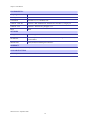
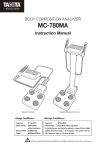
MOTOMESH 1.0.1
Vehicle Mounted
Modem
Users Guide
September 2005
6881011Y54-A
MOTOMESH 1.0.1 Vehicle Mounted Modem Users Guide
This page intentionally left blank.
6881011Y54-A September 2005
ii
MOTOMESH 1.0.1 Vehicle Mounted Modem Users Guide
Copyrights
The Motorola products described in this document may include copyrighted Motorola computer programs. Laws in the United
States and other countries reserve for Motorola certain exclusive rights for copyrighted computer programs. Accordingly, any
copyrighted Motorola computer programs contained in the Motorola products described in this document may not be copied or
reproduced in any manner without the express written permission of Motorola. Furthermore, the purchase of Motorola products
shall not be deemed to grant either directly or by implication, estoppels or otherwise, any license under the copyrights, patents or
patent applications of Motorola, except for the normal nonexclusive, royalty-free license to use that arises by operation of law in
the sale of a product.
Disclaimer
Please note that certain features, facilities and capabilities described in this document may not be applicable to or licensed for use
on a particular system, or may be dependent upon the characteristics of a particular mobile subscriber unit or configuration of
certain parameters. Please refer to your Motorola contact for further information.
Trademarks
Motorola, the Motorola logo, and all other trademarks identified as such herein are trademarks of Motorola, Inc. All other
product or service names are the property of their respective owners.
Copyrights
© 2005 Motorola, Inc. All rights reserved. No part of this document may be reproduced, transmitted, stored in a retrieval system,
or translated into any language or computer language, in any form or by any means, without the prior written permission of
Motorola, Inc.
6881011Y54-A September 2005
iii
MOTOMESH 1.0.1 Vehicle Mounted Modem Users Guide
This page intentionally left blank.
6881011Y54-A September 2005
iv
Table
of
Contents
Contents
. . . . . . . . . . . . . . . . . . . . . . . . . . . . . . . . . . . . . . . . . . . . .
.
.
.
.
Chapter 1:
Introduction........................................................................................... 1-1
The Vehicle Mounted Modem (VMM) Defined................................................................................................... 1-1
VMMs Role within a MOTOMESH Wireless Network .................................................................................. 1-2
Product Contents .............................................................................................................................................. 1-3
Product Specifications...................................................................................................................................... 1-3
Chapter 2:
Device Installation ................................................................................ 2-1
Software Requirements......................................................................................................................................... 2-1
Equipment Requirements...................................................................................................................................... 2-1
MAC Address Label Location ......................................................................................................................... 2-2
MAC Address Tables....................................................................................................................................... 2-3
VMM6300 and VMM7300 Assembly Information.............................................................................................. 2-4
Installing the VMM Device .................................................................................................................................. 2-4
Deployment Considerations ............................................................................................................................. 2-5
Testing the Device Installation ............................................................................................................................. 2-6
Testing Individual Device Components ........................................................................................................... 2-6
Chapter 3:
Device Configuration............................................................................ 3-1
IP Addressing Considerations............................................................................................................................... 3-1
External Device Provisioning from MeshManager............................................................................................... 3-1
Enabling the DHCP Server and Assigning Addresses ..................................................................................... 3-2
Accessing the Device Administration Web Pages ................................................................................................ 3-4
Administrator and User Account Information.................................................................................................. 3-5
Viewing the Device Administration Home Page as an Administrator.................................................................. 3-6
Viewing the Device Administration Home Page as a Normal User................................................................. 3-7
Viewing the VMM Device Administration Configuration Page .......................................................................... 3-8
Device Settings Section.................................................................................................................................... 3-9
Bridge Addressing Section............................................................................................................................... 3-9
Additional Information about the Network DHCP Setting ............................................................................................3-9
Additional Information about the Statically Provisioned Setting................................................................................. 3-10
DHCP Server Section (External Device Provisioning) .................................................................................. 3-10
Security Settings Section (Authentication) .................................................................................................... 3-11
Geo Settings Section ...................................................................................................................................... 3-12
Viewing the VMM Configuration Page as a Normal User ............................................................................ 3-13
6881011Y54-A September 2005
v
MOTOMESH 1.0.1 Vehicle Mounted Modem Users Guide
Chapter 4:
Device Maintenance.............................................................................. 4-1
Changing the Web Interface Password ................................................................................................................. 4-1
Updating the Device Firmware............................................................................................................................. 4-3
Resetting the VMM via the Device Web Page ..................................................................................................... 4-7
Restoring Factory Settings.................................................................................................................................... 4-8
Chapter 5:
Customer Information .......................................................................... 5-1
Customer Service Information.............................................................................................................................. 5-1
Obtaining Support ............................................................................................................................................ 5-1
System Information........................................................................................................................................................5-1
Return Material Request ............................................................................................................................................5-2
Radio Products and Services Division ...........................................................................................................................5-2
Radio Products and Services Division Telephone Numbers.....................................................................................5-2
Returning System Components to Motorola ..................................................................................................................5-2
Returning FREs..............................................................................................................................................................5-2
Chapter 6:
Certification and Safety Information ................................................... 6-1
FCC Regulatory Information ................................................................................................................................ 6-1
FCC RF Radiation Exposure Statement........................................................................................................... 6-1
Safety Information for the MOTOMESH Products .............................................................................................. 6-2
6881011Y54-A September 2005
vi
List
of
Figures
List of Figures
. . . . . . . . . . . . . . . . . . . . . . . . . . . . . . . . . . . . . . . . . . . . .
.
.
.
.
Figure 1-1
Figure 2-1
Figure 2-2
Figure 2-3
Figure 2-4
Figure 3-1
Figure 3-2
Figure 3-3
Figure 3-4
Figure 3-5
Figure 3-6
Figure 3-7
Figure 3-8
Figure 3-9
Figure 4-1
Figure 4-2
Figure 4-3
Figure 4-4
Figure 4-5
Figure 4-6
Figure 4-7
Figure 4-8
Figure 4-9
Figure 4-10
Figure 4-11
Figure 4-12
Figure 4-13
Figure 4-14
Figure 4-15
Figure 4-16
Figure 4-17
Figure 4-18
Figure 4-19
Figure 4-20
Figure 4-21
The VMM Device in Context of the Wireless MOTOMESH Network...............................1-2
VMM Sample Device Label.................................................................................................2-2
VMM External Connection Points .......................................................................................2-4
VMM6300 or VMM7300 Trunk Mounting .........................................................................2-5
VMM Device Information within MeshManager ................................................................2-6
VMM Status .........................................................................................................................3-2
Selecting QDMS Host Configuration...................................................................................3-2
QDMA Host Default Tab .....................................................................................................3-3
QDMA Host Services Tab ...................................................................................................3-3
MOTOMESH Sample Web Interface Login Screen ............................................................3-5
MOTOMESH Device Administration Home Page (Super User Login) ..............................3-6
MOTOMESH Device Administration Home Page (Normal User Login) ...........................3-7
MOTOMESH Device Administration Configuration Page .................................................3-8
VMM Configuration Page (Normal User Account)...........................................................3-13
MOTOMESH Device Administration Home Page ..............................................................4-1
Change Password Page.........................................................................................................4-2
Select Change Admin Password...........................................................................................4-2
Password Change Completed...............................................................................................4-2
Selecting the Update Device Firmware Option....................................................................4-3
Selecting the Browse button on the Firmware Update page ................................................4-4
Selecting the Device Firmware Filename ............................................................................4-4
Selecting Upload Button ......................................................................................................4-5
Confirming the Firmware Filename Selection .....................................................................4-5
Firmware Filename Upload in Progress ..........................................................................4-5
Resetting the Updated Device..........................................................................................4-6
Ready to Reset the Device screen....................................................................................4-6
Device Reset Page – Please stand by…...........................................................................4-6
Resetting the Device ........................................................................................................4-7
Selecting the Update Device Firmware Option ...............................................................4-8
Device Reset Page – Please stand by…...........................................................................4-8
Selecting the Restore Factory Defaults Option................................................................4-9
Restore Factory Settings Page .........................................................................................4-9
Confirm Changes Window for Restore Factory Settings.................................................4-9
Selecting the Update Device Firmware Option .............................................................4-10
Device Reset Page – Please stand by….........................................................................4-10
6881011Y54-A September 2005
vii
List of Figures
This page intentionally left blank.
6881011Y54-A September 2005
viii
List
of
Tables
List of Tables
. . . . . . . . . . . . . . . . . . . . . . . . . . . . . . . . . . . . . . . . . . . . .
.
.
.
.
Table 1-1
Table 2-2
Table 2-3
Table 3-1
Table 3-2
Table 3-3
Table 3-4
Table 3-5
Table 3-6
VMM Product Specification Table ......................................................................................1-3
VMM6300 (2.4) MAC Address Table .................................................................................2-3
VMM7300 (4.9) MAC Address Table .................................................................................2-3
Login Screen Default User Names and Passwords ..............................................................3-5
Device Settings Section (Configuration Tab) ......................................................................3-9
Bridge Addressing Section (Configuration Tab)..................................................................3-9
Device Web Interface - DHCP Server Section (Configuration Tab) .................................3-10
Device Web Interface - Security Settings Section (Configuration Tab) ............................3-11
Device Web Interface - Geo Settings Section (Configuration Tab)...................................3-12
6881011Y54-A September 2005
ix
This page intentionally left blank.
6881011Y54-A September 2005
x
List
of
Procedures
List of Procedures
. . . . . . . . . . . . . . . . . . . . . . . . . . . . . . . . . . . . . . . . . . . . .
.
.
.
.
Procedure 2-1
Procedure 2-2
Procedure 2-3
Procedure 3-1
Procedure 3-2
Procedure 4-1
Procedure 4-2
Procedure 4-3
Procedure 4-4
VMM Hardware Installation Procedure ......................................................................2-4
Testing the VMM Hardware Installation.....................................................................2-6
Additional Testing of the VMM Hardware Installation ..............................................2-6
Enabling the VMM resident DHCP Server .................................................................3-2
Accessing the VMM Device Administration Web Interface.......................................3-4
Changing the Administration Password ......................................................................4-1
Updating the Device Firmware....................................................................................4-3
Resetting the Device Firmware via the Device Web Interface....................................4-7
Restoring the Factory Settings.....................................................................................4-9
6881011Y54-A September 2005
xi
This page intentionally left blank.
6881011Y54-A September 2005
xii
Chapter
1
Chapter 1: Introduction
. . . . . . . . . . . . . . . . . . . . . . . . . . . . . . . . . . . . . . . . . . . . .
.
.
.
.
This guide will assist you with the use, installation, and configuration of the VMM6300 (2.4 GHz) and
the VMM7300 (4.9 GHz), Vehicle Mounted Modem (VMM). Because of the physical and functional
similarities of these two VMMs, the same instructions will apply to both devices except where
specifically noted.
The Vehicle Mounted Modem (VMM) Defined
. . . . . . . . . . . . . . . . . . . . . . . . . . . . . . . . . . . . . . . . . . . . .
.
.
Thank you for purchasing the VMM6300 and/or the VMM7300 Vehicle Mounted Modem. Both
devices are designed to integrate with Motorola’s mesh enabled architecture wireless communication
system capable of supporting high data rate mobile communication at variable rates of vehicular
speeds.
The VMM6300 and the VMM7300 are wireless modems that have been designed for permanent invehicle mounting. Each device provides access to the wireless network via an Ethernet connection to
mobile data terminals, laptop computers, or any other device that has an Ethernet port. The VMM
operates on 12VDC and is rugged enough for installation in commercial and public safety vehicles.
The VMM6300 and the VMM7300 provide the same functionality as the WMC6300 or the WMC7300
(respectively) to the connected device, including geo-location.
The VMM efficiently combines the functionality of a Motorola subscriber device and client modem
into a single cost-effective wireless network component. This makes it easy for any Ethernet-ready
device to access a wireless mobile broadband network. Computers, IP video cameras, sensors, signs,
signals, etc. can all be mesh network enabled to send and receive data at burst rates of up to 6 Mbps.
All standard subscriber device functionality including Multi-Hopping™, non-line-of-sight
communications and geo-location services are fully supported.
The Vehicle Mounted Modem allows connection of multiple IP addressable devices using standard
Ethernet connectivity. This allows devices that cannot accept the PCMCIA based WMC6300 or
WMC7300 product to function transparently on a wireless mesh network without additional drivers.
6881011Y54-A September 2005
1-1
Chapter 1: Introduction
VMMs Role within a MOTOMESH Wireless Network
The VMM is considered a subscriber device (SD) within the MOTOMESH wireless network.
Subscriber devices can communicate with other subscriber devices or with infrastructure devices
(MWRs and IAPs) for wireless network authentication and access. In turn, IAPs act as the principal
network management interface for associated MWRs and SDs.
Figure 1-1
The VMM Device in Context of the Wireless MOTOMESH Network
The VMM device in context of
the MOTOMESH wireless
network.
6881011Y54-A
011Y54-A September 2005
1-2
MOTOMESH 1.0.1 Vehicle Mounted Modem Users Guide
Product Contents
Each mesh-enabled VMM is a full-featured wireless networking device. The following is a list of the
items provided with each VMM:
•
MOTOMESH Vehicle Mounted Modem (flange mount)
•
15 foot cable assembly
•
1 Mag Mount 0 dBi antenna for the 2.4 VMM or the 7dBi antenna for the 4.9 VMM
•
1 N-type to SMA adapter
Product Specifications
The following specifications apply to the VMM6300 (2.4 GHz) and VMM7300 (4.9 GHz) as described
in the table below:
Table 1-1
VMM Product Specification Table
VMM6300 and VMM7300 Physical Specifications
Dimensions
8”x 5.5” x 2”
Weight
1.8 lbs
Packaging
IP54
Std Mounting
Sheet metal screws , not provided
POWER
Power Requirement
5 -15 VDC
Current Drain
1.5 amps
Power Consumption
10W Maximum
Power Cable
12 VDC Power with in-line fuse, Switchcraft EN3C2F connector, Molex 19121009 Spade Lug
RADIO CHARACTERISTICS
(VMM6300) 2.4 motion
(VMM7300) 4.9 motion
Output Power:
24 dBm
24 dBm
Receive Sensitivity:
-85 dB
-85 dB
RF Modulation:
QDMA
QDMA
Operating Freq (GHz):
2.4000-2.4835
4.940-4.990
Tot. Spectrum Used
60MHz
20MHz
Antenna Type (std):
Omni, 0 or 4dBi
Omni, 8dBi
Antenna Connector:
N-Type Female
N-Type
6881011Y54-A September 2005
1-3
Chapter 1: Introduction
ENVIRONMENTAL
Temp range
-35 to 60C
Humidity
0 to 100%
Certification
FCC Part 15, UL, CE Mark, CSA
Vibration – MIL Std
vibration - MIL Standard 810F, Method 514.5 Procedure 1, Category 24
Vibration - TIA
vibration - TIA/EIA-603, paragraph 3.3.4
IP ##
IP54
NETWORK
Management
MeshManager via SNMP
Net Interface
10/100 Mbps Ethernet, RJ45, Sealed Ethernet boot, 3 assignable IP Addresses, no
cord included
Web Interface
Web (HTTP) based management interface
WARRANTY
Standard
1 yr standard
AVALIABLE OPTIONS
Antenna Options
0 Bi omni directional
6881011Y54-A September 2005
1-4
Chapter
2
Chapter 2: Device Installation
. . . . . . . . . . . . . . . . . . . . . . . . . . . . . . . . . . . . . . . . . . . . .
.
.
.
.
Software Requirements
. . . . . . . . . . . . . . . . . . . . . . . . . . . . . . . . . . . . . . . . . . . . .
.
.
There are two ways to install and setup the VMM6300 and the VMM7300 devices: MeshManager or
the MOTOMESH Device Administration web interface.
Between the two available setup methods, MeshManager is the preferred and comprehensive device
setup, configuration, and management application. Prior to using the MeshManager for device
installation and configuration, ensure that it is installed and running on a network computer.
MeshManager will be used during the VMM setup process to validate the installation of the device and
to manage it, (as well as other devices) within the wireless network. It is important to note that a fully
functional mesh network is REQUIRED when using this method.
The MOTOMESH Device Administration web interface can be used to setup and configure the device
by connecting a PC to the wired interface. Please note that the web interface does not offer all the
features that are provided within the MeshManager application. Additional web interface information
is provided later in the manual.
Detailed information about the MeshManager application is found in the MOTOMESH MeshManager
Users Guide.
Equipment Requirements
. . . . . . . . . . . . . . . . . . . . . . . . . . . . . . . . . . . . . . . . . . . . .
.
.
A VMM6300 and a VMM7300 device is utilized similarly to a subscriber device within a Motorola
wireless mesh network and will be used with an IAP (Intelligent Access Point) and a MWR (Mesh
Wireless Modem) Motorola infrastructure devices.
The following list defines the standard hardware components to install a VMM:
•
N-type Antenna Connector
•
Antenna (supplied): 2.4 STD 4dBi, 4.9 STD 8dBi
6881011Y54-A September 2005
2-1
Chapter 2: Device Installation
•
15 foot power cable assembly
The Network Operator must supply the following:
•
Mounting Location
•
Power Source (12V DC) (from vehicle or other DC power supply)
•
A Hub or Switch (if more then 1 Ethernet device will be used)
•
Hand tools for bracket installation
MAC Address Label Location
The transceiver and SBC (Ethernet) MAC addresses for the VMM6300 and for the VMM7300 are
listed on the label located either on the front side or on the back of the VMM unit. Record these
numbers in the MAC Address Tables provided in the next section.
The figure below is only a sample VMM label, an actual device label for either of the VMM devices
will be designated accordingly.
Figure 2-1
VMM Sample Device Label
6881011Y54-A September 2005
2-2
MOTOMESH 1.0.1 Vehicle Mounted Modem Users Guide
MAC Address Tables
Two MAC Address tables have been included for recording the device names and the transceiver and
host MAC addresses for a set of VMM (6300 and 7300 series) devices as a quick reference. These
addresses will be required later in the configuration and management process.
Write the MAC numbers into the MAC Address Tables provided below.
Table 2-2
VMM6300 (2.4) MAC Address Table
VMM Device Name
Table 2-3
2. 4 QDMA XCVR
2. 4 QDMA Host
MAC Address (02-05-12-0A-xx-yy)
MAC Address (00-05-12-0A-xx-yy)
VMM7300 (4.9) MAC Address Table
VMM Device Name
4. 9 XCVR
4.9 Host
MAC Address (02-05-12-0A-xx-yy)
MAC Address (00-05-12-0A-xx-yy)
6881011Y54-A September 2005
2-3
Chapter 2: Device Installation
VMM6300 and VMM7300 Assembly Information
. . . . . . . . . . . . . . . . . . . . . . . . . . . . . . . . . . . . . . . . . . . . .
.
.
The VMM external connection points are shown and labeled in the figure below.
Figure 2-2
VMM External Connection Points
Power
Connector
Power
Reset
N-Type
Antenna
Connector
Ethernet
(Crossover MDI-X)
Installing the VMM Device
. . . . . . . . . . . . . . . . . . . . . . . . . . . . . . . . . . . . . . . . . . . . .
.
.
The following instructions describe the VMM6300 and VMM7300 hardware installation procedure:
Procedure 2-1 VMM Hardware Installation Procedure
1
Mount the VMM device in a suitable location in a vehicle to allow for ventilation.
The device is not waterproof and should be reasonably protected from
moisture and other exposed outdoor environments.
2
Connect the antenna to the N-type connector.
6881011Y54-A
011Y54-A September 2005
2-4
MOTOMESH 1.0.1 Vehicle Mounted Modem Users Guide
3
Insert the Power Plug into Power Connector.
Figure 2-3
VMM6300 or VMM7300 Trunk Mounting
4
Verify that both MAC addresses have been recorded in either Table 2-2 or Table 2-3 of this manual, as
this information will be required to configure and test the device(s).
5
If installing more than one IP device to the VMM6300 or VMM7300, a separate hub device can be
connected to the VMM Ethernet port. The number of devices that can be provisioned to interface with
the VMM depends on the limit of the hub device selected. The VMM device itself has a recommended
limit of 50 devices.
For more information about how to configure additional devices to the
VMM refer to the DHCP Server Section of this manual.
Deployment Considerations
When deploying the VMM consider the following:
•
The antenna should be a minimum of 30 inches from any nearby metal poles to avoid
distortion of the RF pattern.
•
The antenna must have a separation distance of at least 2 meters from the body of all
persons and must not be co-located or operating in conjunction with any other antenna
or transmitter.
•
Users and installers must be provided with antenna installation and transmitter operating
conditions to satisfy RF exposure compliance.
•
Typically, Vehicle Mounted Modems are distributed within a network and are used as
subscriber devices. A rule of thumb is to deploy 2-3 hop networks to optimize range,
latency, and throughput to subscriber devices.
•
The VMM installation location must provide applicable DC power for the device.
•
It is required that the VMM chassis be grounded to minimize the possibility of ESD
(electrostatic discharge) induced damage.
•
Locate the antenna to minimize multipath:
6881011Y54-A September 2005
2-5
Chapter 2: Device Installation
- Minimize interference from nearby transmitters
- Maximize chance of a direct line of sight connection to other devices.
- Mount the supplied antenna vertically
Testing the Device Installation
. . . . . . . . . . . . . . . . . . . . . . . . . . . . . . . . . . . . . . . . . . . . .
.
.
Verify the operation of the VMM using the following procedure (within the network coverage area):
Procedure 2-2 Testing the VMM Hardware Installation
1
Apply power to the VMM. The device will be operational between 60 and 120 seconds.
2
Obtain the Transceiver MAC address and the Host address that was recorded earlier in section Mac
Address Table. The address will be similar to the format 02-05-12-0A-xx-yy for the Transceiver
(XCVR) and 00-05-12-0A-xx-yy for the Host. Please note that the actual MAC addresses will vary from
the samples addresses provided in this guide.
3
Within MeshManager’s DeviceManager screen, right-click on the appropriate VMM in the device tree
and select the Ping Device option.
4
Check for a successful response to the Ping command in the named device results dialog box. A
successful response verifies that the VMM is communicating to the infrastructure devices.
Testing Individual Device Components
You can also choose to ping each of the two individual components located within a VMM: the
Transceiver (XCVR) and the Host.
Procedure 2-3 Additional Testing of the VMM Hardware Installation
1
Apply power to the VMM – the device will be operational in 60 to 120 seconds.
2
Within the MeshManager software screen, double-click on the specific VMM in the device tree.
If MeshManager is able to communicate with the device, the top of the right pane (in MeshManager) will
be updated to show three smaller panes: one general information pane and two component panes (XCVR
and Host, respectively). See the figure shown below.
Figure 2-4
VMM Device Information within MeshManager
6881011Y54-A September 2005
2-6
MOTOMESH 1.0.1 Vehicle Mounted Modem Users Guide
3
From the Select an Action drop-down within the XCVR component pane, select the Ping Component
option.
4
Check for a successful response to the Ping Component option in the named device results dialog box.
A successful response verifies that the VMM is communicating to the infrastructure devices.
5
Repeat the above step for the Host device component.
6
Check for a successful response to the Ping Component option in the named device results dialog box.
6881011Y54-A September 2005
2-7
Chapter 2: Device Installation
This page intentionally left blank.
6881011Y54-A September 2005
2-8
Chapter
3
Chapter 3: Device Configuration
. . . . . . . . . . . . . . . . . . . . . . . . . . . . . . . . . . . . . . . . . . . . .
.
.
.
.
This chapter contains information which will assist you with accessing a VMMs local web interface
and using the available configuration options.
IP Addressing Considerations
. . . . . . . . . . . . . . . . . . . . . . . . . . . . . . . . . . . . . . . . . . . . .
.
.
The VMM provides network access to one or more IP devices connected to the Ethernet port of the
VMM. In order for the VMM to provide service to the IP devices, some configuration must be done
prior to connecting the IP devices.
The local default gateway address is used only on the wired interface, and is only visible to the
attached IP devices. It is not advertised to the wireless network, and the network cannot access the
VMM using this gateway address. The VMM has another IP address for the wireless interface that can
be used to access the VMM from the network. Because the gateway address is limited to the local
wired interface, the same address could be used for the gateway service in several VMM devices. The
local gateway should be a part of the overall subnet chosen for your wireless network.
Care must be taken to ensure that the selected IP address is on the same subnet and does not conflict
with any other devices or the chosen Local Gateway service address on the wireless network.
External Device Provisioning from MeshManager
. . . . . . . . . . . . . . . . . . . . . . . . . . . . . . . . . . . . . . . . . . . . .
.
.
In order for the VMM to provide service to other devices attached to its Ethernet port, some
configuration must be done from MeshManager or the device’s internal web interface.
For additional information about device provisioning options available in the device’s web interface
see the DHCP Server Section (External Device Provisioning) in this manual.
This section will concentrate on performing external device provisioning for the VMM from within
MeshManager’s Device Manager application.
6881011Y54-A September 2005
3-1
Chapter 3: Device Configuration
Enabling the DHCP Server and Assigning Addresses
The following procedure describes how to enable the local DHCP server residing on the VMM and
assign an address range from within MeshManager’s DeviceManager screen.
Procedure 3-1 Enabling the VMM resident DHCP Server
1
Within the MeshManager software screen, double-click on a specific VMM (6300 or 7300 series) in the
device tree.
If MeshManager is able to communicate with the device, the top of the right pane (in MeshManager) will
be updated to show two smaller panes, (one for each of the two main components of the device).
Figure 3-1
2
VMM Status
Within the MeshManager software screen, in the Config 2.4 QDMA Host... section, select the Action
drop-down and choose the Configuration item from the list.
Figure 3-2
Selecting QDMS Host Configuration
6881011Y54-A September 2005
3-2
MOTOMESH 1.0.1 Vehicle Mounted Modem Users Guide
3
From the Config 2.4 QDMA Host… window, select the Services tab.
Figure 3-3
4
On the Services tab, enter the IP address of the network RDATE server into the RDATE Server field.
Figure 3-4
5
QDMA Host Default Tab
QDMA Host Services Tab
Set the Local DHCP Server Enabled field to True.
This will enable the Local DHCP server (resident on the VMM) to allocate IP addresses to devices
attached to the VMM, via hub or other similar device.
When the Local DHCP server is enabled the VMM device will not check for a DHCP server on the wired
network.
6
Provide a DHCP Start IP address.
This is the first IP address in a range of IP addresses that the local DHCP server will allocate to any new
6881011Y54-A September 2005
3-3
Chapter 3: Device Configuration
clients connected to the VMM (with the enabled DHCP server).
The IP address range should reflect the number of clients plus one,
attached to the VMM via hub or other connection. The first IP address
will be used by the DHCP server itself.
7
Provide a DHCP End IP address. This is the last IP address to end the range of addresses begun with the
IP address specified in the DHCP Start IP field.
8
Enter a CIDR value (in bits), reflecting the desired network type.
9
Enter a DHCP Lease Time appropriate for your network.
10
Enter a DHCP Default Suffix.
Depending on the way that your network is setup, this field is optional. The value entered here will be
handed out by the DHCP server and used by client devices for name resolution.
11
Enter a Default Gateway address.
12
Enter a Domain Name Server address, if one exists.
13
Select the Save button to finalize your settings.
Accessing the Device Administration Web Pages
. . . . . . . . . . . . . . . . . . . . . . . . . . . . . . . . . . . . . . . . . . . . .
.
.
The procedure below describes how to access the VMM device web page.
Procedure 3-2 Accessing the VMM Device Administration Web Interface
1
Find the IP address assigned to the VMM SBC prior to accessing the device administration web interface.
You can use MeshManager’s Device Manager to access the VMM SBC IP address. To do this, doubleclick on the VMM in MeshManager’s Device Tree, and then view the resulting SBC IP address
information shown in the right pane.
Note that by default, the device’s addressing mode will be set to Network DHCP.
If a fixed address was provided by the Network Operator in MeshManager, then that
IP address will be used by the VMM instead of the derived address when the
Statically Provisioned option is in effect.
Alternatively, the web page can be accessed by attaching to the device’s Ethernet
port, configured for DHCP.
6881011Y54-A September 2005
3-4
MOTOMESH 1.0.1 Vehicle Mounted Modem Users Guide
2
When the IP address is known, open your web browser and enter the IP address of the VMM SBC.
For example, if the VMM SBC address is 10.128.32.1, then the web page would be found at
http://10.128.32.1/.
If you are running a VMM as a standalone device, the configuration web
page can be reached by connecting a PC to the wired interface. The
installation procedure described here requires administrator access.
Alternatively, all of the parameters that are provisioned via the web page
may also be provisioned via MeshManager.
Administrator and User Account Information
The device has two accounts for the web interface - an Administrative account (Super User), and a
User account (Normal User). The Administrative account must be used for provisioning the device,
and the User account may be used for monitoring the status of the device.
The password for the admin account should be changed during installation. The password for the User
account can be changed by an administrator or the user.
Table 3-1
Login Screen Default User Names and Passwords
Type of User
Username
Password (Default)
Administrator (Super User)
admin
admin
User (Normal User)
monitor
monitor
Figure 3-5
MOTOMESH Sample Web Interface Login Screen
6881011Y54-A September 2005
3-5
Chapter 3: Device Configuration
Viewing the Device Administration Home Page as an
Administrator
. . . . . . . . . . . . . . . . . . . . . . . . . . . . . . . . . . . . . . . . . . . . .
.
.
After the login authentication has been completed, the web browser will display a redirecting page,
and your browser will automatically transition to the home web page for MOTOMESH Device
Administration.
The MOTOMESH Device Administration home page provides you with some basic information about
the device, including the IP addresses assigned to the device, the MAC addresses of the device and the
firmware revision number.
Additional web page links are available when logging-in as an Administrator (same as Super User). In
the Device Management section of the Home tab, the Administrator can:
•
Change Admin password
•
Change User password (Normal User Account)
•
Update Device Firmware
•
Restore Factory Defaults
•
Reset the Device
Figure 3-6
MOTOMESH Device Administration Home Page (Super User Login)
6881011Y54-A September 2005
3-6
MOTOMESH 1.0.1 Vehicle Mounted Modem Users Guide
Viewing the Device Administration Home Page as a Normal
User
The Device Administration home page provides the Normal User (User Account) with some basic
information about the device, including the IP addresses assigned to the device, the MAC addresses of
the device, the firmware revision, and the reported link quality for the link to the IAP.
In the Device Management section of the Home tab, the User Account (non-administrative account)
can:
•
Change User password
•
Reset the Device
Figure 3-7
MOTOMESH Device Administration Home Page (Normal User Login)
6881011Y54-A September 2005
3-7
Chapter 3: Device Configuration
Viewing the VMM Device Administration Configuration
Page
. . . . . . . . . . . . . . . . . . . . . . . . . . . . . . . . . . . . . . . . . . . . .
.
.
Once you have accessed the MOTOMESH Device Administration home page, click on the
Configuration tab to display the IP address configuration.
The MOTOMESH Device Administration Configuration page when viewed as an Administrator (same
as Super User Login) allows for changes to the device configuration.
Figure 3-8
MOTOMESH Device Administration Configuration Page
The following sections describe the main section contents displayed in the Configuration tab of the
device administration web interface.
6881011Y54-A September 2005
3-8
MOTOMESH 1.0.1 Vehicle Mounted Modem Users Guide
Device Settings Section
Table 3-2
Device Settings Section (Configuration Tab)
Field Name
System Name
RDATE Server IP
Address
Field Description
Field Default Value
This is the name of the device as shown by
MeshManager
Assigned by
The IP address of the RDATE server. This is usually the
MiSC when operating in infrastructure mode. The
RDATE server provides the current date to the VMM.
The VMM can operate without an RDATE server.
172.31.0.20
Network Administrator
Bridge Addressing Section
Table 3-3
Bridge Addressing Section (Configuration Tab)
Field Name
Network DHCP
Field Description
Field Default Value
Use this setting to decide whether the device will get its
IP address automatically from a Network DHCP server
or use a fixed address provided manually by a Network
Operator (Statically provisioned).
Network DHCP
IP Address
The IP address will be automatically provided by a
DHCP server if one exists and the above field has been
set to Network DHCP. If the setting has been set as
Statically Provisioned, and not provided by the Network
Operator, then it will be automatically hashed from the
device’s MAC Address.
Varies depending on the
selection made in the
field above.
Subnet Mask
This is the subnet mask for the local Ethernet segment.
blank
Default Gateway
The VMM will tell the attached Ethernet devices to use
this address for the default gateway, and the VMM will
use the address when accessing the local Ethernet
segment.
Assigned by
The address of the local DNS Server.
Assigned by
Or
Statically Provisioned
DNS Server Address
Network Administrator
Network Administrator
DNS Search Suffix
The DNS search suffix provided by the Network
Administrator.
blank
Additional Information about the Network DHCP Setting
Network DHCP means that the VMM device can be configured to request an address from a DHCP
server and requires the inclusion of a DHCP server in the core network configuration to answer these
requests. With Network DHCP selected, the VMM will send DHCP requests for its own address to the
core network once it becomes associated and establishes communications with the infrastructure.
6881011Y54-A September 2005
3-9
Chapter 3: Device Configuration
Operation under the Network DHCP selection allows users to temporarily wander outside of the
network infrastructure without losing connectivity.
The server may be configured by the operator to hand out temporary or static leases. The VMM must
associate and acquire an address from the network before establishing communications. Once a lease
has been granted, the address will be valid out of network coverage for the remainder of the lease or, if
a static lease was granted, until the next power cycle. If the lease expires or the user cycles power
while outside of network coverage, the user will again lose the ability to communicate with the
wireless network.
Additional Information about the Statically Provisioned Setting
When selecting the Statically Provisioned Bridge Addressing option from the Configuration web
page, the VMM device will use provisioned DHCP-like information to establish an IP address for use
in the wireless network. A DHCP server is not required on the core network because the addresses are
derived from the MAC address by default. It should be noted that a DHCP server can still exist on the
network to hand out addresses to other nodes using the Network DHCP option as long as the server's
address range does not conflict with addresses assigned to other devices using the Statically
Provisioned option.
The IP addresses and options used are also configurable per-device using the MOTOMESH
MeshManager application.
The Network Operator can choose to keep the provided (derived IP address) or assign a fixed IP
address and subnet mask. It is up to the Network Operator to ensure that the assigned address is
routable on the core network (if core network access is needed) and that it does not conflict with other
addresses in use. This is analogous to and carries the same caveats as plugging an Ethernet card into a
LAN and manually assigning an address to the card.
DHCP Server Section (External Device Provisioning)
Prior to attaching external devices to the VMM device, the resident DHCP server needs to be enabled.
The current VMM factory defaults automatically enable the DHCP server feature.
Table 3-4
Device Web Interface - DHCP Server Section (Configuration Tab)
Field Name
Field Description
Field Default
Value
Enabled
The VMMs resident DHCP server is enabled when this
checkbox is selected. Use this feature when you need to
attach several devices to the VMMs Ethernet port via a hub or
similar device. The recommended limit is 50 attached
devices.
Check box checked,
feature enabled
DHCP Range Start
This is the first IP address in a range of IP addresses that the
local DHCP server will allocate to any new clients connected
to the VMM (with the enabled DHCP server).
192.168.0.1
6881011Y54-A September 2005
3-10
MOTOMESH 1.0.1 Vehicle Mounted Modem Users Guide
Field Name
Field Description
Field Default
Value
The IP address range must
reflect the number of clients
plus one, attached to the VMM
via hub or other connection. The
first IP address will be used by
the DHCP server itself; this is
why one extra address should be
allocated in the designated IP
address range.
DHCP Range End
This is the last IP address to end the range of addresses begun
with the IP address specified in the DHCP Start IP address
field.
192.168.0.50
CIDR
Enter a CIDR value (in bits), reflecting the desired network
type.
24
DHCP Lease
Duration(s)
This is the duration (in seconds) of the DHCP leases that the
VMM offers to the attached Ethernet devices.
300
Security Settings Section (Authentication)
There are three security authentication settings available to the MOTOMESH VMM device: Force
Authorized, Force Unauthorized, and Local. Security authentication modes are selected from within
the Security Settings section of the MOTOMESH Device Administration Configuration page in the
Authorization Control field
The table below describes each field within the Security Settings section.
Table 3-5
Device Web Interface - Security Settings Section (Configuration Tab)
Field Name
Field Description
Field Default
Value
Authorization
Control
To allow for various levels of security and authentication control, there are
three security authentication settings available to the MOTOMESH VMM
device: Force Authorized, Force Unauthorized, and Local.
Force Authorized
Force Authorized: In Force Authorized mode, there are effectively no
security and authentication controls, resulting in open authentication for all
network devices. There will be no security measures applied to links
between devices that are currently set to Force Authorized. Hardware
authentication via the HAS is still performed but password authentication
is not carried out at the user level and there is no integrity check carried out
for all packets transferred between any source and destination node
Force Unauthorized:
In Force Unauthorized mode, all devices seeking authorization for network
access will be denied, effectively locking down the network. The Force
Unauthorized setting will not allow any network device to establish
communication with any other node that may attempt to communicate with
6881011Y54-A September 2005
3-11
Chapter 3: Device Configuration
Field Name
Field Description
Field Default
Value
the node set to Force Unauthorized.
Local:
In Local mode, the User ID and password for all devices requesting peerto-peer access must be validated against the Group security information
configured in the VMM. If the password is not valid, access will be denied.
If the password is valid, the device will be authorized for peer-to-peer
access and a secure connection will be maintained for the duration of the
association with the Peer communication. Integrity checking will be carried
out on all the packets flowing between the source and destination node.
Local ID
The specified Local ID is used for communication authentication with an
Intelligent Access Point device (IAP).
LOCAL
Local
Password
The password used for authentication control between a local subscriber
device and an IAP device.
1234
Group ID
The specified Group ID is used for authentication control between local
subscriber devices when communicating in peer-to-peer mode.
GROUP
Group
Password
The password used between local subscriber devices that belong to the
same assigned group and share the same password.
1234
Geo Settings Section
Table 3-6
Device Web Interface - Geo Settings Section (Configuration Tab)
Field Name
Field Description
Field Default Value
Enable Geo Position
Selecting this checkbox enables the reporting of the
device’s physical location in Geo coordinates.
Checkbox Disabled
Reporting Interval
This value represents how often the devices position is
relayed to the Primary and secondary (if IP address
provided) MAP server.
0
Primary MAP server
The IP address of the Primary (main) MAP Server where
the Geo location coordinates are to be sent. The address
may be provided by a Network Administrator or user
running the MOTOMESH MeshView application.
0
Secondary MAP
server
The IP address of the Secondary (additional) MAP Server
or workstation where the Geo location coordinates are to
be sent. The address may be provided by a Network
Administrator or user running the MOTOMESH
MeshView application.
0
6881011Y54-A September 2005
3-12
MOTOMESH 1.0.1 Vehicle Mounted Modem Users Guide
Viewing the VMM Configuration Page as a Normal User
When a Normal User logs into the Device Administration web interface, the Configuration page
contents will be the same as when viewed by an administrator account. The only difference is that
Normal users can ONLY change the User Password and Reset the device.
Figure 3-9
VMM Configuration Page (Normal User Account)
6881011Y54-A September 2005
3-13
Chapter 3: Device Configuration
This page intentionally left blank.
6881011Y54-A September 2005
3-14
Chapter
4
Chapter 4: Device Maintenance
. . . . . . . . . . . . . . . . . . . . . . . . . . . . . . . . . . . . . . . . . . . . .
.
.
.
.
This chapter describes the available device maintenance functions through the use of the device’s local
web interface.
Changing the Web Interface Password
. . . . . . . . . . . . . . . . . . . . . . . . . . . . . . . . . . . . . . . . . . . . .
.
.
For security reasons it is important to change the Administration password at your earliest
convenience. The Change Admin Password and the Change User Password options are available on
the MOTOMESH Device Administration Home Page.
Procedure 4-1 Changing the Administration Password
1
Select the Change Admin Password option from the MOTOMESH Device Administration Home Page.
Figure 4-1
2
MOTOMESH Device Administration Home Page
Enter your new administrator password twice (on the Change Password page) and select Submit.
6881011Y54-A September 2005
4-1
Chapter 4: Device Maintenance
Figure 4-2
3
Enter the newly changed password on the MOTOMESH Web Interface Login screen.
Figure 4-3
4
Change Password Page
Select Change Admin Password
Select the Finished button to return to the MOTOMESH Device Administration home page.
Figure 4-4
Password Change Completed
6881011Y54-A September 2005
4-2
MOTOMESH 1.0.1 Vehicle Mounted Modem Users Guide
Updating the Device Firmware
. . . . . . . . . . . . . . . . . . . . . . . . . . . . . . . . . . . . . . . . . . . . .
.
.
The web interface for the device also provides the ability to update the firmware on-site. To use this
feature, you must have a SBC (Host) firmware update file from a released upgrade package.
Please note that ONLY the SBC device component can be upgraded via the web
interface at this time. Use MeshManager’s Upgrade Tool to upgrade the
Transceiver, the 802.11 AP, as well as the SBC device components. See the
MOTOMESH Field Upgrade Procedure Guide for detail information about
updating device components via MeshManager’s Upgrade Tool.
Procedure 4-2 Updating the Device Firmware
1
Select the Update Device Firmware option from the MOTOMESH Device Administration home page.
Figure 4-5
Selecting the Update Device Firmware Option
6881011Y54-A September 2005
4-3
Chapter 4: Device Maintenance
2
Select the Browse button on the Firmware Update page.
Figure 4-6
3
Selecting the Browse button on the Firmware Update page
Browse to the firmware file location on your network and then select the appropriate device name. For
the VMM device the SBC firmware file name will be in the format of m-kru-mea_memmem_sbc_x.x.x.x.tar.
Please note that ONLY the SBC device component can be upgraded via
the web interface at this time. Use MeshManager’s Upgrade Tool to
upgrade the Transceiver, the 802.11 AP, as well as the SBC device
components. See the MOTOMESH Field Upgrade Procedure Guide
for information about updating devices via the Upgrade Tool.
Figure 4-7
Selecting the Device Firmware Filename
6881011Y54-A September 2005
4-4
MOTOMESH 1.0.1 Vehicle Mounted Modem Users Guide
4
Select the Upload button after selecting the correct device firmware filename.
Figure 4-8
5
Select the OK button to confirm your firmware filename selection.
Figure 4-9
6
Selecting Upload Button
Confirming the Firmware Filename Selection
After the firmware filename selection has been confirmed, the web browser will transmit the file to the
device, and the device will present a Please stand by while the device is uploading… screen.
Select the Close button from the bottom of this page.
Figure 4-10
Firmware Filename Upload in Progress
6881011Y54-A September 2005
4-5
Chapter 4: Device Maintenance
7
Re-open the web interface for the device updated in the previous step, and select Reset the Device option
from the Home page. The device must be reset before the updated firmware version name will be
reflected on the Home page.
Figure 4-11
8
Select the Reset button to initiate the reset process.
Figure 4-12
9
Resetting the Updated Device
Ready to Reset the Device screen
Standby for up to 120 seconds for the device to reset.
Figure 4-13
Device Reset Page – Please stand by…
6881011Y54-A September 2005
4-6
MOTOMESH 1.0.1 Vehicle Mounted Modem Users Guide
10
When the device has completed the reset process, the web interface will automatically return to the
MOTOMESH Device Administration Home page. Check that the Home page reflects the updated
firmware name and version.
NOTE: After the completion of the reset, you may experience a slight delay when bringing up another
web page - be patient.
11
End of Procedure.
Resetting the VMM via the Device Web Page
. . . . . . . . . . . . . . . . . . . . . . . . . . . . . . . . . . . . . . . . . . . . .
.
.
The device can be reset via the device administration web interface as well as MeshManager’s Device
Manager.
In order to reset the device via the web page, follow the procedure outlined below.
Procedure 4-3 Resetting the Device Firmware via the Device Web Interface
1
Select the Reset the Device option from the MOTOMESH Device Administration home page.
Figure 4-14
Resetting the Device
6881011Y54-A September 2005
4-7
Chapter 4: Device Maintenance
2
Select the Reset button to initiate the reset process.
Figure 4-15
3
Standby for up to 120 seconds for the device to reset.
Figure 4-16
4
Selecting the Update Device Firmware Option
Device Reset Page – Please stand by…
When the device has completed the reset process, it will automatically display the MOTOMESH Device
Administration home page.
NOTE: After the completion of the reset, you may experience a slight delay when bringing up another
web page. Be patient.
Restoring Factory Settings
. . . . . . . . . . . . . . . . . . . . . . . . . . . . . . . . . . . . . . . . . . . . .
.
.
To restore the factory settings in your VMM device, the Restore Factory Defaults option is available
from the MOTOMESH Device Administration home page.
The Restore Factory Settings operation will restore the default web password for the administrator and
monitor accounts. This will also return the local IP addresses to use the Network DHCP addressing
scheme.
6881011Y54-A September 2005
4-8
MOTOMESH 1.0.1 Vehicle Mounted Modem Users Guide
The device’s addressing scheme will be set to use Network DHCP addressing
after the Factory Defaults are restored.
Procedure 4-4 Restoring the Factory Settings
1
Select the Restore Factory Defaults option from the MOTOMESH Device Administration home page.
Figure 4-17
2
Select the Apply button to initiate restoring the factory settings process.
Figure 4-18
3
Selecting the Restore Factory Defaults Option
Restore Factory Settings Page
Select the OK button in the confirmation dialog to proceed restoring the device, or press Cancel to stop.
Figure 4-19
Confirm Changes Window for Restore Factory Settings
6881011Y54-A September 2005
4-9
Chapter 4: Device Maintenance
4
Select the Finished button to be automatically redirected to the Device Reset screen.
5
Select the Reset button from the Device Reset page to initiate the reset process.
Figure 4-20
6
Standby for up to 120 seconds for the device to reset.
Figure 4-21
7
Selecting the Update Device Firmware Option
Device Reset Page – Please stand by…
When the device has completed the reset process, it will automatically display the MOTOMESH Device
Administration home page.
NOTE: After the completion of the reset, you may experience a slight delay when bringing up another
web page. Be patient.
6881011Y54-A September 2005
4-10
Chapter
5
Chapter 5: Customer Information
. . . . . . . . . . . . . . . . . . . . . . . . . . . . . . . . . . . . . . . . . . . . .
.
.
.
.
This chapter provides information about how to obtain customer service support from Motorola and
describes the type of information you should have available prior to making the support call.
Customer Service Information
. . . . . . . . . . . . . . . . . . . . . . . . . . . . . . . . . . . . . . . . . . . . .
.
.
If you have read this document and made every effort to resolve installation or operation issues
yourself and still require help, please contact Motorola System Support Center (SSC) using the
following contact information:
Hours of Operation
7 days a week, 24 hours
Technical Support:
800-221-7144 (USA)
Obtaining Support
Motorola provides technical support services for your system and recommends that you coordinate
warranty and repair activities through the Motorola System Support Center (SSC). When you consult
the Motorola SSC, you increase the likelihood that problems are rectified in a timely fashion and that
warranty requirements are satisfied. Check your contract for specific warranty and service information.
System Information
To be provided with the best possible opportunity for support, collect the following system information
and have it available when obtaining support.
•
Location of the system
•
Date the system was put into service
•
Software or firmware version information for components of your system
6881011Y54-A September 2005
5-1
Chapter 5: Customer Information
•
Serial number(s) of the device(s) or component(s) requiring support
•
A written description of the symptom or observation of the problem:
- When did it first appear?
- Can it be reproduced?
- What is the step-by-step procedure to cause it?
•
Do other circumstances contribute to the problem? For example, changes in weather or
other conditions?
•
Maintenance action preceding problem:
- Upgrade of software or equipment
- Change in the hardware or software configuration
- Software reload - from backup or from CD-ROM (note the version and date)
Return Material Request
After collecting system information, contact the Motorola System Support Center for assistance or to
obtain a Return Material Authorization (RMA) number for faulty Field Replaceable Entities (FREs):
North America: 800-221-7144
Radio Products and Services Division
The Radio Products and Services Division is your source for manuals and replacement parts.
Radio Products and Services Division Telephone Numbers
The telephone numbers for ordering are: (800)-422-4210 (US and Canada orders)
The fax numbers are: (800)-622–6210 (US and Canada orders)
The number for help identifying an item or part number is (800)-422-4210; select choice “3” from the
menu
Returning System Components to Motorola
Motorola's service philosophy is based on field replaceable entities (FREs). FREs are system
components identified by Motorola to be returned to Motorola for repair. In turn, Motorola sends you a
replacement FRE component to help you maintain maximum operating performance for your system.
Returning FREs
Return faulty FREs to Motorola for repair. When you return an assembly for service, follow these best
practices:
•
Place any assembly containing CMOS devices in a static-proof bag or container for
shipment.
•
Obtain a return authorization (RA) number from the Motorola System Support Center.
6881011Y54-A September 2005
5-2
MOTOMESH 1.0.1 Vehicle Mounted Modem Users Guide
•
Include the warranty, model, kit numbers, and serial numbers on the job ticket, as
necessary.
•
If the warranty is out of date, you must have a purchase order.
•
Print the return address clearly, in block letters.
•
Provide a phone number where your repair technician can be reached.
•
Include the contact person's name for return.
•
Pack the assembly tightly and securely, preferably in its original shipping container.
6881011Y54-A September 2005
5-3
Chapter 5: Customer Information
This page intentionally left blank.
6881011Y54-A September 2005
5-4
Chapter
6
Chapter 6: Certification and Safety
Information
. . . . . . . . . . . . . . . . . . . . . . . . . . . . . . . . . . . . . . . . . . . . .
.
.
.
.
This chapter lists the relevant FCC Certification and Product Safety Information for the MOTOMESH
devices described in this manual.
FCC Regulatory Information
This device complies with Part 15 of the FCC Rules. Operation is subject to the following two
conditions: (1) this device may not cause harmful interference, and (2) this device must accept any
interference received; including interference that may cause undesired operation.
The VMM6300 and the VMM7300 requires professional installation to ensure the installation is
performed in accordance with FCC licensing regulations.
Federal Communications Commission (FCC) Statement:
This equipment has been tested and found to comply with the limits for a Class A digital device,
pursuant to part 15 of the FCC Rules. These limits are designed to provide reasonable protection
against harmful interference when the equipment is operated in a commercial environment. This
equipment generates, uses, and can radiate radio frequency energy and, if not installed and used in
accordance with the instruction manual, may cause harmful interference to radio communications.
Operation of this equipment in a residential area is likely to cause harmful interference in which case
the user will be required to correct the interference at his own expense.
Any changes or modifications not expressly approved by Motorola could void the user’s authority to
operate the equipment.
FCC RF Radiation Exposure Statement
This equipment complies with FCC radiation exposure limits set forth for an uncontrolled
environment. This equipment should be installed and operated with a minimum distance of 2 meters
between the radiator and your body.
6881011Y54-A September 2005
6-1
Chapter 6: Certification and Safety Information
Safety Information for the MOTOMESH Products
The Federal Communications Commission (FCC) with its action in ET Docket 96-8 has adopted a
safety standard for human exposure to radio frequency (RF) electromagnetic energy emitted by FCC
certified equipment. Motorola MOTOMESH products meet the uncontrolled environmental limits
found in OET-65 and ANSI C95.1, 1991. Proper operation of this radio according to the instructions
found in this manual and the hardware and software guides on the MOTOMESH CD will result in user
exposure that is substantially below the FCC recommended limits.
•
Do not touch or move the antenna(s) while the unit is transmitting or receiving.
•
Do not hold any component containing a radio such that the antenna is very close to or
touching any exposed parts of the body, especially the face or eyes, while transmitting.
•
Do not operate a portable transmitter near unshielded blasting caps or in an explosive
environment unless it is a type especially qualified for such use.
•
Do not operate the radio or attempt to transmit data unless the antenna is connected;
otherwise, the radio may be damaged.
Conforms to UL STD ANSI/UL 60950 3rd Edition
Certified to CAN/CSA C22.2 NO. 60950-00
Equipment shall be suitable for use in Air pressure: 86kPa to106kPa.
6881011Y54-A September 2005
6-2
Index
Index
. . . . . . . . . . . . . . . . . . . . . . . . . . . . . . . . . . . . . . . . . . . . .
.
.
.
.
Local Gateway service address, 3-1
A
M
antenna, 1-3, 2-4, 2-5, 2-6, 6-2
Antenna, 1-3, 1-4, 2-1
MAC addresses, 2-2, 2-3, 2-5, 3-6, 3-7
MOTOMESH Device Administration home page, 4-7
Mounting Location, 2-2
B
bracket, 2-2
P
C
Ping Component option, 2-7
Power Source, 2-2
Provisioning
External Devices, 3-1
cable assembly, 1-3, 2-2
CIDR value (in bits), 3-4, 3-11
Copyrights, iii
R
D
RDATE Server, 3-3, 3-9
Reset button, 4-6
RF exposure, 2-5
DC power, 2-5
Default Gateway address, 3-4
DHCP Default Suffix, 3-4
DHCP End IP address, 3-4
DHCP Lease Time, 3-4
DHCP server, 3-3, 3-4, 3-9, 3-10
DHCP Start IP address, 3-3
Disclaimer, iii
DNS server, 3-4
Domain Name Server address, 3-4
S
SBC, 2-2, 3-5, 6-1
Services tab, 3-3
subnet, 3-1, 3-9, 3-10
subscriber, iii, 1-1, 2-1, 2-5
devices, 2-5
Switch, 2-2
H
T
hardware installation, 2-4
host, 2-3, 2-6
hub, 2-5, 3-3, 3-10
Hub, 2-2
Trademarks, iii
transceiver, 2-2, 2-3, 2-6
V
I
VMM, 2-3, 3-5, 6-1
internal web interface, 3-1
IP address, 3-1
W
L
web interface, 3-1, 4-6
local DHCP server, 3-2
Local DHCP Server Enabled field, 3-3
6881011Y54-A September 2005
Index-1
Index
This page intentionally left blank
6881011Y54-A September 2005
Index -2
Glossary
Glossary
. . . . . . . . . . . . . . . . . . . . . . . . . . . . . . . . . . . . . . . . . . . . .
.
.
.
CIDR – Classless Inter-Domain Routing (A new Internet addressing scheme replacing
the old A, B, C addressing scheme)
IAP – Intelligent Access Point
MEA – Mesh Enabled Architecture
MiSC – Mobile Internet Switching Controller
MWR – Mesh Wireless Router sometimes referred to as a Wireless Router (WR)
SBC – Single Board Computer
SD – Subscriber Device, a general description to a device type that is usually a WMC or
a VMM.
VMM– Vehicle Mounted Modem
WMC – Wireless Modem Card, can apply to any model number
6881011Y54-A September 2005
Glossary-1
Glossary
This page intentionally left blank
6881011Y54-A September 2005
Glossary-2