1
eView MT5000/MT4000 Series Touch Screen User Manual
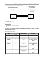
Contents
PREFACE...................................................................................................................................................... 4
CHAPTER 1
INSTALLATION OF EV5000............................................................................................ 7
1.1 INSTALLING EV5000 ............................................................................................................................ 7
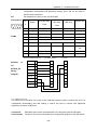
1.2 INTERFACE DIAGRAM............................................................................................................................ 9
CHAPTER 2
CREATING A SIMPLE PROJECT ................................................................................ 14
2.1 NEW AN EMPTY PROJECT ................................................................................................................... 14
2.2 ADDING A SWITCH COMPONENT ........................................................................................................ 20
CHAPTER 3
DESCRIPTION OF THE EV5000 SOFTWARE .......................................................... 26
3.1 USER INTERFACE OF EV5000 ........................................................................................................... 26
3.2 GRAPH ELEMENT WINDOW ................................................................................................................ 58
3.3 PROJECT FILE WINDOW ..................................................................................................................... 62
3.4 PROJECT WINDOW AND PROJECT CONSTRUCT WINDOW:............................................................... 63
3.5 COMPILE INFORMATION WINDOW ...................................................................................................... 65
3.6 COMPONENT LIST WINDOW ............................................................................................................... 66
3.7 OFFLINE SIMULATION ......................................................................................................................... 66
3.8 ONLINE SIMULATION ........................................................................................................................... 67
3.9 DOWNLOAD ......................................................................................................................................... 69
CHAPTER 4
CONFIGURATION WINDOWS...................................................................................... 87
4.1 WINDOW TYPE .................................................................................................................................... 87
4.2 WINDOW PROPERTIES ....................................................................................................................... 90
4.3 CREATING A WINDOW ......................................................................................................................... 93
4.4 OPENING A WINDOW .......................................................................................................................... 93
4.5 DELETING A WINDOW ......................................................................................................................... 94
4.6 EXAMPLES FOR WINDOWS ................................................................................................................. 94
4.7 WINDOW-RELATED COMPONENTS ................................................................................................... 104
CHAPTER 5
DESIGN WITH EV5000, SOME BASIC KNOWLEDGE.......................................... 105
5.1 PARTS ............................................................................................................................................... 105
5.2 ABOUT PART ID ................................................................................................................................ 106
5.3 ADDITIONAL NOTE (DESCRIPTION) .................................................................................................. 107
5.4 INPUT/OUTPUT ADDRESS OF PLC................................................................................................... 108
5.5 VECTOR GRAPH ................................................................................................................................ 109
5.6 BITMAP GRAPHICS............................................................................................................................ 116
5.7 CREATING A LABEL ........................................................................................................................... 121
5.8 TASKBAR AND TASK BUTTONS ......................................................................................................... 122
CHAPTER 6
COMPONENTS(PARTS).............................................................................................. 125
6.1 INDICATOR LAMP............................................................................................................................... 126
6.2 BIT SETTING COMPONENT ............................................................................................................... 130
6.3 SWITCH ............................................................................................................................................. 133
6.4 WORD SETTING ................................................................................................................................ 134
6.5 MULTI-STATE DISPLAY ...................................................................................................................... 137
6.6 MULTI-STATE SWITCH ...................................................................................................................... 139
6.7 XY PLOT ........................................................................................................................................... 141
6.8 MOVING COMPONENT ...................................................................................................................... 144
6.9 ANIMATION ........................................................................................................................................ 148
6.10 NUMBER INPUT ............................................................................................................................... 152
6.11 NUMERIC DISPLAY .......................................................................................................................... 158
6.12 TEXT INPUT ..................................................................................................................................... 160
6.13 TEXT DISPLAY ................................................................................................................................. 168
6.14 BAR GRAPH .................................................................................................................................... 169
6.15 METER ............................................................................................................................................ 172
1
eView MT5000/MT4000 Series Touch Screen User Manual
Contents
6.16 INDIRECT WINDOW ......................................................................................................................... 174
6.17 DIRECT WINDOW ............................................................................................................................ 178
6.18 ALARM INFORMATION LOGON ........................................................................................................ 179
6.19 ALARM DISPLAY .............................................................................................................................. 181
6.20 TREND CURVE ................................................................................................................................ 183
6.21 RECIPE DATA .................................................................................................................................. 196
6.22 EVENT ENTRY (EVENT INFORMATION LOGON).............................................................................. 196
6.23 EVENT DISPLAY .............................................................................................................................. 200
6.24 ALARM BAR..................................................................................................................................... 207
6.25 OSCILLOSCOPE .............................................................................................................................. 210
6.26 SCALE ............................................................................................................................................. 214
6.27 SCROLL BAR ................................................................................................................................... 215
6.28 MESSAGE BOARD (NOTE PAD)...................................................................................................... 218
6.29 FUNCTION KEY ............................................................................................................................... 223
6.30 TIMER.............................................................................................................................................. 233
6.31 VIDEO COMPONENTS (ONLY APPLICABLE TO MT5600T/MT5700T) .......................................... 239
6.32 BITMAP COMPONENT ..................................................................................................................... 244
6.33 VECTOGRAM COMPONENT ............................................................................................................ 245
6.34 TEXT LIBRARY ................................................................................................................................ 245
6.35 ADDRESS TAG .............................................................................................................................. 248
6.36 PLC CONTROL ............................................................................................................................... 251
6.37 ABOUT OVERLAPPING OF COMPONENTS ...................................................................................... 256
CHAPTER 7
7.1
7.2
7.3
7.4
7.5
7.6
SYSTEM PARAMETERS ............................................................................................. 262
HMI................................................................................................................................................. 262
TASKBAR ......................................................................................................................................... 263
HMI EXTEND ATTRIBUTIONS .......................................................................................................... 265
PRINT SETTINGS ............................................................................................................................ 268
COM SETTINGS ............................................................................................................................. 269
PLC STATION NO. .......................................................................................................................... 271
CHAPTER 8
RECIPE DATA................................................................................................................ 273
8.1 CREATING A RECIPE DATA TRANSMISSION COMPONENT ............................................................. 273
8.2 RECIPE MEMORY ........................................................................................................................... 274
8.3 UPLOADING/DOWNLOADING OF RECIPE DATA BETWEEN TOUCH SCREEN AND PLC ................. 281
CHAPTER 9
MACRO CODE .............................................................................................................. 290
9.1 GETTING STARTED: A SIMPLE MACRO TEMPLATE ........................................................................... 290
9.2 OPERATING PRINCIPLES OF MACRO TEMPLATE AD READ/WRITE VARIABLE............................... 295
9.3 TRIGGERING OF MACRO ................................................................................................................ 297
9.4 EXAMPLES ...................................................................................................................................... 298
CHAPTER 10
PRINT ............................................................................................................................ 305
10.1 FUNCTION KEY ............................................................................................................................... 305
10.2 SCREEN PRINTOUT ........................................................................................................................ 306
10.3 REPORT OUTPUT ........................................................................................................................... 307
10.4 EVENT PRINTOUT ........................................................................................................................... 308
10.5 PRINTING FAILURE ......................................................................................................................... 309
CHAPTER 11 RESERVED REGISTER ADDRESSES OF THE SYSTEM..................................... 311
11.1 LOCAL BIT (LB) REGISTERS RESERVED ......................................................................................... 311
11.2 LOCAL WORD (LW) REGISTERS RESERVED .................................................................................. 316
11.3 NONVOLATILE LOCAL WORD (LW10000~10256) ........................................................................ 318
CHAPTER 12
SECURITY LEVEL ...................................................................................................... 321
CHAPTER 13
SERIAL COMMUNICATION...................................................................................... 335
13.1 SERIAL COMMUNICATION ............................................................................................................... 335
2
eView MT5000/MT4000 Series Touch Screen User Manual
Contents
13.2 RS-232........................................................................................................................................... 336
13.3 RS-422........................................................................................................................................... 338
13.4 RS-485........................................................................................................................................... 340
CHAPTER 14
CONNECTION OF EVIEW MT5000/4000 WITH COMMON PLCS .................... 343
14.1 OMRON PLC ................................................................................................................................ 343
14.2 MITSUBISHI PLC ............................................................................................................................ 353
14.3 KOYO PLC .................................................................................................................................... 362
14.4 ALLEN-BRADLEY PLC .................................................................................................................... 369
14.5 MODICON PLC ............................................................................................................................ 374
14.6 FACON PLC.................................................................................................................................. 378
14.7 SIEMENS PLC.............................................................................................................................. 381
14.8 LG PLC .......................................................................................................................................... 386
14.9 MATSUSHITA PLC........................................................................................................................... 391
14.10 DELTA PLC ................................................................................................................................. 394
14.11 MODBUS RTU CONTROLLER .................................................................................................... 396
14.12 MODBUS ASCII CONTROLLER .................................................................................................. 398
14.13 VIGOR PLC ................................................................................................................................ 401
14.14 EMERSON PLC ......................................................................................................................... 403
14.15 KEYENCE PLC ...................................................................................................................... 405
14.16 OEMAX PLC ............................................................................................................................ 408
14.17 ABB (07KR51) PLC ................................................................................................................... 410
14.18 EVIEW MASTER AND EVIEW SLAVE (MASTER/SLAVE PROTOCOL CONNECTION) ................... 412
14.19 BAUMULLER CONTROLLER ...................................................................................................... 413
14.20 KINCO ECOSTEP CONTROLLER ........................................................................................... 414
CHAPTER 15
OPERATION INSTRUCTIONS FOR EVMANAGER ............................................. 417
15.1 INTRODUCTION TO EVMANAGER ................................................................................................... 417
15.2 DOWNLOAD OPERATE.................................................................................................................. 418
15.3 UPLOAD OPERATE.......................................................................................................................... 424
15.4 SYSTEM OPERATE .......................................................................................................................... 427
CHAPTER 16
USE OF SETUP........................................................................................................... 430
CHAPTER 17
NETWORKING OF MT5000 SERIES TOUCH SCREENS................................. 432
17.1 NETWORKING ................................................................................................................................. 432
17.2 MUTUAL DOWNLOAD BETWEEN DIFFERENT TOUCH SCREENS ................................................. 445
APPENDIX I
SYSTEM MESSAGES .................................................................................................. 446
MT5000/4000 SYSTEM MESSAGES TABLE ........................................................................................... 446
APPENDIX II
TROUBLESHOOTING................................................................................................. 447
APPENDIX III
HARDWARE OVERVIEW .......................................................................................... 450
INSTALLATION OF MT5000 SERIES TOUCH SCREENS .......................................................................... 450
1. INSTALLATION OVERVIEW ................................................................................................................... 450
2. INSTALLATION INSTRUCTIONS............................................................................................................. 450
3. PROGRAMMING SOFTWARE ............................................................................................................... 459
4. PRODUCT SPECIFICATIONS ................................................................................................................ 460
3
eView MT5000/MT4000 Series Touch Screen User Manual
Preface
Preface
Thank you for buying MT5000 and MT4000 series industrial embedded Human-Machine Interface
(hereinafter referred to as “HMI”) products.
HMI is a two-way communication bridge between an operator and a machine. A user can combine
characters, buttons, figures and numerals to process or monitor, manage and deal with the
multifunctional display screen which may display ever-changing information anytime. With the
rapid development of the mechanical equipment, old operation interfaces can only be operated by
skilled service-trained professionals, and furthermore, the operation is difficult and the working
efficiency can not be improved. However, the application of the HMI can make clear indication and
inform the operator of the current conditions of the machine so that the operation will be simple
and visual, misoperations can be reduced, and even a new operator can operate the entire
machine easily. Furthermore, the use of the HMI can also implement standard and simple cabling
of a machine, and meanwhile the number of I/O points necessary for the PLC (Programmable
Logic Controller) can be reduced, and the added value of the entire set of equipment can be
relatively improved due to the compact size and high performance of the control panel at the same
time when the production cost is reduced.
As a new kind of HMI, touch screen has attracted wide attention since its emergence. With its
simplicity, operational convenience, powerful function and excellent stability, it is applicable to
industrial environments, and even can find wide application in our daily life. For example,
automatic parking equipment, automatic car washer, roller-bridge lifting and hoisting control,
production line monitoring & control, or even intelligent building management, conference room
audible/visual control, and temperature adjustment.
With the rapid development of the science and technology, more and more machines and field
operations need the use of HMIs. The powerful function of PLC and the complicated data
processing also call for the emergence of a convenient matching HMI. The development of touch
screen is undoubtedly a great innovation in the automation field in the 21st century.
MT5000 and MT4000 are a brand-new generation of industrial embedded touch screen HMIs, with
the following features:
– Embedded RISC CPU featuring high speed and low power consumption
– Embedded operating system
– Higher speed and more smooth operation
– Richer color and finer display
– The MT5000 fully supports such high-speed interfaces as the Ethernet and USB
interfaces, and the MT4000 supports high-speed USB interfaces.
– More resources, and lower price
4
eView MT5000/MT4000 Series Touch Screen User Manual
Preface
– Simple, easy to use, stable and reliable.
The MT5000 and MT4000 series HMIs have the following new features:
• The 65536-color display mode gives richer color to the touch screen, with incomparable
display effect.
• With the application of powerful 200 ~ 400 MHz 32-bit RISC processor, the MT5000 and
MT4000 have higher processing speed.
• The product supports simultaneous communications of multiple serial ports. The two
serial ports of the standard hardware can use different protocols to connect different
controllers at the same time.
• The MT5000 completely supports the Ethernet communications function, and multiple
touch screens can be networked at will.
• The function of image file support is added, supporting the import of images in such
formats as 24-bit bitmap, JPEG and GIF.
• Standard C-language macrocodes can be triggered in multiple modes, featuring
powerful function, high flexibility and easy operation.
• Powerful timer function
• USB download greatly accelerates the download speed in user configuration.
• The communication capability of the USB ports is increased, so that programs can be
downloaded through the USB ports.
• SPC (Stored Programmable Controlled) contrast and brightness: The contrast and
brightness are adjusted through the Local Bit (LB).
• User-defined start interface: The user can customize a start LOGO interface.
• Supporting all fonts of the Windows platform;
• Supporting the drawing of any arcs and sector diagrams;
• Supporting direct connection with most mainstream PLCs, the MT5000 and MT4000 will
have wider market and application prospect.
• With the simple, convenient and powerful EV5000 configuration software, the user can
master its design method and design first-class works at the fastest speed.
Before using the MT5000 and MT4000 series touch screens, please read this manual carefully to
ensure correct operation of the equipment and the safety of the user and equipment so that the
touch screens can achieve the best operation effect. In the meantime, please keep the manual
well for future references in commissioning, maintenance, examination and repair. If you have any
doubts or problems during the use of the product, please feel free to contact the Technical Support
Department of our company without delay.
Our product will surely better meet your requirements, and the application of our product will boost
your business career. Any suggestions and comments on our products are welcome. If you have
5
eView MT5000/MT4000 Series Touch Screen User Manual
Preface
any suggestions, comments or complaints on our product, please contact us immediately at any
time (we provide 7 days * 24 hours service), and we will make quick and satisfactory response as
soon as possible.
The following sections present a detailed description of our product.
6
Chapter 1
Chapter 1
Installation of EV5000
Installation of EV5000
1.1 Installing EV5000
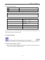
z
Minimum Computer Hardware Requirement (Recommended Configuration):
CPU: INTEL Pentium II or better
Memory: 128 MB or higher (512 MB is recommended)
Hard disk: 2.5 GB or above, at least a free disk space over 100 MB (40G or above is
recommended)
CD ROM: One 4X CD-ROM optical drive
Monitor: Supporting monitor with a resolution of 800*600, and 16-bit color or above
(recommended: 1024×768, 32-bit true color or above)
Mouse and keypad: One for each
RS-232 COM port: At least one port available for serial communications between PC and the
touch panel
USB port: USB A-type port (1.1 or 2.0)
z
Operating system:
Windows 2000 (with SP4)/ Windows XP (with SP2)
z
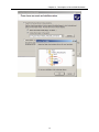
Installation procedure:
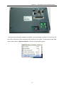
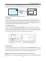
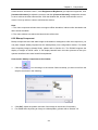
1
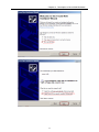
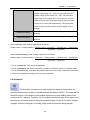
After Inserting the EV5000 setup disk into the optical drive, the setup program will
automatically run, or you may manually run the Setup.exe file under the root directory of the
CD.
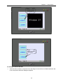
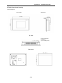
The following interface appears:
7
Chapter 1
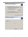
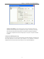
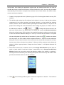
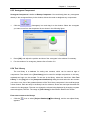
2
2
Installation of EV5000
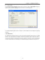
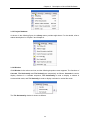
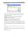
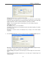
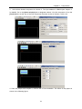
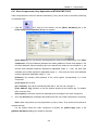
Follow the instructions of the InstallShield Wizard, click the Next button, enter the user’s
information, as shown in the following figure:
3
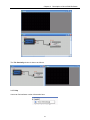
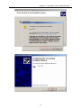
Click Finish to complete the installation.
4
To run the program, find the executable program under the directory of Start Æ Programs Æ
Stepservo Æ ev5000.
8
Chapter 1
Installation of EV5000
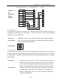
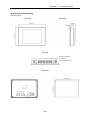
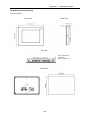
1.2 Interface Diagram
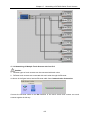
The COM0/COM1 ports in MT5000 and MT4000 can be connected to a PC or a PLC. The
MT5000 and MT4000 have very powerful communication capability. The MT5000 provides one
Ethernet interface (the MT4000 does not have any Ethernet interface), one USB interface, one
print interface, and two serial ports). Therefore, the MT5000 and MT4000 are capable of
communications with most devices with communication capabilities. Thus, it can be seen that the
MT5000 and MT4000 have wide applications. These interfaces will be described one by one in the
following sections:
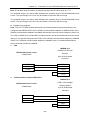
1.2.1 Serial Ports
Presently the MT5000/4000 has two serial ports, marked COM0 and COM1.
The two ports are respectively male and female connectors for the convenience of differentiation.
The difference between their pins lies in PIN 7 and PIN 8.
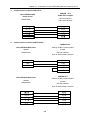
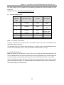
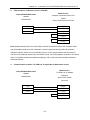
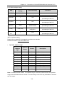
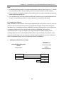
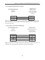
COM0 is a 9-pin male connector, with the pinout definition as follows:
P1
GND
TX+
TXPC_TXD
TXD_PLC
PC_RXD
RXD_PLC
RX+(B)
RX-(A)
5
9
4
8
3
7
2
6
1
COM0 MALE
PC232/PLC232-NO HARDWARE CONTROL/485/422
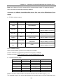
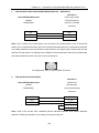
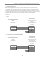
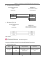
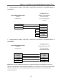
COM1 is a 9-pin female connector, with the pinout as follows. Its difference from COM0 is that its
PC_RXD and PC_TXD are replaced with TRS_PLC and CTS_PLC hardware control connected to
PLC 232.
9
Chapter 1
Installation of EV5000
P2
5
9
4
8
3
7
2
6
1
GND
TX+
TXRTS_PLC
TXD_PLC
CTS_PLC
RXD_PLC
RX+(B)
RX-(A)
COM1 FEMALE
PLC232-HARDWARE CONTROL/485/422
1.2.2
Ethernet Interface
The MT5000 (MT4000 does not have any Ethernet interface) has an adaptive 10M/100M network
interface which can implement such functions as program download, online simulation and
interconnection of multiple devices.
With the use of the Ethernet, we can conduct the following operations:
(1)
Downloading programs from a PC to the HMI: The download is much faster than
download through an RS232 or USB port;
(2)
Implementing networking and interconnection of multiple HMIs;
(3)
Implementing communications between the HMI and field equipment.
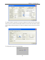
The settings of the Ethernet interface are as follows:
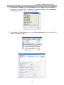
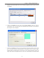
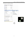
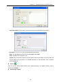
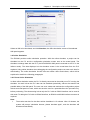
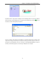
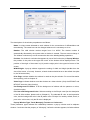
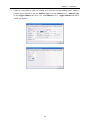
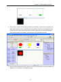
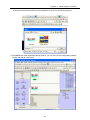
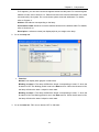
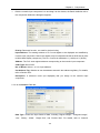
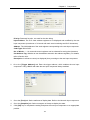
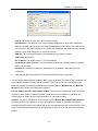
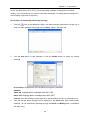
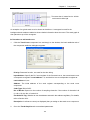
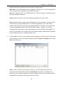
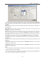
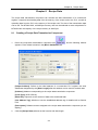
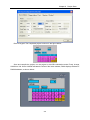
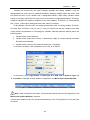
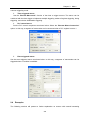
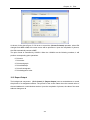
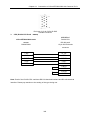
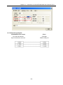
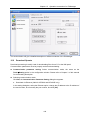
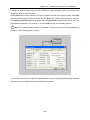
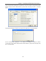
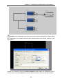
(1) In the Project Window, double click the HMI icon, and the following dialog box appears:
(2) Set the IP Address and Port Number. Note that the IP addresses over the same network
10
Chapter 1
Installation of EV5000
should not be the same.
(3) After saving the compilation, download the IP address of the HMI through the serial port or
USB port. After download, the IP address on the screen will change to the IP address set in the
above figure.
(4) If the Ethernet interface is used to download the program, the IP address should be set to be
different from that of the PC. To modify the IP address, you may turn the two DIP switches in the
rear of the touch screen to “ON”, and then reset the HMI to enter the built-in SETUP window.
(5) Click Options in the Tools menu, open the compilation download option, select Ethernet for
the Download Device, and set the IP Address and Port of the touch screen.
11
Chapter 1
Installation of EV5000
Note: After project download, the IP address of the screen will automatically change to
the IP address set in the HMI Properties window. If the IP address set in the HMI Properties
interface is inconsistent with that set in the Compilation Download Options window, download
by use of the old IP address will fail. In this case, it is necessary to adjust the IP address in
Compilation Download Options window, or enter the SETUP state to modify the current IP
address of the touch screen.
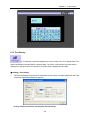
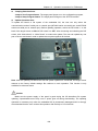
1.2.3 Printer Interface
The MT5000 series and the MT4400T/MT4500T series provide a printer interface. The interface
setting is the same as a PC interface. The MT4300 series provides a 15-pin print interface.
Parallel Print Port (15-pin D-SUB Female Connector)
The user can print window, events, texts and bitmaps online.
12
Chapter 1
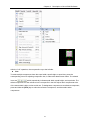
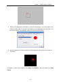
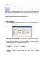
(1)
Installation of EV5000
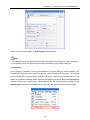
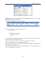
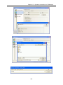
Printer setting
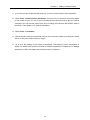
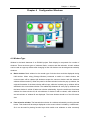
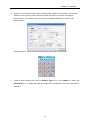
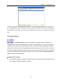
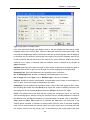
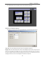
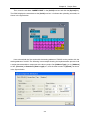
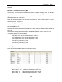
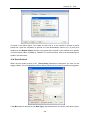
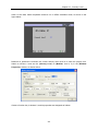
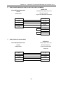
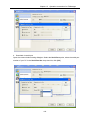
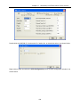
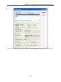
In the Project Structure Window, double click the HMI icon, and the HMI Attribute dialog box
appears. Enter the Printer Settings window, as shown in the following figure:
For printing methods, please refer to Chapter 10 which details the print settings and printing
methods.
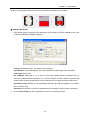
1.2.4 USB Interface
Our MT5000 and MT4000 provide you with a high-speed download channel, that is, the USB
interface. The USB interface will greatly increase the download speed, without the need of
knowing the IP address of the target touch screen in advance. Therefore, you are recommended
to use the USB interface for downloading. For download operations, please refer to Section 3.9.
13
Chapter 2 Making a Simple Project
Chapter 2
Creating a Simple Project
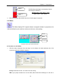
“Ease of use“ is one of the most outstanding advantage of our EV5000 configuration software. In
this chapter, a step-by-step instruction of creating a simple project containing only one switch
control part is given, which makes the user getting started with the basic procedure of project
making. More sophisticated projects can be created with similar methods.
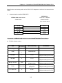
2.1 New an empty Project
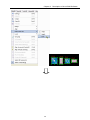
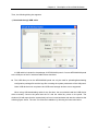
X Part 1:New an empty project.
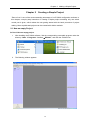
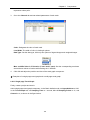
1.
After installing the EV5000 software, find the corresponding executable program under the
directory “Start Æ Programs Æ eview Æ EV5000”, and click the EV5000 icon.
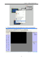
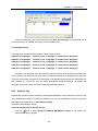
2.
The following window appears:
14
Chapter 2 Making a Simple Project
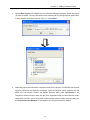
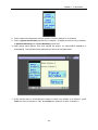
3.
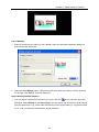
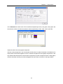
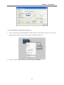
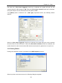
Choose New Project in the File menu, the following dialog box appears. Name the project
you want to create. You may also click [>>] to select a path for storing the new project files.
In this example, the project name is “test_01”. Click Create.
4.
Select the proper communication connection mode for the project. The MT5000 touch penel
supports serial port and Ethernet connection, while the MT4000 series supports only the
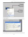
serial port now (further revision will support Ethernet also). Click Connection in the
Component Library window, there are two icons represent serial port and Ethernet mode,
respectively. Click the icon of the proper communication mode to select, hold and drag it to
the Project Structure Window. A wire appears in the Project Structure Window.
15
Chapter 2 Making a Simple Project
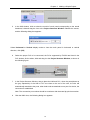
5.
In the HMI window, click to select the model of touch panel corresponding to the actual
hardware, hold and drag the icon to the Project Structure Window. Release the mouse,
and the following dialog box appears:
Select Horizontal or Vertical display mode to view the touch panel in horizontal or vertical
direction, click [OK].
6.
Select the proper PLC to be connected, the PLCs supported by EV5000 are listed in the
PLC window, click to select, hold and drag it to the Project Structure Window, as shown in
the following figure:
7.
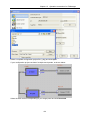
In the Project Structure Window, drag to place the HMI and PLC, when the ports(shown as
the gray trapezoids) of the HMI or PLC are close to the end of the wire, the wire will
automatically attached to the ports, when both ends are attached to one port of a device, the
connection is established.
Note: The connection port number should be consistent with the actual physical connection.
8.
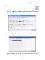
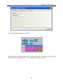
Click the HMI0 icon, the following dialog box appears:
16
Chapter 2 Making a Simple Project
Set the IP Address and Port Number of the touch panel in this dialog box. If there is only one
touch panel in your design and you will not use the function of indirect online simulation or
download the project file to the panel via Ethernet, you can simply skip this step. If you use
functions such as multi-HMI interconnection via Ethernet or Ethernet download, please allocate a
unique IP address to your touch pannel according to the actual situations of the LAN (Local Area
Network). If there is no conflict over the network, it is recommended not to change the default port
number.
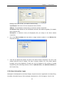
9.
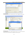
Double click the PLC icon, set Station No. to be the corresponding PLC station number.
17
Chapter 2 Making a Simple Project
10.
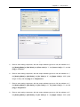
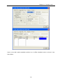
Set connection parameters:
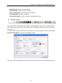
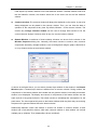
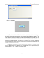
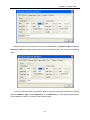
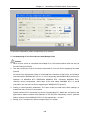
Double click the HMI0 icon to show the HMI Attribute window. Click the Serial Port1 Setting tab,
set the parameters of COM1 settings in this window (If the PLC is connected to COM0, please
modify the parameters of COM0, as shown in the following figure:
In accordance with your PLC connection, set the Type to be RS232, RS485-4W or RS485-2W,
and set other properties like Baud Rate、Data Bits 、Parity and Stop Bits. If you are not an
advanced user, do not change the default settings in the right column.
11. Select “File”-> Save” on the menu to save the project.
18
Chapter 2 Making a Simple Project
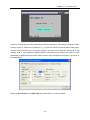
12. Select Tools Æ Compile, or press the Compile icon on the toolbar. After the compilation is
completed, a message box “Compilation completed” appears in the Compilation
Information Window, as shown in the following figure:
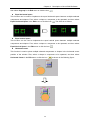
13. Select Tools -> offline Simulation, or press the Offline Simulation icon on the toolbar, as
shown in the following figure.
19
Chapter 2 Making a Simple Project
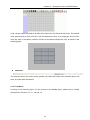
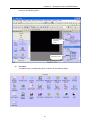
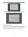
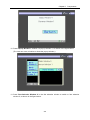
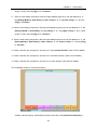
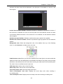
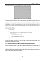
Click Simulate, the simulation window of the empty project we have created appears, as shown in
the following figure:
The project does not have any components and cannot execute any operations.
To exit the simulation program, right click in the simulation window area and click close or directly
press the Spacebar .
2.2 Adding a Switch Component
X Part 2: Adding a switch component to the project.
1.
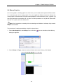
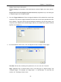
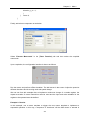
In the Project Structure Window, select the HMI icon and right click, click Edit
Configuration in the shortcut menu, as shown in the following figure:
20
Chapter 2 Making a Simple Project
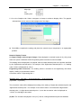
2.
The program switches to the window editing mode, as shown in the following figure:
21
Chapter 2 Making a Simple Project
3.
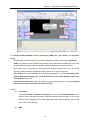
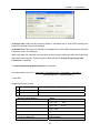
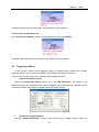
In the PLC Components frame in the graph element window on the left, click
,
hold, drag and drop it to the configuration screen editing area. after dropping, the General
dialog box in the Bit Control Components appears. Set the input/output address of the bit
control component, as shown in the following figure:
4.
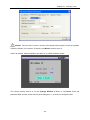
Switch to the Switch tab. Set the Switch Type. Select Toggle Switch from the list, as
shown in the following figure:
5.
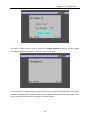
Switch to the Tag tab, select Use Tag, enter the texts corresponding to state 0 and 1 in
22
Chapter 2 Making a Simple Project
Content, and select the label color. (You can modify the alignment mode, font size and color
of the labels)
6.
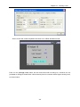
Switch to the Graphics tab and select the Use Vector Graphics check box. Select a
wanted shape. Here, the switch shown in the following figure is selected. For the making of
the vectogram, refer to Chapter 5.
7.
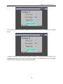
Switch to the Position tab. There are four inputboxes showing the position and size of the
part. “Left” inputbox holds the horizontal position of the upper left corner of the part, “Upper”
inputbox holds the vertical position of that corner, the unit of these inputboxes is pixel. The
origin of the screen is the upper left corner. So the “Left” value should not exceed the width
23
Chapter 2 Making a Simple Project
of the screen and the “upper” value should not exceed the length. For a screen of the
resolution of 320*240, the maxim of “left” is 319 and the maxim of “upper” is 239. “Width” is
the width of the part shown in the screen and “Length” is the length of it. Also, the maxim of
these two inputboxes should not exceed the size of the screen.
8.
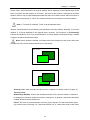
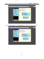
Click OK to close the dialog box. The component in place is shown as follows:
9.
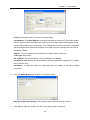
Select File->Save on the menubar, then select the menu Tools Æ Compile. If no error
occurs during the compilation, the project is completed.
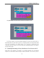
10. Select ToolsÆ Offline Simulation Æ Simulation. Thus, you can view the switch you have
added to the project. You may click it to switch between its ON/OFF state, which acts as the
same as a real switch, as shown in the following figure:
24
Chapter 2 Making a Simple Project
11. If you have set the IP address(see page 20), you may use the indirect online simulation.
12. Select Tools ÆIndirect Online Simulation. You may use your mouse to control the switch
on the screen of your PC, and it can be found that the output point Q0 of the PLC can be
controlled. You may use the output of the PLC to change over between the ON/OFF state of
the switch. (See chapter 3 for detail of simulation)
13. Select Tools Æ Download.
14. After download, reset the touch panel, and you can control the switch by touching the switch
shown on the panel screen with your finger.
15. Up to now, the making of the switch is completed. The making of other components is
similar. For details, refer to the introduction to related components in Chapter 6. For detailed
operations of offline simulation and download, refer to Chapter 3.
25
Chapter 3 Description of the eV5000 Software
Chapter 3
Description of the EV5000 Software
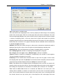
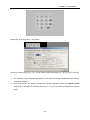
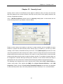
3.1 User Interface of EV5000
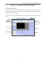
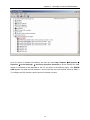
Run the EV5000 software, create an empty project by the procedures described in Chapter 2, the
EV5000 interface will show the contents as shown in the following figure. The name and function
of each item are described as follows:
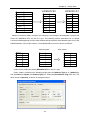
You may also right click in the View or toolbar, to view the toolbars, as shown in the following
figure:
26
Chapter 3 Description of the eV5000 Software
a. Title bar
b. Menu bar
The menu bar provides menus for selecting various groups of commands. If one of these
menus is selected, the corresponding dropdown menu appears. Each dropdown menu
provides a group of related commands.
c. Basic toolbar
The basic toolbar provides tool icons like Create Project, Open Project, Cut, and Paste.
For details, refer to the icon descriptions in Section 3.1.4.
d. Drawing toolbar
Each icon stands for a drawing function as it shows. The drawing tools include line tool,
rectangle tool, ellipse/circle tool, arc tool, polygon tool and text tool. For detailed
information, refer to Section 3.1.4.
e. Fill effect toolbar
This toolbar provides tools used for filling the screen background or areas within a
enclosed barriers such as rectangle, ellipse and sector. Each icon represents a filling style.
For details, refer to the descriptions in Section 3.1.4.
f.
Position adjustment toolbar
It is used for adjusting the position of components, such as, Align Top, Align Bottom, Justify,
Align right, Equal Size, Cascade, Group, flip, and so on.
For details, refer to the descriptions in Section 3.1.4.
27
Chapter 3 Description of the eV5000 Software
g. System toolbar
It is used for compiling, downloading and simulating a project.
For details, refer to the descriptions in Section 3.1.4.
h. Line width toolbar
It is used for adjusting the line width.
For details, refer to the descriptions in Section 3.1.4.
i.
Turn-to-page toolbar
It is used for scrolling forward and backward within the pages of a project.
For details, refer to the descriptions in Section 3.1.4.
j.
Database toolbar
It includes text library tool, alarm messages tool, address labels tool, PLC control tool and
event messages tool.
For details, refer to the descriptions in Section 3.1.4.
k. Code compilation toolbar
It is used for controlling the compilation of codes.
For details, refer to the descriptions in Section 3.1.4.
l.
Line style toolbar
This toolbar is used for selecting the line style: with or without an arrow, be a dotted line or
solid line. The style of lines,arcs and the outline of rectangles are also set by this toolbar
For details, refer to the descriptions in Section 3.1.4.
m. Graph element window
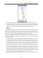
The Graph element window has five optional columns:
Connector: Used to select the type of communication link;
HMI: Used to select the HMI type;
PLC: Used to select the PLC type;
PLC parts: Used to select various configuration parts related to PLC registers;
Function parts: Used to select various functional parts.
n. Project construct window
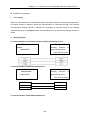
The Project construct window shows the tree relationship between project windows and
parts of the PLC and HMI in the entire project with a tree diagram.
For details, refer to the descriptions in Section 3.4.
o. Project files window
The Project files window indicates the relationship between the touch panel and bitmap
files of the project in tree structure.
For details, refer to the descriptions in Section 3.3.
p. Compile information window
For details, refer to the descriptions in Section 3.5.
28
Chapter 3 Description of the eV5000 Software
q. Component list window
For details, refer to the descriptions in Section 3.6.
r.
Status bar
The Status bar shows the current mouse position, width/height of the target object, edit
status, and so on.
s. Configuration window
The user can draw the configuration in this window.
Note: To change the color of the fonts and the fill color of the window and rectangles, directly
click the line color button
.
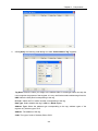
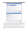
3.1.1 The File Menu
z
New Project)
Select New Project in the [File] menu or click the icon
to create a new project.
Enter a project name, Press [OK], a new project will be created.
z
Open Project
Select Open Project in the File menu, or click the
29
icon to open an existing project.
Chapter 3 Description of the eV5000 Software
Select a project file(.wpj file) to be opened, click Open or double click the project file to open it.
z
Close Project
Select Close Project in the File menu, the current project will be closed. If it has not been saved
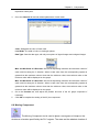
before, the program will ask the user to save it.
30
Chapter 3 Description of the eV5000 Software
After clicking Close Project
all the current windows will be closed, as shown below:
31
Chapter 3 Description of the eV5000 Software
z
Files recently opened: the program automatically remember the most recently opened 3
files’ name and path, the user can quickly open them in the “File” Menu.
z
Exit
Select Exit in the File menu to exit the EV5000 configuration software.
32
Chapter 3 Description of the eV5000 Software
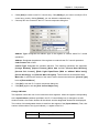
3.1.2 Edit
z
Undo
Use this function to undo the latest operation, the screen will return to the state before this
operation. click the icon
z
or select Undo in the Edit menu will activate this function.
Redo
Use this function to redo the operation which has just been undone by the Undo operation. Click
or select Redo in the Edit menu.
The Undo/ Redo support the following operations:
1. Drag a component from a component library window
2. Draw a static component
3. Move an object
4. Adjust the size of an object
5. All operations on the position toolbar
6. Line width, line style, and arrows
7. Fill style of an object
8. Frame color of an object
9. Fill color of an object
10. set to Top layer, set to bottom layer
11. Group and ungroup of multiple parts
12. Cut, copy, paste and delete of objects
13. Multiple copy
To add any component to the screen or to make any change to the screen, the user can use the
Undo/Redo function. As shown in the following figure, add a switch component to the screen:
33
Chapter 3 Description of the eV5000 Software
Press Undo:
The switch part disappears, leaving a blank screen.
Then click Redo:
The switch re-appears
The software supports the “Undo/Redo” operation of the latest ONE operation.
z
Cut, copy, paste and delete
Select one or more components, you can conduct such operations as Cut, Copy and Paste. Their
corresponding icons are
. Their demonstration is omitted here.
34
Chapter 3 Description of the eV5000 Software
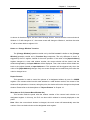
z
Nuage
Select a part, the position of the object can be adjusted by using the Nuage tools, or you can use
the Nuage icon to move the component. Every time when you click Tune, the component will
move by the distance of one pixel. Its corresponding icons are
indicating
, respectively
Move Left by One Pixel , Move Right by One Pixel , Move Up by One Pixel , and
Move Down by One Pixel , which correspond to the contents of the Nuage in the Edit menu one
by one. A simple method to use the “Nuage” function is to use the direction keys of the keypad, to
move the component conveniently.
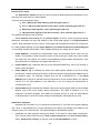
z
Align
It is used to implement the Justify the alignment of multiple parts. With the Alignment tools, users
can Align right, Align Top, Align Bottom, Vertical Center and Horizontal Center. Their
corresponding icons are
. Here, we only conduct the “Left” operation. The
35
Chapter 3 Description of the eV5000 Software
effect after the “Left” operation is as follows:
36
Chapter 3 Description of the eV5000 Software
After the “Left” operation, the two parts line up to the left side.
z
Size
To make multiple components have the equal width, equal height or equal size, press the
corresponding icons for adjusting component size, or select the related menu items. The related
icons are
, which respectively indicate equal width, equal height, and equal size. The
default component for size reference is the component in the left. Adjust other components to be
of the same width, height or size as this one. To designate a component as a reference component,
press and hold the [Shift] key to select the reference component, and then select other
components.
37
Chapter 3 Description of the eV5000 Software
38
Chapter 3 Description of the eV5000 Software
z
Layer
If multiple components are overlapped, you can use the icons
(Top, Bottom) or selectSet
Top Layer andSet Bottom Layer in the Layer submenu in the Edit menu to change the layer
sequence of the components.
First select a component, then click the related icon to set the component to the expected layer.
The components on the top layer are always displayed above the components on the layers
below.
Top
z
Group/Ungroup
This function can be used to group multiple selected components or shapes, so that they can be
used as a single component. To group multiple components, select these components, and then
select Group in the Edit menu or click the icon
39
. To ungroup, select the grouped entity, and
Chapter 3 Description of the eV5000 Software
then select Ungroup in the Edit menu or click the icon
z
.
Equal horizontal space
This function can be used to implement the equal horizontal space between multiple selected
components and shapes. First, select a shape or component to be operated, and then select
. The effect is as follows:
Equal Horizontal Space in the Edit menu or click the icon
z
Equal vertical space
This function can be used to implement the equal vertical space between multiple selected
components and shapes. First, select a shape or component to be operated, and then select
Equal Vertical Space in the Edit menu or click the icon
z
.
Horizontal center
This function is used to place multiple selected components or shapes in the horizontal center
position of the window. First, select a shape or component to be operated, and then select
Horizontal Center in the Edit menu or click the icon
40
, as shown in the following figure:
Chapter 3 Description of the eV5000 Software
z
Vertical center
This function is used to place multiple selected components or shapes in the vertical center
position of the window. First, select a shape or component to be operated, and then select Vertical
Center in the Edit menu or click the icon
z
. The figure is omitted.
Flip and Rotate
Only shapes drawn by drawing tools can be flipped, such as straight lines, circles, and polygons.
Other components cannot be flipped. First, select a shape to be flipped, and then select
Flip
Horizontal:
left/right
Flip
flip
Flip Vertical: Flip up/down
Rotate for 90 degrees: rotate
anticlockwise for 90 degrees
Horizontally,
Flip Vertically and Rotate 90º in the Edit menu or select the icon
flip the component.
41
to
Chapter 3 Description of the eV5000 Software
3.1.3 View
The View menu provides control over the display of various toolbars and windows. To make the
expected toolbars and windows visible in the user interface, check the corresponding item on the
View menu.
z
Standard toolbar: As shown in the figure, the contents of the standard toolbar correspond to
the contents in the menu in turn:
New Project: Create a project;
Open Project: Open an existing project;
Save: Save the current project;
Save All Active Files: Save all the currently opened active files;
Cut: Cut;
42
Chapter 3 Description of the eV5000 Software
Copy: Copy;
Paste: Paste;
Multiple Paste: Multiple copy;
Delete: Delete a component;
Cancel: Cancel the latest operation;
Restore: Restore the latest cancelled operation;
Print Preview: Print preview;
Print: Print;
Properties: Display the properties of an object;
Show Component Name: Show the name of a component;
About: EV5000 version description.
z
Multi-Copy
This function is used to make multiple copies of selected parts, which can save more time. Select
components, and click the
icon to copy multiple components, as shown in the following
figure:
43
Chapter 3 Description of the eV5000 Software
A configuration window appears for entering the copy quantity, interval of the copies and some
other options.
Attribution: To change the attributions of a component, select the component, double click it or
click the icon
, the Properties dialog box of the component appears. The user can make
editing in this dialog box.
z
Database Toolbar: As shown in the following figure, the contents of the items in the menu
correspond to each other, which are as follows in turn:
Text Library: Stores text tags;
Address tags: Stores address tags
Alarm Information Logon: Enter alarm messages;
Event Information Logon: Enter event messages;
PLC Control: Adds PLC control components;
(New Graphics): Creates a vectogram or a bitmap;
(Import Graph Library): Imports a vectogram or a bitmap;
(Add Macrocode): Adds a macrocode;
(Import Recipe Data File): Import a Recipe data file;
(Edit Intitial Window): Click this button to switch the window to the startup screen edit
window, where you can edit the initial display window upon the power-on startup of the HMI
panel, as shown in the following figure:
44
Chapter 3 Description of the eV5000 Software
The default initial window is the logo of Kinco Electric Ltd.
z
Line style toolbar: As shown in the following figure, the contents of the items in the menu
correspond to each other in turn:
z
Position adjustment toolbar
(Move Left by One Pixel): Sets a component to move left by one pixel;
(Move Right by One Pixel): Sets a component to move right by one pixel;
(Move Up by One Pixel): Sets a component to move upward by one pixel;
(Move Down by One Pixel): Sets a component to move downward by one pixel;
(Left): If the text content exceeds two lines, the text lines will align to the left(also applicable to
45
Chapter 3 Description of the eV5000 Software
components).
(Align Right): If the text content exceeds two lines, the text lines will align to the right (also
applicable to components).
(Align Top): Sets multiple components in top alignment mode.
(Align Bottom): Sets multiple components in bottom alignment mode.
(Vertical Center): If the text content exceeds two lines, the text will be arranged in the vertical
center alignment mode (also applicable to components).
(Horizontal Center): If the text content exceeds two lines, the text will be arranged in the
horizontal center alignment mode (also applicable to components).
(Equal Width): Sets equal width for multiple components.
(Equal Height): Sets equal height for multiple components.
(Equal Size): Sets equal size for multiple components.
(Top): Sets a component to be located in the topmost layer.
(Bottom): Sets a component to be located in the bottommost layer.
(Group): Includes multiple components into one group.
(Ungroup): Dissects the grouped parts into multiple discrete parts.
(Equal Horizontal Space): Sets equal horizontal space for multiple components.
(Equal Vertical Space): Sets equal vertical space for multiple components.
(Flip Vertical): Flip up/down.
(Flip Horizontal): Flip left/right.
(Rotate for 90º): Rotate for 90 degrees counter-clock wisely.
z
Tag Position toolbar
Some component has a tag on it. By default, the tag is in the center of the component.
But when the component has been stretched or resized, the tag may no longer lay in the
center. To position the tag more precisely, click the tag to select it, then the tag position tools
are enabled. The tools listed here are: Align the tags to the left, to the right, to the top, to the
bottom, align horizontal midline and align vertical midline.
z
Drawing toolbar
46
Chapter 3 Description of the eV5000 Software
The contents of the drawing toolbar are arranged in the following order:
Select: Selects a single component;
Straight Line: Draws a straight line;
Curve: Draws a curve;
Rectangle: draws a rectangle;
Rounded Rectangle: Draws a rounded rectangle;
Polyline: Draws a continuous straight line;
Polygon: Draws a polygon;
Circle/Ellipse: Draws a circle/ellipse;
Sector: Draws a sector;
Text: Adds a text;
Picture: Imports a picture to the bitmap library;
Line Color: Sets the color of a line;
Fill Color: Sets the filling color;
Background Spacing Point: Sets the background spacing point;
Transparent Color: Implements transparent color effect of an added bitmap;
Gray Scale: switches the bitmap between color and gray.
47
Chapter 3 Description of the eV5000 Software
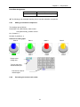
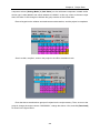
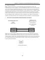
In the palette of color-related tools, we provide 40 optional colors, as shown in the following figure:
In addition, besides the 40 colors listed above, you may make a customized setting of the color.
Select Custom, and the following dialog box appears:
48
Chapter 3 Description of the eV5000 Software
In this dialog box, you may customize any shape color you want. we provide more color schemes
in the color properties list.
The users can customize their own color when needed.
z Selecting components
Methods for using selecting components:
1. Directly select: Click a component to be selected directly;
2. Select all components: Select Select All Components in the Edit menu, and all
components in the current screen will be selected.
When the direct select tool is activated, Click a component,with the Ctrl key hold will make a copy
of the component .
49
Chapter 3 Description of the eV5000 Software
Note: To select multiple components or to enter the multiple selecting mode, drag the mouse
and select at least one part, then press and hold the [Shift] key, additional parts can be selected.
z
Modifying part size
You can click a component to change its size in the following method: Click to select a part, select
anyone among the eight green pints of the component, and drag with your mouse, as shown in the
following figure:
z
Part Fill and Frame:
To change the change the color of the part outline or the filling color, select a component, and click
the arrow after
Line Color icon to change the frame color. To change the fill color, click the
arrow after the black box, as shown in the following figure:
z
Text
Click the text icon
, the text dialog box appears, as shown in the following figure:
50
Chapter 3 Description of the eV5000 Software
Content: Shows the text contents on the parts. When entering text, you can press the [Enter]
key to start a new line.
Graphics Mode: In this mode, you can change the font size, font, font style, and so on. Click
Vector Font to show the font property setting dialog box, as shown in the following figure:
Tag Mode: In this mode, you can only change the font size, align mode and color.
51
Chapter 3 Description of the eV5000 Software
Text Library Mode: In this mode, you can use the text pre-defined in the text library.
Font Size: 8, 16, 24, 32, 48, 64, 72 and 96 pixels are optional.
Align: The text alignment mode can be Left, Right, and Center.
Color: Indicates the text display color.
Content: Shows the text content on the part. When using the text library, the text content can
only be edited in the text library. For detailed description of the text library, refer to Section
6.33 in Chapter 6.
z
Picture
This icon can be used to add pictures when creating bitmaps. For related contents, refer to
Section 5.6, “Bitmap”.
z
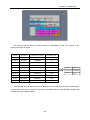
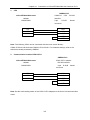
Switch page Toolbar
52
Chapter 3 Description of the eV5000 Software
Add Window
Previous Window
Current Window
Zoom Out
Zoom In
Next Window
Add Window: Adds a configuration window;
Previous Page: Goes to the previous configuration window;
Current Page: Shows the current configuration window;
Next Page: Goes to the next configuration window;
Zoom in: Zooms in the current window;
Zoom Multiple: 100%, 200% and 300% are optional
Zoom out: Zooms out the current window.
z
Line style toolbar
It is used to select the line width, the number indicates the pounds of the line width.
z
System toolbar
Compile: Compiles the current project and checks whether there is any error. Projects have
to be compiled before download or simulation, or the download and simulation tools are
disabled.
Download: Downloads a project to the HMI panel;
Offline Simulation: Used for offline simulation of a project;
Indirect Online Simulation: Used for indirect online simulation of a project;
Direct Online Simulation: Used for direct online simulation of a project;
z
Code editing toolbar
53
Chapter 3 Description of the eV5000 Software
Add Bookmark: Creates a new bookmark;
Next Bookmark: Shows the next bookmark;
Previous Bookmark: Shows the previous bookmark;
Delete Bookmark: Deletes a bookmark;
Variable Edit Window: Opens or closes the variable edit window.
z
Fill Effect Toolbar
It is used to select various filling effect shapes. The filling patterns above can be used for shapes
like rectangle, ellipse and sector. The background of configuration window can also be filled with
these patterns.
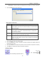
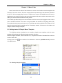
To fill the current window, double click the window to show the properties window. Select (Use
Background Fill Effect), as shown in the following figure:
Select a fill color and background color, and then select a fill style, as shown in the following figure:
54
Chapter 3 Description of the eV5000 Software
To fill a shape, select the shape to be filled, then click one of the above fill style icons. The method
is the same as that for filling a window. The only difference is that, for a component, the line color
is the line color of the pattern, while the fill color is the pattern background color, as shown in the
following figure:
z
Status bar
The stats bar shows the current mouse position, the width and height of the selected object, edit
state, and other state information.
3.1.4 Tools Menu
As shown in the following figure, for the contents of the (Tools) menu, please refer to related
descriptions in Sections 3.5, 3.7, 3.8 and 3.9.
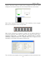
55
Chapter 3 Description of the eV5000 Software
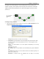
3.1.5 Project Database
As shown in the following figure, the Library menu provides eight items. For the details, refer to
related descriptions in Chapter 5 and Chapter 6.
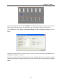
3.1.6 Window
Click Window in the main menu bar, and the following dropdown menu appears. The functions of
Cascade, Tile Horizontally and Tile Vertically are respectively as follows: Cascade is used to
display windows in a cascade sequence, Tile Horizontally is used to display a window in
Horizontal tile mode, and Tile Vertically is used to display a window in vertical tile mode.
The Tile Horizontally window is shown as follows:
56
Chapter 3 Description of the eV5000 Software
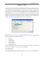
The Tile Vertically window is shown as follows:
3.1.7 Help
Users can find software version information here.
57
Chapter 3 Description of the eV5000 Software
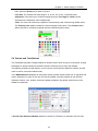
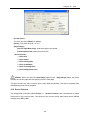
3.2 Graph element Window
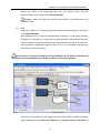
By default, there are three important windows displayed within the EV5000 user interface. They
are not real “windows”. The definition of “window” will be described in the next chapter. The
“window” here refers to a special area related to all components of a project. The three “windows”
provide global information of the whole project. The three windows are, Graph element Window,
Project File Window, and Project construct Window, which will be described one by one in the
following.
58
Chapter 3 Description of the eV5000 Software
Configuration
edit window
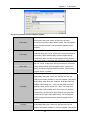
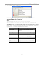
The Graph element Window includes (Connector), (HMI), PLC, (PLC Parts), and (Function
Parts).
(Connector): Includes serial port connection (Serial) and Ethernet connection (Ethernet).
(HMI): All models of eView MT4000 and MT5000 series HMI panel are listed here, the users
should select the proper model in accordance with the actual panel for their projects;
PLC: All the PLCs supported by eView HMI panel system are listed here; the user should
select the proper model in accordance with the actual PLCs for their projects;
(PLC Parts): All the parts related to PLC registers are listed here, including Bit Setting Part,
Switch, Multi-state Display Part, Trend Graph Part, XY Plot Part, Numeric Input Part,
Text Input part and so on;
(Functional Components): Parts for special functions are listed here, including Function
Key Part, Scale Part, Alarm Bar Part and Timer Part
Usage:
(1)
Connector:
If you select RS232 or RS485, click [Serial] icon, drag it to the Project Window. If you
want to use the Ethernet connection, click the Ethernet icon then drag it to the Project
Window. When dragging, the icon will appear like a wire. After dropping it, the wire will
stay in the Project Window.
(2)
HMI:
59
Chapter 3 Description of the eV5000 Software
Identify the model of the actual HMI panel you are currently using, click the
corresponding icon and drag it to the Project Window.
Caution: Make sure that the selected HMI model is consistent with your
hardware model.
(3)
PLC
Identify the model of PLC currently being used, click the corresponding icon and drag it
to the Project Window.
After selecting the PLC, HMI and communication connection, connect them properly.
(Drag the PLC and HMI icon to make the wire ends attached to the ports automatically.
Click and drag the wire ends towards the ports will yield the same result. To make sure
the connection is established, drag the HMI or PLC icon, the properly attached wire
ends will move with the mouse.)
Note: If there isn’t any PLC or HMI in the Project Window, the Project File Window and
the Project Construct Window will be blank, as shown in the following figure:
The
touch
screen
and
image library
are blank
HMI and PLC
all blank
Once the PLC and HMI icons are dragged into the project window, related information
will be displayed in the Project File Window and Project Construct Window, as
60
Chapter 3 Description of the eV5000 Software
shown in the following figure:
Touch screen displays
corresponding
contents
HMI0 and PLC have
corresponding contents
(4)
PLC parts
It includes various configuration parts, as shown in the following figure:
61
Chapter 3 Description of the eV5000 Software
After creating a project and switch to the configuration screen edit window, you can
drag parts to be used into the configuration window. For the detailed instruction for
using the PLC parts, please refer to Chapter 6.
(5)
Function Parts
Function parts include Function keys, Scale, Alarm Bar, Timer, and so on. For the
usage of them, please refer to Chapter 6.
Caution: In the Graph element Window, right click, and select Small Icon in the shortcut
menu, the icons will be displayed in the form of smaller icon, which can save the window area for
small displays, as shown in the following figure:
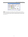
3.3 Project File Window
Files related to shape library and HMI panels are displayed in the Project Files Window, so there
are two branches in the tree structure: HMI and Graphic Library.
HMI:
The HMI folder contains *.whe file which is corresponding to the HMI icon in the Project Window,
For the first HMI panel, HMI0, the file is HMI0.whe, for HMI1, the filename is HMI1.whe. If there are
three HMI panels in the project, there are three *.whe files, HMI0.whe, HMI1.whe and HMI2.whe.
Double click the *.whe file will expand it, macrocode file and recipe file attached to the HMI panel
will appear.
62
Chapter 3 Description of the eV5000 Software
Click the symbol “+” or “-“ in the left of the icon to expand or collapse the directory tree.
To edit the file in the folders, double click it.
Caution: The configuration recipe file (.RCP) can only be imported and deleted, but cannot
be edited. To edit such a file, use other binary editing software.
Shape Library:
Shape Library folder contains all the vector graph and bitmap files imported to the current project.
Vector graph files are shown as *.vg files and bitmap files are shown as *.bg files. For the
description of vectogram and bitmap, please refer to Sections 5.5 and 5.6 in Chapter 5.
3.4 Project Window and Project Construct Window:
The Project Window is used to show the structure of the entire project. HMI panels, PLCs and
connection wires are shown in this window, as shown in the following figure:
63
Chapter 3 Description of the eV5000 Software
HMI: One HMI icon represents one actual HMI panel, the number after HMI helps the user
distinguish those panels. Right click on the HMI icon will popup its own shortcut menu, the
user can select in the menu to take expected operations on the corresponding panel.
PLC: One PLC icon represents one actual PLC. The number after PLC helps the user
distinguish those PLCs. Right click on the PLC icon will popup its own shortcut menu and the
user can select in the menu to edit the attribution of the corresponding PLC.
Wire: The wires shown in the Project Window represent the physical connection between
HMI and PLC. See page 59 for detail of connecting HMI and PLC.
The structural diagram is as follows:
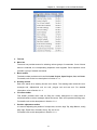
The detailed structure is shown in the Project Construct Window as follows:
See the figure above, the icons labeled “FrameX” represent the configuration windows of panel
marked as HMI1. “DW0" and “DW1” in the above figure represent parts in Window 1. The “+”
symbols indicate windows containing parts, click on the “+” will expand the tree and make the parts
of that window visible. Windows containing no parts don’t have that “+” symbol and can not be
64
Chapter 3 Description of the eV5000 Software
expanded. To collapse the expanded tree, click on the “-” symbols. If the user want to delete some
windows or parts, click to select and press DELETE key on the keypad, the selected frame or part
will be deleted.
PLC Attribution:
The first digit indicates the number of PLC, that is, the number designated to the PLC.
The digit after the colon indicates the station number of the PLC.
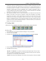
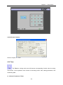
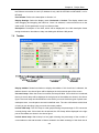
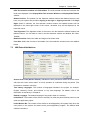
3.5 Compile Information Window
The Compile Information Window displays the complie progress and the compiling results,
indicates the errors when they occur, as shown in the following figure:
When a project is open, the Compilation Information Window will display the loaded information of
the project. When a project is being compiled, the Compile Information Window will display the
compilation progress and error messages if there are any.
65
Chapter 3 Description of the eV5000 Software
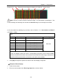
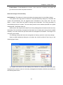
3.6 Component List Window
Select Component List Window under the View menu to open the Component List Window.
The window shows the information of all parts used in the project, including HMI panel number,
configuration frame number, part number, input PLC number, type of input address, input address,
output PLC number, type of output address and output address. Double click an entry will lead to
the configuration frame where the part is.
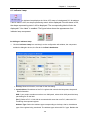
3.7 Offline Simulation
The EV5000 provides offline simulation function. During offline simulation, the program does not
accquire data from the PLC, but only read data from the local address. Therefore, all data
displayed on the configuration windows are static data. With the offline simulation, the user can
conveniently preview the configuration effect, without the need to download the program to the
touch screen every time. Therefore, lots of time for downloading is saved.
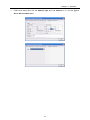
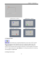
Select Offline Simulation in the Tools menu, or click the
appears:
66
icon, the following dialog box
Chapter 3 Description of the eV5000 Software
Select an HMI to be simulated, and click Simulate, the offline simulation screen of the selected
HMI panel appears.
3.8 Online Simulation
The EV5000 provides online simulation operation. With the online simulator, a project can be
simulated on the PC and the configuration simulation screen acts as the actual panel. The
simulator exchange data with the PLC (via MT4000/5000 HMI panel connected to the PC in the
indirect mode). The data displayed on the simulator screen is the actual data from the PLC
registers. Using online simulator when debugging the configuration project can save much time for
downloading. The online simulation function has two modes: direct and indirect, which will be
explained in detail in the following paragraphs.
3.8.1 Direct Online Simulation
In direct online simulation mode, the PLC is directly connected to the serial port of PC running the
simulator. Its merit is that the PLC data can be obtained dynamically, without the transfer and
possible delay of the HMI panel. The user can even create and evaluate the configuration project
without an actual panel on hand, which can save the cost for a potential client who just want to try
before purchasing. The shortcoming is that only the PLC with an RS232 interface can be used in
this mode. To debug the PLC with an RS485 interface, an RS232-to-485/422 interface convertor is
required.
Note:
1.
The maxim test time for the direct online simulation is 15 minutes. After 15 minutes, the
system will prompt “simulation timeout, please simulate again”, and the simulator will
shutdown automatically.
67
Chapter 3 Description of the eV5000 Software
2.
Only the RS232 communication mode can be used for direct online simulation.After the
compiling configuration project and establishing the physical connection between PLC and
PC, click the
button, the following dialog box appears:
Select the touch panel to simulate, select the COM ID of the computer to be connected to the PLC,
and click [Simulate] to start direct online simulation.
Note: Use the programming cable of PLC to connect PLC and PC and perform the simulation.
3.8.2 Indirect Online Simulation
In indirect online simulation mode, the simulator exchanges data with the PLC via the HMI panel
connected to PC. The simulation screen acts as the actual panel, clicking on the screen is the
same as touching the real panel. With indirect online simulator, lots of time for downloading is
saved.The user have to have the proper panel to perform the simulation. Connect the panel to PC
with USB cable or MT4000/5000 downloading cable or Ethernet cable. Connect the PLC to the
panel with the required communication cable. For more information about the communication
cable, refer to chapter 14.
After the compiling the project and connecting the PLC, HMI panel and PC properly, click the
button, the following dialog box appears:
68
Chapter 3 Description of the eV5000 Software
Select an HMI to be simulated, click [Simulate] to start simulation.
Note:
1. The MT5000 panels can perform indirect online simulation via the Ethernet, USB or serial port.
2. The MT4000 panels can perform indirect online simulation via the USB or serial port.
3.9 Download
After a project is compiled, it can be downloaded to the touch panel for actual operation. The
MT5000 panels provide three download methods: USB, Ethernet and serial port. The MT4000
panels provide two download modes: USB and serial port. Downloading via the Ethernet is the
fastest way, while downloading via the serial port and USB is a bit slower. Before download/upload,
the users must set the communication parameters first. Set the communication parameters in the
Setting Option submenu in the Tools menu in the menu bar, as shown in the following figure:
69
Chapter 3 Description of the eV5000 Software
Then, the following dialog box appears:
1) Download through USB cable
A USB cable is included in the package of MT5000/4000 panel. Connect MT5000/4000 panel
to the USB port of the PC with that cable before download.
z The USB-client port on the MT4000/5000 panel can only be used for uploading/downloading
configuration package file and the logo file or setting the system parameters of the HMI panel.
Other USB devices such as printers and USB mass storage devices are not supported.
When using USB downloading cable for the first time, the user should install the USB device
driver manually. Connect the panel and the PC with the cable fist, power on the panel. The
windows OS will report that the system had just found a new hardware and start the wizard as the
following figure shows. The user can finish the installation by following the instruction below.
70
Chapter 3 Description of the eV5000 Software
71
Chapter 3 Description of the eV5000 Software
72
Chapter 3 Description of the eV5000 Software
73
Chapter 3 Description of the eV5000 Software
74
Chapter 3 Description of the eV5000 Software
Once the driver is installed successfully, the user can select My Computer Æ Properties Æ
Hardware Æ Device Manager Æ Universal Serial Bus Controller to check whether the USB
device is connected to and identified by the PC, as shown in the following figure: (The EVIEW
USB appears only when the DIP switches 1 and 2 in the rear of the touch panel are set to “OFF”.)
To configure the DIP switches, remove the lit on the back of panel.
75
Chapter 3 Description of the eV5000 Software
Once the driver has been installed successfully, no more settings is needed. The user can use
the eView USB device after connecting and powering on the panel. To download through USB
cable, select “USB” for Download Device, as shown in the following figure:
76
Chapter 3 Description of the eV5000 Software
Compress Large Bitmap: In the numeric input box, the user can specify the limit of the
original file size of the bitmap which is imported into the project. The file size is counted by
bytes. When the bitmap file exceeds that limit, the complier will compress the bitmap for
downloading. Compression will save the storage space on the panel. This option is selected
by default.
2) Ethernet (For MT5000 panels only)
The Ethernet interface can be used for the downloading of the HMI configuration, the setting of the
HMI system parameters, and the indirect online simulation of the configuration. Furthermore,
multiple HMIs can be interconnected via the Ethernet to form a multi-HMI application.
77
Chapter 3 Description of the eV5000 Software
IP Address: Refers to the IP address of the HMI to be downloaded. In addition to this IP
address, the IP address of the PC should also be set. The two IP addresses should be in the
same network section, that is to say, the range of the IP address of your PC is: 192.168.0.1
~11/13 ~ 255. To implement normal download, the IP address of the HMI should be different
from that of the PC.
Port No.: A network is actually composed of seven layers of protocols. One of the most
important tasks of the Transport Layer is to provide a reliable end-to-end connection. Where,
the “end” here means the port. Of course, there are many ports, ranging from 0 to 65535. The
TCP/IP protocol has many ports. All the ports less than 1024 have clear definitions. You are
recommended to use ports above 1024. Set such a port to a port used for the touch screen.
Anyway, please make sure that your PC allows the use of this port. The setting procedure for
the PC port is as follows:
Network Connections (right click) Æ Properties Æ Local Area Connection (right click)
Æ Properties Æ Internet Protocol (TCP/IP) Æ Properties Æ Advanced Æ Options Æ
Enable TCP/IP Filtering Æ Properties
For details, refer to the following figure:
78
Chapter 3 Description of the eV5000 Software
Caution: 1. Normally, the port number does not need modification.
To change the port number, the port number in the Setting Option in the [Tools] menu should not
be the same as that in the Project Structure Window and HMI Properties, as shown in the following
figure:
79
Chapter 3 Description of the eV5000 Software
2. This port can be connected to a HUB or a SWITCH via a standard Ethernet cable (RJ45
straight-through cable) to access the LAN (Local Area Network), or can be directly connected to
the Ethernet port of the PC via an interconnection cable (RJ45 cross-over cable).
The network interface of the PC is directly connected to the touch screen via a cross-over cable.
Then, it is connected to the touch screen through the HUB via a straight-through cable.
3. If a user has enabled the firewall, an alert box will appear to ask which port the user wants to
access. Select "Enable", and download can be made. If all ports are disabled, disable the firewall.
4. The touch screen is directly connected to the network interface of the PC, and the IP address of
the PC should be changed to an address different from that of the touch screen. If the IP address
of the touch screen is 192.168.0.253, then IP address of the PC should be changed to
192.168.0.X. The first three digits should be the same, and the last digit should be different.
2) Downloading through Serial port
To use serial port as the downloading method, select “Serial Port” in the list, as the following figure
shows:
80
Chapter 3 Description of the eV5000 Software
Serial Port No.: Select a serial port you want to use. Make sure the port you designate is available
and the downloading cable is connected properly. The user can contact with Stepservo Ltd or
local distributor to get the serial downloading cable.
Note: Due to the low downloading speed, downloading through serial port will take a long
time to wait, thus it is not recommended as the downloading channel.
After selecting the downloading method and setting the required parameters, you can start
downloading by click the icon
. A dialog box will pop up after clicking the download icon.
According to the method you select, the dialog box looks a bit different, as the following figures
show:
81
Chapter 3 Description of the eV5000 Software
Except the downloading-method-related parameters displayed in gray boxes, there are some
options the users can set and should pay attention to.
82
Chapter 3 Description of the eV5000 Software
Select Section
The files to be downloaded to the panel are of three types: User Data File, Recipe File and Logo
File.The user can select any one of these files to be downloaded, which makes the downloading
more flexible and avoid wasting time for unnecessary download. The following paragraphs give an
introduction of these files.
User Data File: The configuration project files, including all the data of the configuration
windows and images, are packaged into a single user data file after being compiled. The
extension of the file type is .pkg. Only after the *.pkg file has been downloaded, the panel can
run the configuration project designed by the user.
Recipe File: This option is only available when there is a recipe file imported into the project
and affiliated to an HMI panel. The recipe file is stored in one SRAM chip on the mainboard of
the panel, with a backup battery to keep the data when the power is off.
LOGO File: Logo is the first picture displayed during the power-on stage, when the
embedded system has not been booted. So the picture is different from other pictures
displayed in the configuration windows. By editing the initial window, the user can create his
own logo file, whose expansion is *.logo. When the user want to change the current logo, he
must edit the initial window in the project and compile the project, then select the Logo File
check box and download the file to the panel. Once the logo file has been downloaded, there
is no need to download everytime if the user doesn’t want to change it. The logo will be
displayed everytime the panel is powered on. By default, the checkbox for logo file
downloading is unselected.
How to make your own logo?
Create a new project or open an existing one, make sure there is an HMI icon in the Project
Window. Click the
icon on the toolbar, or right click HMI icon in the Project Window to enter
the initial starting window edit window, as shown in the following figure:
83
Chapter 3 Description of the eV5000 Software
By default, there is a logo picture of Stepservo Ltd in the editing window. The user can replace it
with his own logo or other desired picture. To import an user-defined picture, click the
icon on
the toolbar, and the following dialog box appears:
Find your company’s logo image and click Open. The supported image format is bitmap, JPEG
image and GIF image, and the image to be imported as the logo should not larger than the size of
the panel. (For MT4300/5300, the size is 320*240, for MT4400/4500/5400/5500, the size is
640*480.) In the following figures, we use the logo of Stepservo as an example:
84
Chapter 3 Description of the eV5000 Software
After selecting the image and click “Open”, the logo image is imported into the editing window and
you can ajust the size and position of it. When the adjustment is done, save it and close the
window to return to the project window. Connect the HMI panel and PC, compile the project and
click “download” icon, the dialog box we have discussed above appears:
Select LOGO File checkbox and click Download. If the user only want to download the logo and
don’t want to download the user data file, unselect the User Data File checkbox.
85
Chapter 3 Description of the eV5000 Software
After the download is finished, click [OK].
Reset the panel, it will show the logo just been downloaded during the power-on stage. If no logo
file has been downloaded, the panel will display “LOGO Error!” instead.
86
Chapter 4 Windows
Chapter 4
Configuration Windows
4.1 Window Type
Window is the basic elements of an EV5000 project. Each display is composed of a number of
windows. There are three types of windows: Basic, common and fast selection. A basic window
can be used as a pop-up window after changing its size. All windows can be assigned as underlay
windows.
z
Basic window: Basic window is the normal type of window that would be displayed during
HMI runtime. When using (Change Window) command to switch to a basic window, the
current screen will be cleared (all windows except the common window and fast selection
window will be turned off). When the parts in the base window invoke the pop-up window, the
original information of the base window will be kept, while the invoked pop-up window will be
attached to the current base window. The relationship between all such pop-up windows and
the base window is a kind of father-son window relationship. Upon the switchover from base
window N to base window M, all sub-windows of window N will be closed, while window M
and sub-window of window M are displayed. The base window should be of the full-screen
size.
z
Fast selection window: The fast selection window is a window activated by touching the task
button. This window will be always displayed on the screen unless it’s hided by a task button.
So it can be used for placing function keys which switch over windows or other commonly
87
Chapter 4 Windows
used objects. By default, Window 2 is the fast selection window. If another window is set to be
the fast selection window, the window should be of the same size as the fast selection
window.
z
Common window: The common window will always be displayed on the screen. A part to be
always displayed can be placed in the common window. Thus, you can view the state or
operation of the component at any time. By default, Window 1 is the common window. The
function key Change Common window can be used to change other window to be the
current common window. However, there is only one current common window.
z
Bottom Window: A maximum of three underlay windows can be set for the window in the
Window Properties dialog box. Normally, the bottom window is used to store common
components shared by multiple windows, such as background images, graphs, titles and so
on. Any window can be set as a bottom window.
As shown in the figure above, you can select a bottom-layer window for the window in the Bottom
Window option. A bottom-layer window is different from a common window. During runtime, the
components of the bottom window are inserted into the general window, but actually this bottom
window is not displayed. The display and control of components of the bottom window are the
same as that of the general window. The bottom window is something like “transparent” for the
panel users, The users operate the parts on the bottom window while they think they are touching
the parts on the general window above the bottom window.
Relationship between screen and window: A screen can include: a common window, a base
window and a fast selection window, while each common window or base window can include
multiple pop-up windows. Their relationship is shown as follows:
88
Chapter 4 Windows
Screen
Base window
Fast selection
window
Common window
When the window switchover command is executed, the panel screen will clear all the current
windows (including the pop-up windows attached to the current basic window), and switch over to
the window to be displayed. However, the common window will always be displayed on the screen.
A pop-up window invoked by a direct or indirect window will not change the original contents of the
base window, and it is only attached to the base window. In the window property setting dialog box,
each window can be configured with a maximum of three bottom windows.
When a base window is invoked (the window number ranges from 0 to 3~ 65535), the touch panel
will show all parts in the window. In the meantime, if the window has a bottom window and all parts
in the bottom window will be displayed also. All the touchable parts (such as bit state setting,
function keys and so on) defined in the bottom window are also valid in the current window. The
common window is also displayed with all parts of it valid if it has been invoked by taskbar button.
The maxim number of windows in a project is 65535 (including all three types of windows). A
project can only have one fast selection window, however, the function key Change Fast
Selection Window can be used to switch over to another window and assign that one to be the
current fast selection window. For details, please refer to Section 6.29, “Function Key”.
After creating a new blank project, it has a default start window. Normally this window is numbered
“0” (to change the number, please change it in the HMI Properties dialog box in the project edit
window). In general, a project contains multiple windows. The valid window number ranges from 0
to 65535.
By default, Window 1 and Window 2 are the common window and fast selection window of a
project respectively. To change the default fast selection window and common window, double
click the HMI to modify the Touch Screen Extended Properties, as shown in the following figure:
89
Chapter 4 Windows
Note:
1. A maximum of 16 pop-up windows can be opened at the same time.
2. A window can only be opened once.
3. The function key Close Window cannot close direct or indirect windows, since the opening
or closing of a direct window is only related to the ON or OFF state of the bit address that
controls its switch, and the opening or closing of an indirect window is only related to the
data content of the word address of the indirect window. The function key Close Window
cannot change the values of these bit (word) addresses, so it cannot close these windows.
4. All pop-up windows are attached to the current basic window, so when the basic window
closes (or switches to other basic window), the attached pop-up windows will be closed
either. In this case, if you switch the window to the basic window previously opened again,
you may find that the original pop-up windows attached to this basic window still exist
(unless you run related command to close them).
5. The basic window must be of the full-screen size.
6. The fast selection window supports pop-up windows, but the “Truncated” feature of the
pop-up windows invoked by fast selection window can not be selected when setting the
property of that pop-up window.
7. Pop-up windows are attached to the windows which contain the parts that invoke those
pop-ups. So pop-up windows invoked by parts in the common window will exist until the
common window parts turn them off.
4.2 Window Properties
To set the window properties, double click on the blank area of the window or click the
show the window properties setting dialog box.
90
icon to
Chapter 4 Windows
The descriptions of the window properties are as follows:
Name: A unique name allocated to each window for the convenience of differentiation and
remembering. The name here can be changed whenever it is necessary to do so.
Number: The valid window number ranges from 0 to 65535. The window number is
automatically allocated by the system when a window is created. The user cannot change it.
The window numbers may not be consecutive due to the deleting/adding operations.
Position: If a window is a window that appears by use of the function key in Pop-up Window,
the position of the point at the upper left corner of the window will be displayed here. The
position of the origin of the screen is (0,0) and the origin point is the upper left corner of the
screen.
Width/Height: A pop-up window supports the setting of width and height (smaller than the
size of the screen, of course). However, a basic window should be set to the default size (that
is, the full-screen size).
Print Page: Indicate whether the window is used as the print window. For more information
about printing, refer to chapter 10.
Video Page: Indicate whether to set the window as a video window. (Only the MT5600T and
MT5700T have the video function)
Use Background Fill Effect: To fill the background of window with the patterns or colors,
check this option.
Fill Color and Background Color: Select according to the fill style used (for the description
of the fill effect toolbar, please refer to Chapter 3). The selected fill color is the impression
color, and the background color is the fill pattern color. Fill style 0 is used by default, that is, a
pure color. In this case, only the fill color is displayed.
Pop-up Window Type: Track, Monopoly, Truncate and Coherence.
These parameter types indicate the relationship between a pop-up window and its adjacent
window. If a window has the property of “Monopoly”, before the window appears, its father window
91
Chapter 4 Windows
will be frozen, and furthermore, the pop-up window will be displayed in the topmost layer all the
time. If a window has the property of “Truncate”, the frame of the window is restricted by its father
window, that is to say, the part displayed outside the frame of its father window will be truncated. If
a window has the property of “Track”, the window will track the movement of its father window.
Note: If “Truncate” is selected, “Track” must be selected either.
Window A and Window B in the following are attached to the base window. Normally, if you touch
Window A, it will be displayed in the topmost layer. However, if the property of [Coherence]is
selected for Window A, even if you touch Window A, it will not appear in the topmost layer. Instead,
it clings to its father window all the time.
Note: After a window is created, its number cannot be changed, but the name, frame and
background color can be changed whenever it is necessary.
Basic window
window A
window B
Basic window
Window A
Window B
Security Level: Used to set the security level for a window. For details, refer to Chapter 12,
“Security Level”.
Bottom-layer Window: Used to set the bottom window for the current window. A window to
be assigned as a bottom window must be an existing one. In general, components shared by
multiple windows can be placed here.
Frame: The frame is recommended to use for a pop-up window. For the frame width, select
any number among 0 through 16. If the frame width is not “0”, select other color for the frame.
92
Chapter 4 Windows
There are two ways for changing the window properties:
1. Double click the blank area in the window.
2. Do not select any component in the window. Click the
icon on the toolbar.
4.3 Creating a Window
Click
in the [Window Toolbar] to create a new window.
4.4 Opening a Window
After a window is created, make selection in the dropdown menu in the Window Toolbar, all
existing windows can be selected from the list. You may also click the
previous window. Click the
icon to display the
icon to display the next window. If you use a mouse with a wheel,
you can directly roll the wheel to change the window number.
93
Chapter 4 Windows
4.5 Deleting a Window
As shown in the above figure, in the Project Construct Window, select a window to be deleted,
and press the [Delete] key in your keypad. In this case, an alert box appears. Select [Yes] to
delete the window, all the components in the window will also be deleted. Be careful when using
this function.
Note: The deletion of base windows (Frames 0, 1, 2 and 3) are forbidden. Once they are
deleted, the project should not be downloaded into panel, or the panel will not operate normally..
4.6 Examples for Windows
Several basic examples will be given below to explain some basic operations about “window”.
◆ Example 1: We often need to write a special value into some registers as soon as a project
starts running or an application window is opened, to conduct initialization. For example, when
Frame0 starts up, LB0 is set to “ON”, and LW1 is set to “200”.
94
Chapter 4 Windows
1.
Create a bit setting part, with the Address Type set to LB, Address to “0”, and the Type to
Set to ON at window open.
95
Chapter 4 Windows
2.
Create a multi-state setting component, with the Address Type set to LW, Address to “1”,
Type to Set to ON at window open, and Set Value to “200”.
96
Chapter 4 Windows
3.
Create a Indicator lamp part, with the Address Type set to LB, and the Address to ”0”, to
display the state of bit register LB0.
97
Chapter 4 Windows
4.
Create a number display part, with the Address Type set to LW, and the Address to ”1”, to
display the state of LW1.
5.
The finished project window is shown as follows:
98
Chapter 4 Windows
6.
Save, compile and perform online simulation of the project: LB0 is set to ON, and LW1 is set
to 200.
Reference for this example: Section 6.1, “Indicator Lamp”, Section 6.2, “Bit Setting Component”,
Section 6.4, “Multi-State Setting” and Section 6.11, “Numeric Display” in Chapter 6.
◆Example 2: It is an example of pop-up keypad window for number entry. In many cases, we
need to conduct write operation for registers. If the keypad is fixed on the current window, it will
occupy too much screen area, so that the current window design space of the project is greatly
reduced. In this example, we use the direct pop-up window method to solve this problem. Assume
that LW0 is the register need an input operation.
99
Chapter 4 Windows
Note: The EV5000 software has a keypad in Window 3, which can be directly invoked, so
you do not have to create a keypad by yourself each time. To create your own keypad, please refer
to chapter 6.
100
Chapter 4 Windows
1.
Create a new project or open an existing one. Enter the window editing mode. Create a
numeric input component, with the Address Type set to LW, Address to ”0”, Address Type
in the Trigger Address tab set to “LB”, and Address in the
“9000”. (by default)
101
Trigger Address tab set to
Chapter 4 Windows
2.
Window 3 is built into the blank project wizard so after creating a new project, user can find
window 3 in the project construct window, double click the icon of frame 3 will open it:
set the Width to 145, Height to 190. The Window Properties dialog box is shown in the
following figure:
edit the window 3,put a number input keyboard in the center of the window.
3.
Create a direct window part, with the Address Type set to “LB”, Address to 9069, and
(Window No.) to “3”. Adjust the width and height of the component to be of the same size as
Window 3.
102
Chapter 4 Windows
The entire project is shown as follows:
Save, compile, and make offline simulation of the project:
103
Chapter 4 Windows
4.
Click Number Input part. Upon LW0 input, a keypad appears below the component for you to
input. After the input, the keypad automatically disappears, as shown in the following figure:
4.7 Window-related Components
Function keys directly related to windows include: Change Basic Window, Return to Previous
Window, Change Common Window, Pop-up Window and Change Fast Selection Window.
Components directly related to windows include: Direct windows and indirect windows. For the
contents of these components, refer to related contents in Chapter 6, “Components”.
104
Chapter 5
Chapter 5
Basic Design of EV5000
Design with EV5000, Some Basic Knowledge
5.1 Parts
Generally, a window contains many parts of different kinds, such as switches, lamps, numeric
input parts and shape parts. Parts are divided into two species: PLC parts and Function Parts.
They can be found in the Graphic element Window. Following a three-step procedure, the user
can add a part to the window.
XProcess of adding a PLC part
1.
Click to select then drag a part icon from the PLC component toolbox to the window
editing area.
2.
After dropping the icon, the Component Attribution dialog box of the part appears. Set
the properties of the part in this dialog box. Attributions most frequently used are PLC
input/output address, vectogram or bitmap, label, position, and so on.
105
Chapter 5
3.
Basic Design of EV5000
After setting the various properties of the part close the dialog box, users can see the part
appears in the window. Users can drag the icon to adjust the size and position of the part.
For precise adjustment, open the part Component Attribution dialog box and input the
value of size and position in the “Position” tab.
The procedure of adding a function part is similar with that of the PLC part,
5.2 About Part ID
z
ID is a number automatically allocated to a part. It is used to differentiate parts on the screen.
The designer cannot manually designate or change the component ID.
The ID has two parts: a combination of two or three letters indicates the full name or function
of that part and a number used as a symbol to distinguish the part from its homogeneous. All
the letter combinations and their meanings are listed below:
BL: Indicator lamp
WL: Word Lamp (Multi-State Display)
SB: Bit setting component
SWD: Word setting
SW: Switch
106
Chapter 5
Basic Design of EV5000
MSW: Multi-state switch
FK: Function key
MV: Moving Parts
ANI: Animation
NI: Numeric Input
ND: Numeric Display
TI: Text Input
TD: Text Display
BR: Bar graph
SC: Scale
IDW: Indirect Window
DW: Direct Window
AD: Alarm Display
TR: Trend Curve
RCP: Recipe data transmission
ED: Event Display
TM: Timer
OS: Oscilloscope
SCR: Scroll bar
BG: Bitmap graph
VG: Vector graph
XY: XY Plot
MT: Meter
AB: Alarm Bar
NP: Note Pad
5.3 Additional Note (Description)
If necessary, each component can be added with a note. This note only plays the function as a
descriptive remark for the current program, and can serve as future reference, which facilitates in
the understanding of print results. This note does not have any substantial influence upon the
program.
107
Chapter 5
Basic Design of EV5000
5.4 Input/Output Address of PLC
Parts related to PLC registers during runtime must be designated with proper PLC I/O address to
ensure the program run correctly. The correct address type and range are different for different
PLCs. As shown in the following figure, PLC0 is a MODBUS device, while PLC1 is a SIEMENS
product, so their addresses are different. The program will automatically list the correct address
type and range according to the PLC type.
The PLC list box can display the numbers of all available PLC devices.
108
Chapter 5
Basic Design of EV5000
An internal node can also be selected as input origin or output target. The descriptions of the
internal nodes are as follows:
Type Device Name
Range
Description
Bit
LB
0~9999
The register is in the local memory
Bit
RBI
0.0~261000.15 Index address of the recipe memory , in X.Y format,
Bit
RB
0.0~261000.15 h=0~F, absolute address of the recipe memory
Word LW
0~10256
Address of the Local memory
Word RWI
0~261000
Index address of the recipe memory
Word RW
0~261000
Absolute address of the recipe memory
RB and RW point to the same area, for example, RB5.0~RB5.F and RW5 map into the same word
of the recipe memory, RB5.0 is Bit0 of RW5. However, LB and LW map into different areas, and
their addresses in the memory are different.
LB9000~LB9999 in LB and LW9000~LW10256 in LW are reserved for system functions, which
have special usage, so the user cannot use them like common nodes. Therefore, the user should
use their special functions according to related instructions. For details, please refer to Chapter 11.
If an index address accesses the recipe memory, the index address itself serves as the base
address, the offset address is stored in the register LW9000, the physical address is the sum of the
base address and the offset. For example, if (LW9000)= 50, the index address RWI 100 will
access the data of the addresses of RW 150 (100+50). (For details, refer to Chapter 8, “Recipe
Data”.)
5.5 Vector graph
Shapes and images are organized in libraries in ev5000 software. There are two kinds of image:
Vector Graph and Bitmap. Library of vector graph is named as *.vg file and bitmap laibrary is
named as *.bg file. The user can create vector graph with the drawing tools in ev5000 drawing
toolbar. Vector graphes are suitable for simple shapes like buttons, lamps, and pipes and so on.
Each *.vg or *.bg file has up to 32 states and 32 different appearance, so the user can use one
single graph to represent a multi-state variable or part. *.vg and *.bg files are stored in the Shape
Library in the Project File Window, as shown in the following figure:
109
Chapter 5
Basic Design of EV5000
Some shape library files are installed into the ev5000 folder with the program files, the user can
import these pre-made shape into their own projects. Click the
Import Shape Library icon on
the toolbar, and the following dialog box appears:
Then, find the LIB/vg file under the software installation directory, the .vg files are classified into
different categories stored in corresponding folders for easy browsing. Select a vectogram to be
imported, click Import, the vectogram will be copied to the vg folder under the current project
directory. It supports the simultaneous import of multiple vectograms or bitmaps. For shapes in the
same folder, you only need to select all shapes to be imported, and click Import. All the
vectograms and bitmaps imported or created for the entire project will be displayed in the Shape
110
Chapter 5
Basic Design of EV5000
Library in the Project File Window, so that the user can view and use the shapes conveniently.
A vectogram may include 32 states, and it can be use in two modes: static vectogram without
changing states or indicator of a multi-state part.
XProcedure of creating a new vector graph
1. Select New Graphics in the Library Menu, or click the
dialog box appears.
111
icon on the toolbar, the following
Chapter 5
Basic Design of EV5000
2. Name the vector graph, select “Vector Graphics” and enter the number of state that vector
graphic has. The size of the graphic and the filename can be designated here, too. For
better understanding, the user can add a description to the graphic as a note. In this
example, it is named as “Lamp” with two states. Click Create, and the following editing
window appears:
The user can add more states to the vector graphics after creating them. The procedure is
decribed here:
Double click the *.vg you want to add states to to enter the drawing window, Click the icon
add a new state to the current vg. A vg can have up to 32 different states.
112
to
Chapter 5
Basic Design of EV5000
3. Click to select a state, the state being selected is outlined by a green frame. By default, the
latest added state is set to be selected after being added. Draw lines, rectangles and other
shapes with the tools in the drawing toolbar to edit the appearance for the selected state.
After finishing drawing for all states, click save and close the drawing window.
4. Return to the configuration window, select a component and open the component attribution
dialog box of it :as shown in the following figure:
113
Chapter 5
Basic Design of EV5000
5. Switch to the Shape tab in the dialog box, check the selecting box “use vector graphic” and
select the vector graph for the part in the list below. All vg files imported into the project can
be found in the list. In this example, select the vg you have just created.
6. Close this dialog box, and the component will be displayed in the screen in the mode of a
vectogram.
All loaded *.vg files will be listed in the Project File Window, under the directory of Shape
Library.
114
Chapter 5
Basic Design of EV5000
To modify any vectogram or bitmap, find the shape to be modified in the (Project File Window),
double click to enter the edit window of the shape, and you may modify the shape in this window.
The above line shows the various states of the vg or bg file, and the area below the states window
is the appearance editing area for the state being selected.
Note:
1. After creating and editing a vg shape, click save before close the editing window, or you will
lose all the changes you’ve just made.
2. No text can be added to a vectogram.
115
Chapter 5
Basic Design of EV5000
5.6 Bitmap Graphics
Like vector graphic, a bitmap graphic can also have up to 32 states and represent different states
of a multi-state part with a single graphic. The most significant difference between bitmap and
vector graphic is that the user can import external images of various formats (*.bmp, *.jpg and *.gif)
into the project and converted them to *.bg files. The basic operations of a .bg file are quite similar
to those of a .vg file, with a few differences.
Note: Such operations as drawing a line and drawing are forbidden in a bitmap. Only external
shapes can be added.
The procedure of creating and editing a .bg file is shown below:
1. Select New Graphics in the Library menu or click the
icon on the toolbar, the following
dialog box appears:
2. Select Bitmap for Type, enter the number of states and name of the bg, click Create.
116
Chapter 5
Basic Design of EV5000
The user can add additional states to an existing .bg file. The procedure is decribed as follows:
Double click the bg file you want to add state to in the Projcet File Window. After entering the
editing mode, click the editing area below the states preview window, the
new states will be activated. Click the
icon for adding
icon, a new state will appear after the current last state
in the states preview window. The latest added state will be selected and ready for editing.
3. Click the
icon in the Drawing Toolbar, find the image you want to import, click to open it.
For bitmap graphics, you can only import a picture, other editing operations such as line
117
Chapter 5
Basic Design of EV5000
drawing tools and other similar tools are disabled, as shown in the following figures:
4. Click Save and close the bitmap editing window, you can use it in the configuration window
through the bitmap component.
118
Chapter 5
Basic Design of EV5000
Use of bitmaps:
1. Select a component you want it to use a bitmap, open the component attribution dialog box
and switch to the Shape tab:
2. Select the (Use Bitmap) option. Select the bg file to be used, the preview of the bg is shown
on the right. Click (OK) to close the dialog box.
Import Existing Bitmap Graphics:
1. You may import a bg file like the import of a vg file. Click the
icon to show the importing
dialogbox. Select Bitmap for the Import Type. You can import *.bg files used in other projects
(they are stored in the “vg” folder under the directory of the project folder.) or *.bg files provided
by us. (visit our website to download the bg file package,)
119
Chapter 5
Basic Design of EV5000
2. The *.bg files and *.vg files of the same project are stored in the “vg” folder under the
project folder directory. The *.bg file is converted from other images; the original images
are stored in the “image” folder under the project folder directory. Please do not delete the
images in that folder, or the corresponding *.bg files will not be used any more.
Note:
The original image is stored in the “image” folder when being imported, so the image must have a
unique file name to avoid confliction. If such confliction occurs when editing a new .bg file, the
newer image will not be added to the “image” folder, so the two bg file, including the previous and
the new one, will be linked to the same original image and they may look the same.
The size and color quality of images in the bitmap library determine the size of the target file, and
also affect the configuration execution speed. Please pay attention to the following points when a
bitmap library is created:
i.
The maximum size for original image being imported is the physical resolution of the panel.
Any image exceeds this size cannot be imported. In this case, the image should be cut into the
proper size before being imported. It is strongly recommended to resize the original image to
the same size of the part using that image. Doing so will greatly save storage space and
ensure the fast run of the panel. For example, the user want to import an image for a part of
the size 100×60, but the size of the original image is 200×120, Since the image size doesn’t
exceed the smallest panel resolution 320×240, the image can be imported and used for that
part, but it will be displayed as a 100×60 part, which means the a original image of the size
100×60 will have the same effect. Resize the larger original image will certainly save 3/4
storage space and small file will save the time for the panel CPU. Always take your time to
resize the image to proper size will make the project file smaller and run faster.
ii.
Images are stored in lossless compression mode in the panel, so any image of the loss
120
Chapter 5
Basic Design of EV5000
compression format (for example ,jpg) will be converted to lossless compression file, which
may make the file larger than original image. The actual size of an image depends mainly on
the number of pixels. For example, for a 100×60 color picture, its size before compression is
100×60×2 (=12000 bytes), and the compression rate in lossless compression mode is
10~80%, depending on the specific images. Therefore, to reduce the project size, reasonable
optimization of the image size and colors is the best way.
iii.
When importing a bitmap, if there is no special requirement, try to make the outer frame of the
bitmap fit the outline of the edit box; otherwise, a blank area will appear in the bitmap.
Suppose the user import a 100×50 original image to a edit box of the size 100×100, the user
should stretch the image after importing to make it fill the edit box. When using the bitmap
graphic in configuration window, you can stretch the outline of the part or enter the size in the
“Position” tab of the component attribution dialogbox, In these two method, you can retrim the
bitmap to its correct ratio. (image needed)
5.7 Creating a Label
A label refers to a text displayed on the surface of switches, lamps or other components.
X Adding a label
1. Select Label tab in the Component Attribution Dialogbox of the part selected.
2. Check the option Use Label.
3. As shown in the following figure, fill the content to be displayed on the label in Content.
4. Set such display properties as alignment mode, font size and color.
5. Click OK to finish the setting.
State No.: The State No. is only valid for components with multiple states. The text of each
state can be displayed independently. The user can set the text content, font size, color and
the alignment for corresponding states separately.
Content: Enter the text to be displayed on the surface of the component. If there are multiple
121
Chapter 5
Basic Design of EV5000
lines, press the [Enter] key to start a new line.
Font Size: The variable font size range is: 8, 16, 24, 32, 48, 64, 72 and 96 pixels.
Alignment: If the text input of a label exceeds two lines, Left, Right or Center can be
selected for the alignment of the multiple lines.
Color: The user can select from a palette of 40 frequently-used colors among 65536 colors.
The Primary Color palette includes the most frequently used colors. The Custom palette
allows the user to customize a palette (there are 65536 optional colors).
5.8 Taskbar and Task Buttons
The eView5000 provides a simple method for window actions such as pop up or minimize, change
the display or quickly switchover between windows. All these can be done with taskbar.
The taskbar provides two task buttons, one is used to control the Fast Selection window, and the
other is used to control the taskbar itself.
In the HMI Attribution dialogbox in the project window (double click the HMI icon or right click and
select “Attribution” to open it), the user can set the taskbar, including whether to use the Fast
Selection window, color, position, and other related properties. (By default, all the items in the
taskbar are selected)
If Include Fast Selection Window (labled as “Include F-S Window”) is selected, click the Fast
122
Chapter 5
Basic Design of EV5000
Selection window button in the left, a Fast Selection window appears. This window provides some
function keys (placed by the user) for switching to different windows. Since the Fast Selection
window is always displayed in all screens, it can be invoked anytime. To switch to a specific
window, touch the function key pointing to the destination window, in this way the process of
monotonous window search can be avoided.
The taskbar can include a maximum of 16 window icons at the same time. Double click the Minimize icon,
and the related pop-up window will be minimized; clicking this icon again will retrieve the minimized
window to original state. Pop-up window with the function keys Minimize Window and Window Bar can
be minimized to the taskbar. Refer to the description in the Components and Function keys part in
Chapter 6.
X Procedure of setting task buttons
In the project window, double click HMI to show the HMI Attribution setting dialog box. Open the
Taskbar tab, check the Display Taskbar option. The user can set the position of the task buttons:
to the right or to the left. The label content of the taskbuttons can be changed in the corresponding
edit box. Background color and alignment of the text can be set in the dialogbox also. If the labels
of the two task buttons can not be fully displayed, try to adjust the button area size and the font
size of the text.
123
Chapter 5
Basic Design of EV5000
Note: During operation, the Fast Selection window is displayed in the left or right of the
screen. In the edit window state, the Fast Selection window is an independent window. Window 2
serves as the Fast Selection window by default. For detailed descriptions of the taskbar, please
refer to Section 7.2.
124
Chapter 6
Chapter 6
Components
Components(Parts)
Components(Parts) are designed to meet specific requirements. In general, a component is
designed to implement one function. However, some components have to be used with other
components and objects or a PLC to implement specific functions, as shown in the table below:
Component
Related
Description
Component/Object
Numeric input
Function key
Keypad created by “Function key”
Text input
Function key
Keypad created by “Function key”
Indirect window
Window
Direct window
Window
Alarm
information
logon
Alarm display
Alarm banner
“Indirect window” part must point to an existing
window
“Direct window” part must point to an existing
window
Alarm information displayed on the screen or the
banner must be entered in the system by using
the “alarm information logon” function
Alarm information displayed on the screen or the
Alarm display
Alarm information logon
banner must be entered in the system by using
the “alarm information logon” function
Alarm information displayed on the screen or the
Alarm banner
Alarm information logon
banner must be entered in the system by using
the “alarm information logon” function
Event
information
Event information must be entered by using the
Event display
logon
“Event information logon” tool before it can be
displayed.
Event information must be entered by using the
Event display
Event information logon
“Event information logon” tool before it can be
displayed.
PLC control
PLC
Function defined by “PLC control” part is invoked
or controlled by PLC registers
Most components support “bit” or “word” addresses (such components as numeric input and scroll
bar can perform double word operation). Since some PLCs have “double word” address, so the
drivers of these PLCs will convert between “double word” address used in the PLC and “word”
address used in the panel. The user has to pay special attention to the operation instructions for
PLC drivers.
125
Chapter 6
Components
6.1 Indicator Lamp
An indicator lamp displays the ON or OFF status of a designated PLC bit address.
If the bit status is OFF, the shape representing state 0 will be displayed. If the bit status is ON,
the shape representing state 1 will be displayed. The corresponding label will also be
displayed if “Use Label” is enabled. The figure below shows the appearance of an
indicator lamp component.
X Adding an indicator lamp
1. Click the Indicator Lamp icon and drag it to the configuration edit window, the component
attribution dialogbox shows, the fist tab is the Basic Attribution:
¾ Priority: Reserved function, not used for the time being.
¾ Input Address: Bit address of the PLC register that controls the lamp state, shape and
label information.
HMI: If your project contains more than one HMI panel, select which HMI panel the lamp
part belongs to in this field.
[PLC]: Select a PLC. If this HMI is connected with more than one PLC, select the PLC
containing the expected register.
Address Type: Select the address type corresponding to the lamp, that is, the address
type of the register being monitored. The address type varies with PLC type. Besides the
126
Chapter 6
Components
PLC registers, you can also use the bit registers within the HMI panel. For internal register
address of HMI, refer to Section 5.4. Please note that some internal addresses of the HMI
are reserved by the system. Do not use these system-reserved addresses. For details,
refer to Chapter 11.
Address: Bit address corresponding to the lamp.
Use Address Label: Whether to use the address entered in the address label. For details,
refer to Section 6.34.
Description: A reference name (not displayed) that you assign to the lamp.
2. Go to the Lamp tab:
¾
Function:
Normal: Just display state graphic in static state.
Blinking on state 0: The lamp will Blink the shape corresponding to state “0” when the
bit status is OFF.The blinking period is set in the Rate text box. When the bit satus is ON,
the lamp will show the state 1 shape in static state.
Blinking on state 1: The lamp will Blink the shape corresponding to state “1” when the
bit status is ON.The blinking period is set in the Rate text box. When the bit satus is ON,
the lamp will show the state 0 shape in static state.
3. Go to the Label tab: Fill in text to denote OFF or ON state. :
127
Chapter 6
Components
State: in this example as the above figure shows, the label for the lamp state 0 is “OFF” and
turns to “ON” when the lamp state is 1. The user can enter any content for the specific state.
Alignment: Three alignment modes are available:
Left: Entered contents are placed to the left edge of the graphic
Right: Entered contents are placed to the right edge of the graphic
Center: Entered contents are placed in the middle of the graphic
Font Size: Select the font size for the entered label text, including such options as 8, 16, 24,
32, 48, 64, 72 and 96, as shown in the following figure:
128
Chapter 6
Components
Color: Select the color of the label contents. The available colors are shown in the following
figure.Besides the color listed here, the user can use “Custom…” option to customize a
desirable color.
4. Go to the Shape tab: Select vectogram or bitmap to display bit address ON and OFF states.
129
Chapter 6
5.
Go to the Position tab, adjust the position and size of the lamp if necessary.
6.
Click the OK key to complete the setting of the lamp component.
Components
6.2 Bit Setting Component
The bit setting component defines a touch area, which sets a specified bit to a certain
status, ON or OFF,when it is touched or activated by other conditions.
Lay
Exe
X Adding a bit setting component
1.
Click the bit setting component icon and drag it to the window, the Component Attribution
dialogbox appears. The first tab is the Basic Attribution tab.
130
Chapter 6
¾
Components
Output Address: Bit address of the PLC register whose ON or OFF state is controlled by
the bit setting component. The “HMI” field, “PLC field” and “Address type” field is similar
with those of the Indicator lamp component.
Address: Bit address of the register corresponding to the bit setting component.
Use Address Tag: Whether to use the address stored in the address tag library. For
details, refer to Section 6.34.
Description: A reference name (not displayed) that you assign to the bit setting
component.
2.
Go to the Bit State Setting tab:
Several modes of the function of the bit setting component are listed here, as the following
table decribes.
Type and Functions of Bit Setting Components
131
Chapter 6
Type
ON
Components
Description
When the bit setting component is touched, the corresponding PLC bit
register is turned ON. The state will be kept (i.e. remains ON) even after
release.
OFF
When the bit setting component is touched, the corresponding PLC bit
register is turned OFF. The state will be kept (i.e. remains OFF) even after
release.
Toggle
Every time the bit setting component is pressed, the corresponding PLC bit
register filp its current status once (ON ÆOFF, OFF Æ ON) (Toggles).
Reset
Only while the bit setting component is held down (pressed) will the
corresponding PLC bit register be turned ON. Likewise, when the switch is
released, the specified bit register is turned OFF.
Set ON at
window open
Set OFF at
window open
When the window containing this bit setting component is opened, the
corresponding PLC bit register is turned ON.
When the window containing this bit setting component is opened, the
corresponding PLC bit register is turned OFF.
Set ON at
When the window containing this bit setting component is closed, the
window close
corresponding PLC bit register is turned ON. This operation is only
applicable for local bit (LB or LW.x).
Set OFF at
When the window containing this bit setting component is closed, the
window close
corresponding PLC bit register is turned OFF. This operation is only
applicable for local bit (LB or LW.x).
Set ON at
window Max.
Set OFF at
window Max.
Set ON at
window Min.
Set OFF at
When the window containing this bit setting component is maximized, the
corresponding PLC bit register is turned ON.
When the window containing this bit setting component is maximized, the
corresponding PLC bit register is turned OFF.
When the window containing this bit setting component is minimized, the
corresponding PLC bit register s is turned ON.
When the window containing this bit setting component is minimized, the
window Min.
corresponding PLC bit register is turned OFF.
Set ON while
When the window containing this bit setting component is being displayed and
back light OFF
the back light is OFF, the corresponding PLC bit register is turned ON.
Set OFF while
When the window containing this bit setting component is being displayed and
back light OFF
the back light is OFF, the corresponding PLC bit register is turned OFF.
Set ON at
When a numeric input component has conducted a successful input operation
successful input in the window containing this bit setting component, the corresponding PLC
bit register is turned ON.
Set OFF at
When a numeric input component has conducted a successful input operation
successful input in the window containing this bit setting component, the corresponding PLC
bit register is turned OFF.
132
Chapter 6
Components
3. Go to the Tag tab: Fill in text to denote states.
4. Go to the Graphics tab: Select a vectogram or bitmap to indicate the touch area and touch
status (whether this component is pressed or not).
5. Go to the Position tab: and adjust the position and size of the bit setting component if
necessary.
5. Click OK to complete the setting of the bit setting component.
6.3 Switch
The switch is a combination of Indicator Lamp and Bit
Setting components. It indicates the ON/OFF status of a PLC bit
register, and defines a touch area, when activated, it may change
the status of a designated bit register. The input address and the output address can be the same
or different.
X Adding a switch component
1.
Click the switch icon and drag it to the window, the Basic Attribution tab of the Component
Attribution dialogbox appears.
Priority: Reserved function, not used now.
¾
Input Address: Bit address of the PLC register that controls the switch state, shape and
label information.
¾
Output Address: Bit address of the PLC register whose ON or OFF state is controlled by
the switch.
Address: Input/output address of the register corresponding to the switch.
Use Address Tag: Whether to use the address entered in the address tag library. For
details, refer to Section 6.34.
133
Chapter 6
Components
Description: A reference name (not displayed) that you assign to the switch component
.
2.
Go to the Switch tab and set switch types:
Switch Types and Functions
Type
Description
ON
When the component is pressed (touched on the panel), the corresponding
PLC bit register is turned ON. The state will be kept (i.e. remains ON) even
after being released.
When the component is pressed (touched on the panel), the corresponding
OFF
PLC bit register is turned OFF. The state will be kept (i.e. remains OFF)
even after being released.
Toggle
Every time the component is pressed, the corresponding PLC bit register
flips its current state once (ONÆOFF, OFFÆON)
Reset
Only while the component is held down (pressed), is the specified PLC bit
register turned ON. Likewise, when the switch is released, the specified bit
register is turned OFF.
3.
Go to the Tag tab: Fill in text to denote states.
4.
Go to the Graphics tab: Select a vectogram or bitmap to indicate the bit register states and
represent the touch area.
5.
Go to the Position tab, and adjust the position and size of the switch component if necessary.
6.
Click OK key to complete the setting of the switch component.
6.4 Word Setting
D100=9999
The word setting component is also a
134
Chapter 6
Components
touch area that when activated writes a word to the designated PLC word register.
X Adding a word setting component
1.
Click the word setting component icon in the PLC parts window and drag it to the
configuration edit window, the Basic Attributions tab of the Component Attribution
dialogbox appears.
¾
Output Address: Address of the PLC word register controlled by the word setting
component.
Address Type: The type of the word register, the prefix for word address varies with PLC
type.
Address: The address of the PLC word register corresponding to the word setting
component.
Code Type: BIN or BCD.
No. of Words: Select 1 or 2 for word output address (single word or double word).
Use Address Tag: Whether to use the address entered in the address tag library. For
details, refer to Section 6.34.
Description: A reference name (not displayed) that you assign to the word setting
component.
2.
Go to the Multi-State Setting tab and select the setting modes for word setting component:
135
Chapter 6
Components
Setting Mode: As shown in the following table:
Type
Set Constant
Description
When the component is pressed (touched), preset constant data will be
written to the designated PLC word register. (the constant is set in the “Set
Value” box.)
Set at window
To initialize the designated Word Register with a constant value at the time
open
of window open. This operation is only applicable for LW (local word).
(Enter the constant in the “Set Value” box.)
Set at window
To set designated word register with a constant value at the time of window
close
close. This operation is only applicable for LW (local word). (Enter the
constant in the “Set Value” box.)
Set at window
Max.
To initialize the designated PLC Word register at the time window is
maximized. (Enter the constant in the “Set Value” box.)
Set at window Min To initialize the designated PLC Word register at the time window is
minimized. (Enter the constant in the “Set Value” box.)
Set at back light
Set when the back light is turned OFF (Enter the constant in the “Set
OFF
Value” box).
Set at successful Set when the numeric or text component conduct a successful input
input
operation (Enter the constant in the “Set Value” box).
Set at input failure Set when the numeric or text component conduct a unsuccessful input
operation (Enter the constant in the “Set Value” box).
JOG+
Every time the component is pressed, the incremental value is added to the
136
Chapter 6
Components
current value of the designated PLC word address, if the result is not larger
than upper limit. The incremental value is set in the “Inc. Value” field
JOG-
Every time the component is pressed, the decreased value is subtracted
from the current value of the designated PLC word address, if the result is
not less than lower limit.
JOG++
When the component is pressed and held for a time longer than Delay
Time, the incremental value is added to the current value of the designated
PLC word address in every interval of Execution Speed. The increased
amount is the Incremental Value.
JOG--
When the component is pressed and held held for a time longer than Delay
Time, the decreased value is added to the current value of the designated
PLC word address in every interval of Execution Speed. The decreased
amount is the Decreased Value.
3. Go to the Graphics tab: Select vectogram or bitmap to indicate the corresponding address
states and represent the touch area.
4. Go to the Label tab: Fill in text to denote states.
5. Go to the Position tab, adjust the position and size of the word setting component if necessary.
6. Click OK button to complete the setting of the word setting component.
6.5 Multi-State Display
A multi-state display component changes its appearance according to the value of
related PLC word address. If the value of the word register is 0, the graphic corresponding to state
0 will be displayed. If the value equals to 1, the shape corresponding to state 1 will be displayed,
and so on. The corresponding label will also be displayed if the option Use Tag is enabled.
PLC
register
value is 0
X Adding a multi-state display component
1.
PLC
register
value is 1
PLC
register
value is 2
Click the multi-state display component icon and drag it to the edit window, the Basic
Attribution tab of the Component Attribution dialogbox appears.
137
Chapter 6
Components
Priority: Reserved function, not used for the time being.
¾
Input Address: PLC word register address that controls the state, shape and label
information of the multi-state display component.
Address: The address of the word registers corresponding to the multi-state display
component. The usage of register address varies with different PLCs; refer to PLC
manual for detailed information.
Code Type: BIN or BCD.
No. of Words: Select 1 or 2 for input address (single word or double word).
Use Address Tag: Whether to use the address entered in the address tag library. For
details, refer to Section 6.34.
Description: A reference name (not displayed) that you assign to the multi-state display
component.
2. Go to the Multi-State Display tab and set the number of states for multi-state display
component. The user can set a maximum of 32 states.
Data mapping: Every state of the multi-state display component is linked to a unique value of
the designated PLC word register. When the register value equals to one of the Map Values in
the mapping list, the multi-state display component will display the corresponding state. The
mapping detail is listed in the data mapping list, the user can view and edit the mapping
relationship between state number and register value.
138
Chapter 6
Components
3.
Go to the Tag tab: Fill in text to denote different states (or leave it empty).
4.
Go to the Graphic tab: select a vectogram or bitmap to display the state graphic of the
multi-state display component.
5.
Go to the Position tab, adjust the position and size of the multi-state display component if
necessary.
6.
Click the OK button to complete the setting of the multi-state display component.
Note on Data Format Types
BIN (binary format)
15 14 13 12 11 10 9
8
7
6
5
4
3
2
1
0
15 14 13 12 11 10 9 8 7 6 5 4 3 2 1 0
2 2 2 2 2 2 2 2 2 2 2 2 2 2 2 2
BCD (binary coded decimal format)
15 14 13 12 11 10 9
3
10
thousand
8 7 6 5 4 3 2 1 0
2
10
hundred
1
10
ten
0
10
one
For example:
7
6
5
4
3
2
1
0
10010100 (BIN data) = 1*2 +0*2 +0*2 +1*2 +0*2 +1*2 +0*2 +0*2 (decimal data) = 128+16+4 =
148
1
0
1001 0100 (BCD data) = 9*10 + 4*10 (decimal data) = 94 (1001 (binary) = 9 (decimal), 0100
(binary) = 4 (decimal))
6.6 Multi-State Switch
The Multiple State Switch is a combination of multi-state display component and
multi-state setting component. It displays different states
(a maximum of 32 states) depending on the value of the
PLC word address. It also defines a touch area that,
when activated, writes a specified data to the PLC word register. The input address can be the
same as the output address or different from it.
139
Chapter 6
Components
X Adding a Multi-State Switch
1.
Click the multi-state switch icon and drag it to the window, the Basic Attribution tab of the
Component Attribution dialogbox appears.
Priority: Reserved function, not used for the time being.
¾
Input Address: PLC register address that controls the state, shape and label information
of the multi-state switch.
¾
Output Address: Address of the PLC register controlled by the multi-state switch.
Address: The address of the word register corresponding to the multi-state switch. The
address type must be properly set, refer to PLC manual for detailed information.
Code Type: BIN or BCD.
No. of Words: Select 1 or 2 for single word and double word., respectively
Use Address Tag: Whether to use the address entered in the address tag library. For
details, refer to Section 6.34.
Description: A reference name (not displayed) that you assign to the multi-state switch.
2. Go to the Multi-State Switch tab and set the number of states and dada mapping list for the
multi-state switch component. The user can set a maximum of 32 states.
Functions of Multi-State Switch Setting mode:
140
Chapter 6
Type
JOG+
Components
Description
When the Multi-State Switch is pressed, the value in the designated output
address register is increased by one. If the result equals to one map value in
the mapping list, the corresponding state will be displayed.
JOG-
When the Multi-State Switch is pressed, the value in the designated output
address register is decreased by one. If the result equals to one map value in
the mapping list, the corresponding state will be displayed.
Data mapping: Every state of the multi-state display component is linked to a unique value of
the designated PLC word register. When the register value equals to one of the Map Values in
the mapping list, the multi-state display component will display the corresponding state. Since
the multiple state switch component can write and read the register, when the switch is set to
a new state, the corresponding map value will be written to the designated word register. The
mapping detail is listed in the data mapping list, the user can view and edit the mapping
relationship between state numbers and register values
3.
Go to the Label tab: Fill in text to denote states.
4.
Go to the Shape tab: Click the vectogram or bitmap to display the register states and
represent the touch area.
5.
Go to the Position tab, and adjust the position and size of the multi-state switch component if
necessary.
6.
Click OK to complete the setting of the multi-state switch component.
6.7 XY Plot
XY plot is a curve which shows the relationship between two variables in a vivid way.
Two neighbouring word registers form a pair. The lower register contains the value representing
the X axis while the higher one corresponds to the Y axis. Such a pair of registers represents a
sampling point. A curve consists multiple smapling points must use the same number of register
pairs.
For example : Suppose an XY plot component containing M channels, each chanel contains N
sampling points on each page. For this XY plot on one page, the required registers in PLC cover a
continous area of M×N×2 words, as shown below:
X11, Y11, X12, Y12, ... X1N,Y1N, ..., ...., XM1, YM1,..., XMN, YMN
Note: For Xij and Yij, the subscript i indicates channel number and j indicates sampling point. Xij
indicates the horizontal axis value of the sampling point j in the channel i.
141
Chapter 6
Components
X Adding an XY plot component
1.
Click the XY plot icon and drag it to the window, the Basic Attribution tab of the Component
Attribution dialogbox appears.
Priority: Reserved function, not used for the time being.
¾
Input Address: PLC word register address corresponding to the designated X axis track
data, the word address corresponding to Y axis is input address + 1; If there are more
than one channel, the corresponding address of the second channel is: X axis: input
address + 2×number of sampling points; Y axis: input address + 2×number of sampling
points + 1, and so on.
Address: The address of the word register corresponding to the XY plot.
Code Type: BIN or BCD.
No. of Words: Depend on the number of channels, number of sampling points, and
current address type of XY plot. It is calculated by system, not settable by the user.
Use Address Tag: Whether to use the address entered in the address tag library. For
details, refer to Section 6.34.
Description: A reference name (not displayed) that you assign to the XY graph
component.
2. Go to the XY Graphics tab and set related parameters.
142
Chapter 6
Components
Type: Single page or multiple pages.
If the user selects the single page mode, it will only display the data change of the sampling
points in the current page. Points out of that page will not be saved or displayed. If the user
selects multiple-page display mode, each channel of the XY graph can save: number of pages
× number of sampling points. In this way, when the XY graph rolls forward, the previous
sampling data will not be lost. Historical data will be saved to the memory for future reference.
Please note that a maximum of 31 pages of historical data are available, which is determined
by the No. of pages parameter.
Attribute: Start from left or Start from right. In other words, it determines whether the graph is
displayed from the left to right or from the right to left when displaying sampling data.
Sampling Time: Time interval between two pages of sampling points, in seconds.
No. of Sampling Points: Number of sampling points displayed on the graph.
No. of Pages: When the Type is set to “Multiple Pages”, this box is available.
Channel: Number of tracks to be displayed, corresponding to the number of word registers.
Two word registers correspond to one track.
Hold(Keep): The bit address that controls the start or stop of the XY graph; in other words,
the sampling data stops when the [Hold] bit is turned ON, and the sampling continues and XY
graph will be dynamically displayed when the [Hold] bit is turned OFF again.
Scroll: This address has to cooperate with the scrolling bar, that is, the user can view the XY
graph by directly moving the scroll bar. Set the scrolling address the same as the address of
the scrolling bar component to be associated. For details, refer to Section 6.27 “Scroll Bar”.
Time: When the Save Time check box is selected, the Time box in the lower part of the
window will be available. It includes 12 words used to save the time of the latest sampling
point. The 12 words contain the “second, minute, hour, day, month, year” of the start point and
the “second, minute, hour, day, month, year” of the end point in the current page. Each word
143
Chapter 6
Components
represents a time point.
3.
Go to the Channel tab and set related parameters of each track.
Color: Designate the color of each track.
Line Width: The width of a line, including 8 options.
Data Type: Sets the data type, with only two options of signed integer and unsigned integer.
Max. and Min Value in X Direction: Set the corresponding maximum and minimum values of
each track line along the Y direction. When a read value from the corresponding register is
greater than the maximum value or less than the minimum value, the maximum value or the
minimum value will be displayed on the graph.
Max. and Min Value in X Direction: Set the corresponding maximum and minimum values of
each track line along the X direction. When a read value from the corresponding register is
greater than the maximum value or less than the minimum value, the maximum value or the
minimum value will be displayed on the graph.
4.
Go to the Position tab, and adjust the position and size of the XY graph component if
necessary.
5.
Click OK to complete the setting of the XY plot component.
6.8 Moving Component
The Moving Component tool is used to place a vectogram or bitmap on the
window at a location specified by the PLC register. The state and the absolute location of
144
Chapter 6
Components
the shape on the window depend on current reading value of three continuous PLC
registers. Typically, the first register controls the state of the component. The Second
register controls the horizontal position (X), and the third register controls the vertical
position (Y).
X & Y position is
controlled by
PLC
X Adding a moving component
1.
Click the moving component icon and drag it to the window, the Basic Attribution tab of the
Component Attribution dialogbox appears.
Priority: Reserved function, not used for the time being.
¾
Input Address: The initial address of the word registers that controls the state, shape
and label information of the moving component in the PLC. The first register is at the
lowest address.
Address: The initial address of the word registers corresponding to the moving
component.
Code Type: BIN or BCD.
No. of Words: Select 3 for input address. (It is automatically set by system, disabled for
edit)
Use Address Tag: Whether to use the address entered in the address tag library. For
details, refer to Section 6.34.
Description: A reference name (not displayed) that you assign to the moving
145
Chapter 6
Components
component.
2.
Go to the Moving Component tab and set moving type, number of states, and maximum and
minimum values along XY axes.
Type and Function Table:
Up to 32 different states can be assigned to the components in EV5000 software. When the
component has only one state, the value of the register specified by the Read Address (“input
address” in the “Basic Attribution” tab) must be held 0, otherwise the component may not be
displayed. The state numbers 1 ~32 correspond to internal register values 0~31 respectively. The
position is controlled as shown in the table below. Position is relative to the original location of
shape. (X axis indicates the horizontal axis and Y axis indicates the vertical axis).
Control Mode
X
Y
X&Y
Length of Read Data
2 words
2 words
3 words
Lowest word
Component State
Component State
Component State
(an integer between (an integer between (an integer between
0 and 31)
nd
2
word (Read
0 and 31)
0 and 31)
X displacement
Y displacement
X displacement
N/A
N/A
Y displacement
Address + 1)
3rd word (Read
Address + 2)
Moving modes are as follows:
146
Chapter 6
Components
The moving modes are described as follows:
When this option is selected, the component will move
horizontally along the X axis. At this time, the input
X axis only
maximum (minimum) value will be invalid, the first register
stores component state, and the second register stores
position.
When this option is selected, the component will move
Y axis only
vertically along the Y axis. At this time, the input maximum
(minimum) value will be invalid, the first register stores
component state, and the second register stores position.
When this option is selected, the component will move along
the X & Y axis. At this time, the input maximum (minimum)
X & Y axis
value will be invalid, the first register stores component
state, the second register stores X position, and the third
register stores Y position.
When this option is selected, the component will move
horizontally along the X axis only, but the user can set
relative movement position by set input register value limits
and scaling value limits (for example, when the read PLC
register value range is 0 ~ 1000, but the relative moving
X Scaling
position range on the screen is 0 ~ 640. The lower and
upper limits of the scaling value can be set to 0 and 640
respectively; the lower and upper limits of the input value
can be set to 0 and 1000 respectively). The first register
stores component state and the second register stores
position.
When this option is selected, the component will move
Y Scaling
horizontally along the Y axis only, but the user can set
relative movement position by set input register value limits
147
Chapter 6
Components
and scaling value limits (for example, when the read PLC
register value range is 0 ~ 1000, but the relative moving
position range on the screen is 0 ~ 640. The lower and
upper limits of the scaling value can be set to 0 and 640
respectively; the lower and upper limits of the input value
can be set to 0 and 1000 respectively). The first register
stores component state and the second register stores
position.
X Reverse Scaling
Y Reverse Scaling
The function is the same as the X scaling, but at an opposite
direction.
The function is the same as the Y scaling, but at an opposite
direction.
When scaling is used, scaling is performed as follows:
Display value = Current position + (Reading value – Input Min.) × (Scaling max. – Scaling Min.)
(Input Max. – Input Min.)
When reverse scaling is used, scaling is performed as follows:
Display value = Current position + (Input Max. – reading value.) × (Scaling max. – Scaling Min.)
(Input Max. – Input Min.)
3. Go to the Label tab: Fill in text to be displayed.
4. Go to the Graphics tab: Select vectogram or bitmap to represent motion or to display states.
5. Go to the Position tab, and adjust the position and size of the moving component if necessary.
6. Click OK to complete the setting of the moving component.
6.9 Animation
The Animation Component is used to place an object on the window at a
specified location determined by a predefined path and data in the PLC. The state and the
absolute location of the shape on the window depend on current reading value of two
continuous PLC registers. Typically, the first register controls the state of the object, and
the second controls the position along the predefined path. As the PLC position register
changes value the vectogram or bitmap jumps to the next position along the path.
148
Chapter 6
Components
0
4
1
3
Predetermined
path
2
Graphics is roaming on the
predefined path when (read address
+1) = 0, 1, 2 ,3, 4
X Adding an Animation component
1.
Click the Animation icon.
2.
Click on screen to define the path and the moving nodes for the object to travel, click
on each moving node one by one to set the path, and then right click to complete the
setup of path.
3.
Double click on the animation component, and the following dialog box appears. Fill in
the Basic Attribution tab.
Priority: Reserved function, not used for the time being.
Input Address (Read Address): The word address that controls state and label of the
Animation component in the PLC. Read Address + 1 is the word register address that
controls the position of the Animation component. Data in the register may be interpreted as
BIN or BCD format (refer to Multi-State Display component). The No. of Words is restricted to
2.
Address: The lower word register address corresponding to the animation component.
Code Type: BIN or BCD.
No. of Words: It is restricted to 2 for input address.
Use Address Tag: Whether to use the address entered in the address tag library. For details,
refer to Section 6.34.
149
Chapter 6
Components
Description: A reference name (not displayed) that you assign to the animation component.
4. Go to the Animation tab:
No. of States: Select the total number of states for the animation component. This
determines the number of states of vectograms or bitmaps that will be displayed
along the predetermined path.
Add Node: Add a new moving node to the end of the current predetermined path.
Insert Node: Insert a new moving node after the moving node being selected.
Delete Node: Delete the selected moving node
Shift Up: move the selected node to the position before the previous one.
shift Down: move the selected node to the position after the next one.
Size of Graphics: the size of the graphic representing the moving object.
Node 0 (1, 2, 3...): Select a designated track node. Point 0 is the start node, point 1 is the
second node, and so on. The total number of moving nodes depends on the number
of moving nodes placed on the screen when. X(Y) corresponds to the coordinate
position of the moving nodes, where you can edit the coordinate position of each
node. .
5.
Go to the Tag tab: If you want to use tags for different state, check “Use Tag” and Fill in text to
be displayed.
6.
Go to the Graphics tab: Select a vectogram or bitmap to represent moving objects, the
selected graphic must have more states than the number of state of the animation
component.
7.
Click OK to complete the setting.
150
Chapter 6
Components
Read Data Assignment:
Read Address
Read Address + 1
Object state
Position number on the path
◆ The following is an example showing how to use the animation component.
6.9.1
Adding an animation component
The settings are as follows:
Read data: LW1 (BIN format), state control
LW2 (BIN format), position control
No. of states: 4
Number of positions : 4
Selection of state graph:
State 0
State 1
State 2
Display current
reading value
Touch the part area to
activate the data input
Enter data by customer
tailored keypad
6.9.2
Presetting the screen track nodes
151
State 3
Chapter 6
(1) When LW1=0, LW2=0
Components
(2) When LW1=1, LW2=1
(3) When LW1=2, LW2=2
(4) When LW1=3, LW2=3
6.10 Number Input
The Number Input component displays the current value of a PLC register
data and can pop-up a small keypad for the user to change the register data. If the
Trigger Address bit is ON, once the number input component area is touched, the
Numeric Input component will be activated for data entry. Use the keypad to enter data to
the PLC register designated by Input Address. It is a frequently used part for monitoring
and changing PLC register data.
X Adding a Numeric Input
152
Chapter 6
1.
Components
Click the numeric input component icon and drag it to the window, the Basic Attribution tab of
the component attributions dialogbox appears.
Priority: Reserved function, not used for the time being.
Input Address: The starting address of PLC word register to be displayed and modified by
numeric input component. Data in the register may be interpreted as BIN or BCD format (refer
to Multi-State Display component). The No. of words is restricted to 1 (16 bits) or 2 (32 bits).
Address: The PLC word register address corresponding to the numeric input component.
Code Type: BIN or BCD.
No. of Words: Select 1 or 2 for input address.
Use Address Tag: Whether to use the address entered in the address tag library. For details,
refer to Section 6.34.
Description: A reference name (not displayed) that you assign to the numeric input
component.
2. Go to the Numeric Data tab:
Data Type: Control the input format of data, including “Signed integer”, “Unsigned integer”,
“Hex”, “Binary”, “Mask”, “Single float”, and “Double float”. For details, refer to “Numeric
153
Chapter 6
Components
Display Format” later in this section.
Numeric Setting: Set the position of the decimal point, number of digits, max. value, and min.
value.
Project Data conversion (Engineering data conversion): Applicable only to two data types
of “Signed integer” and ‘Unsigned integer”.
3.
Go to the Trigger Address tab: Enter the trigger bit address, which enables the numeric input
component. Only when the trigger bit address is ON will the numeric input operations be valid.
Since LB9000 ~ 9009 are internal reserved addresses initialized to be ON after startup, the
component uses LB9000 as the default trigger address. (For details about system reserved
registers, see chapter 11)
4.
Go to the Font tab: Set the size, color, and alignment mode of display numeric digits.
Font Size: Set font size, including such options as 8, 16, 24, 32, 48, 64, 72 and 96.
Align: Applicable only to decimal format, that is, two data types of “Signed integer” and
“Unsigned integer”. For example, set “integer digit” = 5, “decimal digit” = 0, and enter the
number 123. The display format covers:
154
Chapter 6
Align right
Components
1 2 3
Left
1 2 3
Leading zero
0 0 1 2 3
5. Go to the Graphics tab: Select vectogram or bitmap to enhance display effect. The graphic
selected here can be used as the background of the digits.
z Click OK to complete the setting and place the numeric input component in an appropriate
position.
Numeric Display Format:
(1) Signed integer and unsigned integer: Data displayed in decimal format (0~9). Only when
these two option is selected will the Engineering data conversion function enabled:
The reading value is displayed in its original value and mark decimal point in the position specified
by the “Digits below decimal point”. For example, if the “Digits below decimal point” = 2, a reading
value “14561” is displayed as 145.61.
Engineering Data Conversion: The reading value is converted to its engineering unit before
display. Scaling is performed as follows:
Conversion value = Engineering Min. +
(Reading value – Input Min.) * (Engineering Max. – Engineering Min.)
(Input Max. – Input Min.)
The conversion value will be displayed according to the setting of “digits above decimal point“ and
“digits below decimal point”. For example if conversion value is 123.456 and the digits below
decimal point = 2, digits above decimal point = 3, then the conversion value is displayed as
“123.45”, the last digit is truncated.
(2) Hex: The number is displayed in hex (0~F) format, scaling and decimal point are disabled.
155
Chapter 6
(3) Binary:
Components
The number is displayed in binary (0~1) format, scaling and decimal point are
disabled.
In case of Hex and binary formats, the maximum and minimum input values are regarded as
unsigned binary data.
(4) Password: Display only “****” for any reading value. This is used for password input, scaling
and decimal point are disabled.
156
Chapter 6
Components
(5) Single float: Data from the controller register is translated from a 32-bit IEEE Floating-Point
format to a decimal number and displayed.
(6) Double float: Data from the controller is translated from a 64-bit IEEE Floating-Point format to
a decimal number and displayed.
When input data, the Input Min. and Input Max. limit the range of valid input data, and Engineering
Max. and Engineering Min. limit the range of valid input data if “Project (Engineering) Data
Conversion” is selected.
If “Project (Engineering) Data Conversion” is selected,
the value written to the PLC = (Input data – Engineering Min.)×(Input Max. – Input Min.)
(Engineering Max. – Engineering Min.)
+ Input Min.
Single Float format (32 bits)
S
e[30:23]
f[22:0]
3
30
22
1
23
0
Single Float Bit Pattern
0< e < 255
e=0 ; f != 0
e=0; f=0
s=0,
e=255,
f=0
Value
s
(-1) x 2 e-127 x 1.f
s
(-1) x 2 –126 x 0.f
s
(-1) x 0.0
Positive infinity
s=1; e=255; f=0
Negative infinity
s=0 or 1; e=255; f!=0
Invalid number
157
Chapter 6
Components
Double Float format (64 bits)
S
e[62:52]
f[51:32]
6
62
51
3
52
32
f[31:0]
31
0
Double Float Bit Pattern
Value
0< e < 2047
s
(-1) x 2 e-1023 x 1.f
e=0 ; f != 0
s
(-1) x 2 –1022 x 0.f
e=0; f=0
s
(-1) x 0.0
s=0,
e=2047,
f=0
Positive infinity
s=1; e=2047; f=0
Negative infinity
s=0 or 1; e=2047; f!=0
Invalid number
The above format is in accord with IEEE standard 754, and the arithmetic model is specified by the
IEEE standard for Binary Floating Arithmetic.
6.11 Numeric Display
A Numeric Display component displays the current reading of a
designated PLC register data. No vectogram or bitmap can be associated with this component.
X Adding a Numeric Display component
1.
Click the numeric display component icon and drag it to the window, the basic attribution tab
of the component attribution dialogbox appears.
158
Chapter 6
Components
Priority: Reserved function, not used for the time being.
Input Address: The starting address PLC word register to be displayed by a numeric display
component. Data in the register may be interpreted as BIN or BCD format (refer to Multi-State
Display component). The No. of words is restricted to 1 (16 bits) or 2 (32 bits).
Address: The word register address corresponding to the numeric display component.
Code Type: BIN or BCD.
No. of Words: Select 1 or 2 for input address.
Use Address Tag: Whether to use the address entered in the address tag library. For details,
refer to Section 6.34.
Description: A reference name (not displayed) that you assign to the numeric display
component.
2.
Fill in the Numeric data tab by referring to related contents in the Numeric Input component.
Data Type: Control the display format of data, including “Signed integer”, “Unsigned integer”,
“Hex”, “Binary”, “Password”, “Single float”, and “Double float”.
Numeric Setting: Set the position of the decimal point, number of digits, max. value, and min.
value.
Engineering Data conversion: Applicable only to two data types of “Signed integer” and
‘Unsigned integer”.
159
Chapter 6
Components
3.
Go to the Font tab: Set related parameters by referring to the Numeric Input component.
4.
Click OK to complete the setting and place the numeric display component in an appropriate
position.
6.12 Text Input
A Text Input display current value of the PLC register data as decoded by the
standard ASCII character table. If the [Trigger Address] is active (turned ON), when the shape
area is touched, text input will be available through an keypad. Entered data is put into
consecutive PLC registers starting with the [Input Address]. The ASCII code stored in the lower
byte is displayed on the left and the one stored in the higher byte is displayed on the right.
Touch the shape
area to activate
the text input
Enter data
from keypad
X Adding a Text Input Component
1.
Click the text input component icon and drag it to the window, the basic attribution tab of the
component attribution dialogbox appears.
160
Chapter 6
Components
Priority: Reserved function, not used for the time being.
Input Address: The PLC word address registers to be displayed and modified by the text
input component (a maximum of 16 words with each word containing two ASCII characters).
Address: The initial address of the word registers corresponding to the text input component.
Code Type: BIN or BCD.
No. of Words: 1 ~ 16 consecutive word registers can be selected for storing the characters.
Use Address Tag: Whether to use the address entered in the address tag library. For details,
refer to Section 6.34.
Description: A reference name (not displayed) that you assign to the text input component.
2.
Go to the [Trigger Address] tab: Enter the trigger address, which enables the text input
component. Using LB9000 will make the text input component always enabled.
3.
Go to the [Font] tab: Set the attributes of display data. Refer to the Numeric input component.
4.
Go to the [Graphics] tab: Select vectogram or bitmap to display the state.
5.
Click [OK] key to complete the setting and place the text input component on an appropriate
position.
161
Chapter 6
Components
Note on the Storage Mode of Text Input:
In this example, the text input component uses 4 words for 8 characters.
1) When the Font/Align parameter is set to Left
When entering the character “A”,
Highest word (Word)
Word 2 (Word)
Word 1 (Word)
Lowest Word 0
(Word)
High byte
Low byte
High byte
Low byte
High byte
Low byte
High byte
Low byte
20(H)
20(H)
20(H)
20(H)
20(H)
20(H)
20(H)
41(H)
A
When entering the character “AB”,
Highest word (Word)
Word 2 (Word)
Word 1 (Word)
Lowest Word 0
(Word)
High byte
Low byte
High byte
Low byte
High byte
Low byte
High byte
Low byte
20(H)
20(H)
20(H)
20(H)
20(H)
20(H)
42(H)
41(H)
B
A
When entering the character “ABC”,
Highest word (Word)
Word 2 (Word)
Word 1 (Word)
Lowest Word 0
(Word)
High byte
Low byte
High byte
Low byte
High byte
Low byte
High byte
Low byte
20(H)
20(H)
20(H)
20(H)
20(H)
43(H)
42(H)
41(H)
C
B
A
2) When the Font/Align parameter is set to Right
When entering the character “A”,
Highest word (Word)
Word 2 (Word)
Word 1 (Word)
Lowest Word 0
(Word)
High byte
Low byte
High byte
Low byte
High byte
Low byte
High byte
Low byte
41(H)
20(H)
20(H)
20(H)
20(H)
20(H)
20(H)
20(H)
A
When entering the character “AB”,
Highest word (Word)
Word 2 (Word)
Word 1 (Word)
Lowest Word 0
(Word)
High byte
Low byte
High byte
Low byte
High byte
162
Low byte
High byte
Low byte
Chapter 6
42(H)
41(H)
B
A
20(H)
20(H)
20(H)
20(H)
Components
20(H)
20(H)
When entering the character “ABC”,
Highest word (Word)
Word 2 (Word)
Word 1 (Word)
Lowest Word 0
(Word)
High byte
Low byte
High byte
Low byte
High byte
Low byte
High byte
Low byte
43(H)
42(H)
41(H)
20(H)
20(H)
20(H)
20(H)
20(H)
C
B
A
Some users would like to display the contents on the keypad when entering data. To implement
this function, a text input component can be placed in the keypad to read the corresponding data
between LW9060 and LW9075.
An example of the usage for LW9060 ~ LW9075 is shown as follows:
1.Create a new project and add a text input component on window 0. Set the parameters as
shown in the figures below, notice that the input component has 5 words for storage, so the user
can input up to 10 characters.
163
Chapter 6
Components
The project wizard has a default numeric keyboard on window 3 for numeric value input. On
Window 1, which is the default common window, there are two direct widnow components. They
will popup window 3 when there is a touch event on numeric/text input component. To use a
customized keyboard other than the default window 3, please delete the two direct window
components. If you want all the numeric/text input components to use the same keyboard, put the
direct window component on Common window 1 and make the DW part call the customized
keyboard window. If you want the input components on different windows to have their own
keyboard, put DW part on the window where the input component is.
The two DW parts on window 1. They
will pop up default window 3 when an
input component is pressed. Delete
them if you want to use customized
keyboard.
2.Compute the size of the keyboard. In this example, we will create a keyboard with 10 digit keys,
all 26 letter keys and four function keys: Clear, Backspace, Esc and Enter. The keyboard has four
lines with 10 keys on each line. We set the size of one key to be 25×25, the size of the whole
keyboard is 250×100. For displaying the content just input, add a line 250 pixels wide and 25
pixels high. So the complete keyboard is 250 pixels wide and 125 pixels high. In this example, we
use window 4 as the keyboard window. Use the window attribution dialogbox to change the size of
the window to 250×100.
164
Chapter 6
Components
Add function keys on window 4 and designate the ASCII code for the key. In the following figure,
we put a function key and configure it for inputting “a” (for details about function key, refer to
section 6.?)
Go to the [Tag] tab, set the tag for the key as “a”. Go to [Graphics] tab and select a graphic for the
key. Go to the [Position] tab, set the size of the key to 25×25:
165
Chapter 6
Components
Add other function keys in the same way, adjust their position to line them up.
Add a text display component, according to the above description of the register LW9060-LW0975,
if the font alignment mode for the text display component is set to Align Right, the data starts from
the highest word, that is, LW9075. Since the text input component covers 5 words, the input
address of the text display component is LW9071. (LW9071 to LW9075 are used for saving the
content the user has just input,) Goto the Font tab and set the alignment mode as “Align Right”
166
Chapter 6
3.
Components
Add a direct window component on window 0. The input address is LB9068 (see chapter 11
for details). Go to the [direct window] tab to designate window 4 for this component. Go to the
[Position] tab, set the size of the DW component the same as that of window 4, 250×125.
4. Save the project and compile it, Perform the off line simulation. The effect of the project is
shown in the following figure:
167
Chapter 6
Components
6.13 Text Display
A Text Display component displays the current value of the PLC register data. The
data is decoded by standard ASCII character table. The ASCII code stored in the lower byte is
displayed on the left and the one stored in the higher byte is displayed on the right.
X Adding a Text Display
1.
Click the text display component icon and drag it to the window, the basic attribution tab of the
component attributions dialogbox appears.
Priority: Reserved function, not used for the time being.
168
Chapter 6
Components
Input Address: The address of the PLC word registers to be displayed (a maximum of 16
words with each word containing two ASCII characters).
Address: The initial address of the word registers corresponding to the text display
component.
Code Type: BIN or BCD.
No. of Words: 1 ~ 16 optional for input address.
Use Address Tag: Whether to use the address entered in the address tag library. For details,
refer to Section 6.34.
Description: A reference name (not displayed) that you assign to the text display component.
2.
Go to the Font tab: Set the size, color, and alignment mode of display texts.
3.
Click OK to complete the setting and place the text display component in an appropriate
position.
6.14 Bar Graph
The Bar Graph displays the PLC register data as a bar graph in proportion to its value
as defined by the maximum value and minimum value settings.
169
Chapter 6
Components
As shown in the figures below, the user can customize bar graphs of any shapes.
X Adding a Bar Graph
1.
Click the bar graph component icon and drag it to the window, the basic attribution tab of the
component attribution dialogbox appears.
Priority: Reserved function, not used for the time being.
Input Address: The initial address of the word address corresponding to the bar graph.
Code Type: BIN or BCD.
No. of Words: Restricted to 1 or 3. Set to 1 when the variable alarm is disabled. Set to 3
when the variable alarm is selected. For 3 words condition, the Bar Graph component will
receive three continuous data words, one for data and two for upper and lower alarm limits.
Use Address Tag: Whether to use the address entered in the address tag library. For details,
refer to Section 6.34.
Description: A reference name (not displayed) that you assign to the bar graph component.
2.
Go to the Bar Graph tab: Set the parameter as shown in the figure below:
170
Chapter 6
Components
Direction: Up, Down, Left and Right, indicating the direction of the bar movement.
Variable Alarm: If this check box is selected, the upper and lower alarm limits will be obtained
from the PLC register described later in this section, and the values for such limits are
changeable. If this check box is not selected, the upper and lower alarm limits depend on the
values set in the Upper Alarm Limit and Lower Alarm Limit text boxes in the figure. If the
value of the Input Address is between the upper and lower limits, the bar graph will not
generate an alarm; otherwise, it will generate an alarm. The color will vary with the settings of
the Alarm Color. Thus the user can use different colors for normal data and data exceed
alarm limits.
Variable Alarm
Checked
Unchecked
Read Address
Bar graph data
Bar graph data
Read Address +1
Lower alarm limit
--
Read Address +2
Upper alarm limit
--
Maximum Value/Minimum Value: Set the corresponding maximum value and minimum value
for the bar graph.
Upper Alarm Limit/Lower Alarm Limit: If the Variable Alarm check box is not selected,
these two text boxes are valid. Under this condition, the panel use the two panel registers
instead of two PLC registers to store the alarm limits.
Color: Set bar color (for normal value), bar color (for values exceed alarm limits),
background color and frame color.
3.
Go to the Graphics tab: Select vectogram or bitmap to enhance display effect.
171
Chapter 6
Frame
Components
The filled bar percentage is calculated as follows:
Percentage of filled bar =
(Reading value – Min. value) × 100%
Foreground
alarm
4.
or
(Max. value -
Min. value)
Click OK and adjust the position and size of the bar graph component.
6.15 Meter
The Meter displays PLC register data as an angular indicator in proportion to its
value as defined by the maximum value and minimum value setting.
Pointer
Scale
Vectogram
A traditional meter may be composed of three parts
X Procedure to add a Meter
1.
Click the meter component icon and drag it to the window, the basic attribution tab of the
component attribution dialogbox appears.
Priority: Reserved function, not used for the time being.
HMI: If your project contains two or more HMIs, select which HMI it belongs to in this list. In
172
Chapter 6
Components
this way, you can directly operate the local address or the address of the connected PLC of
any HMI in the same project.
Input Address: The PLC word register address of the value displayed by the component.
[PLC]: Select a PLC. If this HMI is connected with more than one PLC, select the PLC
corresponding to the input address.
Address Type: Select the address type corresponding to the meter, that is, the monitored
address type. The address type varies with PLC type. Alternatively, you can also use the
internal address type of the HMI panel. For internal address types of HMI, refer to Section 5.4.
Please note that some internal addresses of the HMI are used by the system. Do not use
these addresses. For details, refer to Chapter 11.
Address: The initial address of the word registers corresponding to the meter.
Code Type: BIN or BCD.
No. of Words: Select 1 or 2 for input address.
Use Address Tag: Whether to use the address entered in the address tag library. For details,
refer to Section 6.34.
Description: A reference name (not displayed) that you assign to the meter component.
2.
Go to the Meter Component tab:
Dial Style: Round (Pointer up, pointer down), sector(Pie)
Max. Value/Min. Value: Set the maximum value and minimum value to be displayed by the
meter component.
Pointer: Line shape or diamond shape.
The following figure shows the effect of the meter with a line pointer and a diamond pointer
(working with dial component):
173
Chapter 6
Components
Pointer Color: Select the color of the pointer.
Dial style: Sector, round (Pointer up), round (Pointer down)
The following figure shows three types of dials (scale component must be used with meter):
Note: In general, a point has to work with the scale component. The scale can be used to
strengthen the operation effect of the pointer.
Refer to the description of scale later in this
document.
3.
Click OK and adjust the position and size of the meter component.
6.16 Indirect Window
The Indirect Window component pops up a registered window over the current screen.
Refer to section 4.3 for the creation of a new window. Usually the size of windows invoked by an
indirect window component is made smaller than full screen size (or equal to the full screen size).
The Indirect Window component calls up a window that is specified by a word register spefified by
the Input Address. There is no absolute limitation to the maximum registered Indirect Windows
components in the EV5000. However, at run time, only 16 windows at the most can be displayed
simultaneously. To close an indirect window, change the value of the Input Address register to 0.
174
Chapter 6
Components
Set LW100=21
[Reading Address] of
indirect window =
LW100
Set LW100=0
Press
the
button to pop
up window 20
175
Chapter 6
Components
Press
the
button to pop
up window 21
Press
the
button to close
the window
X Adding an Indirect Window
1.
Click the indirect window component icon and drag it to the window, the Basic Attribution tab
of the component attribution dialogbox appears.
176
Chapter 6
Components
Priority: Reserved function, not used for the time being.
Input Address: The address of PLC word register designated to store direct window No.
When the register value changes, the window designated by the changed value will pop up.
For example, if the value changes to 20, window 20 will appear (the window must a created
window). If the value changes to 0, the window closes.
Address: The word register address corresponding to the indirect window.
Code Type: BIN or BCD.
No. of Words: The default value is 1 for input address.
Use Address Label: Whether to use the address entered in the address label. For details,
refer to Section 6.34.
Description: A reference name (not displayed) that you assign to the indirect window
component.
2.
Click OK and adjust the position and size of the indirect window component.
The size of the Indirect Window limits the area of pop-up window. The area of pop-up window out
of the Indirect Window boundary will be truncated. The Function Key can be assigned to the
window to enable repositioning and minimizing features. (Refer to Window Bar and Minimize
Window in the Function Key Component Section.)
Pop-up method for direct and indirect window: The window is controlled by a PLC bit (Direct
Window) or word (Indirect Window) address. Once the bit or word address is activated, the
window pops up. When the bit or word changes to 0, the window closes.
Taskbar : If a pop-up window has such function keys as Window Bar and Minimize Window),
whenever a window is popped up, an icon will appears on taskbar to represent the window.
Clicking the window icon on the taskbar will put the corresponding window on the top layer of the
screen. Double click the window’s icon will minimize the window, and click again will restore the
window.
177
Chapter 6
Components
6.17 Direct Window
The Direct Window component places a registered window over the current
screen. The pop-up window is displayed in the area of Direct Window component outline. Usually
the size of Direct Window is set the same as those of pop-up window. There is no absolute
limitation for the maximum number of Direct Window. However at run time, up to 16 windows can
be displayed simultaneously at a time. A Direct Window can only be open or closed by the bit
register specified by the Reading Address. The function key cannot be used to close the window.
A Direct Window pops up when the bit register is turned ON and the window closes when the bit
register is turned OFF.
Window 10
Direct Window:
Reading Address
= M10, Window
No. = 20
Bit state toggle
switch: Reading
Address
and
Output Address
are both M10
Window 10
Press bit
switch:
Address
Address
ON, and
appears
state toggle
Reading
and Output
change to
window 20
Window 20
X Adding a Direct Window
1.
Click the direct window icon and drag it to the window, the basic attribution tab of the
component attribution dialogbox appears.
178
Chapter 6
Components
Priority: Reserved function, not used for the time being.
input Address: Bit in the PLC that activates the direct window.
Address: The bit address corresponding to the direct window component.
Use Address Tag: Whether to use the address entered in the address tag library. For details,
refer to Section 6.34.
Description: A reference name (not displayed) that you assign to the direct window
component.
2.
Go to the Direct window tab and select a target window number in the Window No.
drop-down list box.
3.
Click OK and adjust the position and size of the direct window component. The size of the
window limits the area of display. The area of pop-up window out of the direct window
boundary will not be displayed. Function Key can be assigned to the window to enable
repositioning and minimizing features. Refer to (Window Bar)” and (Minimize Window) in
the Function Key.
6.18 Alarm Information Logon
Messages to be displayed on the Alarm Display component must be registered in the Alarm Entry
list (Alarm information logon). Each message corresponds to a PLC bit register. If the PLC bit
179
Chapter 6
Components
device activates (either ON or OFF), the corresponding message is displayed on the Alarm
Display. (This component is only used to enter alarm messages. To display alarm messages, the
Alarm Display component is required.)
X Procedure to add/modify alarm entry message
1.
Click the
icon (in the database toolbar), the alarm message object library will pop up, or
enter the alarm message entry page in the “Library” menu in the menu bar.
2.
Click the Add button to add message or click the Modify button to modify an existing
message.
PLC Address: Designate the PLC bit address to trigger the message.
Attribute:
Alarm-ON: Displays alarm message when bit is ON.
Alarm-OFF: Displays alarm message when bit is OFF.
Content: Enter the message content and color, and the default font size for messages is 16.
3.
Click OK and the alarm message will be displayed in the Alarm List. After entering alarm
message, you can edit existing message through the Delete and Modify button. Click Exit to
exit alarm entry.
180
Chapter 6
Components
In order to improve the communication efficiency, it is recommended that a block of continuous
PLC bit registsers be used for the alarm list. For example: Use M100~199 to control the display of
all messages. In this case, one read command reads M100~199 all at once instead of one bit at a
time.
6.19 Alarm Display
The Alarm Display component will display all triggered alarm messages in a
designated area. The content displayed is the same as that displayed on the alarm bar. All alarm
messages are related to specific bit registers. When an alarm message is generated, the alarm
will be removed only after the corresponding bit register switches back to normal state; otherwise,
the alarm message will always be displayed, that is, the alarm state remains ON. (This component
is only used to display alarm message. Messages must be entered with the Alarm Information
Logon component before display.)
X Adding alarm display
1.
Click the Alarm Display component icon and drag it to the window, the basic attribution tab of
the component attribution dialogbox appears.
181
Chapter 6
Components
Priority: Reserved function, not used for the time being.
Input Address: The Input Address controls the scrolling (up and down) of the alarm display
window. All active alarm messages are sorted by time, the new alarms are displayed on top
and the older ones are put on the bottom. If the register value is N, then the top N-1 messages
will be ignored and the number N message of the order of arrival is placed on the first line of
the display window.
Address: The word address corresponding to the alarm display component.
Code Type: BIN or BCD.
No. of Words: The default value is 1 for input address. Not editable.
Use Address Tag: Whether to use the address entered in the address tag library. For details,
refer to Section 6.34.
Description: A reference name (not displayed) that you assign to the alarm display
component.
2.
Go to the Alarm Browse tab, as shown in the figure below:
Row Spacing/Column Spacing: The spacing between different rows or columns.
3.
Click OK and adjust the position and size of the alarm display component.
182
Chapter 6
Components
◆ Example of an Alarm Display
A vectogram (SP_0) is used for the background rectangle. The vectogram SP_1 indicates a
sunken display area. Two word setting components (SWD_6, SWD_7) are used to increase and
decrease the starting lines of the displayed alarm message (control the increase or decrease of
the Input Address value). The actual Alarm Display component (AL_0) is placed on top of the
vectogram. The alarm messages appear in the Alarm Display when the system runs. The effect
diagram is shown as follows:
6.20 Trend Curve
The Trend Curve periodically retrieves a block of PLC data and displays the trend
data over time. As each sampling period elapses, the new data is read from the PLC and inserted
towards the right side of the trend graph. The trend graph is retrieved on a real time basis.
Vectogram background
Scales
Trend Graph
183
Chapter 6
Components
The newest data is inserted into the left side
and the track is shifted right
An example of a typical trend curve is shown as the above. A vectogram is used for the
background and scales are added to show relative information about the trend. The trend graph is
then placed on top of the vectogram.
X Procedure to add trend curve
1.
Click the Trend Curve component icon and drag it to the window, the basic attribution tab of
the component attribution dialogbox appears.
Priority: Reserved function, not used for the time being.
Input Address: Specify the PLC word register of the first trend curve, the second trend curve
corresponds to register at read address + 1, and the third curve corresponds to register at
read address + 2, etc
Address: The initial address of the word register corresponding to the trend curve
component.
Code Type: BIN or BCD.
No. of Words: Depend on the number of sampling channels. If the number of channels is N
(1<=N<=16), the No. of words is N.
Use Address Tag: Whether to use the address entered in the address tag library. For details,
refer to Section 6.34.
Description: A reference name (not displayed) that you assign to the trend curve component.
2.
Go to the Trend Graphics tab to set related parameters.
184
Chapter 6
Components
Type: Single page or multiple pages.
If the user selects the single page display mode, it will only display the data change of the
sampling values in the current page. It does not allow the extension of the trend graph. If the
user selects multiple-page display, it allows the extension of the trend graph. Data is displayed
in the same way, but when the trend graph rolls forward, the previous sampling data will not
be lost. Historical data will be saved to the memory for future reference. Please note that a
maximum of 31 pages of historical data are available, which is determined by the No. of
pages parameter.
Attribute: Start from left or start from right. In other words, it determines whether the graph is
displayed from the left to right or from the right to left when displaying the sampling data.
Sampling Time: Time interval between two sampling points, in seconds.
No. of Sampling Points: Number of sampling points displayed for one curve.
No. of Pages: When the Type is set to “Multiple Pages”, this box is available.
Channel: Number of tracks to be displayed, corresponding to the number of word registers of
the PLC data. One word register corresponds to one track.
Hold(Keep): The bit register that controls the start or stop of the trend graph; in other words,
the sampling data stops when the [Hold] bit is turned ON, and the sampling continues and
trend graph will be dynamically displayed when the [Hold] bit is turned OFF again.
Scroll: This address has to be used with the scrolling bar component, that is, the user can
view the trend graph by directly moving the scroll bar. Set the scrolling address the same as
the address of the scrolling bar component to be associated. For details, refer to “Scroll Bar”.
Time: When the Save Time check box is selected, the Time box in the lower part of the
window will be activated. It includes 12 words used to save the time of the latest sampling
point. The 12 words contain the “second, minute, hour, day, month, year” of the start point and
the “second, minute, hour, day, month, year” of the end point in the current page. Each word
185
Chapter 6
Components
represents a time point.
3.
Go to the Channel tab and set related parameters of each track.
Color: Designate the color of each track.
Line Width: The width of a line, including 8 options.
Data Type: Set the data type, with only two options of signed integer and unsigned integer.
Max. and Min Value in Y Direction (Y zero and Y span): Set the corresponding maximum
and minimum values of each track line along the Y direction.
4.
Click OK and adjust the position and size of the trend graph component.
◆ Examples of a single-page trend graph and a multi-page trend graph
6.20.1 Single-page Trend Graph
Firstly, create a project and save it.
Add a single-page trend graph component. In the Basic Attribution tab, set Input Address to LW0.
In the Trend Graph tab, set Sampling Time to 1 second, No. of Sampling Points to 21, and
Channel to 4, as shown in the figure below:
186
Chapter 6
Components
In the Channel tab, set the color of four track lines respectively to blue, red, green, and purple. Set
the minimum value to 0 and the maximum values respectively to 500, 1000, 1500, and 2000.
Adjust the size of the trend graph component.
Add two scale components: one is horizontal and the other is vertical, and each is divided into 20
equal scales. Place them together to form a network and place the trend graph component on the
top. Please note that the size of these three components (2 scale components and 1 trend graph)
must be the same and they must be overlapped with each other, as shown in the figure below:
187
Chapter 6
Components
Add four numeric display components to display the values of LW0, LW1, LW2 and LW3
respectively.
Add four timer components to perform periodic circulation for the data of LW0, LW1, LW2 and LW3
respectively. The corresponding minimum value is 0 and corresponding maximum values are 500,
1000, 1500 and 2000 respectively. The step length is 10 and cycle time is 0.5 second. Take data
control of LW0 for example, as shown in the figure below: (for details about Timer Component,
refer to 6.30)
188
Chapter 6
Components
The display effect of window 0 after completing editing is shown as follows:
Save and compile it, and then perform offline simulation. The operation effect is shown in the
figure below:
189
Chapter 6
6.20.2
Components
Multi-page Trend Curve
Make the following modifications on the basis of the single-page trend curve shown in the previous
example:
In the Trend Graph tab, select multiple pages in the Type drop-down list box.
Select 15 in the No. of Pages drop-down list box. Select the Save Time check box. Set the Hold,
Scroll and Time register addresses respectively to LB100, LW100 and LW110, as shown in the
figure below:
The settings for the track lines remain unchanged, as shown in the figure below:
190
Chapter 6
Components
Add two scale components and five vertical lines. One scale component is horizontal and the other
is vertical, and each is divided into 20 equal scales. Place them together to form a network and
place the trend graph component on the top. Please note that the size of these three components
(2 scale components and 1 trend graph) must be the same and they must be overlapped with each
other, as shown in the figure below:
Settings for four timer components remain unchanged.
Add two multi-state setting (word setting) components to control the increase and decrease of
LW100 so as to control the page up or page down operation. For the multi-state setting component
controlling the value increase, set output address to LW100, set Setting Mode to addition, Added
Number to 5, and the upper limit to a considerable large value. For the multi-state setting
component controlling the value decrease, set output address to LW100, set Setting Mode to
deduction, Deducted Number to 5, and the lower limit (Bottom) to 0.
191
Chapter 6
Components
Add a bit state toggle switch to control LB100 so as to control the trend graph whether to pause
reading data. The settings are as follows:
192
Chapter 6
Components
The final display effect of window 4 is shown as follows:
Save and compile it, and then perform offline simulation. The operation effect is shown in the
figure below:
193
Chapter 6
Components
Click Stop and the trend graph will hold still. Observe the page turning action. For each page
turning operation, the position of the reference coordinate in the leftmost of the trend graph will
move the distance of 5 (the inc. value or dec. value in the multi-state setting component) sampling
points. There are totally 21 sampling points on the screen, and the 20 equal scales divide the
screen into 20 blocks. Each block covers the distance of 2 sampling points.
6.20.3 Time Display
Add six numeric display components, with three placed in the lower-left corner of the trend graph
and three in the lower-right corner. They represent the start point time (HH:MM:SS) and end point
time (HH:MM:SS) of the coordinate respectively. Where, the addresses for them are respectively
LW112, LW111, LW110; LW118, LW117, LW116. Numeric setting components are set as follows:
194
Chapter 6
The configuration interface after setting is shown as follows:
The operation effect is shown as follows:
195
Components
Chapter 6
Components
6.21 Recipe Data
The Recipe Data component can transfer data from the recipe memory of the touch
screen to the PLC or from the PLC to the touch screen. For details, refer to Chapter 8.
6.22 Event Entry (Event Information Logon)
When a particular event occurs, a corresponding message will be displayed on the screen if it has
been registered in the Event Entry List before. The message to be displayed on the Event
Display component must first be registered in the Event Entry list. A PLC bit or word register
controls each message. If the PLC bit or word device activates (either by ON/OFF switch or value
limit exceeding), the corresponding message is displayed on the Event Display component. (This
component is only used for event entry. To display an event message, the Event Display
component is required.)
X Procedure to add/modify event entry message
1.
Click the
icon, and the event message object library pops up, or enter the event
message entry page in the “Library” menu in the menu bar.
196
Chapter 6
2.
Components
Click the Add button to add message or click the Modify button to modify the existing
message.
197
Chapter 6
Components
(1) Address:
Data Type: Select the node register corresponding to the event as bit or word address.
Address Type: Select the address type of the register corresponding to the event. Address
type vairies with PLCs.
Address: Designate the PLC bit or word register address to trigger the event.
Code Format: BIN or BCD.
(2) Attribution:
Event Trigging:
Bits: When Data Type is set to “Bit”, the attribute can be set as follows:
ON: Displays message when bit is ON. OFF: Displays message when bit is OFF.
Condition
Words: When Data Type is set to “Word”, the condition can be set as follows:
Use “<” to trigger when value in word register is less than preset value. Use “>” to trigger
when value in word register is greater than preset value.
Print:
On Trigger: Prints out message when event is triggered.
Return to Normal: Prints out message when the event returns to normal state.
(3)Trigger Function:
Execute Macrocode: If the corresponding event is triggered, it will execute the macrocode
set here.
Pop Window: If a registered event is triggered, the corresponding event information will be
displayed on the event display area. When the information is acknowledged (pressed on the
screen by the operator), the designated window will pop up. To close the pop up window,
198
Chapter 6
Components
place a function key component with the function of closing window.
Write Data: If the corresponding event is triggered, it will write 0 or 1 in the bit address set
here, or perform “NOT” operation on the current word value.
Note: The “Trigger Function” is an optional function. If there is no need to use those functions,
leave the checkbox unselected.
(4)Text: Enter the content of the event message and select font color and size.
Note: Data from internal memory can be embedded in an event message. To embed a value,
use the following format: %nnd. Where: “%” is the starting delimiter; “nn” is the internal
register (LW) number 00-99; and “d” is the ending delimiter. For example: The content is set
as "Current temperature value %25d: UPPER LIMIT ALARM". If LW25 = 120, then the
message will be printed out as "Current temperature value 120: UPPER LIMIT ALARM". To
print out current value of PLC register data, you should first assign a data transfer component
to move data from the PLC to internal memory (LW).
3.
Click the OK key and the event message will be displayed in the Event List. After entering
event message, you can edit existing message through the Delete and Modify button. Press
Exit to exit event entry.
Note: In order to improve communication efficiency, it is recommended that a block of
continuous PLC bit devices be used for the Event Entry component. For example: Use
Bits100 to 199 to control the display of all event messages. In this case, one read command
reads Bits100 to 199 all at once instead of one bit at a time.
199
Chapter 6
Components
6.23 Event Display
The Event Display component display messages in prioritized order in designated
windows. Various formatting features allow the display of event trigger, acknowledge and return to
normal times. The use of the Real Time Clock (RTC) or reading time from the PLC is required for
proper display of the time.
(This component is only used to display event messages. To enter an event message, the
Event Entry component (Event Information logon)is required.)
X Adding event display
1.
Click the Event Display component icon and drag it to the window, the basic attribution tab of
the component attribution dialogbox appears.
Input Address: The Input Address controls the scrolling (up and down) of the event display
window. All active event messages are sorted by time, the new events are displayed on top
and the older ones are put on the bottom. If the register value is N, the number N message of
the order of arrival is placed on the first line of the display window.
Address: The word register address corresponding to the event display component.
Code Type: BIN or BCD.
No. of Words: The default value is 1 for input address.
Use Address Tag: Whether to use the address entered in the address tag library. For details,
refer to Section 6.34.
Description: A reference name (not displayed) that you assign to the event display
component.
200
Chapter 6
2.
Components
Go to the Event Display Component tab:
Row Spacing/Column Spacing: The spacing between different rows or columns.
Acknowledge Mode: Click or Double click.
Color:
Acknowledge: The color after the event message is acknowledged.
Return to normal: The color off the event message after it returns to the normal state.
Select Box: The color of the dashed line that indicates which message the user has selected.
Format: Display format of event messages. All added contents (for example, sequence No.,
trigger time, and so on) will be displayed before the message.
Format Item
Sequence No.
Description
The number of the event. Event numbering
starts at 0.
Event Trigger time
The time that the message was triggered.
Acknowledge time
The time that the message was acknowledged.
Return to normal time
The time at which the conditions causing the
event returned to a non-triggering state.
Extended time format
Display the time in the format of (DD:HH:MM)
Simplified time format
Display the time in the format of (HH:MM)
Trigger date
Display the date in the format of (MM/DD)
Extended date format
Display the date in the format of (YY/MM/DD)
201
Chapter 6
Components
Sequence No. Day Trigger time Acknowledge time Return to normal time Event content
Note: Be sure to allow sufficient character length to accommodate all messages. If the
Format message and message text exceed the Character length, the message is truncated.
.
As for the method for obtaining day and time, refer to Section 11.3, “Nonvolatile Local Word”
(LW10000 ~ 10006).
RTC
Address
Description
Note
10000
RTC second
Value range 0 - 59 (R/W)
10001
RTC minute
Value range 0-59 (R/W)
10002
RTC hour
Value range 0-23 (R/W)
10003
RTC day
Value range 0-31 (R/W)
10004
RTC month
Value range 0-11 (R/W)
10005
RTC year
Value range 0-9999 (R/W)
10006
RTC week
Value range 0-6 (R/W)
Data Type
BIN code
Note on RTC:
A user can display system time with a corresponding component, with its value writable.
However, the user has to make sure its value must be within the value range; otherwise, the
operation will be ignored and the current time value will not be modified.
3.
Click [OK] and adjust the position and size of the event display component.
◆ Example of Event Display
1.
Create a new project
2.
Enter two event entries to the Event log object list, as shown below:
202
Chapter 6
Components
Where, the first event corresponds to pop-up window 4 and the second event corresponds to
pop-up window 5.
3.
Add an event display component to window 0, as shown in the figure below:
203
Chapter 6
Components
A vectogram is placed under the event display component to serve as the background image.
4.
Add a bit state toggle switch to control the ON/OFF state of the LB10 ,a static text with the
content “LB10” and a bit lamp for displaying the status of LB10.
5.
Add a static text component to display the content of “Current temperature” and a numeric
input component for displaying and change the value of LW30.
6.
Add two Word Setting components for change the value of LW10, which is the input address
of the event display component. One of the two word setting component adds 1 to LW10
when pressed and the other substract 1 from LW10 current value when pressed. The user
can use the two buttons for view the event information on the event display area. Note that
lower and upper limits should be set for LW10 to avoid unpredicted errors.
The completed window 0 is shown in the figure below:
204
Chapter 6
7.
Components
Edit window 4, as shown in the figure below, resize the window to 320×85, place a bit toggle
switch to change the state of LB10. The position of window 4 is (0,0) so it will appear on the
top half of the window when LB10 event information is pressed.
8.
Create window 5, as shown in the figure below, resize the window to 320×85, place a numeric
input component for setting the LW30 register. The window will appear on the top half of the
window when LW30 event information is pressed.
9.
Save and compile the project, then perform online/offline simulation or downloading. The
operation effect is shown in the figure below:
205
Chapter 6
Components
Figure 1, LB10 event is triggered and displayed on the event display area.
Figure 2. When the user touch the event information on the event display area, window 4 pops
up. The user can close the window or toggle the state of LB10. Note that the event information
which has been acknowledged is shown in different colors which are designated in the event
display component attribution dialogbox.
206
Chapter 6
Components
Figure 3. When the “Current Temperature” register is set to 99, above the limit of 80, the LW30
event is triggered and the corresponding event information is displayed on the window. Touch
the information will pop up window 5 on the screen. Note that the color of event information 0
has been changed to white, which means the LB10 register has returned to its normal state.
Note:
a. Do not select the print function if the panel doesn’t connect with a printer (On Trigger,
Return
to Normal). If the print function is selected but no printer is connected, once the event
is triggered, the touch screen will display: Print error, which will flicker on the screen.
b. Pop up windows will only be displayed when the corresponding event information is
acknowledged by the operator. To close the pop up windows, place a function key component
with the function of closing window on it.(For details about function key components, see
section 6.?)
6.24 Alarm Bar
The Alarm Bar displays triggered alarm messages in the alarm bar area in scrolling
way like a banner moving from the right to the left. The messages must be linked to some bit node
addresses. The messages are scrolled from right to left in order of triggering. Alarms continue to
scroll until they switch to the inactive state. Alarm messages must be entered in the Alarm Entry
207
Chapter 6
Components
(Alarm Information Logon) component in advance. (This component is used only to display alarm
message. To enter alarm messages, the Alarm Entry component is required.)
X Adding an alarm bar
1.
Click the Alarm Bar component icon and drag it to the window, the [basic attribution] tab of
the component appears.
For the moving step and moving speed, the higher the value is, the quicker the scrolling speed will
be.
Moving Step: Distance of a step in each moving operation, in the unit of pixels. Bigger step
distance means faster movement.
Moving Speed: Time interval between two moving operations, in the unit of 100 ms.
Description: A reference name (not displayed) that you assign to the alarm display
component.
◆ Example of placing an alarm bar
1.
Create a new project.
2.
Click the Alarm Information Logon component icon to enter the Alarm List. Add two alarm
messages, as shown below:
208
Chapter 6
3.
Components
Add an alarm bar in window 0. Set the Moving Step and Moving Rate parameters like the
following figure:
4.
Add two bit state toggle switches and two bit lamp to control and display the ON/OFF state of
the LB1 and LB2. The ON/OFF state directly triggers the display of alarm messages on the
alarm bar.
209
Chapter 6
5.
Components
Save and compile the project, and then perform online/offline simulation or downloading. The
operation effect is shown in the figure below:
Since the LB1 is set to ON and LB2 is set to OFF, both alarm conditions are met. The two
alarm information is displayed on the defined alarm bar area. The colors are different for two
alarms, that make them more easy to be distinguished from each other.
6.25 Oscilloscope
The Oscilloscope component has similar functions with the Trend Graph component.
The difference is that when the current window containing the trend graph closes, the background
data acquisition continues; therefore, when a user switches back to the trend graph at any time,
210
Chapter 6
Components
the user can obtain the sampling information before the switchover. However, the data acquisition
of the oscilloscope is only valid on the current page; in other words, after each switchover, the
system will not sample oscilloscope data and the data will get lost. When a user switches back to
the oscilloscope window, it will resume data sampling from the very beginning. The advantage of
an oscilloscope is that a user can monitor multiple waveforms, for which the long-term monitoring
is not necessary, without adding extra background processing loads. Meanwhile, the oscilloscope
provides variable-rate sampling function, which when cooperating with a PLC, enables a user to
obtain higher sampling frequency, without being restricted to the frequency of 1 point per second.
X Procedure to add an oscilloscope
1.
Click the Oscilloscope component icon and drag it to the window, the basic attribution tab of
the component attribution dialogbox appears.
Input Address: Specify the PLC word register address corresponding to the first curve, the
second curve data register is located at Read Address + 1, and the third is located at read
address + 2, etc
Address Type: Select the address type of the register corresponding to the oscilloscope, that
is, the monitored register’s address type. The address type varies with PLC type. Alternatively,
you can also use the internal register of the HMI. For internal registers of HMI, refer to Section
5.4. Please note that some internal registers of the HMI are reserved by the system. Do not
use these registers. For details, refer to Chapter 11.
Address: The initial address of the word registers corresponding to the curves in the
oscilloscope component.
Code Type: BIN or BCD.
No. of Words: Depends on the number of sampling channels (curves). If the number of
channels is N (1<=N<=16) (which means there are N curves to be shown), the No. of Words
is N.
Use Address Tag: Whether to use the address entered in the address tag library. For details,
refer to Section 6.35.
Description: A reference name (not displayed on the runtime screen) that you assign to the
211
Chapter 6
Components
oscilloscope component.
2. Go to the [Oscillogram] tab to set related parameters:
Type: Single page or multiple pages.
If the user selects the single page mode, it will only display the data change of the sampling
values in the current page. It does not allow the extension of the oscillogram. If the user
selects multiple-page display, it allows the extension of the oscillogram. The data is displayed
in the same way, but when the oscillogram rolls forward, the previous sampling data will not
be discarded. Previous data will be saved to the memory for future reference. Please note
that a maximum of 31 pages of historical data are available, which is determined by the No. of
Pages parameter.
Attribute: Start from left or start from right. In other words, it determines whether the
oscillogram is displayed from the left to right or from the right to left when displaying sampling
data.
Sampling Time: Time interval between two sampling points, in seconds.
Sampling Ratio: When selecting values other than 1 for this parameter, the oscilloscope will
read the multiple groups of data at a time and display them. For example, if the input address
is LW10, number of channels set to 3, and sampling ratio set to 2, the oscilloscope component
actually read data from 6 registers (LW10-LW15) at a reading operation. The six registers
form 2 groups: group 1 is composed of LW10, LW11 and LW12 while group 2 covers the other
three. When the sampling time is 1 second, it will read these two groups of data in each
second. It is required that the PLC should prepare these two groups of data in advance at a
sampling speed of 0.5S and store them in the corresponding addresses. The oscilloscope can
read display two 0.5S data at the same time in one second, so as to display the curve effect of
the 0.5S sampling cycle.
Save Time: If this check box is selected, the Time box in the Control Address frame is
available.
212
Chapter 6
Components
Sampling Plot: Number of sampling points for one curve displayed on the graph.
No. of Pages: When the Type is set to “Multiple Pages”, this box is available.
Channel: Number of tracks to be displayed, corresponding to the number of word addresses
of the PLC data. One word register corresponds to one track.
Hold (Keep): The bit address that controls the start or stop of the oscillogram; in other words,
the data sampling stops when the [Hold] bit is turned ON, and the sampling continues and
oscillogram will be dynamically displayed when the [Hold] bit is turned OFF.
Roll: Changing the value of this register can implement scroll display of the graph. Each
incremental unit can move the oscillogram leftward/rightward by one sampling point. For
example, create two numeric setting components, with their register addresses the same as
the address of the register controlling the scrolling. Set one component to addition and the
other to deduction. In this way, it can turn the oscillogram to the previous or next page.
Time: When the Save Time check box is selected, the Time box in the lower part of the
window will be activated. It includes 12 word registers used to save the time of the latest
sampling point. The registers are restricted to HMI local words, the user can specify address
for them.
3. Go to the [Channel] tab and set related parameters of each track.
Color: Designate the color of each track.
Line Width: The width of a line, including 8 options.
Data Type: Sets the data type, with only two options of signed integer and unsigned integer.
213
Chapter 6
Components
Max. and Min Value in Y Direction: Set the corresponding maximum and minimum values of
each track line along the Y direction.
4.
Click [OK] to complete the setting of the oscilloscope component.
6.26 Scale
The Scale is used with trend graph, oscilloscope or XY plot components. It can also be
applied on other occasions. Often, it is used with meter component.
X Adding a Scale
1.
Click the Scale component icon and drag it to the window, and the [Scale Component
Attribution] dialogbox appears.
Style: Set the style of the scale: vertical, horizontal, arc, or round. As the following figure
shows:
214
Chapter 6
Components
Divisions: Select the number of divisions on the scale.
Mark Length: Select the length of scale mark.
Starting Angle/Ending Angle: Starting angle and ending angel of the arc.
2.
Go to the [Position] tab and adjust the size and position of the scale component. Position and
size of it can also be set by using the mouse to drag the component.
3.
Click [OK] to complete the setting.
6.27 Scroll Bar
The Scroll Bar is used to control the scrolling of a selected graph, usually trend graph
or oscillograph in multiple page mode. It includes word or double word register to define the
scrolling scope of the scroll bar.
X Adding a scroll bar
1.
Click the Scroll Bar icon and drag it to the window, the [basic attribution] tab of the
[component attributions] dialogbox appears.
Output Address: The first word or double word register is used to save the current position
value; the second word or double word is used to save the position value of the starting point
(that is, the starting point in the left or upper most part of the scroll bar, depending on the scroll
direction of the scroll bar); the last word or double word is used to save the position value for
the end of the scroll bar (that is, the ending point in the right or lower most part of the scroll
bar). When you change the value of the first word or double word, the scroll bar will move
towards the direction set by you (from left to right, from right to left, from top to bottom, from
bottom to top). The step of each motion is 1, and the range of motion is determined by the
following two words (double words) registers. Alternatively, you need not set the value of the
215
Chapter 6
Components
first register; instead, move scroll bar directly with your hand, the system will calculate the
current browsing index value and write the first word or single word based on the ratio of the
position on the whole scroll bar.
Address: The initial address of the word registers corresponding to the scroll bar.
Code Type: BIN or BCD.
No. of Words: No necessary for the user to change the setting, disabled here.
Use Address Label: Whether to use the address entered in the address label. For details,
refer to Section 6.35.
Description: A reference name (not displayed) that you assign to the scroll bar.
2.
Go to the [Scroll Bar] tab:
Index Length: Select word or double word.
Direction: Moving direction of the scroll bar, including from left to right, from right to left, from
top to bottom, from bottom to top.
Background Picture: The background image to be used by the scroll bar, including such
options as Not Use, Use Bitmap, and Use Vectogram. If you select the Use Bitmap or Use
Vectogram option, select a desirable bitmap or vectogram in the Image drop-down list box.
At the same time, you can select the corresponding State No. for the bitmap or vectogram.
Adjusting Knob Image: The adjusting button image to be used for scrolling images,
including such options as Not Use, Use Bitmap, and Use Vectogram. If you select the Use
Bitmap or Use Vectogram option, select a desirable bitmap or vectogram in the Image
drop-down list box. At the same time, you can select the corresponding State No. for the
bitmap or vectogram.
3.
Click [OK] and adjust the position and size of the scroll bar component.
216
Chapter 6
Components
Example of Using the Scroll Bar
Add a scroll bar component to the multi-page trend graph described in Section 6.20.2.
Set the output address to LW100, consistent with the scrolling address of the trend graph.
Select the background image and the adjusting button image:
Adjust the length of the scroll bar to the same as that of the trend graph. The configuration after
setting is shown as follows:
217
Chapter 6
Components
The operation effect is shown as follows:
When the display remains still, click a position in the scroll bar to move the current display to the
corresponding page in historical data. It implements the browsing function similar to that in a
Windows system and it is easy to use.
6.28 Message Board (Note Pad)
The message board is used as a canvas for users to save and transfer messages. The user can
write some notes on the HMI at will. It is similar to the Paint, but we can only user fingers or a
stylus to write on the message board.
218
Chapter 6
Components
X Procedure to add a message board (Note Pad)
1.
Click the
icon and drag it to the window, the [Message Board Properties] dialog
box appears.
[Frame Width]: The width of the message board frames.
[Fill Background]: Select the frame, background and foreground color, or you can leave it
empty.
2. Click the [OK] key and adjust the position and size of the message board component.
Tools of the message board like Brush Color, Brush Width and Clear Screen are provided by
function key component. After placing the message board, place a function key component on
the window, the [Function Key] tab of the [Function key Component Attribution] dialog box appears.
There is a function block titled “Message Board”. Select this function block and designate the
specific function for the function key component.
219
Chapter 6
Components
(1) The [Tool] drop-down list box provides the following options:
[Brush]: Select a brush and then you can write down messages or draw a picture on the
message board.
[Eraser]: Erase the contents on the message board.
[Block Cleanout]: Clean out the contents in a selected area in the message board.
(2) [Pen Color]: Set the color of the brush, as shown below:
(3) [Pen Width]: Select the width of the pen, with the value range of 1 ~ 8; the number 1 indicates
the thinnest brush and the number 8 indicates the thickest brush, as shown below:
(4) [Clear Screen]: Clear all contents in the message board.
220
Chapter 6
Components
◆ Example of using Message Board
1.
Create a new project.
2.
We take window 0 as the message board window, for example. You can also select other
window as the message board window. Just drag the message board component to window
0.
3.
Set the properties of the [message board component attribution] dialog box, as shown in
the figure below:
[Frame Width]: With the value range of 1 ~ 16; select 4 in this example.
[Frame Color], [Foreground Color], [Background Color]: Select your desirable color.
4.
Adjust the message board to an appropriate size, as shown below:
5.
Add some function keys to the left and lower part of the message board. Select function keys
FK0, FK1, FK2, and FK3 respectively for [Pen], [Eraser], [Block Cleanout], and [Clear
221
Chapter 6
Components
Screen] functions. Select FK4, FK5, and FK6 respectively for the pen color of red, green, and
blue. Select FK7, FK8, FK9, and FK10 respectively for the brush width of 2, 4, 6, and 8, as
shown below:
After setting these options, save and compile the project, perform online/offline simulation or
downloading. The operation effect is shown in the figure below:
LB9020 - LB9022 are reserved by the system to control and identify whether the brush, eraser,
and block cleanout functions are selected. LB9030 - LB9032 are used to set the pen width.
222
Chapter 6
Components
LB9006 is used to set message board operation mode. LW9007 is used to set the brush thickness.
LW9008 can select any one color for the brush among all 256 colors. For details, refer to related
parts in Chapter 11, “Reserved Register Addresses of the System”.
Note:
1. Each HMI panel can use only one message board component. If there are several message
boards, the contents must be consistent, as they share the same storage area.
2. Data in the message board will not be saved and will get lost after power failure of the HMI. Do
not write recordable messages on the message board.
6.29 Function Key
The Function Key can be used to change screen display, input digit or ASCII
character, maximize or minimize window and move window, design message board, or print.
X Procedure to add a Function Key
1.
Click the Function Key icon and drag it to the configuration edit window, and the Function
Key Component Attribution dialogbox appears. Click the Function Key tab to set the
various function and behavior of function key component.
These functions are: Switch Window, Keyboard Function, Message Board and Print.
The details about these functions are discussed below.
2.
[Trigger Address] tab is reserved for special use, don’t change the default setting here
before contacting Stepservo Technician.
3.
Go to the [Tag] tab:Select use tags and input the proper tag for the function key.
4.
Go to the [Graphics] tab: Select vectogram or bitmap to display states.
5.
Click OK and adjust the position and size of the Function Key.
223
Chapter 6
Components
6.29.1 Switch Window
If the function key component is used to manipunate the window, select the Switch Window
option, there are some specific window operation options in the list on the right. Among them are
Change basic window, goto previous, change common window, change fast selection
window, popup window, close window, move task bar and minimize window.
Change Basic Window
If the this option is selected, when the function key is pressed, the current basic window (including
all of its sub-windows) will be terminated and it will display the basic window designated by the
window number selected from the list on the right. The basic window to be switched to must be an
existing one so it can be selected in the list.
Goto Previous (Window)
This function closes the current basic window and recalls the last active basic window. It is only
valid for basic windows.
For example, if basic window 21 is the basic window displayed just before window 32, and window
32 had a function key defined as Return to Previous, then, when the function key is pressed, the
screen will be clear and displays window 21.
Change Common Window
If the function key is set as Change Common Window, when the touch area is pressed, the
current common window will be replaced by the specified window as new common window. Also
the new common window is designated by selecting from the list.
Change Fast Selection Window
This function changes the fast selection window. The window specified in this function must be the
exact same size as the original fast selection window (window number 2 by default).
Pop-up Window
224
Chapter 6
Components
If the function key is set as “Pop-up Window”, when the touch area is pressed, the window
designated by window number selected from the list will be displayed over top of the current base
Window 4
Window 4
Window
100
Pop-up window 100
window. The existing window(s) will not be terminated.
Close Window
A Close Window function key terminates the pop-up window where it is placed when pressed.
However, it cannot close direct or indirect windows. The open/close of direct (indirect) windows
are controlled by their corresponding bit (word) registers, and the Close Window function key can
only close pop-up windows and cannot control the register data.
Popup Window Title Bar
A function key defined as [Popup Window Title Bar] is used to move the position of a popup
window on the screen. A pop up window on the screen, that has a function key inside the window
with the “popup window title barwindow bar” attributes, can be moved by touching the title bar then
touching a another position on the screen, the window is moved to that place.
Minimize Window
If a pop up window on the screen has a function key set to perform Minimize Window function in it,
when the function key is pressed, the window will be minimized to a window icon on the taskbar at
the bottom of the screen. A touch on the window icon will maximize the window again.
◆A comprehensive example of function key related to window manipunation:
In this section, we provide a detailed example containing all the function related to window
225
Chapter 6
Components
manipunation. After finishing the application project under the following instructions, the user can
simulate this project to observe the behavior of these function keys. Also, the user can get a better
understanding of some basic conception about window such as basic window, fast select window,
common window and task bar.
1. Create a new project and save it. (Select any type of PLC for this project doesn’t use any PLC
register.)
2. The default project wizard has five windows: basic window 0, window 1 with two direct window
components for the default number input keypad, window 2 as the default fast selection
window, window 3 as the default number input keypad and basic window 4. They are in the
project after creating and cannot be deleted. After creating the project, the window shown in
to change the window shown in the
the edit area is window 0, use
edit area. Double click in the blank area of a window will envoke the Window Attribution
dialog box of that window. Shift to window 2, the default fast selection window, and double click
to show the Window Attribution dialog box. There you can see that the window is 100 pixels
wide and 220 pixels high with a frame of the width of 5 pixels. Click
to add a new window
into the project, the new window will be designated widnow 5. Open the window attribution
dialog box to set the size of window 5 the same as window 2 and add the same kind of frame.
Add two more window: window 6 and window 7. Window 6 will be used as a basic window and
window 7 will be a pop-up window. Change the size of window 7 to 200 pixels wide and 150
pixels high.
3. Place three function keys on window 2, that is, two Change Basic Window function keys can
switch to basic window 0 and basic window 4 respectively, and a Change Fast Selection
Window function key can switch current fast selection window from window 2 to window 5.
Add tags for these function keys for indicating the operator the function they will conduct when
pressed, the finished window 2 is shown as below:
4. Click
on the drawing toolbar to place a static text component on window 1. The content of
226
Chapter 6
Components
the text is “Common Window 1”.
5. Place a static text component on window 0 with the content “Base Window 0”. Place a
function key whose function is Goto Previous and labeled as “Return”, and a Pop-up
Window function key with the label “Popup window 7” to pop up window 7, as shown in the
figure below:
6. Place a text component on window 4 to display the text of Basic Window 4 and a Return to
Previous function key with the lable “Return”.
7. Place a Fast Selection Window function key on window 5 for switching to fast selection
window 2, a Change Common Window function key for setting window 1 as the current
common window, and a Change Common Window function key for setting common window
6 as the current common window.
227
Chapter 6
Components
8. Place a static text component with the content “Common Window 6” on window 6.
9. Place a [popup window bar] function key on window 7 to display the title of Pop-up Window,
a [Minimize Window] and a [Close Window] function key.
10. After setting these options, save and compile the project, run online/offline simulation or
downloading. The operation effect (simulation) is shown in the figure below:
11. Press function keys in a fast selection window to switch from window 0 to window 4, press
Return to return to window 0. Then, press Return in window 0 to return to window 4.
228
Chapter 6
Components
12. Press Pop-up Window in window 0 to pop up window 7, as shown in the figure below:
(The user can move, minimize or close the pop-up window.)
13. Press Fast Selection Window 5 in the fast selection window to switch to fast selection
window 5, as shown in the figure below:
229
Chapter 6
Components
14. Press Common Window 1 or Common Window 6 to switch between common windows:
230
Chapter 6
Components
6.29.2 Keyboard Function
A keypad is composed of a variety of function keys with different ASCII codes (0, 1, 2… and a, b,
c…) and special keys such as “Enter”, “BS”, ”ESC” and “CLR” etc. Since any character can be
assigned to a function key, specialized keypads can be made for any application. Keypads are
used with the Numeric Input or Text Input components to enter numeric values.
◆ Create a keypad for numeric input component
1.
Create a new window, place function key components used for input the numbers and
characters: 0, 1, 2, 3, 4, 5, 6, 7, 8, 9, ENT, BS, CLR, “-“, “.”, as shown below:
231
Chapter 6
Components
Set the FK_0 for input digit “1” as follows:
Set other function keys (FK_1~FK_14) as follows: Other characters (2) ~ (9), (0), ENT, CLR, BS,
-, ”.”.
3.
Put a Number Input Component in window 0 and set the necessary parameters (see relative
sections for details.).
4.
Save and compile the project, conduct the off-line simulation. When the Numeric Input
component is activated, the function keys (FK_0 ~ FK_14) become the keypad for numeric
input.
232
Chapter 6
Components
6.29.10 Printer function
Refer to Chapter 10, “Print”.
6.30 Timer
The Timer is a timing device and will execute corresponding function when the timing
time arrives. It can implement such function as executing macro code, setting parameters, and
transferring data. ,
z Various Functions of Timer
233
Chapter 6
1.
Components
Click the Timer component icon and drag it to the window, and the [Timer Component
Attribution] dialog box appears. Click the [Timer] tab:
¾
Basic Attribution
[Trigger Mode]: Include such options as All time, Initial Frame (Triggered at Window
Initialization), Close frame (Triggered at Window Close), and by register address
(Triggered by Register State).
Always TriggeredAll time:
If this option is selected, the timer will be triggered upon initialization regardless of the
trigger mode to execute the triggered operations until the times designated by the
[Repeat Times] reach. Then, it will not be triggered until the next initialization.
Initial Frame:
The timer will be triggered upon initialization of the window to execute the triggered
operations until the times designated by the [Repeat Times] reach. This function is
basically the same as the All time mode.
Close Frame:
The timer is triggered only once when the window closes.
Triggered by Register State:
The timer will be triggered according to the setting of the Trigger State and the value of
the register designated by [Trigger Address]. When the [Repeat time] is 0, it will
continue to execute the triggered operation until the trigger condition is cancelled. If the
[Repeat time] is N, it will clear trigger register once triggered, and then trigger N
operations before it automatically stops.
[Execution Cycle]: The timing cycle of the timer, in the unit of 100 ms. The timer will execute
the triggered operation at an interval of the execution cycle.
[Response Mode]: Determines whether to execute the operation immediately or delay in
execution. Executing immediately means it will be triggered immediately when the trigger
condition is satisfied. Delayed execution means it will be triggered after the delay of an
234
Chapter 6
Components
execution cycle once the trigger condition is satisfied.
[Response State]: Determine whether to trigger the timer by the value of ON or OFF when it
is triggered by the register.
[Repeat Times]: Means the number of repeated operations after the timer is triggered. Refer
to the description of the execution times for each trigger mode. If the Repeat Times is set to 0,
the timer will be triggered whenever the condition is satisfied.
[Trigger Address]: Address of the register to execute corresponding functions when the
timer is triggered by the register (Note that the address must be a LB address).
2.
Go to the [Timer Function] tab:
There are three function blocks: Execute Macro, Data Transfer and Set Satus
(1) Execute Macrocode: The macrocode to be executed each time when the timing time
arrives.
(2) Data Transfer: Implement data transfer function when the timing time arrives and transfer
data of corresponding length from the source address to the destination address.
Source Address: Starting address of the register containing the data to be transfered
Destination Address: address of the transfer destination register
Data Type: Select to transfer data of bit or word type.
Data Transfer Length: Length of the data to be transferred (number of the bits or words)
235
Chapter 6
Components
(3) Set Status: Set specific register value when the timing time arrives.
Set Address: address of destination register to be set when the timing time arrives
a. Set the bit register:
Set Mode: Set value and Periodic Toggle, as shown in the figure below:
Detailed description of different functions is as shown in the table below:
Type
Description
Set Value
Set the designated bit register to 0 or 1 when the timing time arrives.
Periodic Toggle
The value of the designated bit register flips its status(ON/OFF) when
the timing time arrives.
b. Set word register:
Set Mode: Periodical JOG++, Periodical JOG--, Periodical Bounce, Step up, Step
down, and Set Constant value, as shown in the figure below:
236
Chapter 6
Components
Detailed description of different functions is as shown in the table below:
Type
Description
Automatically the incremental value is added to the current value of the
Periodical
designated PLC word register in every interval. The interval is defined in
JOG++
Execution Cycle. When the value reaches the upper limit, it starts at 0
again.
Automatically the subtracted value is subtracted to the current value of the
designated PLC word register in every interval. The interval is defined in
Execution Cycle. When the value reaches the lower limit, it stops at the
lower limit.
Periodical JOG-Upper
Limit
Lower
Limit
The operation becomes active when the window is open. The incremental
Value is added to the current value of the designated PLC word register at
regular intervals as specified by the Execution Cycle until the Upper Limit
Periodical
is reached. Then the incremental value is subtracted from the designated
Bounce
PLC word address until zero is reached. This cycle is repeated
unconditionally.
237
Chapter 6
0
T
V+1
Components
Upper
上限
Limit
NO
NO
YES
0
YES
V-1
The operation becomes active when the window is open. At every break
time interval the value in the designated PLC word register is added 1 until
upper limit reach. After then the value is reset to its lower limit and start
again.
Step up
Lower
Limit
Upper
Limit
The operation becomes active when the window is open. At every break
time interval the value in the designated PLC word register is subtracted 1
until lower limit reach. After then the value is reset to its upper limit and
start again.
Step down
Upper
Limit
Lower
Limit
When the component is pressed, preset constant data is written to the
Set Constant
3.
designated PLC word address. (Enter the constant in the “Set Value” box.)
Click [OK] to complete the setting and adjust the position and size of the timer component.
238
Chapter 6
Components
6.31 Video Components (Only Applicable to MT5600T/MT5700T)
Video components are used for real-time emonitoring. They can be used for real-time monitoring
on industrial fields.
1.
Click the
icon, drag it to the window, and the [Basic Attribution] tab of the
[Video Component Properties] dialog box appears.
[Input Address]: Four consecutive word registers are used for save parameters of the Video
Component. The [Input Address] indicates the starting address of those word registers. The
first word indicates channel switching (the two channels are Channel 0 and Channel 1), the
second word indicates brightness adjustment (adjustable range: 0 ~ 255), the third word
indicates the contrast adjustment (adjustable range: 0 ~ 255), and the fourth word indicates
chroma adjustment (adjustable range: 0 ~ 25).
[Address]: The starting offset address of the word register corresponding to a video
component.
[Code Type]: BIN or BCD.
[No. of Words]: This cell is automatically filled with 4, the user can’t change it..
[eUse Address Tag]: Whether to use the address entered in the address tag. For details,
refer to Section 6.35.
[Description]: A reference name (not displayed) that you assign to the video component.
2.
Go to the [Position] tab, and adjust the position and size of the video component if necessary.
Note: Video components can only be placed in a pop-up menu. They should not be placed in
the base window.
For the window where the video component is located, the [Video Page] option in the
[Window Attribution] dialog box should be selected.
239
Chapter 6
1.
An example for using Video Component
Create a new project. Select MT5600T or MT5700T as the HMI. Any PLC type in the PLC list is
supported and can be used. In this example, we select FACON FB.
2.
Components
Place a function key in Window 0, and select pop-up Frame4.
240
Chapter 6
3.
Components
In Frame4, place a video component, with the input address type set to LW, the address to “0”,
change the size of the window to 700 in width and 474 in height in the [Position] tab.
4.
Place a word setting component, with the output address type set to LW, the address to “0”,
the [Setting Mode] to [Add Value], the [Inc Value] to “1”, the [Upper Limit] to “2” (since
there are only two video channels for switching), and the [Tag] set to “Channel+”.
241
Chapter 6
Components
e
5.
Place a word setting component, with the output address type set to LW, the address to “0”,
the [Setting Mode] to [Sub Value], the [eDec value] to “1”, the [Lower Limit] to “0”, and the
[Tag] to “Channel-“.
6.
Place a word setting component, with the output address type set to LW, the address to “1”,
the [Setting Mode] to [Add Value], the [Inc Value] to “8”, the [Upper Limit] to “255” (value
range: 0~255), and the [Tag] set to “Brightness+”.
7.
Place a word setting component, with the output address type set to LW, the address to “1”,
the [Setting Mode] to [Sub Value], the [Dec value] to “8”, the [Lower Limit] to “0”, and the
[Tag] to “Brightness-“.
8.
Place a word setting component, with the output address type set to LW, the address to “2”,
the [Setting Mode] to [Add Value], the [Inc Value] to “8”, the [Upper Limit] to “255” (value
242
Chapter 6
Components
range: 0~255), and the [Tag] set to “Contrast+”
9.
Place a word setting component, with the output address type set to LW, the address to “2”,
the [Setting Mode] to [Sub Value], the [Dec value] to “8”, the [Lower Limit] to “0”, and the
[Tag] to “Contrast-“.
10. Place a word setting component, with the output address type set to LW, the address to “3”, the
[Setting Mode] to [Add Value], the [Inc Value] to “8”, the [Upper Limit] to “255” (value
range: 0~255), and the [Tag] set to “Chroma+”.
11. Place a word setting component, with the output address type set to LW, the address to “3”, the
[Setting Mode] to [Sub Value], the [Dec value] to “8”, the [Lower Limit] to “0”, and the [Tag]
to “Chroma-“.
12. Place a function key component, and set it as a “pop window title bar” (See 6.29 for details).
13. Place a function key component, and set it as a “minimize window” (See 6.29 for details).
14. Place a function key component, and set it as a “close window” (See 6.29 for details).
The completed window 4 is shown as follows:
Install a camera properly, download the project to the HMI, click [eChannel+/Channel-] to
243
Chapter 6
Components
switch between channels 0 and 1, click eBrightness+/Brightness-] to adjust the brightness, click
[Contrast+/Contrast-] to adjust the contrast, and click [Chroma+/Chroma-] to adjust the chroma,
so as to achieve the best camera effect. Click the Window Bar, and the entire window can be
moved. You may select to close or minimize the window.
Note:
1. The video component window does not support offline simulation, indirect online simulation and
direct online simulation.
2. The video window runs above the base window all the time.
6.32 Bitmap Component
Bitmap components are used static image as illustration or background. With this component, you
can place images already imported into the bitmap library onto configuration window. For details
about importing image to bitmap library, please refer to Section 5.6. The EV5000 supports the
display of images in 65535 colors. It can display beautiful and vivid color pictures so that your
operator interface looks more beautiful and pleasant.
How to add a bitmap component to the window:
1.
Click the
icon and drag it to the window. Select a bitmap you want to use from the
drop list, as shown in the following:
2.
Click [OK], adjust the position and size of the bitmap in the window if necessary.
3.
For details about importing an image to a bitmap library, please refer to Section 5.6.
244
Chapter 6
Components
6.33 Vectogram Component
Vectogram Component is similar to Bitmap Component. You can directly place any vectograms
already in the vectogram library in the window, without the need to designate any components.
1.
(Vectogram) icon and drag it to the window. Select the vectogram
Click the
you want to use from the drop-down list, as shown in the following figure:
2.
Press [OK], and adjust the position and size of the vectogram in the window if necessary.
3.
For the creation of a vectogram, please refer to Section 5.6.
6.34 Text Library
The text library is a database for storing text contents, which can be used as tags of
components. Text stored in the [Text Library] can be used for multiple components. In this way,
repeated text input can be avoided. To use text in the library, select the check box “Use Text
Library” in the [Tag] tab of the [Component Attribution] dialog box and select the text content
you want to use. One of the greatest features of the Text Library component is the multi-language
column feature. Each text entry in the library has four columns, where user can input the same text
content in four languages. The user can change the column being displayed by changing a system
reserved register, LW9130. The usage of [Text Library] is discussed in detail in this section.
Enter text content to the librarye
1.
Click the
icon or select [Project Database]Æ[Text Library], and the text object library
appears:
245
Chapter 6
2.
Components
Then press [Add], and the following text input dialog box appears. Enter [Name]and [No. of
States], and click [OK].
3.
In this case, the text is added to the text library. Press the symbol “+” after the [Name], and
the following figure shows the set [No. of States].
246
Chapter 6
4.
5.
Components
Then, enter characters for each state, as shown in the following figure:
If you use two states, enter the corresponding characters in State 0 and State 1. After adding
the text, click [Exit].
6.
Finally, you can use the previously added text in places where the [Use Text Library] can be
used, shown as follows:
247
Chapter 6
Components
If have not added any text to the text library, the [Use Text Library] is not acativated and in
grey all the time. It is enabled only when you have added a text.
2. Language Setting
e
The languages corresponding to different values of the LW9130:
LW9130=0: Language 1
Contents in the “Language 1” column will be displayed.
LW9130=1: Language 2
Contents in the “Language 2” column will be displayed.
LW9130=2: Language 3
Contents in the “Language 3” column will be displayed.
LW9130=3: Language 4
Contents in the “Language 4” column will be displayed.
LW9130>3: Language 1
Contents in the “Language 1” column will be displayed.
Therefore, you can place some word setting components in the main interface to set the value
of the LW9130, the tags of those word setting components indicate the language they stand for.
Touch the word setting component corresponding to the desired language after the HMI panel has
just powered on, so that the user can select appropriate interface language. To change the
language, return to the main interface to select the language again. e
6.35
Address Tag
Address tag is a list for storing frequently used register addresses. It also saves a lot of time for the
user, avoiding the trouble of reentering an address. You can use the address in the list in any place
that supports the application of [Use Address Label].
Its usage is described as follows:
Create an address tag in the Tag Library
1.
Click the
icon or select [Project Database] Æ [Address Label] on the toolbar, the
address label library appears:
248
Chapter 6
2.
Components
eClick [Add], the following small dialog box titled “Bulid Address Tag” appears:
Tag Name: Enter the name you assign to the address label. A meaningful name can help the
user recognize the purpose of that register. It is very useful when select address tags from list.
HMI: Select the HMI panel corresponding to the tag.
PLC No.: Select the PLC station number corresponding to the tag.
Data Type: Select whether the tag is a Bit or a Word register.
Address Type: Select the address type corresponding to the tag: address types of the
register vary with the type of PLC
Address: The address of the tag.
Code: The type of code of the data, BIN or BCD.
249
Chapter 6
3.
Components
Enter the proper values efor the above eparameters, eeclick [OK], and the address tag entry
will
appear in the library:
Using address tags
Select a component, open the [Component Attribution] dialog box, check the [Use Addr
Tag] option and select the desired tag in the [Addr. Type] drop down list:
An address tag entered in the tag library cannot be changed in other places. To change it, the
user must open the address tag library and do the desired operation.
Note: The data type of the component using address tag MUST BE CONSISTENT WITH the
type of the tag. For example, when selecting a tag for a Bit component such as [bit lamp] or [bit
250
Chapter 6
Components
switch], only the tags of Bit type can be seen in the [Addr. Type] list. When selecting a tag for a
Word component such as [word setting component] or [multiple state display], only the Word
tags can be seen in that list.
6.36 PLC Control
PLC Control is a list storing the PLC register events. Registers in the list are linked to specific
functions. These functions are controlled by the value of corresponding registers. Functions
supported by PLC Control library is listed in the following table. Once the “Register-Control” pair is
logged in the list, it will automatically run like a background program.
Change window
To change the current window
Backlight control
To Turn on/off the backlight
Screen print
To print the current screen
To print the content of the designated
Report print
window
Backlight control with return value
Backlight control (return value)
To implement data transmission
Universal PLC control (data
between the PLC address and the
transmission)
LW/RW
To execute related macro instructions
Execute macro
when the conditions are satisfied
X The process for creating a PLC control component
1.
Click the [PLC control Library] icon
, the [PLC Control Object List] appears.
251
Chapter 6
2.
Components
Clicke [Add] to create a new PLC control entry. Click [Modify] if you want to modify the PLC
control entry, and by clicking [Delete], you can delete the selected entry.
3.
Correctly fill in the contents in the PLC control component dialog box.
Address Type: Designate the address type of the register to conduct these PLC control
operations.
Address: Designate the address of the register to conduct these PLC control operations.
Code Format: BIN or BCD.
Control Type: Designate the operation behavior. The following operations are supported:
[Change Window], [Report Printout], [Write data to PLC (Current Base Window)],
[General PLC Control], [Back Light Open/Close (With or without Write back)],
[Screen Hardcopy], and [Execute Macro Program]. Their functions are described later.
Macro No.: It refers to the number of the macro code to be executed when the [Control Type]
is set to[Execute Macro].
4.
Click [OK] to exit the PLC control component dialog box.
5.
Click [Exit] again to exit the [PLC Control Object List].
Change eWindow
This operation needs the use of two consecutive word registers. When the register corresponding
to the Input Address (address specified in the PLC Control dialog box) is changed to a valid
window number, the current window will be closed, and the designated window will be displayed.
The number of this designated window is read from the register of the [Input Address]. Then, that
number will be written to the (Input Address) +1 register of the PLC.
Input address
Designate the target widow number
Input address + 1 Write the target window number here
252
Chapter 6
Components
As shown in the above figure, we use LW0 to change window. Assume that the current window is
Window 0. If LW0 changes to “4”, the current screen will change to Window 4, and then the value
“4” will be written back to register LW1.
Notes on “Change Window” function:
The [Change Window] operation carried out by the PLC control is similar to the [Change
Window] operation carried out by Function Key component. The only difference is that it is
triggered by the PLC register, instead of the touch operation. If the value of the [Input Address]
register changes to a new valid window number, the current window will be closed, and the
window designated by the Input Address will be displayed. Then, that number will be written into
back to the register located at Input Address+1. This operation will be triggered only when the
value of the [Input Address] changes. Only one screen change can be made every time when the
value is changed once.
Report Printout
This operation is used to control the printout of a designated window by use of a WORD
register. If the content written into this word address is a valid window number, the content of the
window will be printed out. However, during the print, the window will not be changed to the printed
window. Please refer to the descriptions of “Report Printout” in Chapter 10.
Write data to PLC (Current Base Window No.)
This function make the panel write the window number of the current basic window to a
designated register. In this way, the PLC can know which window is currently displayed on the
panel.
Note: When the current basic window is changed, the touch screen will automatically send the
number of the new basic window to the designated word register.
253
Chapter 6
Components
General PLC Control
The General PLC Control function is used to control the data transmission between the PLC
and the touch panel with PLC data registers.
There are four transmission mode:
1. PLC > RW (recipe data memory), with the type code of 1
2. PLC -> LW (local data register of the touch screen), with the type code of 2
3. RW (recipe data register) ->PLC, with the type code of 3
4. LW (local data register of the touch screen) -> PLC, with the type code of 4
The detailed descriptions are as follows:
Select [General PLC Control] for the [Control Type] in the PLC control component setting
dialog box, and select the type and address of the control data register in the [Input Address]
column, which should be in units of words. The system will automatically set the four consecutive
PLC data registers starting from the [Input Address] to be [Data Transmission Control Register]
for controlling the data transmission. Their detailed meanings and usage are as follows:
1.
[Input Address]: It indicates the transmission mode. As mentioned above, there are four
modes. This register is used to store the codes of the control type. When new control codes
are written into the register, the system will immediately execute related transmission. After
the transmission is completed, the register will reset to “0”.
2.
[Input Address +1]: It indicates the size of the transmitted data block, that is, the number of
words to be transmitted.
3.
[Input Address +2]: It indicates the offset of the data register address of the PLC during
transmission. Please note that this offset is referred to register located at [Input Address+4] as
its reference origin. For example, suppose that we use a MODBUS PLC, If the [Input
Address] set for the [PLC General Control] component is 4X100, and the data in the register
“4X10²” is 4, the start address of the data block in the PLC during the transmission is
4X108=[(100+4)+4].
4.
[Input Address+3]: It indicates the address offset of the recipe register (RW) or the local data
register (LW) of the touch screen during transmission. The offset is referred to “0”. For
example, in the above example, if the data of the register “4X10³” is “100”, the start address
of the data block in the touch screen during the transmission is RW(LW)100=(0+100).
Application examples:
Suppose that we need a PLC to control the transmission of 30 words from registers starting
with “4X10” in the MODBUS PLC to the data block of the same size starting from RW200 in the
recipe memory of the touch screen. The implementation is described as follows:
1.
Designate four data registers starting with DM10 to be used to control data transmission.
Thus, first we need to input an entry of PLC control component to the PLC Control Library,
select “General PLC Control” for the type, and set the Input Address to 4X10.
254
Chapter 6
2.
Components
Next, determine the data block size and the address offset. Set “4X11” to “30”, indicating that
the size of the transmitted data block is 30 words. Set “4X12” to “86”, indicating the source
start address of the operation is “4X100=(14+86)” of the PLC. Set “4X13” to “200”, indicating
the destination address is RW200=(0+200).
3.
Finally, based on the data transmission direction, set the transmission type code to execute
the transmission process. “4X10” should be set to “1”, indicating that the data of the PLC data
block with the set start address will be transmitted to the data block of the recipe memory of
the touch screen with the set start address. If “4X10” is set to “3”, the transmission direction is
opposite.
Likewise, the transmission operations in the other two directions are the same, and the only
difference is that the data memory of the touch screen is changed to the local data register (LW).
Backlight Close
This function can be used for closing panel backlight with a bit register. When the specified Bit
register state is ON, the backlight of the panel will be shut off. Even if the Bit register is set OFF,
the backlight will not resume. To use a PLC Bit register to light up the backlight, use the Backlight
Open function.
Backlight Close (return value)
This function is similar to the Backlight Close function we have just mentioned above. The
only difference is that when selecting this type of Backlight Close, the control Bit will be
automatically cleared after the backlight going off.
Backlight Open
This function can be used for opening panel backlight with a bit register. When the specified
Bit register state is ON, the backlight of the panel will be turned on. Even if the Bit register is set
OFF, the backlight will not go OFF. To use a PLC Bit register to shut off the backlight, use the
Backlight Close function.
Backlight Open (return value)
This function is similar to the Backlight Open function we have just mentioned above. The
only difference is that when selecting this type of Backlight Open, the control Bit will be
automatically cleared after the backlight being turned on.
Screen Hardcopy
This operation is used to control the printout of the content of current screen by use of a bit
address. If the bit register is triggered from “OFF” state to “ON” state, the current screen will be
printed out. In the [Print Settings] interface that appears by selecting [HMI]/[Properties] in the
255
Chapter 6
Components
communication configuration interface, the valid printer type should be set. Please refer to the
descriptions of “Screen Hardcopy” in Chapter 10.
Execute Macro Program
If the designated bit address state is “ON”, the selected macro will be triggered.
eAddress Type/Address: The address of the register triggering the execution of the macro
instruction. If this bit is set to “1”, the macro code will be executed; if it is set to “0”, the macro
instruction will not be executed.
Macro No.: The number of the macro code to be executed.
Note: This function can be used only when macrocodes are added to the project. For the
adding of macrocodes, please refer to Chapter 9.
6.37 About Overlapping of Components
The overlapping of multiple components will generate many special functions. The MT5000
can support the overlapping of multiple components. if these overlapping components are touched,
the program will execute related operations according to layer order of the individual components.
The components in the topmost layer are considered to be touched first and the corresponding
function will be conducted first, and then the second layer, and so on. For example, If six bit state
setting change components are overlapped to respectively control register Y0 (the topmost layer)
to Y5 (the bottommost layer), when these components are touched, the MT5000 will execute the
program in the following order:
256
Chapter 6
Y0
First execute Y0 command
Layer 2
Y1
Execute Y1 command
Layer 3
Y2
Layer 4
…………
Layer 1
Y3
Layer 5
Y4
Layer 6
Y5
Components
Finally execute Y5 command
First eset the ON/OFF of Y0, and set control the ON/OFF of Y1 (step 2), set the ON/OFF of
Y2 (Step 3), and so on, and finally, set the ON/OFF of Y5 (step 6).
Please note that, when the MT5000 encounters the Change Window command, it will bypass
the following components and directly change to the target window. As shown in the following
figure, if Y2 is a function key for Change Window, Y3 ~Y5 will be neglected. The number of
overlapped components should not exceed 32.
Layer 1
Y0
First execute Y0 command
Layer 2
Y1
Execute Y1 command
Layer 3
Y2
execute Y2 command
Layer 4
Y3
Change Window
Layer 5
Y4
Layer 6
Y5
Components following Y2 will
be bypassed
6.39 Notebook
Notebook Component is like the Notebook Program in the Windows Operating System.
The user can input text contents in the component area. Operations such as Copy, Cut and Paste
are supported. These functions are implemented by Function Key component.
The Notebook-Only functions of the Function Key are listed in the following figures:
257
Chapter 6
Components
Figure 1 shows the functions related to move the cursor. There are eight functions: [Move up],
[Move down], [Move left], [Move right], [Line head], [Line tail], [First Position] and [Last
Position].
Move up: move the cursor up to the previous line,if the cursor is on the first line, it will remain in
current position.
Move down: move the cursor down to the next line, if the cursor is on the last line of the
Notebook, it will remain in current position.
Move left: move the cursor left by one character, if the cursor is on the head of a line, it will move
to the end of the previous line. If it is on the head of the Notebook, it will remain in current position.
Move right: move the cursor right by one character. If the cursor is on the end of a line, it will move
to the head of the next line. If it is on the end of the Notebook, it will remain in current position.
Line head: move the cursor to the head of the current line. If it is on the head of the current line, it
will stay there.
Line Tail: move the cursor to the end of the current line. If it is on the end of the current line, it will
stay there.
First position: move the cursor to the first position of the Notebook component. If it is on the first
position now, it will stay there.
Last position: move the cursor to the last position of the Notebook component. If it is on the last
position now, it will stay there.
Note:
1. The Last position is the last position of the Notebook, not the last character of the current text
content, in many cases, they are different.
2. To activate the cursor, touch the Notebook component on the panel to pop up the keyboard for
input. The cursor will glitter to indicate the current position.
258
Chapter 6
Components
Figure 2 shows the functions related to Text Select operation: [Start select] and [Finish
Select].
Start select: After activate and move the cursor to the start of the text you want to select, touching
this function key will confirm the start of the text being selected.
Finish select: After touching Start select, move the cursor to the end of the text content you want
to select, then touch this function key to complete the select operation.
Figure 3 shows the functions related to text operation: [Copy], [Cut] and [Paste].
Copy: The selected text will be copy to the memory for future paste operation.
Cut: The selected text will be cut to the memory for future paste operation.
Paste: If there is any text stored in the memory, it will be pasted from the current cursor position. If
the text exceeds the limit of the textbook, exceeding part will be truncated.
259
Chapter 6
Components
The following figure shows a project screen using a textbook component.
Attributions of Textbook Component
The Textbook Component has some special attributions, as the following fugure shows:
Total Lines: The value indicates the total of lines of the Notebook component.
Display Lines: This value indicates the number of lines displayed on the screen; the user can use
LW9170 to scroll pages if the Display Lines value is less than the Total Lines value. The value of
the LW9170 register indicates which line is displayed as the first line in the textbook input area. By
changing the value, the user can scroll pages of the textbook component.
260
Chapter 6
Components
Words/Line: Number of words per line, must be an even number. A word corresponds to two
ASCII characters.
261
Chapter 8 Recipe Data
Chapter 7
System Parameters
The panel attributions must be properly set before it can work. In this chapter, we introduce the
setting of the HMI attribution setting dialog box, including the setting of taskbar, extensional
attribution, printer setting and serial ports setting. These parameters are required for correct PLC
connection and other operations.
Double click HMI icon in the configuration project window to show the HMI attribution dialogbox.
In the dialog box, there are six tabs, namely, HMI, Taskbar, HMI Extend Properties, Print
Settings, COM1 Settings and COM0 Settings, as detailed one by one below.
7.1
HMI
IP Address: Set the IP address of the HMI. This IP address is the IP address of the HMI when
262
Chapter 8 Recipe Data
the Ethernet connection is used. (IP Address is only valid for MT5000 and MT4000E, not for
MT4000)
Port Number: Refer to the description in Section 3.9.
Display Settings: Select the display mode: Horizontal or Vertical. The display mode is set
when dragging and dropping the HMI icon. Once it is selected, it cannot switch over to the
other mode. So this parameter is only for reference here.
Description: Description of the HMI, which will be displayed in the HMI description frame
during download or simulation to help user distinguish different HMI panels.
7.2
Taskbar
Display taskbar: Determine whether to display the taskbar. If this check box is selected, the
taskbar shown in the above figure will be displayed in the lowermost part of the screen.
Use touch lamp: When the screen is touched, the lamp will blink. If this check box is selected,
the touch screen lamp will be displayed in the right part of the taskbar, as shown in the above
figure.The touch lamp can blink different colors when you touch the three types of panel area:
workspace area, un-workspace area and undefined area. The color will indicate which kinds
of area you are touching, help you touch the correct position.
Include CPU lamp: The CPU lamp is a bar graph showing the percentage of CPU resources
currently being used. If this check box is selected, the CPU lamp will be displayed in the right
part of the taskbar, as shown in the above figure.
Include alarm lamp: Alarm lamp is a bar graph showing the percentage of the number of
current alarms to the total number of alarms entered in the alarm message. If this check box is
263
Chapter 8 Recipe Data
selected, the alarm lamp will be displayed in the right part of the taskbar, as shown in the
above figure.
Include fast selection window: Determine whether to include the fast selection window. If
this check box is selected, the user can use the parts in the fast selection window to switch
over between different windows. If this check box is not selected, the fast selection window
will not appear.
Quicken pop-up of taskbar: Whether to quicken the pop-up speed of the taskbar.
Quicken fast selection window: Whether to quicken the pop-up speed of the fast selection
window.
Background color: Select the background color of the taskbar from any of the following
colors, or selectCustom to configure your own color.
Undefined area color: When you touch an undefined touch area (that is, the area outside the
valid touch area of the touchable parts, but still within the outline of the parts), the touch lamp
will blink a color different from the color when touching the valid area of the touchable parts.
The color for the non-effective touch is set here.
CPU lamp color: Set the color of the CPU lamp.
Alarm lamp color: Set the color of the alarm lamp.
Touch lamp frame color: Set touch lamp frame color.
Touch un-workspace area color: Displays the touch lamp color when touching a
non-working area.
Touch workspace color: Displays the touch lamp color when touching a working area.
264
Chapter 8 Recipe Data
Hide fast selection window and Hide taskbar: The texts entered in these two boxes are the
texts to be displayed in the Display/Hide Fast selection Window and Display/Hide Taskbar
window.
Button Position: The position for fast selection window buttons and taskbar buttons is set
here, only two options are provided: aligning to the right or aligning to the left. If the Align
Right option is selected, the fast selection window buttons and taskbar buttons will be
displayed in the lower-right corner of the screen; otherwise, they will be displayed in the
lower-left corner.
Text Alignment: The alignment mode of the texts in the fast selection window buttons and
taskbar buttons. You can enter a name in the fast selection window and taskbar, like “Start,
Taskbar”.
Button Area Size: Select the width and height of the button area.
Font Size: Select the font size of the labels of the fast selection window button and taskbar
button.
7.3
HMI Extend Attributions
Screen Saver Time (Screen Protect): Indicates the time period after which the touch screen
will enter the screen saver state if no touch operation is conducted during the period. (The
time here is counted in minutes)
Text Library Languages: The number of languages included in the project, for example,
English, Germany, French, and Chinese, or any other language. For details, refer to the
description of text library in Chapter 6.
Default Language: The default language of the project when it is created.
Initial Macro: The number of the macro to be firstly run after the panel finishes power on and
enter the application project.
Initial Window No: The number of the window to be displayed by the system firstly when the
user power on the system and enters touch panel application program. The default initial
window is window 0.
265
Chapter 8 Recipe Data
Note: The user can modify the Initial Window No. whenever it is necessary, open the
project and change the initial window No. here and re-download the poject to the panel, the
change will take effect. Another method for changing the initial window number is introduced in
chapter 16.
Common Window No. (Public Window): The window number of the common window in the
project, window 1 by default.
Fast Selection Window No.: The window number of the fast selection window in the project,
window 2 by default.
Common (Public) window Attribution: Defines whether the common window of the project
is displayed above or under the basic window.
Pop-up Window Attribution: Set whether the pop-up window is displayed normally (the
pop-up window doesn’t make a monopoly of the topmost layer and other windows can be
switched to the upmost layer) or is always displayed in the topmost layer.
Upload Password: Upload password for programs. The password helps prohibit
unauthorized person uploading the project file from the panel to PC and hence protects the
intellectual property of the project designer and authorized users. The initial password is
888888 by default.
Level 0-2 Password: Security password. For details, refer to Chapter 12, “Security Level”.
Save Event Log: Check this checkbox if you want to save the event log.
Initial Address: Indicates the start address from which event log will be saved, the event log
is saved in the RW (Recipe Word) registers.
Record Count: Indicates the maximum number of events to be saved.
266
Chapter 8 Recipe Data
Enable Buzzer: Enables/disables the buzzer. If this check box is selected, the system will
give a buzz sound when the panel is touched.
About the storage of Event Library
Initial Address: The address of recipe card where the storage space for event library begins.
If the [Save Event Log] option is selected in the [HMI Attribution] dialog box is checked, the
system will automatically save the triggered event information in the recipe card. The user
doesn’t need to care about the detail of saving event information. The saving procedure is
automatically done by the system. The event library starts from the address specified in the [Initial
Address] field. The default value is 0.
Data saved in the recipe card include Event Library Management Information and event entry
information. The event library management information has 30 words and is saved from the [Initial
Address]. The event entries are just saved after the management information. The length of an
event entry is 20 words.
The following example will show the arrangement of memory space for event entry storage.
Open the [HMI Attribution] dialog box and select the check box [Save Event Log], as the
following figure shows:
The system will reserve an area starting from RW100 for saving the event entry data.
Suppose that we want to save an event entry management information and 200 event entries, as
the following table shows:
267
Chapter 8 Recipe Data
Rcp. Card Addr.
Data
RW100
Event list management
Info
RW130
Content of 1st event entry
RW150
Content of 2nd event entry
RW170
Content of 3rd event entry
?????
?????
?????
?????
RW4090
RW4110
Content of 199th event
entry
Content of 200th event
entry
The size of the reserved space is 200×20+30=4030 words. For users, this area cannot be
written, any write operation will cause unpredictable results. The [Initial Address] can be
designated by the user at his will. There are two notes on that address:
1. The desired memory area should not have any address conflict with the other registers in
the project.
2. The end of the memory are should not exceed RW60000, spaces over RW60000 is
reserved by the system.
7.4
Print Settings
Printer: Select the printer model.
Print No.: If this check box is selected, a serial number will be printed out with the event
message. The serial number will be increased with each new event.
Print Time: If this check box is selected, the print time will be printed out with the event
268
Chapter 8 Recipe Data
message.
Print Extend Time: Determine whether to print out the time in the format of “day: hour:
minute”.
Print Date: Determine whether to print out the print date.
Print Extension Date: Determine whether to print out the date in the format of
“YYYY-MM-DD”.
Check Window Errors: Determine whether to check errors in the window during printing.
For detailed print settings and methods, refer to Chapter 10.
7.5
COM Settings
The MT5000/4000 series panels provide two serial ports, so the user has to configure COM0 and
COM1 separately. The two serial ports can be used simultaneously, connecting with two PLCs. For
communication with PLC, the two ports are identical. So we only introduce the setting of Port 1.
Setting of Port 0 is the same.
Type: Select the communication mode of the touch panel and the PLC, including such options
as RS232, RS485-2W and RS485-4W.
Baud Rate, Word Length, Parity and Stop Bits: Set the basic communication parameters
matching the PLC.
Slave Station No.: In most cases, the touch panel is the master station and the PLC serves
as the slave station, and this parameter is invalid then. When the touch panel serves as the
slave station while the PLC serves as the master station, for example, selecting the MODBUS
SLAVE protocol, set the slave station number for the panel here.
PLC Communication Timeout Time: This parameter determines the time used by the touch
screen for waiting for the response of the PLC. When the delay for the communication
between the PLC and the touch panel is longer than the timeout time, the touch panel will
269
Chapter 8 Recipe Data
display the message of “PLC NO RESPONSE”. In general, this parameter is set automatically
when the user selects a PLC model, so it is not necessary for the user to set it in most cases.
Protocol Timeout Time 1/2: Communication protocol timeout time; in general, this parameter
is set automatically when the user selects a PLC, so it is not necessary for the user to set it.
Max interval of block pack (WORDS), Max interval of block pack (BITS), Max block
package size (WORDS), Max block package size (BITS): The touch panel HMI will
automatically collect the PLC data with consecutive addresses and will send a singal read
command to read such multi-addressed data, which greatly enhances communication
efficiency and shortens response time. The parameters Max block package size (WORDS)
and Max block package size (BITS) determine the maximum number of word and bit
registers that can be read consecutively. The values are usually automatically set when the
user selects a PLC, so it is not necessary for the user to set them.
If the addresses of such PLC data are not consecutive, the touch panel will read such data by
separate commands, so a lot of read commands are required for reading such data.
Therefore, we allow a user to modify the interval by modifying the parameters of Max interval
of block pack (WORDS) and Max interval of block pack (BITS). When the interval between
two addresses is longer than the set value, they will be read as two packages; otherwise, they
will be read as a package. In this way, it reduces communication packages and enhances
communication speed.
An example:
As shown in the figure below, to read data from D20 to D29, when the PLC package is set to 0,
the system has to use 3 read commands to read such data. When the Max interval of block
pack (WORDS) is set to 1, the system can read such data with only one command. In general,
the time used for reading additional two addresses (D23, D25) is far less than the time used
for reading two packages, thus, communication time is saved.
D20
D21
D22
D24
D25
D27
D28
D29
Note: Set the ports according to the physical connection. For example, if the PLC is
going to be connected to COM1 in real application field, set the pramaters of COM1 in the HMI
Attribution dialog box.
270
Chapter 8 Recipe Data
Note: In general, do not modify the parameters in the right column as shown below except
that you are an advanced user and it is necessary to adjust them.
7.6
PLC Station No.
Double click the PLC icon in the project window, the following window appears. Where, the user
can set PLC station No. The value here must be the same as the actual PLC station number set
with the PLC programming software, otherwise, it may cause a communication failure.
271
Chapter 8 Recipe Data
Note: If the selected PLC protocol is a slave protocol (that is, the HMI serves as a slave
station), the station No. cannot be set.
272
Chapter 8 Recipe Data
Chapter 8
Recipe Data
The recipe data transmission component can activate the data transmission of a consecutive
register. It supports downloading data from the memory of the recipe card to the PLC, as well as
uploading data from the PLC to the memory of the recipe card. The size of the transmission data
can be set. For MT5000 HMI, a 256K-Byte memory card can be selected to store recipe data.For
MT4000 HMI, the capacity of the recipe memory is 128K-byte.
8.1
1.
Creating a Recipe Data Transmission Component
Press the recipe data transmission component icon
, and the following window
appears. Enter related contents in the [Basic Attribution] tab.
[Output Address]: Refers to the initial address of a consecutive PLC register, the word
addresses designated by the [Data Length] after this address can be used to transmit data.
[Address]: Address corresponding to the recipe data transmission component.
[Code Type]: BCD or Binary.
[Word No.]: Depends on the number of data to be transferred later.
[Use Address Tag]: Whether to use the established address tag; for details refer to Section
6.35.
[Description]: Reference name assigned to the recipe data transmission component (do not
display).
2.
Click the [Recipe Data] tab and set the function and data length.
273
Chapter 8 Recipe Data
[Function]:
Download: Transferring data from the recipe memory of the touch screen to the PLC.
Upload: Transferring data from the PLC to the recipe memory of the touch screen.
[Data Length]: The data to be transferred in the unit of words.
3.
In the [Graphics] tab: Select vectograph or bitmap to display the component.
4.
In the [Tag] tab: Enter the words to be displayed.
5.
Click [OK], place the component and adjust its size.
8.2
Recipe Memory
The recipe memory is the SRAM with backup batteries. Therefore, the contents in the
memory can be saved for at least half a year after power failure. When the system is powered on,
the batteries will be automatically charged. The total size of the recipe memory is 64k words.
The recipe memory has two expressions: “RW” indicates the absolute address, while “RWI”
indicates the index address. “LW9000” indicates the offset of the index address. For example, if
the LW9000 is 50, the index address RWI 0 will direct at the data of the address RW50. At this time,
if we change the data of LW9000 to 51, the index address RWI 0 will direct at the data of the
address RW51, as shown in the figure below:
274
Chapter 8 Recipe Data
LW9000=50
Address
Data
RW50
0X1111
Address
RW51
0X2222
RW52
LW9000=51
Data
Address
Data
RWI0
0X1111
RWI0
0X2222
0X3333
RWI1
0X2222
RWI1
0X3333
RW53
0X4444
RWI2
0X3333
RWI2
0X4444
RW54
0X5555
RWI3
0X4444
RWI3
0X5555
RW55
0X6666
RWI4
0X5555
RWI4
0X6666
RW56
0X7777
RWI5
0X6666
RWI5
0X7777
....
....
....
....
....
....
Based on the above basic concepts, the following is an example: We designate a project and
select the "MODBUS RTU” as the PLC type. The following section describes how to upload
5-word text data beginning from the slave address 200 and with the slave address type of 4x to the
RW300 address of the recipe memory. The implementation process is shown as follows:
Before upload
Address
Data
Address
Data
4x200
'A','B'
RW300
'B','B'
4x201
'C','D'
RW301
'C','C'
4x202
'E','F'
RW302
'D','D'
4x203
'G','H'
RW303
'E','E'
4x204
'I','J'
RW304
'F','F'
After upload
Address
Data
RW300
'A','B'
RW301
'C','D'
RW302
'E','F'
RW303
'G','H'
RW304
'I','J'
Create a new project and select [MODBUS RTU] for the PLC type
Firstly, create a component for uploading recipe data: Set [Address Type] to 4x, [Address] to
200, [Function] to Upload, and [Data Length] to 5. Select the [Use Address Tag] check box. The
label content is [Upload], as shown in the figures below:
275
Chapter 8 Recipe Data
Place it on the window:
The recipe data transmission component is made, but it only indicates that the five words with
the starting address of 4x200 shall be transferred to the recipe memory, and it does not suggest
the specific position in the recipe memory. This is where the reserved keyword LW9000 of the
system works. Set the value of LW9000 to 300 and press transmission component key. The five
words with the starting address of 4x200 will be transferred to the position of five words with the
starting address of RW300 in the recipe memory. To transfer the five words with the starting
address of 4x200 to the position RWI00 in the recipe memory, set the value of LW9000 to 100 and
press the transmission component key.
To complete the transmission, we have to make a text input component to modify the upload
data. Set [Address Type] to 4x, [Address] to 200, and [Word No.] to 5. Set trigger address type
to LB and address to 9000. It is shown in the following figure.
276
Chapter 8 Recipe Data
Make a numeric input component to modify the LW9000 data. Set [Address Type] to LW, and
[Address] to 9000. Set trigger address type to LB and address to 9000. It is shown in the following
figure.
To verify whether the data is transferred, place a text input component to display the RW300
data. Set [Address Type] to RWI, [Address] to 0, and [Word No.] to 5. Set trigger address type to
LB and address to 9000. It is shown in the following figure.
277
Chapter 8 Recipe Data
Place a keypad. The completed project is shown in the figure below:
Save and compile the project, run the project in the offline simulation mode. Firstly, change
LW9000 to 300. Since LW9000 indicates the offset of the index address, RWI0 displays the data of
RW300 address, as shown below:
278
Chapter 8 Recipe Data
Then, enter the text data “QWERTYUIOP” in the [4x100] text box and click the [Upload] key.
The RWI0 displays the same data as the [4x100] text box. It indicates the uploading succeeds, as
shown in the figure below:
How to download the five words with the starting address of RW300 to the position with the
starting address of 4x200? The following is an example showing the implementation process. Add
a recipe data transmission component to the above project. Set [Address Type] () to 4x, [Address]
to 200, [Function] to Download, [Data Length] to 5, and the label content is [Upload], as shown
in the figures below:
279
Chapter 8 Recipe Data
The completed project is shown as follows:
Run the project in offline simulation mode. Firstly, set the value of LW9000 to 300 and enter
“AAAAAAAAAA” in the RWI0 text box. The operating state is shown as follows:
280
Chapter 8 Recipe Data
Click [Download]. The text data will be transferred from RW300 to 4x100.
In the above example, we find that whether uploading PLC data to the recipe memory or
downloading data from recipe memory to the PLC, the starting position of the recipe memory data
is the value corresponding to the LW9000 address. This is important for implementing some
complicated recipe data functions. The section below gives a detailed description of the usage of
the recipe memory data.
8.3
Uploading/Downloading of Recipe Data Between Touch Screen and PLC
Recipe data is very important. For example, in an industrial production line, the production
equipment can fulfill different tasks according to different parameters. We can store a group of
281
Chapter 8 Recipe Data
data to the recipe memory in a defined format and revoke such data when necessary. In this way,
we do not need to enter data temporarily, which greatly enhances production efficiency.
◆ The following example shows how to conveniently invoke multiple recipe data
Suppose we have ten groups of recipe data in total, each group consists of five words, among
which recipe name occupies four words and recipe data occupies one word. We plan our recipes
from RW0 as follows:
Rcp. Grps.
Reg. Addr.
Name of Rcp. (4 words)
Rcp. Data (1 word)
Group 0
RW0-RW4
“AAAAAAAA”
0
Group 1
RW5-RW9
"BBBBBBBB"
1111
Group 2
RW10-rw14
"CCCCCCCC"
2222
Group 3
RW15-RW19
"DDDDDDDD"
3333
Group 4
RW20-RW24
"EEEEEEEE"
4444
Group 5
RW25-RW29
"FFFFFFFF"
5555
Group 6
RW30-RW34
"GGGGGGGG"
6666
Group 7
RW35-RW39
"HHHHHHHH"
7777
Group 8
RW40-RW44
"IIIIIIII"
8888
Group 9
RW45-RW49
"JJJJJJJJ"
9999
It is expected that each group of recipe in the above figure can conveniently conduct data
exchange with PLC equipment register 4x100 through project design. Firstly, let’s take a look at a
completed project shown in the figure below to gain an overall concept. In the project, RWI0 and
RWI4 show the recipe data of group 0. Click [Download] to download the recipe data to 4x100.
Click [Upload] to upload the 4x100 data to the recipe memory. Click the [Up] direction key on the
right to query previous recipe data so that the user can modify and transfer recipe data; Click the
[Down] direction key on the right to query next recipe data.
282
Chapter 8 Recipe Data
This gives us a rough idea on the design purpose of the project. The following section will
detail the preparation process of the project.
Firstly, create a new project and select [MODBUS RTU] for the [PLC Type]
Create a text input component to display and modify the each group of recipe name. Set the
[Word No.] to 4.
Create a numeric input component to display and modify each group of recipe data.
283
Chapter 8 Recipe Data
Create a text input component and a numeric input component to display and modify the
recipe data on the PLC.
284
Chapter 8 Recipe Data
Create two recipe data transmission components: one is for downloading recipe data, and the
other is for uploading recipe data. The address for both of them is 4x100.
In addition, we have to design two buttons to enable a user to query and modify each group of
recipe data conveniently. One button is to query previous data, and the other is to query next data.
The former is a multi-state setting component. Each time when you press this button, the system
will deduct 5 from the value of LW9000 because each group of recipe data consists of five words.
Press this button once, and the RWI0 can display the data of the previous recipe, as shown in the
figure below:
285
Chapter 8 Recipe Data
The button for querying the next recipe is also a multi-state setting component. Each time
when you press this button, the system will add 5 to the value of LW9000 because each group of
recipe data consists of five words. Press this button once, and the RWI0 can display the data of
the next recipe. The upper limit for this parameter is 45 (10 groups of recipes).
How to know which group the current recipe is? What controls the value displayed by LW0?
We can make two more multi-state setting components, with the address of LW0 both. One is for
deduction and the other is for addition, without the need of any shapes, as shown in the figures
below:
286
Chapter 8 Recipe Data
Overlap the component whose [Setting Mode] is [Sub Value] on the multi-state component
created earlier whose type is also deduction and whose address is LW9000. Overlap the
287
Chapter 8 Recipe Data
component whose [Setting Mode] is [Add Value] on the multi-state component created earlier
whose type is also addition and whose address is LW9000. In this way, when we browse recipe
data, the value of LW0 changes to indicate the group number of the current data.
Place a keypad on the window and make some text decoration, and the project is completed.
Save it to disk, compile it, and run the project in the offline simulation mode:
Enter the above-mentioned ten groups of recipes into the recipe memory. Then, we turn to the
group 8, change the recipe name to “KKKKKKKK”, change the data to 1234, and click [Download],
as shown in the figure below:
288
Chapter 8 Recipe Data
We can see that the data of 4x100 changes to “KKKKKKKK”, 1234. The change in the
memory is shown as follows:
Rcp Grp
Reg. Addr.
Name of Rcp. (4 words)
Rcp. Data (1 word)
Group 0
RW0-RW4
“AAAAAAAA”
0
Group 1
RW5-RW9
"BBBBBBBB"
1111
Group 2
RW10-rw14
"CCCCCCCC"
2222
Group 3
RW15-RW19
"DDDDDDDD"
3333
Group 4
RW20-RW24
"EEEEEEEE"
4444
Group 5
RW25-RW29
"FFFFFFFF"
5555
Group 6
RW30-RW34
"GGGGGGGG"
6666
Group 7
RW35-RW39
"HHHHHHHH"
7777
Group 8
RW40-RW44
"KKKKKKKK"
1234
Group 9
RW45-RW49
"JJJJJJJJ"
9999
Addr.
Data
4x100-4x10³ "KKKKKKKK"
4x10⁴
1234
After learning the preparation process of this project, we should learn the basic project design
of recipe data. The user can make full use of the diversified features of the EV5000 configuration
software to produce better projects.
289
Chapter 9 Macro
Chapter 9
Macro Code
Macro instructions are a kind of advanced touch screen control method which strengthens the
functions of the touch screen. The touch screen will have the same logic and arithmetic operations
as the PLC by the programming of macros. Flexibly use of macros will enable the touch screen to
implement many powerful functions that cannot be supported by many regular components and to
make your human-machine interfaces more perfect.
The EV5000 provides totally new macros different from the macro script language modes of other
human machine interfaces. The macro is fully compatible with standard C language (ANSI C89).
Since abundant documents and data on the C language are easily available, this chapter will not
describe syntax and basic knowledge of the C language. Instead, it focuses on the creation and
usage of macros through examples.
9.1 Getting started: A Simple Macro Template
The following section describes how to compile a simple macro template, and the macro
template will implement the following simple operation functions:
Read two signed numbers, divide LW0 with LW1, and place the result of a double float in the four
words of LW2~LW5.
Click the macro icon
in the toolbar of the database or select the [Add Macrocode] command
in the [File] menu.
The following dialog box appears.
290
Chapter 9 Macro
Select an HMI number and enter a file name in the [File Name] text box. Click [Create] to enter the
macro editing window, as shown below:
Before compiling macrocodes, define input and output variables.
Right click in the [Macrocode Variable Window], and the following menu appears:
Select [Add Variable], and the following dialog box appears:
Firstly, assign a name to the variable:
291
Chapter 9 Macro
Variables are divided into two types: Reading variables and Writing variables. They are
distinguished from each other by read/write attributes. Reading variable means the macro code
will obtain the value of the variable from a designated address, while writing variable means
writing an operating result from the execution of macrocode into a designated address. Therefore,
read/write variables are different variables for the same address. Therefore, it is recommended
that _R and _W be used to distinguish them when naming a variable.
In this example, LW0 and LW1 are reading variables and LW2 is a writing variable. Therefore,
we name them as follows: LW0_R, LW1_R, LW2_W. Please note that the variable name shall
comply with the requirements of C language for variables. Particular attention shall be paid to the
following points:
1. Variable name is case sensitive.
2. Variable name cannot be a number, or started with a digit, or contains special characters
like blank and backslash.
3. Variable name cannot be any reserved keyword of C language.
In the above example, set the properties of the LW0_R as follows:
In the window, select “signed short” for Data Type, R for R/W, “LW” for Address Type, and
“0” for Address. Click OK, and the variable is registered in the Macrocode Variable Window.
Note: While compiling macrocodes, all referenced external data must be registered in the
Macrocode Variable Window in advance.
Use the same method to set LW1_R and set the address to LW1. The properties of LW2_W are set
as follows:
292
Chapter 9 Macro
Caution: Select “double” for Data Type, and the Word Length changes to “4” automatically,
that is, the variable occupies LW2~LW5.
After setting, the variable window is shown as follows:
After defining the variable, compile the codes as follows:
int MacroEntry()
{
//LW0 divided by LW1, is LW2
LW2_W=LW0_R/LW1_R;
return 0;
}
Save it to disk, and the compilation of the macro is completed. The system returns to configuration
editing window. Edit the following parameters:
Place two numeric input components, corresponding to LW0 and LW1 respectively;
Place a static text and enter “/” to indicate a division operation;
Place a numeric display component, corresponding to LW2. Select “Double” for Data Type (. Both
integer place and decimal place are 4;
Place a function key, execute the macro, and select “macro_0.c” in the drop-down list box, and
enter “=” in the (Tag) tab, as shown below:
293
Chapter 9 Macro
The configuration window is shown as follows:
Perform offline simulation and enter “5” and “2” in LW0 and Lw1 respectively, and press “=” to
obtain the result as follows:
According to our estimation, the result shall be 2.5 instead of 2. What is the problem? If the user is
familiar with the C language, he will be aware of the reason quickly. Because the data type for
LW0_R and LW1_R is “short”, according to the default type conversion principle of C language,
the division result will be rounded off to an integer. How to solve the problem? It is simple: just
convert an input value into the type of “double”:
LW2_W= (double)(LW0_R) / LW1_R;
294
Chapter 9 Macro
After modifying the macro, conduct simulation again, and the result will be:
This simple example is complete. However, this segment of codes still has a problem: What if the
LW1 input is 0? We all know the number 0 cannot be a divisor. In the C language, if a number is
divided by 0 in an operation, it will cause the error of “division by zero overflow”. In severe
circumstance, it may lead to program deadlock or exit. The macro will encounter the error of
“division by zero overflow” and affect normal operation of the system. What shall we do then? We
have to check the operand.
Modify the codes as follows:
int MacroEntry()
{
//Judge whether LW1 is 0, preventing division by zero overflow:
if ( LW1_R != 0)
//LW0 divided by LW1, is LW2
LW2_W=(double)(LW0_R)/LW1_R;
return 0;
}
Run the macro again. If the divisor is 0, the macro will not conduct the division operation, thus
enhancing the robustness of the codes.
9.2
Operating Principles of Macro Template ad Read/Write Variable
As shown in the above section, you may gain a preliminary understanding of the creation and use
of the macro template. In this section, we will introduce the operating principles of the macro
template and the precautions in the use of the macro template.
A macro template can be regarded as a black box with input and output. Taking the example in the
section 9.1 for example, the model is as follows:
295
Chapter 9 Macro
The execution principle is as follows: Before the module executes the macro, it obtains register
values of LW0 and LW1 and assigns them to the read variables LW0_R and LW1_R, and then runs
the macro template. After the macro function is returned, it will write the variable value of LW2_W
to LW2.
Therefore, macro template inner variable is only a copy of the register. Modification of the variable
value does not mean modification of register value.
Note:
1.
The macro template does not read register value in real time; instead, it reads the value
at the beginning of the macro template operation. Therefore, during the operation of the
macro template, changing the register value externally does not affect the operation
results of the macro template.
2.
The value of the macro template is not written in real time. Therefore, the variable value
assigned during the operation of the macro template will be written into the macro
template only when the operation comes to an end.
3.
The read variable is read-only and the write variable is write-only. Therefore, assigning
value for read variable or reading the value of write variable by macrocode is invalid
operation. Likewise, if an address has to perform read and write operations, it must
correspond to two different variable names, for example, LW0 corresponds to LW0_R
and LW0_W.
4.
A macro template can define temporary variables or arrays or even complex
associations. However, it cannot set global variables or static variables. To use a global
variable to save data, it is necessary to use a local address like LW, LB, and so on.
5.
The register served as output must be assigned a value.
Note:
1. Modify or delete variables in the macros
In the
[Project File Window], find the corresponding macro and enter the macro variable
window. Select a data type, right click, and then select to add, delete or modify the variable.
296
Chapter 9 Macro
A deleted variable cannot be recovered, so be cautious on this operation.
2. Deleting a complete macro file
In the [Project File Window], select a corresponding macro and click [Delete].
A deleted macro file cannot be recovered, so be cautious on this operation.
9.3
Triggering of Macro
In the EV5000, macros can be triggered flexibly in multiple modes. Flexible use of macro
triggering modes can conveniently implement more flexible and powerful functions.
Presently, the EV5000 supports the following macro triggering modes:
1.
System initialization macro:
Select the [Initialization Macro] check box in the [HMI Attribution]
tab shown in the
following window. The initialization macro will be triggered upon system startup to implement such
functions as setting initial values of registers and transferring recipes.
2.
Function key triggered macro:
Use the “Execute Macrocode” function of the function key to trigger macros, which is a
297
Chapter 9 Macro
common triggering mode.
3.
Timer triggered macro:
Use the “Execute Macrocode” function of the timer to trigger macros. The macro can be
combined with the timer trigger to implement multiple triggering modes of register triggering, timing
triggering, and window initialization triggering.
4.
PLC control macro
Set the PLC control component as shown below. Select the “Execute Macro Instruction”
option. In this way, a segment of macrocodes can be executed when a PLC register is set to 1.
5.
Event triggered macro:
Set the event triggered macro as shown below. In this way, a segment of macrocodes can be
triggered when a condition is satisfied.
9.4
Examples
The following sections will present a further explanation on macros with several interesting
298
Chapter 9 Macro
examples.
Example 1: Touch Screen Bouncing Ball
In this example, it uses macros to implement the moving of a ball in a display area. The ball will be
bounced back when it touches the border of the display area. The moving speed of the ball can be
adjusted. (Note: The data in this example is applicable to 5300L/S/T projects. In case of 5400 or
5500, enlarge the size to 640×480.)
Firstly, add a vectogram BALL.VG and draw a “bouncing ball” with a round shape. If you have a
more vivid picture, just import it.
Place a moving part in the upper-left corner of the screen; set the address to LW0 and select
“move along X and Y axes”, with the maximum value of 320 and the minimum value of 0; select
the vectogram BALL.VG;
Place two value setting components and select to set them when the window is open; set LW3 and
LW4 to 5;
Place four state setting components used to increase/decrease the value of LW3 and LW4.
The planned register space is as follows:
LW0: State of the moving shape component, always 1;
LW1: Displacement of the moving shape along X axis
LW2: Displacement of the moving shape along Y axis
LW3: Moving speed along X axis
LW4: Moving speed along Y axis
◆ Creating a macro:
Define the following variables as shown in the figure below:
Compile the following codes:
#define MAX_X 260
//Maximum displacement along X axis
#define MAX_Y 180
// Maximum displacement along Y axis
#define MIN_X 0
// Minimum displacement along X axis
#define MIN_Y 0
// Minimum displacement along Y axis
299
Chapter 9 Macro
int MacroEntry()
{
//direction: 0—increase, 1--decrease
if(direction_x_r)
{//decrease
lw1_w = lw1_r - speed_x;
if(lw1_r < MIN_X)
{
lw1_w = MIN_X;
direction_x_w = 0;
//Prevent “out-of-bounds”
//Change direction
}
}
else
{//increase
lw1_w = lw1_r + speed_x;
if(lw1_r > MAX_X)
{
lw1_w = MAX_X;
direction_x_w = 1;
}
}
if(direction_y_r)
{//decrease
lw2_w = lw2_r - speed_y;
if(lw2_r < MIN_Y)
{
lw2_w = MIN_Y;
direction_y_w=0;
}
}
else
{
lw2_w = lw2_r + speed_y;
if(lw2_r > MAX_Y)
{
lw2_w = MAX_Y;
300
Chapter 9 Macro
direction_y_w = 1;
}
}
return 0;
}
Finally, add a timer component as set below:
Select “Execute Macrocode” in the [Timer Function] tab and then select the compiled
macrocode.
Upon completion, the configuration interface is shown as follows:
Run the macro and perform offline simulation. The ball moves in the screen. Adjust the speed at
different directions and its moving track and speed change.
We can see from this example that, to implement continuous change of a certain register, the
repeat revocation of macro instructions must be used and the input and write variables for the
register to be operated must be defined.
Example 2: Domino
In this example, use a macro template to trigger the next macro template to implement a
sequential operation. In this way, a sequence of “dominoes” will be fallen down or erected in
301
Chapter 9 Macro
sequence. Firstly, draw a shape of a domino, that is, vectogram in two states: one vertical
rectangle and one horizontal rectangle, and name the shape as BRICK.VG, as shown below:
Make six lamp components, with their addresses as LB1~6 respectively. Use the vectogram
BRICK.VG. The configuration is shown in the figure below:
Make six timer components to be triggered by registers, with the triggering addresses as
LB100~LB105 respectively. Taking LB100 for example, the timer setting is as follows: Select "
Triggered by register state "
for [rigger Mode], ON for [Response State], and “Execute
immediately” for [Response Mode], and 1 for [Repeat Times]. Since it is triggered once and
immediately, it is not necessary to pay attention to execution cycle.
Then, we make six macro templates, which are to be triggered by the above-mentioned six timer
302
Chapter 9 Macro
components in sequence. LB100 triggered timer corresponds to macro_0.c, LB101 triggered timer
corresponds to macro_1.c, and so on.
The codes of macro_0.C are to change the state of the first domino. The codes are as follows:
int MacroEntry()
{
LB1_W = !(LB1_R);
LB101_W = 1;
return 0;
}
The variable is defined as follows:
When macro_0 is triggered, it will change the state of LB1 and set LB101 to 1, which will then
triggers macro_1. The macro_1 will change LB2 and set LB102 to 1. macro_2 ~ macro4 will be set
in a similar way.
Macro_5 is different. Its codes are as follows:
int MacroEntry()
{
LB6_W =!(LB6_R);
LB100_W=1;
return 0;
}
That is, macro_5 will trigger macro_0.
Make a bit setting component and set LB100 to ON. Change the label to [START] to trigger the
first timer.
The edited configuration window is shown below:
303
Chapter 9 Macro
Perform simulated operation and click [START]. The dominos will fall down one by one from left to
right, and then will erect one by one from right to left. The speed is quick without intervals.
In the [Timer] tab, select “Delay” for [Response Mode], and 10 for [Execution Cycle], as shown
below:
Compile the codes and run the macros again. We can see that the dominos will be fallen down or
erected after a delay of 1 second.
We can see from the above example that the timer triggered macros can be used to conduct
sequential operations to implement sequence and time control and to flexibly achieve desirable
results.
304
Chapter 10
Chapter 10
Print
Print
The print function is often used in the eView MT5000/4000. In this document, there are two types
of print operations: One is the print through the Windows system, and the other is the print through
the touch screen. This chapter describes only the print with the touch screen. To use the print
function with the touch screen, it is necessary to enable the printer in the Print Settings tab in the
HMI Properties window. After that, the MT5000/4000 will display a dedicated print window
(therefore, if the print function is selected, a maximum of five pop-up windows can be displayed at
the same time). You can view the print window in the PLC Monitor of the online simulation, offline
simulation, and indirect online simulation auxiliary functions, as shown below:
MT5000/4000 supports the connection with EPSON ESC/P2 printers or other compatible printers.
MT5000/4000 supports the following print modes:
1.
Print text
2.
Print pointer
3.
Print trend graph
4.
Print all bitmaps
5.
Print all vectograms
6.
Print background color
The print function may be used in the following circumstances: Function key, screen printout and
report output controlled by PLC, and event print, as detailed below.
10.1 Function Key
Click the [Function Key] and the following window appears. In the window, select the Print option.
305
Chapter 10
Print
(Printer Color) :
The user can select (Mono) or (Color).
(Zoom): The value range is 1.0~ 2.0.
(Page Range):
(Current Page/Next Page): Select the page to be printed.
(Landscape/Portrait): Select the print mode.
(Print Content):
1. (Print text)
2. (Print meter)
3. (Print trend graph)
4. (Print all bitmaps)
5. (Print all vectograms)
6. (Print background color)
Caution: When you select the (Next Page) option in the (Page Range) frame, the printer
will skip the current page and start printing from the next page.
The print function key can be used to print screen data conveniently. The data is outputted from
the standard printer port as graphics.
10.2 Screen Printout
The background component (PLC Control) Æ
(Screen Printout) uses a bit address to control
the printout of the current screen. The printout of the current screen starts when the bit address
changes from OFF to ON.
306
Chapter 10
Print
As shown in the above figure, if LB0 is set to control the (Screen Printout) operation, when LB0
changes from OFF to ON, the current screen will be printed out. Upon the completion of printout,
the LB0 automatically returns to OFF.
The print format is controlled by LW9054. When the LW9054 are the following numbers, it will
perform corresponding print operations.
0. Print text
1. Print meter
2. Print trend graph
3. Print all bitmaps
4. Print all vectograms
5. Print background color
10.3 Report Output
The background component
(PLC Control)Æ (Report Output) uses a word address to control
the printout of a designated window. The printout of the screen starts when the entered value of
the word address is a valid window number. Upon the completion of printout, the value of the word
address changes to 0.
307
Chapter 10
Print
As shown in the above figure, if the value of LW0 is set to 4, the contents in window 4 will be
printed out. Upon the completion of printout, the LW0 automatically returns to 0. To print out a
window by the (Report Output) function, the system will not switch to the window to be printed.
The print format is also controlled by LW9054. For control functions, refer to the description given
earlier in this document.
10.4 Event Printout
When the user enters events in the (Event Entry) background component, the user can set
trigger printing. The corresponding contents will be printed out when the set condition is triggered.
If the [Bit] option is selected in the (Data Type) drop-down list box, as shown in the above figure,
308
Chapter 10
and when the
Print
(Print when triggered) check box is selected, the system will print out the
contents when the LB0 changes to ON. When the (Print when resumed) check box is selected,
the system will print out the contents when LB0 returns to OFF.
If the [Word] option is selected in the
(Data Type) drop-down list box, the following window
appears.
When the (Print when triggered) check box is selected, the system will print out the contents
when the value of LW0 is less than 0. When the (Print when resumed) check box is selected, the
system will print out the contents when LB0 resumes normal (that is, greater than or equal to 0).
10.5 Printing Failure
Printing error detection function is provided in the (HMI Properties) window.
When the printer encounters an error, the following dialog box appears.
309
Chapter 10
Print
When the printer has an error, set LB9016 to ON.
The LB9017 can control the on/off status of the printer. When the LB9017 is set to ON, the printer
will be disabled.
310
Chapter 11
Reserved Register Addresses of the System
Chapter 11 Reserved Register Addresses of the System
The system reserves some areas of Local Word (LW), Local Bit (LB) and Recipe Word (RW) for
special purposes. The user must use these addresses according to related description.
z
Local Bit(LB): Reserved range: LB9000~9999
z
Local Word(LW): Reserved range: LW9000~9999
z
Nonvolatile Local Word: Reserved range: LW10000~10256
11.1 Local Bit (LB) registers reserved
Note: The letter R and W indicates the available operation for the address; R means readable and
W means writable. So a register with the mark (R/W) can be read and write.
Address
Description
Remark
9000~9009 Set
ON
during These bits can be used to initialize some components to be
initialization
9010
Recipe
ON upon system startup (R/W)
download The bit address can be used to indicate the download
indication
progress of the recipe. In the process of download, it is set
to ON; upon completion of download, it is set to OFF (R)
9011
Recipe
upload The bit address can be used to indicate the upload progress
indication
of the recipe. In the process of upload, it is set to ON; upon
completion of upload, it is set to OFF (R)
9012
Recipe
These bit addresses can be used to indicate the
download/upload
download/upload progress of the recipe. (R)
indication
9013
Touch
screen Set it to ON when touching the Touch Screen Indicator (R)
indicator
9014
CPU indicator
Set it to ON when touching the CPU Indicator (R)
9015
Alarm indicator 灯
Set it to ON when touching the Alarm Indicator (R)
9016
Printer
9017
error It is set to ON in case of a print error and to OFF if printing is
indication
normal (R)
Printer control
To disable the print function, set it to ON; to enable the print
function, set it to OFF (In the system parameters, all printing
options must be set to ON first; otherwise, this bit address is
invalid) (R/W)
9018
Enter screen saver When the system enters screen saver (backlight and
status
energy saving), the bit is automatically set to 1; when the
system exits the screen saver, it is set to 0.
9019
Exit
screen
status
saver When the system exits screen saver (backlight and energy
saving), the bit is automatically set to 1; when the system
311
Chapter 11
Reserved Register Addresses of the System
enters the screen saver, it is set to 0.
9020
Brush (it is set to ON Message board function, determines whether the brush is
when the brush is currently selected (R/W)
selected)
9021
Eraser (it is set to Message board function, determines whether the eraser is
ON when the eraser currently selected (R/W)
is selected)
9022
Block Cleanout ((it is Message board function, determines whether the clearing
set to ON in the area function is currently selected (R/W)
clearing area status)
9030
Brush width is 1 Message board function, set brush width to 1 pixel when the
pixel
9031
bit is set ON(R/W)
Brush width is 2 Message board function, set brush width to 2 pixels when
pixels
9032
the bit is set ON(R/W)
Brush width is 3 Message board function, set brush width to 3 pixels when
pixels
9040
the bit is set ON(R/W)
Hide/display
Fast Hide the Fast Selection Window if it is set to ON and display
Selection Window
9041
the Fast Selection Window if it is set to OFF (R/W).
Hide/display taskbar Hide the taskbar if it is set to ON and display the taskbar if it
is set to OFF (R/W).
9042
Hide/display
task Hide the task buttons if it is set to ON and display the task
buttons
9043
buttons if it is set to OFF (R/W).
Hide/display
(Fast
Window,
all Hide the Fast Selection Window, taskbar and task buttons if
Selection it is set to ON, and display all these contents when it is set
taskbar, to OFF (R/W).
task buttons)
9044
Save
When it is set to ON, the system will write communications
communication
parameters saved in the LW10000 area back to the
settings
to
the E2PROM on the panel mainboard. The parameters will be
available in the next startup only when they have been
system
written back to the E2PROM.
9045
Restart touch screen The panel will be restarted when this bit is set to ON (W)
9046
Low security level
It is set to ON when the system switches from a lower
security level to a higher one (R)
9050
Restore
factory When the bit is set to ON, the system will save the default
settings
global parameters in the downloaded data files to the
LW10000
system
parameter
area.
Upon
successful
execution, the system will automatically clear the bit.
312
Chapter 11
9051
Enable/disable
Reserved Register Addresses of the System
Set this bit ON will disable the touch function when the
touch function when backlight is off. (R/W)
backlight is disabled
9052
Disable the return
To disable the value return function of the PLC, set this bit
value function of
to ON, but it is applicable only to the return value control in
PLC ControlÆ
PLC ControlÆ Change Base Window. When the value of
Change Basic
the LB9052 is OFF, and the return value function is not
Window
disabled, to switch from Base Window 10 to Base Window
12 with the
PLC ControlÆ Change Base Window
function (read address is D20), this switchover can be
implemented only when the value of D20 is 12. After the
system switches to Base Window 12, the PLC will
automatically return the number 12 to the word address
D21. If the return value function is disabled, the system will
not return the number 12 to D21 (R/W).
9055
Disconnect: PLC
Clear this bit will make all commands for writing into the
PLC invalid. When this bit is set ON, all writing operations
can be performed. It serves as a logic switch for connecting
and disconnecting the panel with PLC.
9056
Disconnect: Touch
Clear this bit will enable the touch function. When this bit is
set ON, the touch function is diabled and it would not
respond to any touch operation. It serves as a logic switch
for the touch function.
9060
Keypad control bit, When a user enables the numeric input or text input
the pop-up of the function, the MT5000/4000 set this bit to ON, and the direct
keypad is controlled window including a keypad will appear. After successful
by the component in entry or pressing [ESC], this bit will be set to OFF. The user
the left part of the can use this bit to control the keypad. After successful entry
window
or cancellation, the keypad window will close automatically
(For details of the keypad control bit, refer to the notes
following the table) (R).
9061
Keypad control bit, For usage of LB9060~LB9069, LB9080 and LB9081, refer
the pop-up of the to the notes following the table) (R).
keypad is controlled
by the component in
the left part of the
window
9062
Keypad control bit, (R)
313
Chapter 11
the pop-up of the
keypad is controlled
by the component in
the upper-left part of
the window
9063
Keypad control bit, (R)
the pop-up of the
keypad is controlled
by the component in
the lower-left part of
the window
9064
Keypad control bit, (R)
the pop-up of the
keypad is controlled
by the component in
the right part of the
window
9065
Keypad control bit, (R)
the pop-up of the
keypad is controlled
by the component in
the right part of the
window
9066
Keypad control bit, (R)
the pop-up of the
keypad is controlled
by the component in
the upper-right part
of the window
9067
Keypad control bit, (R)
the pop-up of the
keypad is controlled
by the component in
the lower-right part
of the window
9068
Keypad control bit, (R)
the pop-up of the
keypad is controlled
314
Reserved Register Addresses of the System
Chapter 11
Reserved Register Addresses of the System
by any component
of the window
9069
Keypad control bit, (R)
the pop-up of the
keypad is controlled
by any component
of the window
9080
Keypad control bit, (R)
the pop-up of the
keypad is controlled
by the component in
the upper part of the
window
9081
Keypad control bit, (R)
the pop-up of the
keypad is controlled
by the component in
the lower part of the
window
9091
Increase
LCD
contrast
9092
LCD Set the corresponding bits ON, the system will execute the
Decrease
function of increasing/decreasing brightness/contrast. Upon
contrast
9093
Increase
backlight completion, the bit will be cleared.
brightness
9094
Decrease backlight
brightness
9100
Used to switch input When the value of LB9100 is 1, the system switches to
method in the case Pinyin input method; when the value is 0, the system
of
Pinyin
input switches to English input method.
method
Keypad control bit:
The whole screen of the MT5000/4000 is divided into four equal parts, as shown below:
315
Chapter 11
Reserved Register Addresses of the System
When LB9060 is used to control the keypad and if text input or numeric input in the left part of the
screen is triggered, the keypad will appear in a direct window. In general, the direct window is
designed to appear in the right part of the screen, so it will not overlap the input component in the
left. Likewise, when LB9080 is selected and the text input or numeric input in the upper part of the
screen is triggered, the direct window including the designated keypad will appear.
11.2 Local Word (LW) registers reserved
Address
Description
9000~9001 Recipe
Remark
data
index RWI and RBI use this two words to store index address
address (R/W)
for accessing recipe data; the lower word is 9000 and
the higher word is 9001. (R/W)
9002~9003 upper
limit
of
the It indicates the maximum input value when the numeric
numeric input part
input is activated; it is set to 0 when the numeric input is
not activated. (R)
9004~9005 lower
limit
of
the It indicates the minimum input value when the numeric
numeric input part
input is activated; it is set to 0 when the numeric input is
not activated. (R)
9006
Message
board Message board function, select current operation tool on
operation mode
the message board:
0: Brush, 1: Eraser, 2: Block Cleanout (R)
9007
Brush definition
Message board function, select the width for the brush:
0: 1 pixel; 1: 2 pixels; 2: 3 pixels (R)
9008
Brush color (0~255 Message board function; the user can select any color
corresponding
256-color
to among 256 colors by entering a number (R)
standard
color palette)
316
Chapter 11
9020
Interference
Reserved Register Addresses of the System
When the lower byte of this LW register is not zero, the
value will be sent as an INT byte in MEMORY_LINK
protocol (value range 0x20-0xFE), after successful
sending, the byte will be cleared to 0.
9034~9035 System time (in the Double word. Displays the time in the unit of 0.1 second
unit of 0.1 second)
9040~9041 Security
9042
(R)
level Double word. Refer to related part in Chapter 12,
password
Security Level. (W)
Security level
Display the security level of the current Base Window.
Refer to related part in Chapter 12, Security Level. (R)
9043
Forced switchover of Forced switchover from a higher level (for example, level
security level
2) to a lower level (for example, level 0). Refer to related
part in Chapter 12, Security Level. (W)
9050
Base Window number Number of base windows of the touch screen are saved
here. The salve machine can maintain the same base
window with the master machine according to the word
(using PLC control component) (R)
9054
Report output format 0: Text & meter & trend graph, 1: Text & meter & trend
graph & vectogram, excluding templates, 2: Text & meter
& trend graph & bitmaps, 3: Text & meter & trend graph
& bitmaps & vectograms, excluding templates, 4: All
(R/W)
9057
Size of each item in Size used by the recipe memory to store each item of
event entry message the event entry message base (R)
base
9058~9059 Size of event entry Size used by the recipe memory to store the event entry
message base
message base, including management message (R)
9060~9075 Numeric input & text LW9075 includes the recently entered data (Numeric
input
Value or Text) (R)
9100
Change
9101
Applicable only to the 9101 stores the offset of PLC address.
external PLC
address: 9100 stores the window number.
When LW9100 is set to 11 and LW9101 is set to 20, the
PLC word addresses of all components in window 11 will
be added with an offset of 20, that is, D10 changing to
D30, and all bit addresses will be added with an offset of
20*16=320, that is, M20 changing to M340.
9150
In the case of Pinyin The value of LW9150 is the serial number of the Chinese
input method, used character displayed in the current Chinese window
317
Chapter 11
Reserved Register Addresses of the System
to turn the window
with
Chinese
characters
9152~9167 In the case of Pinyin
input method, used to
displayed
the
currently
entered
Pinyin characters
9170
Used
to
scroll
in The value indicates the starting line of the input area
notepad component
9130
Contents
of
online
switching text base,
the
value
indicates
text base index
9140
Display
brightness Used by MT4000 series to display brightness level
level
9141
Display contrast level Used by MT4000 series to display contrast level
11.3 Nonvolatile Local Word (LW10000~10256)
RTC
Address
Description
Remark
10000
RTC second
BIN code, value range 0~59 (R/W)
10001
RTC minute
BIN code, value range 0~59 (R/W)
10002
RTC hour
BIN code, value range 0~23 (R/W)
10003
RTC date
BIN code, value range 0~31 (R/W)
10004
RTC month
BIN code, value range 0~12 (R/W)
10005
RTC year
BIN code, value range 0~9999 (R/W)
10006
RTC day
BIN code, value range 0~6 (R/W)
Note on RTC:
A user can display system time with corresponding component, with its value writable.
However, the user has to make sure its value must be within the value range.
For example, the second cannot be written as 78 (BIN). If it is written as 78, RTC will
continue the sequence as 78 79 80…, which may result in unpredictable errors.
318
Chapter 11
Reserved Register Addresses of the System
Mapping of other system parameters (Note: changes on these registers will take effect after
restarting the panel)
System parameter settings:
Address
Description
10010
Startup window number
10011
Screen
saver
Remark
0~65535
time Set to 0 will disable the screen saver, Value larger
setting(backlight and energy than 0 will enable the screen saver, The valid
saving)
range is 1-600 (minute). If the value is 10, the
panel will enter screen saver after 10 minites with
no touch operations.
10012
Buzzer
10013
Common
0: Disable 1: Enable
window/pop-up 0: Normal 1: shown above other windows
window
10014
Common window/properties 0: Below base window
1: Above base window
10015
Number of stored events
0~65535
10016
RTC source
0:PLC (Local Word)
10017
Default language
0~3
1: Internal RTC
Security Level Mapping
Address
10020
Description
Remark
Use security level setting 0: Disable 1: Enable
(#1)
10022~10023 Password/level 0 (#1)
Occupy double words
10024~10025 Password/level 1 (#1)
Occupy double words
10026~10027 Password/level 2 (#1)
Occupy double words
Communication Parameter Mapping
Address
Description
10030~10033 IP address (#1)
Remark
Each WORD occupies a field, with a value
range of 0~255
10034
Port number (download port It is to save the download port number instead
number) (#1)
10035
Reserved
10036
mode of COM0
10037~10038 Baud Rate
10039
of the communication port number
Double word
Word Length
319
Chapter 11
10040
Parity
10041
Stop bit
Reserved Register Addresses of the System
HMI station number(when
10042
HMI is used as a slave
device)
10043~44
PLC Communication Time out
10045~46
Protocol Time out 1
10047~48
Protocol Time out 2
10056
mode of COM1
10057~10058 Baud rate
10059
word length
10060
parity
10061
Stop bit
10062
HMI
station
double word
number(when
HMI is used as a slave
device)
10063~64
PLCCommunication Time out
10065~66
Protocol Time out 1
10067~68
Protocol Time out 2
#1: If LB9044 is set to ON, communication settings will be written back to the system E2PROM,
including IP address and port number.
If LB9050 is set to ON, some system parameters will be restored to factory default settings.
Note:
1.
When the local addresses exceed 10000, the system does not support dynamic
modification function in simulation mode; however, the addresses can be read.
(For example, the address is LW10005 and the offline simulation displays as 2006.
However, the value cannot be modified in the offline simulation mode, and it can be
modified when run on the actual panel.)
2.
The offline simulation mode does not support backlight control function.
3.
The offline simulation mode does not support the use of video components.
4.
The offline simulation mode does not support print function.
320
Chapter 12
Chapter 12
Security Level
Security Level
Security level is used to set different access rights for different users, and only the user with
high-level password can access windows with high security levels, which greatly enhances the
security of application projects.
In the
(Window Properties) window, there is a (Security Level) option. In other words, we can
set the security level for any window, as shown below:
Please not the security level setting is valid only for base windows and not available for other
windows. A project has three security levels, namely, high (2), medium (1), and low (0). When
creating a new window, the default security level is low. In the (HMI Properties) window, the user
can set the password for each security level. When a user is in a high security level, he can access
windows with lower security levels; however, if the user is in a low security level, he cannot access
windows with higher security levels. It helps to enhance security. For example, important keys can
be configured in a window with high security level; therefore, a user cannot access such keys in
general and can only access such contents after entering the password of high security level.
The following is an example on the use of security level. Firstly, select (File)Æ (New Project) to
create a new project. Then, double click [HMI] in the (Project Structure Window). In the (HMI
Properties) window, click the (Touch Screen Extended Properties) tab and then set password
for three security levels. Here, we set the password for level 1 security to 1111, as shown below.
321
Chapter 12
Security Level
The register LW9042 is reserved by the system to display the security level of the current base
window. We can only read the reserved register LW9042, but cannot write in the LW9042. Create a
numeric display component and place it in window 0 to display the current security level, as shown
below:
The whole project is shown in the following figure:
322
Chapter 12
Security Level
Save it to the disk, make compilation and then run in offline simulation mode, as shown in the
figure below:
Because no password is entered, the current security level must be 0 when the project runs.
Switch to window 4 and set the (Security Level) to (Medium, that is, 1) in the (Window
Properties) window, as shown below:
Create a function key in window 0, and its properties are designed as follows:
323
Chapter 12
Security Level
Save it to the disk, make compilation and then run in offline simulation mode, as shown in the
figure below:
324
Chapter 12
Security Level
Press the function key, but the system fails to switch to window 4. The reason is that the current
security level is 0, while that of window 4 is 1, so the user cannot access a window with higher
security level from lower one. To access window 4, the user has to enter the password for the
security level 1. The registers LW9040~LW9041 reserved by the system are used to enter
passwords for different security levels. Add a numeric input component to window 0, as shown in
the figure below:
Select the [Password] in the (Data Type) drop-down list box, as shown below:
325
Chapter 12
Security Level
Caution: The user has to enter a security level password through the reserved registers
LW9040~LW9041 of the system. Therefore, the (Words) must be set to 2.
Save it to the disk, make compilation and then run in offline simulation mode:
The current security level is 0, so the (Change Window 4) button is unavailable. Enter the
password 1111, and the current security level changes to 1, as shown in the figure below:
326
Chapter 12
Security Level
The current security level is now 1. Press the (Change Window 4) button, and the system
successfully switches to window 4, as shown in the figure below:
How to change to a window with lower security level from a window with higher one? The register
LW9043 is reserved by the system to switch from a higher security level to a lower security level.
Add a numeric input component in window 0, as shown below:
327
Chapter 12
Security Level
Save it to the disk, make compilation and then run in offline simulation mode:
Enter 1 in the (Change Level) frame, but the current level will not change to 1 because it is not
permitted to change a window with a lower security level to a window with a higher security level,
as shown below:
328
Chapter 12
Security Level
Then, enter the password 1111 to change the current security level to 1, as shown in the figure
below:
Press the function key, and the system changes to window 4. If the user enters the value 0 in the
(Change Level) frame, the current security level changes to 0 immediately, and then, the system
cannot switch to window 4, as shown in the figure below:
329
Chapter 12
Security Level
The design of different passwords for different security levels assigns different operation
authorities to different operators, which enhances the security of the application system.
Uploading password is set as follows::
The following graphic shows how to use this uploading password: double click the EVManger,
select the Upload operate, then configure the communication parameters (here default USB).
330
Chapter 12
Security Level
Click the button “Upload User Data”, it ejects a window for parameters to select,
The HMI information can be blank or not as user want. Then select the data you care. Click the
button OK, then you can get a file with the suffix .pkg. At the version 1.2.3, this .pkg file can not be
uncompiled. It is used for re-download to other HMIs. The file suffixed with .logo is a picture which
showed at the start 3 seconds of HMI. The third file suffixed with .rcp is a recipe database file
which user configured for special application.
The following graphic shows the selection of User Data uploading.
Click the button OK, then the “save as” window is ejected. Please input the name and select a
right address where you want to save this file. Here we select desktop.
331
Chapter 12
Click [OK], it will eject the uploading password window as follows.
332
Security Level
Chapter 12
Security Level
Default password is 888888, you can change this password as you like. Input the password, click
the button OK.
After seconds you can get the file .pkg as follows.
HOW TO USE THE .PKG FILE
Run the software EVManger, select the tab “Download Operate”, configure the parameters right
like the upload we did, make a choice on the downloading file you want. Here we select the file
aaaa.pkg which we uploaded.
333
Chapter 12
Security Level
Click “Download”, the software we designed or uploaded will be downloaded automaticlly to HMIs.
Powe on the HMI, enjoy the work we did.
334
Chapter 13
Chapter 13
Serial Communication
Serial Communication
13.1 Serial Communication
Serial communication means the bit-by-bit transfer between different equipment through two data
signal cables (sometimes, a control line is required). Each data bit occupies a fixed time length.
This communication mode uses less data cables and features low cost.
The following is the data frame of a byte in asynchronous communications mode, consisting of
start bit, data, parity bit, and stop bit.
+15 V
Space
(=0)
+3 V
0 V
-3 V
Mark
(=1)
起始位
-15 V
数据(8位)
校验位
结束位
In general, logic 1 (MARK) = -3V ~ -15V, logic 0 (SPACE) = +3 ~ +15V, and each data frame (7 or
8 bits) consists of a high-voltage start bit, a low-voltage stop bit, and a parity bit. The Bits Per
Second of data usually consists of 9600 Bit/S, 19200 Bit/S, 38400 Bit/S or 115200Bit/S.
During transmission of serial data, an error may occur due to interference. For example, the bits
for the character “E” during transmission are: 0100, 0101=45H. However, due to interference, the
bit may change to 1. In this case, we call it a “bit error”. The method used to check errors occurred
during transmission is “error detection”; the methods used to correct an error after detecting it is
called “error correction”. The simplest error detection method is “parity check”, that is, an
additional odd/even parity bit is transferred along with the bits of characters to be transferred.
Either odd parity or even parity may apply.
z
Odd parity: Among all bits to be transferred (including bits of characters and the parity bit),
the number of all “1” is an odd number, for example:
335
Chapter 13
Serial Communication
In the 8-bit data 01100101, the number of “1” is an even number; we append a 1 to change it to an
odd number, so the parity bit is 1.
In the 8-bit data 01100001, the number of “1” is an odd number; we append a 0 and it remains to
be an odd number, so the parity bit is 0.
z
Even parity: Among all bits to be transferred (including bits of characters and the parity bit),
the number of all “1” is an even number, for example:
In the 8-bit data 01100101, the number of “1” is an even number; we append a 0 and it remains to
be an even number, so the parity bit is 0.
In the 8-bit data 01100001, the number of “1” is an odd number; we append a 1 to change it to an
even number, so the parity bit is 1.
When the parity check is adopted, 1-bit error can be detected, but 2-bit or high errors cannot be
detected. Furthermore, detected errors cannot be corrected. Upon detection of an error, it will
request for retransmission. However, since it is easy to implement, it is widely applied.
To implement communication between two parties, the settings of data bit, start bit, stop bit, bits
per second and parity check for serial ports of both parties must be set to be the same.
The eView MT5000/4000 and most PLCs support only asynchronous transfer mode. Our
description is also based on asynchronous transfer mode. (If you are interested in synchronous
transfer mode, please refer to related documents). Certainly, entity interfaces are required as
transmission media to send or receive data in asynchronous transfer mode. This is the difference
between RS-232, RS-422 and RS-485, as detailed respectively below.
13.2 RS-232
Presently, RS-232 is the most widely applied serial interface in PC and communication industry.
RS-232 is defined as a single-ended standard to extend communication distance in low-rate serial
communication. RS-232 adopts an Unbalanced Data Transmission (UDT) interface, under which
the voltage of a single cable relative to a grounding signal cable is used to indicate the logic status
Mark or Space. A typical connection method is shown as follows:
TX
RX
Pinout of a typical RS-232 interface (PC Compatible) is shown as follows:
336
Chapter 13
Pin No.
Serial Communication
Pin Name
Description
1
Carrier Detect (CD)
2
Received Data (RD)
Data receiving signal cable
3
Transmitted Data (TD)
Data transmission signal cable
4
Data Terminal Ready (DTR)
5
Signal Ground
6
Data Set Ready (DSR)
7
Request To Send (RTS)
8
Clear To Send (CTS)
9
Ring Indicator (RI)
Grounding signal cable
Pinout of the eView MT5000/4000 RS232 is shown as follows:
Pin No.
Pin Name
Description
2
Received Data (RXD)
Data receiving signal cable
3
Transmitted Data (TXD)
Data transmission signal cable
5
Signal Ground
Grounding signal cable
7
Clear To Send (CTS)
CTS and RTS work only on
8
Request To Send (RTS)
some PLCs
(Only COM1 supports CTS
and RTS)
If without CTS or RTS, the typical connection between the eView 5000/4000/PLC [RS-232] and
PLC is shown as follows:
TD
RD
TD
RD
RD
RD
TD
GND
TD
GND
Since RS-232 adopts the full-duplex transmission mode, it has independent transmission (TD) and
receiving (RD) signal cables and a grounding signal cable. The purpose of CTS and RTS is
intended for handshaking control between the eView MT5000/4000 and the PLC. The CTS or RTS
of only a few PLCs must be controlled by the eView MT5000/4000.
The length of RS-232 connection cable is often a question. The standard length shall not exceed
50 feet (1 foot = 30 cm), or the capacitance shall not exceed 2500 pF. Based on capacitance
standard, the typical capacitance of a UTP CAT-5 connection cable is 17 pf/feet, and the maximum
337
Chapter 13
Serial Communication
length of a connection cable is 147 feet (that is, about 44 m). The value may be larger in the case
of a shielded cable, and the value may be smaller when the cable is used in an environment with
considerable interference.
Since RS-232-C interface standard was developed in an earlier time, it has the following defects:
(1). The signal level value of the interface is high, which may easily cause damage to chips of the
interface circuitry.
(2). The transmission rate is low, with a baud rate of 20 Kbps in asynchronous transmission mode.
(3). The interface uses a signal cable and a signal return cable to form a common ground
transmission mode. This common ground transmission may easily lead to common-mode
interference. Therefore, the noise suppression and anti-interference capability is low. The
higher the baud rate is, the lower the anti-interference capability will be.
(4). The transmission distance is rather limited.
13.3 RS-422
RS-422 and RS-485 are different from RS-232. For RS-422 and RS-485, data signals are
transferred in differential transmission mode, that is, balanced transmission mode. It uses a pair of
twisted pair cables, with one cable defined as A and the other defined as B. In general, the positive
level between the transmission drivers A and B is at +2 ~ +6V, which indicates a logic state, while
the negative level is at -2 ~ 6V, which indicates another logic state. In addition, there is a signal
ground C and an “Enable” end in the RS-485, while they are optional in the RS-422. The “Enable”
end is used to control the connection/disconnection between the transmission driver and the
transmission line. When the “Enable” end is active, the transmission driver is in a high-impedance
state, that is, “the third state”, a state different from the logic “1” and logic “0”, as shown in the
figure below:
+6V
A
+2V
B
C
-2V
ENABLE
使能
使能信号对RS422可选
使能信号对RS485必须
-6V
Corresponding specifications are made for the receivers. AA and BB are connected with balanced
twisted pairs between the transmission end and the receiving end. When the level between AB at
338
Chapter 13
Serial Communication
the receiving end is greater than +200 mV, it outputs positive logic level; when the value is less
than -200 mV, it outputs positive logic level. The level range received by the receiver on the
balanced cable is from 200 mV to 6V, as shown in the figure below:
+6V
+200mv
-200mv
-6V
RS-422 standard stands for Electrical Characteristics of Balanced Voltage Digital Interface Circuits,
which defines the characteristics of the interface circuits. The following figure shows a typical
4-wire RS-422 interface. In fact, it has another signal ground cable and totally 5 cables. Since the
receiver adopts high input impedance and the transmission driver has high driving capability than
RS-232 interface, a maximum of 10 receiving nodes can be configured in the same transmission
cable. Among all these nodes, one is the master node and the others are slave nodes. Slave
nodes
cannot
communicate
with
each
other.
Therefore,
RS-422
interface
supports
point-to-multipoint bidirectional communication. Since the 4-wire RS-422 interface adopts
independent transmission and receiving channels, it is unnecessary to control data direction. Any
necessary handshaking between different devices can be implemented either in software mode
(XON/XOFF handshaking) or in hardware mode (a pair of independent twisted pairs).
R
A
B
B
A
A
B
B
R
G
G
A
GWG
GWG
G
发送驱动器
R
接收器
信号地
保护地或机箱地
GWG 电源地
339
Chapter 13
Serial Communication
RS-422 interfaces support a maximum transmission distance of 4000 feet (about 1219 meters)
and a maximum transmission rate of 10 Mb/s. Where, the length of the balanced twisted pair is in
inverse proportion to the transmission rate, and the maximum transmission distance can be
achieved only at the rate of 100 Kb/s. The maximum transmission rate can be achieved only within
a very short distance. In general, a twisted pair as long as 100 meters can have a maximum
transmission rate of 1 Mb/s. RS-422 needs a terminating resistor, while its resistance is equal to
the characteristic impedance of the transmission cable. The terminating resistor is not required for
short-distance transmission within 300 meters. The terminating resistor is connected to the
farthest end of the transmission cable.
The pinout of the eView MT5000/4000 RS-485 (4-wire) is shown as follows:
Pin No.
Pin Name
Description
1
RX-
Data receiving signal cable A
6
RX+
Data receiving signal cable B
4
TX-
Data transmission signal cable A
9
TX-
Data transmission signal cable B
5
GND
Grounding signal cable
13.4 RS-485
Since RS-485 is developed on the basis of RS-422, many electrical specifications of the RS-485
are similar to those of the Rs-422. Both of them adopt balanced transmission mode and the
transmission cables have to be configured with terminating resistors. RS-485 supports 2-wire and
4-wire modes. The 2-wire mode supports real multipoint bidirectional communication, where the
“Enable” signal controls the transmission and receiving of data, as shown in the figure below:
340
Chapter 13
Serial Communication
A
A
B
B
G
R
TX
TX
ENABLE
ENABLE
A
R
RX
G
A
RX
B
B
GWG
GWG
A
G
B
TX
ENABLE
A
RX
R
G
发送驱动器
R
接收器
信号地
保护地或机箱地
B
GWG 电源地
GWG
Electrical characteristics of the RS-485 are as follows: Logic “1” is indicated by the voltage
difference of + (2~6)V between two cables; logic “0” is indicated by the voltage difference of (2~6)V between two cables. RS-485 supports a maximum transmission rate of 10 Mbps. RS-485
interface adopts a combination of balanced drivers and differential receivers to enhance its
capability of preventing common-mode interference, featuring better noise suppression and
anti-interference performance. The standard maximum transmission distance is 4000 feet, but it
can achieve an actual distance of 3000 meters. In addition, the bus of the RS-232 interface can be
connected with only one receiver, that is, the single station capability. However, the bus of the
RS-485 can be connected with a maximum of 128 receivers, that is, the multi-station capability.
Therefore, the user can set up an equipment network with a single RS-485 interface. Since the
RS-485 interface has excellent noise suppression and anti-interference performance, long
transmission distance, and multi-station capability, it is widely applied. Because the half-duplex
network established through the RS-485 interface needs two connection cables, the RS-485
interface adopt shielded twisted pairs for transmission cables.
Pinout of the eView MT5000/4000 RS-485 (2-wire) is shown as follows:
341
Chapter 13
Serial Communication
Pin No.
Pin Name
Description
1
RX-
Data receiving/transmission signal cable A
6
RX+
Data receiving/transmission signal cable B
5
GND
Grounding signal cable
342
Chapter 14
Chapter 14
Connection of eView MT5000/4000 with Common PLCs
Connection of eView MT5000/4000 with Common PLCs
14.1 OMRON PLC
Connection of OMRON C Series PLC with MT5000/4000 Touch Screen
z EV5000 software setting:
Recommended
Item
Setting
Optional Setting
PLC Type
OMRON CPM2AH
OMRON
COM
COM0/COM1
RS232/RS485
Data Bits
7
7 or 8
Stop Bits
2
1 or 2
Bits per
9600
Second
Parity
Even parity
PLC Station
0
No.
Precaution
Must be the same as the COM
port settings of the PLC
Must be the same as the COM
port settings of the PLC
9600/19200/38400/
Must be the same as the COM
57600/115200
port settings of the PLC
Even parity/odd
Must be the same as the COM
parity/none
port settings of the PLC
0-255
Must be the same as the COM
port settings of the PLC
◆ PLC software setting:
Set the communication protocol of the COM port to Hostlink.
Please refer to related PLC programming software user manual of OMRON
Reference website: HTTP://oeiweb.omron.com/oei/TechManuals-PLC.htm
z Operable address range:
PLC
Address
Type
Operable
Range
Format
Description
IR
0-65535
DDD(BB)
I/O and internal relay
HR
0-65535
DDD(BB)
Holding relay
AR
0-65535
DDD(BB)
Auxiliary relay
LR
0-65535
DDD(BB)
Link relay
TC
0-255
DDD
Timer/counter register
DM
0-9999
DDD
Data register
343
Chapter 14
Connection of eView MT5000/4000 with Common PLCs
Note: D indicates decimal notation, B indicates bit code, and the value range is 0 ~15.
The operable range in the above table indicates the operable range of the MT5000/4000 touch
screen. The actual range of the PLC may be broader or narrower than this range.
The operable range in the above table indicates the operable range of the MT5000/4000 touch
screen. The actual range of the PLC may be broader or narrower than this range.
z Detailed wiring diagram:
Note: The CPU of CPM1/CPM1A series does not provide standard serial ports and has to be
configured with OMRON CPM1-CIF01 (RS232) communication adapters or OMRON CPM1-CIF11
(RS422) communication adapters to establish the link with the touch screen through the Host-Link.
The CPU of CPM2A PLC provides RS-232 interface and it can be connected with the touch screen
directly; it can also be configured with CPM1-CIF01 (RS232) communication adapters or OMRON
CPM1-CIF11 (RS422) communication adapters to establish a link. For hardware descriptions,
refer to manuals provided by OMRON.
1.
CPU
OMRON PLC
CPM2A CPU RS-232
MT5000/4000 touch screen
interface
COM0/COM1
9-pin D-SUB female
connector
2.
3 TX
2 RX
3 RD
2 SD
5 GND
9 GND
4 RTS
5 CTS
Communication module CPM1-CIF01
OMRON PLC
CPM1-CIF01 adapter
MT5000/4000 touch screen
RS232 interface
COM0/COM1
9-pin D-SUB female
connector
3 TX
3 RD
2 RX
5 GND
2 SD
9 GND
4 RTS
5 CTS
344
Chapter 14
Connection of eView MT5000/4000 with Common PLCs
Note: Set the mode setting switch of the CPM1-CIF01 adapters to the Host Link communication
mode.
3.
Communication module CPM1-CIF11
OMRON PLC
MT5000/4000 touch screen
CPM1-CIF11 adapter
COM0/COM1
RS422 interface
5-pin terminal block
Connection of OMRON CQM Series PLC with eView MT5000/4000 Touch Screen
z EV5000 software setting:
Item
PLC Type
COM
Recommen
ded Setting
OMRON
COM0/COM
1
Optional Setting
Precaution
OMRON
RS232/RS485
Data Bits
7
7 or 8
Stop Bits
2
1 or 2
Bits per Second
9600
Parity
Even parity
PLC Station No.
0
Must be the same as the
COM port settings of the PLC
Must be the same as the
COM port settings of the PLC
9600/19200/38400/
Must be the same as the
57600/115200
COM port settings of the PLC
Even parity/odd
Must be the same as the
parity/none
COM port settings of the PLC
0-255
345
Must be the same as the
COM port settings of the PLC
Chapter 14
Connection of eView MT5000/4000 with Common PLCs
◆ PLC software setting:
Set the communication protocol of the COM port to Hostlink.
Refer to related PLC programming software user manual of OMRON.
Reference website: HTTP://oeiweb.omron.com/oei/TechManuals-PLC.htm
z Operable address range:
PLC
Address
Type
Operable
Range
Format
Description
IR
0-65535
DDD(BB)
I/O and internal relay
HR
0-65535
DDD(BB)
Holding relay
AR
0-65535
DDD(BB)
Auxiliary relay
LR
0-65535
DDD(BB)
Link relay
TC
0-255
DDD
Timer/counter register
DM
0-9999
DDD
Data register
Note: D indicates decimal notation, B indicates bit code, and the value range is 0 ~15.
The operable range in the above table indicates the operable range of the MT5000/4000 touch
screen. The actual range of the PLC may be broader or narrower than this range.
z Detailed wiring diagram:
Note: OMRON CQM series of PLCs covers CQM1 and CPM1H series. Where, CQM1-CPU11 and
CQM1H-CPU11 do not provide standard serial ports and have to be configured with OMRON
CPM1-CIF01 (RS232) communication adapters or OMRON CPM1-CIF11 (RS422) communication
adapters to establish the link with the touch screen through the Host-Link. Other CPUs of CQM
series provide RS-232 interface and it can be connected with the touch screen directly; they can
also be configured with CPM1-CIF01 (RS232) communication adapters or OMRON CPM1-CIF11
(RS422) communication adapters to establish a link. Where, CPU51/61 of the CQM1H series
support serial communication module CQM1H-SCB41. For hardware descriptions, refer to
manuals provided by OMRON.
346
Chapter 14
1.
Connection of eView MT5000/4000 with Common PLCs
CPU
OMRON PLC
CQM1/1H
eView MT5000/4000 touch
CPU
RS-232
interface
screen
COM0/COM1
9-pin
D-SUB
female
connector
3 TX
2 RX
3 RD
2 SD
5 GND
9 GND
4 RTS
5 CTS
Note: The following CPUs can be connected with the touch screen directly:
CQM1-CPU21/41/42/43/44 and CQM1H-CPU21/51/61. For hardware settings, refer to the
technical manuals provided by OMRON.
2.
Communication module CPM1-CIF01
OMRON PLC
eView MT5000/4000 touch
CPM1-CIF01 adapter
screen
RS-232 interface
COM0/COM1
9-pin
D-SUB
female
connector
3 TX
3 RD
2 RX
5 GND
2 SD
9 GND
4 RTS
5 CTS
Note: Set the mode setting switch of the CPM1-CIF01 adapters to the Host Link communication
mode.
347
Chapter 14
3.
Connection of eView MT5000/4000 with Common PLCs
Communication module CPM1-CIF11
OMRON
eView MT5000/4000
CPM1-CIF11 adapter
touch screen
RS-422 interface
COM0/COM1
4.
PLC
5-pin terminal block
Communication module CPM1H-SCB41
OMRON PLC
eView MT5000/4000 touch
CPM1H-SCB41 communication
screen
module
COM0/COM1
RS-232 interface
9-pin D-SUB female connector
3 TX
3 RD
2 RX
5 GND
2 SD
9 GND
4 RTS
5 CTS
OMRON PLC
eView MT5000/4000 touch
CPM1H-SCB41 communication
screen
module
COM0/COM1
RS-422 interface
9-pin D-SUB female connector
348
Chapter 14
Connection of eView MT5000/4000 with Common PLCs
Note: Only CQM1H-CPU51/61 support SCB41 communication module. For hardware settings,
refer to the technical manuals provided by OMRON.
Connection of OMRON C200H/HS/ALPHA Series PLC with eView MT5000/4000 Touch
Screen
z EV5000 software setting:
Item
Recommen
Optional Setting
PLC Type
OMRON
OMRON
COM0/COM
COM
RS232/RS485
1
Data Bits
7
7 or 8
Stop Bits
2
1 or 2
Bits per
9600
Second
Parity
No.
Must be the same as the
COM port settings of the PLC
Must be the same as the
COM port settings of the PLC
9600/19200/38400/
Must be the same as the
57600/115200
COM port settings of the PLC
Even parity/odd
Must be the same as the
parity/none
COM port settings of the PLC
Even parity
PLC Station
Precaution
0
Must be the same as the
0-255
COM port settings of the PLC
◆ PLC software setting:
Set the communication protocol of the COM port to Hostlink.
Refer to related PLC programming software user manual of OMRON.
Reference website: HTTP://oeiweb.omron.com/oei/TechManuals-PLC.htm
z Operable address range:
PLC Address
PLC Address
Operable Range
Format
IR
0-65535
DDD(BB)
I/O and internal
HR
0-65535
DDD(BB)
Holding relay
AR
0-65535
DDD(BB)
Auxiliary relay
LR
0-65535
DDD(BB)
Link relay
TC
0-255
DDD
Timer/counter
DM
0-9999
DDD
Data register
Note: D indicates decimal notation, B indicates bit code, and the value range is 0 ~15.
The operable range in the above table indicates the operable range of the MT5000/4000 touch
349
Chapter 14
Connection of eView MT5000/4000 with Common PLCs
screen. The actual range of the PLC may be broader or narrower than this range.
z Detailed wiring diagram:
Note: OMRON C200H series PLCs include C200H, C200HS and ALPHA series. Where, ALPHA
series consist of such models as C200HX/HG/HE. C200H series PLCs can be connected with the
touch screen through the HOSTLink protocol with the RS-232 interface on the CPU. They can also
be configured with various compatible HOSTLink communication modules provided by OMRON to
connect with the touch screen. Please pay attention to software and hardware settings. For
hardware description, refer to manuals provided by OMRON.
1.
CPU (C200H/HS/ALPHA series PLC)
OMRON PLC
eView MT5000/4000 touch
C200H CPU RS-232
screen
interface
COM0/COM1
9-pin D-SUB female
connector
3 TX
3 RD
2 RX
5 GND
2 SD
9 GND
4 RTS
5 CTS
Note: The wiring method of SRM1 series PLCs is the same as that shown in the above figure. In
the CPUs of the C200H series PLCs, there are Dial in-line Package (DIP) switches for parameter
setting. Please pay attention to parameter settings. For detailed hardware settings, refer to the
technical manuals provided by OMRON.
350
Chapter 14
Connection of eView MT5000/4000 with Common PLCs
2. Communication module (C200H-LK201, 3G2A6-LK201 communication module RS232)
OMRON PLC
eView MT5000/4000 touch
LK201 adapter
screen
RS-232 interface
COM0/COM1
25-pin D-SUB female
connector
3 TX
2 RX
3 RD
2 SD
5 GND
7 GND
4 RTS
5 CTS
Note: Please pay attention to the setting of four DIP switches on the module. For indications of
these DIP switches, refer to the technical manual of communication modules of OMRON. The
wiring method of the CPUs of the C series PLCs developed at an earlier stage, like
C20H/C28H/C40H CPU, is the same as that shown in the above figure.
3. Communication module (C200H-LK202, 3G2A6-LK202 communication module RS422)
OMRON PLC
eView MT5000/4000 touch
LK202 adapter
screen
RS-422 interface
COM0/COM1
9-pin D-SUB female
connector
351
Chapter 14
4.
Connection of eView MT5000/4000 with Common PLCs
Communication module (C200HW-COM02/03/04/05/06 communication module RS 232)
OMRON PLC
C200HW-COM
eView MT5000/4000 touch
communication module
screen
RS-232 interface
COM0/COM1
9-pin D-SUB female
connector
5.
3 TX
2 RX
3 RD
2 SD
5 GND
9 GND
4 RTS
5 CTS
Communication module (C200HW-COM03/06 communication module RS 422)
OMRON PLC
C200HW-COM
eView MT5000/4000 touch
communication module
screen
RS-422 interface
COM0/COM1
9-pin D-SUB female
connector
Note: C200HW-COM communication module supports only the C200H ALPHA series of CPUs.
Pay attention to the settings of DIP switches. For hardware settings, refer to the technical manuals
provided by OMRON.
z
Operable address range of CJ series of PLCs:
PLC Address
Operable
Format
Description
CIO
0-65535
DDD
Internal relay
H
0-65535
DDD
Holding relay
A
0-959
DDD
Auxiliary relay
352
Chapter 14
Connection of eView MT5000/4000 with Common PLCs
T
0-4095
DDD
Timer node
C
0-4095
DDD
Counter node
W
0-511
DDD
Workspace register
D
0-32767
DDD
Data register
EM
0-C
DDD
Extended data
14.2 Mitsubishi PLC
Mitsubishi Electric
Connection of MITSUBISHI FX Series PLC with eView MT5000/4000 Touch Screen
z EV5000 software setting:
Item
PLC Type
Recommended
Setting
MITSUBISHI
FX2n
Optional Setting
MITSUBISHI FX2n
COM
COM0/COM1
RS232/RS485
Data Bits
7
7 or 8
Stop Bits
1
1 or 2
Bits per
Second
Parity
PLC Station
No.
9600
Even parity
0
Precaution
Select corresponding PLC type
according to different PLCs
Must be the same as the COM
port settings of the PLC
Must be the same as the COM
port settings of the PLC
9600/19200/38400/5760
Must be the same as the COM
0/115200
port settings of the PLC
Even parity/odd
Must be the same as the COM
parity/none
port settings of the PLC
0-255
Must be the same as the COM
port settings of the PLC
Note: MITSUBISHI FX2n is applicable only to FX2n series of PLCs, and MITSUBISHI FX0n/FX2
is applicable to such models as FX0n/ FX1N/FX2. MITSUBISHI FX0n/FX2/FX2n COM is
applicable only to the circumstance where the connection is made through the extended
communication BD. It supports PLC station No. only when the connection is made through the
communication module. It is not required to set the PLC station No. in other circumstances.
z PLC software setting:
Please refer to related PLC programming software user manual of MITSUBISHI.
Reference website: HTTP://www.mitsubishi-automation.com
353
Chapter 14
◆
Connection of eView MT5000/4000 with Common PLCs
Operable address range:
PLC Address
Operable Range
Format
Description
X
0-377
OOO
External input node
Y
0-377
OOO
External output node
M
0-7999
DDD
Internal auxiliary node
SM
8000-9999
DDD
Special auxiliary node
T_bit
0-255
DDD
Timer node
C_bit
0-255
DDD
Counter node
T_word
0-255
DDD
Timer buffer
C_word
0-255
DDD
Counter buffer
C_dword
200-255
DDD
Counter buffer (double
D
0-7999
DDD
Data register
SD
8000-9999
DDD
Special data register
Note: D indicates decimal notation, O indicates octal notation, and the value range is 0 ~7.
The operable range in the above table indicates the operable range of the MT5000/4000 touch
screen. The actual range of the PLC may be broader or narrower than this range.
z Detailed wiring diagram:
Note: MITSUBISHI FX series PLCs include such models as
FX0/FX0s/FX0n/FX1s/FX1n/FX2nc/FX2n. All of them can be connected with the eView touch
screen either through the programming COM port in the CPU or through the communication
interface board 232BD or 485BD. When BD module is used, select such PLC types as
MITSUBISHI FX0n/FX2/FX2n COM and pay attention to the settings of the communication format
register D8120. Set the b9 and b8 of BFM#0 to 0. For detailed hardware description, refer to the
technical manuals provided by MITSUBISHI.
354
Chapter 14
1.
Connection of eView MT5000/4000 with Common PLCs
CPU
MITSUBISHI PLC
eView MT5000/4000 touch
FX series CPU RS-422
screen
interface
COM0/COM1
8-pin DIN round female
connector
Pin assignment of 8-pin DIN
round female connector
2.
Communication module RS232BD
MITSUBISHI PLC
FX series RS-232 BD
eView MT5000/4000 touch
module
screen
RS-232 interface
COM0/COM1
9-pin D-SUB female
connector
3 TX
2 RX
5 GND
2 RX
3 TX
5 GND
355
Chapter 14
3.
Connection of eView MT5000/4000 with Common PLCs
Communication module RS485BD
MITSUBISHI PLC
eView MT5000/4000
FX series RS-485 BD
touch screen
module
COM0/COM1
RS-422 interface
5-pin terminal block
Connection of Mitsubishi FX3U Series PLC with MT5000/4000 Touch Screen
◆EV5000 software setting:
Item
Recommended
Setting
PLC Type
Mitsubishi FX3U
COM
RS-232
Optional Setting
Precaution
RS232
Must be the same as the
Data Bits
7
7 or 8
COM port settings of the
controller
Must be the same as the
Stop Bits
1
1 or 2
COM port settings of the
controller
Bits per Second
Parity
9600
Even parity
9600/19200/38400/
57600/115200
Even parity/odd
parity/none
Must be the same as the
COM port settings of the
controller
Must be the same as the
COM port settings of the
controller
Must be the same as the
PLC Station No.
0
COM port settings of the
controller
356
Chapter 14
◆
Connection of eView MT5000/4000 with Common PLCs
Operable address range:
PLC
Bit/Word
Address
Operable Range
Format
Description
Type
bit
T
0 - 511
DDD
bit
C
0 - 199
DDD
bit
M
0 - 7999
DDDD
bit
D_bit
0.0 - 7999.F
DDDDH
Bit
X
0 - 377
OOO
bit
Y
0 - 377
OOO
bit
S
0 - 4095
DDDD
Corresponding
bit
SM
8000-9999
DDDD
PLC software
does not contain
this register
word
R_word
0 - 32767
Word
D_word
0 - 7999
DDDD
Word
C_word
0 - 199
DDD
Word
T_word
0
DDD
- 511
DDDDD
Corresponding
word
SD_word
8000-9999
DDDD
PLC software
does not contain
this register
Dword
C_dword
200 - 255
357
DDD
Chapter 14
Connection of eView MT5000/4000 with Common PLCs
z Detailed wiring diagram:
1.
CPU
MITSUBISHI PLC
eView MT5000/4000 touch
FX series CPU RS-422
screen
interface
COM0/COM1
8-pin DIN round female
connector
Pin assignment of 8-pin DIN round female connector
2.
Communication module RS232BD
MITSUBISHI PLC
FX series RS232BD
eView MT5000/4000 touch
module
screen
RS-232 interface
COM0/COM1
9-pin D-SUB female
connector
3 TX
2 RX
5 GND
2 RX
3 TX
5 GND
358
Chapter 14
3.
Connection of eView MT5000/4000 with Common PLCs
Communication module RS485BD
MITSUBISHI PLC
eView MT5000/4000
FX series RS485BD
touch screen
module
COM0/COM1
RS-422 interface
5-pin terminal block
Connection of MITSUBISHI Q Series PLC with eView MT5000/4000 Touch Screen
MT5-ANS
communication cable
MITSUBISHI PLC
A3N/A1SH series CPU
RS232/RS422 ports
25-pin D-SUB female connector
eView MT5000/4000
touch screen
z EV5000 software setting:
Item
PLC Type
COM
Recommended
Setting
MITSUBISHI
Melsec Q
COM0/COM1
Optional Setting
Precaution
Select corresponding
MITSUBISHI Melsec Q
PLC type according to
different PLCs
RS232/RS485
Must be the same as
Data Bits
8
7 or 8
the COM port settings
of the PLC
Must be the same as
Stop Bits
1
1 or 2
the COM port settings
of the PLC
Bits per
Second
9600
9600/19200/38400/
57600/115200
359
Must be the same as
the COM port settings
of the PLC
Chapter 14
Connection of eView MT5000/4000 with Common PLCs
Must be the same as
Parity
Odd parity
Even parity/odd parity/none
the COM port settings
of the PLC
Must be the same as
PLC Station
0
No.
the COM port settings
0-255
of the PLC
◆ PLC software setting:
Please refer to related PLC programming software user manual of MITSUBISHI. ,
Reference website: HTTP://www.mitsubishi-automation.com
◆ Operable address range:
PLC
Address
Type
Operable
Range
Format
Description
DX
0-77F
hhh
External input node
DY
0-77F
hhh
External output node
M
0-8191
dddd
L
0-2047
dddd
Lock relay
F
0-1023
dddd
Alarm
V
0-1023
dddd
Marginal relay
B
0-7FF
hhh
Link relay
TC
0-511
ddd
Timer coil
SS
0-511
ddd
Holding timer node
SC
0-511
ddd
Holding timer coil
CS
0-511
ddd
Counter node
CC
0-511
ddd
Counter coil
SB
0-3FF
hhh
Special link relay
S
0-2047
dddd
Single-step relay
DX
0-7FF
hhh
Direct access input
DY
00-7FF
hhh
Direct access output
TS
0-511
ddd
Timer node
W
0-7FF
hhh
Link register
TN
0-511
ddd
Current value of timer
SN
0-511
ddd
Current value of holding
360
Internal
input
auxiliary
node
Chapter 14
Connection of eView MT5000/4000 with Common PLCs
timer
CN
0-511
ddd
Current value of counter
R
0-32767
ddddd
File register
SW
0-3FF
hhh
Special register
Z
0-3FF
d
Index register
ZR
0-3FF
hhhh
File register
D
0-3FF
ddddd
Data register
Note: D indicates decimal notation, O indicates octal notation, and the value range is 0 ~7.
The operable range in the above table indicates the operable range of the MT5000/4000 touch
screen. The actual range of the PLC may be broader or narrower than this range.
z Detailed wiring diagram:
1.
CPU
eView
MITSUBISHI
MT5000/4000
Q00/Q01
touch screen PLC
CPU232 port 6-pin DIN
COM0/COM1
round female connector
3 TX
2 RX
5 GND
2.
PLC Q series
3 RXD
4 TXD
2 GND
Communication module
eView MT5000/4000
MITSUBISHI
PLC
touch screen
Q series QJ71C24
COM0/COM1
RS455 interface
361
Chapter 14
Connection of eView MT5000/4000 with Common PLCs
MITSUBISHI
PLC
eView MT5000/4000
Q series QJ71C24
touch screen
RS232 interface
COM0/COM1
9-pin D-SUB male
connector
3 TX
2 RX
5 GND
2 RXD
3 TXD
5 GND
14.3 KOYO PLC
Koyo Electronics
Connection of KOYO Direct Logic Series PLC with eView MT5000/4000 Touch Screen
z EV5000 software setting:
Item
Recommended
Setting
Optional Setting
Precaution
KOYO
PLC Type
DIRECT
COM
COM0/COM1
RS232/RS485
Data Bits
8
7 or 8
Stop Bits
1
1 or 2
Bits per Second
9600
Parity
Odd parity
PLC Station
No.
1
Set it according to the type of
COM port actually in use
* Data bits for this protocol are
set to 8 in a fixed manner
Must be the same as the COM
port settings of the PLC
9600/19200/38400/
Must be the same as the COM
57600/115200
port settings of the PLC
Even parity/odd
Must be the same as the COM
parity/none
port settings of the PLC
1-90 *
Set this parameter according to
the recommended settings
z PLC software setting:
1.
The security password function must be disabled.
2.
The COM port must adopt K sequence protocol.
3.
Set the switch of the CPU with working mode setting switch to the TERM state.
362
Chapter 14
Connection of eView MT5000/4000 with Common PLCs
For other settings, refer to related PLC programming software user manual provided by Koyo
Electronics.
Reference website: Http://www.automationdirect.com
z
Operable address range:
PLC
Address
Operable Range
Format
Description
X
0-32767
OOO
Y
0-32767
OOO
C
0-32767
OOO
T
0-32767
OOO
Timer node
CT
0-32767
OOO
Counter node
V
0-32767
OOOO
Data register
Type
External input
node
External output
node
Internal
auxiliary node
Note: “O” indicates octal notation.
Presently, EV5000 does not support some PLC address types. They can be translated into the
addresses actually supported.
The operable range in the above table indicates the operable range of the MT5000/4000 touch
screen. The actual range of the PLC may be broader or narrower than this range.
z Detailed wiring diagram:
Note: KOYO Direct Logic series PLCs cover DL05, DL105, DL205, DL305 and DL405 series. The
CPUs of all these series can be connected with the eView MT5000/4000 touch screen through the
K sequence serial communication protocol and by the RS-232/RS-422 interface on the CPUs.
Where, DL240/DL250 and DL405 series of PLCs can be connected with the touch screen through
data communication modules. For related software and hardware settings, refer to the technical
manuals provided by Koyo Electronics.
363
Chapter 14
1.
Connection of eView MT5000/4000 with Common PLCs
CPU (DL05/DL105/DL230/DL240/DL250/DL350/DL450
RS232 Port)
KOYO PLC
eView MT5000/4000 touch
Direct Logic series
screen
RS-232 interface
COM0/COM1
6-pin RJ-11 female
connector
3 TX
2 RX
5 GND
3 RX
4 TX
1 GND
Note: Port1 & Port2 of the DL05 series, Port1 & Port2 of the DL240 series, Port1 of the DL250
series, Port1 of the DL350 series, and Port2 of the DL450 series are all RJ-12 hardware interfaces.
The wiring method for them is the same as that shown in the above figure. Please note that the
address of some ports is 1 invariably, but the address of some other ports has to be set. Make sure
the communication protocol of the port is set to K sequence.
Pin assignment of RJ-11 6-pin Female Connector
2.
CPU (DL250 CPU Port2 RS232)
KOYO PLC
eView MT5000/4000 touch
DL250 CPU
screen
RS-232 port2
COM0/COM1
15-pin SVGA female
connector
3 TX
3 RX
2 RX
5 GND
2 TX
7 GND
4 RTS
5 CTS
Note: Port2 of the DL250 CPU combines RS-232 electrical interface and RS-422 electrical
interface. Please pay attention to the setting of the type during use.
364
Chapter 14
3.
CPU (DL250 CPU Port2
Connection of eView MT5000/4000 with Common PLCs
Pin Array of 15-pin SVGA D-SUB
Female Connector
RS422)
KOYO PLC
eView MT5000/4000 touch
DL250 CPU
screen
RS-422 port2
COM0/COM1
15-pin SVGA female
connector
1 RX6 RX+
10 TX9 TX+
7 GND
6 RX13 RX+
5 GND
4 TX9 TX+
11 RTS+
14 CTS+
12 RTS15 CTSNote: Port2 of the DL250 CPU combines RS-232 electrical interface and RS-422 electrical
interface. Please pay attention to the setting of the type during use.
365
Chapter 14
4.
Connection of eView MT5000/4000 with Common PLCs
CPU (DL430/DL440/DL450 CPUPort0 RS232)
KOYO PLC
eView MT5000/4000 touch
DL405 series CPU
screen
RS-232 interface0
COM0/COM1
15-pin D-SUB female connector
3 TX
2 RX
3 RX
2 TX
5 GND
13 GND
1 YOP
7 CTS
2 YOM
4 ONLINE
14 GND
5.
CPU (DL430/DL440/DL450 CPU Port1 & DL350 CPU Port2 RS232)
KOYO PLC
eView MT5000/4000 touch
DL305/405 series CPU
screen
RS-232 interface
COM0/COM1
25-pin D-SUB female connector
3 TX
2 RX
3 RX
2 TX
5 GND
7 GND
4 RTS
5 CTS
366
Chapter 14
6.
Connection of eView MT5000/4000 with Common PLCs
CPU (DL430/DL440/DL450 CPU Port1 & DL350 CPU Port2 RS422)
KOYO PLC
eView MT5000/4000 touch
DL305/DL405 series CPU unit
screen
RS-422 interface
COM0/COM1
25-pin D-SUB female connector
1 RX6 RX+
16 TX14 TX+
7 GND
10 RX9 RX+
5 GND
4 TX9 TX+
19 RTS+
11 CTS+
18 RTS23 CTS-
7.
CPU (DL450 CPU Port3 RS422)
KOYO PLC
eView MT5000/4000 touch
DL405 series CPU unit
screen
RS-422 interface3
COM0/COM1
25-pin D-SUB female
connector
1 RX6 RX+
13 TX12 TX+
7 GND
5 GND
25 RX24 RX+
4 TX9 TX+
367
Chapter 14
8.
Connection of eView MT5000/4000 with Common PLCs
Data communication unit (D2-DCM module of DL205 series, D4-DCM module of DL405
series, RS232)
KOYO PLC
eView MT5000/4000 touch
DL205/405 series DCM unit
screen
RS-232 interface
COM0/COM1
25-pin D-SUB female connector
3 TX
2 RX
3 RX
2 TX
5 GND
7 GND
4 RTS
5 CTS
Note: Among all PLCs in the DL205 series, only DL240/DL250 CPU supports D2-DCM unit. All
PLCs of the DL405 series support D4-DCM unit. Please pay attention to the settings of the DIP
switch. It must be set to the DirectNET Slave mode. In addition, pay attention to the setting of the
communication address. For details, refer to hardware manuals provided by Koyo Electronics.
9. Data communication unit (D2-DCM module of DL205 series, D4-DCM module of DL405
series, RS422)
KOYO PLC
eView MT5000/4000 touch
DL205/DL405 series DCM unit
screen
RS-422 interface
COM0/COM1
25-pin D-SUB female connector
1 RX6 RX+
15/23 TX14/22 TX+
7 GND
5 GND
6/24 RX17/25 RX+
4 TX9 TX+
8/10 RTS+
12 CTS+
9/11 RTS13 CTSNote: Among all PLCs in the DL205 series, only DL240/DL250 CPU supports D2-DCM unit. All
PLCs of the DL405 series support D4-DCM unit. Please pay attention to the settings of the DIP
switch. It must be set to the DirectNET Slave mode. In addition, pay attention to the setting of the
368
Chapter 14
Connection of eView MT5000/4000 with Common PLCs
communication address. For details, refer to hardware manuals provided by Koyo Electronics.
14.4 Allen-Bradley PLC
Rockwell Automation
Connection of Allen-Bradley Micrologix Series PLC with eView MT5000/4000 Touch Screen
z EV5000 software setting:
Recommended
Item
Setting
Optional Setting
PLC Type
AB DF1
COM
COM0/COM1
RS232/RS485
Data Bits
8
7 or 8
Stop Bits
1
1 or 2
Bits per Second
19200
Parity
None
Precaution
Data bits for this protocol are set
to 8 in a fixed manner
Must be the same as the COM
port settings of the PLC
9600/19200/38400/
Must be the same as the COM
57600/115200
port settings of the PLC
Even parity/odd
Must be the same as the COM
parity/none
port settings of the PLC
Adopt the recommended
PLC Station No.
1
0-255
settings, without the need of
manual settings by the user
Note: In communication parameter settings of Micrologix PLC, set DF1 to the full-duplex mode
and set it to be free of hardware handshake signals.
z PLC software setting:
Please refer to related PLC programming software user manual of ROCKWELL.
Reference website: HTTP://www.AB.com
z
Operable address range:
PLC Address Type
Operable
Range
Format
Description
I1
0-4096
DDD (DD)
External input node
O0
0-4096
DDD (DD)
External output node
369
Chapter 14
Connection of eView MT5000/4000 with Common PLCs
B3/10/11/12/13
0-4096
DDD (DD)
Internal auxiliary node
T4SV
0-254
DDD
Set value register of timer
T4PV
0-254
DDD
Actual value register of timer
C5SV
0-254
DDD
Set value register of counter
C5PV
0-254
DDD
Actual value register of counter
F8
0-254
DDD
Floating data register (double word)
N7/10/11/12/13/14/15
0-254
DDD
Data register
Note:
1) D indicates decimal notation, and the DD after the bracket indicate the value range of 0 ~15.
When the address is less than 10, add a 0 before the number. For example, write 8 as 08.
2) The operable range in the above table indicates the operable range of the MT5000/4000 touch
screen. The actual range of the PLC may be broader or narrower than this range.
z Detailed wiring diagram:
Note: Allen-Bradley Micrologix series PLCs include three series of Micrologix1000,
Micrologix1200 and Microligix1500. All of them can be connected with the eView MT5000/4000
touch screen through the serial port on their respective CPUs and by the DF1 serial
communication protocol. They can also be connected with the touch screen through the AIC+
communication module provided by Allen-Bradley. For related software and hardware settings,
refer to the technical manuals provided by ROCKWELL.
1.
CPUMicrologix1000/1200/1500
Allen-Bradley PLC
eView MT5000/4000 touch
Micrologix series CPU
screen
RS-232 interface
COM0/COM1
8-pin DIN round female
connector
3 TX
2 RX
5 GND
4 RXD
7 TXD
2 GND
Mini Din 8 Pin Port
Pin assignment of 8-pin DIN round female connector
370
Chapter 14
2.
Connection of eView MT5000/4000 with Common PLCs
Communication module AIC+ (part No. 1761-NET-AIC) RS232
Allen-Bradley PLC
eView MT5000/4000 touch
Micrologix series AIC+
screen
communication module
COM0/COM1
RS-232 interface
9-pin D-SUB female connector
3 TX
2 RX
5 GND
2 RXD
3 TXD
5 GND
Allen-Bradley PLC
Micrologix series AIC+
eView MT5000/4000 touch
communication module
screen
RS-232 interface
COM0/COM1
8-pin DIN round female
connector
3 TX
2 RX
5 GND
4 RXD
7 TXD
2 GND
Connection of Allen-Bradley SLC500 Series PLC with eView MT5000/4000 Touch Screen
z EV5000 software setting:
Item
Recommended
Setting
Optional Setting
PLC Type
AB DF1
AB DF1/AB DH485
COM
COM0/COM1
RS232/RS485
Data Bits
8
7 or 8
Stop Bits
1
1 or 2
Bits per
Second
Parity
19200
None
Precaution
Select different protocols for
different ports
Data bits for this protocol are
set to 8 in a fixed manner
Must be the same as the
COM port settings of the PLC
9600/19200/38400/
Must be the same as the
57600/115200
COM port settings of the PLC
Even parity/odd
Must be the same as the
parity/none
COM port settings of the PLC
371
Chapter 14
PLC Station
Connection of eView MT5000/4000 with Common PLCs
1
No.
0-31
Adopt the recommended
value for DF1 protocol
Note: If the DF1 communication protocol is selected, the DF1 in the PLC communication
parameters must be set to full-duplex mode, check mode set to CRC, and hardware handshaking
disabled. It is not required to set PLC station No. If the DH485 communication protocol is selected,
the PLC station No. must be set, and the human-machine station No. must be different from the
PLC station No.
z PLC software setting:
Please refer to related PLC programming software user manual of ROCKWELL.
Reference website: HTTP://www.AB.com
z
Operable address range:
PLC Address Type
Operable
Format
Description
I1
0-4096
DDD(DD)
External input node
O0
0-4096
DDD(DD)
External output node
B3/10/11/12/13
0-4096
DDD(DD)
Internal auxiliary node
T4SV
0-254
DDD
Set value register of
T4PV
0-254
DDD
Actual value register of
C5SV
0-254
DDD
Set value register of
C5PV
0-254
DDD
Actual value register of
F8
0-254
DDD
Floating data register
N7/10/11/12/13/14/1
0-254
DDD
Data register
Note:
1) D indicates decimal notation, and the DD after the bracket indicate the value range of 0 ~15.
When the address is less than 10, add a “0” before the number. For example, write 8 as 08.
2) The operable range in the above table indicates the operable range of the MT5000/4000 touch
screen. The actual range of the PLC may be broader or narrower than this range.
z Detailed wiring diagram:
Note: Allen-Bradley SLC500 series PLCs includes SLC5/01, SLC5/02, SLC5/03, SLC5/04 and
SLC5/05 series of CPUs. Where, SLC5/01 and SLC5/02 series do not provide RS-232 interface
and cannot communication with the touch screen directly through the DF1 protocol. Instead, they
have to be configured with communication module 1747-KE and connected with the touch screen
through the DF1 interface on the module. SLC5/03, SLC5/04 and SLC5/05 can be connected with
372
Chapter 14
Connection of eView MT5000/4000 with Common PLCs
the touch screen through the DF1 interface on the CPUs. In addition, all types of CPUs can be
connected with the eView touch screen through the DH485 interface on the CPUs. For related
software and hardware settings, refer to the technical manuals provided by ROCKWELL.
1.
CPU (SLC5/03, SLC5/04, SLC5/05 CPU DF1 Port)
Allen-Bradley PLC
eView MT5000/4000 touch
SLC500 series CPU
screen
RS-232 interface
COM0/COM1
9-pin D-SUB female
connector
3 TX
2 RX
5 GND
2.
3 RXD
2 TXD
5 SG
CPU (SLC5/01, SLC5/02, SLC5/03, SLC5/04, SLC5/05 CPU DH485 Port)
Allen-Bradley PLC
eView MT5000/4000 touch
SLC500 series CPU
screen
DH485 interface
COM0/COM1
RJ-45 female connector
1 RX2 RX+
5 GND
2 TX-/RX1 TX+/RX+
4 SG
Pin assignment of 8-pin RJ-45 female connector
373
Chapter 14
3.
Connection of eView MT5000/4000 with Common PLCs
Communication module (1747-KE DF1 Port)
Allen-Bradley PLC
eView MT5000/4000 touch
1747-KE module
screen
DF1 RS-232 interface
COM0/COM1
9-pin D-SUB female
connector
3 TX
2 RX
5 GND
3 RXD
2 TXD
5 SG
14.5 MODICON PLC
Schneider Electric
Connection of MODICON Compact (A/E984)/Momentum/Quantum Series PLC with
MT5000/4000 Touch Screen
z EV5000 software setting:
Item
Recommended
Setting
PLC Type
Modbus RTU
COM
COM0/COM1
Optional Setting
Precaution
RS232/RS485
Data bits for this protocol
Data Bits
8
7 or 8
are set to 8 in a fixed
manner
Must be the same as the
Stop Bits
1
1 or 2
COM port settings of the
PLC
Bits per Second
Parity
9600
Even parity
9600/19200/38400/
57600/115200
Even parity/odd
parity/none
374
Must be the same as the
COM port settings of the
PLC
Must be the same as the
COM port settings of the
PLC
Chapter 14
Connection of eView MT5000/4000 with Common PLCs
Must be the same as the
PLC Station No.
1
1-247*
COM port settings of the
PLC
Note: In fact, the maximum setting range of the DIP switch on the Quantum series of PLCs is
1-64.
z PLC software setting:
Set the communication protocol of the COM port to Modbus RTU mode.
Please refer to related PLC programming software user manual of Schneider Electric.
Reference website: HTTP://www.modicon.com
z
Operable address range:
PLC Address
Operable Range
Format
0x
1-9999
DDDD
1x
1-9999
DDDD
3x
1-9999
DDDD
Analog input data register
4x
1-9999
DDDD
Data register
Type
Description
System internal/external
output node
System internal/external
input node
Note:
1) D indicates decimal notation. If it is necessary to operate the double word variable, select 2 in
the corresponding component address properties dialog box.
2) The operable range in the above table indicates the operable range of the MT5000/4000 touch
screen. The actual range of the PLC may be broader or narrower than this range.
z Detailed wiring diagram:
Note: Modicon Compact/Momentum/Quantum series PLCs can be connected with the eView
touch screen through the communication port on the CPUs and by the Modbus RTU protocol.
Where, the 171 CCS 960 XX in the Compact (A/E 984) series does not support Modbus serial port
and cannot communicate with the touch screen directly; instead, it can be connected with the
touch screen through the communication module 171 JNN 210 32. For detailed settings, refer to
the technical manuals provided by Schneider Electric.
1.
CPU (Compact/Momentum series PLC RS232)
375
Chapter 14
Connection of eView MT5000/4000 with Common PLCs
Modicon PLC
eView MT5000/4000 touch
Compact/Momentum series
screen
CPU
COM0/COM1
COM port
8-pin RJ-45 female connector
3 TX
4 RXD
2 RX
5 GND
3 TXD
5 GND
6 RTS
7 CTS
Note: Two Modbus serial ports of the CPU E984 – 258/265/275/285 in Compact series and the
COM1 of the CPU 171 CCS 700/760/780 in the Momentum series are all RJ-45 hardware
interfaces. The wiring diagram is shown in the above figure. For related software and hardware
settings, refer to the technical manuals provided by Schneider Electric.
Pin assignment of 8-pin RJ-45 female connector
2.
CPU (Momentum series PLC RS485)
Modicon PLC
eView MT5000/4000 touch
Momentum series CPU
screen
COM port
COM0/COM1
8-pin RJ-45 female connector
376
Chapter 14
3.
Connection of eView MT5000/4000 with Common PLCs
CPU (Compact / Quantum series PLC RS485)
Modicon PLC
eView MT5000/4000 touch
Compact / Quantum series CPU
screen
COM2
COM0/COM1
9-pin D-SUB female connector
3 TX
2 RX
3 RXD
2 TXD
5 GND
5 GND
4 RTS
6 CTS
7 RTS
8 CTS
Note: Modbus serial ports of the CPU A984 and E984 241/245/251/255 of the Compact series,
and the Modbus serial ports of the Quantum 140CPU series are all 9-pin RS-232 hardware
interfaces. Where, A984-131/141 and E984-241/251 of the Compact series and the 140CPU
434/534 of the Quantum series have two Modbus ports. The wiring diagram is shown in the above
figure. For related software and hardware settings, refer to the technical manuals provided by
Schneider Electric.
4.
Communication module (172 JNN 210 32 applicable to Momentum series)
Modicon PLC
eView MT5000/4000 touch
172 JNN 210 32 adapter
screen
COM port
COM0/COM1
8-pin RJ-45 female
connector
3 TX
2 RX
4 RXD
3 TXD
5 GND
5 GND
6 RTS
7 CTS
377
Chapter 14
Connection of eView MT5000/4000 with Common PLCs
eView MT5000/4000 touch
Modicon PLC
screen
172 JNN 210 32 adapter
COM0/COM1
COM port
8-pin RJ-45 female connector
Note: When the 172 JNN 210 32 adapter is configured with CPU 171CCS 780 or 171 CCC 780,
the RS-485 port on the adapter becomes unavailable. For related software and hardware settings,
refer to the technical manuals provided by Schneider Electric.
5.
Communication module
(NOM 21X 00 applicable to Quantum series PLC RS232)
eView MT5000/4000 touch
Modicon PLC
screen
NOM 21X 00 series adapter
COM0/COM1
COM port
9-pin D-SUB female connector
3 TX
2 RX
3 RXD
2 TXD
5 GND
5 GND
4 RTS
6 CTS
7 RTS
8 CTS
14.6 FACON PLC
Fatek Automation
Connection of FACON FB Series PLC with eView MT5000/4000 Touch Screen
378
Chapter 14
Connection of eView MT5000/4000 with Common PLCs
z EV5000 software setting:
Recommended
Item
Setting
Optional Setting
PLC Type
FACON FB
COM
COM0/COM1
RS232/RS485
Data Bits
7
7 or 8
Stop Bits
1
1 or 2
Bits per
9600
Second
Parity
Even parity
PLC Station
Must be the same as the COM
port settings of the PLC
Must be the same as the COM
port settings of the PLC
9600/19200/38400/
Must be the same as the COM
57600/115200
port settings of the PLC
Even parity/odd
Must be the same as the COM
parity/none
port settings of the PLC
1
No.
Precaution
Must be the same as the COM
0-255
port settings of the PLC
◆ PLC software setting:
Please refer to related PLC programming software user manuals.
Reference website: HTTP://www.fatek.com
•
Operable address range:
PLC
Address
Type
Operable
Range
Format
Description
X
0-9999
DDD
External input node
Y
0-9999
DDD
External output node
M
0-9999
DDD
Internal auxiliary node
S
0-9999
DDD
Sequence control node
T
0-9999
DDD
Timer node
C
0-9999
DDD
Counter node
HR
0-9999
DDD
Data register
DR
0-9999
DDD
Data register
TMR
0-9999
DDD
Timer buffer
CTR
0-9999
DDD
Counter buffer
Note: D indicate decimal notation. The operable range in the above table indicates the operable
range of the MT5000/4000 touch screen. The actual range of the PLC may be broader or narrower
than this range.
379
Chapter 14
•
Connection of eView MT5000/4000 with Common PLCs
Detailed wiring diagram:
Note: FACON FB series of PLCs cover two series of MA and MC and such models as FBE
–20/28/40MA, FBE –20/28/40MC and FBN –19/26/36MCT. Where, MA series standard CPUs
provide one HCMOS serial port, and MC series provide three serial ports (1 HCMOS & 1 RS-232
& 1 RS-485). MA series of CPUs have to be connected with the touch screen only after converting
HCMOS into RS-232/RS-485 through the commutation interface module FB-DTBR or
FB-DTBR-E.
1.
CPU
FACON FB PLC
eView MT5000/4000 touch
MC series CPU RS-232
screen
interface
COM0/COM1
15-pin D-SUB female
connector
2.
3 TX
2 RX
1 RXD
2 TXD
5 GND
6 GND
3 RTS
4 CTS
Communication module FB-DTBR/DTBR-E
FACON FB PLC
eView MT5000/4000 touch
FB-DTBR/DTBR-E
screen
communication module
COM0/COM1
RS-232 interface
15-pin D-SUB female
connector
3 TX
2 RX
1 RXD
2 TXD
5 GND
6 GND
3 RTS
4 CTS
380
Chapter 14
3.
Connection of eView MT5000/4000 with Common PLCs
Communication module FB-DTBR/DTBR-E
FACON FB PLC
eView MT5000/4000 touch
FB-DTBR/DTBR-E
screen
communication module
COM0/COM1
RS-232 interface
9-pin D-SUB female
connector
3 TX
2 RX
5 GND
4.
3 RXD
2 TXD
5 GND
Communication module FB-DTBR/DTBR-E
FACON FB PLC
eView MT5000/4000 touch
FB-DTBR/DTBR-E
screen
communication module
COM0/COM1
RS-485 port
3-pin terminal block
1 RX6 RX+
5 GND
8 D3 D+
5 GND
14.7 SIEMENS PLC
Siemens Automation
Connection of SIEMENS S7200 Series PLC with eView MT5000/4000 Touch Screen
z EV5000 software setting:
Item
Recommended
Setting
Optional Setting
PLC Type
SIEMENS S7/200
COM
COM0/COM1
RS232/RS485
Data Bits
8
7 or 8
381
Precaution
Data bits for this protocol
Chapter 14
Connection of eView MT5000/4000 with Common PLCs
are set to 8 in a fixed
manner
Must be the same as the
Stop Bits
1
1 or 2
COM port settings of the
PLC
Bits per Second
9600/19200/38400/
9600
Parity
57600/115200
Even parity
PLC Station No.
Even parity/odd
parity/none
2
0-255
Must be the same as the
COM port settings of the
PLC
Must be the same as the
COM port settings of the
PLC
Must adopt the
recommended settings
◆ PLC software setting:
Set PLC address to 2.
Please refer to related PLC programming software user manual of SIEMENS.
Reference website: Http://www.siemens.com/s7-200
z
Operable address range:
PLC Address
Operable
Type
Range
I
Format
Description
0-4095.7
DDDO
External input node
Q
0-4095.7
DDDO
External output node
M
0-4095.7
DDDO
VW
0-5120
DDDD
Internal auxiliary
node
Data register
Note: D indicates decimal notation, O indicates octal notation, and the value range is 0 ~7. Note
that the start bit of the VW address must be an even number.
If it is necessary to operate the double word variable, select 2 in the corresponding component
address properties dialog box.
The operable range in the above table indicates the operable range of the MT5000/4000 touch
screen. The actual range of the PLC may be broader or narrower than this range.
z Detailed wiring diagram:
Note: SIEMENS S7-200 series PLCs cover such models as CPU212, CPU214, CPU215, CPU216,
382
Chapter 14
Connection of eView MT5000/4000 with Common PLCs
CPU221, CPU222, CPU224 and CPU226. All of them can be connected with the eView touch
screen through the programming communication port (PPI port) on the CPUs. Where, CPU226
has two communication ports: either one can be used to connect the touch screen, but the
communication parameters for them have to be set separately. While connecting PLC directly with
the touch screen through the CPU, pay attention to the setting of communication parameters in the
software. For detailed settings, refer to the technical manuals provided by SIEMENS.
1.
CPU
eView MT5000/4000 touch
SIEMENS PLC
screen
S7-200 series CPU
COM0/COM1
PPI COM port
485
485
1 RX6 RX+
5 GND
8 D3 D+
5 GND
.
Connection of SIEMENS S7300 Series PLC with eView MT5000/4000 Touch Screen
z EV5000 software setting:
Item
Recommende
d Setting
SIEMENS
PLC Type
S7/300
HMI adapter
COM
COM0/COM1
Optional Setting
SIEMENS S7/300 HMI
adapter
SIEMENS S7/300 PC
adapter
Precaution
Select
corresponding
type according to different
communication adapters*
RS232/RS485
Data bits for this protocol
Data Bits
8
7 or 8
are set to 8 in a fixed
manner
Must be the same as the
Stop Bits
1
1 or 2
COM port settings of the
PLC
Bits per Second
9600/19200
9600/19200/38400/
57600/115200
383
Must be the same as the
COM port settings of the
PLC
Chapter 14
Parity
Connection of eView MT5000/4000 with Common PLCs
Odd parity
Human-machine
station No.
PLC Station No.
Even parity/odd
parity/none
0
0-255
2
0-255
Multiple
human-machine
Must be the same as the
COM port settings of the
PLC
It is not required to set
this protocol
Must adopt
recommended settings
Applicable only to
Disabled
Disabled/Master/Slave
multiple human-machine
interconnection
interconnection
Human-machine
Applicable only to
interconnection
38400
38400/115200
rate
PLC timeout
constant
multiple human-machine
interconnection
3.0
1.5-5.0
0
0-10
PLC packet
Adopt default settings
Recommended value
range: 0-10
Note: The part number of SIEMENS S7/300 HMI adapter is 6ES7972-0CA10-0XA0, and that of
SIEMENS S7/300 PC adapter is 6ES7972-0CA23-0XA0. When a PC adapter is used, the baud
rate (bits per second) can be set to 19200 or 38400 only, depending on the setting of the DIP
switch on the adapter. For details, refer to the product catalogue of SIEMENS.
z PLC software setting:
It is required to create data block DB10.
For creation procedures, please refer to related PLC programming software user manual of
SIEMENS.
Reference website: Http://www.aut.sea.siemens.com/s7-300
z Operable address range:
384
Chapter 14
Connection of eView MT5000/4000 with Common PLCs
Note:
1) D indicates decimal notation, O indicates octal notation, and the value range is 0 ~7. Please
note that VB10 is DB10, and the start bit of the VB10 address must be an even number.
2) If it is necessary to operate the double word variable, select 2 in the corresponding component
address properties dialog box.
3) The operable range in the above table indicates the operable range of the MT5000/4000 touch
screen. The actual range of the PLC may be broader or narrower than this range.
z Detailed wiring diagram:
Note: SIEMENS S7-300 series PLCs cover such models as CPU312, CPU313, CPU314, CPU315,
CPU316, and CPU318. All of them can be connected with the eView touch screen through the
HMI adapter or PC adapter provided by SIEMENS. Presently, MT5000 series of touch screens do
not support CP340 and CP341 communication modules of SIEMENS. When the PLC
communicates with S7-300, it is necessary to create the data block DB10. MT5000 series
exchange data with the S7-300 through the DB10. When using an adapter, pay attention to the
setting of the DIP switch, and it is necessary to define the data format as byte when creating the
DB10. For detailed settings, refer to the technical manuals of SIEMENS.
1.
HMI adapter 6ES7972-0CA10-0XA0
SIEMENS PLC
eView MT5000/4000 touch
S7-300 series HMI
screen
adapter
COM0/COM1
RS-232 interface
3 TX
2 RX
2 RXD
3 TXD
5 GND
5 GND
7 RTS
8 CTS
385
Chapter 14
2.
Connection of eView MT5000/4000 with Common PLCs
PC adapter 6ES7972-0CA23-0XA0
eView MT5000/4000 touch
SIEMENS PLC
screen
S7-300 series PC adapter
COM0/COM1
RS-232 interface
3 TX
2 RXD
2 RX
3 TXD
5 GND
5 GND
7 RTS
8 CTS
3.
MPI adapter MT5-S7-300
eView MT5000/4000 touch
SIEMENS PLC
screen
eView compatible PMI adapter
COM0/COM1
MT5-S7-300 RS-232 interface
14.8 LG PLC
LG Industrial Systems
Connection of LG Master K Series PLC with eView MT5000/4000 Touch Screen
z
EV5000 software setting:
Item
PLC Type
Recommended
Setting
LG MASTER-K
Cnet
Optional Setting
Precaution
LG MASTER-K300S CPU
Select different PLC type
/ LG MASTER-K Cnet/ LG
according to different
MODBUS RTU
PLCs
COM
COM0/COM1
RS232/RS485
Data Bits
8
7 or 8
386
Must be the same as the
Chapter 14
Connection of eView MT5000/4000 with Common PLCs
COM port settings of the
PLC
Must be the same as the
Stop Bits
1
1 or 2
COM port settings of the
PLC
Bits per Second
Parity
38400
Must be the same as the
9600/19200/38400/
COM port settings of the
57600/115200
PLC
Must be the same as the
Even parity/odd
None
COM port settings of the
parity/none
PLC
Must be the same as the
PLC Station No.
0
0-31
COM port settings of the
PLC
Note: In the case of Master-K 80S series, set LG MASTER-K300S CPU. The “Bits per second”
must be set to 38400. The user can also set LG MASTER-K Cnet, but shall pay attention to the
setting of the DIP switch. Only Cnet protocol supports PLC station No.
z
PLC software setting:
Please refer to related PLC programming software user manual of LG Industrial Systems.
Reference website: Http://www.lgis.com.
z Operable address range:
PLC Address
Operable
Type
Range
P
Format
Description
0-255F
DDD(H)
Input/output node
K
0-255F
DDD(H)
Holding node
M
0-255F
DDD(H)
Internal auxiliary node
L
0-255F
DDD(H)
Link relay node
F
0-255F
DDD(H)
Special relay node
T/C
0-255
DDD
Timer/counter node
D
0-9999
DDD
Data register
Note: D indicates decimal notation, H indicates hexadecimal notation, and the value range is 0 ~ F.
It supports T and C nodes only when LG K10S1 is adopted.
The operable range in the above table indicates the operable range of the MT5000/4000 touch
screen. The actual range of the PLC may be broader or narrower than this range.
387
Chapter 14
Connection of eView MT5000/4000 with Common PLCs
z Detailed wiring diagram:
Note: LG Master K series PLCs cover independent type and substrate type. Where, the
independent type covers LG Master K 10S1/10S/30S/60S/80S series of CPUs, and the substrate
type covers LG Master K200S/300S/1000S series of CPUs. They all can be connected with the
eView touch screen through the communication port on their respective CPUs. In addition, Master
K80S/200S/300S/1000S series of CPUs can be connected through the extended Cnet module.
Please note that different PLC types must be set in the touch screen software when different PLC
CPUs are adopted. When Cnet protocol is used, pay attention to the setting of communication
protocols. For setting methods, refer to operating instructions provided by LG Industrial Systems.
1.
CPU (K10S1/K10S/K30S/K60S/K80S/K200S/K300S/K1000S RS232)
LG Master K PLC
eView MT5000/4000 touch
Master K series CPU
screen
RS-232 interface
COM0/COM1
9-pin D-SUB female
connector*
3 TX
2 RX
5 GND
2 RXD
3 TXD
5 GND
Note: When K10S1 is used, the “Bits per second” in the touch screen software must be set to
9600. When K10S/K30S/K60S/K100S are used, the PLC type must be set to LG K60S and the
“Bits per second” to 9600. When K80S/K200S/K300S/K1000S are used, the PLC type must be set
to LG MASTER-K300S CPU and the “Bits per second” to 38400. Where, K10S1/K10S provide
6-pin mini DIN round interface.
6-Pin Mini DIN Interface
388
Chapter 14
Connection of eView MT5000/4000 with Common PLCs
2. CPU (K80S/K200S/K300S/K1000S Cnet RS232)
LG Master K PLC
eView MT5000/4000 touch
Master K series
screen
CPU RS-232 interface
COM0/COM1
9-pin D-SUB female
connector
3 TX
2 RX
5 GND
4 RXD
7 TXD
5 GND
Note: When the Cnet communication mode of K80S/K200S/K300S/K1000S is used, set the PLC
type to LG MASTER-K Cnet. The setting of communication parameters must be consistent with
that of the touch screen.
3.CPU (LG Master K200S CPU K3P-07BS RS422)
eView MT5000/4000 touch
LG Master K PLC
screen
Master K200 series CPU
COM0/COM1
RS-422 interface
5-pin terminal block
Note: Only K200S CPU K3P-07BS provides built-in RS-422/485 port. Set the PLC type to LG
MASTER-K Cnet, and pay attention to the setting of communication parameters.
389
Chapter 14
4.
Connection of eView MT5000/4000 with Common PLCs
Communication module (G7L-CUEB / G6L-CUEB / G4L-CUEA / G3L-CUEA Master K
Cnet RS232 )
LG Master K PLC
eView MT5000/4000 touch
Master K Cnet module
screen
RS-232 interface
COM0/COM1
9-pin D-SUB female
connector
3 TX
2 RX
3 RXD
2 TXD
5 GND
5 GND
1 CD
7 RTS
8 CTS
4 DTR
6 DSR
5.
Communication module (G7L-CUEC / G6L-CUEC / G4L-CUEA / G3L-CUEA Master K
Cnet RS422)
LG Master K PLC
eView MT5000/4000 touch
Master K200 series CPU
screen
RS-422 interface
COM0/COM1
5-pin terminal block
Note: When the Cnet module is used, the PLC type must be set to LG MASTER-K Cnet. Pay
attention to the setting of communication parameters. It is necessary to use the Cnet Frame Editor
software provided by LG to set the parameters. Set the mode switch on the communication
module to position 3.
390
Chapter 14
Connection of eView MT5000/4000 with Common PLCs
14.9 Matsushita PLC
Matsushita Electric
Connection of NAIS FP Series PLC with eView MT5000/4000 Touch Screen
z EV5000 software setting:
Recommended
Item
Optional Setting
Setting
PLC Type
Matsushita FP
COM
COM0/COM1
RS232/RS485
Data Bits
8
7 or 8
Stop Bits
1
1 or 2
Bits per Second
9600
Parity
Odd parity
Precaution
Select different types
according to different ports
Must be the same as the
COM port settings of the PLC
Must be the same as the
COM port settings of the PLC
9600/19200/38400/
Must be the same as the
57600/115200
COM port settings of the PLC
Even parity/odd
Must be the same as the
parity/none
COM port settings of the PLC
Must be the same as the
PLC Station No.
1
0-255
COM port settings of the PLC
*
Note: The PLC station No. for FP series is usually 1 by default. However, due to special control of
FP3, its PLC station No. must be 0. Pay attention to the communication settings of the PLC during
connection.
z PLC software setting:
Please refer to related PLC programming software user manual of NAIS.
Reference website: Http://www.aromat.com
z
Operable address range:
PLC Address
Operable
Type
Range
X
Y
Format
Description
0-9999F
DDD(H)
External input node
0-9999F
DDD(H)
External output node
391
Chapter 14
Connection of eView MT5000/4000 with Common PLCs
R
0-9999F
DDD(H)
Internal auxiliary node
L
0-9999
DDD
Link control node
T
0-9999
DDD
Timer node
C
0-9999
DDD
Counter node
SV
0-9999
DDD
EV
0-9999
DDD
DT
0-9999
DDD
Set value register of
timer/counter
Actual value register of
timer/counter
Data register
Note: D indicates decimal notation, H indicates hexadecimal notation, and the value range is 0 ~
F.
The operable range in the above table indicates the operable range of the MT5000/4000 touch
screen. The actual range of the PLC may be broader or narrower than this range.
z Detailed wiring diagram:
Note: NAIS FP series PLCs cover FP0, FP1, FP2, FP2SH, FP10SH and FP3 series. All of them
can be connected with the eView MT5000/4000 series touch screens through the programming
interface or communication port on their respective CPUs. For detailed hardware settings, refer to
the technical manuals provided by Matsushita Electric.
1.
CPU RS232
NAIS FP PLC
eView MT5000/4000 touch
FP0/FP2/FP2SH/FPM CPU
screen
programming interface (Tool Port)
COM0/COM1
5-pin DIN round female
connector
3 TX
2 RX
5 GND
3 RXD
2 TXD
1 GND
5 Pin Mini DIN Connector
392
Chapter 14
Connection of eView MT5000/4000 with Common PLCs
eView MT5000/4000 touch
NAIS FP PLC
screen
FP0 CPU RS232 COM port
COM0/COM1
3-pin terminal block
3 TX
2 RX
5 GND
R
S
G
Note: In the FP0 series, only FP0-C××C×× models support RS-232 interfaces.
eView MT5000/4000 touch
NAIS FP PLC
screen
FP1/FP2/FP2SH/FP10SH CPU
COM0/COM1
RS232 COM port
3 TX
2 RX
3 RXD
2 TXD
5 GND
7 GND
4 RTS
5 CTS
8 CD
9 ER
Note: In the FP1 series, only FP1-C××C models support 9-pin RS-232 interfaces. The tool port of
the FP10SH can also be used to connect with the touch screen. The wiring method is shown in the
above figure.
2.
CPU RS422/485
eView MT5000/4000 touch
NAIS FP PLC
screen
FP1 CPU RS422
COM0/COM1
programming interface
Round Hirose 8-Pin Port
393
Chapter 14
Connection of eView MT5000/4000 with Common PLCs
Hirose 8 Pin Port
NAIS FP PLC
eView MT5000/4000 touch
FP3 CPU RS422
screen
programming interface
COM0/COM1
15-pin D-SUB female
connector
1 RX6 RX+
9 TXDA
2 TXDB
7 GND
10 RXDA
3 RXDB
5 GND
4 TX9 TX+
4 RTS+
5 CTS+
11 RTS12 CTSNote: For detailed software and hardware settings, refer to the technical manuals provided by
Matsushita Electric.
14.10 DELTA PLC
Delta
Connection of DELTA DVP Series PLC with eView MT5000/4000 Touch Screen
z EV5000 software setting:
Item
Recommended
Setting
Optional Setting
PLC Type
DELTA DVP
COM
COM0/COM1
RS232/RS485
Data Bits
7
7 or 8
394
Precaution
Must be the same as the COM
port settings of the PLC
Chapter 14
Stop Bits
1
Bits per Second
9600
Parity
Even parity
PLC Station No.
1
Connection of eView MT5000/4000 with Common PLCs
Must be the same as the COM
1 or 2
port settings of the PLC
9600/19200/38400/
Must be the same as the COM
57600/115200
port settings of the PLC
Even parity/odd
Must be the same as the COM
parity/none
port settings of the PLC
0-255
Must be the same as the COM
port settings of the PLC
◆ PLC software setting:
Please note that the setting of the PLC station No. must be consistent with that of the touch screen
software.
Please refer to related PLC programming software user manual of Delta.
Reference website: Http://www.deltadriver.com
◆
Operable address range:
PLC Address
Operable
Type
Range
X
Format
Description
0-9999
OOO
External input node
Y
0-9999
OOO
External output node
M
0-9999
DDD
Internal auxiliary node
S
0-9999
DDD
Sequence control node
T
0-9999
DDD
Timer node
C
0-9999
DDD
Counter node
TV
0-9999
DDD
Timer buffer
CV
0-127
DDD
Counter buffer
CV2
232-255
DDD
D
0-9999
DDDD
Counter buffer (double word
32 bits)
Data register
Note: D indicates decimal notation, O indicates octal notation, and the value range is 0 ~7.
The operable range in the above table indicates the operable range of the MT5000/4000 touch
screen. The actual range of the PLC may be broader or narrower than this range.
z Detailed wiring diagram:
Note: DELTA DVP series PLCs covers such models as DVP- 14/24/32/60ES00 and DVP-XXES01.
All of them can be connected with the eView touch screen through the programming
395
Chapter 14
Connection of eView MT5000/4000 with Common PLCs
communication port on their respective CPUs. For detailed hardware description, refer to the
technical manuals provided by Delta.
1.
CPU
Delta PLC
eView MT5000/4000 touch
DVP series CPU
screen
RS-232 interface
COM0/COM1
8-pin DIN round female
connector
3 TX
2 RX
5 GND
4 RXD
5 TXD
3/8 GND
Mini Din 8-Pin Port
14.11 MODBUS RTU Controller
Connection of MODBUS RTU Controller with MT5000/4000 Touch Screen
z
EV5000 software setting:
Item
Recommended
Setting
PLC Type
Modbus RTU
COM
COM0/COM1
Optional Setting
Precaution
RS232/RS485
Must be the same as the
Data Bits
8
7 or 8
COM port settings of the
controller
Must be the same as the
Stop Bits
1
1 or 2
COM port settings of the
controller
Bits per Second
9600/19200/38400
Must be the same as the
/
COM port settings of the
57600/115200
controller
9600
396
Chapter 14
Parity
Connection of eView MT5000/4000 with Common PLCs
None
Even parity/odd
parity/none
Must be the same as the
COM port settings of the
controller
Must be the same as the
PLC Station No.
1
0-31
COM port settings of the
controller
◆ Controller software setting:
It is necessary to set the communication protocol of the communication port of the controller to
Modbus RTU mode.
Please refer to the specifications provided by Schneider Electric related to MODBUS protocol and
user manuals provided by related controller manufacturers.
Reference website: Http://www.modicon.com
z
/ Http://www.modbus.org
Operable address range:
PLC Address
Operable Range
Format
0x
1-9999
DDDD
1x
1-9999
DDDD
3x
1-9999
DDDD
Analog input data register
4x
1-9999
DDDD
Data register
Type
Description
System internal/external
output node
System internal/external
input node
Note: D indicate decimal notation.
If it is necessary to operate the double word variable, select 2 in the corresponding component
address properties dialog box.
The operable range in the above table indicates the operable range of the MT5000/4000 touch
screen. The actual range of the PLC may be broader or narrower than this range.
z
Detailed wiring diagram:
Note: The eView MT5000/4000 series touch screens can communicate with the controller through
the Modbus RTU protocol, so all controllers supporting the Modbus RTU protocol and serial
communication can be connected with such touch screens. They support 01-05 and 16
commands of the MODBUS RTU protocol. For detailed functional commands, refer to manuals
provided by Modicon. For related hardware and software settings, refer to the technical manuals
provided by related controller manufacturers.
397
Chapter 14
1.
Connection of eView MT5000/4000 with Common PLCs
MODBUS port RS-232
eView MT5000/4000 touch
MODBUS RTU
screen
controller
COM0/COM1
RS232 COM port
3 TX
RXD
2 RX
5 GND
TXD
GND
RTS
CTS
2.
MODBUS Port RS422/485
eView MT5000/4000 touch
MODBUS RTU
screen
controller
COM0/COM1
RS422/485 COM port
14.12 MODBUS ASCII Controller
Connection of MODBUS ASCII Controller with MT5000/4000 Touch Screen
z
EV5000 software setting:
Item
Recommended
Setting
PLC Type
Modbus ASCII
COM
COM0/COM1
Optional Setting
Precaution
RS232/RS485
Must be the same as the
Data Bits
8
7 or 8
COM port settings of the
controller
398
Chapter 14
Connection of eView MT5000/4000 with Common PLCs
Must be the same as the
Stop Bits
1
1 or 2
COM port settings of the
controller
Bits per Second
9600
Parity
Even parity
9600/19200/3840
0/57600/115200
Even parity/odd
parity/none
Must be the same as the
COM port settings of the
controller
Must be the same as the
COM port settings of the
controller
Must be the same as the
PLC Station No.
1
0-31
COM port settings of the
controller
◆Controller software setting:
It is necessary to set the communication protocol of the communication port of the controller to
Modbus ASCII mode.
Please refer to the specifications provided by Schneider Electric related to MODBUS protocol and
user manuals provided by related controller manufacturers.
Reference website: Http://www.modicon.com
z
/ Http://www.modbus.org
Operable address range:
PLC Address
Operable Range
Format
0x
1-9999
DDDD
1x
1-9999
DDDD
3x
1-9999
DDDD
Analog input data register
4x
1-9999
DDDD
Data register
Type
Description
System internal/external
output node
System internal/external
input node
Note: D indicates decimal notation.
If it is necessary to operate the double word variable, select 2 in the corresponding component
address properties dialog box.
The operable range in the above table indicates the operable range of the MT5000/4000 touch
screen. The actual range of the PLC may be broader or narrower than this range.
399
Chapter 14
Connection of eView MT5000/4000 with Common PLCs
z Detailed wiring diagram:
Note: The eView MT5000/4000 series touch screens can communicate with the controller through
the Modbus ASCII protocol, so all controllers supporting the Modbus ASCII protocol and serial
communication can be connected with such touch screens. They support 01-05 and 16
commands of the Modbus ASCII protocol. For detailed functional commands, refer to manuals
provided by Modicon. For related hardware and software settings, refer to the technical manuals
provided by related controller manufacturers.
1.
MODBUS port RS-232
eView MT5000/4000 touch
MODBUS ASCII
screen
controller
COM0/COM1
2.
RS232 COM port
3 TX
2 RX
RXD
TXD
5 GND
GND
RTS
CTS
MODBUS port RS-422/485
eView MT5000/4000 touch
MODBUS ASCII
screen
controller
COM0/COM1
RS422/485 COM port
400
Chapter 14
Connection of eView MT5000/4000 with Common PLCs
14.13 VIGOR PLC
Connection of VIGOR VB Series PLC with eView MT5000/4000 Human-machine Interfaces
z EV5000 software setting:
Recommended
Item
Optional Setting
Setting
PLC Type
VIGOR
COM
COM0/COM1
RS232/RS485
Data Bits
7
7 or 8
Stop Bits
1
1 or 2
Bits per Second
19200
Parity
Even parity
PLC Station No.
0
Precaution
Must be the same as the COM
port settings of the PLC
Must be the same as the COM
port settings of the PLC
9600/19200/38400/
Must be the same as the COM
57600/115200
port settings of the PLC
Even parity/odd
Must be the same as the COM
parity/none
port settings of the PLC
0-255
Must be the same as the COM
port settings of the PLC
◆PLC software setting:
Please note that the setting of the PLC station No. must be consistent with that of the touch screen
software.
◆ Operable address range:
PLC Address
Operable Range
Format
Description
X
0-255
OOO
External input node
Y
0-255
OOO
External output node
M
0-5119
DDD
Internal auxiliary node
SM
9000-9255
DDD
Special auxiliary node
T_bit
0-255
DDD
Timer node
C_bit
0-255
DDD
Counter node
T_word
0-255
DDD
Timer buffer
C_word
0-199
DDD
Counter buffer
CV2
200-255
DDD
Counter buffer (double
D
0-7999
DDD
Data register
SD
9000-9255
DDD
Special data register
401
Chapter 14
Connection of eView MT5000/4000 with Common PLCs
z Detailed wiring diagram:
1.
PLC setting:
When the communication is conducted through the auxiliary interface of the programming device,
no special setting is required. When the communication is conducted through the extended
communication module VB-232 or VB-485, it is necessary to set the protocol of the extended
communication port to “Computer Link”, set the station No. to 0, and set the “Bits per second” to
19200.
2.
Wiring diagram:
2.1 Communication via auxiliary interface of VB programming device:
VIGOR VB PLC
eView MT5000/4000 touch
Auxiliary
screen
COM0/COM1
interface
of
programming device
4-pin JST-2.0 socket
2.2 Communication via VB-232 extended port:
VIGOR VB PLC
eView MT5000/4000
Auxiliary
touch screen
COM0/COM1
interface
of
programming device
4-pin JST-2.0 socket
3 TX
2 RX
RXD
TXD
5 GND
SG
2.3 Communication via VB-485 extended port:
402
Chapter 14
Connection of eView MT5000/4000 with Common PLCs
eView MT5000/4000
VIGOR VB PLC
touch screen
VB-485 RS-485
PLC RS-485 interface
interface
9-pin D-SUB male
5-pin terminal block
connector
14.14 EMERSON PLC
EMERSON
Connection of EMERSON EC20 Series PLC and eView MT5000/4000 Series Human-machine
Interface
z
EV5000 software setting:
Item
PLC Type
Recommended
Setting
Optional Setting
Emerson
(Modbus)
COM
RS232
RS232/RS485
Data Bits
8
7 or 8
Stop Bits
1
1 or 2
Bits per
Second
Parity
PLC Station
No.
Precaution
19200
Even parity
Must be the same as the COM
port settings of the controller
Must be the same as the COM
port settings of the controller
9600/19200/38400/
Must be the same as the COM
57600/115200
port settings of the controller
Even parity/odd
Must be the same as the COM
parity/none
port settings of the controller
Must be the same as the COM
1
port settings of the controller
◆ Controller software setting:
1. It is necessary to set the communication protocol of the communication port of the controller to
403
Chapter 14
Connection of eView MT5000/4000 with Common PLCs
Modbus Slave mode.
Please refer to user manuals provided by EMERSON.
Reference website: Http://www.emersonnetworkpower.com.cn
◆ Operable address range:
PLC
Bit/Word
Address
Type
Operable
Range
Format
Description
System internal/external
Bit
X
0-377
OOO
Bit
Y
0-377
OOO
Bit
M
0-1999
DDDD
Bit
SM
0-255
DDDD
Bit
S
0-991
DDD
Stepping status relay
Bit
T_bit
0-255
DDD
Timer
Bit
C_bit
0-255
DDD
Counter
Word
D
0-7999
DDDD
Data register
Word
SD
0-255
DDD
Word
Z
0-15
DD
Word
T_word
0-255
DDD
Word
C_word
0-199
DDD
Dword
D_double
0-3999
DDDD
Dword
SD_double
0-127
DDD
Dword
C_double
200-255
DD
output node
System internal/external
input node
Intermediate auxiliary
register
Timer
Data register
Counter
Note: O indicates octal notation.
D indicates decimal notation.
The operable range in the above table indicates the operable range of the MT5000/4000 touch
screen. The actual address in the touch screen shall be 1 greater than the PLC address.
For example, to read M0 in the PLC, write the address M1 in the touch screen configuration
software.
404
Chapter 14
Connection of eView MT5000/4000 with Common PLCs
◆ Detailed wiring diagram:
1. Emerson port RS-232
eView MT5000/4000 touch
Emerson
screen
Controller
PLC RS-232 interface
RS232 COM port
9-pin D-SUB female connector
3 TX
2 RX
RXD
TXD
5 GND
GND
2. Emerson port 485
eView MT5000/4000 touch
Emerson
screen
Controller
PLC RS-485 port
485 COM port
9-pin D-SUB male connector
1 RX6 RX+
TXTX+
GND
RXRX+
5 GND
4 TX9 TX+
14.15
KEYENCE PLC
KEYNECE
Connection of KEYENCE KV1000 Series PLC with MT5000/4000 Touch Screen
z EV5000 software setting:
405
Chapter 14
Connection of eView MT5000/4000 with Common PLCs
Recommended
Item
Optional Setting
Setting
Precaution
KEYENCE
PLC Type
KV1000
COM
RS232
RS232/RS485
Data Bits
8
7 or 8
Stop Bits
1
1 or 2
Bits per
9600
Second
Parity
port settings of the controller
Must be the same as the COM
port settings of the controller
9600/19200/38400/
Must be the same as the COM
57600/115200
port settings of the controller
Even parity/odd
Must be the same as the COM
parity/none
port settings of the controller
Even parity
PLC Station
Must be the same as the COM
Must be the same as the COM
0
No.
port settings of the controller
◆ Controller software setting:
Please refer to user manuals provided by Keyence.
Reference website: http://china.keyence.com/
◆ Operable address range:
PLC
Bit/Word
Address
Type
Operable
Range
Format
Description
Bit
R
0-59915
DDDDD
Bit
CR
0-3915
DDDD
Bit
MR
0-65535
DDDDD
Internal auxiliary relay
Bit
LR
0-65535
DDDDD
Lock relay
Bit
CTC_contact
0-3
D
Word
DM
0-65534
DDDDD
Data memory
Word
CM
0-11998
DDDDD
Control memory
Word
TM
0-511
DDD
Word
EM
0-65534
DDDD
Extended data memory
Word
FM
0-32766
DDDD
Extended data memory
406
Relay
Control relay
CTC (High-speed counter
comparator)
Temporary data memory
Chapter 14
Connection of eView MT5000/4000 with Common PLCs
Note: D indicates decimal notation.
The operable range in the above table indicates the operable range of the PLC. Some register
addresses are reserved by the system and cannot be used. For details, refer to Keyence KV1000
user manual.
◆ Detailed wiring diagram:
eView MT5000/4000 touch
screen
KV CPU Port
PLC RS-232 interface
RJ-12 port
9-pin D-SUB male connector
3 TX
2 RX
RXD
TXD
5 GND
GND
Connection of KEYENCE KV-16DT Series PLC with MT5000/4000 Touch Screen
◆ EV5000 software setting:
Item
PLC Type
Recommended
Setting
Optional Setting
Precaution
KEYENCE
KV-16DT
COM
RS232
RS232/RS485
Data Bits
8
7 or 8
Stop Bits
1
1 or 2
Bits per Second
9600
Parity
Even parity
PLC Station No.
0
Must be the same as the COM
port settings of the controller
Must be the same as the COM
port settings of the controller
9600/19200/38400/
Must be the same as the COM
57600/115200
port settings of the controller
Even parity/odd
Must be the same as the COM
parity/none
port settings of the controller
Must be the same as the COM
port settings of the controller
◆ Controller software setting:
Refer to keyence KV-16DT user manual.
407
Chapter 14
Connection of eView MT5000/4000 with Common PLCs
Reference website: http://china.keyence.com/
◆ Operable address range:
Operable
Bit/Word
PLC Address Type
Bit
Counter_contact
0-249
DDD
Relay
Bit
Timer_contact
0-249
DDD
Relay
Bit
Relay
0-17915
DDDDD
Relay
Word
Counter_current
0-249
DDD
Counter memory
Word
Counter_preset
0-249
DDD
Counter memory
Word
Timer_current
0-249
DDD
Time data memory
Word
Timer_preset
0-249
DDD
Time data memory
Word
DM
0-1999
DDDD
Word
TM
0-31
DD
Range
Format
Description
Data memory
Temporary
data
memory
Note: D indicates decimal notation.
The operable range in the above table indicates the operable range of the PLC. Some register
addresses are reserved by the system and cannot be used. For details, refer to Keyence KV-16DT
user manual.
Please note that this protocol does not support batch transfer of bits or words.
◆ Detailed wiring diagram
MT5000/4000 touch screen
KV CPU Port
PLC RS-232 interface
RJ-12 port
9-pin D-SUB male connector
14.16 OEMAX
PLC
OEMAX
Connection of OEMAX Series PLC with MT5000/4000 Touch Screen
408
Chapter 14
Connection of eView MT5000/4000 with Common PLCs
◆ EV5000 software setting:
Item
Recommended
Setting
Optional Setting
PLC Type
OEMAX
COM
RS232
RS232/RS485
Data Bits
8
7 or 8
Stop Bits
1
1 or 2
Bits per Second
19200
Parity
None
PLC Station No.
1
Precaution
Must be the same as the COM
port settings of the controller
Must be the same as the COM
port settings of the controller
9600/19200/38400/
Must be the same as the COM
57600/115200
port settings of the controller
Even parity/odd
Must be the same as the COM
parity/none
port settings of the controller
Must be the same as the COM
port settings of the controller
◆ Controller software setting:
Refer to OEMAX PLC user manuals.
Reference website: http://www.oemax.com/
◆ Operable address range:
PLC Address
Operable
Type
Range
Bit
R
Bit
Bit/Word
Format
Description
0.0 – 127.F
DDDH
Input/output node
L
0.0 – 63.F
DDH
General register
Bit
M
0.0 – 127.F
DDDH
General register
Bit
K
0.0 – 127.F
DDDH
Holding node
Bit
TC
0 – 255
DDD
Timing register
Bit
F
0.0 – 15.F
DDH
Special register
word
R_word
0 - 127
DDD
Internal HSC
word
L_word
0 - 63
DD
General register
word
M_word
0 - 127
DDD
General register
word
K_word
0 - 127
DDD
Holding register
word
F_word
0 - 15
DD
Special register
word
SV_word
0 - 255
DDD
Timer, counter register
word
PV_word
0 - 255
DDD
Timer, counter register
word
W_word
0 - 2047
DDDD
General register
409
Chapter 14
Connection of eView MT5000/4000 with Common PLCs
word
SR_word
0 - 511
DDD
Special register
Dword
R_Dword
0 - 127
DDD
Internal HSC
Dword
L_Dword
0 - 63
DD
General register
Dword
M_Dword
0 - 127
DDD
General register
Dword
K_Dword
0 - 127
DDD
Holding register
Dword
F_Dword
0 - 15
DD
Special register
Dword
SV_Dword
0 - 255
DDD
Timer, counter register
Dword
PV_Dword
0 - 255
DDD
Timer, counter register
Dword
W_Dword
0 - 2047
DDDD
General register
Dword
SR_Dword
0 - 511
DDD
Special register
Note: D indicates decimal notation, H indicates hexadecimal notation, and the value range is 0 ~
F.
The operable range in the above table indicates the operable range of the MT5000/4000 touch
screen. The actual range of the PLC may be broader or narrower than this range.
◆ Detailed wiring diagram:
MT5000/4000 touch screen
OEMAX PLC series CPU
PLC RS-232 interface
RS-232 interface
9-pin D-SUB male connector
9-pin D-SUB female connector
14.17 ABB (07KR51) PLC
Connection of ABB (07KR51) Series PLC with MT5000/4000 Touch Screen
◆ EV5000 software setting:
Item
PLC Type
COM
Recommended
Setting
Optional Setting
Precaution
ABB (07KR51)
RS-232
RS232/RS485
Must be the same as the
Data Bits
8
7 or 8
COM port settings of the
controller
410
Chapter 14
Connection of eView MT5000/4000 with Common PLCs
Must be the same as the
Stop Bits
1
1 or 2
COM port settings of the
controller
Bits per Second
9600
Parity
None
9600/19200/38400/
57600/115200
Even parity/odd
parity/none
Must be the same as the
COM port settings of the
controller
Must be the same as the
COM port settings of the
controller
Must be the same as the
PLC Station No.
1
COM port settings of the
controller
◆ Controller software setting:
Refer to ABB 07KR51 user manuals.
◆ Operable address range:
PLC
Bit/Word
Address
Operable Range
Format
Description
Type
bit
I
00.00 - 68.15
DDH
Input node
bit
O
00.00 - 68.15
DDH
Output node
bit
M
bit
S
000.00 - 125.15
DDDH
Link relay node
word
IW
00.00 – 68.15
DDH
Input register
word
OW
00.00 – 68.15
DDH
Output register
word
MW
(000.00-099.15)U(230.00-255.15)
DDDH
Internal register
word
KW
001.00 -031.15
DDH
Dword
MD
000.00 – 007.15
DH
Dword
KD
000.01 – 007.15
DH
((0 (000.00-099.15)U(233.00-255.15 DDDH
Internal auxiliary
node
Indirect current
register
Internal double
word register
Indirect double
word register
Note: D indicates decimal notation, H indicates hexadecimal notation, and the value range is 0 ~
F.
411
Chapter 14
Connection of eView MT5000/4000 with Common PLCs
6
8
3
5
1
2
8-pin round male connector
◆ Detailed wiring diagram
14.18
ABB 07KR51 series CPU
MT5000/4000 touch screen
RS-232 interface
PLC RS-232 interface
8-pin round male connector
9-pin D-SUB male connector
eView Master and eView Slave (Master/Slave Protocol Connection)
◆ EV5000 software setting:
Item
Recommended Setting
PLC Type
eView Master/ eView Slave
COM
RS-232
Optional Setting
Precaution
RS232/RS485
Must be the same as the
Data Bits
8
7 or 8
COM port settings of the
controller
Must be the same as the
Stop Bits
1
1 or 2
COM port settings of the
controller
Bits per
Second
Parity
PLC Station
No.
9600
Even parity
9600/19200/38400/
57600/115200
Even parity/odd
parity/none
Must be the same as the
COM port settings of the
controller
Must be the same as the
COM port settings of the
controller
Must be the same as the
1
COM port settings of the
controller
412
Chapter 14
Connection of eView MT5000/4000 with Common PLCs
◆ Operable address range:
Bit/Word
PLC Address
Type
Operable Range
Format
bit
B
0 - 8999
DDDD
word
W
0 - 8999
DDDD
Description
◆ Detailed wiring diagram:
14.19
MT5000 /4000 touch screen
MT5000/4000 touch screen
PLC RS-232 interface
PLC RS-232 interface
9-pin D-SUB male connector
9-pin D-SUB male connector
Baumuller Controller
Connection of Baumuller Controller with MT5000/4000 Touch Screen
◆ EV5000 software setting:
Item
Recommended
Setting
Optional Setting
PLC Type
BAUMULLER
COM
RS485-4
RS232/RS485-4
Data Bits
8
8
Stop Bits
1
1
Bits per Second
9600
9600/19200
Parity
Even parity
Even parity
◆ Controller software setting:
Refer to user manuals provided by BAUMULLER.
◆ Operable address range:
413
Precaution
Must be the same as the COM
port settings of the controller
Must be the same as the COM
port settings of the controller
Must be the same as the COM
port settings of the controller
Must be the same as the COM
port settings of the controller
Chapter 14
Connection of eView MT5000/4000 with Common PLCs
PLC
Bit/Word
Address
Operable Range
Format
Description
Type
bit
DB_BIT
0.00-255.0f
DDDH
Bit type
word
DB
0-255
DDD
Word type
Note: D indicates decimal notation, H indicates hexadecimal notation, the value range is 0 ~ F.
This is the address of the controller. When using the touch screen, pay attention to the rules for
use. For details, refer to the description below:
BIT: for example, DB2_BIT, write DB2_BIT 0.F for the equipment address of the touch screen.
WORD: for example, DB2, write DB2 11 for the equipment address of the touch screen.
Detailed wiring diagram:
Baumuller controller
MT5000/4000 touch screen
RS-485 port
PLC RS-232/485 port
9-pin D-SUB male connector
9-pin D-SUB female connector
14.20 Kinco ECOSTEP CONTROLLER
Connection of Kinco ECOSTEP CONTROLLER with MT5000/4000 Touch Screen
◆ EV5000 software setting:
Item
PLC Type
COM
Recommended
Optional
Setting
Setting
Precaution
ECOSTEP
RS 232
Data Bits
8
8
Stop Bits
1
1
414
Must be the same as the COM
port settings of the controller
Must be the same as the COM
port settings of the controller
Chapter 14
Bits per Second
9600
Parity
None
Connection of eView MT5000/4000 with Common PLCs
9600/19200
Must be the same as the COM
port settings of the controller
Must be the same as the COM
port settings of the controller
◆ Controller software setting:
Refer to the operation manuals provided by Kinco.
◆ Operable address range:
PLC
Bit/Word
Address
Operable Range
Format
Description
Type
Dword
20
word
10
word
8
Refer to operation
instructions of Kinco
Refer to operation
instructions of Kinco
Refer to operation
instructions of Kinco
Word type
Word type
Word type
Note:
This is the address of the controller. When using the touch screen, pay attention to the rules of
addressing. For details, refer to the description below:
Address type of the touch screen: Depends on the number of bits of the servo and the value can
only be 20, 10 or 8.
Address of the touch screen: master address, and sub address
For example, on page 117 in the user manual for Kinco servo driver, the address is 2509,
sub-address is 06, and the number of bits is 20. The addressing diagram of the touch screen is
shown as follows:
415
Chapter 14
Connection of eView MT5000/4000 with Common PLCs
Detailed wiring diagram:
MT5000/4000 touch screen
Kinco
PLC RS-232 interface
Controller
9-pin D-SUB male connector
RS232 COM port
416
Chapter 15
Chapter 15
Operation Instructions for EVManager
Operation Instructions for EVManager
The EVManager management and configuration tool is shown in the following figure. This chapter
introduces the usage of this tool.
15.1 Introduction to EVManager
EVManager is the management and configuration tool for the EV5000 software. The EVManager
tool consists of three operation processing modules: download, upload, and system operate.
The structural diagram is shown as follows:
EVManager
Download
Upload
System
Operate
Select [Start]Æ[Programs]Æ[stepservo]Æ[ev5000]Æ[EVManager], the EVManager dialog box
appears, as shown below:
417
Chapter 15
Operation Instructions for EVManager
The section below will give a detailed description of different modules of the EVManager.
15.2
Download Operate
Download processing is mainly used for downloading files from a PC to the HMI panel.
Communication parameters must be properly set before downloading..
z Communication parameter setting: Select communication mode, the same as the
ToolsÆSetting option in the configuration window. Please refer to Chapter 3 of this manual
for downloading description.
z Selecting communication mode:
Click Set, the Communication Parameter Setting dialog box appears.
a. Download via Ethernet (Valid for MT5000 and MT4000E only)
In the setting dialogbox, select the Ethernet option, change the IP address to the IP address of
the touch screen, do not modify the port number, and click [OK].
418
Chapter 15
Operation Instructions for EVManager
b. Download via serial port
Open the communication setting dialogbox. Select the Serial Port option, select the serial port
number of your PC in the Serial Port No. drop-down list, click [OK].
419
Chapter 15
Operation Instructions for EVManager
c. Download via USB port
The default downloading mode is USB. If you use the USB downloading mode, it is not
necessary to set this option again.
Download selecting section: The same as the downloading in the configuration edit program.
Refer to the downloading described in Chapter 3.
Download User Data Files:Download compiled configuration project data files (*.pkg) to the
touch panel. Click [Download User Data File]:
420
Chapter 15
Operation Instructions for EVManager
Select a compiled configuration project file (*.pkg) and click Open.
If your configuration project consists of multiple touch panels, as shown below:
Select the HMI number corresponding to your target panel and click Download.
421
Chapter 15
Operation Instructions for EVManager
Downloading recipe:
Click Download Recipe, select a compiled recipe file (.rcp file), click Open to download the file.
Downloading LOGO
Click Download Logo, select a compiled configuration project in the “tar” folder, and then select
the HMI.LOGO file in the HMI folder, and click Open to download the logo file.
422
Chapter 15
z
Operation Instructions for EVManager
LOGO Show Set: Determine whether the logo will be displayed during the power on of the
panel. Changes will take effect after restarting the panel. Select “Show logo” and restart the
panel, the logo will be displayed during power on; select “UnShow logo” and restart the panel,
you will not see the logo during power on.
423
Chapter 15
Operation Instructions for EVManager
If the setting fails, an error message dialog box appears. Then, modify the settings of
communication parameters again.
Click [BACK] and [NEXT] to switch between Download Operate, Upload Operate and System
Operate.
15.3 Upload Operate
Upload processing is used to transfer data files from the touch screen to a PC.
Communication parameters must be properly set before uploading.
Communication parameter setting: the same as those described in downloading processing.
Upload section: in this area, the user can select the file type of uploading data
Upload user data: upload the data stored in the panel to the PC, the uploaded file will be
saved as *.pkg file, the same as the user data file for downloading. Click “Upload user data” button,
424
Chapter 15
Operation Instructions for EVManager
a dialog box appears and prompt the user to enter the HMI description, which can help the user
distinguishi different panels.(Figure)
Select Data File (must be selected, the user can select logo file and recipe file also), click [OK].
Select a file saving path, enter a file name and click Save. The user data file is saved as *.pkg file.
The Upload Password dialog box appears. Enter the password (this password can be set in the
HMI attribution dialogbox, see chapter 7) and click [OK] to begin the uploading process.
Note: The default upload password is 888888 if it has not been set in the HMI attribution
dialogbox, as the following figure shows:
To upload the LOGO file or recipe file, select these two options. Logo and recipe file are uploaded
and stored into the *.pkg file with the user data in this method.
425
Chapter 15
426
Operation Instructions for EVManager
Chapter 15
Operation Instructions for EVManager
Click Upload Recipe, select a file saving path, enter a file name, and then click Save. Recipe file
is uploaded and saved as a separated *.rcp file in this method.
Click Upload LOGO, select a file saving path, enter a file name, and then click Save. Logo file is
uploaded and saved as a separated *.logo file in this method.
Note: The file name and file saving path of the uploaded file are determined by the user.
15.4 System Operate
System Operate is mainly used for refreshing the embedded OS files and testing.
z
Communication parameter setting: the same as those described in download operate.
z
Get IP/PORT Information: To obtain the IP and port number information of the touch panel
(only MT5000 series support this function), click Get to display the IP address and port
number of the target panel.
z
Update IP/PORT: Modify the IP address and port number of the touch screen (Only MT5000
427
Chapter 15
Operation Instructions for EVManager
series support this function).
Enter an IP address, like 192.168.0.255. It is usually not required to modify the port number.
Click Update, and the Setting IP/PORT Successful dialog box appears. Click OK, and the IP
address of the target panel changes to 192.168.0.255.
Click Get, and the IP address of the target screen is displayed as 192.168.0.255. It means the IP
address is successfully modified.
Note: To obtain IP/update IP address, the user can only select the communication mode of serial
port or USB.
428
Chapter 15
z
Operation Instructions for EVManager
Jumping Selection Area:
Jump to User Program Status: The target panel jumps to run the configuration program.
Jump to Setup Program Status: The target panel changes to the SETUP interface.
z
Update Operation Area:
To update the kernel or file system of the embedded OS, the user can only select the
communication mode of serial port or network port (MT4000 series use serial port, and MT5000
series use serial port or network port). Before updating operation, switch the DIP switch 1 on the
back of the target screen to ON and DIP switch 2 to OFF. After connecting and switching the DIP
switch, click “Write Kernel” or “Write Rootfs” to conduct the update. The user can update any one
part of the two and doesn’t need to update the two parts together all the time.
Note: After the updating OS kernel and root file system operation is conducted, the target screen
restores to the factory default settings. Be cautious on such operation. This function is only
available for advanced users.
Caution
Make sure the power supply of the panel is good during the OS kernel/root file system
updating. Unpredictable errors may occur if power goes off during downloading. The updating
operation is necessary only when the embedded OS is permanently damaged and it is strongly
recommended that the user conduct this operation with the help of our technician.
429
Chapter 16
Chapter 16
Use of Setup
Use of Setup
The DIP switches on the back of the panel are shown in the following figure:
1 OFF
2 OFF
Normal working mode
1 ON
2 OFF
Firmware update and basic parameter setting mode
1 OFF
2 ON
Touch screen calibrate mode (available after updating kernel and file systems)
1 ON
2 ON
System setting (Adjusting brightness, contrast, date, and so on)
•
System Setting Mode: In this mode, the touch screen will start a built-in system setting
interface, where the user can set such parameters as IP address, brightness, contrast, and
buzzer.
•
Touch Screen Calibrate Mode: In this mode when you touch the screen, the screen will
display a “+” sign, through which you can calibrate the touch accuracy of the screen.
•
Firmware Update and Basic Parameter Setting Mode: In this mode the user can update
firmware, set IP address, and perform other lower-level operations. In general, do not use this
mode.
•
Application (Online Operation) Mode: This is the normal working mode of MT5000 series
touch screens. The screen will display the starting picture of the downloaded project.
1. Set DIP switches 1 and 2 on the back of the touch screen to “ON” and press the [Reset] key.
430
Chapter 16
Use of Setup
The Setup interface for the eView MT4000 and MT5000 series appears.
Startup Window No.:Startup window, 0 by default. Modify the parameter only when
necessary. After modification, re-download or reset the touch screen, and the modified
window will appear.
Backlight Saver Time:Screen saver time, in the unit of minute. The default value is 10. No
screen saver will be available when the value is set to 0. The time can be modified.
The Setup interface may not be able to display in full size in a single screen. In this case, click
[Next] to enter the next page and click [Back] to return to the previous page.
Calibrate Time: Check whether the year, month, day, hour, minute, and second is the current
time. If the time is not consistent with the current time, calibrate the time manually.
IP Address Setup:Modify the IP address and port number (PORT) of a target screen. It is
necessary to reset the screen after modification.
Buzzer Disabled:Enable/disable the buzzer. After setting the option, it is necessary to reset
the screen.
Adjust contrast (Contrast Up/Down) and brightness (Brightness Up/Down) to achieve the best
visual effect.
Adjust contrast and brightness according to different models of HMIs:
5300L/5500L/4500L/4300L/4300S: Adjust contrast
5300S/5400S: Adjust contrast and brightness
5300T/5400T/5500T/5600T/5700T/4300T/4400T/4500T: Adjust brightness
4300C: No contrast or brightness adjustment function
2. Calibrate touch screen: Set DIP switch 1 to “OFF” and DIP switch 2 to “ON”. Follow the “+”
sign until you hear a click sound and the “+” sign disappears. Then, set DIP switch 1 and 2 to
“OFF” and press [Reset].
431
Chapter 17
Chapter 17
Networking of MT5000 Series Touch Screens
Networking of MT5000 Series Touch Screens
17.1 Networking
17.1.1 Networking of One Touch Screen with Two PLCs of Any Brands
Communication mode of these two PLCs can be 232, 485 or 422.
It is shown in the figure below:
One MT5300T touch screen, with COM1 connected with a Siemens S7 200 PLC and COM0
connected with an OMRON PLC.
Caution:
1. Since COM1 is connected with a Siemens S7 200 PLC, COM1 must be set with the
communication parameters of the Siemens S7 200 PLC. Since COM0 is connected with an
OMRON PLC, COM0 must be set with the communication parameters of the OMRON PLC.
Parameters on the right are default parameters and they will be created after the touch screen
is connected with the PLC. Only an advanced user can modify these parameters; otherwise, it
may cause communication errors.
2. The settings of these communication parameters depend on the internal communication
parameters of the PLC, so they may vary in different situations.
432
Chapter 17
Networking of MT5000 Series Touch Screens
Set the communication parameters of the Siemens S7 200 PLC as follows: Communication mode:
RS485-2; “Bits per second”: 9600; data bits: 8; parity check: even parity; stop bits: 1, as shown
below:
Double click the Siemens S7 200 PLC and set the PLC station No. to 2, as shown below:
Set the communication parameters of the OMRON PLC (settings of COM0) as follows:
Communication mode: RS232; “Bits per second”: 9600; data bits: 7; parity check: even parity; stop
bits: 2, as shown below:
433
Chapter 17
Networking of MT5000 Series Touch Screens
Double click the OMRON PLC and set the PLC station No. to the default value 0, as shown below:
Right click on HMI0 and select the (Edit Configuration) menu to enter configuration window 0, as
shown below:
434
Chapter 17
Networking of MT5000 Series Touch Screens
Editing configuration:
Place a bit setting component, set the PLC No. to 0, and select S7 200 address for address type.
Place a bit setting component, set the PLC No. to 1, and select OMRON address for address type.
435
Chapter 17
Networking of MT5000 Series Touch Screens
To set other components, select corresponding PLC numbers.
17.1.2 Networking of One Touch Screen with Multiple PLCs
Caution:
1. When a touch screen is connected with multiple PLCs, the communication mode can only be
RS-485 instead of RS-232.
2. The same COM port must be connected with same PLCs or the PLCs supporting the same
protocol.
As shown in the figure below, COM1 is connected with 2 Siemens S7 200 PLCs, and COM0 is
connected with 3 MODBUS RTU PLCs, or 3 PLCs supporting the MODBUS RTU protocol (for
example: LG MODBUS RTU, EMERSON MODBUS RTU, Schneider MODBUS RTU).
However, during configuration, these three PLCs must select MODBUS RTU. In actual
connection, the user can use PLCs supporting the MODBUS RTU protocol.
3. Setting of communication parameters: The same COM port shall have same settings no
matter how many PLCs it is connected to.
Double click each PLC and modify it to be the corresponding PLC station No. As shown in the
figure below: station numbers of the Siemens S7 200 PLCs are respectively 0 and 2, while the
station numbers of the MODBUS RTU PLCs are respectively 1, 2 and 3.
4. Setting of PLC components: Select corresponding PLC number.
436
Chapter 17
Networking of MT5000 Series Touch Screens
17.1.3 Networking of Multiple Touch Screens with One PLC
Caution:
1. Different types of touch screens can be connected with each other.
2. Different touch screens are connected with each other through the Ethernet.
As shown in the figure below, lead an Ethernet cable from Communication Connection.
Connect the Ethernet cable to the Net interface of the touch screen and connect two touch
screens together in this way.
437
Chapter 17
Networking of MT5000 Series Touch Screens
Lead another Ethernet cable from Communication Connection and connect it to the Net
interface of a touch screen. In this way, three touch screens are connected, as shown in the figure
below:
Connect the PLC with the corresponding touch screen, as shown in the figure below:
438
Chapter 17
Networking of MT5000 Series Touch Screens
Caution: Edit configuration only on the touch screen connected with the PLC. When editing
PLC components, do not select the touch screen number and the PLC number, as shown in the
figure below:
Compile the component, select the (Offline Simulation) mode, select the corresponding touch
screen number, and click (Simulate) to perform offline simulation, as shown in the figure below:
439
Chapter 17
Networking of MT5000 Series Touch Screens
Select corresponding touch screen number and click Download to perform download operation.
440
Chapter 17
Networking of MT5000 Series Touch Screens
Downloading between different touch screens must be conducted via a PC. Firstly, upload from a
touch screen to the PC and then download from the PC to another touch screen.
17.1.4
Networking of Multiple Touch Screens with Multiple PLCs
441
Chapter 17
Networking of MT5000 Series Touch Screens
Caution: Data reading and modification operations can be performed between different
touch screens.
Configurations can be edited between different touch screens. When editing PLC components,
select corresponding touch screen number and PLC number, as shown in the figure below:
442
Chapter 17
Compile the component, select the
Networking of MT5000 Series Touch Screens
(Offline Simulation) mode, select the corresponding touch
screen number, and click (Simulate) to perform offline simulation.
443
Chapter 17
Networking of MT5000 Series Touch Screens
Select the corresponding touch screen number and click (Download) to perform download
operation.
444
Chapter 17
17.2
Networking of MT5000 Series Touch Screens
Mutual Download Between Different Touch Screens
Downloading between different touch screens must be conducted via a PC. Firstly, upload from a
touch screen to the PC and then download from the PC to another touch screen. For upload
methods, refer to related descriptions in Chapter 15.
Caution: Only MT5000 series support networking function.
445
Appendix I
Appendix I
System Messages
System Messages
MT5000/4000 System Messages Table
Messages
PLC no response: cc-pp-d
Description
PLC no response: Meaning of the three groups of
digits followed the message:
HMI No.-PLC station No.- Serial port No.
PLC response error
PLC response error: PLC responds an unexpected
message, which may be caused by read or write
command. Check whether the PLC is correctly
configured.
Socket Connect Error
Network connection error: Check whether the IP
address, port number, and PLC communication
parameters are correctly configured.
Socket Comm Error
Network communication error: Please contact us.
Macro Code Error: xxxx (macro No.)
Programming error with macros, so it encounters
infinite loop or execution timeout. Please check the
programming code of the macro. The number
followed is the macro number.
System error
System error, an internal error with the touch screen
Print error
Print error, not connected with the printer or print error
Server Error
Server error
446
Appendix II Troubleshooting
Appendix II
Troubleshooting
The following is the method for removing the “PLC no response” and “PLC response error” fault.
The flow chart is shown below:
PLC no response
Y
Check whether PLC type is
correct
N
Whether System Parameters Æ PLC Type setting is correct
Y
Check whether the connection is
correct
N
Refer to Chapter 14
N
Check baud rate, parity bit, data bit, stop bit, RS-232 or RS-485;
refer to Chapter 14
Y
Check whether communication
setting is correct
Y
Check whether PLC station No.
is correct
N
Refer to Chapter 14
Y
Check whether PLC address
type and range are correct
N
Refer to the contents related to PLCAddressView
N
Refer to related PLC data
Y
Check whether PLC address
supports write operation
Y
Contact the vendor
Y
PLC response error
Y
N
Whether System Parameters Æ PLC Type setting is correct
Check whether PLC type is
correct
447
Appendix II Troubleshooting
Y
N
Check whether PLC
address type and range
are correct
Whether System Parameters Æ PLC Type setting is correct
Y
N
Check whether PLC address
Refer to related PLC data
supports write operation
Y
Contact the vendor
Fault with compilation information:
The user can view the number of errors as well as causes in the compilation information window.
1. Address error or threshold crossing of PLC component, as shown in the following figure:
448
Appendix II Troubleshooting
Refer to Chapter 14 for address range of PLC components or refer to related PLC data to modify
the PLC component address.
2. Macro programming error, as shown in the following figure (simulation of a wrong macro):
For programs used to modify macro instructions, refer to Chapter 9.
449
Appendix III Hardware Overview
Appendix III
Hardware Overview
Installation of MT5000 Series Touch Screens
1. Installation Overview
1.1 Installation Environment
MT5000 series touch screens are industrial products designed for factory
Application
environment
applications. They are designed to work stably in most industrial
environments at the temperature of 32 ~ 113°F (0~45°C). They may not be
applied to some specific outdoor environments. For specific outdoor
applications, do consult your vendor!
NEMA rating
(NEMA stands
for
National
Electrical
Manufacturers
Association)
The front panel of MT5000 series touch screens conforms to the
specifications of NEMA 4. When the product is correctly installed in a panel
in compliance with the NEMA 4 specifications, the panel still meets the
protection requirements of NEMA 4, that is, no liquid will seep through the
panel when the panel surface is sprayed with liquid.
It is proved by test that MT5000 series touch screens meet CE standard. In
Electrical
environment
other words, the circuit design of the product is able to withstand the
interference of electrical noise, but it cannot eliminate electrical noise under
all circumstances. Correct cabling and correct grounding ensure normal
operation of the product.
To ensure normal operation of the product, do not install MT5000 series
Mechanical
environment
touch screens in the environment where severe mechanical vibration or
shocks are present.
2. Installation Instructions
2.1 Installation Instructions
2.1.1 Location Considerations
Care should be taken when locating any equipment behind the MT5000 series of products to
ensure AC power wiring, PLC output modules, contactors, starters and relays, and any other
source of electrical interface are kept away from the back of these products.
Particular care should be taken to the position of variable frequency drivers and switching power
supplies. Their input and output cables should be screened to a star earth point.
2.1.2 Making a NEMA-4 Mounting
450
Appendix III Hardware Overview
The MT5000 series of products can be mounted into panels with a depth of
over 105 mm. It is recommended that the product be installed on the front
panel of a steel enclosure. To enable the user to open the front panel of the
Panel
panel smoothly, allow a clearance of at lease 25 mm around the sides of the
Details
installed product. To ensure smooth and easy connection of power supply and
cables, it is recommended that a panel with a depth of at least 105 mm should
be adopted.
Put the unit through the panel holes. Slide the clamps into the 4 holes provided
NEMA-4
around the case. Tighten the clamping screws in an even pattern until the unit
Installation
is secured in the panel.
Do not over-tighten mounting clamps!
Caution!
Specifications Note:
To seal to NEMA-4 specifications, all supplied mounting clamps must be used
Note:
and panel cannot flex more than 0.010".
2.1.3
Environmental Considerations
z The MT5000 series are to be used indoors as built-in LCD displays. Make
sure that the displays are installed correctly and that operating limits are
followed (See Hardware Specifications).
z
Do not operate the unit in areas subject to explosion hazards due to
flammable gases, vapors or dusts.
z
The unit should not be installed where fast temperature variations and/or high
humidity are present. This will cause condensation of water in the device and
cause damage to the unit.
2.2 Power Connections
Make sure all local and national electrical standards are met when installing the unit. For
details, refer to a local dealer.
2.2.1 Power Requirements
Input voltage: 24V ±15%
Current: Starting current: 5300L<1A, 5400T<1.2A,
Power Supply 5500T<1.2A
Working
current:
5300L<500mA,
5400T<600mA, 5500T<600mA
If the display does not come on within 2 seconds of
Fusing
power-up, turn off the power immediately. An internal fuse
Requirement
will prevent damage if the polarity of the DC power is
incorrect. Check wiring to ensure proper connections and
try to power up again.
451
Appendix III Hardware Overview
An Internal fuse will prevent damage for over voltage
Caution!
condition, however it isn’t guaranteed.
High Voltage
DC voltage sources should provide proper isolation from
main AC power.
Caution!
A hard-wired Emergency Stop should be fitted in any
Emergency
system using the MT5000 touch screens to comply with
Stop
the ICS Safety Recommendations.
Do not power the MT5000 touch screens and inductive
loads, or input circuitry to the controller, with the same
Caution!
Supply Voltage power supply.
Note: The 24 VDC output from some controllers may not
Condition
have enough current to power the MT5000.
Wire lengths of DC power should be minimized
(Maximum 500 m (shielded), 300 m (unshielded twisted
pairs)).
Twisted pairs are recommended for use.
If the wiring is to be exposed to lightning or surges, take
appropriate lightning protection measures and use
Caution!
Wire Routing
appropriate lightning arresting devices.
Keep AC, high energy, and rapidly switching DC wiring
separate from signal cables.
Equip ungrounded DC supplies with a resistor and
capacitor in parallel to earth ground. This provides a path
for static and high frequency dissipation. Typical values to
use are 1 MOhm and 4700 pF.
To make a connection, strip about 3/8” of insulation off
the end of the wire (furcate terminal recommended), turn
the connector screw counterclockwise until the gap is
Connection
wide open, insert the wire all the way in, and turn the
screw clockwise until it’s tight.
Connect positive DC line to the ‘+24V’ terminal and the
DC ground to the ‘0V‘ terminal.
2.2.2 Grounding Requirements
Chassis ground must be used. DC ground is not directly
coupled to earth ground internally. It is preferable not to
ground DC negative return to chassis ground as poor site
earths can introduce noise into a system, but if necessary an
earth connection should be made, from the power supply
452
Appendix III Hardware Overview
return point to the star earth point. Ground conductors should
be as short and as large in size as possible. The conductors
must always be large enough to carry the maximum short
circuit current. Ground conductors should be connected to a
star earth ground point. This ensures that no ground
conductor carries current from any other branch.
2.2.3 CE Requirements
To make the MT5000 series comply with EMC directives, and to reduce susceptibility to electrical
interference, a separate #14 AWG ground wire should be taken to the chassis ground terminal of
the power connector. This ground connection should be run directly to the star earth connection
point.
2.2.4 Safety Guidelines
This section presents recommended installation practices and procedures. Since no two
applications are identical, these recommendations should be considered as guidelines.
Hardware
Caution!
Considerations
The system designer should be aware that devices in
controller systems could fail and thereby create an
unsafe condition. Furthermore, electrical interference in
an operator interface, such as an MT5000 touch screen,
can lead to equipment start-up, which could result in
property damage and/or physical injury to the equipment
operator.
If you, or your company, use any programmable control
systems that require an operator or attendant, you should
be aware that this potential safety hazard exists and take
appropriate precautions. Although the specific design
steps depend on your particular application, the following
precautions generally apply to installation of solid-state
programmable control devices. In addition, these
precautions conform to the guidelines for installation of
controllers as recommended in the NEMA ICS 3-304
Control Standards.
453
Appendix III Hardware Overview
To conform to ICS Safety Recommendations, checks
Programming
should be placed in the controller to ensure that all
Considerations
writable registers that control critical parts of plant or
machinery have limit checks built into the program, with
an out-of-limit safe shutdown procedure to ensure safety
of personnel.
ICS 3-304.81 Safety Recommendations:
Consideration should be given to the use of an emergency stop function, which is independent of
the programmable controller.
Where the operator is exposed to the machinery, such as in loading or unloading a machine tool,
or where the machine cycles automatically, consideration should be given to the use of an
electromechanical override or other redundant means, independent of the programmable
controller, for starting and interrupting the cycle.
If provision is required for changing programs while the equipment is in operation, consideration
should be given to the use of locks or other means of assuring that only authorized personnel can
make such changes.
* These recommendations are intended as safeguards against the failure of critical components
and the effects of such failures or the inadvertent errors that might be introduced if programs are
changed while the equipment is in operation.
z The ICS 3-304.81 Safety Recommendations are reproduced by permission of the National
Electrical Manufacturers Association from NEMA ICS 3-304.
2.3 Communications Connections
The ports as you look at the back of the case, are the ports for connecting to a printer, a PLC or
some other external device (Controller Connectors).
2.3.1 Connection with External Devices
Different cables are required for various devices.
Cable requirements
Restrict cable length to less than 150m for Rs-485/422 devices and 15m
for RS-232 devices to avoid communications problems.
Caution
The display will give a prompt of “PLC no response...” for each
communications fault until the communication resumes normal. The
Caution!
Do no insert or pull out the
cable while the power is
on.
COM indicator on the front panel will light up in each communication.
Shielded cables must be used for long lengths or cables run in an
electrically noisy environment.
Do not run cables next to AC power lines or near sources of electrical
noise.
454
Appendix III Hardware Overview
Be sure that the cable ends have been inserted all of the way into mating
connectors and are secure.
Pin assignment of the 9-pin male, D-SUB, COM0. This port is used to
Pin Designations
COM0
connect the MT5000 series touch screens and provides RS-232/485/422
port controller.
Note: This port is used for MT5000 programming and debugging at the
same time.
Pin
Signal
#
1
Rx- (A)
PLC
PLC
PLC
[RS-485]
[RS-485]
[RS-232]
4 wire
2 wire
RS-485
RS485A
PC[RS-232]
Rx
2
RxD_PLC
RS232 Rx
3
TxD_PLC
RS-232 Tx
4
Tx-
5
GND
6
Rx+(B)
RS-485 Tx
Signal ground
RS-485
RS485B
Rx
7
RxD_PC
RS-232 Rx
8
TxD_PC
RS-232 Tx
9
Tx+
RS-485
Tx
Pin assignment of the 9-pin female, D-SUB, COM1. This port is used to
Pin
connect the MT5000 series touch screens and provides RS-232 port
controller.
Designations
Pin assignment of this port is basically the same as COM0. The only
COM1
difference is that COM0 is connected with the RS-232 interface of the PC
to serve as the hardware flow control signal for PLC-232 connection.
Pin #
1
Signal
PLC [RS-485]
PLC [RS-485]
PLC
4 wire
2 wire
[RS-232]
RS-485 Rx
RS485A
Rx- (A)
455
Appendix III Hardware Overview
2
RxD_PLC
RS-232
Rx
3
TxD_PLC
4
Tx-
5
GND
6
Rx+(B)
7
CTS_PLC
RS-232 Tx
RS-485 Tx
Signal ground
RS-485 Rx
RS485B
Clear
to
send input
8
RTS_PLC
Ready
to
send
output
9
Tx+
RS-485 Tx
2.3.2 Connection with PC
The COM0 port on the back of the case can be used to connect PLC RS-232/485/422 devices
and can also be used to connect with the programming interface and setting interface of a PC.
Connection
The port can be connected to a PC through a dedicated cable (P/N:
MT5000-PC).
Port Function Due to the reason of communication rate, the COM0 port of a PC is only
used for configuration downloading and parameter setting, and it will not be
used for indirect online simulation.
Pin arrangement of 9-pin, male, D-SUB COM0
Pin
Pin
Designations
#
Signal
1
Rx- (A)
2
RxD_PLC
PLC
PLC
PLC
[RS-485]
[RS-485]
[RS-232]
4 wire
2 wire
RS-485 Rx
RS485A
PC[RS-232]
RS-232
Rx
COM0
3
TxD_PLC
RS-232 Tx
4
Tx-
5
GND
6
Rx+(B)
7
RxD_PC
RS-232 Rx
8
TxD_PC
RS-232 Tx
9
Tx+
RS-485 Tx
Signal ground
RS-485 Rx
RS-485 Tx
456
RS485B
Appendix III Hardware Overview
MT5000 -RS232/485/422-PC
MT-5000
to
PC
MT5000_PC
Wiring
Diagram
PLC RS232/485/422
PC RS232
RX-(A)
1
1
1
RxD PLC
2
2
2
TxD PLC
3
3
3
Tx-
4
4
4
GND
5
5
5
Rx+(B)
6
6
6
RxD PC
7
7
7
TxD PC
8
8
8
Tx+
9
9
9
2.3.3 USB Connection
The USB port on the back of the case is the USB Slave device used to connect with a PC for
configuration downloading and HMI setting. It cannot be used to connect with peripheral
equipment such as a USB printer.
Connection
USB Slave port can be connected with a PC through a general USB cable.
Port Function
The port is only used to download user configuration program to the HMI
and to set HMI system parameters.
Port Diagram
2.3.4 Connection with Ethernet
The Ethernet port on the back of the case is a 10/100M adaptive Ethernet port. It is can be used
for HMI configuration downloading, HMI system parameter setting, and indirect online simulation
of configurations. In addition, multiple HMIs can be connected through the Ethernet to create an
HMI application.
Connection
This port is connected with the HUB or Switch through a standard
Ethernet cable (RJ-45 straight-through cable) and then connected to a
LAN. It can also be directly connected with the Ethernet port of a PC
through a dual system interconnection cable (RJ-45 crossover cable).
Port Function
This port can be used for HMI configuration downloading, HMI system
parameter setting, and indirect online simulation of configurations. In
addition, multiple HMIs can be connected through the Ethernet to
create an HMI application.
457
Appendix III Hardware Overview
Port Diagram
2.3.5 Connection with Printer
The parallel printer port on the back of the case can be used to connect with various parallel port
printers on the market.
The full series of MT5000 products support printout function.
The printing port will export data when the printing
component works.
Printout
The MT5000 series touch screens support multiple printers
with parallel ports, and eView HMItek Ltd. will continuously
provide drivers for various brands of printers.
Note: The length of the connection cable of a printer shall not
exceed 5m.
Pin Designations
Pin assignment of 25-pin, D-SUB, female, parallel printer port
PRINTER
Pin#
Signal
Function
Pin#
Signal
Function
1
STB
Output
11
BUSY
Input
2
DATA0
Output
15
ERROR
Input
3
DATA1
Output
16
INIT
Output
4
DATA2
Output
17-25
GND
Signal
ground
5
DATA3
Output
6
DATA4
Output
7
DATA5
Output
8
DATA6
Output
9
DATA7
Output
2.3.6 DIP Switch
SW1 SW2 Working Mode
ON
ON
OFF ON
ON
System Setting Mode
Touch Screen Calibrate Mode
OFF Firmware Update and Basic Parameter
Setting Mode
OFF OFF Application (Online Operation) Mode
458
Appendix III Hardware Overview
z
System Setting Mode: In this mode, the touch screen will start a built-in system setting
interface, where the user can set such parameters as IP address, brightness, contrast,
and buzzer.
z
Touch Screen Calibrate Mode: In this mode when you touch the screen, the screen will
display a “+” sign, through which you can calibrate the touch accuracy of the screen.
z
Firmware Update and Basic Parameter Setting Mode: In this mode the user can update
firmware, set IP address, and perform other lower-level operations. In general, do not use
this mode.
z
Application (Online Operation) Mode: This is the normal working mode of MT5000
series touch screens. The screen will display the starting picture of the downloaded
project.
2.4 CE Requirements
The MT-5000 series of touch screens conform to the following CE specifications:
z EMC Directive (89/336/EEC, 92/31/EEC, 93/68/EEC) electromagnetic emissions and
immunity;
z Machinery Directive (89/392/EEC, 91/368/EEC, 93/44/EEC, 93/ 68/EEC) machine safety;
z MT5000 series products will be CE-marked to indicate compliance with the EMC Directive.
The MT5000 series has been designed to operate satisfactorily in electromagnetic noise
(immunity) and without emitting high levels of electrical noise into the environment (emission). The
units are designed to meet European Community standards when installed per the wiring
instructions in this manual.
Compatibility
The MT5000 series touch screens have been designed to meet
Standards
electromagnetic compatibility for industrial environments.
• CISPR (EN 55011) Group 1, Class A Radiated Emission levels
• EN61000-6-4/2001, Generic standards – Emission standard for
industrial environments
• EN61000-6-2/2001 Immunity for Industrial Environments
• EN61000-4/-2/-3/-4/-5/-6 Electrostatic discharge, electrostatic field
immunity test, electrical fast transient/burst, surge immunity test,
immunity to conducted disturbance
3. Programming Software
Programming Software
EV 5000 V1.0.0 or later
459
Appendix III Hardware Overview
4. Product Specifications
MT5300 Basic Parameters
Model
5300L
5300S
Case color
5300T
Dark grey/off white/computer grey
Display
5.7STN
5.7CSTN
Resolution
5.7TFT
320×240 dots
2
Brightness
Color
Backlight
220cd/m
350 cd/m2
350 cd/m2
256 grey scale
64K color
64K color
1CCFL
1CCFL
1CCFL
Touch screen
4-wire precision resistance network
CPU
200M~400MHz RISC
Memory
8M FLASH, 16M SDRAM
COM port
2 RS/232/485/422,1 10/100M Ethernet,1USB SLAVE
Recipe memory
256K WORD
Printer port
1 DB25
General specifications
21~28VDC
working current Max 400mA @ 24V starting current Max
Power supply
600mA @24V
Complies with EN61000-6-4/2001: EN55011, EN61000-6-2/2001,
EN61000-4-2/-3/-4/-5/-6 standard
CE certification
Complies with FCC Class A
FCC compatibility
Dielectric
strength
test
500 VAC 1 minute
Insulation resistance
Shockproof test
Greater than 50M Ω@ 500V DC
10~25Hz (X, Y, Z direction, 2G, 30 minutes)
Degree of protection
IP65 (front panel)
Operating
0~45℃
temperature
Operating humidity
10~90% non-condensing
Case materials
ABS
Dimensions
Dimensions
192×139×60mm
of
installation holes
180×127 mm
Weight
0.85kg
Cooling method
Natural air cooling
460
Appendix III Hardware Overview
MT5300 Dimensional Drawing
Unit: mm (inch)
Front View
Side View
Top View
Panel installation
holddown
grrove(totally four)
Rear View
461
Appendix III Hardware Overview
MT5400 Basic Parameters
Model
5400S
5400T
Case color
Dark grey/off white/computer grey
Display
7.5CSTN
7.5TFT
Resolution
640×480 dots
Brightness
2
200 cd/m
370 cd/m2
Color
64K color
64K color
2CCFL
2CCFL
Backlight
Touch screen
4-wire precision resistance network
CPU
200MHz RISC
Memory
8M FLASH, 16M SDRAM
COM port
2 RS/232/485/422,1 10/100M Ethernet,1USB SLAVE
Recipe memory
256K WORD
Printer port
1 DB25
General specifications
21~28VDC
Power supply
working current Max 400mA @ 24V
starting current
MAX 600mA @24V
Complies with EN61000-6-4/2001: EN55011, EN61000-6-2/2001,
EN61000-4-2/-3/-4/-5/-6 standard
CE certification
Complies with FCC Class A
FCC compatibility
Dielectric
strength
test
500 VAC 1 minute
Insulation resistance
Shockproof test
Greater than 50MΩ @ 500V DC
10~25Hz (X, Y, Z direction, 2G, 30 minutes)
Degree of protection
IP65 (front panel)
Operating
0~45 ℃
temperature
Operating humidity
10~90% non-condensing
Case materials
ABS
Dimensions
Dimensions
235×172×61.1 mm
of
installation holes
224×161 mm
Weight
1.1kg
Cooling method
Natural air cooling
462
Appendix III Hardware Overview
MT5400 Dimensional Drawing
Unit: mm (inch)
Front View
Side View
Top View
Panel installation
holddown
grrove(totally four)
Rear View
463
Appendix III Hardware Overview
MT5500 Basic Parameters
Model
5500L
5500T
Case color
Metallic grey
Display
10.4STN
10.4TFT
Resolution
640×480
2
Brightness
Color
Backlight
100 cd/m
250 cd/m2
256 grey scale
64K color
1CCFL
2CCFL
Touch screen
4-wire precision resistance network
CPU
200MHz RISC
Memory
8M FLASH, 16M SDRAM
COM port
2 RS/232/485/422,1 10/100M Ethernet,1 USB SLAVE
Recipe memory
256K WORD
Printer port
1 DB25
General specifications
21~28VDC
working current Max 400mA @ 24V
Power supply
starting current
Max 600mA @24V
Complies with EN61000-6-4/2001: EN55011, EN61000-6-2/2001,
EN61000-4-2/-3/-4/-5/-6 standard
CE certification
Complies with FCC Class A
FCC compatibility
Dielectric strength test
Insulation resistance
500 VAC 1 minute
Greater than 50MΩ @ 500V DC
Shockproof test
10~25Hz (X, Y, Z direction, 2G, 30 minutes)
Degree of protection
IP65 (front panel)
Operating temperature
Operating humidity
0~45
10~90% non-condensing
Case materials
Aluminum alloy
Dimensions
Dimensions
300×226×61.6 mm
of
installation holes
298×218 mm
Weight
3.3kg
Cooling method
Natural air cooling
464
Appendix III Hardware Overview
MT5500 Dimensional Drawing
Unit: mm (inch)
Front View
Side View
Top View
Panel installation
holddown
grrove(totally six)
Rear View
465
Appendix III Hardware Overview
MT5600T Basic Parameters
Model
MT5600T
Case color
Metallic grey
Display
12.1TFT
Resolution
800×600
Brightness
200 cd/m2
Color
64K color
Backlight
2CCFL
Touch screen
4-wire precision resistance network
CPU
400MHz RISC
Memory
8M FLASH, 16M SDRAM
COM port
2 RS/232/485/422,1 10/100M Ethernet,1 USB SLAVE
Recipe memory
256K WORD
Printer port
1 DB25
General specifications
21~28VDC
working current Max 600mA @ 24V starting current Max
Power supply
800mA @24V
Complies with EN61000-6-4/2001: EN55011, EN61000-6-2/2001,
EN61000-4-2/-3/-4/-5/-6 standard
CE certification
Complies with FCC Class A
FCC compatibility
Dielectric
strength
500 VAC 1 minute
test
Insulation resistance
Shockproof test
Greater than 50MΩ @ 500V DC
10~25Hz (X, Y, Z direction, 2G, 30 minutes)
Degree of protection
IP65 (front panel)
Operating
0~45
temperature
Operating humidity
10~90% non-condensing
Case materials
Aluminum alloy
Dimensions
Dimensions
350×264×47 mm
of
328×242 mm
installation holes
Weight
4Kg
Cooling method
Natural air cooling
466
Appendix III Hardware Overview
MT5600 Dimensional Drawing
Unit: mm (inch)
Front View
Side View
Top View
Rear View
467
Appendix III Hardware Overview
MT5700T Basic Parameters
Model
MT5700T
Case color
Metallic grey
Display
15.0TFT
Resolution
1024×768
Brightness
250 cd/m2
Color
64K color
Backlight
2CCFL
Touch screen
4-wire precision resistance network
CPU
400MHz RISC
Memory
8M FLASH, 16M SDRAM
COM port
2 RS/232/485/422,1 10/100M Ethernet,1 USB SLAVE
Recipe memory
256K WORD
Printer port
1 DB25
General specifications
21~28VDC
working current Max 750mA @ 24V
Power supply
starting current
Max 900mA @24V
Complies with EN61000-6-4/2001: EN55011, EN61000-6-2/2001,
EN61000-4-2/-3/-4/-5/-6 standard
CE certification
Complies with FCC Class A
FCC compatibility
Dielectric strength test
Insulation resistance
500 VAC 1 minute
Greater than 50MΩ @ 500V DC
Shockproof test
10~25Hz (X, Y, Z direction, 2G, 30 minutes)
Degree of protection
IP65 (front panel)
Operating temperature
Operating humidity
0~45
10~90% non-condensing
Case materials
Aluminum alloy
Dimensions
Dimensions
406.5×331.5×45 mm
of
installation holes
388×295mm
Weight
5.1Kg
Cooling method
Natural air cooling
468
Appendix III Hardware Overview
MT5700 Dimensional Drawing
Unit: mm (inch)
Front View
Side View
Top View
Rear View
469
Appendix III Hardware Overview
Installation of MT4000 Series Touch Screens
1. Installation Overview
1.1 Installation Environment
The MT4000 series touch screens are industrial products designed for
Application
environment
factory applications. They are designed to work stably in most industrial
environments at 32 ~ 113°F (0~45°C). They may not be applied to some
specific outdoor environments. For specific outdoor applications, do
consult your vendor!
NEMA rating
(NEMA stands
for
National
Electrical
Manufacturers
Association)
The front panel of the MT4000 series touch screens conforms to the
specifications of NEMA 4. When the product is correctly installed in a panel
in compliance with NEMA 4 specifications, the panel still meets the
protection requirements of NEMA 4, that is, no liquid will seep through the
panel when the panel surface is sprayed with liquid.
It is proved by test that the MT4000 series touch screens meet CE
Electrical
environment
standard. In other words, the circuit design of the product is able to
withstand the interference of electrical noise, but it cannot eliminate
electrical noise under all circumstances. Correct cabling and correct
grounding ensure normal operation of the product.
To ensure normal operation of the product, do not install the MT4000 series
touch screens in the environment where severe mechanical vibration or
Mechanical
shocks are present.
environment
2. Installation Instructions
2.1 Installation Instructions
2.1.1 Location Considerations
Care should be taken when locating any equipment behind the MT4000 series of products to
ensure AC power wiring, PLC output modules, contactors, starters and relays, and any other
source of electrical interface are kept away from the back of these products.
Particular care should be taken to the position of variable frequency drivers and switching power
supplies. Their input and output cables should be screened to a star earth point.
2.1.2 Making a NEMA-4 Mounting
470
Appendix III Hardware Overview
The MT4000 series of products can be mounted into panels with a depth of
over 105 mm. It is recommended that the product be installed on the front
panel of a steel enclosure. To enable the user to open the front panel of the
Panel
panel smoothly, allow a clearance of at lease 25 mm around the sides of the
Details
installed product. To ensure smooth and easy connection of power supply and
cables, it is recommended that a panel with a depth of at least 105 mm should
be adopted.
Put the unit through the panel holes. Slide the clamps into the 4 holes provided
NEMA-4
around the case. Tighten the clamping screws in an even pattern until the unit
Installation
is secured in the panel.
Do not over-tighten mounting clamps!
Caution!
Specifications Note:
To seal to NEMA-4 specifications, all supplied mounting clamps must be used
Note:
and panel cannot flex more than 0.010".
2.1.3 Environmental Considerations
z
The MT4000 series are to be used indoors as built-in LCD displays. Make
sure that the displays are installed correctly and that operating limits are
followed (See Hardware Specifications).
z
Do not operate the unit in areas subject to explosion hazards due to
flammable gases, vapors or dusts.
z
The unit should not be installed where fast temperature variations and/or high
humidity are present. This will cause condensation of water in the device and
cause damage to the unit.
2.2 Power Connections
Make sure all local and national electrical standards are met when installing the unit. For
details, refer to a local dealer.
2.2.1 Power Requirements
Input voltage: 24V ±15%
Current: Starting current : 4300L<1A, 4300S<1A, 4300C<1.2A,
Power Supply
4300T<1.2A
Working current : 4300L<500mA, 4300S<500mA ,
4300C<600mA, 4300T<600mA
Fusing
Requirement
If the display does not come on within 2 seconds of power-up, turn
off the power immediately. An internal fuse will prevent damage if
the polarity of the DC power is incorrect. Check wiring to ensure
proper connections and try to power up again.
471
Appendix III Hardware Overview
An Internal fuse will prevent damage for over voltage condition,
Caution!
however it isn’t guaranteed.
DC voltage sources should provide proper isolation from main AC
High Voltage
power.
A hard-wired Emergency Stop should be fitted in any system using
Caution!
Emergency Stop
the MT4000 touch screens to comply with ICS Safety
Recommendations.
Do not power the MT4000 touch screens and inductive loads, or
Caution!
Supply
input circuitry to the controller, with the same power supply.
Voltage
Condition
Note: The 24 VDC output from some controllers may not have
enough current to power the MT4000.
Wire lengths of DC power should be minimized (Maximum 500 m
(shielded), 300 m (unshielded twisted pairs)).
Twisted pairs are recommended for use.
If wiring is to be exposed to lightning or surges, take appropriate
lightning protection measures and use appropriate lightning
Caution!
arresting devices.
Wire Routing
Keep AC, high energy, and rapidly switching DC wiring separate
from signal cables.
Equip ungrounded DC supplies with a resistor and capacitor in
parallel to earth ground. This provides a path for static and high
frequency dissipation. Typical values to use are 1 MOhm and
4700 pF.
To make a connection, strip about 3/8” of insulation off the end of
the wire (furcate terminal recommended), turn the connector
screw counterclockwise until the gap is wide open, insert the wire
Connection
all the way in, and turn the screw clockwise until it’s tight.
Connect positive DC line to the ‘+24V’ terminal and the DC ground
to the ‘0V‘ terminal.
2.2.2 Grounding Requirements
Chassis ground must be used. DC ground is not directly coupled
to earth ground internally. It is preferable not to ground DC negative
return to chassis ground as poor site earths can introduce noise into
a system, but if necessary an earth connection should be made,
from the power supply return point to the star earth point. Ground
conductors should be as short and as large in size as possible. The
conductors must always be large enough to carry the maximum
472
Appendix III Hardware Overview
short circuit current. Ground conductors should be connected to a
star earth ground point. This ensures that no ground conductor
carries current from any other branch.
2.2.3 CE Requirements
To make the MT4000 series comply with EMC directives, and to reduce susceptibility to
electrical interference, a piece of separate #14 AWG ground wire should be taken to the chassis
ground terminal of the power connector. This ground connection should be run directly to the
star earth connection point.
2.2.4 Safety Guidelines
This section presents recommended installation practices and procedures. Since no two
applications are identical, these recommendations should be considered as guidelines.
Hardware
Considerations
Caution!
The system designer should be aware that devices in controller
systems could fail and thereby create an unsafe condition.
Furthermore, electrical interference in an operator interface, such as
an MT4000 touch screen, can lead to equipment start-up, which
could result in property damage and/or physical injury to the
equipment operator.
If you, or your company, use any programmable control systems that
require an operator or attendant, you should be aware that this
potential safety hazard exists and take appropriate precautions.
Although the specific design steps depend on your particular
application, the following precautions generally apply to installation of
solid-state programmable control devices. In addition, these
precautions conform to the guidelines for installation of controllers as
recommended in the NEMA ICS 3-304 Control Standards.
Programming
Considerations
To conform to ICS Safety Recommendations, checks should be
placed in the controller to ensure that all writable registers that control
critical parts of plant or machinery have limit checks built into the
program, with an out-of-limit safe shutdown procedure to ensure
safety of personnel.
ICS 3-304.81 Safety Recommendations:
Consideration should be given to the use of an emergency stop function, which is independent of
the programmable controller.
Where the operator is exposed to the machinery, such as in loading or unloading a machine tool,
or where the machine cycles automatically, consideration should be given to the use of an
electromechanical override or other redundant means, independent of the programmable
473
Appendix III Hardware Overview
controller, for starting and interrupting the cycle.
If provision is required for changing programs while the equipment is in operation, consideration
should be given to the use of locks or other means of assuring that only authorized personnel can
make such changes.
* These recommendations are intended as safeguards against the failure of critical components
and the effects of such failures or the inadvertent errors that might be introduced if programs are
changed while the equipment is in operation.
z The ICS 3-304.81 Safety Recommendations are reproduced by permission of the National
Electrical Manufacturers Association from NEMA ICS 3-304.
2.3 Communications Connections
The ports as you look at the back of the case, are the ports for connecting to a printer, a PLC or
some other external device (Controller Connectors).
2.3.1 Connection with External Devices
Different cables are required for various devices.
Cable
requirements
Restrict cable length to less than 150m for Rs-485/422 devices and 15m for
RS-232 devices to avoid communications problems.
Caution
The display will give a prompt of “PLC no response...” for each
communications fault until the communication resumes normal. The COM
Caution!
indicator on the front panel will light up in each communication.
Do no insert or
pull
out
the
cable while the
power is on.
Shielded cables must be used for long lengths or cables run in an
electrically noisy environment.
Do not run cables next to AC power lines or near sources of electrical noise.
Be sure that the cable ends have been inserted all of the way into mating
connectors and are secure.
Pin
Pin assignment of the 9-pin male, D-SUB, COM0. This port is used to
Designations
connect the MT4000 series touch screens and provides RS-232/485/422
port controller.
Note: This port is used for MT4000 programming and debugging at the
COM0
same time.
Pin
#
Signal
1
Rx- (A)
2
RxD_PLC
PLC
PLC
[RS-485]
[RS-485]
4 wire
2 wire
RS-485 Rx
RS485A
PLC
[RS-232]
RS-232
Rx
474
PC[RS-232]
Appendix III Hardware Overview
3
TxD_PLC
RS-232 Tx
4
Tx-
RS-485 Tx
5
GND
Signal ground
6
Rx+(B)
RS-485 Rx
7
RxD_PC
RS485B
RS-232
Rx
Pin
Designations
8
TxD_PC
9
Tx+
RS-232 Tx
RS-485 Tx
Pin assignment of the 9-pin female, D-SUB, COM1. This port is used to
connect the MT4000 series touch screens and provides RS-232 port
controller.
Pin assignment of this port is basically the same as COM0. The only
difference is that COM0 is connected with the RS-232 interface of the PC to
serve as the hardware flow control signal for PLC-232 connection.
COM1
Pin #
Signal
1
Rx- (A)
2
RxD_PLC
3
TxD_PLC
4
Tx-
5
GND
6
Rx+(B)
7
CTS_PLC
PLC [RS-485]
PLC [RS-485]
4 wire
2 wire
RS-485 Rx
RS485A
PLC [RS-232]
RS-232
Rx
RS-232 Tx
RS-485 Tx
Signal ground
RS-485 Rx
RS485B
Clear to send
input
8
RTS_PLC
Ready to send
output
9
Tx+
RS-485 Tx
2.3.2 Connection with PC
The COM0 port on the back of the case can be used to connect PLC RS-232/485/422 devices
and can also be used to connect with the programming interface and setting interface of a PC.
Connection
The port can be connected to a PC through a dedicated cable (P/N:
MT4000-PC).
Port Function Due to the reason of communication rate, the COM0 port of a PC is only used for
475
Appendix III Hardware Overview
configuration downloading and parameter setting, and it will not be used for
indirect online simulation.
Pin assignment of 9-pin, male, D-SUB COM0
Pin
Designations
Pin
#
COM0
Signal
1
Rx- (A)
2
RxD_PLC
3
TxD_PLC
4
Tx-
5
GND
6
Rx+(B)
7
RxD_PC
PLC [RS-485]
4 wire
PLC
PLC
[RS-485]
[RS-232]
PC[RS-232]
2 wire
RS-485 Rx
RS485A
RS-232
Rx
RS-232 Tx
RS-485 Tx
Signal ground
RS-485 Rx
RS485B
RS-232
Rx
8
TxD_PC
9
Tx+
RS-232 Tx
RS-485 Tx
MT4000 -RS232/485/422-PC
MT-4000
to
PC
MT4000_PC
Wiring
Diagram
PLC RS232/485/422
PC RS232
RX-(A)
1
1
1
RxD PLC
2
2
2
TxD PLC
3
3
3
Tx-
4
4
4
GND
5
5
5
Rx+(B)
6
6
6
RxD PC
7
7
7
TxD PC
8
8
8
Tx+
9
9
9
2.3.3 USB Connection
The USB port on the back of the case is the USB Slave device used to connect with a PC for
configuration downloading and HMI setting. It cannot be used to connect with peripheral
equipment such as a USB printer.
Connection
USB Slave port can be connected with a PC through a general USB cable.
Port Function
The port is only used to download user configuration program to the HMI and to
476
Appendix III Hardware Overview
set HMI system parameters.
Port Diagram
2.3.4 Connection with Printer
The parallel printer port on the back of the case can be used to connect with various parallel port
printers on the market.
The full series of MT4000 products support printout function.
The printing port will export data when the printing component
works.
Printout
The MT4000 series touch screens support multiple printers
with parallel ports, and eView HMItek Ltd. will continuously
provide drivers for various brands of printers.
Note: The length of the connection cable of a printer shall not
exceed 5m.
Pin Designations
Pin assignment of 15-pin, D-SUB, female, parallel printer port
Pin#
Signal
Function
Pin#
Signal
Function
1
GND
Signal
13
DATA1
Output
ground
PRINTER
2.3.5 DIP Switch
2
DATA6
Output
14
INIT
Output
3
DATA3
Output
15
nERROR
Output
4
DATA0
Output
7
DATA5
Output
8
DATA2
Output
10
BUSY
Input
11
DATA7
Output
12
DATA4
Output
SW1 SW2 Working Mode
ON
ON
OFF ON
ON
Touch Screen Calibrate Mode
OFF Firmware Update and Basic Parameter
Setting Mode
z System Setting Mode: In
this mode, the touch screen
System Setting
OFF OFF Application (Online Operation) Mode
will start a built-in system setting interface, where the user can set such parameters as IP
address, brightness, contrast, and buzzer.
477
Appendix III Hardware Overview
z Touch Screen Calibrate Mode: In this mode when you touch the screen, the screen will
display a “+” sign, through which you can calibrate the touch accuracy of the screen.
z Firmware Update and Basic Parameter Setting Mode: In this mode the user can update
firmware, set IP address, and perform other lower-level operations. In general, do not use
this mode.
z Application (Online Operation) Mode: This is the normal working mode of MT4000 series
touch screens. The screen will display the starting picture of the downloaded project.
2.4 CE Requirements
MT-4000 series of touch screens conform to the following CE specifications:
z EMC Directive (89/336/EEC, 92/31/EEC, 93/68/EEC) electromagnetic emissions and
immunity
z Machinery Directive (89/392/EEC, 91/368/EEC, 93/44/EEC, 93/ 68/EEC) machine safety
z MT4000 series products will be CE-marked to indicate compliance with the EMC Directive
The MT4000 series has been designed to operate satisfactorily in electromagnetic noise
(immunity) and without emitting high levels of electrical noise into the environment (emission). The
units are designed to meet European Community standards when installed per the wiring
instructions in this manual.
The MT4000 series touch screens have been designed to meet
electromagnetic compatibility for industrial environments.
• CISPR (EN 55011) Group 1, Class A Radiated Emission levels
Compatibility
Standards
• EN61000-6-4/2001, Generic standards – Emission standard for industrial
environments
• EN61000-6-2/2001 Immunity for Industrial Environments
• EN61000-4/-2/-3/-4/-5/-6 Electrostatic discharge, electrostatic field
immunity test, electrical fast transient/burst, surge immunity test, immunity
to conducted disturbance
3. Programming Software
Programming Software
EV 5000 V1.0.0 or later
478
Appendix III Hardware Overview
4. Product Specifications
MT4300 Basic Parameters
Model
4300L
4300S
Case color
Display
Color
Backlight
5.7STN
5.7CSTN
5.6TFT
5.7TFT
320×240
200cd/m2
200 cd/m2
300 cd/m2
350 cd/m2
256 grey scale
64K color
64K color
64K color
1CCFL
1CCFL
1CCFL
1CCFL
Touch screen
4-wire precision resistance network
CPU
200M~400MHz RISC
Memory
COM port
4300T
Black
Resolution
Brightness
4300C
8M FLASH, 16M SDRAM
Two RS/232/485/422, one USB SLAVE
Recipe memory
256K WORD
Printer port
1 DB15
General specifications
21~28VDC
Power supply
working current Max 400mA @ 24V starting
current Max 600mA @24V
Complies with EN61000-6-4/2001: EN55011, EN61000-6-2/2001,
CE certification
FCC compatibility
EN61000-4-2/-3/-4/-5/-6 standard
Complies with FCC Class A
Dielectric strength test
Insulation resistance
Shockproof test
500 VAC 1 minute
Greater than 50M Ω@ 500V DC
10~25Hz (X, Y, Z direction, 2G, 30 minutes)
Degree of protection
IP65 (front panel)
Operating temperature
Operating humidity
0~45
10~90% non-condensing
Case materials
ABS
Dimensions
204×150×52mm
Dimensions of installation
holes
192×138mm
Weight
0.85kg
Cooling method
Natural air cooling
479
Appendix III Hardware Overview
MT4300 Dimensional Drawing
Unit: mm (inch)
Front View
Side View
Top View
Panel installation
holddown
grrove(totally four)
Rear View
480
Appendix III Hardware Overview
4400T Basic Parameters
Model
4400T
Case color
Black
Display
8”TFT
Resolution
640×480
Brightness
350 cd/m2
Color
64K color
Backlight
1CCFL
Touch screen
4-wire precision resistance network
CPU
200MHz RISC
Memory
8M FLASH, 16M SDRAM
COM port
2 RS/232/485/422, 1 USB SLAVE
Recipe memory
128K WORDS
Printer port
1 DB25
General specifications
21~28VDC
working current Max 400mA @ 24V
Power supply
starting current
MAX 600mA @24V
Complies with EN61000-6-4/2001: EN55011, EN61000-6-2/2001,
EN61000-4-2/-3/-4/-5/-6 standard
CE certification
Complies with FCC Class A
FCC compatibility
Dielectric strength test
500 VAC 1 minute
Insulation resistance
Greater than 50MΩ @ 500V DC
Shockproof test
10~25Hz (X, Y, Z direction, 2G, 30 minutes)
Degree of protection
IP65 (front panel)
Operating temperature
0~45
Operating humidity
10~90% non-condensing
Case materials
ABS
Dimensions
Dimensions
235×172×53 mm
of
installation holes
224×161 mm
Weight
1.1kg
Cooling method
Natural air cooling
481
Appendix III Hardware Overview
MT4400 Dimensional Drawing
Unit: mm (inch)
Front View
Side View
Top View
Panel installation
holddown
grrove(totally four)
Rear View
482
Appendix III Hardware Overview
MT4500 Basic Parameters
Model
4500L
4500T
Case color
Dark grey
Display
10.4STN
10.4TFT
Resolution
640×480
2
Brightness
Color
Backlight
100 cd/m
350 cd/m2
256 grey scale
64K color
1CCFL
2CCFL
Touch screen
4-wire precision resistance network
CPU
200MHz RISC
Memory
8M FLASH, 16M SDRAM
COM port
2 RS/232/485/422,1 USB SLAVE
Recipe memory
256K WORD
Printer port
1 DB25
General specifications
21~28VDC
working current Max 400mA @ 24V starting current Max
Power supply
600mA @24V
Complies with EN61000-6-4/2001: EN55011, EN61000-6-2/2001,
EN61000-4-2/-3/-4/-5/-6 standard
CE certification
Complies with FCC Class A
FCC compatibility
Dielectric
strength
test
500 VAC 1 minute
Insulation resistance
Shockproof test
Greater than 50MΩ @ 500V DC
10~25Hz (X, Y, Z direction, 2G, 30 minutes)
Degree of protection
IP65 (front panel)
Operating
temperature
0~45
Operating humidity
10~90% non-condensing
Case materials
ABS
Dimensions
Dimensions
310×230×54 mm
of
installation holes
298×218 mm
Weight
1.67kg
Cooling method
Natural air cooling
483
Appendix III Hardware Overview
MT4500 Dimensional Drawing
Unit: mm (inch)
Front View
Side View
Top View
Panel installation
holddown
grrove(totally six)
Rear View
484