1
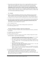
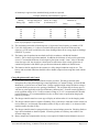
Sri Lanka: Renewable Energy for Rural Economic Development Project
SPECIFICATIONS FOR SOLAR HOME SYSTEMS
(Revised 30 August 2002)
Packaged Solar Home System Hardware Specifications
1. A solar home system (SHS) is intended to provide the user with a convenient means of supplying
power for small electrical loads such as lights, black and white TV and radio/cassette players. A
typical SHS of 30 Wp or higher capacity will provide power for at least three 12 V DC
fluorescent light fixtures and at least one 12 V DC socket outlet for a black and white 14 inch TV
or similar appliance for more than three hours a day. For systems less than 30 Wp capacity the 12
V DC outlet shall be optional. Additional 12 V DC light fixtures, 12 V DC or lower voltage
socket outlets or a DC/AC inverter may be supplied as options. Each SHS will consist of one or
more photovoltaic (PV) modules with an output of 10 Wp or more charging a 12 V DC lead-acid
battery, along with light fixtures, related electronic and electrical components and mounting
hardware. The batteries, charge controller, low voltage disconnect and associated components
will be located in sturdy enclosure(s). Examples of SHS PV module sizes and typical service
levels provided with five peak sunlight hours per day are shown below:
SHS
10 Wp
30 Wp
60 Wp
Useful energy
3 Ah/day
9 Ah/day
18 Ah/day
Typical service levels
2½ hours per day for three 5W lights
3 hours per day for three 8W lights and a 12W TV
4 hours per day for five 8W lights and a 12W TV
Note: These are representative levels of service assuming 10% module derating and 20% battery round-trip Wh
losses. Actual operating hours per day will vary depending on the number and wattage of the lights and other
appliances switched on at any given time and peak hours of sunlight available on any given day.
2. The SHS components shall be packaged to provide convenient installation at a remote customer
home site by a supplier-trained technician. The system will be constructed such that a user can
perform routine maintenance such as adding battery water and replacing light bulbs and fuses, and
a technician can easily perform system diagnostics or replace components.
3. The supplier/dealer will provide the most appropriate system integration, components, assembly
and packaging that meet all the specifications in Annex 1 - Solar Home System Requirements.
The specifications of the SHS should be summarised in Annex 2 - Solar Home System
Specification Sheet along with the required test certificates (see para 4). Any exceptions and
variations to the specifications must be explicitly stated the section titled Exceptions and
Variations in Annex 2. The scope and reasons for each listed exception and variation must be
fully explained with supporting data.
4. Products to be financed in the International Development Association (IDA) and Global
Environment Facility (GEF)-assisted Renewable Energy for Rural Economic Development
(RERED) Project must have a type-test certificate from a testing and certification organisation
acceptable to the Government of Sri Lanka and the World Bank stating that the Solar Home
System meets or exceeds the specifications given in Annex 1. Organisations accredited according
to ISO 25 or equivalent standards will be acceptable. SHS components or systems that bear the
Photovoltaic Global Approval Program (PV GAP) Mark or Seal will also be acceptable for use in
the Project without additional certification requirements. PV GAP is a Geneva-based not-forprofit international organisation dedicated to the sustained growth of global PV markets to meet
energy needs worldwide in an environmentally sound manner. (For more information see:
http://www.pvgap.org/.)
Documentation
Solar Home System Specifications – 30 August 2002
Sri Lanka Renewable Energy for Rural Economic Development Project
Page 1 of 3
5. The solar home system (SHS) supplier must provide two supporting SHS documents, namely, a
USER’S MANUAL intended for the customers (to be included with each of the packaged
systems) and a TECHNICIAN’S MANUAL FOR INSTALLATION, OPERATIONS AND
MAINTENANCE (for use by the service technicians). The latter will include the specific details
on installation, operation and maintenance. The documents must be provided in English with a
translation in Sinhalese and/or Tamil. The User’s Manual documentation should be simple and easy
to understand. Sketches and graphics should be provided to make the manual easy to understand and
use. The documentation shall include the following:
User’s Manual
6. Theory of operation of the SHS with a discussion on: battery charging by the array; functions,
battery low voltage protection and battery overcharge protection. The relationship between
energy available on a daily basis and sunlight conditions should be clearly and simply explained.
7. A description of all user interactive hardware including disconnect switches and status indicators.
8. Procedures for proper system operation, including a list of load limitations and any problem loads.
Suggested operation, including load conservation during periods of inclement weather and/or a
low voltage disconnect event. The procedures for checking that the photovoltaic array is not
shaded and how to prevent shading must be explained.
9. Any user maintenance items.
10. Procedures for emergency shut down and for extended periods of system non-use.
11. A trouble shooting guide for users.
Technician’s Manual for Installation, Operations and Maintenance
12. A complete list of all system components, with associated manufacturers literature, specifications
and warranties.
13. A complete copy of the USER’S MANUAL.
14. Complete installation instructions.
15. A recommended post-installation acceptance test procedures, including all appropriate set points
and test procedures. They will include the following:
•
Verify that the installation of the photovoltaic array with regard to position, direction,
inclination and shading avoidance will maximise energy generation.
• Ensure that the battery has received an equalisation charge just before installation.
• Use a shunt to measure the current from the array under charging conditions to verify
the array charging current. This measurement should be done under clear sky
conditions.
• Test all the loads for proper operation.
• Make system-wide voltage drop measurements in the sub-circuits to verify that
connections are within the maximum allowable voltage drop.
• Note all measurements in the installation log.
• Explain to the user the system operating principles, load management requirements,
impact of shading of the array and how to check and avoid it, user maintenance
checks and how to conduct them.
16. A recommended annual maintenance schedule, with complete maintenance instructions.
17. A detailed trouble-shooting guide referencing all the system components. This shall include
repairs and diagnostic procedures that can be done by the supplier or a qualified third party.
Repairs and procedures not to be attempted by non-electricians and/or electricians unfamiliar with
photovoltaic systems shall also be identified.
Solar Home System Specifications – 30 August 2002
Sri Lanka Renewable Energy for Rural Economic Development Project
Page 2 of 3
18. A functional block diagram, electrical single-line drawing showing the placement of all hardware
and ratings of all components and physical layout diagram.
19. Emergency shut down procedures.
SHS Specs 30Aug02.doc
Solar Home System Specifications – 30 August 2002
Sri Lanka Renewable Energy for Rural Economic Development Project
Page 3 of 3
Annex 1
SOLAR HOME SYSTEM REQUIREMENTS
General
1. (a) The supplier/dealer will provide a minimum twelve-month warranty against manufacturer’s
defects on all system-integrated parts and labour excluding fuses or end-use devices such as light
bulbs. On all major individual components, manufacturer’s warranties will be passed through to the
user. Specifically, the PV modules should be warranted against reduction of output of no more than
10 percent of rated capacity over a ten-year period. The battery, charge controller, low voltage
disconnect, switches, charge indicators, light fixtures, etc should be warranted for at least one year.
Battery end-of-life will be determined when the battery capacity down to 1.75 V/cell at 25°C drops
to less than 80 percent of the initial rated capacity.
(b) In addition, the supplier/dealer will provide a 30-day money back guarantee for users who wish
to return the SHS for whatever reason, and the suppler/dealer will refund no less than 75 percent of
the selling price of the SHS when the module, controller, battery and light fixtures are returned to the
supplier/dealer in good working condition. All warranties will start from the day the system is
accepted by the user.
2. Nominal system voltage (rated voltage) shall be 12 V DC.
3. The entire SHS must be designed and constructed such that it requires maintenance and inspection by
a technician no more frequently than once every six months.
4. The main components shall be integrated in such a way as to allow replacement (in case of failure)
with a similarly functioning component of a newer design or a different brand. This will allow for
future component evolution or variability of future component availability.
5. With the exception of the PV module(s), the supplier shall deliver the system to the user with as
many components pre-assembled and pre-wired as is feasible prior to shipment.
6. All components must have a proven and documented record of reliable performance in similar
applications. All components, including spares, will undergo full bench testing at the supplier
factory or the originating source factory with proper documentation supplied. All set point voltages
will be verified and documented with the results dated and the records maintained at the suppliers
facility.
Operating Environment
7. The entire system shall be designed and built to withstand the environmental conditions found in Sri
Lanka. For design purposes, consider that the temperature could range from zero to +40 °C and
humidity levels could reach 100 percent. The PV array and support structure must be able to
withstand wind gusts up to 100 km/hour without damage. All wiring, enclosures, and fixtures that
are mounted indoors must be resistant to high humidity, corrosion and insect and dust intrusion. Use
of corrosion resistant terminals is required. Protection of the electronic circuit boards from corrosion
by potting or applying a conformal coating is recommended.
Photovoltaic Array
8. The photovoltaic array will consist of one or more flat-plate photovoltaic modules. Each module
should comprise no less than 36 series-connected single or poly-crystalline silicon solar cells. Flat
plate thin-film modules could also be used.
Solar Home System Specifications - 30 August 2002
Sri Lanka Renewable Energy for Rural Economic Development Project
Annex 1
Page 1 of 6
9. The photovoltaic array should have a peak power output of at least 10 Wp, under Standard Test
Conditions (STC) as defined in IEC 60904-1. The peak power output for thin film modules should
be the value after light soaking.
10. Single-crystalline or poly-crystalline modules must be product tested and certified in accordance
with IEC 61215 or equivalent specifications. If thin-film photovoltaic modules are used, they must
be product tested and certified in accordance with IEC 61646 or equivalent specifications.
Crystalline or thin film modules that meet IEEE Specification 1262-1995 will also be acceptable.
11. If more than one module is used, identical models shall be used and they shall be connected in
parallel.
12. Each module must be clearly marked indicating: Manufacturer, Model Number, Serial Number, Peak
Watt Rating, Peak Current, Peak Voltage, Open Circuit Voltage and Short Circuit Current of each
module.
13. The module junction box must be sealable and moisture resistant. If the module does not have a
junction box which allows for a direct connection, then the structure will have a weather resistant
junction/combiner box attached to the support structure. This box will have a terminal strip for
connecting the parallel-wired modules.
14. The modules must be framed in such a way as to allow secure connection to the module mounting
structure.
PV Array Mounting Structure
15. The array mounting structure will hold the photovoltaic module(s). The module(s) must be mounted
to structural angle made of either aluminium or galvanised steel, secured at multiple points in order
to assure stable and secure attachment.
16. The structure must be mounted at a fixed angle and oriented to maximise the useful energy supplied
to the user during the design month (i.e., the month with the worst average daily insolation). Array
orientation must be adjustable in the field.
17. The structure will incorporate galvanised steel, aluminium or stainless steel hardware for all external
connections. These include the modules to structure, structure to pole and pole to building
attachments.
18. The modules may be roof or ground-mounted: Roof-mounting: Clearance between the PV array and
the roofing material must be at least 10 cm. Anchoring of the mounting structure must be to the
building and not to the roofing material. Ground-mounting: A metal pole must be used with the
module(s) attached at the top of the pole. The module(s) must be at least 4 metres off the ground.
The pole must be anchored in concrete at least one metre deep in the ground. The pole and
mounting structure must be sufficiently rigid to prevent twisting in the wind or if large birds alight
on the array.
Battery Storage
19. The rechargeable battery will preferably consist of one 12 V DC lead-acid battery, but no more than
two identical 12 V DC lead-acid batteries connected in parallel.
20. The 20-hour battery ampere-hour (Ah) capacity at 12 V DC, measured at 25°C, should be such that it
will permit three days of autonomy where the maximum depth of discharge is limited to 75 percent
of rated capacity. The minimum ampere-hour capacity at 12 V DC (measured at the 20-hour rate)
shall be as given in the table below. It is recommended that the battery be sized to permit five days
Solar Home System Specifications - 30 August 2002
Sri Lanka Renewable Energy for Rural Economic Development Project
Annex 1
Page 2 of 6
of autonomy in regions where extended cloudy periods are expected.
Module
Rating (Wp)
10
20
30
40
50
60
Example: Minimum lead-acid battery capacity
Minimum battery sizes (Ah) for
Average daily Ah to (Daily Ah x 3 days
autonomy of
of autonomy)/0.75
load at 12 V DC
3 days
5 days
3
6
9
12
15
18
12
24
36
48
60
72
12
24
36
48
60
72
20
40
60
80
100
120
These are based on five peak sunlight hours per day, 10% module derating and 20% battery round-trip Wh
losses (as per paragraph 1 of Specifications).
21. The maximum permissible self discharge rate is 10 percent of rated capacity per month at 25°C.
22. Cycle life of the battery (i.e., before its residual life drops below 80 percent of the rated Ah
capacity), at 25°C must exceed 200 cycles when discharged down to an average depth of discharge
(DOD) of 75 percent.
23. The battery must be production tested and certified in accordance with British Standard
60095-1:1993 or better equivalent standard. In addition, the thickness of each positive plate must
exceed 1.7 mm and the thickness of each negative plate must exceed 1.4 mm. Also, for floodedelectrolyte type cells, the electrolyte volume must be sufficient to allow at least eight weeks of
continuous operation of the SHS as per specification without the addition of distilled water.
24. The batteries shall be supplied to the customer in a fully charged condition ready for use. The
battery and associated containers should be able to handle transport down rough dirt roads without
damage.
Charge Regulator and Load Control
25. A solid-state photovoltaic charge controller must be provided. The charge controller must
incorporate one of the following charge control algorithms: (a) Constant Voltage, (b) Pulse Width
Modulated, (c) On/Off series or shunt linear. Voltage regulation (high voltage disconnect voltage)
set points should prevent excessive gassing of the battery. The set points must be factory pre-set
with the set points applicable to the specified battery characteristics. If on/off control algorithm is
used, regulation voltage of 14.4 V and a reconnect voltage of 13.4 V is recommended for flooded
lead-acid batteries. It is recommended that circuitry to allow boost or equalisation charging the
battery be provided.
26. The charge controller must have some type of display to indicate when it is in the charging mode.
27. The charge controller must be capable of handling 125% of the array’s rated short circuit current, but
not less than (a) 6 A when used with modules rated at 30 Wp or more, and (b) 3 A when used with
modules rated at less than 30 Wp.
28. The charge controller must be equipped with reverse current leakage protection. Blocking diodes or
logic derived methods are both acceptable. If blocking diodes are used they must exhibit a low
forward voltage drop.
29. Battery temperature compensation circuitry is not required if flooded lead-acid batteries are used.
Solar Home System Specifications - 30 August 2002
Sri Lanka Renewable Energy for Rural Economic Development Project
Annex 1
Page 3 of 6
However, if temperature compensation is not provided, then the set points must correspond to the
type of battery and the ambient temperature of the site where the SHS is to be used. Temperature
compensation is required if sealed lead-acid batteries are used.
30. The load must be controlled by a low voltage disconnect (LVD) device. The LVD must be capable
of handling at least 150 percent of the maximum expected continuous load (e.g., assuming all end
use devices are simultaneously on). It should be factory pre-set to disconnect and reconnect voltages
corresponding to the safe operation of the battery under ambient temperature conditions. For
example, a disconnect voltage of 11.7 V DC + 0.1 V DC and reconnect voltage of 12.9 V DC + 0.2
V DC is suitable for safe operation of lead-acid batteries used in SHS. Discharge of automotive-type
lead-acid batteries below a depth of discharge of 75% of rated capacity should not be permitted
31. Maximum current draw of the controller, when no LEDs are lit should not exceed 10mA.
32. The charge regulator/controller must be protected against damage caused by short circuit of the input
and output terminals, and reverse polarity of connections. The controller shall have electronic or
manual circuit breaker capability for load inrush currents up to 10 times rated DC current lasting less
than 10 microseconds. Such an inrush current shall not cause the load to be disconnected and shall
not cause degradation of the controller. Protective devices should disconnect the load should
currents of 10 times rated DC current last longer than 10 microseconds. Lightning induced surge
protection must be provided.
33. Some means must be provided to safely disconnect the battery and the module during servicing or
repair by a technician.
34. The model number, serial number, rated voltages and currents, set points and indicator settings
should be noted on the charge regulator case.
System Monitoring
35. Some form of a battery state-of-charge indicator must be provided on or near the controller or load
centre.
36. This device must, at a minimum, indicate when the battery condition is:
(a) Suitable to operate all loads (e.g. voltage greater than 12.5 V DC)
(b) Energy conservation required (e.g., battery voltage less than 11.9 V DC)
37. These indicators may be LEDs, or analog or digital meters.
38. The chosen device must come appropriately labelled such that the user does not have to refer to a
manual to understand the existing battery condition.
Equipment Enclosure
39. The equipment enclosure(s) will house the batteries, charge controller, charge indicators, low voltage
disconnect, and all interconnecting wiring. The enclosure(s) must not be installed in a location that
could be subject to flooding or be exposed to rain.
40. The batteries must be housed in a vented compartment. All parts of the compartment subject to
battery acid contact must be acid resistant. This compartment must be built strong enough to
accommodate the weight of the battery. This compartment must adequately support and vent wet,
lead-acid batteries. Access to the battery compartment by children must be prevented.
41. The remainder of the system components (electronics, switches etc.) must be housed in a separate
Solar Home System Specifications - 30 August 2002
Sri Lanka Renewable Energy for Rural Economic Development Project
Annex 1
Page 4 of 6
compartment or enclosures which prevents the system components being affected by battery acid
spills or fumes. The compartment or enclosure design must allow the internal electronic equipment
to operate within acceptable operating temperature limits. It must be weather, dust, and insect
resistant.
42. The enclosure must be constructed of a durable material so as to last 10 years without maintenance.
Wiring
43. Stranded and flexible insulated copper wiring must be used. Minimum acceptable cross-section of
the wire in each of the following sub-circuits is as follows:
(a) From PV module to regulator/controller: 2.5 mm2
(b) From regulator/controller to battery: 2.5 mm2
(c) From controller to loads: 1.5 mm2
44. Notwithstanding the above minimum wire size requirements, all wiring must be sized to keep line
voltage losses to less than 5% in each sub-circuit and to allow the circuit to operate within the
capacity rating of the wire.
45. All exposed wiring (with the possible exception of the module interconnects) must be in conduits or
be firmly fastened to the building structure. Wiring through roofing, walls and other structures must
be protected through the use of bushings. Wiring through roofing must form a waterproof seal.
Where the wiring is through flammable material (e.g. thatched roofs), they must be in a metal
conduit. Adequate fasteners, conduits, bushings and other installation hardware must be supplied.
46. All wiring shall be colour coded and/or labelled.
47. Field-installed wiring must be joined using terminal strips or screw connectors. Soldering or
crimping in the field must be avoided if at all possible. Wire nuts are not allowed. The rated current
carrying capacity of the joint must not be less than the circuit current rating. All connections must
be made in junction boxes. Fittings for lights, switches, and socket outlets may be used as junction
boxes where practical.
Lighting Fixtures
48. Fluorescent lamps are recommended due to their higher efficiency for area or task lighting
applications, but LED or halogen lamps may be used for special purpose applications such as night
lights. If fluorescent lamps are to be used, they must meet the following specifications.
49. Minimum operating voltage when the tube light or compact fluorescent light (CFL) will still strike
shall be less than 85% of the rated voltage.
50. Maximum continuous operating voltage without damage to the circuit must be at least 125% of the
rated voltage.
51. The minimum operating frequency should be 20 kHz and the wiring length from the inverter to the
fluorescent light bulb must be kept short to minimise radio interference.
52. The electrical waveform on the fluorescent tube terminals must be symmetrical in time to within 10
percent (i.e., 60%/40% waveform maximum difference in symmetry over the voltage range of 11.0
to 12.5 V DC at an ambient temperature of 25 degrees C).
53. The maximum crest factor (ratio of maximum peak to RMS voltage of the waveform applied to the
fluorescent tube light) shall be less than 2.
Solar Home System Specifications - 30 August 2002
Sri Lanka Renewable Energy for Rural Economic Development Project
Annex 1
Page 5 of 6
54. The input connections to the inverter should prevent the application of voltage with reverse polarity,
or the inverter should be protected against damage when the rated voltage is applied with reverse
polarity.
55. The inverter should be protected against damage by the application of voltage under open circuit
conditions (e.g., when the light bulb is removed or has failed).
56. Lenses, covers, grids etc. (if used) must be easily removable by the user for bulb replacement or for
cleaning.
57. No blackening or reduction in the lumen output by more than 10% should be observed after 1,000
ON/OFF cycles (two minutes ON and four minutes OFF is one cycle).
58. The luminous efficacy of the light, inclusive of the power requirement of the inverter, must be
either: (a) greater than 30 lumens/watt with any reflectors, lenses, covers or grids (if used) in place;
or (b) greater than 35 lumens/watt without reflectors, lenses, etc in place.
59. Light fittings must be insect proofed and corrosion and weather protected.
60. Light fittings must be marked with the manufacturer, model number, rated operating voltage, rated
current and date of manufacture or batch number.
Socket Outlet
61. A 12 V DC socket outlet for a TV or similar appliance shall be provided for systems having a
capacity of 30 Wp or more. The outlet must be rated to carry the maximum expected DC current.
The outlet must be protected from reversing the polarity of the voltage applied to the appliance. An
optional 6/9V outlet for use with radio/cassette player is recommended.
Packaging and Delivery
62. The SHS supplier/dealer must obtain the PV system equipment and components, assemble and wire
them into integrated packaged SHS in accordance with the proposed design, and deliver the
packaged SHS to the user.
63. Each system must be packaged for shipping to prevent any shipping related damage. The
supplier/dealer will be responsible for settling any shipping related damaged claims and will be
responsible for replacing damaged systems in a timely manner.
64. The modules must be packaged separately (not attached to the module support structure).
Solar Home System Specifications - 30 August 2002
Sri Lanka Renewable Energy for Rural Economic Development Project
Annex 1
Page 6 of 6
Annex 2
SOLAR HOME SYSTEM SPECIFICATION SHEET
1. Photovoltaic Module(s)
(a) Model Number ______________________________________________________
(b) Type (a-Si, crystalline Si,.etc.) __________________________________________
(c) Number of cells in series ______________________________________________
(d) Rated peak power (Pmax) __________________________________________ Wp
(e) Open circuit voltage ________________________________________________ V
(f) Short circuit Current________________________________________________ A
(g) V max __________________________________________________________ V
(h) I max ___________________________________________________________ A
(i)
NOCT _______________________________________________________ deg C
(j)
Test Certification Standard_____________________________________________
(k) Test Laboratory _____________________________________________________
(Attach I-V curve and copy of test certificate)
2. Support Structure
(a) Type_____________________________________________________ (roof/pole)
(b) Material ___________________________________________________________
3. Battery Storage
(a) Model Number ______________________________________________________
(b) Number of batteries __________________________________________________
(c) Rated voltage _____________________________________________________ V
(d) Structure and material of positive plate ___________________________________
(e) Capacity per battery at C/20 down to 1.75V/cell _________________________ Ah
(f) Self discharge rate __________________________________________ (%/month)
(g) Cycle life down to 75 percent of DOD ____________________________________
(h) Positive plate thickness ____________________________________________ mm
(i)
Negative plate thickness____________________________________________ mm
(j)
Electrolyte volume _______________________________________________ litres
(k) Certified to standard: _________________________________: _______ (Yes/No)
(Attach test certificate)
4. Charge Regulator and Load Control
(a) Model number ______________________________________________________
(b) Rated voltage _____________________________________________________ V
(c) Control algorithm____________________________________________________
(d) High voltage disconnect
(i) Voltage regulation set point (Vr) ____________________________________ V
(ii) Reconnect voltage (Vrr) __________________________________________ V
(e) Boost charging method _______________________________________________
Solar Home System Specifications – 30 August 2002
Sri Lanka Renewable Energy for Rural Economic Development Project
Annex 2
Page 1 of 4
(f) Charge indicator? ______________________________________________ Yes/No
(g) Maximum current handling capability __________________________________ A
(h) Type of current leakage protection _______________________________________
(i)
Voltage drop between module and battery terminals at controller/regulator______ V
(j)
Temperature compensation?______________________________________ Yes/No
(k) LVD maximum current handling capability ______________________________ A
(l)
LVD set points
(i) Disconnect voltage ______________________________________________ V
(ii) Reconnect voltage ______________________________________________ V
(m) Maximum current draw when no LED’s are not lit _______________________ mA
(n) Short circuit protection? _________________________________________ Yes/No
(o) Reverse polarity protection?______________________________________ Yes/No
(p) Over current protection (inrush current at 10 microseconds)? _________ Yes/No, A
(q) Lightning surge protection? ______________________________________ Yes/No
(r) Module/battery/loads disconnection method _______________________________
(Attach test certificate)
5. System Monitoring
(a) Battery state-of-charge meter/indicator?_____________________________ Yes/No
(b) Type of indicator ____________________________________________________
(c) Indications settings
Fully Charged Suitable to Use ________________________________________ V
Energy Conservation _______________________________________________ V
Other (explain) ______________________________________________________
6. Equipment Enclosure
(a) Type of battery enclosure______________________________________________
(b) Material ___________________________________________________________
(c) Type of controller housing _____________________________________________
(d) Material ___________________________________________________________
(e) Protection method against battery acid/fumes etc. ___________________________
7. Wiring
(a) Wire material type ___________________________________________________
Wire cross-sections
(b) PV module to controller ___________________________________________ mm2
(c) Controller to battery ______________________________________________ mm2
(d) Controller to loads _______________________________________________ mm2
Lengths of wiring supplied
(e) PV module to controller _____________________________________________ m
(f) Controller to battery ________________________________________________ m
(g) Controller to loads _________________________________________________ m
Solar Home System Specifications – 30 August 2002
Sri Lanka Renewable Energy for Rural Economic Development Project
Annex 2
Page 2 of 4
(h) Wiring identification method (colour coded/labelled) _______________________ .
8. Lighting Fixtures
(a) Number of fixtures ___________________________________________________
(b) Number of fluorescent lights ___________________________________________
For fluorescent lights:
(c) Model number(s) ____________________________________________________
(d) Wattage(s) _______________________________________________________ W
(e) Lumen output(s)____________________________________________________L
(f) Luminous efficacy _______________________________________________ L/W
(g) Minimum striking voltage ___________________________________________ V
(h) Maximum continuous operating voltage ________________________________ V
(i)
Operating frequency______________________________________________ kHz
(j)
Electrical waveform voltage symmetry ___________________________________
(k) Maximum crest factor ________________________________________________
(l)
Open circuit voltage protection? ________________________________ (Yes/No)
(Attach test certificate)
9. Socket Outlet
(a) 12 V DC socket outlet? _______________________________________ (Yes/No)
(b) Reverse polarity protection? ___________________________________ (Yes/No)
(c) 6 and/or 9 V outlet? __________________________________________ (Specify)
10. Other Components/Features
(a)
(b)
(c)
(d)
11. Exceptions and Variations to the Specifications Taken and Explanations
Anil Cabraal
M:\ANIL\LANKA\PVSPECS.DOC
August 28, 1996 10:50 AM
Solar Home System Specifications – 30 August 2002
Sri Lanka Renewable Energy for Rural Economic Development Project
Annex 2
Page 3 of 4
Solar Home System Specifications – 30 August 2002
Sri Lanka Renewable Energy for Rural Economic Development Project
Annex 2
Page 4 of 4