1
Cogent i.MX21 LiteKit Hardware Reference Manual - Preliminary - 1/17/2006
COGENT
”ALWAYS COMPLETE”
Cogent i.MX21 LiteKit for
Freescale MC9328MX21
Hardware Reference Manual
© 2006
Cogent Computer Systems, Inc.
PAGE 1
Cogent i.MX21 LiteKit Hardware Reference Manual - Preliminary - 1/17/2006
Table of Contents
1 Warranty ................................................................................................................................................................................................... 4
2 Overview ................................................................................................................................................................................................... 5
2.1 Introduction ....................................................................................................................................................................................... 5
2.2 Reference Documents ...................................................................................................................................................................... 5
3 On Board Devices .................................................................................................................................................................................... 6
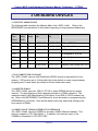
3.1 CSB535FS Address Map ................................................................................................................................................................. 6
3.2 8/16/32Mbyte STRATAFLASH......................................................................................................................................................... 6
3.3 64Mbyte SDRAM .............................................................................................................................................................................. 6
3.4 Cirrus Logic CS8900a Ethernet Controller ...................................................................................................................................... 6
3.5 ADS7846E 4-Wire Touch Controller ................................................................................................................................................ 7
3.6 Wolfson Microelectronics WM8731 I2S Codec ............................................................................................................................... 7
3.7 GPIO LED’s and Switches ............................................................................................................................................................... 7
3.8 I2C LED’s and Switches ................................................................................................................................................................... 8
3.9 3.5” QVGA TFT LCD with Touch ..................................................................................................................................................... 8
4 MC9328MX21 On-Chip I/O Devices ........................................................................................................................................................ 9
4.1 Overview ........................................................................................................................................................................................... 9
4.2 MC9328MX21 Chip Selects ............................................................................................................................................................. 9
4.3 MC9328MX21 General Purpose I/O Port Pin Assignments............................................................................................................ 9
4.4 MC9328MX21 Interrupt Pin Assignments...................................................................................................................................... 16
4.5 MC9328MX21 Debug UART .......................................................................................................................................................... 17
4.6 MC9328MX21 SPI Controller ......................................................................................................................................................... 17
4.7 MC9328MX21 I2C Interface........................................................................................................................................................... 17
4.8 MC9328MX21 4-Bit SD/MMC Controller ....................................................................................................................................... 17
4.9 MC9328MX21 Compact Flash ....................................................................................................................................................... 17
4.10 MC9328MX21 USB Device Port .................................................................................................................................................. 18
4.11 TFT LCD Controller ...................................................................................................................................................................... 18
5 Power and JTAG .................................................................................................................................................................................... 19
5.1 Overview ......................................................................................................................................................................................... 19
5.2 3.3V Switching Regulator ............................................................................................................................................................... 19
5.3 Macraigor USBDemon.................................................................................................................................................................... 19
6 CSB535FS Software .............................................................................................................................................................................. 20
6.1 Overview ......................................................................................................................................................................................... 20
7 CSB535FS CPU Module Connectors, LED’s and Switches ................................................................................................................. 21
7.1 Overview ......................................................................................................................................................................................... 21
7.2 CSB535FS Expansion Connector .................................................................................................................................................. 21
7.3 CSB535FS Expansion Connectors ................................................................................................................................................ 21
7.4 CSB535FS Expansion Connector Pinouts .................................................................................................................................... 22
7.5 CSB535FS Topside Connectors, LED’s and Switches ................................................................................................................. 26
8 CSB935FS Breakout Board Connectors, LED’s and Switches ............................................................................................................ 27
8.1 Overview ......................................................................................................................................................................................... 27
8.2 CSB935FS Connectors, LED’s and Switches - Topside............................................................................................................... 27
8.3 CSB935FS Connectors, LED’s and Switches – Backside ............................................................................................................ 28
9 Micromonitor ........................................................................................................................................................................................... 29
9.1 Introduction to Micromonitor........................................................................................................................................................... 29
9.2 Micromonitor Software Memory Map ............................................................................................................................................. 29
9.3 Connecting to Micromonitor ........................................................................................................................................................... 29
9.4 Micromonitor Commands ............................................................................................................................................................... 30
9.5 Getting More Information about Micromonitor ............................................................................................................................... 30
10 i.MX21 LiteKit Schematics .................................................................................................................................................................. 31
List of Tables
Table 1 – CSB535FS Address Map............................................................................................................................................................ 6
Table 2 – MC9328MX21 Chip Select Assignments ................................................................................................................................... 9
Table 3 – MC9328MX21 GPIO Port A Pin Assignments ......................................................................................................................... 11
Table 4 – MC9328MX21 GPIO Port B Pin Assignments ......................................................................................................................... 12
Table 5 – MC9328MX21 GPIO Port C Pin Assignments ......................................................................................................................... 13
Table 6 – MC9328MX21 GPIO Port D Pin Assignments ......................................................................................................................... 14
Table 7 – MC9328MX21 GPIO Port E Pin Assignments ......................................................................................................................... 15
Table 8 – MC9328MX21 GPIO Port F Pin Assignments ......................................................................................................................... 16
Table 9 – CSB535FS/CSB925 Interrupt Pin Assignments ...................................................................................................................... 16
Table 10 – Compact Flash GPIO Assignments........................................................................................................................................ 18
Table 11 - Expansion Connector Mating Height Table ............................................................................................................................ 22
Table 12 – P1, Expansion Connector 1 Pinout ........................................................................................................................................ 24
Table 13 – P2, Expansion Connector 2 Pinout ........................................................................................................................................ 25
Table 14 – P3, Expansion Connector 3 Pinout ........................................................................................................................................ 26
PAGE 2
Cogent i.MX21 LiteKit Hardware Reference Manual - Preliminary - 1/17/2006
PAGE 3
Cogent i.MX21 LiteKit Hardware Reference Manual - Preliminary - 1/17/2006
1 WARRANTY
The enclosed product ("the Product"), a part of the Cogent Modular Architecture or
Cogent Single Board series, is warranted by Cogent Computer Systems, Inc. ("Cogent")
for a period of six months for reasonable development testing and use, all as further
described and defined below. This warranty runs solely to the individual or entity
purchasing the Product and is not transferable or assignable in any respect. This
warranty is valid only for so long as the product is used intact as shipped from Cogent.
Any attempt or effort to alter the Product, including but not limited to any attempt to
solder, desolder, unplug, replace, add or affix any part or component of or onto the
Product, other than components specifically intended for the user to plug and unplug
into appropriate sockets and/or connectors to facilitate user programming and
development, all as specifically described and authorized in the Cogent Customer
Product Users Manual, shall void this warranty in all respects. Coverage under this
warranty requires that the Product be used and stored at all times in conditions with
proper electrostatic protection necessary and appropriate for a complex electronic
device. These conditions include proper temperature, humidity, radiation, atmosphere
and voltage (standard commercial environment, 0C to +70C, <60%RH). Any Product
that has been modified without the express, prior written consent of Cogent is not
covered by this warranty. Cogent Single Board and Cogent Modular Architecture test
and bus connectors are for use with Cogent adapters only. The use or connection of
any test or bus connector, adapter or component with any device other than a Cogent
connector or adapter shall void this warranty and the warranty of all other components,
parts and modules connected to the rest of the system. Cogent shall not be responsible
for any damage to the Product as a result of a customer's use or application of circuitry
not developed or approved by Cogent for use on or in connection with the Product.
This warranty does not cover defects caused by electrical or temperature fluctuations or
from stress resulting from or caused by abuse, misuse or misapplication of the Product.
Any evidence of tampering with the serial number on the Product shall immediately void
this warranty. This Product is not intended to be used on or embedded in or otherwise
used in connection with any life sustaining or life saving product and this warranty is not
applicable nor is Cogent liable in any respect if the Product is so used. Notwithstanding
anything to the contrary herein, Cogent expressly disclaims any implied warranty of
merchantability or implied warranty of fitness for a particular purpose in connection with
the manufacture or use of the Product.
PAGE 4
Cogent i.MX21 LiteKit Hardware Reference Manual - Preliminary - 1/17/2006
2 OVERVIEW
2.1 INTRODUCTION
The i.MX21 LiteLiteKit (CSB535FS CPU Module along with the companion CSB935FS
Breakout Board) was designed and developed by Cogent Computer Systems, Inc. as a
highly integrated Freescale MC9328MX21 Development LiteKit . The major features of
the MC9328MX21 Development LiteKit are as follows:
•
•
•
•
•
•
•
•
•
•
•
•
•
200Mhz Freescale MC9328MX21 CPU with 16K I-Cache and 16K D-Cache
64Mbyte 32-Bit Wide SDRAM
8Mbyte 16-Bit Wide FLASH
Ultra-Low Power CS8900a 10Mbit Ethernet Controller (on CSB935FS)
3.5” 240x320 QVGA TFT LCD with Integrated Touch Screen (on CSB935FS)
RS-232 Buffer for Debug Serial Port (on CSB935FS)
USB Device Interface (via USB Mini-B connector on CSB935FS)
SD/MMC Controller (4-Bit) (socket on CSB935FS)
Compact Flash Interface (socket and buffers on CSB935FS)
Wolfson WM8731 Stereo Codec (on CSB935FS) with Line In, Line Out and Microphone In
ADS7846E 4-Wire Touch Controller (on CSB935FS)
On-Board Macraigor USBDemon JTAG Controller (via USB Mini-B on CSB535FS)
Standard 20-Pin JTAG Header (on CSB935FS)
2.2 REFERENCE DOCUMENTS
Refer to the following documents for more detailed information regarding the major
components of the i.MX21 LiteKit . In all cases, you should contact the manufacturer for
the latest documentation (including errata) regarding these components.
1. “Freescale® MC9328MX21 i.MX Integrated Portable System Processor”,
Reference Manual, MC9328MX21RM/D, Rev. 1.1 11/2004
2. “3V Intel StrataFLASH Memory” Datasheet, Order # 290667-006
3. Cirrus Logic “CS8900a Product Data Sheet”, Order Number DS271PP3
4. Wolfson Microelectronics WM8731/WM8731L “Portable Internet Audio Codec
with Headphone Driver and Programmable Sample Rates”, Product Data Sheet,
April 2004, Rev. 3.4
5. Texas Instruments ADS7846E “Touch Screen Controller”, Datasheet,
SBAS125G, June 2003
PAGE 5
Cogent i.MX21 LiteKit Hardware Reference Manual - Preliminary - 1/17/2006
3 ON BOARD DEVICES
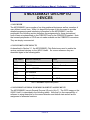
3.1 CSB535FS ADDRESS MAP
The following table describes the Address Map of the i.MX21 LiteKit . Refer to the
MC9328MX21 documentation for information regarding on-chip peripheral addressing.
CPU
Chip
Select
Chip
Select
Width
Wait
States
Address
Start
Address
End
Description
*SDCS0 32
N/A
0xC000.0000 0xC3FF.FFFF 64Mbyte SDRAM
*CS0
16
10
0xC800.0000 0xC8FF.FFFF 8Mbyte StrataFlash
*CS1
16
DTACK 0xCC00.0000 0xC1FF.FFFF CS8900a Ethernet Controller
*CS2
-
-
-
-
Pin assigned to *SDCS0
*CS3
-
-
-
-
Not Available
*CS4
-
-
-
-
Not Available
*CS5
16
8
0x1400.0000 0x17FF.FFFF Compact Flash Socket via CPLD
Table 1 – CSB535FS Address Map
3.2 8/16/32MBYTE STRATAFLASH
The i.MX21 LiteKit uses an Intel StrataFlash 28F640 device (or equivalent) for boot
memory. CS0 must be set to 16-bits width (this is the default on reset using hardware
strapping) and 10 wait states (the default is 64 wait states after reset).
3.3 64MBYTE SDRAM
The i.MX21 LiteKit uses two 16Mx16, PC100 or faster SDRAM devices for system
memory. The specifications of these devices provides for 100Mhz operation. The
maximum setting is 99.5Mhz allowing CAS Latency 2 and RAS to CAS 2 modes to be
set. Refer to the MC9328MX21 User Manual for more information on programming the
SDRAM Memory Controller. Note that the default (and only supported) setting by the
boot monitor is 60Mhz.
3.4 CIRRUS LOGIC CS8900A ETHERNET CONTROLLER
The i.MX21 LiteKit uses the CS8900a to provide a 10Mbit Ethernet Interface. This
device is mapped to CPU Chip Select 1. In addition, the interrupt output of the
CS8900a is connected to CPU GPIO PE2.
PAGE 6
Cogent i.MX21 LiteKit Hardware Reference Manual - Preliminary - 1/17/2006
CS8900a Interface Notes:
1. The CS8900a is connected to *CS2 as a 16-bit wide device with 10 wait states
minimum and DTACK enabled.
2. GPIO PE2 is connected to the CS8900a Interrupt output 0 (*IRQ0). The
CS8900a Interrupt is a low true, level output.
3.5 ADS7846E 4-WIRE TOUCH CONTROLLER
The ADS7846E provides the i.MX21 LiteKit with a 4-wire Touch Screen interface. The
CPU communicates with the ADS7846E via the standard SPI bus.
ADS7846E Interface Notes:
1. The ADS7846E is connected the MC9328MX21 using the built in SPI port.
2. GPIO PD29 (CSPI_SS0) is used as SPI Chip Select.
3. The ADS7846E interrupt output is connected to GPIO PE1. This interrupt output
is a low true, level output.
4. Software is responsible for assigning the associated GPIO signals to SPI use.
They are PD28 to PD31.
3.6 WOLFSON MICROELECTRONICS WM8731 I2S CODEC
The Wolfson WM8731 provides the i.MX21 LiteKit with a 20-Bit Audio Codec. It
supports Stereo Line in, Stereo Line out (which can also drive a headphone) and
Microphone in
WM8731 Interface Notes:
1. GPIO PC20 to PC27 must be programmed for SSI Function, I2S Mode. SSI2 is
used for the transmit (DAC) function, while SSI1 is used for the receive (ADC)
function.
2. The WM8731 uses the I2C interface for control. GPIO PD18 (SDA) and PD17
(SCL) are used for this function. Note that they can be used as bit bang I2C or
they may be programmed to the MC9328MX21 I2C Controller function.
3.7 GPIO LED’S AND SWITCHES
Two Yellow LED’s are located on the CSB535FS CPU Module along with two
pushbutton switches. The LED’s are assigned to GPIO PC14 (LED0) and PC15
(LED1), while the switches are assigned to PA22 (USR_SW0) and PA23 (USR_SW1).
A low to the LED will turn the LED on. The switches will drive the associated GPIO low
when pressed. Note that there is no de-bouncing in hardware for the switches.
PAGE 7
Cogent i.MX21 LiteKit Hardware Reference Manual - Preliminary - 1/17/2006
3.8 I2C LED’S AND SWITCHES
A Phillips PCA9554 I2C GPIO Expander is provided to interface to four red LED’s and
four pushbutton switches on the CSB935FS. The I2C address of the PCA9554 is 0x20.
Refer to the schematic for the pin assignments. CPU GPIO PE0 will go low also
whenever any one of the switches is pressed. As with the GPIO switches, there is no
hardware de-bouncing circuitry.
3.9 3.5” QVGA TFT LCD WITH TOUCH
A 3.5” Portrait Mode QVGA LCD provides the i.MX21 LiteKit with a low power,
transflective LCD display with touch overlay, similar to that used on commercial PDA’s.
This allows the user to develop graphical user interfaces for a wide variety of end
applications. Refer to the Micromonitor source code (MC9328MX21_lcd.c) for detailed
programming and setup examples. Additionally, the schematic will show the necessary
interface to this display.
PAGE 8
Cogent i.MX21 LiteKit Hardware Reference Manual - Preliminary - 1/17/2006
4 MC9328MX21 ON-CHIP I/O
DEVICES
4.1 OVERVIEW
The MC9328MX21 has a number of on-chip peripheral devices as well as a number of
user defined control lines. While it is beyond the scope of this document to provide
detailed programming and interfacing information for the MC9328MX21 on-chip
peripherals, the following section describes the assignments for these devices and
control lines as implemented on the CSB535FS and on the CSB935FS breakout. Note
that unused peripherals or GPIO are not made available on the CSB535FS connectors.
They are simply unconnected.
4.2 MC9328MX21 CHIP SELECTS
As described in Section 3.1, the MC9328MX21 Chip Selects are used to enable the
various peripheral devices on the i.MX21 LiteKit . As a cross-reference they are
described again in the following table.
Chip Select
Attached Device(s)
Notes
*CS0
StrataFLASH
Boot Device
*CS1
CS8900a
Ethernet Controller
*CS2
Used as *SDCS0
SDRAM
*CS3
Not Available
*CS4
Not Available
*CS5
Compact Flash
Via CPLD
Table 2 – MC9328MX21 Chip Select Assignments
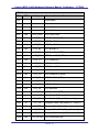
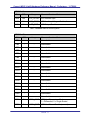
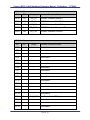
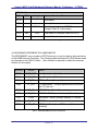
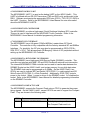
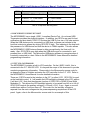
4.3 MC9328MX21 GENERAL PURPOSE I/O PORT PIN ASSIGNMENTS
The MC9328MX21 has six General Purpose I/O ports (A to F). The GPIO usage on the
i.MX21 LiteKit is described in the following tables. Note that it is the responsibility of
software to setup these bits for the correct direction and default state as well as the
assignment of alternate functions.
PAGE 9
Cogent i.MX21 LiteKit Hardware Reference Manual - Preliminary - 1/17/2006
GPIO Port A
Bit
DIR
Usage
Alternate Functions/Notes
PA1
-
-
Unavailable
PA2
-
-
Unavailable
PA3
-
-
Unavailable
PA4
-
-
Unavailable
PA5
Out
LCD_PCLK
PA6
Out
LCD_B1
LCD Blue Bit 1 (LSB)
PA7
Out
LCD_B2
LCD Blue Bit 2
PA8
Out
LCD_B3
LCD Blue Bit 3
PA9
Out
LCD_B4
LCD Blue Bit 4
PA10
Out
LCD_B5
LCD Blue Bit 5 (MSB)
PA11
Out
LCD_G0
LCD Green Bit 0 (LSB)
PA12
Out
LCD_G1
LCD Green Bit 1
PA13
Out
LCD_G2
LCD Green Bit 2
PA14
Out
LCD_G3
LCD Green Bit 3
PA15
Out
LCD_G4
LCD Green Bit 4
PA16
Out
LCD_G5
LCD Green Bit 5 (MSB)
PA17
Out
LCD_R1
LCD Red Bit 1 (LSB)
PA18
Out
LCD_R2
LCD Red Bit 2
PA19
Out
LCD_R3
LCD Red Bit 3
PA20
Out
LCD_R4
LCD Red Bit 4
PA21
Out
LCD_R5
LCD Red Bit 5 (MSB)
PA22
In
USR_SW0
User Switch 0 (0 = switch pressed)
PA23
In
USR_SW1
User Switch 1 (0 = switch pressed)
PA24
In
*CF_CD
Compact Flash Card Detect (0 = Card in)
PA25
Out
CF_RST
Compact Flash Reset (1 = reset card)
PA26
In
CF_RDY
Compact Flash Ready/Busy (1 = ready)
PA27
Out
CF_VEN
Compact Flash Voltage Enable (1 = on)
PA28
Out
LCD Pixel Clock
LCD_HSYNC LCD Horizontal Sync
PAGE 10
Cogent i.MX21 LiteKit Hardware Reference Manual - Preliminary - 1/17/2006
GPIO Port A
Bit
DIR
Usage
Alternate Functions/Notes
PA29
Out
LCD_VSYNC
LCD Vertical Sync
PA30
Out
LCD_CONT
LCD Auxiliary Voltages Enable, 1 = on
PA31
Out
LCD_DOE
LCD Output Enable
Table 3 – MC9328MX21 GPIO Port A Pin Assignments
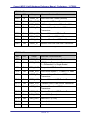
GPIO Port B
Bit
DIR
Usage
Alternate Functions/Notes
PB4
-
-
Unavailable
PB5
-
-
Unavailable
PB6
-
-
Unavailable
PB7
-
-
Unavailable
PB8
-
-
Unavailable
PB9
-
-
Unavailable
PB10
-
-
Unavailable
PB11
-
-
Unavailable
PB12
-
-
Unavailable
PB13
-
-
Unavailable
PB14
-
-
Unavailable
PB15
-
-
Unavailable
PB16
-
-
Unavailable
PB17
-
-
Unavailable
PB18
-
-
Unavailable
PB19
-
-
Unavailable
PB20
-
-
Unavailable
PB21
-
-
Unavailable
PB22
Out
USBH_MOD
PB23
Out
*USBH_PWR USB Host Power Enable (unused)
USB Host Transceiver Mode:
1 = Differential, 0 = Single Ended
PAGE 11
Cogent i.MX21 LiteKit Hardware Reference Manual - Preliminary - 1/17/2006
GPIO Port B
Bit
DIR
Usage
Alternate Functions/Notes
PB24
In
*USBH_OC
PB25
Out
PB26
Out
USBH_SPD
USB Host Speed: 1 = 12Mbit, 0 = 1Mbit
PB27
Out
*USBH_OE
Transmit Output Enable to USB Host
Transceiver
PB28
Out
USBH_VMO
Transmit Minus to USB Host Transceiver
PB29
Out
USBH_VPO
Transmit Plus to USB Host Transceiver
PB30
Out
USBH_VM
Receive Minus from USB Host Transceiver
PB31
Out
USBH_VP
Receive Plus from USB Host Transceiver
USB Host Over Current (unused)
USBH_SUSP Suspend to USB Host Transceiver
Table 4 – MC9328MX21 GPIO Port B Pin Assignments
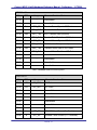
GPIO Port C
Bit
DIR
Usage
Alternate Functions/Notes
PC5
Out
USBD_EN
USB Device Transceiver Enable
PC6
Out
USBD_MOD
USB Device Transceiver Mode:
1 = Differential, 0 = Single Ended
PC7
Out
USBD_SUSP Suspend to USB Device Transceiver
PC8
Out
USBD_SPD
USB Device Speed: 1 = 12Mbit, 0 = 1Mbit
PC9
Out
*USBD_OE
Transmit Output Enable to USB Device
Transceiver
PC10
Out
USBD_VMO
Transmit Minus to USB Device Transceiver
PC11
Out
USBD_VPO
Transmit Plus to USB Device Transceiver
PC12
Out
USBD_VM
Receive Minus from USB Device
Transceiver
PC13
Out
USBD_VP
Receive Plus from USB Device Transceiver
PC14
Out
*USR_LED0
User LED 0 (0 = on)
PC15
Out
*USR_LED1
User LED 1 (0 = on)
PC16
-
-
Unavailable
PC17
-
-
Unavailable
PAGE 12
Cogent i.MX21 LiteKit Hardware Reference Manual - Preliminary - 1/17/2006
GPIO Port C
Bit
DIR
Usage
Alternate Functions/Notes
PC18
-
-
Unavailable
PC19
-
-
Unavailable
PC20
Out
SSI1_FS
PC21
In
SSI1_RXD
Receive Audio Data from I2S Codec
PC22
Out
SSI1_TXD
SSI1 Transmit Data (unused)
PC23
In
SSI1_CLK
Receive Data Clock from I2S Codec
PC24
Out
SSI2_FS
Transmit Frame Sync to I2S Codec
PC25
Out
SSI2_RXD
SSI2 Receive Data (unused)
PC26
Out
SSI2_TXD
Transmit Audio Data to I2S Codec
PC27
In
SSI2_CLK
Transmit Data Clock from I2S Codec
PC28
-
-
Unavailable
PC29
-
-
Unavailable
PC30
-
-
Unavailable
PC31
-
-
Unavailable
Receive Frame Sync to I2S Codec
Table 5 – MC9328MX21 GPIO Port C Pin Assignments
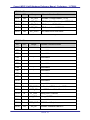
GPIO Port D
Bit
DIR
Usage
Alternate Functions/Notes
PD17
I/O
I2C_SDA
I2C Data
PD18
I/O
I2C_SCL
I2C Clock
PD19
-
-
Unavailable
PD20
-
-
Unavailable
PD21
-
-
Unavailable
PD22
-
-
Unavailable
PD23
-
-
Unavailable
PD24
-
-
Unavailable
PD25
In
*SD_CD
SD/MMC Card Detect (0 = Card in)
PD26
In
SD_WP
SD/MMC Write Protect (0 = Protected)
PAGE 13
Cogent i.MX21 LiteKit Hardware Reference Manual - Preliminary - 1/17/2006
GPIO Port D
Bit
DIR
Usage
Alternate Functions/Notes
PD27
Out
SD_VEN
SD/MMC Voltage Enable (1 = on)
PD28
Out
SPI_CS
SPI Chip Select (low true) to ADS7846E
PD29
Out
SPI_CLK
SPI Clock to ADS7846E
PD30
In
SPI_DIN
SPI Data In from ADS7846E
PD31
Out
SPI_DOUT
SPI Data Out to ADS7846E
Table 6 – MC9328MX21 GPIO Port D Pin Assignments
GPIO Port E
Bit
DIR
Usage
PE0
-
-
Unavailable
PE1
-
-
Unavailable
PE2
-
-
Unavailable
PE3
-
-
Unavailable
PE4
-
-
Unavailable
PE5
-
-
Unavailable
PE6
-
-
Unavailable
PE7
-
-
Unavailable
PE8
-
-
Unavailable
PE9
-
-
Unavailable
PE10
-
-
Unavailable
PE11
-
-
Unavailable
PE12
Out
USB_SCON
PE13
In
*USB_CD
1 = USB Device Cable Detected
PE14
In
U1_RXD
Debug UART Receive
PE15
In
U1_TXD
Debug UART Transmit
PE16
-
-
PE17
Out
PE18
I/O
*RST_OUT
SD_D0
Alternate Functions/Notes
1 = Enable USB Device for 12Mbit
Unavailable
MX21 Reset Output
SD/MMC Interface Data Bit 0
PAGE 14
Cogent i.MX21 LiteKit Hardware Reference Manual - Preliminary - 1/17/2006
GPIO Port E
Bit
DIR
Usage
Alternate Functions/Notes
PE19
I/O
SD_D1
SD/MMC Interface Data Bit 1
PE20
I/O
SD_D2
SD/MMC Interface Data Bit 2
PE21
I/O
SD_D3
SD/MMC Interface Data Bit 3
PE22
Out
SD_CMD
SD/MMC Interface Command Bit
PE23
Out
SD_CLK
SD/MMC Interface Clock Bit
Table 7 – MC9328MX21 GPIO Port E Pin Assignments
GPIO Port F
Bit
DIR
Usage
Alternate Functions/Notes
PF0
-
-
Unavailable
PF1
-
-
Unavailable
PF2
-
-
Unavailable
PF3
-
-
Unavailable
PF4
-
-
Unavailable
PF5
-
-
Unavailable
PF6
-
-
Unavailable
PF7
-
-
Unavailable
PF8
-
-
Unavailable
PF9
-
-
Unavailable
PF10
-
-
Unavailable
PF11
-
-
Unavailable
PF12
-
-
Unavailable
PF13
-
-
Unavailable
PF14
-
-
Unavailable
PF15
Out
CLK_OUT
PF16
-
-
Unavailable
PF17
-
-
Unavailable
PF18
-
-
Unavailable
Bus Clock Out (~60Mhz)
PAGE 15
Cogent i.MX21 LiteKit Hardware Reference Manual - Preliminary - 1/17/2006
GPIO Port F
Bit
DIR
Usage
Alternate Functions/Notes
PF19
-
-
Unavailable
PF20
-
-
Unavailable
PF21
In
*DTACK
PF22
Out
*CS4
PF23
-
-
Data Acknowledge from CS8900a and
Compact Flash (0 = data ready)
Chip Select 5 (Compact Flash via CPLD)
Unavailable
Table 8 – MC9328MX21 GPIO Port F Pin Assignments
4.4 MC9328MX21 INTERRUPT PIN ASSIGNMENTS
The MC9328MX21 has a number of GPIO’s that are, or can be used as interrupt inputs
to the ARM9 Interrupt Controller. The following table describes the GPIO that are used
as interrupts on the i.MX21 LiteKit . User software is required to enable the interrupt
function for any signal.
GPIO Bit
Source
Notes
PA22
*USR_SW0
User Pushbutton Switch 0
PA23
*USR_SW1
User Pushbutton Switch 1
PA24
*CF_CD
CF Card Detect (0 = card in)
PA26
CF_RDY
CF Ready/Busy – Polarity depends upon the mode
the CF card is in.
PD25
*SD_CD
SD/MMC Card Detect (0 = card in)
PE0
*I2C_INT
PCA9554 GPIO Expander Interrupt, 0 = active
PE1
*PIRQ
ADS7846E Touch Controller Interrupt, 0 = active
PE2
*E_INT
CS8900a Interrupt, 0 = active
PE13
*USB_CD
USB Cable Detect (1 = USB Device Cable In and
powered)
Table 9 – CSB535FS/CSB925 Interrupt Pin Assignments
PAGE 16
Cogent i.MX21 LiteKit Hardware Reference Manual - Preliminary - 1/17/2006
4.5 MC9328MX21 DEBUG UART
The MC9328MX21 UART 1 is used as the debug UART on the i.MX21 LiteKit . This
UART is buffered with an RS-232 Transceiver (TXD and RXD only) and brought to the
DB-9. Software must assign the appropriate GPIO pins (PE12 = TXD, PE13 = RXD) to
the UART 1 function. Refer to the MC9328MX21 Users Manual for more information
about the MC9328MX21 UARTS.
4.6 MC9328MX21 SPI CONTROLLER
The MC9328MX21 provides a high-speed, Serial Peripheral Interface (SPI) controller.
This port is used to interface with the ADS7846E Touch Controller. Refer to the
MC9328MX21 Users Manual for detailed programming information.
4.7 MC9328MX21 I2C INTERFACE
The MC9328MX21 has a full speed (100Khz/400Khz), master/slave I2C Serial
Controller. The controller is fully compatible with the industry standard I2C and SMBus
Interfaces. For simplicity, the I2C pins may also be programmed as GPIO (PD18 =
SDA, PD17 = SCL). This allows simple “Bit Banging” control of I2C peripherals without
setting up the MC9328MX21 I2C Controller
4.8 MC9328MX21 4-BIT SD/MMC CONTROLLER
The MC9328MX21 has a high-speed 4-Bit Secure Digital (SD/MMC) controller. This
controller can interface with MMC, SD and SDIO Cards with minimal host intervention.
The internal MC9328MX21 DMA controller can be used to transfer data between the
SD/MMC Socket on the i.MX21 LiteKit and system memory for very high data rates.
The SD/MMC clock can be programmed up to 20Mhz. On the i.MX21 LiteKit two
GPIO’s are used to indicate SD Card Detect (GPIO PD25, 0 = card inserted) and SD
Write Protect (GPIO PD26, 0 = Write Protected). Additionally, GPIO PD27 controls
power to the socket. When 1, power is driven to the SD/MMC socket. A 0 disables the
socket. Refer to the MC9328MX21 Users Manual for detailed programming information
on the SD/MMC Controller.
4.9 MC9328MX21 COMPACT FLASH
The MC9328MX21 supports the Compact Flash using a CPLD to generate the proper
timing signals. On the i.MX21 LiteKit , several GPIO’s are used to support the Compact
Flash. They are shown in the following table.
GPIO
Source
Notes
PA26
CSB925 - CF RDY/BSY
Polarity depends upon the mode
the Compact Flash card is in
PAGE 17
Cogent i.MX21 LiteKit Hardware Reference Manual - Preliminary - 1/17/2006
GPIO
Source
Notes
PA27
CSB925 – CF Power Enable
1 = On
PA24
CSB925 - CF Card Detect
0 = Card Present
PA25
CSB925 – CF Reset
High True
Table 10 – Compact Flash GPIO Assignments
4.10 MC9328MX21 USB DEVICE PORT
The MC9328MX21 has a single, USB1.1 compliant Device Port. An on-board USB
Transceiver provides the physical interface. In addition, two GPIO’s are used for host
notification and host detect. GPIO PC10 drives the USB D+ line via a 1.5K-ohm resistor.
When the USB device port is connected to a USB host, software can indicate to the
host that a device is present by driving GPIO PE15 high. This indicates to the host both
the presence of a USB device and that the device is 12Mbit capable. This also allows
the MC9328MX21 USB Device software to delay recognition by the Host until it is
ready. Also, GPIO PE14 goes high when the USB device port is connected to, and
powered from, a USB Host. This allows the USB device software to recognize when it
is actually connected to a host. Refer to the MC9328MX21 Users Manual for detailed
programming information.
4.11 TFT LCD CONTROLLER
The MC9328MX21 contains a built in LCD controller. On the i.MX21 LiteKit , this is
connected to the 3.5” 240x320 LCD. It is beyond the scope of this document to provide
complete programming information. Please refer to the Micromonitor source code for
an example of how to initialize and setup the LCD controller for the 3.5” LCD. Refer to
the MC9328MX21 Users Manual for more detailed information.
There are 3 GPIO’s used in the interface to the 3.5” (or other) LCD. GPIO PA2 is used
as the backlight control. A 1 will enable the LED backlight contained in the LCD, while a
0 will shut it off. Note that the alternate function of GPIO PE5 is PWM0 (Pulse Width
Modulator 0). This allows the LED backlight intensity to be varied from full on to full off.
GPIO PA30 controls the auxiliary voltages (+12V and –6.5V), if any. Again, a one will
enable them while a 0 will turn them off. The control for the auxiliary voltages is
separate from the main voltages due the power-sequencing requirement of the LCD
panel. Again, refer to the Micromonitor source code for an example of this.
PAGE 18
Cogent i.MX21 LiteKit Hardware Reference Manual - Preliminary - 1/17/2006
5 POWER AND JTAG
5.1 OVERVIEW
The i.MX21 LiteKit has a high efficiency 3.3V-switching regulator located on the CPU
Module (CSB5365FS. Additionally the module can be powered in stand-alone mode via
the USBDemon connector on the CPU Module.
5.2 3.3V SWITCHING REGULATOR
On board the CSB535FS is a high efficiency (90%+), high power, switching regulator. It
is designed to accept a wide input voltage range of +5V to +15V. It produces 4.5 Amps
of current, of which a minimum of 3 Amps is available to the CSB935FS breakout board.
3.3V Regulator Notes:
1. The optimal input voltage range for the regulator is 12V +/- 2V, which achieves
an efficiency of 90%+. Otherwise the efficiency drops to approximately 80%.
2. When powered in stand-alone mode from the USBDemon connector, the
regulator is provided with 5V +/- 10%. In this mode the maximum output current
is limited by the input power of ~2.4W x 80% = 3.3V @ 580ma.
3. Power in stand-alone or in LiteKit mode is provided via the 1.3mm power jack on
the CPU Module. Input voltage should be limited to +5V to +15V. Although the
input can be unregulated it must be DC.
4. The USBDemon circuitry uses a low drop out (LDO) regulator to power from the
input voltage. The current draw is ~50ma. At the maximum voltage (15V), the
LDO dissipates 500mw which is it’s maximum.
5.3 MACRAIGOR USBDEMON
On board the CPU Module is the Macraigor USBDemon JTAG interface. A USB Mini-B
type connector is used to interface the USBDemon to the Host computer. Refer to the
USBDemon Users Manual for detailed information on using the USBDemon JTAG
interface.
Note that the i.MX21 LiteKit contains a standard 20-pin JTAG header on the breakout
board as well. This may be used instead of the USBDemon interface. In that case, DO
NOT CONNECT the USBDemon cable and an external JTAG controller to the 20-Pin
header simultaneously.
PAGE 19
Cogent i.MX21 LiteKit Hardware Reference Manual - Preliminary - 1/17/2006
6 CSB535FS SOFTWARE
6.1 OVERVIEW
Due to the various resources contained on the CSB535FS (and CSB925), both on and
off the MC9328MX21, it is necessary to initialize a large number of MC9328MX21
registers and external devices before correct operation can begin. These values and
their proper sequencing are beyond the scope of this document. The Micromonitor
source code should be referred to as the best guide.
PAGE 20
Cogent i.MX21 LiteKit Hardware Reference Manual - Preliminary - 1/17/2006
7 CSB535FS CPU MODULE
CONNECTORS, LED’S AND SWITCHES
7.1 OVERVIEW
This section provides the locations and pinouts of the various connectors on the i.MX21
LiteKit CPU Module.
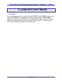
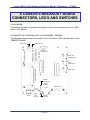
7.2 CSB535FS EXPANSION CONNECTOR
The following diagram shows the location of the Expansion Connectors and the
mounting holes on the CSB535FS. The mounting holes are .100” in diameter.
7.3 CSB535FS EXPANSION CONNECTORS
P1 and P2 are 80-Pin, low profile, SMT connectors, Hirose part number DF17(3.0)80DS-0.5V. P3 is 40-Pin, low profile, SMT connector, Hirose part number DF17(3.0)40DS-0.5V. There are two mating connector heights that can be placed on the target
board. They result in the following board-to-board and overall heights (the CSB935FS
uses the 4.0):
PAGE 21
Cogent i.MX21 LiteKit Hardware Reference Manual - Preliminary - 1/17/2006
Mating Connector
(xx = 40 or 80)
Board-Board
Height
Overall
Height
Component
Clearance
DF17(2.0)-xxDP-0.5V
5.0mm
9.0mm
1.0mm
DF17(4.0)-xxDP-0.5V
7.0mm
11.0mm
3.0mm
Table 11 - Expansion Connector Mating Height Table
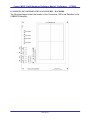
The orientation of the Target board connectors is shown in the following drawing. The
“V” in the silkscreen indicates Pin 1. 80-Pin size is shown.
80
2
79
1
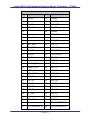
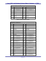
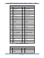
7.4 CSB535FS EXPANSION CONNECTOR PINOUTS
The following tables describe the pinouts of the four expansion connectors. The signal
name shown is the MC9328MX21 signal name unless otherwise indicated.
Expansion Connector P1
Pin
Signal
Pin
Signal
1
Ground
2
Ground
3
Ground
4
Ground
5
Ground
6
Ground
7
Ground
8
Ground
9
USB Device D-
10
USB Host D-
11
USB Device D+
12
USB Host D+
PAGE 22
Cogent i.MX21 LiteKit Hardware Reference Manual - Preliminary - 1/17/2006
Expansion Connector P1
Pin
Signal
Pin
Signal
13
Ground
14
Ground
15
Ground
16
I2C_SCL
17
SPI_DIN
18
SSI2_TXD
19
SD_VEN
20
I2C_SDA
21
-
22
Ground
23
Ground
24
SSI1_CLK
25
SSI2_CLK
26
Ground
27
Ground
28
SSI2_FS
29
SSI1_RXD
30
*SD_CD
31
SSI1_TXD
32
LCD_DOE
33
SSI1_FS
34
LCD_CONT
35
Ground
36
LCD_HSYNC
37
SPI_CLK
38
CF_RDY
39
Ground
40
*CF_CD
41
UART1_RXD
42
LCD_R4
43
*USBH_PWR
44
LCD_R1
45
*USBH_OC
46
LCD_R2
47
LCD_VSYNC
48
LCD_G0
49
LCD_G5
50
LCD_G4
51
LCD_G1
52
LCD_G2
53
LCD_R3
54
LCD_B2
55
CF_RST
56
LCD_B4
57
LCD_R5
58
LCD_B3
59
CF_VEN
60
LCD_B1
61
Ground
62
LCD_G3
63
LCD_PCLK
64
LCD_B5
65
Ground
66
CPU ADDRESS 20
67
CPU ADDRESS 19
68
CPU ADDRESS 18
PAGE 23
Cogent i.MX21 LiteKit Hardware Reference Manual - Preliminary - 1/17/2006
Expansion Connector P1
Pin
Signal
Pin
Signal
69
CPU ADDRESS 17
70
CPU ADDRESS 16
71
CPU ADDRESS 14
72
CPU ADDRESS 15
73
+3.3V
74
+3.3V
75
+3.3V
76
+3.3V
77
+3.3V
78
+3.3V
79
+3.3V
80
+3.3V
Table 12 – P1, Expansion Connector 1 Pinout
Expansion Connector P2
Pin
Signal
Pin
Signal
1
Ground
2
Ground
3
Ground
4
Ground
5
Ground
6
Ground
7
Ground
8
Ground
9
CPU CLKOUT
10
-
11
Ground
12
CPU ADDRESS 9
13
CPU ADDRESS 13
14
CPU ADDRESS 10
15
CPU ADDRESS 11
16
CPU ADDRESS 7
17
CPU ADDRESS 12
18
CPU ADDRESS 8
19
CPU DATA 15
20
CPU ADDRESS 5
21
CPU DATA 14
22
CPU ADDRESS 6
23
CPU DATA 13
24
CPU DATA 11
25
CPU ADDRESS 3
26
*EB1
27
CPU ADDRESS 4
28
CPU ADDRESS 2
29
CPU DATA 12
30
*EB0
31
*EB3
32
CPU DATA 7
33
*EB2
34
CPU DATA 9
35
*OE
36
CPU ADDRESS 1
PAGE 24
Cogent i.MX21 LiteKit Hardware Reference Manual - Preliminary - 1/17/2006
Expansion Connector P2
Pin
Signal
Pin
Signal
37
CPU DATA 10
38
CPU DATA 8
39
*DTACK
40
*CS5
41
*CS3
42
CPU ADDRESS 0
43
CPU DATA 6
44
CPU DATA 5
45
*CS1
46
CPU DATA 4
47
CPU DATA 3
48
*CS0
49
CPU DATA 0
50
CPU DATA 2
51
CPU DATA 1
52
R/*W
53
Ground
54
Ground
55
SD_CMD
56
SD_CLK
57
Ground
58
Ground
59
SD _D2
60
SD_D3
61
SD_D0
62
SD_D1
63
USB_CD
64
USB_SCON
65
UART1 TXD
66
*PIRQ (ADS7846E)
67
E_INT (CS8900a)
68
PWM0 (LED_BKL)
69
SPI_DOUT
70
SPI_CS
71
*I2C_INT (PCA9554)
72
SD_WP
73
+3.3V
74
+3.3V
75
+3.3V
76
+3.3V
77
+3.3V
78
+3.3V
79
+3.3V
80
+3.3V
Table 13 – P2, Expansion Connector 2 Pinout
Expansion Connector P3
Pin
Signal
Pin
Signal
1
Ground
2
VIN
3
Ground
4
VIN
PAGE 25
Cogent i.MX21 LiteKit Hardware Reference Manual - Preliminary - 1/17/2006
Expansion Connector P3
Pin
Signal
Pin
Signal
5
Ground
6
VIN
7
Ground
8
VIN
9
*RST_IN
10
VIN
11
*TSRT
12
VIN
13
-
14
VIN
15
TCK
16
Ground
17
TMS
18
Ground
19
TDI
20
Ground
21
TDO
22
Ground
23
*RST_OUT
24
Ground
25
BSEL0
26
Ground
27
BSEL1
28
VMAIN
29
BSEL2
30
VMAIN
31
BSEL3
32
VMAIN
33
Ground
34
VMAIN
35
Ground
36
VMAIN
37
Ground
38
VMAIN
39
Ground
40
VMAIN
Table 14 – P3, Expansion Connector 3 Pinout
7.5 CSB535FS TOPSIDE CONNECTORS, LED’S AND SWITCHES
The following diagram shows the location of the connectors, LED’s and Switches on the
CSB535FS CPU Module.
PAGE 26
Cogent i.MX21 LiteKit Hardware Reference Manual - Preliminary - 1/17/2006
8 CSB935FS BREAKOUT BOARD
CONNECTORS, LED’S AND SWITCHES
8.1 OVERVIEW
This section provides the locations and pinouts of the various connectors on the i.MX21
LiteKit CPU Module.
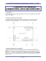
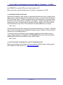
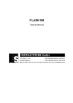
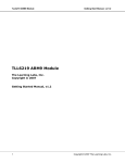
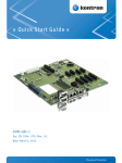
8.2 CSB935FS CONNECTORS, LED’S AND SWITCHES - TOPSIDE
The following diagram shows the location of the Connectors, LED’s and Switches on the
CSB935FS topside.
Audio Line/
Headphone Out
Ethernet
Activity LED
10Mbit
Ethernet
USB
Device
USB
Host
(not used)
Expansion Connector P2
Compact Flash Socket
Expansion
Connector P3
Expansion Connector P1
JTAG Header
Power On LED
SD/MMC Socket
Reset Switch
Ethernet
Link LED
PAGE 27
Debug Serial
Audio
Microphone In
Audio Line In
Cogent i.MX21 LiteKit Hardware Reference Manual - Preliminary - 1/17/2006
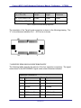
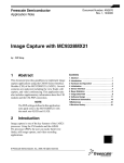
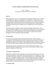
8.3 CSB935FS CONNECTORS, LED’S AND SWITCHES – BACKSIDE
The following diagram shows the location of the Connectors, LED’s and Switches on the
CSB935FS backside.
3.5” 240x320 LCD
I2C LED 0
I2C LED 1
I2C LED 2
LCD FPC Connector
I2C
I2C
I2C
I2C
Switch Switch Switch Switch
3
2
1
0
I2C LED 3
PAGE 28
Cogent i.MX21 LiteKit Hardware Reference Manual - Preliminary - 1/17/2006
9 MICROMONITOR
9.1 INTRODUCTION TO MICROMONITOR
The i.MX21 LiteKit is delivered standard with the Micromonitor boot monitor in FLASH.
Micromonitor was developed and is maintained by Ed Sutter of Lucent Technologies.
Micromonitor is an open source product and may be copied, modified and re-used
without restriction. However, neither Cogent nor Lucent is liable for any problems that
may arise during the use of Micromonitor including its use with this board.
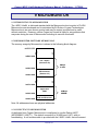
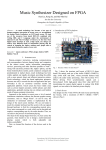
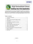
9.2 MICROMONITOR SOFTWARE MEMORY MAP
The memory usage by Micromonitor is shown in the following block diagram:
0xFFFF FFFF
0xD000 0000
TFS + Spare
(Sectors 4-63)
8Mbyte
FLASH
0xC808 0000
Micromonitor
(Sectors 0-3)
0xC800 0000
0xC700 0000
Application
RAM
0xC020 0000
0xC000 0000
64Mbyte
SDRAM
Micromonitor
BSS and Reserved
Note: All addresses shown are physical addresses.
9.3 CONNECTING TO MICROMONITOR
As delivered from Cogent, Micromonitor is configured to use the Debug UART
(MC9328MX21 UART 1). The default connection is 38,400 baud, 8-N-1, with no
handshaking. A null modem cable is provided with the i.MX21 LiteKit that will connect
PAGE 29
Cogent i.MX21 LiteKit Hardware Reference Manual - Preliminary - 1/17/2006
the CSB535FS to another DTE port such as found on a PC.
Micromonitor also uses the Ethernet port to listen for connections via UDP.
9.4 MICROMONITOR COMMANDS
Micromonitor supports a wide variety of commands that allow the user to modify and/or
read memory, download programs from Ethernet, Serial or on-board Flash File System
(TFS) and many others. Refer to the Micromonitor Users Manual for a complete listing.
Note that not all commands are available on all targets. Type the following command
(assuming you are connected using a standard terminal program) at the Micromonitor
command prompt to get a list of the commands currently enabled on your target:
umon> help
The terminal window will then display the commands installed on your target. Additional
help for each command can be displayed by typing “help xxx” where “xxx is the specific
command you are seeking help on.
You can also type the following to get information regarding the build date, memory
usage, default application load address (APPRAMBASE) and other useful information
regarding Micromonitor as installed on your i.MX21 LiteKit :
uMon> mstat
9.5 GETTING MORE INFORMATION ABOUT MICROMONITOR
Micromonitor reference information and a more advanced Micromonitor training guide
are available from Microcross, Inc. (www.microcross.com).
PAGE 30
Cogent i.MX21 LiteKit Hardware Reference Manual - Preliminary - 1/17/2006
10 I.MX21 LITEKIT SCHEMATICS
PAGE 31