1
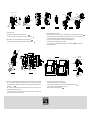
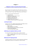
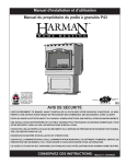
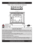
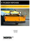
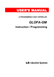
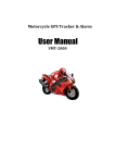
ACW125
ACW250
Installation Instruction
ROTARY HANDLE EHU ACW125 EHU ACW250 EHX ACW125 EHX ACW250
Read the instruction manual and safety precautions before use products.
This manual should be given to the person who use products and maintain them.
Fig 11
Fig 10
Before installation, wiring, operation, maintenance or inspection of the device, be sure to read the warning message carefully and ensurance
Test
proper operation.
After Handle installation, test operation before use.
Please follow the instructions, they are very important.
* In this instruction, level of dangerous are classified by 'DANGER' and 'CAUTION'.
1) Operation of Handle
Close the door and rotate the Handle to RESET position.
Rotate the Handle to ON and OFF positions to check operations.
DANGER It may result in death or serious injury.
CAUTION It may result in injury or physical damage.
It is possible that there is problem if Handle automatically returns to TRIP or OFF positions when you try to turn the circuit breaker ON.
In this case, please go the Handle and circuit breaker to chek if they are correctly installed.
DANGER
2) Opening and Closing of Panel door
Opening and closing of panel door is possible when the Handle is on 'OFF' position.
* Turn off the power before mounting, withdrawing, wiring, maintenance or inspection, Or it may be a cause for electrical shock or fire.
Door cannot be opened when Handle is on 'ON' position.
The SHAFT should be inserted to the groove of HANDLE ASS'Y smoothly.
CAUTION
1. Do not use deformed or damaged MCCB or operating handle.
2.Mounting, withdrawing , wiring, maintenance and checking should be done by authorized or certified personnel.
3. Operating handle should not be used in severe environment such as high temperature, humidity, dusty, corrosive gas, excessive vibration
and impuls.
4. Mounting should be done according to the instruction manual. Mistakes on mouting may be a cause for a MCCB or operating handle to
cause an accident such as operator injury himself.
1. Check points before use
Check the packed parts described at Table 1, Fig 1 as soon as you receive them.
Handle has three kinds of locking.
i 10.
1) HANDLE LOCK(OFF) F g
Using the padlock through the hole of LOCK PLATE, HANDLE LOCK(OFF).
Operate the handle to the 'OFF' position and pull the LOCK PLATE.
i 10.
2) HANDLE LOCK(ON) F g
Using the padlock through the hole of LOCK PLATE, HANDLE LOCK(ON).
Operate the handle to the 'ON' position and pull the LOCK PLATE.
Table 1. Parts list according to the handle type
ACW
ACW125
i1.
F g
1
3) BASE LOCK(OFF)
If you want to prevent circuit breaker operation, you can use the BASE LOCK(OFF).
There are aligned holes at lower left side of BASE ASS'Y at the 'OFF' position that can be used for locking
the circuit breaker in the OFF position.
ײ10.
ACW250
ACW400
ACW800
Parts list
Handle Type
EHU 12
EHU 16
EHU 24
EHX 12
EHX 16
EHX 24
EHU 12
EHU 16
EHU 24
EHX 12
EHX 16
EHX 24
EHU 12
EHU 16
EHU 24
EHX 12
EHX 16
EHX 24
EHU 12
EHU 16
EHU 24
EHX 12
EHX 16
EHX 24
Appendix
1. BASE ASS'Y
2. SHAFT (12 inch, 16 inch, 24 inch)
3. HANDLE ASS'Y
4. SPARE PART
Handle mounted on
4-1. M4 X L22 SCREW 2ea
Panel Door
4-2. NO.8-32 UNC-2A, L100 (EHU ACW125~EHU ACW250) :
BASE ASS'Y
SCREW 4ea
assembled
NO.10-24 UNC-2A, L100 (EHU ACW400) : SCREW 4ea
1/4"-20 UNC-2A, L140 (EHU ACW800) : SCREW 4ea
4-3. Instruction Manual
4-4. M4 X L12 SCREW 2ea
4-5. M4 NUT 2ea
5. SUPPORTER 1ea
6. 1 Gasket(Neoprene 1 sheet); or
7. 2 Gasket(VFS-1G 1 sheet, Neoprene 1 sheet)
on the circuit breaker
Connected with Shaft.
BASE ASS'Y
Nut (M4)
ACW125
°Push ±
®A¯
ACW250
ON
VFS-1R Gasket
(Red)
TRIP
Neoperen Gasket
(Black)
OFF
Supporter
Supporter
SHAFT BASE
SHAFT BASE
Screw(M4x22)
Fig 1
ACW125
Fig 2
ACW250
Fig 3
2. Assembly procedures
Fig 7
Fig 4
4) Assemble the HANDLE ASS'Y to the panel door.
1) Mount the support on BASE ASS'Y with two screws, M4 X L22 and nuts.
Fig1.
Before assembling, drill holes in the cover as shown on Fig. 6. Use two M4xL22 screws to secure the handle. Tighten to 7lb.in (0.8N.m).
At this time, the center of support should be aligned to the center of groove in SHAFT BASE.
Fig2.
You can change operating angle, by rotating the HANDLE ASS'Y position by 90 degree at same center point in clockwise direction only.
In this case, please check whether the length of handle interferes with the panel opening before changing.
2) Before installation of Handle, Push the TRIP-BUTTON of the circut breaker to power it off.
You may use the ~X types(ex;EHX16 ACW125) for IP65 protection such as appling to NEMA 4 panel.
Fig3.
Circuit breaker handle should move to the middle side (TRIP position) after pressing the BUTTON.
This handle has two Gaskets, one for NEMA12 and the other for NEMA4.
Fig4.
Fig 7.by the other gasket before
From the surface of panel, the NEMA4 gasket (Neoprene;BLACK) should be attached first, following
assembling the HANDLE ASS'Y.
Mounting Screw
1.39 (35.3)
1.10 (28)
1.38 (35)
1.18 (30)
Fig 8
®B¯
10.62 (269.8)
basing on 12 inch
3.88 (98.6)
SHAFT HOLDER
(Internal element)
Unblocked hole
10.62 (269.8)
basing on 12 inch
3.92(99.5)
BACK BASE
BAR PLATE
M4 ¿ L22 SCREW
0.433 (11)
0.433 (11)
ACW125
ACW125
Fig 5
ACW250
Fig 6
3) The BAR PLATE of ACW125/ACW250(EHU1,2/EHX1,2) should be at OFF position when you unpack it. First, lay the BASE
15.6 (396.4)
16.09 (408.7)
17.2 (437)
3.77(95.8)
4.79(121.6)
6.92(175.8)
3.81(96.7)
4.82(122.5)
6.96(176.7)
ACW250
ײ . (Fig .)
9
Fig 9
Cutting should be done on side that is not connected to HANDLE ASS'Y.
ASS'Y to align mounting holes of BASE ASS'Y with circuit breaker's mounting holes. Tighten up with mounting screws provided
Connect the Shaft after cutting and check if the door can be opened when the HANDLE is in the ‘OFF' position.
.
Fig 5
When you want to attach the new Handle on circuit breaker already mounted, remove two of four mounting screws of circuit
breaker and replace them with Handle mouting screws.
In this case, first remove the two screws from circuit breaker on diagonal side, align the Handle to the right position and
thighten two Handle mounting screws to empty mounting holes.
V LEVER
(Internal element)
5) You can cut the shaft if the length of shaft doesn't fit on your panel, .
ASS'Y on the circuit breaker so that circuit breaker¯s handle projects through the hole of BAR PLATE. Then, Pull the BASE
whith the handle.
9
15.64 (397.3)
16.13 (409.6)
17.24 (437.9)
Tighten the screw M5 X L14 located at the SHAFT BASE to secure the shaft.
The SHAFT should be inserted to the handle as shown.
Fig 9
.
Fig 8
.
Fig 6.