1
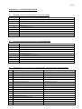
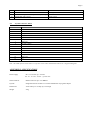
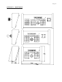
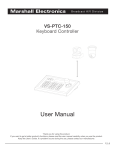
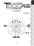
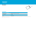
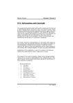
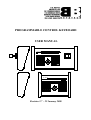
PROGRAMMABLE CONTROL KEYBOARD
USER MANUAL
P CK
R e c a l lS t o r e P T Z
P la y
S t o p V C R
F P2 T Z
F 3
FV 2C R
F 3
P CK
R e c a l lS t o r e P T Z
P la y
S t o p V C R
F P2 T Z
F 3
FV 2C R
F 3
Revision 2.7 – 22 January 2000
Page 2
1. INTRODUCTION ....................................................................................................................................................... 3
3. OPERATION ............................................................................................................................................................... 4
3.1. NUMERIC SELECTION KEYS ..................................................................................................................................... 4
3.2. SYSTEM OPERATION ................................................................................................................................................ 5
3.2.1. Camera Operation Mode................................................................................................................................. 5
3.2.2. Monitor Operation Mode.................................................................................................................................. 5
3.2.3. VCR Operation Mode ....................................................................................................................................... 5
3.2.4. Sequence Operation mode ............................................................................................................................... 6
3.2.5. Alarm Acceptance............................................................................................................................................ 6
3.2.6. User Function Keys ......................................................................................................................................... 6
4. PCK CONFIGURATION ........................................................................................................................................... 6
4.1.
4.2.
4.3.
4.4.
4.4.
SETTING THE UNIT ADDRESS ................................................................................................................................... 6
SETTING THE COMMUNICATION BAUD RATE ........................................................................................................... 7
REVERSING THE JOYSTICK Y-AXIS .......................................................................................................................... 7
SETTING FOR BALL JOYSTICK .................................................................................................................................. 7
SETTING FOR ZOOM JOYSTICK ................................................................................................................................. 7
APPENDIX A - CONNECTOR PINOUTS .................................................................................................................... 8
A.1.
A.2.
A.3.
A.4.
D9 MAIN CONNECTOR PINOUT WITH DEVICE SET IN SLAVE MODE................................................................. 8
D9 MAIN CONNECTOR PINOUT WITH DEVICE SET IN MASTER MODE ............................................................. 8
D25 MAIN CONNECTOR . THIS KEYBOARD HAS AN AUDIO AMP BUILT IN AND IS FOR AUDIO PLAYBACK ONLY. ... 8
JOYSTICK CONNECTOR PINOUT ........................................................................................................................... 9
APPENDIX B - SPECIFICATIONS ............................................................................................................................... 9
APPENDIX C - DIMENSIONS..................................................................................................................................... 10
Page 3
1. INTRODUCTION
The Programmable Control Keyboard (PCK) is a remote control keyboard for the Betatech range of video matrix
switching and control equipment. Many common functions required in controlling a medium to large sized CCTV
installation may be readily carried out from a single compact keyboard.
The major functions which have been integrated into the unit are the control of the video matrix switching equipment,
pan tilt zoom units (PTZs), video cassette recorders (VCRs), controlling the operation of sequences and the monitoring
of alarms.
The PCK also has a master mode. If the PCK address is set to zero the PCK will become a master device and generate
control data for PT telemetry receivers.
P CK
R e c a l lS t o r e P T Z
P la y
S t o p V C R
F P2 T Z
F 3
FV 2C R
F 3
FIG 1. Programmable Control Keyboard with Joystick
P CK
R e c a l lS t o r e P T Z
P la y
S t o p V C R
F P2 T Z
F 3
FV 2C R
F 3
Page 4
FIG 2. Programmable Control Keyboard Front Panel
2. CONNECTIONS
The rear panel of the PCK is as follows:
RS422 & POW ER
FIG 3. Programmable Control Keyboard with Joystick - Rear Panel Layout
P C S T Y L E J O Y S T IC K
RS422 & POW ER
FIG 4. Programmable Control Terminal Rear Panel Layout
A detailed description of the pinouts of the various connectors is provided in Appendix A.
Connection to the PCK is as follows:
•
Connect either the RS422 / RS485 to the video control equipment.
•
Connect either a transformer or a suitable DC power source.
•
Optionally plug in a standard PC type joystick.
3. OPERATION
On power up the unit will display it’s address, an introductory message, a message showing which mode of operation
has been set up and the current software revision number. The PCK will automatically test for the presence of a
joystick. If a joystick is connected to the PCK, the unit will automatically calibrate the centre position of the joystick.
It is therefore important that the joystick is left at it’s centre position while the PCK is powering up.
3.1. Numeric Selection Keys
In order to make a selection using the numeric selection keys, type in the required number using the keys “1” to “9” and
“0”. When the required value has been typed in, press the “Enter” key. The function of the “Enter” key varies
depending on the current operating mode of the system.
Errors in entering values may be corrected either with the backspace key “<-” or with the “Clear” key.
Page 5
Once a value has been selected, changing to the next or previous value may readily be accomplished by using the “Next”
and “Previous” keys respectively.
3.2. System Operation
On power up the unit will automatically enter the “Login” mode of operation. In order to log into the system the
operator must key in his / her password using the numeric keyboard. Once the value has been keyed in, the operator
must press the “Enter” key. Once the correct password has been entered the system will be placed into the “Camera
mode of operation. To prevent unauthorised control of the system the operator must press the “Login / Logout” key.
This will require the password to be entered again before any system control operation may be carried out.
Note that when the PCK is used in conjunction with small control systems, such as the Surveillance Mate Junior, the
password function is not required. In such systems, when the PCK is in “Login” mode, pressing the “Enter” key will
allow access to the system.
To change the mode press the required mode function key:
MODE KEY
FUNCTION
Login / Logout
Awaits user login, if already logged in, logs operator out.
Cam
Selects “Camera” operation mode
Mon
Selects “Monitor” operation mode
VCR
Selects “VCR” operation mode
Seq
Selects “Sequence” operation mode
3.2.1. Camera Operation Mode
When in “Camera” mode, selecting a value by means of the numeric keypad as described in 3.1. causes the selected
camera to be switched through to the currently selected monitor. The “Next” and “Previous” keys may be used to step
forwards or backwards through the various cameras in the system.
Should the camera on the currently active monitor be equipped with pan tilt zoom (PTZ) features, then the arrow keys
may be used to control the pan and tilt. The PTZ operation modes of the lower left group of keys (the function
dependent keys) on the PCK will be activated allowing for control of lens functions and PTZ auxiliary outputs. When
used in conjunction with a Philips LDH0805 camera, the camera function keys (PTZ F1, PTZ F2 and PTZ F3) allow for
selection of the camera operating mode.
A standard PC style joystick (we recommend the “Thrustmaster Flight Control System - Mark 1”) may be attached to
the joystick port. The joystick will control the pan / tilt functions. The tophat on the joystick provides for focus and iris
control. The fire and targeting buttons may be used to zoom. The two other buttons on the joystick control the iris.
Should the PTZ unit be equipped with feedback potentiometers, then it is possible to store and recall PTZ preset
positions. To store a position move the PTZ to cover the required scene. Press the “Preset Store” button. Enter the
required preset number using the numeric keyboard and then press “Enter” to store the position. Pressing “Clear” will
abort this operation. To recall a previously stored position, press the “Preset Recall” button. Enter the required preset
using the numeric keyboard and the press “Enter” to recall the preset. Pressing “Clear” will abort this operation. To
step through successive preset positions, press the “Preset Recall” button and then cycle through positions using the
“Next” and “Previous” keys.
3.2.2. Monitor Operation Mode
In this mode of operation, the numeric keypad selects the active monitor. The left and right arrow buttons cover the
same functions as the “Previous” and “Next” buttons. The up arrow will select the next camera to the currently selected
monitor. The down arrow will select the previous camera to the currently selected monitor.
3.2.3. VCR Operation Mode
In this mode of operation, the numeric keypad selects the active VCR.
The function dependent keys cause the various functions of the VCR to be invoked.
Page 6
3.2.4. Sequence Operation mode
In this mode of operation, the numeric keypad selects the active sequence. The left and right arrow buttons cover the
same functions as the “Previous” and “Next” buttons. Pressing the up arrow key will initiate the currently selected
sequence. Pressing the down arrow key will terminate the sequence.
3.2.5. Alarm Acceptance
Alarms may optionally be set up (by the main CCTV control system) in such a way that the operator will be alerted by
an alarm tone and the flashing of the “Alarm Ack” LED. To accept an alarm the operator must press the “Alarm Ack”
key.
3.2.6. User Function Keys
During “Camera”, “Monitor”, “VCR” or “Sequence” mode of operation, pressing the function keys “User 1” to “User
4” will result in sequences being started. by the main controller. Setting up which sequence is to be started is a function
of the CCTV system main controller.
4. PCK CONFIGURATION
Various Parameters of the PCK may be configured. This allows for the setting of baud rate, unit address and reversal of
the Y axis of the attached joystick.
4.1. Setting the Unit Address
The currently selected unit address is displayed when the PCK is powered up. If there is only 1 PCK in the system, the
unit address should be set to 1. Should there be more than 1 PCK, they should be set to be at unique addresses, starting
at 1.
To change the unit address switch the unit off and while holding down the “Store” button press one of the following
buttons to set the new unit address:
Key
Unit Address
0
Master PTZ Controller
1
1
2
2
3
3
4
4
5
5
6
6
7
7
8
8
9
9
0
10
Seq
11
Menu
12
Login
13
Next
14
Prev
15
Clear
16
Note that once selected, the unit address is stored internally and will not be lost when the unit is powered down.
Page 7
4.2. Setting the Communication Baud Rate
The currently baud rate is displayed when the PCK is powered up. The baud rate should be matched to that of the video
matrix switcher. Note that the highest possible baudrate should be used for fast response. The default baud rate is 19.2
Kbaud.
To change the baud rate switch the unit off and while holding down the “Store” button press one of the following
buttons to set the new baud rate:
Key
Baud Rate
User 1
1200 Baud
User 2
9600 Baud
User 3
19.2 KBaud
User 4
57.6 Kbaud
Note that once selected, the baud rate is stored internally and will not be lost when the unit is powered down.
4.3. Reversing the Joystick Y-Axis
Some joysticks provide a reversed output for movement on the Y axis.
To reverse / normalise the Y-Axis operation of the joystick, switch the unit off and while holding down the “Store”
button press one of the following buttons to set the new joystick mode:
Key
Joystick Y-Axis
Up Arrow
Reversed
Down Arrow
Normal
Note that once selected, the joystick Y-Axis reversal is stored internally and will not be lost when the unit is powered
down.
4.4. Setting for Ball Joystick
This setting provides for ball joystick operation. Under normal circumstances it is factory set and should not require
setting.
To set for ball joystick, switch the unit off and while holding down the “Store” button press the Right Arrow to set the
new joystick mode:
Key
Joystick Y-Axis
Right Arrow
Ball Joystick
4.4. Setting for Zoom Joystick
This setting provides for zoom joystick operation. Under normal circumstances it is factory set and should not require
setting.
To set for Zoom joystick, switch the unit off and while holding down the “Store” button press both the Right and Left
Arrows to set the new joystick mode:
Key
Joystick Y-Axis
Right + Right Arrow
Zoom Joystick
Page 8
APPENDIX A - CONNECTOR PINOUTS
A.1.
D9 Main Connector Pinout with device set in SLAVE MODE
Pin Number
Pin Function
1
RS422 RX[-]
2
RS422 RX[+]
3
RS422 TX[+]
4
RS422 TX[-]
5
Communications ground
A.2.
6
AC1 or unregulated DC + power input
7
NC
8
NC
9
AC2 or unregulated DC Ground power input
D9 Main Connector Pinout with device set in MASTER MODE
Pin Number
Pin Function
1
RS422 TX[-]
2
RS422 TX[+]
3
RS422 RX[+]
4
RS422 RX[-]
5
Communications ground
6
AC1 or unregulated DC + power input
7
NC
8
NC
9
AC2 or unregulated DC Ground power input
A.3.
Pin
D25 Main connector with device set in SLAVE MODE . This keyboard has Audio functionality
Pin Function for Audio Speaker and Microphone
Usually used in AUDIO INTERCOM SYSTEMS
Pin Function for Audio Speaker function
Usually used for AUDIO MONITORING
1
PCK RS422 RX[-]
RS422 RX[-]
2
PCK RS422 RX[+]
RS422 RX[+]
3
PCK RS422 TX[+]
RS422 TX[+]
4
PCK RS422 TX[-]
RS422 TX[-]
5
PCK Communications ground
Communications ground
6
Audio ground
Audio in Hot
7
Audio in Hot
Audio ground
8
Audio in Cold
9
INTERCOM RS422 RX[-]
10
INTERCOM RS422 RX[+]
11
INTERCOM RS422 TX[+]
12
INTERCOM RS422 TX[-]
13
INTERCOM Communications ground
14
PCK Supply AC1 or unregulated DC + power input
PCK Supply AC1 or unregulated DC + power input
17
AC2 or unregulated DC Ground power input
AC2 or unregulated DC Ground power input
18
Audio ground
Page 9
19
Audio out Cold
Audio in Cold
20
Audio out Hot
Audio ground
22
INTERCOM Supply AC1 or unregulated DC+ power input
25
INTERCOM Audio Ground
A.4.
Audio ground
Joystick Connector Pinout
Pin Number
Pin Function
1
Joystick common
2
Button 1/1
3
X wiper 1
4
Joystick common
5
Joystick common
6
Y wiper 1
7
Button 2/1
8
Joystick common
9
Joystick common
10
Button ½
11
X wiper 2
12
n/c
13
Y wiper 2
14
Button 2/2
15
n/c
Note: The PCK software in Revision 1.11 operates with a either Thrustmaster Mark 1 or a Logitech Wingman.
APPENDIX B - SPECIFICATIONS
Power Supply:
DC: 9 to 30 VDC @ 5 VA max
AC: 10 – 0 to 22 – 0 VAC @ 5VA max
Serial interfaces:
RS422. Data rate up to 57.6 KBaud.
Joystick:
Integtated with unit on PCK-J or external Standard PC style games adapter
Dimensions:
30cm wide by 21 cm deep by 9.6 cm high
Weight:
2 Kg
Page 10
APPENDIX C - DIMENSIONS