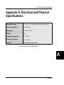
1
PK-HCS12C32
Starter Kit for
Motorola
MC9S12C32
User’s Manual
Copyright © 2003 SofTec Microsystems ®
DC00685
We want your feedback!
SofTec Microsystems is always on the look-out for new ways to improve its Products and
Services. For this reason feedback, comments, suggestions or criticisms, however small,
are always welcome.
SofTec Microsystems
E-mail (general information): [email protected]
E-mail (marketing department): [email protected]
E-mail (technical support): [email protected]
Web: http://www.softecmicro.com
Important
SofTec Microsystems reserves the right to make improvements to the PK Series of Starter Kits, their documentation and
software routines, without notice. Information in this manual is intended to be accurate and reliable. However, SofTec
Microsystems assumes no responsibility for its use; nor for any infringements of rights of third parties which may result
from its use.
SOFTEC MICROSYSTEMS WILL NOT BE LIABLE FOR DAMAGES RESULTING FROM LOSS OF DATA, PROFITS,
USE OF PRODUCTS, OR INCIDENTAL OR CONSEQUENTIAL DAMAGES, EVEN IF ADVISED OF THE POSSIBILITY
THEREOF.
Trademarks
Motorola and DigitalDNA are trademarks or registered trademarks of Motorola, Inc.
Metrowerks and CodeWarrior are trademarks or registered trademarks of Metrowerks Corp.
Microsoft and Windows are trademarks or registered trademarks of Microsoft Corporation.
PC is a registered trademark of International Business Machines Corporation.
Other products and company names listed are trademarks or trade names of their respective companies.
Written by Paolo Xausa
PK-HCS12C32 User's Manual
Contents
1. Overview
What is the PK-HCS12C32 Starter Kit?
Background Debug Module (BDM)
PK-HCS12C32 Board Layout
CodeWarrior Integrated Development Environment
Recommended Reading
Software Upgrades
2. Getting Started
PK-HCS12C32 Components
Host System Requirements
Installing the Software
Installing Metrowerks CodeWarrior IDE
Installing SofTec Microsystems Additional Components
Installing the Hardware
Application Tutorial
Additional Examples
5
5
6
7
8
9
9
11
11
11
12
12
12
13
13
17
3. Hardware Features
19
Introduction
MCU Section
USB to BDM Interface
Demo Section
Prototype Area
19
19
20
20
21
4. Debugging Features
Creating Your Own Application
Using the Project Wizard to Create Your Application Skeleton
Starting your first Debugging Session
Using Existing Projects with PK-HCS12C32
Breakpoints and Trace
23
23
23
24
25
27
Contents
Notes and Tips
Entering Debug Session with CodeWarrior
Reading Peripheral Status
Breakpoints and BGND Instruction
STOP Assembly Instruction
WAIT Assembly Instruction
Microcontroller Peripheral Running when Execution is Stopped
Real-Time Memory Update
PLL Usage
Hardware Breakpoints and Software Breakpoints
Advanced Debugging Features
DataBlaze Programming Utility
DataBlaze Notes
5. Troubleshooting
Common Problems and Solutions
Communication Can’t Be Established with PK-HCS12C32
Stepping Execution is Slow
Getting Technical Support
Appendix A. Electrical and Physical Specifications
28
28
28
28
29
29
29
29
29
30
30
31
32
35
35
35
36
36
37
PK-HCS12C32 User's Manual
1
1. Overview
What is the PK-HCS12C32 Starter Kit?
The PK-HCS12C32 Starter Kit is an entry level tool which allows you to get started with the
Motorola MC9S12C32 microcontroller.
The main features of the MC9S12C32 microcontroller are:
§
§
§
§
§
§
§
§
§
§
§
§
§
§
High-performance 16-bit HCS12 core;
32 KB of FLASH memory;
2 KB of RAM;
An asynchronous serial communications interface (SCI);
A serial peripheral interface (SPI);
8-channel, 16-bit timer module (TIM);
6-channel, 8-bit Pulse Width Modulator (PWM);
8-channel, 10-bit Analog-to-Digital converter (ADC);
A CAN 2.0 A, B software compatible module (MSCAN);
Clock Reset Generator Module (CRG);
25 MHz bus speed;
Input voltage range from 2.97 V to 5.5 V;
Single-wire background debug mode (BDM);
Enhanced Debug 12 Module, including breakpoints and change-of-flow trace buffer
(DBG12).
The PK-HCS12C32 Starter Kit has been designed for the evaluation of the MC9S12C32
microcontroller and the debugging of small user applications.
The PK-HCS12C32 Starter Kit takes advantage of the Metrowerks CodeWarrior Integrated
Development Environment (which groups an Editor, Assembler, C Compiler and Debugger)
and the Motorola BDM interface, which allows the download and debug of the user
application into the microcontroller’s FLASH memory.
Page 5
1. Overview
1
Together with CodeWarrior, PK-HCS12C32 provides you with everything you need to write,
compile, download, in-circuit emulate and debug user code. Full-speed program execution
allows you to perform hardware and software testing in real time. PK-HCS12C32 is
connected to the host PC through a USB port. A prototyping area allows you to wire your
own small application.
PK-HCS12C32 offers you the following benefits:
§
§
§
§
§
§
Real-time code execution;
In-circuit debugging;
In-system programming and debugging through a BDM-compatible interface;
Demo area with push-buttons, potentiometer and user LEDs;
Prototyping area;
Metrowerks CodeWarrior IDE (the same user interface of all Motorola tools), with editor,
assembler, C compiler and debugger.
Note: the PK-HCS12C32 starter kit has been designed for evaluation purposes only. Even
though it has full-feature debugging options, its main limitations are:
§
The target microcontroller is fixed (soldered to the board).
§
The data transfer rate (PC to target and target to PC) is slow. This results in high
programming times.
For serious debugging, we suggest you to switch to the SofTec Microsystems inDARTHCS12 Series of debugging/programming tools.
Background Debug Module (BDM)
All MCUs in the HCS12 family contain a single-wire background debug interface which
supports in-circuit programming of on-chip non-volatile memory and sophisticated nonintrusive debug capabilities. This system does not interfere with normal application
Page 6
PK-HCS12C32 User's Manual
resources. It does not use any user memory or locations in the memory map and does not
share any on-chip peripherals. The background debug module (BDM) uses a single-wire
communication interface to allow non-intrusive access to target system memory and
registers.
PK-HCS12C32 features a USB-to-BDM circuitry which allows the host PC to communicate
to the microcontroller through a standard USB cable.
PK-HCS12C32 Board Layout
The PK-HCS12C32 board has the following hardware features:
1. A “USB to BDM Interface” section. It contains the circuitry needed to electrically and
logically translate BDM-like commands sent by the host PC through the USB cable to
the BDM interface of the microcontroller. The PK-HCS12C32 board is powered (at 5 V)
by the USB bus.
2. A “Demo” section. It features a RESET push-button, two user push-buttons, a
potentiometer and eight user LEDs.
3. A “MCU” section. It contains a soldered, 80-pin MC9S12C32 device (in QFP package)
with connectors to access the I/O pins of the microcontroller for expansion prototyping.
A 16 MHz crystal oscillator (in Colpitts configuration) is provided, and the microcontroller
is configured to work in single-chip mode (MODA = MODB = 0).
4. A “Prototype” section. You can wire your own circuit here. The prototype section
features both a standard, thru-hole area (for mounting traditional components) and a
SMD area (for soldering SMD components in SOIC package).
Page 7
1
1. Overview
1
The PK-HCS12C32 Board
CodeWarrior Integrated Development Environment
PK-HCS12C32 comes with a free version of CodeWarrior Development Studio for HC(S)12
Microcontrollers, Special Edition.
CodeWarrior Development Studio for HC(S)12 is a powerful and easy-to-use tool suite
designed to increase your software development productivity. Its Integrated Development
Environment (IDE) provides unrivaled features such as Processor Expert application design
tool, full chip simulation, Data Visualization and project manager with templates to help you
concentrate on the added value of your application.
Page 8
PK-HCS12C32 User's Manual
The comprehensive, highly visual CodeWarrior Development Studio for Motorola HC(S)12
Microcontrollers enables you to build and deploy HC(S)12 systems quickly and easily. This
tool suite provides the capabilities required by every engineer in the development cycle,
from board bring-up to firmware development to final application development.
To use the Special Edition (12 KB code-size limited), you must have a valid license key.
Without the license key the product will run in a 1 KB code-size limited demonstration mode.
To request the license key, please refer to Metrowerks website.
This documentation covers the basic setup and operation of the CodeWarrior IDE, but does
not cover all of its functions. For further information, please refer to the CodeWarrior on-line
help and on-line documentation provided.
Recommended Reading
This documentation describes how to use PK-HCS12C32 together with Metrowerks
CodeWarrior HC(S)12 IDE. Additional information can be found in the following documents:
§
§
§
PK-HCS12C32 Schematic.
Metrowerks’ Additional Documentation—Available from the CodeWarrior IDE.
Motorola HCS12 Datasheets—Include detailed information on the devices’
background debug module.
Software Upgrades
The latest version of the PK-HCS12C32 system software is always available free of charge
from our website: http://www.softecmicro.com. Metrowerks CodeWarrior upgrades can be
found at http://www.metrowerks.com.
Page 9
1
PK-HCS12C32 User's Manual
2. Getting Started
2
PK-HCS12C32 Components
The PK-HCS12C32 package includes the following items:
1.
2.
3.
4.
5.
6.
The PK-HCS12C32 evaluation board;
A USB cable;
The Metrowerks CodeWarrior HC(S)12 CD-ROM;
The SofTec Microsystems PK-HCS12C32 “System Software” CD-ROM;
A “QuickStart Tutorial” color poster;
This user’s manual.
Host System Requirements
The PK-HCS12C32 in-circuit debugger is controlled by an Integrated Development
Environment running under Windows (CodeWarrior HC(S)12). The following hardware and
software are required to run the CodeWarrior HC(S)12 user interface together with PKHCS12C32:
1. A 133-MHz (or higher) PC compatible system running Windows 98, Windows 2000 or
Windows XP;
2. 128 MB of available system RAM plus 500 MB of available hard disk space;
3. A USB port;
4. CD-ROM drive for installation.
Page 11
2. Getting Started
Installing the Software
2
Note: before to connect the PK-HCS12C32 board to the PC, it is recommended that you
install all of the required software first (see below), so that the PK-HCS12C32 USB driver
will be automatically found by Windows when you connect the board.
PK-HCS12C32 requires that both Metrowerks CodeWarrior IDE and SofTec Microsystems
PK-HCS12C32 additional components be installed in the host PC.
Note: Metrowerks CodeWarrior HC(S)12 IDE must be installed first. Please note that PKHCS12C32 only works with CodeWarrior for HC(S)12 version 3.0 or above.
Installing Metrowerks CodeWarrior IDE
To install the CodeWarrior IDE insert the CodeWarrior CD-ROM into your computer’s CDROM drive. A startup window will automatically appear. Follow the on-screen instructions.
Installing SofTec Microsystems Additional Components
The SofTec Microsystems additional components install all of the other required
components to your hard drive. These components include:
§
§
§
§
The PK-HCS12C32 USB driver;
PK-HCS12C32 software plug-in for CodeWarrior HC(S)12;
Examples;
Documentation in PDF format.
To install the SofTec Microsystems additional components insert the SofTec Microsystems
“System Software” CD-ROM into your computer’s CD-ROM drive. A startup window will
automatically appear. Choose “Install Instrument Software” from the main menu. A list of
Page 12
PK-HCS12C32 User's Manual
available software will appear. Click on the “PK-HCS12 Series Additional Components”
option. Follow the on-screen instructions.
Note: if you are installing the PK-HCS12C32 additional components on Windows 2000 or
Windows XP you must have logged in as Administrator.
Installing the Hardware
The PK-HCS12C32 board is connected through a USB port to a host PC. Connection steps
are listed below in the recommended flow order:
1. Install all the required system software as described in the previous section.
2. Insert one end of the USB cable into a free USB port.
3. Insert the other end of the USB cable into the “USB” connector on the PK-HCS12C32
board. The green “POWER” LED on the instrument should turn on. Windows will
automatically recognize the instrument and will load the appropriate USB driver.
Note: both Windows 2000 and Windows XP may issue a warning the first time PKHCS12C32 is connected to the PC. This warning is related to the fact that the USB driver
used by PK-HCS12C32 is not digitally signed by Microsoft, and Windows considers it to be
potentially malfunctioning or dangerous for the system. However, you can safely ignore the
warning, since every kind of compatibility/security test has been carried out by SofTec
Microsystems.
Application Tutorial
This section will provide a step-by-step guide on how to launch your first PK-HCS12C32
project and get started with the CodeWarrior HC(S)12 user interface.
Page 13
2
2. Getting Started
The sample application reads the position of the potentiometer (connected to the
microcontroller’s ADC peripheral) and displays this value on the LEDs.
To execute the sample application, follow the next steps:
2
1. Ensure that the PK-HCS12C32 board is connected to the PC (via the USB cable).
2. Start the CodeWarrior HC(S)12 IDE by selecting Start > Programs > Metrowerks
CodeWarrior > CW12 > CodeWarrior IDE. The CodeWarrior HC(S)12 IDE will open.
3. From the main menu, choose File > Open. Select the “adc.mcp” workspace file that is
located under the “\Program Files\Metrowerks\CodeWarrior
CW12\(CodeWarrior_Examples)\MC9S12\SofTec Microsystems\PKHCS12C32\C\Adc” directory. Click “Open”. The following window will appear.
The Project Window
4. The C code of this example is contained in the “main.c” file. Double click on it to open.
The following window will appear.
Page 14
PK-HCS12C32 User's Manual
2
The Example’s Source Code
5. From the main menu, choose Project > Debug. This will compile the source code,
generate an executable file and download it to the PK-HCS12C32 board.
6. A new debugger environment will open.
Page 15
2. Getting Started
2
Debugging Session Started
7. From the main menu, choose Run > Start/Continue. The program will be executed in
real-time. By rotating the potentiometer on the PK-HCS12C32 board, you affect the
results of the A/D conversion, and the value of each conversion is displayed on the
LEDs.
8. From the main menu, choose Run > Halt. The program execution will stop. The next
instruction to be executed is highlighted in the Source window.
Page 16
PK-HCS12C32 User's Manual
9. From the main menu, choose Run > Single Step. The instruction highlighted in the
Source window will be executed, and the program execution will be stopped
immediately after.
10. In the Source window, insert a breakpoint at the “PORTB = ATDDR0H;” instruction in
the main function. To insert the breakpoint, right-click on the “PORTB = ATDDR0H;”
line and, from the pop-up menu, select “Set Breakpoint”.
11. Rotate the potentiometer slightly. Then, from the main menu, choose Run >
Start/Continue. The application will restart from where it was previously stopped. The
application will stop at the breakpoint location as soon as the next A/D conversion is
done.
12. Issue a Single Step command (Run > Single Step). The new value of the A/D
conversion will be displayed on the LEDs.
Congratulations! You have successfully completed this tutorial! You can continue to
experiment with the CodeWarrior user interface and discover by yourself its potentialities.
For an in-depth guide of all of the user interface features, select Help > CodeWarrior Help
from the CodeWarrior HC(S)12 IDE’s main menu.
Additional Examples
Additional examples can be found under the “\Program Files\Metrowerks\CodeWarrior
CW12\(CodeWarrior_Examples)\MC9S12\SofTec Microsystems\PK-HCS12C32”
directory.
Page 17
2
PK-HCS12C32 User's Manual
3. Hardware Features
Introduction
PK-HCS12C32 is an in-circuit debugger—it programs files into the MC9S12C32
microcontroller and offers debugging features like real-time code execution, stepping, and
breakpoints. Its debugging features are achieved thanks to the microcontroller’s integrated
Background Debug Module (BDM).
The BDM peripheral communicates with the host PC board (via the “USB to BDM Interface”
circuitry) through a dedicated, single-wire line (BKGD) of the microcontroller. The same line
is also used during device programming.
Contrariwise to traditional in-circuit emulation (where the target application is executed and
emulated inside the emulator), PK-HCS12C32 uses the very same target microcontroller to
carry on in-circuit execution. This means that all microcontroller’s peripherals (timers, A/D
converters, I/O pins, etc.) are not reconstructed or simulated by an external device, but are
the very same target microcontroller’s peripherals. Moreover, the PK-HCS12C32 debugging
approach ensures that the target microcontroller’s electrical characteristics (pull-ups, lowvoltage operations, I/O thresholds, etc.) are 100% guaranteed.
MCU Section
The “MCU” section contains the target microcontroller and the additional circuitry needed for
the correct microcontroller startup. In detail:
§
§
§
§
An MC9S12C32 microcontroller, together with all necessary filter capacitors.
A 16-MHz crystal oscillator, connected to the microcontroller’s EXTAL and XTAL pins.
The microcontroller’s MODA and MODB pins are connected to VSS (via pull-down
resistors) in order to enter the single-chip mode at startup.
The microcontroller’s RESET pin is externally tied to VDD via a pull-up resistor. A pushbutton in the “Demo” section is directly connected to this pin.
Page 19
3
3. Hardware Features
§
§
The microcontroller’s XFC pin is connected to an appropriate loop filter circuitry in order
to provide PLL stability at an internal bus frequency of 24 MHz.
All microcontroller’s pins are available on the four connectors placed around the
microcontroller.
USB to BDM Interface
3
This section contains the circuitry needed to electrically and logically translate BDM-like
commands sent by the host PC through the USB cable to the BDM interface of the
microcontroller.
The USB interface is based on a Motorola MC68HC908JB16 microcontroller, which features
an on-board, low-speed USB peripheral.
The USB bus provides the power supply for the board. To protect the USB bus against short
circuits that may occur during experiments, the power supply circuitry features a 200 mA
auto-restore fuse.
Note: even though USB specifications require low-speed devices to be used only with a
captive or manufacturer-specific USB cable, we have decided to use a standard USB cable.
We therefore recommend that you use the PK-HCS12C32 board with the USB cable
provided or, if you use another USB cable, ensure that the cable length does not exceed 2
meters.
Demo Section
The “Demo” section groups push-buttons, a potentiometer, and user LEDs. In detail:
§
Eight user LEDs are connected to the microcontroller’s Port B pins. All of the
microcontroller I/O pins provide the required current to drive the low-current LEDs used
by the starter kit, so no external transistors are needed.
Page 20
PK-HCS12C32 User's Manual
§
§
§
Two user push-buttons, connected to the microcontroller’s PP0 and PP1 pins. In order
to read the status of these two push-buttons, the microcontroller’s internal pull-ups must
be enabled (through software) on these pins.
One push-button connected to the microcontroller’s RESET pin.
A potentiometer, connected to the microcontroller’s PAD00 pin. Please note that VRH
and VRL (the reference voltages for the analog-to-digital converter) are connected to 5
V and VSS, respectively.
Prototype Area
The prototype section features both a standard, thru-hole area (for mounting traditional
components) and a SMD area (for soldering SMD components in SOIC package).
Page 21
3
PK-HCS12C32 User's Manual
4. Debugging Features
Creating Your Own Application
Using the Project Wizard to Create Your Application Skeleton
CodeWarrior HC(S)12 helps you get started with your own application by including a project
wizard specific for HCS12-based SofTec Microsystems boards. To create a new PKHCS12C32 project:
1. From the main menu, select File > New.
2. A dialog box will appear. Select “HC(S)12 New Project Wizard”.
3. Follow the Project Wizard steps, making sure you select the correct microcontroller
derivative you are working with and the inDART-HCS12 board as emulator.
Page 23
4
4. Debugging Features
Note: in step 7 of the project wizard, make sure to select “inDART-HCS12 Hardware
Debugging” as the connection for your project (the PK-HCS12C32 board is based on the
SofTec Microsystems’ inDART debugging engine).
4
Starting your first Debugging Session
The first time you enter a debugging session (by selecting Project > Debug from the
CodeWarrior’s main menu) the MCU Configuration dialog box will open, asking you to select
the debugging hardware connected to the PC. Make sure that the hardware code is set to
“PK-HCS12C32”.
Page 24
PK-HCS12C32 User's Manual
The MCU Configuration Dialog Box
Using Existing Projects with PK-HCS12C32
If your project has been targeted to an emulator/simulator other than PK-HCS12C32 and
you wish to use PK-HCS12C32 as the debugger for your project, please do the following:
1. If your project has been created with a version of CodeWarrior less than 3.0, make sure
that the “target” command line option specifies the GDI target interface. To do so:
a. Open your existing project’s settings dialog box.
b. In the “Target Settings Panels” section, click on the “Build Extras” item.
c. If, in the debugger’s argument edit box, the string “-target” appears, make sure that
is set to “-target=GDI”.
2. CodeWarrior is interfaced to the PK-HCS12C32 engine through a so-called “GDI
interface”. From the CodeWarrior HC(S)12 debugger interface, select Component >
Set Target and choose “HC12” as processor and “GDI Target Interface” as target
interface.
Page 25
4
4. Debugging Features
The Set Target Dialog Box
4
3. A dialog box will appear asking you to locate the GDI DLL file needed to interface with
PK-HCS12C32. Select the SofTec_BDM12.dll file located into the \Program
Files\Metrowerks\CodeWarrior CW12\prog\ directory.
The GDI Setup Dialog Box
4. The MCU Configuration dialog box will appear allowing you to select the PK-HCS12C32
board as the hardware debugger.
Page 26
PK-HCS12C32 User's Manual
The MCU Configuration Dialog Box
5. On the CodeWarrior HC(S)12 debugger interface a new menu (inDART-HCS12) will be
created. From this menu, select Load and locate the object file your project is based on.
Breakpoints and Trace
CodeWarrior offers a variety of tools for analyzing the program flow: breakpoints (both
simple and complex), watchpoints and a trace buffer. All these features are implemented by
taking advantage of the target microcontroller’s debug peripheral.
Note: the number of available hardware breakpoints depends on the details of the debug
peripheral embedded in the specific microcontroller you are working with, and on its
settings.
Note: when setting an instruction breakpoint on a RAM location, a software breakpoint is
set (the opcode present at that location is automatically replaced by the BGND Assembly
instruction). Therefore, no hardware breakpoints are wasted.
Page 27
4
4. Debugging Features
Note: the Single Step command (in a C source code) and the Step Over and Step Out
commands (both in a C and Assembly source code) use one hardware breakpoint.
Notes and Tips
Entering Debug Session with CodeWarrior
When entering a debug session, the target microcontroller’s FLASH memory is
automatically erased, unsecured and programmed with the user application.
4
Note: when programming the microcontroller with the user application (after having
unsecured the device), CodeWarrior ignores (doesn’t program) the security bits. As a result,
when entering a debug session, the device is always unsecured, regardless of other user
settings.
Reading Peripheral Status
Care must be taken when reading some peripheral’s status/data registers, since a reading
operation may cause the clearing of flags. This may happen when the Memory window or
the Data window is open, since these windows read microcontroller’s resources during
refresh operations.
Breakpoints and BGND Instruction
The BGND Assembly instruction forces the target microcontroller to enter the Active
Background Debug mode, stopping program execution. CodeWarrior recognizes this event
as a breakpoint and updates the contents of registers, memory, etc. Successive commands
(Start/Continue, Single Step, etc.) will continue the execution of the program from the next
instruction.
Page 28
PK-HCS12C32 User's Manual
STOP Assembly Instruction
The BDM peripheral doesn’t work in STOP mode. If, on the Condition Code Register (CCR),
the S bit is set, the STOP instruction will stop all the microcontroller’s activities (and
therefore the BDM peripheral). If, on the other hand, the S bit is reset, the STOP instruction
will be executed as two NOP instructions.
WAIT Assembly Instruction
If the SYSWAI bit in the CLKSEL register has been set, the WAIT instruction will cause a
BDM communication loss. This is because the system clock is suspended in WAIT mode,
therefore stopping the BDM peripheral.
Microcontroller Peripheral Running when Execution is Stopped
When program execution is stopped, some peripherals will still run while others will stop.
Which ones stop and which ones don’t depend on the particular peripheral architecture. For
more information, please refer to the microcontroller datasheets.
In particular, to cause the COP and RTI peripherals to stop when you stop program
execution, the RSBCK in the COPCTL register must have been previously set.
Real-Time Memory Update
During program execution, it is possible to view/edit the contents of the Memory window and
Data window in real time (edit operations are only available for RAM locations and
peripheral registers). For example, it is possible to set the periodical refresh of the Memory
window contents by choosing Mode > Periodical from the pop-up menu which appears by
right-clicking on the Memory window.
PLL Usage
The host PC communicates with the microcontroller through the “USB to BDM INTERFACE”
circuitry (which features an asynchronous BDM communication to the MC9S12C32
microcontroller). The BDM communication speed depends on a clock source which, in turn,
is selected by the CLKSW bit in the Status register. If the CLKSW bit is set to 1, the BDM
communication clock source is the microcontroller’s bus frequency; if the CLKSW bit is set
to 0, the BDM communication clock source is a constant clock source (in the case of the
MC9S12C32, half the frequency of the external oscillator).
Page 29
4
4. Debugging Features
PK-HCS12C32 always sets the CLKSW bit to 0: you are therefore free to change the
microcontroller’s bus frequency through the PLL, since this will not affect the BDM
communication.
Note: PK-HCS12C32 uses the 16 MHz external oscillator as the clock source for the BDM
communication. This value is fixed by design, and cannot be changed (you cannot replace
the external oscillator).
Hardware Breakpoints and Software Breakpoints
4
A “hardware” breakpoint is set by taking advantage of the microcontroller’s integrated debug
peripheral. A hardware breakpoint doesn’t waste system resources, you can set/remove
them at any time (even during program execution), but the number of available hardware
breakpoints is limited.
A “software” breakpoint, on the other hand, does not take advantage of the microcontroller’s
integrated debug peripheral.
To set a software breakpoints, there are two possibilities: you can set a software breakpoint
in RAM or in FLASH. In both cases, an unlimited number of software breakpoints can be
set.
To set a software breakpoint in a RAM location, just insert a breakpoint to that location:
CodeWarrior will automatically replace the opcode present at that location with the BGND
Assembly instruction.
To set a software breakpoint in a FLASH location, you have to insert the BGND Assembly
instruction into your application’s source code, recompile the code and restart a debug
session. The program execution will stop as soon as the BGND instruction is fetched.
Advanced Debugging Features
The MC9S12C32 microcontroller’s built-in DBG12 module allows you to set “complex”
hardware breakpoints and to take advantage of a trace buffer.
While in debug, under the inDART-HCS12 menu you will find the “Trigger Module
Settings…” command, that opens a dedicated dialog box which allows you to handle all of
the parameters of the microcontroller’s debug peripheral.
Page 30
PK-HCS12C32 User's Manual
DataBlaze Programming Utility
A full-featured programming utility (DataBlaze) is also provided with the PK-HCS12C32
Starter Kit. To start the DataBlaze utility select Start > Programs > SofTec Microsystems
> PK-HCS12 Series > DataBlaze Programmer.
DataBlaze offers the following advanced features:
§
§
§
§
§
Code memory editing;
Blank check/erase/program/verify/read operations;
Project handling;
One-button, multiple-operations programming (“Auto” feature);
Serial numbering.
Note: due to the evaluation purposes of the PK-HCS12C32 starter kit (and therefore to the
slow data transfer rate from the PC to the target and vice versa), the DataBlaze
programming utility takes a long time to write to/read from the whole microcontroller
memory.
For serious debugging/programming, we suggest you to switch to the SofTec Microsystems
inDART-HCS12 Series of debugging/programming tools.
Page 31
4
4. Debugging Features
4
The DataBlaze User Interface
DataBlaze Notes
§
§
§
The “Mass Erase” operation always blanks the device (even if the device is protected or
secured) and “unsecures” the device (the FLASH Options/Security Byte location is
programmed with 0xFE).
The “Blank Check” operation doesn’t blank check the FLASH Options/Security Byte
location.
The “Program” operation automatically verifies the programmed data, by reading back
the programmed data and checking it against the buffer sent to the target device. The
“Verify” operation is much more secure (but slower), since it reads back the
programmed data and checks it against the data buffer present in the host PC.
Page 32
PK-HCS12C32 User's Manual
§
§
In case of verifying error, please verify the value programmed to the FLASH
Options/Security Byte location. The bit 0 of this byte is always programmed to 0, so any
attempt to program it to 1 will cause a verifying error.
In the “Auto” operation, a “Run” option is available which, if enabled, resets the
microcontroller and runs the user application at the end of programming.
4
Page 33
PK-HCS12C32 User's Manual
5. Troubleshooting
Common Problems and Solutions
This section reports some common problems that may arise during general use.
Communication Can’t Be Established with PK-HCS12C32
1. Make sure the PK-HCS12C32 starter kit is connected to the PC and powered on. PKHCS12C32 is powered by the USB connection.
2. If you connected the PK-HCS12C32 board to the PC before installing the CodeWarrior
user interface and the SofTec Microsystems Additional Components, the PKHCS12C32 USB driver may not have been correctly installed on your system.
Unplugging and replugging the USB cable is of no use, since Windows has marked the
device as “disabled”. As a consequence, CodeWarrior cannot communicate with the
PK-HCS12C32 board.
To restore the USB driver (provided both CodeWarrior and SofTec Microsystems
Additional components have been installed), perform the following steps under
Windows XP:
§
§
§
§
§
§
§
Plug the PK-HCS12C32 board to the PC.
Open the Control Panel (Start > Settings > Control Panel).
Open the “System” options.
Select the “Hardware” tab.
Click the “Device Manager” button.
The “PK-HCS12 Series Starter Kit” device will be shown with an exclamation
mark next to it. Double click on this device.
In the “General” tab, click the “Reinstall Driver” button. Follow the on-screen
instructions.
Page 35
5
5. Troubleshooting
3. Make sure you are working with the correct hardware model. To view/change the
hardware model in use, choose inDART-HCS12 > MCU Configuration from the
CodeWarrior HC(S)12 debugger’s main menu.
4. If the inDART-HCS12 menu is not present in the CodeWarrior HC(S)12 debugger’s
main menu, this is because the target has not been recognized by CodeWarrior (“No
link to Target” appears in the status bar). In this case, from the GDI menu, choose MCU
Configuration and verify that the hardware code is set correctly.
Stepping Execution is Slow
When the Memory window is open, step commands may execute slower, since the Memory
window contents need to be refreshed after every step.
Getting Technical Support
5
Technical assistance is provided free to all customers. For technical assistance,
documentation and information about products and services, please refer to your local
SofTec Microsystems partner.
SofTec Microsystems offers its customers a free technical support service at
[email protected]. Before getting in contact with us, we advise you to check that
you are working with the latest version of the PK-HCS12C32 system software (upgrades are
available free of charge at http://www.softecmicro.com). Additional resources can be found
on our HCS12 online discussion forum.
Page 36
PK-HCS12C32 User's Manual
Appendix A. Electrical and Physical
Specifications
Operating Voltage
4.75 to 5.0 V DC (provided by the USB connection)
Power Consumption
200 mA (max)
Dimensions
137 x 86 x 15 mm
Weight
55 g
Operating Temperature
0 °C to 50 °C
Storage Temperature
-20 °C to 70 °C
Humidity
90% (without condensation)
Electrical and Physical Specifications
A
Page 37