1
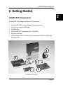
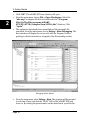
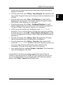
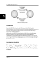
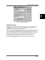
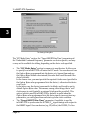
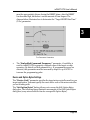
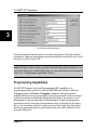
®
inDART -STX
In-Circuit
Debugger/Programmer
for STMicroelectronics
ST72F Family FLASH
Devices
User’s Manual
Copyright © 2003 SofTec Microsystems®
DC00567
SofTec Microsystems
E-mail (general information): [email protected]
E-mail (marketing department): [email protected]
E-mail (technical support): [email protected]
Web: http://www.softecmicro.com
Important
SofTec Microsystems reserves the right to make improvements to the inDART® Series
In-Circuit Debuggers, their documentation and software routines, without notice.
Information in this manual is intended to be accurate and reliable. However, SofTec
Microsystems assumes no responsibility for its use; nor for any infringements of rights of
third parties which may result from its use.
SOFTEC MICROSYSTEMS WILL NOT BE LIABLE FOR DAMAGES
RESULTING FROM LOSS OF DATA, PROFITS, USE OF PRODUCTS, OR
INCIDENTAL OR CONSEQUENTIAL DAMAGES, EVEN IF ADVISED OF THE
POSSIBILITY THEREOF.
Trademarks
inDART is a trademark of SofTec Microsystems.
ST is a trademark of STMicroelectronics.
Microsoft and Windows are trademarks or registered trademarks of Microsoft
Corporation.
PC is a registered trademark of International Business Machines Corporation.
Other products and company names listed are trademarks or trade names of their
respective companies.
Written by Paolo Xausa
inDART-STX User's Manual
Contents
1. Overview
What is inDART-STX?
ST FIVE Support
What is In-System Programming (ISP)?
Demo Boards
STVD7 Integrated Development Environment
Metrowerks (ex Hiware) and Cosmic Demo Versions
Metrowerks CodeWarrior
Recommended Reading
Software Upgrades
2. Getting Started
inDART-STX Components
Host System Requirements
Installing the Software
Installing the Hardware
Application Tutorial
3. inDART-STX Operations
inDART-STX Working Principles
Limitations
Configuring the MCU
inDART Model Settings
Device and Option Bytes Settings
Programming Capabilities
DataBlaze Programming Utility
4. Troubleshooting
Common Problems and Solutions
Communication can’t be established with inDART-STX
A communication error is returned on a program execution
command (Run, Continue, Step, etc.)
The program execution stops at the beginning of user’s code
Diagnostic Test
Getting Technical Support
5
5
5
6
8
8
8
8
9
9
11
11
12
12
13
14
19
19
20
20
21
23
24
26
27
27
27
28
28
28
29
Contents
Appendix A. Electrical and Physical Specifications
31
inDART-STX User's Manual
1
1. Overview
What is inDART-STX?
inDART-STX is a powerful entry-level tool for STMicroelectronics ST7-based
systems. inDART-STX takes advantage of STMicroelectronics STVD7
(STMicroelectronics Visual Debug) Integrated Development Environment and
the ISP (In-Circuit Programming) feature to program the FLASH memory of the
ST72F family of microcontrollers. Together with STVD7, inDART-STX provides
you with everything you need to write, compile, download, in-circuit emulate
and debug user code. Full-speed program execution allows you to perform
hardware and software testing in real time. inDART-STX is connected to the
host PC through a USB port, while the 10-pin probe of the product fits into the
target's standard ISP connector. On Design Kit packages, a full-featured
experiment board for a specific ST7 microcontroller is also included.
inDART-STX offers you the following benefits:
§
§
§
§
§
§
§
§
Real-time code execution without probes–works with all packages;
In-circuit debugging;
Built-in FLASH programmer (DataBlaze programming utility);
Supports both XFlash (EEPROM-based, single-voltage) and HDFlash
(FLASH-based, dual-voltage) devices;
Standard chip used–no bondouts, 100% electrical characteristics
guaranteed;
Working frequency up to the microcontroller’s maximum;
STMicroelectronics Visual Debug user interface (the same user interface of
all STMicroelectronics ST7 tools), with integrated C compiler and assembler
and source level and symbolic debugging;
Hardware self diagnostic test.
ST FIVE Support
The inDART-STX debugger unit also supports ST FIVE FLASH devices. To use
the inDART-STX debugger unit with ST FIVE devices, just download the
“inDART-STX for ST FIVE” software from our website
(http://www.softecmicro.com/download.html).
Page 5
1. Overview
1
What is In-System Programming (ISP)?
The ISP feature allows you to update the content of FLASH program memory
when the chip is already plugged on the application board. ISP uses the ICC (InCircuit Communication) serial protocol to interface a programming tool like
inDART. The ISP feature can be implemented with a minimum number of
added components and board area impact.
inDART-STX uses the standard, 10-pin ST7 ISP connector to program and incircuit emulate the target device. You must therefore provide such connector
(see the diagram below) on your target board.
The ST7 ISP Interface
Page 6
inDART-STX User's Manual
ISP Pin #
Pin Name
ISP Pin #
Pin Name
1
GND
2
ICCDATA
3
GND
4
ICCCLK
5
GND
6
RESET
7
VDD
8
ICCSEL/VPP
9
OSC_CLK
10
NC
1
The ST7 ISP Connector
§
§
§
§
§
§
§
ICCDATA: In-Circuit Communication input/output serial data pin.
ICCCLK: In-Circuit Communication serial clock input/output pin.
ICCSEL/VPP: ISP Entry Mode/Programming voltage. Please note that, on
some devices (e.g. ST7FLITE0), the ICCSEL/VPP line is not available.
OSC_CLK: Used to provide a device input clock signal to use when no
other clock sources are available. Depending on the target device, inDARTSTX provides a 4- or 8-MHz signal on this pin.
RESET: Device reset (input/output).
VSS: Device power supply ground.
VDD: Device power supply voltage. This voltage is provided by the target
board to inDART-STX, which in turn uses it to properly generate the
ICCDATA, ICCCLK, OSC_CLK and RESET signal voltage levels.
Note: if the RESET, ICCCLK or ICCDATA lines are used for other purposes in
the application, a serial resistor has to be implemented to avoid a conflict in
case one of the other devices forces the signal level. If these pins are used as
outputs, the serial resistors are not necessary.
Page 7
1. Overview
1
Note: as soon as inDART-STX is plugged to the target board the ICCCLK and
ICCDATA lines are not available for the application.
Demo Boards
On Design Kit packages, a full-featured, microcontroller-specific experiment
board is also included. The demo board can be used for evaluation/experiments
in the absence of a target application board.
STVD7 Integrated Development Environment
The inDART-STX user interface is based on the ST7 Visual Debug Integrated
Development Environment (STVD7). STVD7 enables programs to be executed
and stopped where desired, while viewing the memory contents. It offers the
ability to step through and examine code at the C source level and the Assembly
instruction level. You can introduce breakpoints and run or single-step the
executable, while viewing the source and observing current program values. All
registers and memory locations are accessible for both read and write
operations. This documentation covers the basic setup and operation of the
STVD7, but it does not cover all of its functions. For further information, please
refer to the STVD7 on-line help.
Metrowerks (ex Hiware) and Cosmic Demo Versions
Each of these two third-party companies have developed a C compiler for use
with ST7 microcontrollers. For more information on how to obtain a free demo
version of both compilers, please refer to the STMicroelectronics website,
http://www.stmcu.com, or go directly to the Metrowerks
(http://www.metrowerks.com) or Cosmic (http://www.cosmic-software.com)
websites.
Metrowerks CodeWarrior
As an alternative integrated development environment, you can use Metrowerks
CodeWarrior for STMicroelectronics Embedded Systems. It includes an editor,
assembler, C compiler, linker, debugger and works smoothly with inDART-STX.
Page 8
inDART-STX User's Manual
For more information about CodeWarrior for STMicroelectronics Embedded
Systems please refer to Metrowerks website (http://www.metrowerks.com).
Recommended Reading
This documentation describes how to use inDART together with the STVD7
Integrated Development Environment. Additional information can be found on
the following documents:
§
§
§
§
§
§
STVD7 Online Help—The ST7 Visual Debug online help.
AST7-LST7.PDF— This user’s guide describes how to use the
STMicroelectronics assembler, linker, formatter and librarian for the ST7
family.
ST7 FAMILY 8-BIT MCUs Programming Manual—Programming
reference containing the description of the full ST7 instruction set.
ST7 Family Data Sheets.
RELEASE.TXT—Contains notes and known problems about the STVD7
user interface.
inDART-STX for ST7 User’s Manual Addendum—Contains detailed,
device-specific information not present in this printed version. It’s available
in PDF version and can be accessed from the inDART-STX user interface.
Software Upgrades
The latest version of the inDART-STX user interface is available for free at our
download page on the web: http://www.softecmicro.com/download.html.
Page 9
1
inDART-STX User's Manual
2. Getting Started
2
inDART-STX Components
The inDART-STX package includes the following items:
1.
2.
3.
4.
5.
6.
The inDART-STX in-circuit debugger/programmer unit;
A 20-cm, 10-conductor ISP cable;
An USB cable;
The inDART-STX “System Software” CD-ROM;
This user’s manual;
A full-featured, microcontroller specific experiment board (on Design Kit
packages only).
4
5
3
2
1
6
The inDART-STX Package
Page 11
2. Getting Started
Host System Requirements
2
The inDART-STX in-circuit debugger is controlled by a PC user interface
running under Windows. The following hardware and software is required to
run the inDART-STX user interface:
1.
A PC compatible system running Windows 98, Windows Me, Windows
2000 or Windows XP;
2. 64 MB of available system RAM plus 40 MB of available hard disk space;
3. An USB port;
4. A CD-ROM drive (for installation).
Installing the Software
The inDART-STX user interface setup program is located on the SofTec
Microsystems “System Software” CD-ROM provided with the instrument. The
setup program will copy the required files (including the USB driver) to your
hard drive.
To install the inDART-STX user interface:
1.
Insert the “System Software” CD-ROM into your computer’s CD-ROM
drive.
2. A startup window should automatically appear (if the startup window
doesn’t appear automatically, manually run the Setup.exe file located on
the CD-ROM root). Choose “Install Instrument Software” from the
main menu.
3. A list of available software should appear. Click on the “Install inDARTSTX for ST7” option.
4. Follow the on-screen instructions.
Page 12
inDART-STX User's Manual
Note: the setup program will offer you the option to install the inDART-STX
plug-in for Metrowerks CodeWarrior for ST7. This option only works if you
have Metrowerks CodeWarrior for ST7 already installed in your system. By
installing the inDART-STX plug-in for Metrowerks CodeWarrior for ST7 you
will be able to use inDART-STX’s debugging capabilities from within the
CodeWarrior IDE.
Note: if you are installing the inDART-STX user interface on Windows 2000
or Windows XP you must have logged in as Administrator.
Installing the Hardware
The inDART-STX in-circuit debugger is connected through an USB port to a PC
which runs the inDART-STX user interface as explained later. Connection steps
are listed below in the recommended flow order:
1. Install the system software as described in the previous section.
2. Insert one end of the USB cable into a free PC USB port.
3. Insert the other end of the USB cable into the USB connector on the
inDART-STX board. The green “POWER” LED on the instrument should
turn on. Windows will automatically recognize the instrument and will load
the appropriate USB driver.
4. Insert one end of the ISP cable into the ISP connector on the inDART-STX
board.
5. Insert the other end of the ISP cable into the ISP connector of the demo
board or target application.
6. Turn on the power to the demo board/target application.
Please refer to the following figure to get an overview of the inDART-STX unit.
Page 13
2
2. Getting Started
2
1
2
3
1.
2.
3.
4.
4
USB Connector
ISP Connector
“POWER” LED
“BUSY” LED
The inDART-STX Unit
Note: both Windows 2000 and Windows XP may issue a warning the first
time inDART-STX is connected to the PC. This warning is related to the fact
that the USB driver used by inDART-STX is not digitally signed by Microsoft,
and Windows considers it to be potentially malfunctioning or dangerous for
the system. However, you can safely ignore the warning, since every kind of
compatibility/security test has been carried out by SofTec Microsystems.
Application Tutorial
This section will provide a step-by-step guide on how to launch your first
inDART-STX project and get started with the inDART-STX user interface.
Page 14
inDART-STX User's Manual
Note: the example provided assumes that inDART-STX is used with the IDBST7FLITE0 demo board. If you have a different demo board, some procedures
may change slightly. This tutorial is based on an Assembly example.
Additional examples in C (based on the Cosmic C compiler) are also provided.
The sample application configures the A/D peripheral to convert on the A/D
channel connected to the potentiometer and displays the results on the LEDs.
§
§
§
§
Ensure that inDART-STX is connected to the PC (via the USB cable), to the
demo board (via the ISP) connector, and that the demo board is powered
on.
Make sure that the “CLKIN SEL” jumper on the demo board selects the
“ICC” mode.
Make sure that all of the “LED ENABLE” jumpers and the
“POTENTIOMETER ENABLE” jumper are inserted.
Start the inDART-STX user interface by selecting Start > Programs >
SofTec Microsystems > inDART-STX > ST7 > STVD7 for inDARTSTX. The first time you launch the inDART-STX user interface you are
prompted to enter the toolchain paths to be used by STVD7’s integrated
development environment. Click “Yes”. The following dialog box will
appear.
The Toolchain Path Dialog Box
Page 15
2
2. Getting Started
§
§
2
§
Click “OK”. The inDART-STX user interface will open.
From the main menu, choose File > Open Workspace. Select the
“adc.wsp” workspace file that is located under the “\Program
Files\SofTec Microsystems\inDARTSTX\ST7\STVD7\Samples\Asm\LITE0\Adc” directory. Click
“Open”.
The application has already been assembled and the executable file
generated. From the main menu, choose Debug > Start Debugging. The
user interface will display the source code with the Program Counter
pointing to the first instruction, alongside of the Disassembly window.
Debugging Session Started
§
From the main menu, select Debug > Run. The program will be executed
in real-time. Please note that the “BUSY” LED on the inDART-STX unit
turns on. By rotating the potentiometer on the demo board, you affect the
Page 16
inDART-STX User's Manual
§
§
§
§
§
§
§
results of the A/D conversion, and the binary value of each conversion is
displayed on the LEDs.
From the main menu, select Debug > Stop Program. The application will
stop, and the Program Counter arrow will point to the next instruction to be
executed.
From the main menu, select View > ST7 Registers. A small window
displaying the current value of all of the ST7 registers (Program Counter,
Stack Pointer, Index Registers, etc.) will appear.
From the main menu, select View > Peripheral Registers. A small
window displaying the current status of all of the ST7 built-in peripherals
(I/O ports, Timers, A/D converter registers, etc.) will appear.
On the source code window, set a breakpoint on the “ld A, ADCDR”
instruction. To do so click on the line containing that instruction and then,
from the main menu, select Edit > Insert/Remove Breakpoint. A solid,
red circle will appear on the leftmost column indicating that the breakpoint
has been set.
From the main menu, select Debug > Run. The application will restart,
and will automatically stop at the previously set breakpoint.
From the main menu, select Debug > Step Into. This command will
execute the “ld A, ADCDR” instruction. On the ST7 Registers window, you
can see how that instruction affected the value contained on the
Accumulator. This value is the result of the A/D conversion.
Issue another Step Into command (Debug > Step Into). The Accumulator
value will be displayed on the LEDs.
Congratulations! You have successfully completed this tutorial! You can
continue to experiment with the inDART-STX user interface and discover by
your own its potentialities. For an in-depth guide of all of the user interface
features, select Help > Search from the main menu.
Page 17
2
inDART-STX User's Manual
3. inDART-STX Operations
inDART-STX Working Principles
inDART-STX is an in-circuit debugger as well as a programming tool. It
programs files into the ST72F microcontrollers and offers debugging features
like real-time code execution, stepping, and breakpoint. Its debugging features
are achieved thanks to either:
§
§
An integrated on-chip debug module (available on some devices, such as
ST7FLITE2) which allows for breakpoint handling, run/stop, etc.
A small portion of monitor code which is automatically and transparently
added to the user code and programmed into the target microcontroller.
The monitor code has been developed by SofTec Microsystems for devices
without on-chip debugging capabilities.
Both the on-chip debug module and the downloaded monitor communicate with
the host PC through a bidirectional, command-based protocol via the ICCDATA
and ICCCLK lines of the microcontroller. For this reason, the ICCDATA and
ICCCLK lines are reserved during debugging sessions. The same two lines are
also used during device programming.
Contrariwise to traditional in-circuit emulation (where the target application is
executed and emulated inside the emulator), inDART-STX uses the very same
target microcontroller to carry on in-circuit execution. This means that all
microcontroller’s peripherals (timers, A/D converters, I/O pins, etc.) are not
reconstructed or simulated by an external device, but are the very same target
microcontroller’s peripherals. Moreover, the inDART-STX debugging approach
ensures that the target microcontroller’s electrical characteristics (pull-ups, lowvoltage operations, I/O thresholds, etc.) are 100% guaranteed. The trade-off,
however, is that the target microcontroller must be properly configured and
ready to execute target applications.
Page 19
3
3. inDART-STX Operations
3
inDART-STX Working Principle
Limitations
Since inDART-STX is based on the ISP feature of the ST72F family of
microcontrollers, some on-chip resources are wasted for debugging purposes. In
particular, during debugging the ICCDATA and ICCCLK lines are always
reserved for emulation purposes.
Additionally, inDART-STX takes advantage of all of the on-chip debugging
features (if present) of the specific microcontroller under emulation.
Consequently, for each microcontroller supported by inDART-STX, there is a
series of specific limitations that have to be accounted for during the debugging
process. Please refer to the inDART-STX online user’s manual addendum for
detailed information.
Configuring the MCU
Before to start a debugging session, you must define and configure the target
device (MCU) you wish inDART-STX to emulate. The target device is defined
and configured from the MCU Configuration dialog box. To access it, select
Tools > MCU Configuration from the main menu. The following dialog box
will appear.
Page 20
inDART-STX User's Manual
3
The MCU Configuration Dialog Box
inDART Model Settings
First of all, verify that the inDART model corresponds to “inDART-STX”. The
“Settings” button then allows you to set up detailed parameters used by
inDART-STX to perform its debugging activities.
All of the inDART-STX debugging and programming capabilities rely on the ICC
(In-Circuit Communication) mode of the target device. In order to enter this
special mode (which establishes a communication channel between the target
device and inDART-STX through the ICCDATA and ICCCLK lines) and
configure it properly, a few parameters must be correctly specified.
By clicking the “Settings” button the following dialog box will appear:
Page 21
3. inDART-STX Operations
3
The Settings Dialog Box
The “ICC Mode Entry” section, the “Target RESET Rise Time” parameter and
the “Embedded Command Frequency” parameter are device-specific, and may
or may not be available for editing, depending on the device code specified.
§
§
The “ICC Mode Entry” section is common to most devices. It allows you
to specify how inDART-STX will enter the ICC mode. You can choose to use
the Option Bytes programmed into the device or to bypass them and use
the Option Bytes default value instead (the value that would be used if the
device is blank).
In the former case, you must provide the required clock source (specified in
the Option Bytes value programmed into the device)—otherwise the device
won’t work.
In the latter case, the device is assumed to be blank, and forced to use its
default Option Bytes value. This means, among other things, that a “safe”
clock source is used (typically an external clock must be provided). This
option (which is used by inDART-STX by default) is useful when the
Option Bytes value programmed into the device specify incorrect start-up
parameters; you can bypass them and start-up from a safe condition.
The “Target RESET Rise Time” parameter, if available, is used by
inDART-STX to synchronize the ICCSEL/VPP signal timings with respect to
the RESET signal. On some devices (e.g. ST72F621) the ICCSEL/VPP line
Page 22
inDART-STX User's Manual
must be appropriately driven, during the RESET phase, after the RESET
line becomes high, but before a certain amount of time elapses. The
diagram below illustrates how to determine the “Target RESET Rise Time”
(TRISE) parameter.
3
TRISE Parameter Constraints
§
The “Embedded Command Frequency” parameter, if available, is
used by inDART-STX to properly configure some of the target on-chip
resources. By default, set this parameter to 1. If programming errors are
detected, this parameter must be increased by steps of 1 up to fCPU to
increase the programming pulse.
Device and Option Bytes Settings
The “Device Code” parameter specifies the target microcontroller used in your
target application. You must specify the exact device code of the microcontroller
you are working with.
The “Set Option Bytes” button allows you to access the Edit Option Bytes
dialog box. The following figure illustrates an example of the Edit Option Bytes
dialog box (every microcontroller has its own specific Option Bytes).
Page 23
3. inDART-STX Operations
3
The Edit Option Bytes dialog box
Particular attention must be paid in correctly setting each of the Option Bytes
parameters. Improper settings may cause the target microcontroller not to work
correctly (or not to work at all).
Note: the Option Bytes values specified in the Edit Option Bytes dialog box are
used when debugging. Additionally, they are also used when programming the
device (see “Programming Capabilities” below).
Programming Capabilities
inDART-STX features In-Circuit Programming (ISP) capabilities. A
programming utility is built-in in the inDART-STX user interface. When in
Debugging mode, the Tools > Program command in the main menu is
enabled, and allows you to program the target microcontroller with your target
application code but without any debugging code (that is, the monitor is not
programmed—only the application is programmed). A typical programming
procedure is made of a series of programming steps, as indicated in the figure
below. You can choose whether to perform or not each single step. Please note
that the programming steps are performed in the exact order indicated in the
Program dialog box.
Page 24
inDART-STX User's Manual
3
The Program Dialog Box
§
§
§
§
§
§
§
Clear Read-Out Protection. Clears the Read-Out Protection bit. Check
this programming step when you are programming a device which has been
programmed with the Read-Out Protection bit set.
Erase Device. Erases the entire Code memory area.
Program FLASH Memory. Writes the application code into the Code
memory area.
Verify FLASH Memory. Verifies that the application code has been
correctly written into the Code memory.
Program Option Bytes. Programs the Option Bytes according to the
parameters specified in the Edit Option Bytes dialog box.
Set Read-Out Protection. Set the Read-Out Protection bit. Check this
programming step if you want to protect the application code from external
reading operations.
Run. After programming, resets the microcontroller and executes the
application program.
Page 25
3. inDART-STX Operations
Note: after programming the device, you will not be able to continue with the
current debugging session. To continue debugging, you must stop the current
debugging session and start a new one. This happens because the monitor has
not been programmed with the application.
3
DataBlaze Programming Utility
A standalone, full-featured programming utility (DataBlaze) is also provided
with inDART-STX. To start the DataBlaze utility select Start > Programs >
SofTec Microsystems > inDART-STX > ST7 > DataBlaze
Programmer.
DataBlaze offers the following advanced features:
§
§
§
§
§
§
§
Code memory editing;
Data memory (EEPROM) editing;
Blank check/erase/verify operations on Code memory, Data memory and
Option Bytes;
Read operations from Code memory, Data memory and Option Bytes;
Project handling;
One-button, multiple-operation programming (“Auto” feature);
Serial numbering.
Page 26
inDART-STX User's Manual
4. Troubleshooting
Common Problems and Solutions
This section reports some common problems that may arise during general use.
However, working with a specific target device may cause device-specific issues.
Please refer to the inDART-STX online user’s manual addendum for detailed,
device-specific information.
Communication can’t be established with inDART-STX
1.
Make sure the inDART-STX in-circuit debugger is connected to the PC and
powered on. inDART-STX is powered by the USB connection.
2. Make sure you are working with the correct inDART hardware model. To
view/change the inDART hardware model in use, choose Tools > MCU
Configuration from the inDART-STX user interface’s main menu.
3. Make sure the demo board/target application board is powered on and the
target microcontroller is working. Programming and debugging rely on an
ICC serial communication between the inDART-STX board and the demo
board/target application. This means that, in order to work correctly, the
target microcontroller must be running. In particular, make sure that:
§
§
§
§
The ISP cable is connected to the demo board/target application’s ISP
connector.
The target microcontroller is in place.
All of the ISP connector signals (ICCDATA, ICCCLK, ICCSEL/VPP,
OSC_CLK, RESET, VDD and VSS) are correctly tied to the target
microcontroller.
The oscillator circuitry is working according to the Option Bytes
specifications. To view/change the Option Bytes, choose Tools > MCU
Configuration from the inDART-STX user interface’s main menu.
From the dialog box which will appear, click the “Set Option Bytes”
button.
Page 27
4
4. Troubleshooting
A communication error is returned on a program execution command (Run,
Continue, Step, etc.)
Make sure that the I/O bits corresponding to the ICCDATA and ICCCLK signals
are set to input mode by your program.
The program execution stops at the beginning of user’s code
4
A Reset condition occurred. This can be due to an external Reset condition
(microcontroller’s RESET line driven low) or an internal Reset condition (e.g.,
due to a Watchdog event). For more information on causes that can trigger a
Reset condition, please refer to the specific ST7 microcontroller device data
sheet.
Diagnostic Test
inDART-STX has built-in self-test capabilities. This means that you can verify
by yourself, at any time, the correct operation of the instrument’s hardware. The
diagnostic test is accessible through a small, separate test utility. To perform the
diagnostic test:
1.
Start the inDART-STX diagnostic test utility by selecting Start >
Programs > SofTec Microsystems > inDART-STX > ST7 >
Diagnostic Test. The following dialog box will appear.
The inDART-STX Diagnostic Test Utility
2. Make sure that inDART-STX is connected to the host PC;
Page 28
inDART-STX User's Manual
3. Make sure that no target system is connected to inDART-STX;
4. Click “OK”. The test will be performed. In case of problems, please contact
our technical support.
Getting Technical Support
Technical assistance is provided free to all customers. For technical assistance,
documentation and information about products and services, please refer to
your local SofTec Microsystems partner.
To benefit the free technical support service, the Registration Card must have
been filled out and sent in.
SofTec Microsystems offers its customers a free technical support service at
[email protected]. Before to get in contact with us we suggest you,
however, to visit our online FAQ section and to be sure you are working with the
latest version of the inDART-STX user interface (upgrades are available for free
at http://www.softecmicro.com/download.html).
Page 29
4
inDART-STX User's Manual
Appendix A. Electrical and
Physical Specifications
Operating Voltage 5 V DC (provided by the USB connection)
Power Consumption 150 mA (max)
VDD Range (Operating Target 1.8 V to 5.5 V
Voltage Supplied to VDD ISP
Line)
IDD (Current Drawn from the 10 mA (max)
Target via the VDD ISP Line)
OSC Signal Characteristics 4 MHz or 8 MHz, VSS to VDD, 50% duty cycle
(OSC ISP Line)
A
Dimensions 95 x 55 x 15 mm
Weight 25 g
Operating Temperature 0 °C to 50 °C
Storage Temperature -20 °C to 70 °C
Humidity 90% (without condensation)
Electrical and Physical Specifications
Page 31