1
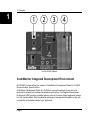
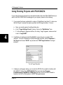
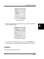
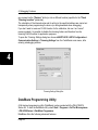
PK-HC08QY4
Starter Kit for
Freescale
MC68HC908QY4
User’s Manual
®
Copyright © 2004 SofTec Microsystems
DC00773
We want your feedback!
SofTec Microsystems is always on the look-out for new ways to improve its Products and
Services. For this reason feedback, comments, suggestions or criticisms, however small,
are always welcome.
SofTec Microsystems
E-mail (general information): [email protected]
E-mail (marketing department): [email protected]
E-mail (technical support): [email protected]
Web: http://www.softecmicro.com
Important
SofTec Microsystems reserves the right to make improvements to the PK Series of Starter Kits, their documentation and
software routines, without notice. Information in this manual is intended to be accurate and reliable. However, SofTec
Microsystems assumes no responsibility for its use; nor for any infringements of rights of third parties which may result
from its use.
SOFTEC MICROSYSTEMS WILL NOT BE LIABLE FOR DAMAGES RESULTING FROM LOSS OF DATA, PROFITS,
USE OF PRODUCTS, OR INCIDENTAL OR CONSEQUENTIAL DAMAGES, EVEN IF ADVISED OF THE POSSIBILITY
THEREOF.
Trademarks
Freescale™ and the Freescale logo are trademarks of Freescale Semiconductor, Inc.
Metrowerks and CodeWarrior are trademarks or registered trademarks of Metrowerks Corp.
Microsoft and Windows are trademarks or registered trademarks of Microsoft Corporation.
PC is a registered trademark of International Business Machines Corporation.
Other products and company names listed are trademarks or trade names of their respective companies.
Written by Paolo Xausa
PK-HC08QY4 User's Manual
Contents
1. Overview
What is the PK-HC08QY4 Starter Kit?
What is the MON08 Interface?
PK-HC08QY4 Board Layout
CodeWarrior Integrated Development Environment
Recommended Reading
Software Upgrades
2. Getting Started
PK-HC08QY4 Components
Host System Requirements
Installing the Software
Installing Metrowerks CodeWarrior IDE
Installing SofTec Microsystems Additional Components
Installing the Hardware
Application Tutorial
Additional Examples
3. Hardware Features
Introduction
MCU Section
USB to MON08 Interface
Demo Section
Prototype Area
4. Debugging Features
Creating Your Own Application
Using the Project Wizard to Create Your Application Skeleton
Starting your first Debugging Session
Using Existing Projects with PK-HC08QY4
Limitations
5
5
6
7
8
9
9
11
11
11
12
12
12
13
13
17
19
19
19
20
21
22
23
23
23
23
24
25
Contents
Notes and Tips
Entering Debug Session with CodeWarrior
Halt Debugging Handling
Breakpoints and Swi Instruction
Interrupt Execution during Steps
Reading Peripheral Status
Internal RC Oscillator Calibration
DataBlaze Programming Utility
5. Troubleshooting
Common Problems and Solutions
Communication Can’t Be Established with PK-HC08QY4
Stepping Execution is Slow
Communication Lost During Debugging
Getting Technical Support
Appendix A. Electrical and Physical Specifications
26
26
26
27
27
27
27
28
31
31
31
32
32
32
33
PK-HC08QY4 User's Manual
1
1. Overview
What is the PK-HC08QY4 Starter Kit?
The PK-HC08QY4 Starter Kit is an entry level tool which allows you to get started with the
Freescale MC68HC08 family of low-cost, high-performance microcontrollers units (MCUs).
The M68HC08 Family is a Complex Instruction Set Computer (CISC) with a Von Neumann
architecture. All MCUs in the family use the enhanced M68HC08 central processor unit
(CPU08) and are available with a variety of modules, memory sizes and types, and package
types.
The main features of the MC68HC908QY4 microcontroller are:
§
§
§
§
§
§
§
High-performance M68HC08 CPU core;
4096 bytes of FLASH memory;
128 bytes of RAM;
8 MHz internal bus operation at 5 V, 4 MHz at 3 V;
3.2 MHz internal oscillator;
4-channel, 8-bit analog-to-digital converter (ADC);
2-channel, 16-bit timer interface module (TIM).
The PK-HC08QY4 Starter Kit has been designed for the evaluation of the MC68HC908QY4
microcontroller and the debugging of small user applications.
The PK-HC08QY4 Starter Kit takes advantage of the Metrowerks’ CodeWarrior Integrated
Development Environment (which groups an Editor, Assembler, C Compiler and Debugger)
and the Freescale’s MON08 interface, which allows the download of the user application
into the microcontroller FLASH memory.
Together with CodeWarrior, PK-HC08QY4 provides you with everything you need to write,
compile, download, in-circuit emulate and debug user code. Full-speed program execution
allows you to perform hardware and software testing in real time. PK-HC08QY4 is
connected to the host PC through a USB port. A prototyping area allows you to wire your
own small application.
Page 5
1. Overview
1
PK-HC08QY4 offers you the following benefits:
§
§
§
§
§
§
Real-time code execution;
In-circuit debugging;
In-system programming and debugging through a MON08-compatible interface;
Demo area with push-buttons, potentiometer and user LEDs;
Prototyping area;
Metrowerks CodeWarrior IDE (the same user interface of all Freescale tools), with
editor, assembler, C compiler and debugger.
Note: the PK-HC08QY4 starter kit has been designed for evaluation purposes only. Even
though it has full-feature debugging options, its main limitations are:
§
The target microcontroller is fixed (soldered to the board).
§
The target microcontroller runs only at 5 V.
§
The data transfer rate (PC to target and target to PC) is slow. This results in high
programming times.
For serious debugging, we suggest you to switch to the SofTec Microsystems inDARTHC08 Series of debugging/programming tools.
What is the MON08 Interface?
The HC08’s integrated MON08 interface allows you to update the content of FLASH
program memory when the chip is already plugged on the application board. The MON08
interface can be implemented with a minimum number of added components and board
area impact.
PK-HC08QY4 features a USB-to-MON08 circuitry which allows the host PC to communicate
to the microcontroller through a standard USB cable.
Page 6
PK-HC08QY4 User's Manual
1
PK-HC08QY4 Board Layout
The PK-HC08QY4 board has the following hardware features:
1. A “USB to MON08 Interface” section. It contains the circuitry needed to electrically
and logically translate MON08-like commands sent by the host PC through the USB
cable to the MON08 interface of the microcontroller. The PK-HC08QY4 board is
powered by the USB bus.
2. A “Demo” section. It features a RESET push-button, one user push-button, a
potentiometer and eight user LEDs.
3. A “MCU” section. It contains a soldered, 16-pin MC68HC908QY4 device (in SOIC
package) with connectors to access the I/O pins of the microcontroller for expansion
prototyping. A 28 MHz clock signal is provided (used to generate an internal bus
frequency of 7 MHz).
4. A “Prototype” section. You can wire your own circuit here. The prototype section
features both a standard, thru-hole area (for mounting traditional components) and a
SMD area (for soldering SMD components in SOIC package).
Page 7
1. Overview
1
The PK-HC08QY4 Board
CodeWarrior Integrated Development Environment
PK-HC08QY4 comes with a free version of CodeWarrior Development Studio for HC(S)08
Microcontrollers, Special Edition.
CodeWarrior Development Studio for HC(S)08 is a powerful and easy-to-use tool suite
designed to increase your software development productivity. Its Integrated Development
Environment (IDE) provides unrivaled features such as Processor Expert application design
tool, full chip simulation, Data Visualization and project manager with templates to help you
concentrate on the added value of your application.
Page 8
PK-HC08QY4 User's Manual
The comprehensive, highly visual CodeWarrior Development Studio for Freescale HC(S)08
Microcontrollers enables you to build and deploy HC(S)08 systems quickly and easily. This
tool suite provides the capabilities required by every engineer in the development cycle,
from board bring-up to firmware development to final application development.
To use the Special Edition (4 KB code-size limited), you must have a valid license key.
Without the license key the product will run in a 1 KB code-size limited demonstration mode.
To request the license key, please refer to Metrowerks website.
This documentation covers the basic setup and operation of the CodeWarrior IDE, but does
not cover all of its functions. For further information, please refer to the CodeWarrior on-line
help and on-line documentation provided.
Recommended Reading
This documentation describes how to use PK-HC08QY4 together with Metrowerks
CodeWarrior HC(S)08 IDE. Additional information can be found in the following documents:
§
§
§
§
PK-HC08QY4 Schematic.
Metrowerks’ Additional Documentation—Available from the CodeWarrior IDE.
CPU08 Central Processor Unit Reference Manual—Programming reference
containing the description of the full HC08 instruction set.
MC68HC908QT/QY Data Sheets.
Software Upgrades
The latest version of the PK-HC08QY4 system software is always available free of charge
from our website: http://www.softecmicro.com. Metrowerks CodeWarrior upgrades can be
found at http://www.metrowerks.com.
Page 9
1
PK-HC08QY4 User's Manual
2. Getting Started
2
PK-HC08QY4 Components
The PK-HC08QY4 package includes the following items:
1.
2.
3.
4.
5.
6.
The PK-HC08QY4 evaluation board;
A USB cable;
The Metrowerks CodeWarrior HC(S)08 CD-ROM;
The SofTec Microsystems PK-HC08QY4 “System Software” CD-ROM;
A “QuickStart Tutorial” color poster;
This user’s manual.
Host System Requirements
The PK-HC08QY4 in-circuit debugger is controlled by an Integrated Development
Environment running under Windows (CodeWarrior HC(S)08). The following hardware and
software are required to run the CodeWarrior HC(S)08 user interface together with PKHC08QY4:
1. A 133-MHz (or higher) PC compatible system running Windows 98, Windows 2000 or
Windows XP;
2. 128 MB of available system RAM plus 500 MB of available hard disk space;
3. A USB port;
4. CD-ROM drive for installation.
Page 11
2. Getting Started
Installing the Software
2
Note: before to connect the PK-HC08QY4 board to the PC, it is recommended that you
install all of the required software first (see below), so that the PK-HC08QY4 USB driver will
be automatically found by Windows when you connect the board.
PK-HC08QY4 requires that both Metrowerks CodeWarrior IDE and SofTec Microsystems
PK-HC08QY4 additional components be installed in the host PC.
Note: Metrowerks CodeWarrior HC(S)08 IDE must be installed first. Please note that PKHC08QY4 only works with CodeWarrior for HC(S)08 version 3.0 or above.
Installing Metrowerks CodeWarrior IDE
To install the CodeWarrior IDE insert the CodeWarrior CD-ROM into your computer’s CDROM drive. A startup window will automatically appear. Follow the on-screen instructions.
Installing SofTec Microsystems Additional Components
The SofTec Microsystems additional components install all of the other required
components to your hard drive. These components include:
§
§
§
§
The PK-HC08QY4 USB driver;
PK-HC08QY4 software plug-in for CodeWarrior HC(S)08;
Examples;
Documentation in PDF format.
To install the SofTec Microsystems additional components insert the SofTec Microsystems
“System Software” CD-ROM into your computer’s CD-ROM drive. A startup window will
automatically appear. Choose “Install Instrument Software” from the main menu. A list of
Page 12
PK-HC08QY4 User's Manual
available software will appear. Click on the “PK-HC08 Series Additional Components”
option. Follow the on-screen instructions.
Note: if you are installing the PK-HC08QY4 additional components on Windows 2000 or
Windows XP you must have logged in as Administrator.
Installing the Hardware
The PK-HC08QY4 board is connected through a USB port to a host PC. Connection steps
are listed below in the recommended flow order:
1. Install all the required system software as described in the previous section.
2. Insert one end of the USB cable into a free USB port.
3. Insert the other end of the USB cable into the “USB” connector on the PK-HC08QY4
board. The green “POWER” LED on the instrument should turn on. Windows will
automatically recognize the instrument and will load the appropriate USB driver.
Note: both Windows 2000 and Windows XP may issue a warning the first time PKHC08QY4 is connected to the PC. This warning is related to the fact that the USB driver
used by PK-HC08QY4 is not digitally signed by Microsoft, and Windows considers it to be
potentially malfunctioning or dangerous for the system. However, you can safely ignore the
warning, since every kind of compatibility/security test has been carried out by SofTec
Microsystems.
Application Tutorial
This section will provide a step-by-step guide on how to launch your first PK-HC08QY4
project and get started with the CodeWarrior HC(S)08 user interface.
Page 13
2
2. Getting Started
The sample application reads the position of the potentiometer (connected to the
microcontroller’s ADC peripheral) and displays this value on the LEDs.
To execute the sample application, follow the next steps:
2
1. Ensure that the PK-HC08QY4 board is connected to the PC (via the USB cable).
2. Verify that both the J5 and J4 jumpers (near the potentiometer and the LEDs) are
inserted. This is the factory configuration, and indicates that both the potentiometer and
the LEDs are connected to the lines of the microcontroller.
3. Start the CodeWarrior HC(S)08 IDE by selecting Start > Programs > Metrowerks
CodeWarrior > CW08 > CodeWarrior IDE. The CodeWarrior HC(S)08 IDE will open.
4. From the main menu, choose File > Open. Select the “adc.mcp” workspace file that is
located under the “\Program Files\Metrowerks\CodeWarrior
CW08\(CodeWarrior_Examples)\HC08\SofTec Microsystems\PK-HC08QY4\C\Adc”
directory. Click “Open”. The following window will appear.
The Project Window
5. The C code of this example is contained in the “main.c” file. Double click on it to open.
The following window will appear.
Page 14
PK-HC08QY4 User's Manual
2
The Example’s Source Code
6. From the main menu, choose Project > Debug. This will compile the source code,
generate an executable file and download it to the PK-HC08QY4 board.
7. A new debugger environment will open.
Page 15
2. Getting Started
2
Debugging Session Started
8. From the main menu, choose Run > Start/Continue. The program will be executed in
real-time. By rotating the potentiometer on the PK-HC08QY4 board, you affect the
results of the A/D conversion, and the value of each conversion is displayed on the
LEDs.
9. From the main menu, choose Run > Halt. The program execution will stop. The next
instruction to be executed is highlighted in the Source window.
10. From the main menu, choose Run > Single Step. The instruction highlighted in the
Source window will be executed, and the program execution will be stopped
immediately after.
Page 16
PK-HC08QY4 User's Manual
11. In the Source window, insert a breakpoint at the “PTB = ADR;” instruction in the main
function. To insert the breakpoint, right-click on the “PTB = ADR;” line and, from the
pop-up menu, select “Set Breakpoint”.
12. Rotate the potentiometer slightly. Then, from the main menu, choose Run >
Start/Continue. The application will restart from where it was previously stopped. The
application will stop at the breakpoint location as soon as the next A/D conversion is
done.
13. Issue a Single Step command (Run > Single Step). The new value of the A/D
conversion will be displayed on the LEDs.
Congratulations! You have successfully completed this tutorial! You can continue to
experiment with the CodeWarrior user interface and discover by yourself its potentialities.
For an in-depth guide of all of the user interface features, select Help > CodeWarrior Help
from the CodeWarrior HC(S)08 IDE’s main menu.
Additional Examples
Additional examples can be found under the “\Program Files\Metrowerks\CodeWarrior
CW08\(CodeWarrior_Examples)\HC08\SofTec Microsystems\PK-HC08QY4” directory.
Page 17
2
PK-HC08QY4 User's Manual
3. Hardware Features
Introduction
PK-HC08QY4 is an in-circuit debugger—it programs files into the MC68HC908QY4
microcontroller and offers debugging features like real-time code execution, stepping, and
breakpoints. Its debugging features are achieved thanks to the microcontroller’s integrated
MON08 monitor module.
Contrariwise to traditional in-circuit emulation (where the target application is executed and
emulated inside the emulator), PK-HC08QY4 uses the very same target microcontroller to
carry on in-circuit execution. This means that all microcontroller’s peripherals (timers, A/D
converters, I/O pins, etc.) are not reconstructed or simulated by an external device, but are
the very same target microcontroller’s peripherals. Moreover, the PK-HC08QY4 debugging
approach ensures that the target microcontroller’s electrical characteristics (pull-ups, lowvoltage operations, I/O thresholds, etc.) are 100% guaranteed.
MCU Section
The “MCU” section contains the target microcontroller and the additional circuitry needed for
the correct microcontroller startup. In detail:
§
§
§
§
An MC68HC908QY4 microcontroller, together with all necessary filter capacitors.
A jumper to select either an on-board generated 28 MHz oscillator frequency or an user
provided clock signal (to be provided to the PTA5/OSC1 pin).
A push-button in the “Demo” section is directly connected to the microcontroller’s reset
pin (PTA3/RST).
All of the microcontroller’s pins are available on the two connectors placed near the
microcontroller.
Page 19
3
3. Hardware Features
USB to MON08 Interface
3
This section contains the circuitry needed to electrically and logically translate MON08-like
commands sent by the host PC through the USB cable to the MON08 interface of the
microcontroller.
The USB interface is based on a Freescale MC68HC908JB16 microcontroller, which
features an on-board, low-speed USB peripheral.
The USB bus provides the power supply for the board. To protect the USB bus against short
circuits that may occur during experiments, the power supply circuitry features a 200 mA
auto-restore fuse.
Note: even though USB specifications require low-speed devices to be used only with a
captive or manufacturer-specific USB cable, we have decided to use a standard USB cable.
We therefore recommend that you use the PK-HC08QY4 board with the USB cable
provided or, if you use another USB cable, ensure that the cable length does not exceed 2
meters.
Page 20
PK-HC08QY4 User's Manual
Technical Note. The MC68HC908QY device (like all devices of the HC08 family) features a
monitor code which, through a serial communication line, allows the programming and the
in-circuit debugging of the user application.
The monitor code is executed in “monitor mode”; the user application is executed is “user
mode”. To enter the monitor mode some microcontroller lines must be properly driven (for
further details please refer to the microcontroller’s data sheet).
The PK-HC08QY4 “USB to MON08 Interface” section groups the circuitry needed to
generate the required signals to enter the monitor mode and to communicate with the host
PC’s USB port. In particular, to enter the monitor mode, the “USB to MON08 Interface”
circuitry generates/handles the following signals:
§
§
§
§
§
§
An high-level voltage signal (VTST = 8.2 V) on the PTA2/IRQ pin of the microcontroller;
A reset signal on the PTA3/RST pin of the microcontroller;
The PTA1 and PTA4 pins of the microcontroller are driven to the following levels:
PTA1 = 1, PTA4 = 0;
A power supply line to drive the VDD pin of the microcontroller to 0 V or 5 V;
A single-wire, bidirectional serial communication line on the PTA0 pin of the
microcontroller;
A 28 MHz clock signal on the PTA5/OSC1 pin of the microcontroller (in order to
communicate at a speed of about 27,000 baud over the serial communication line
specified above).
All of the above signals are generated by the MC68HC908JB16 microcontroller through a
USB interface.
Demo Section
The “Demo” section groups push-buttons, a potentiometer, and user LEDs. In detail:
§
Eight user LEDs, together with jumpers to connect them to/disconnect them from the
microcontroller’s Port B pins. All of the microcontroller I/O pins provide the required
current to drive the low-current LEDs used by the starter kit, so no external transistors
are needed.
Page 21
3
3. Hardware Features
§
§
§
3
One user push-button, connected to the microcontroller’s PTA4 pin. In order to read the
status of this push-button, the microcontroller’s internal pull-up must be enabled
(through software) on this pin.
One push-button connected to the microcontroller’s rest pin (PTA3/RST).
A potentiometer, together with a jumper to connect it to/disconnect it from the
microcontroller’s PTA1 pin.
Prototype Area
The prototype section features both a standard, thru-hole area (for mounting traditional
components) and a SMD area (for soldering SMD components in SOIC package).
Page 22
PK-HC08QY4 User's Manual
4. Debugging Features
Creating Your Own Application
Using the Project Wizard to Create Your Application Skeleton
CodeWarrior HC(S)08 helps you get started with your own application by including a project
wizard specific for HC08-based SofTec Microsystems boards. To create a new PKHC08QY4 project:
1. From the main menu, select File > New.
2. A dialog box will appear. Select “HC(S)08 New Project Wizard”.
3. Follow the Project Wizard steps, making sure you select the correct microcontroller
derivative you are working with and that the “SofTec Microsystems” target connection
is used.
Starting your first Debugging Session
The first time you enter a debugging session (by selecting Project > Debug from the
CodeWarrior’s main menu) the MCU Configuration dialog box will open, asking you to select
the debugging hardware connected to the PC. Make sure that the hardware code is set to
“PK-HC08QY4”.
The MCU Configuration Dialog Box
Page 23
4
4. Debugging Features
Using Existing Projects with PK-HC08QY4
If your project has been targeted to an emulator/simulator other than PK-HC08QY4 and you
wish to use PK-HC08QY4 as the debugger for your project, please do the following:
1. If your project has been created with a version of CodeWarrior less than 3.0, make sure
that the “target” command line option specifies the GDI target interface. To do so:
a. Open your existing project’s settings dialog box.
b. In the “Target Settings Panels” section, click on the “Build Extras” item.
c. If, in the debugger’s argument edit box, the string “-target” appears, make sure that
is set to “-target=GDI”.
4
2. CodeWarrior is interfaced to the PK-HC08QY4 engine through a so-called “GDI
interface”. From the CodeWarrior HC(S)08 debugger interface, select Component >
Set Target and choose “HC08” as processor and “GDI Target Interface” as target
interface.
The Set Target Dialog Box
3. A dialog box will appear asking you to locate the GDI DLL file needed to interface with
PK-HC08QY4. Select the inDART-HC08.dll file located into the \Program
Files\Metrowerks\CodeWarrior CW08\prog\ directory (the PK-HC08QY4 board is
based on the SofTec Microsystems’ inDART debugging engine).
Page 24
PK-HC08QY4 User's Manual
The GDI Setup Dialog Box
4. The MCU Configuration dialog box will appear allowing you to select the PK-HC08QY4
board as the hardware debugger.
The MCU Configuration Dialog Box
5. On the CodeWarrior HC(S)08 debugger interface a new menu (inDART-HC08) will be
created. From this menu, select Load and locate the object file your project is based on.
Limitations
Some hardware and software limitations apply.
Page 25
4
4. Debugging Features
§
§
§
§
§
§
4
§
The PTA0, PTA2, PTA3 and PTA5 pins of the microcontroller are reserved—in
particular, the PTA0 bit in the DDRA Register must not be changed (must be left to
input);
The MON08 lines (PTA1 and PTA4) and the PTA3/RESET line have a 1 KOhm serial
resistor;
Since the IRQ/PTA2 line is reserved (and it is driven to V TST) the “bil” and “bih”
Assembly instructions will result in no branch and always branch, respectively.
The COP must be disabled at the beginning of the user code.
The Break Module peripheral is reserved, and only one hardware breakpoint is
available—however, you can insert a “swi” instruction into your code to generate a
software breakpoint;
The “Halt” debugging command (in the CodeWarrior IDE) will not work unless the IRQ
interrupt is properly handled;
13 bytes of stack are wasted by the on-chip monitor—therefore the addresses from SP13 to SP are reserved.
Notes and Tips
Entering Debug Session with CodeWarrior
When entering a debug session, the target microcontroller’s FLASH memory is
automatically erased, programmed with the user application, and the trimming value (if the
trimming option is enabled) is automatically calculated and programmed.
Halt Debugging Handling
The “Halt” debugging command (in the CodeWarrior IDE) will not work unless the IRQ
interrupt is properly handled. In particular, the following precautions must be taken in the
application’s source code.
1. Global interrupts must be enabled (use the “cli” instruction);
2. The IRQEN bit in the CONFIG2 register must be set to 1;
3. The IRQ interrupt vector must be handled;
Page 26
PK-HC08QY4 User's Manual
4. The IRQ handling routine must include the following code:
bil *
swi
rti
; Waits for the IRQ signal to go high
; Jumps to monitor code
; Returns from interrupt
Breakpoints and Swi Instruction
The HC08’s on-chip debug module only handles one hardware breakpoint. However, you
can force the program execution to stop at other specific locations by inserting the “swi”
Assembly instruction on your source code.
Interrupt Execution during Steps
When issuing stepping instructions and there are pending interrupts, the debugger will not
step inside the interrupt handling routine, but the whole interrupt handling routine is
executed. An exception is when you single step on an Assembly instruction which branches
to itself: in this case, interrupts which may occur are not handled.
Reading Peripheral Status
Care must be taken when reading some peripheral’s status/data registers, since a reading
operations may cause the clearing of flags. This may happen when the Memory window or
the Data window is open, since these windows read microcontroller’s resources during
refresh operations.
Internal RC Oscillator Calibration
The MC68HC908QY microcontroller features an internal, trimmerable RC oscillator working
at 3.2 MHz. The MC68HC908QY microcontroller is factory pre-programmed with a default
trimming value in a dedicated FLASH location (specified in the datasheet). However, due to
the different real-world conditions of the user’s system, it is always suggested to recalibrate
the internal oscillator to reflect the actual working conditions.
The Trimming Settings dialog box allows you to enable/disable the trimming feature. If
enabled, it is possible to specify whether to save the calculated trimmed value in the default
location (the location suggested either by Freescale or SofTec Microsystems, restorable at
Page 27
4
4. Debugging Features
any moment via the “Restore” button) or into a different location (specified in the “Flash
Trimming Location” parameter).
The calculation of the trimmed value and its writing to the specified address are carried out
transparently when programming the device (or during download when debugging).
If you don’t want to reserve a FLASH location for the calibration, but use it as “normal”
memory instead, it is possible to disable the trimming feature and therefore free the
trimming FLASH location for application purposes.
To open the Trimming Settings dialog box choose inDART-HC08 > MCU Configuration >
Communication Settings > Trimming Settings from the CodeWarrior main menu, after
entering a debugging session.
4
Trimming Settings Dialog Box
DataBlaze Programming Utility
A full-featured programming utility (DataBlaze) is also provided with the PK-HC08QY4
Starter Kit. To start the DataBlaze utility select Start > Programs > SofTec Microsystems
> PK-HC08 Series > DataBlaze Programmer.
DataBlaze offers the following advanced features:
Page 28
PK-HC08QY4 User's Manual
§
§
§
§
§
§
Memory editing;
Blank check/erase/program/verify/read operations;
Project handling;
One-button, multiple-operations programming (“Auto” feature);
Automatic trimming calibration;
Serial numbering.
Note: due to the evaluation purposes of the PK-HC08QY4 starter kit (and therefore to the
slow data transfer rate from the PC to the target and vice versa), the DataBlaze
programming utility takes a long time to write to/read from the whole microcontroller
memory. For serious debugging/programming, we suggest you to switch to the SofTec
Microsystems inDART-HC08 Series of debugging/programming tools.
Page 29
4
4. Debugging Features
4
The DataBlaze User Interface
Page 30
PK-HC08QY4 User's Manual
5. Troubleshooting
Common Problems and Solutions
This section reports some common problems that may arise during general use.
Communication Can’t Be Established with PK-HC08QY4
1. Make sure the PK-HC08QY4 starter kit is connected to the PC and powered on. PKHC08QY4 is powered by the USB connection.
2. If you connected the PK-HC08QY4 board to the PC before installing the CodeWarrior
user interface and the SofTec Microsystems Additional Components, the PK-HC08QY4
USB driver may not have been correctly installed on your system. Unplugging and
replugging the USB cable is of no use, since Windows has marked the device as
“disabled”. As a consequence, CodeWarrior cannot communicate with the PKHC08QY4 board.
To restore the USB driver (provided both CodeWarrior and SofTec Microsystems
Additional components have been installed), perform the following steps under
Windows XP:
§
§
§
§
§
§
§
Plug the PK-HC08QY4 board to the PC.
Open the Control Panel (Start > Settings > Control Panel).
Open the “System” options.
Select the “Hardware” tab.
Click the “Device Manager” button.
The “PK-HC08 Series Starter Kit” device will be shown with an exclamation mark
next to it. Double click on this device.
In the “General” tab, click the “Reinstall Driver” button. Follow the on-screen
instructions.
Page 31
5
5. Troubleshooting
3. Make sure you are working with the correct hardware model. To view/change the
hardware model in use, choose inDART-HC08 > MCU Configuration from the
CodeWarrior HC(S)08 debugger’s main menu.
4. If the inDART-HC08 menu is not present in the CodeWarrior HC(S)08 debugger’s main
menu, this is because the target has not been recognized by CodeWarrior (“No link to
Target” appears in the status bar). In this case, from the GDI menu, choose MCU
Configuration and verify that the hardware code is set correctly.
Stepping Execution is Slow
When the Memory window is open, step commands may execute slower, since the Memory
window contents need to be refreshed after every step.
Communication Lost During Debugging
§
§
5
Make sure that the target microcontroller’s I/O bit corresponding to the PTA0 line (the
MON08 line dedicated to the bidirectional communication) is set to input by your
program.
Make sure that your program works correctly. Among other things, your program must
not access reserved memory locations.
Getting Technical Support
Technical assistance is provided free to all customers. For technical assistance,
documentation and information about products and services, please refer to your local
SofTec Microsystems partner.
SofTec Microsystems offers its customers a free technical support service at
[email protected]. Before getting in contact with us, we advise you to check that
you are working with the latest version of the PK-HC08QY4 system software (upgrades are
available free of charge at http://www.softecmicro.com). Additional resources can be found
on our HC08 online discussion forum.
Page 32
PK-HC08QY4 User's Manual
Appendix A. Electrical and Physical
Specifications
Operating Voltage
4.75 to 5.0 V DC (provided by the USB connection)
Power Consumption
200 mA (max)
Dimensions
137 x 86 x 15 mm
Weight
55 g
Operating Temperature
0 °C to 50 °C
Storage Temperature
-20 °C to 70 °C
Humidity
90% (without condensation)
Electrical and Physical Specifications
A
Page 33
Mouser Electronics
Authorized Distributor
Click to View Pricing, Inventory, Delivery & Lifecycle Information:
Freescale Semiconductor:
PK-HC08QY4 PK-HCS08GB60


![[DRAFT] DEMO908JL16 User`s Manual](http://vs1.manualzilla.com/store/data/005639706_1-2a84cd2ce2f0b318fdb7aae7896f2a79-150x150.png)