1
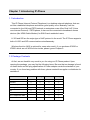
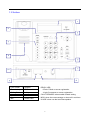
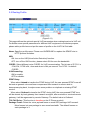
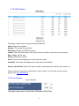
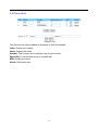
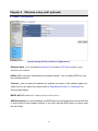
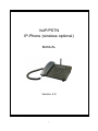
VoIP/PSTN IP-Phone (wireless optional) MANUAL Version: 4.0 2008/09/25 1 Table of contents Chapter 1 Introducing IP-Phone ..................................................................................................... 4 1.1 Introduction ....................................................................................................................... 4 1.2 Package Contests ............................................................................................................. 4 1.3 Surface.............................................................................................................................. 5 1.4 Key Features..................................................................................................................... 6 1.5 Specifications .................................................................................................................... 7 Chapter 2 Basic Application Concept.............................................................................................. 8 2.1 Phone to Phone Direct Dial via PSTN network ................................................................. 8 2.1 Phone to Phone Direct Dial via Internet ............................................................................ 8 2.3 Phone through Gatekeeper/Proxy Server to Dial .............................................................. 9 Chapter 3 Configuration................................................................................................................ 10 3.1 Connection .......................................................................................................................11 3.2 System status.................................................................................................................. 18 3.3 Register Server ............................................................................................................... 19 3.4 VoIP Call Out................................................................................................................... 24 3.5 Routing Profile................................................................................................................. 27 3.6 Forwarding ...................................................................................................................... 29 3.7 Line Configure................................................................................................................. 30 3.8 Phone Book..................................................................................................................... 32 3.9 Auto Provision Server...................................................................................................... 33 Chapter 4 Advance Setup ............................................................................................................. 35 4.1 NAT Traversal.................................................................................................................. 35 4.2 Listen Port ....................................................................................................................... 36 4.3 VoIP Package.................................................................................................................. 37 4.4 RTP Packet Summary..................................................................................................... 39 4.5 Gain................................................................................................................................. 40 4.6 QOS ................................................................................................................................ 41 4.7 CDR ................................................................................................................................ 42 2 Chapter 5 Setting with LCD Menus ............................................................................................ 43 5.1 Front Panel configure with LCD ...................................................................................... 43 5.2 LED Display .................................................................................................................... 45 Chapter 6 Wireless setup (wifi optional) ..................................................................................... 46 6.1 Basic Configuration ......................................................................................................... 46 6.2 WEP .............................................................................................................................. 47 6.3 Advanced ........................................................................................................................ 48 6.4 MAC Filter ....................................................................................................................... 50 6.5 Station List....................................................................................................................... 51 6.6 Security ........................................................................................................................... 51 6.7 RADIUS........................................................................................................................... 55 Chapter 7 Configure IP phone as a Wireless Station / Client ………………………………………56 7.1 Wireless Station (Access Point) ...................................................................................... 56 7.2 Wireless Client (AP Client) ............................................................................................ 57 3 Chapter 1 Introducing IP-Phone 1.1 Introduction This IP Phone (Internet Protocol Telephone) is a desktop network telephone that can act like a traditional telephone and deliver good quality voice. Basically, it will be connected to the LAN and PSTN network or enterprise as an office Dual VoIP (Voice over Internet Protocol) / PSTN phone; it also can be connected to broadband access devices (like XDSL/Cable Modem) for SOHO and residential users. H.323 and SIP are the major type of VoIP protocol in the world. The IP Phone supports both of H.323 and SIP communications simultaneously. Wireless function (Wifi) is optional for users who need it, if you purchase IP2020 or IP2021 which are not Wifi function inside, please ignore Chapter 6. 1.2 Package Contents At first, we are thankful very much to you for using our IP Phone product. Upon opening the package, you may find the following items. Be sure that no damage is found on these items and the plug specification of Power adaptor meets the standard of your country. If you found any problem with them, please contact the supplier or distributor for assistance. contents IP2020 IP2020g IP2021 IP2021g The main unit ◎ ◎ ◎ ◎ Handset ◎ ◎ ◎ ◎ Power adapter ◎ ◎ ◎ ◎ Quick guide ◎ ◎ ◎ ◎ CD ◎ ◎ ◎ ◎ RJ-45 Ethernet cable ◎ ◎ ◎ ◎ ◎ ◎ RJ-11 Telephone cable Antenna ◎ ◎ 4 1.3 Surface 1 2 3 4 6 5 7 10 9 1. LCD Screen 8 6. Speaker READY LED: 2. Function keys 7. PSTN Jack >Flash: Failed on server registration 3. Dialing Pad 8. LAN port >Light: Successes on server registration 4. Speed Dial 9. WAN Port 5. MIC 10 Power Jack CALL FORWARD: when enable forward setting MSG: when the new message or miss call in real time IN USE: when use the hand-free speaker 5 1.4 Key Features VoIP 1. VoIP / PSTN support 2. SIP/H.323 protocol simultaneously 3. VPN (PPTP , L2TP and Ipsec) pass through 4. VPN Client support (PPTP & L2TP) 5. Support UPnP / Port Mapping 6. Support SNTP 7. Support Static-IP / PPPoE / DHCP / Bridge mode 8. Support Multiple VoIP Server (SIP&H.323) Domain (up to 4) 9. Support STUN server / Outbound Proxy 10. Customizable Ring melody for VoIP/PSTN/On-Hold 11. Message for Value-add 12. Support forward (Always/Busy/No-Answer) in VoIP 13. Support Call Rejection function key 14. Support Call Hold/Mute function key 15. LCD support Call timer display 16. Support IP Direct Call 17. Support Auto Provision Server 18. Management by WEB GUI and Keypad 19. Support IP TOS (Type of Service) for VoIP 20. Support Bandwidth Control Wireless ( Wifi optional) 1. Compliant with IEEE 802.11g (n) standard. 2. Up to 54M bps data transfer rate ( IP2020g, IP2021g) 3. Up to 108M bps data transfer rate (IP2020n, IP2021n) 4. MAC address filter function. 5. WEP Support: Support 64/128 bit WEP (Wired Equivalent Privacy) encryption. 6. WPA Support: Support WPA-PSK Pass Phrase, WPA G-Rekey and WPA. TKIP/AES Data Encryption. 6. WPA2 Support: Support WPA2-PSK Pass Phrase and WPA2. 7. Support RADIUS server authentication. 6 1.5 Specifications z z z z z z z z z z z z z z z z z 1x RJ-11 PSTN port 1 x RJ-45 10/100Mbps WAN Ethernet Port (Auto MDI-II/MDI-X) 3 x RJ-45 10/100Mbps LAN Ethernet Ports (Auto MDI-II/MDI-X) Display: 20(characters)*2(lines) Physical: 150 X 170 X 43 mm Power: AC100V-240V, DC 9V/1.3A (Max) Dimension: 215 x 160 x 55 mm (W/D/H) Weight: 1.3 kg (full set) LED Indicators : Ready, Call Forward, MSG, INUSE 33 feature keys Supported Protocol: UDP, TCP, Standard H.323 & SIP v2.0 Audio CODEC: -G.711 A-law / u-law, (64kbps) -G.723.1, (5.3 or 6.3kbps) -G.729/G.729a, (8kbps) DTMF / Call progress tone detection and generation G.168 echo cancellation User friendly Web configure interface Configuration/Upgrade by Web or Provision Server Build-in watching dog for auto recovery 7 Chapter 2 Basic Application Concept The IP Phone supports 3 ways of calling method as described below (Figure2-1) 2.1 Phone to Phone Direct Dial via PSTN network The IP Phone support PSTN connectivity, you can easily to place or receive PSTN calls. Example: press “*” to switch PSTN mode, then start to make a PSTN call (Please refer to Fig 2.1 for this call way ①) 2.1 Phone to Phone Direct Dial via Internet This is Peer-to-Peer dialing method. You can please a VoIP call to a remote IP Phone with dialing its IP address directly via keypad. But, be sure that the calling and the called remote IP Phones must have fixed real IP address. Example: press keypad (MENUÆViewÆCall by URL) to enter “Call by URL” mode, and then enter the IP dial number information step by step. (Please refer to Fig 2.1 for this call way ②) 8 2.3 Phone through Gatekeeper/Proxy Server to Dial This is the most common dialing method. You can place a VoIP call to any IP Phone(s) or gateways. In this case, the IP Phone doesn’t need a fixed real IP address. Please call your service provider to get more information. Example: press 0708825252 to another voip phone or gateways via the same server (Please refer to Fig 2.1 for this call way ③) 9 Chapter 3 Configuration The default setting of DHCP Server inside IP-Phone is turn ON, So please set up your PC’s TCP/IP network as “Get IP Automatically” from DHCP to get internal IP from gateway. By default, the IP-Phone will become the network gateway and default IP is 192.168.22.1 and will assign your PC IP as 192.168.22.x. Please go to “Control Panel” → ”Network”. In the “Configure” page, choose the TCP/IP of LAN card, and press “Properties” please choose “Obtain IP Address Automatically” Launch your browser and open the IP-Phone WEB-UI page as http://192.168.22.1 (Figure3-1) The default User name is voip The default Password is 1234 10 3.1 Connection Click “Connected Type” option below “System Setup\Wan” item: Please select the type of Internet connection you have and set up the router to use the Dynamic IP Address, Static IP Address, PPPoE, PPTP or L2TP connection. If your ISP has not given you an IP address, select Dynamic IP Address (default). If you have been given a specific IP address, select Specify an IP Address. Wireless control item only shows on models which embedded wireless (WIFI) function. (Figure3-2) (Figure3-3) 11 Connection Type There are six ways to connect to the Internet. They are Dynamic IP, Static IP, PPPoE, PPTP and L2TP. The cable modem ISP usually requests you to obtain the WAN IP dynamically. Some ISPs request you to fill the host name. To do this, please go to “System/System Settings” page to change the host name. A. Dynamic IP Address Request IP address You can specify the IP address you desired. neglect it and provides you a different one. But the ISP has the right to MTU (576-1500) You can specify the MTU (maximum transmission unit) of your home gateway. The default value is 1500 bytes and in normal case, you don’t have to change. MAC Cloning Some ISPs will identify the MAC address registered by the user. If not registered, the ISP won’t allow the traffic to pass. Enable the MAC cloning function will change WAN MAC to the registered one. MAC Address The MAC address will be cloned. Clone MAC Address 12 This button is use to detect the PC, which is browsing this page, and make its MAC address to be the MAC address to clone. B. Static IP Address IP address assigned by your ISP Set the IP address that assigned by the ISP. Subnet Mask Set the subnet mask of the network. ISP Gateway Address Set the ISP’s gateway IP address. This address routes packets to Internet. C. PPPoE 13 This page is the PPPoE configuration page. Most of the ISPs request the user to connect to central office (CO) side via PPPoE, acronym of Point-to-Point Protocol over Ethernet, which provides authentication, authorization and accounting. User Name Enter the user name provided by your ISP to identify the computer using PPPoE. Password Enter the password provided by your ISP to identify the computer using PPPoE. Please retype your password Retype the password to make sure type correct password. Service Name Some ISP provides the service name of this PPPoE connection. enter this item, or make it blank. If so, MTU (546-1492) Maximum Transmission Unit (MTU) is the largest physical packet size measured in bytes, which a network can transmit. Any messages larger 14 than the MTU are divided into smaller packets before sent. In ordinary, that the user does not have to worry about the MTU size, the gateway routing engine will handle the MTU differences between PPP and the LAN Ethernet side. But for some old PPPoE server, you have to make the MTU size of the PPPoE side smaller than the default value, or some Web side is not able to access. PPPoE MTU should be set between 546 and 1492. Maximum Idle Time (60-3600) Set a period of time to disconnect PPPoE connection, when user’s idle time greater than it. The Maximum Idle Time is only worked on the auto-connect mode. It makes no effect on manual-on mode and keep-alive mode (see Connection Mode). Connection Mode Three connection modes are designed to fit different request. keep-alive, manual-on, and auto-connect mode. They are For the manual-on mode, you have to dial-on and cut out the connection manually. The keep-alive mode will make the connection always on. If the line is dropped, the modules will try to connect to the PPPoE server always. The auto-connect mode is designed to save the communication cost for the user. In the beginning of powered on, the link will not be built. Instead, the gateway monitors the traffic from LAN side to the Internet. The sooner routing traffic was issued, the later PPPoE link is established. The gateway continually watches the LAN to WAN traffic, if there is no activity for more than the Maximum Idle Time, the connection will be dropped. D. Bridge 15 User can set this device work as a bridge, set the necessary information. A network bridge connects multiple network segments at the data link layer (layer 2) of the OSI model, and the term layer 2 switch is often used interchangeably with bridge. Bridging group IP address Enter the bridging IP address in this column. Bridging group Subnet Mask Enter the bridging Subnet Mask in this column. Bridging group Gateway Address Enter the bridging gateway IP address in this column. E. DNS This page sets the primary and secondary DNS servers, which were given by your ISP or known to you. When a domain name request received, the 16 gateway tries to resolve to it from the Primary Domain Name Server. Resolving failed, the gateway tries the Secondary sever again. Static DNS Server Check this item to make the primary and secondary DNS server at the next two rows active. If this field is not enabled, the statically configured DNS server will not take effect. Domain Name Server (DNS) Address Set your primary DNS in this field. Secondary DNS Address (optional) Set your secondary DNS to use when the primary DNS does not work. 17 3.2 System status System Status You can use the Status screen to see the connection status of WAN/LAN interfaces, firmware and hardware version numbers, and the number of connected clients to your network. The following items are included in this screen: INTERNET - Displays WAN connection type and status. GATEWAY - Displays system IP settings, as well as DHCP, NAT and Firewall status. INFORMATION - Displays the number of connected clients, as well as the Router's hardware and firmware version numbers. Please click to System SetupÆSystemÆSystem Status to see the follow information (Figure3-8) 18 3.3 Register Server If this VoIP Router wants to use SIP Proxy or Gatekeeper service to transfer the VoIP call, you can input the server information here. The VoIP Router can register to up to four servers simultaneously. (Figure3-7) You can check the register status of this gateway on this page. a. MAC: this gateway’ MAC Address。 b. RS1~4: Indicate the status of 4 server register. SIP&H323: The protocol used for registering the server, this gateway supports both H.323 and SIP protocol. Green Indicator: Successful to register server and the register phone number. Red Indicator: Failure to register server and the failure reason. Yellow Indicator: Disable the register function. Example: for Status display as above, it indicates: 1. The register to Server #1 function is disabled (SIP). 2. Use SIP protocol to register to register as RS2, the register method is 4 lines independent. Each lines use different number to register: 25618801, 25618802, 5618803, 25618804. Line 2 and Line 4 are disabled to register, Line 1 and Line 3 are successful to register. 3. Use H.323 protocol to register as RS3, all 4 lines share same register 102003 4. Use SIP protocol to register as RS4, each lines use different number as 102002, 102003, 77201111. You can see that line 2 and line 3 register failures. The line 2 failure reason is “unauthorized” and Line 4 failure reason is “not number”. Please setup each register parameters at /VoIP Setup/Register Status/Server#1~4 /。 19 3.3.1 Setup the Register Server – SIP protocol If you need use this gateway to register to the H.323 gatekeeper or SIP register/proxy server, you can setup the account for register here. This gateway can register up to four Servers simultaneously. a. Protocol: Select use SIP or H.323 protocol to register to server, by different protocol, the gateway will adjust the page for different parameters for input. b. Register Method: Global: All the lines of the gateway share same account to register. Independent: Each line can set different/same account independently for register. c. Enable SIP Proxy : ; Enable Register SIP Proxy server function. Disable Register SIP Proxy server function. d. SIP Proxy URL: Please input the IP/URL of the SIP proxy server. e. Port [1~65535]: Port number used for register to server. The SIP protocol default is 5060, please make sure you have same port number setting on the gateway and server. f. Thought Outbound Proxy: When your gateway is installed behind the firewall or NAT, you maybe need use Proxy server to relay your call. If so, please input the Outbound proxy server’s IP here. 20 g. Prot[1~65535]: Port number used for register Outbound Proxy Server. h. TTL(Registration interval)[10-7200s]: Some SIP Server need you set the time interval (seconds) for send the expire signal to register server keep alive. i. Domain: Some SIP Server need you input the Domain for register, please input here. j. Proxy Require: Some SIP Server (Nortel) need you input the more information for proxy function, please input here. k. Line: Number index of lines. l. Type: Interface type of the line:: FXO: Analog phone interface for connect to PSTN or PBX extension line FXS: Analog phone interface for connect to phone set or PBX Co. line. m. Remark: Remark for this routing rule. Please use UNDERLINE to replace the SPACE due to HTTP protocol limitation. n. Number: Register phone number, Some SIP Server needs this to parameters for register. o. Account: Account for register to SIP server. p. Password: Password for register to SIP server. q. Conference ID: Some SIP Server requires an ID to enable the conference function, please input the ID here to enable that. r. Enable: Enable or disable independently each line for register. 21 3.3.2 Setup the Register Server – H323 protocol When Select use H.323 to register gatekeeper, please input the flow information for register: a. Register Method: Global: All the lines of the gateway share same account to register. Independent: Each lines can set different/same account independently for register. b. Enable H323 Gatekeeper : ; Enable Register H.323 Gatekeeper function. Disable Register H.323 Gatekeeper function. c. Gatekeeper URL: Please input the IP/URL of the Gatekeeper server. d. Port[1~65535]: Port number used for register to server. The H.323 protocol default is 1719, please make sure you have same port number setting on the gateway and ser e. GK ID: Some Gatekeeper Server need you input an ID for register, please input here. f. Proxy for NAT: . When your gateway is installed behind the firewall or NAT, you maybe need use Proxy server to relay your call. If your gatekeeper supports this proxy function, you can enable gateway function here to use that. g. Line: Line: Number index of lines. 22 h. Type: Interface type of the line: FXO: Analog phone interface for connect to PSTN or PBX extension line FXS: Analog phone interface for connect to phone set or PBX Co. line. i. Remark: Remark for this routing rule. Please use UNDERLINE to replace the SPACE due to HTTP protocol limitation. j. E.164: phone number used for register to server. k. H.323: ID: Account name used for register to gatekeeper. l. Password: Password used for register to gatekeeper. m. Enable: Enable or disable independently each line for register. Please remember to press the Modify button to take it effect. For store back to flash memory, please press Save Modification (/Syetem Maintenance/Save Modification/). 23 3.4 VoIP Call Out User key in the phone number through phone set dial pad, then IP-Phone will translate the phone number by the routing table setting here to destination IP & dial out number then Call out via network protocol (Figure3-9) Remark: For remark this rule. Please use UNDERLINE to replace the SPACE due to HTTP protocol limitation. Area Code: Define the Prefix number fit this rule, any phone number prefix digits matched with the rule will call out by this rule define. Please Notify there is a compare order rule on this routing table. That mean the Gateway will check the rule list from top to bottom one by one, any rule item matched with the prefix digits that user key in will go to call out directly no regard to the rest rules below. For Example, if a rule item for area code 8862 is on Index 5, another rule item for area code 886 on Index 6 below that will be ignored. Min Digits: The length of the dialed number should not less than this digits. For example, if the field is entered into ‘3’, the length of the dial number should be 3 digits at least. Max Digits: The length of the dialed number should not more than this digits. For example, if the field is entered into ‘10’, the length of the dial number should be 3 digits at most. IP Address: Define the destination IP for call out number fit this rule, user can input below format: IP address, for example: 168.56.9.22 URL, route via URL. For example: voip.gateway.com .This gateway can setup to 24 register to DDNS service to let user call out to another gateway with dynamic IP by URL. rsn , route via server mode, it will get the destination IP by register server setting in advance. For example: rs1 for register server 1. rs2 for register server 2. rs for all the register server available ( search sequence: rs1 > rs2 > rs3 > rs4). rs3_2_1 will try rs3 first, then rs2, then rs1. All the setting above can be added by port number, for examples: 168.56.9.22:8495 will call to 8495 port. Strip: the number of digits will be ignored by user input. For example, if user key in the number is 886212345678 and the STRIPE field is setting to 4, the first 4 digits 8862 will be truncated and actually call out number will be 12345678。 Prefix: The numbers will be added on the prefix of user key in number. For examples, if user key in the number is 12345678 and the PREFIX field is setting to 0028862, the actually call out number will be 002886212345678. Another example, if user key in the number is 90, STRIP field is setting to 2, and the PREFIX field is setting to 0, 12345678, the actually call out number will be 0, 12345678 ( , mean wait 1 second). This example is especially for speed dial function. Profile: Define the optional special call out parameters on this destination. Please input the name you defined on the profile list. 。 *Note1: VoIP Call rule of the IP-Phone, the delegation that preserve used for pstn call out, this line please keep to establish, don't do any change or delete either! (Figure3-10) 25 IP address, for example: 168.56.9.22 All the setting above can be added by port number, for examples: 168.56.9.22:8495 will call to 8495 port. Strip: the number of digits will be ignored by user input. For example, if user key in the number is 886212345678 and the STRIPE field is setting to 4, the first 4 digits 8862 will be truncated and actually call out number will be 12345678. Prefix: The numbers will be added on the prefix of user key in number. For examples, if user key in the number is 12345678 and the PREFIX field is setting to 0028862, the actually call out number will be 002886212345678. Another example, if user key in the number is 90, STRIP field is setting to 2, and the PREFIX field is setting to 0,12345678, the actually call out number will be 0,12345678 ( , mean wait 1 second). This example is especially for speed dial function. To add new rule item on routing table, please assign the item number you want to insert before, input AREA CODE and IP address then press ADD button to add it on the list. Then modify the necessary information on the routing table list. Please remember to press the modify button to take it effect. For store back to flash memory, please press “Save Modification” (/System Maintenance/Save Modification/). 26 3.5 Routing Profile (Figure3-11) This page defines the optional special VoIP parameters when making/received a VoIP call. For define some special parameters for different VoIP equipment or authorize purpose, please add a profile here and put the name of profile on the VoIP Call Out table. Name: Specify a profile name. Please use UNDERLINE to replace the SPACE due to HTTP protocol limitation. VAD: ON: turn on the VAD(Voice Active Detection) function. OFF: turn off the VAD function, please select ON for save the bandwidth. CODEC: Select different voice CODEC for VoIP communication. The bit rate of G.723.1 is 5.3k/6.3k, G.729 is 8k, uLaw and aLaw is 64k per second. The G.723.1 is default CODEC. H.245 tunneling: ON for enable. OFF for disable. DTMF Relay: When select Inband to transfer the DTMF during VoIP, the user pressed DTMF tone will be treat as general voice and been compressed then transmit to remote side to decompress play back, it maybe cause some problem on duplicate or missing DTMF receive. When select Outband to transfer the DTMF during VoIP, the user pressed DTMF tone will be decode by local gateway then transmit as signal, after received on received remote gateway, it will be regenerate by remote Gateway. The default value is Outband. T.38 FAX Relay: (This function is inactive on the IP Phone product) Package Frame: Select the voice payload frame on each UDP package VoIP transmit. More frames into one package is save more bandwidth. The default frames on each package is 3. 27 Q.931 Fast Start: ON: Enable Fast Start capability during Q.931 handshaking. OFF: Disable Fast Start capability during Q.931 handshaking. ID1: User defines ID #1 during this VoIP call. As: H.323 ID: Parameters on ID1 field is the H.323 ID during this VoIP call E.164: Parameters on ID1 field is the E.164 during this VoIP call Calling: Parameters on ID1 field is DID number during this VoIP call. If this optional is setting, it will override the LINE NUMBER on line Setting menu. ID2,ID3,ID4: there are 4 fields for user define the ID parameters, please reference the ID1 setting above. Delete: Delete this rule item on routing table. To add new profile item on routing table, please assign the number you want to insert before, input profile NAME then press ADD button to add it on the list. Then modify the necessary information on the routing table list. Please remember to press the modify button to take it effect. For store back to flash memory, please press Save Modification 28 3.6 Forwarding (Figure3-12) Remark: The forward setting is only for on-net call only, numbers are register on the same server! which means all the Always: click and enter the number then that will enable always forward function. When the voip call has incoming, the IP-Phone will auto forward to the assign number. OnBusy: click and enter the number then that will enable onbusy forward function. When the voip call incoming and the IP-Phone is on busy, it will auto forward to the assign number. No Answer: click and enter the number, assign the X timer to enable no answer during the call, after that will enable no answer forward function. When the voip call incoming and the IP-Phone is no answer for X seconds, it will auto forward to the assign number. Please remember to press the modify button to take it effect. For store back to flash memory, please press Save Modification 29 3.7 Line Configure This page will setup the phone line and midi information 3.71 Line Setting (Figure3-14) Port: display the port number, e.g. 1 Interface: display the Phone interface type. Name: Line name for this port. This will send and display on the remote side due VoIP call Line number: Telephone number assigned to this line. HandSet Tx: This will adjust the handset volume of local phone set. The adjust range is from 1 to 5. Higher value will cause louder sound come from local phone set. HandSet Rx: This will adjust the handset volume of local phone set. The adjust range is from 1 to 10. Higher value will cause amplifier the sound get from local phone set. SpeakPhone: This will adjust the speaker volume of local phone set. The adjust range is from 1 to 10. Higher value will cause amplifier the sound get from local phone set. Mic: This will adjust the mic volume of local phone set. The adjust range is from 1 to 10. Higher value will cause amplifier the sound get from local phone set. VoIP Ring Melody: This VoIP Ring Melody can be adjustable. Line Ring Melody: This Line Ring Melody can be adjustable. Hold Melody: This Hold Melody can be adjustable. Please remember to press the modify button to take it effect. For store back to flash memory, please press Save Modification 30 3.72 MIDI Setting (Figure3-14) This page is show how to setup and restore MIDI file. Index: display the number Remark: For remark this midi files. File Name: Display the MIDI file name. Listen: Click the Listen button, this midi file can be saved or opened on the computer. Size: display the file size. Delete: Delete this midi file. Used: This value will display how many sizes are used. Available: This value will display how many sizes are Available. How to add midi file: Select the Index number, and browse the midi file, then restore it! Please remember to press the modify button to take it effect. For store back to flash memory, please press Save Modification 3.73 Line Feature This page is show how to setup Caller ID(Disable /DTMF/FSK). 31 3.8 Phone Book (Figure3-15) This Phone book can be added on this page or form the keypad. Index: Display the number Name: Display the name. Number: This number can be defined voip or pstn number. Speed Dial: It can be defined up to 6 speed dial. MIDI: Display the name. Delete: Delete this item. 32 3.9 Auto Provision Server To use the auto provision function, the system have to install a dedicate Auto Provision Server for keep all parameters for installed gateways. When Enable the Auto Provision function, the System administer can modify all the Parameters of each gateway on the local Provision Server, and remote gateway will automatic download all the parameters from Provision Server. The IP-Phone can link up to three provision servers simultaneously for Redundancy backup the system. /VoIP Setup/Provision/ a. Provision Set::Enable or Disable auto provision function on this gateway. When Enable, all the function parameters will download from remote Provision server. b. Provision Sever1~3 : Provision server connection status. It will indicate the status of linking to each Provision Servers. The gateway will link to one of the five setting Provision Server each time. If successful link, it will display green indicator. If failure link, it will display red indicator. The yellow indicator means it is disable. c. Last link time: Display the Date & Time for last successful link to Provision server on this gateway. d. Numbers of successful link:Display the times of successful linking from 33 Provision Server to this gateway. e. Numbers of successful update:Display the times of successful linking and update the parameters from t Provision Server to this gateway. f. Last link action:Display the latest action command for provision function. g. Gateway:Display the Network router gateway IP address for used on the Internet connection. h. Provision Server IP: User can manual add a new Provision Server by add its IP here and press Link .Please remember enable auto provision function before you input the new Provision Server IP. For store back to flash memory, please press Save Modification (/Syetem Maintenance/Save Modification/). 34 Chapter 4 Advance Setup 4.1 NAT Traversal /VoIP Setup/Advance Setup/NAT Traversal If your VoIP gateway is installed behind NAT, you may need a special configuration and server to establish the VoIP communication, this gateway support several method for NAT Traversal as below: z By Outbound Proxy: User can appoint an Outbound Proxy Server to handle the NAT traversal on VoIP Setup/Register Sever/Server #/ z Declare NAT IP address: Select to enable the input the NAT router IP of the network. z Use STUN server Enable STUN and input the STUN server’s IP for handle the NAT traversal, you can input 2 sets of STUN servers IP. The Gateway will display the system found NAT IP address. For store back to flash memory, please press Save Modification (/System Maintenance/Save Modification/). 35 4.2 Listen Port /VoIP Setup/Advance Setup/Listen Port In this page, user can define the usage port for setup the VoIP communication. Both side of gateways need use the same port for begin VoIP communication. a. SIP Listen Port : Define the listen port for SIP protocol, the default port is 5060, input range from 1024 to 65535. b. H.323 Call Signal Port: Define the Call signal port for H.323 protocol, the default port is 1720, input range from 1024 to 65535. c. .H.323 Gatekeeper Listen Port: Define the Gatekeeper listen port for H.323 protocol, the default port is 1719, input range from 1024 to 65535. d. RTP Initial Port: Define the RTP package initial port, the input range from 1024 to 65535. the gateway will display the used UDP ports due to multiple lines connection. After modify and press Modify, system will save and reboot automatically to take it effective. 36 4.3 VoIP Package /VoIP Setup/Advance Setup/VoIP Package User can define the parameters relative about VoIP package on this page. z z Jitter Buffer(ms): Define the Jitter buffer size, input range is from 20 to 200ms. VoIP DTMF Relay Mode: Define the relay mode for DTMF signal: In band: When local gateway detects a DTMF signal, it will not decode it . The DTMF signal will been compress/decompress as VoIP voice package. Out band: When local gateway detects a DTMF signal, it will decode it, and relay it as a data package separately. The remote gateway will regenerate the DTMF signal after receive the DTMF data package. System default is relay DTMF by out band mode. z VoIP DTMF Relay Mode (Out band),: Define 2 methods to relay DTMF when select Out band relay mode: by SIP:RFC2833 (SIP protocol) or H.323:H.245 (H.323 protocol) 37 z by SIP INFO (SIP protocol) or Q.931 (H.323 protocol) RFC2833: Payload number for DTMF[96~127]: Define the DTMF token on RFC2833, input range form 96 to 127. z RTP Packet NAT Detect by: User can select the packet transmit method when under the NAT network environment, by IP (NAT 255 fake IP), or transmit by TCP port, usually suggest select the option “By IP or By Port”. z Extension Number SIP Header To: Use the number in the SIP header column as the dial out number. z Supported SIP 100rel: The name of the option tag for the SIP extension that is supported by this SIP protocol is 100rel, it is used for Sending Reliable Provisional Responses. Enable this item if needed. z RTP Packet Monitor Time [0 Disable](sec) If set 60 sec, when network failed over 60 seconds, device will cut this call automatically. z Silence Detection / Suppression: Enable or disable the Silence Detection/VAD function. When Enable, if local gateway detect a silence situation ( no talk), it will send a VAD package rather than a full voice package for remote side to active CNG ( Comfort Noise Generation) to save the bandwidth. The default is Enable to save the bandwidth. z Prefer CODEC : In this table, you can define the prefer CODEC. The priority 1 selection is highest priority. By different CODEC, user can select different payload size per package as below: G.711 uLaw: 20,30,40,50,60,70,80ms G.711 aLaw: 20, 30,40,50,60,70,80ms G.723.1: 30,60,90ms G.729a: 20,30,40,50,60,70,80ms G.726: 20,30,40,50,60,70,80ms None: none The gateway will calculate and show approximately bandwidth for one VoIP call. 38 4.4 RTP Packet Summary /VoIP Setup/Advance Setup/RTP Packet Summary On this page, user will know the RTP package summary about last VoIP call. z z z z z z z z Line#: number of line Using CODEC: ex.: G.723.1, G.729a Source IP: Remote side IP Source Port: Remote side port Packet Interval: interval time between 2 packets.(ms) Packet Send: number of packets sent. Packet Received: number of packets received. Packet Lost: number of lost packets. 39 4.5 Gain /VoIP Setup/Advance Setup/Gain This page defines different function gain on the gateway. z Gain when Dial tone phase: When phone off hook, user will hear the dial tone generated from the gateway, sser can adjust the play/record gain during this phase for stable DTMF detection. After connection, the gains setting here is no use, the gateway will adjust the gain setting on /Line Configure/Line setting/ Play: Transmit gain from network to line. Adjust the speaker volume on the handset. Higher value will louder the speaker on local side. Record: Receive gain from line to network. Adjust the microphone volume on the handset. Larger value which will amplifier the MIC volume on local site. Incorrect value will cause the gateway can not receive the DTMF user pressed on phone set, please use the default 0dB if no other issue. z DTMF Generate DSP play Gain [-29~3] Setting the internal gain used by DSP for generate the DTMF signal, incorrect value will cause the DTMF can not accept by other telephone equipment. Please use the default value if no other issue. z Call progress Tone DSP play Gain[-31~0] Setting the internal gain used by DSP for generate the CPT ( Call Progress Tone), Incorrect value will cause the DTMF can not accept by other telephone equipment. Please use the default value if no other issue. z Caller ID Detection record Gain [13~-3] Setting the Caller ID Receiver gain. Incorrect value will cause the Caller ID signal can not be receive, please use the default value if no other issue. 40 4.6 QOS /VoIP Setup/Advance Setup/QoS User can define the ToS field on the VoIP packet for Quality of Service control. The ToS field is included these 2 parameters: z Precedence: bit 0,1,2 z DSCP(Diffserv Code Point): bit 3~7 User can select inptut either IP Precedence or DSCP value. Or input the ToS binary code directly. 41 4.7 CDR /VoIP Setup/Advance Setup/CDR The Gateway can export all the CDR (Call detail Record) to external CDR server by HTTP protocol. The gateway supports up to 2 CDR servers for keep the record. z z z Export to CDR Server: Please install and enable this function if you want to keep CDR of this gateway. CDR Server IP1: Please input the IP of first CDR server, if installed. CDR Server IP2: Please input the IP of second CDR server, if installed. 42 Chapter 5 Setting with LCD Menus 5.1 Front Panel configure with LCD Calls Missed Calls : display the missed calls list ¾ Dialed Calls : display the Dialed calls list ¾ Received Calls : display the Received calls list ¾ Forwarded Calls : display the forwarded calls list ¾ Delete Calls b. c. ν Delete Missed : Delete the missed call records ν Delete Dialed : Delete the dialed call records ν Delete Received : Delete the received call records ν Delete Forwarded : Delete the forwarded call records ν Delete All : Delete all records Forward ¾ Always Forward ¾ Forward On Busy ¾ No Answer Menu ¾ View ν Network Link 1. Network Mode 2. IP Address 3. SubNet Mask 4. Default Router 5. Primary DNS 6. Secondary DNS ν Ping Test : testing the internet connection status. Example enter 168*95*192*1 , and press ok , then the LCD will display response time ν Device Status 1. Model 2. Service Provider 3. Firmware 4. Provision Link 5. SIP Server Link 6. Last Provision ν Call By URL : make a IP direct call 1. Called IP: enter the IP address that you want to call 43 ¾ 2. Called IP Port: enter the port number (default is 5060 for SIP) 3. Telephone Number: optional Configure: administrator setting mode (default password is 1234) ν Network : select which internet mode that you used 1. DHCP 2. Fixed IP 3. PPPoE ν Time Zone ν Provision: this is setting for Provision Server , please contact your ITSP! 1. Provision Set 2. Provision IP 3. Provision Now ν SIP Set 1. Server IP : setting the sip proxy address 2. Server Port 3. Outbound Proxy: please get this information form your ITSP 4. Phone Number 5. User Name 6. Password 7. Save Modify? : Please remember to save modify ! ¾ ν Password Modify Setting g. h. ν VoIP Ring Melody (form 1 to 10) ν Line Ring Melody (form 1 to 10) ν Ring Volume (form 1 to 10) Massage :real time message display M1 ~M6 Speed Dial PHONE BOOK ¾ List Phone Book ¾ Add Phone Book ¾ Speed Dial ˇ for OK 〤 for Cannel i. j. k. l. m. n. ▲ for Page up ▼ for Page down REDIAL HOLD TRANSFER SPEAKER d. e. f. 44 o. p. Vol + Vol - 5.2 LED Display a. READY LED: Power and register status ¾ Light:Power on and register on server already ¾ Flash:Power on but not register on the server or internet connection issue ¾ Dark:Power off b. CALL FORWARD ¾ Light:Enable ¾ Dark:Disable c. MSG: Real time message ¾ Flash:New message or miss call notify ¾ Dark:No any message d. INUSE:display the hand-free speaker ¾ Light:It means the hand-free speaker is in use ¾ Dark:It means the hand-free speaker is not use 45 Chapter 6 Wireless setup (wifi optional) 6.1 Basic Configuration System Setup/Wireless/Basic Configuration/ Wireless Mode:You can select Accecess Point mode or AP Client mode for your wireless environment. SSID:SSID is a name that identifies a wireless network. You can define SSID for your own wireless network. Channel:You can select the channel for wireless connection. If the channel option you need is not on the select list, please refer to “Regulatory Domain” in “Advanced” for chose proper option. BSSID:BSSID is the MAC address of this wireless device. SSID Broadcast:You can broadcast you SSID that every wireless device around will see it, and connect to this wireless network. If you don’t want the SSID seen by others, clear the check box. 46 6.2 WEP (Wired Equivalency Privacy) You can setup a WEP key for your wireless network to avoid any other wireless device which is not allowed to access this network. WEP Encryption:There are two levels of encryption 64 bits and 128 bits. The 64 bits encryption is referenced as a lower level encryption. The 128 bits encryption is referenced as a higher level encryption. You can select 64bits 10 hex degits or 128bit 10 hex degits. Passphrase:You can fill in the passphrase, and chick “Generate” to generate 4 encryption keys, or fill in the hex digits in Key1~Key4 as an access key by yourself. Key1~Key4:You can setup 4 encryption keys and use one of these keys to authenticate the client of the wireless network. When you have setup WEP key, client have to enter the key before the wireless network connected. After that, the wireless connection will be successful. Default Transmit key:Default encryption key is “key1”, You can select any one of this 4 keys to be the primary password. 47 6.3 Advanced Setup Rate Mode:There are 4 options for wireless transmission. Disable B-Only:Transmit only 802.11b Mixed:Transmit both 802.11b and 802.11g G-only:Transmit only 802.11g. Regulatory Domain:Select the option match to your region. Not every channel can be used in different region or different country. Authentication Type:You may select between “Open System”, “Shared Key”, and “Auto”. The Authentication Type default is set to “Auto”. Beacon Period:The Beacon Period is the amount of time between access point beacon transmissions. Default value is generally 100, which means 100 beacons sent every second. You can increase the beacon period and have lower overhead on the network, but then roaming will likely suffer. It's better to leave this setting alone. 48 RTS Threshold:This value should remain at its default setting of 2347. Should you encounter inconsistent data flow, only minor modifications are recommended. The setting range is 0 ~ 2347. Fragmentation:This value indicates how much of the Access Point’s resources are devoted to recovering packet errors. The value should remain at its default setting of 2346. If you have decreased this value and experience high packet error rates, you can increase it again, but it will decrease overall network performance. The setting range is 256 ~ 2346. DTIM Period:The Delivery Traffic Information Map (DTIM) message is an element included in some Beacon frames. It indicates which client stations, currently sleeping in low-power mode, have data buffered on the access point awaiting pick-up. The measurement is in beacons. For example, if you set this to "1" clients will check for buffered data on the AP at every beacon. If you set this to "2", clients will check on every other beacon. If you set this to 10, clients will check on every 10th beacon. Basic Rate Set:1-2 M bps,Default(1-2-5.5-11),All(1-2-5.5-6-11-24)。 Control Tx Rates:You can select one of the rates among 1M, 2M,….to 54M based on your need. The default value is “Auto”. CTS Protection:You can select “Always On” to avoid packet transmission error, but it will decrease network performance. Leave is as “Auto” will be better. Preamble:The preamble field shall be provided so that the receiver can perform the necessary operations for synchronization. There are two settings “Long Preamble” or “Short Preamble” can be selected. The default value is “Long Preamble”. Tx Burst:Enable this item to increase the speed of transmission and network performance. Packet Aggregation:Combine several packets and send it out together for decreasing the overhead of Control Packet in large number of transmission. 49 Antenna: diversity:Receiving signal both antenna1 and antenna2. antenna1:Receiving signal only antenna1. antenna2:Receiving signal only antenna2. 6.4 MAC Filter You can filter clients in your wireless network by prevent or allow those MAC addresses which are listed here. Always select the “Enable” check box if you need this function work, or clear this check box for not using MAC Filter. Status:Select check box to enable the function of MAC Filter or blank for disable. Action:There are two way to filter MAC address. 1. Prevent MAC addresses listed from accessing the wireless network. 2. Allow only MAC address listed to access the wireless network. 50 MAC Address List:Fill in the MAC address. Example: 6.5 Station List You need Station list only work in AP Client mode. When you define your wireless device as a client, check station list you can find all AP stations around your wireless receiving area. Channel:Display which channel of this wireless station. RSSI:Display the value of Receiving Signal Strength Indication. SSID:Display the SSID of this wireless station. BSSID:Display the MAC address of this wireless station. Enc:Display which type of Encryption with this wireless station. Auth:Display the Authentication Type. 6.6 Security Mode Setup 51 Security Mode:Select one security mode for your wireless device, and click “OK”. WEP:WEP is a basic type of wireless network encryption, select “WEP” in the list and also setup the WEP configuration. When you finished configuration, every client need to connect this wireless network with the access key. RADIUS:Select this item for using RADIUS server to authenticate the wireless connection. WPA-PSK:Select this item to setup WPA-PSK authentication for your wireless network. Step to setup WPA-PSK authentication 52 1. Fill in a password to Pass Phrase under the Security Mode, and click ”OK”. 2. Also configure the same settings to each client which need to connect this wireless network. Open the wireless network connection properties window, and click properties. (Windows XP) Fill in following information, and click “OK”. 53 WPA:For using WPA authentication, please make sure there is an authentication server in your wireless network, and your wireless network interface card of client computer also support WPA authentication. WPA2:For using WPA2 authentication, please make sure there is an authentication server in your wireless network, and your wireless network interface card of client computer also support WPA2 authentication. WPA2-PSK:For using WPA2-PSK authentication, please make sure the wireless network interface card of client computer is support WPA2-PSK authentication, and follow the same steps of WPA-PSK. WPA / WPA2-PSK:Both WPA and WPA2-PSK authentication are available. WPA / WPA2:Both WPA and WPA2 authentication are available. WPA G-Rekey Interval:Enter the desired key renewal time in seconds. 54 WPA Data Encryption:Select the WPA data encryption type. TKIP:Temporal Key Integrity Protocol. AES:An extremely strong encryption standard. AES stands for Advanced Encryption System like WPA2. TKIP / AES:Both TKIP and AES data encryption are available. 6.7 RADIUS Radius Server:Fill in the IP address of your Radius Server. Radius Server Port:Fill in the port which your Radius Server using. Shared Secrete:Fill in the Shared Secrete (password) of your Radius Server. Comfirm Shared Secerte:Fill in the Shared Secrete again. 55 Chapter 7 Configure IP phone as a Wireless Station / Client 7.1 Wireless Station (Access Point) Follow these steps below to configure your IP phone as wireless station (Access Point). 1. Select Connected Type First, into the Web UI of IP phone (please refer to Chapter 3), select “WAN”, and click “connected type”, choose an option match to your network, click “OK”, then fill in the necessary info (Static IP, PPPoE), click “OK” again. 2. Select Access Point mode System Setup/Wireless/Basic Configuration/ 56 WLAN Mode Æ Access Point. SSID Æ Enter a name of this wireless Access Point. Channel Æ select a channel for this Access Point. SSID Broadcast Æ Enabled will be better for Clients to search this AP, not enable this option means to hide your AP and make it invisible. Click “OK” when you finished this configuration. If you need this AP work with WEP authentication, please continue the step 3 below, it not, just click “save modification” and reboot, then this device should be work as VoIP gateway also wireless AP. 3. WEP setup Configure Security page Select “Security Mode” to WEP, and click “OK”. System Setup/Wireless/ Sercurity / WEP 57 Select “64 bits 10hex digits” or “128bits 26hex digits”, type any words you like to “Pass phrase” and click “Generate” to generate 4 Keys, select one of these 4 keys as Default Transmit key, then click “OK” (remember your key for releasing to your client which is allow to access this AP). 7.2 Wireless Client (AP Client) Refer to page 10 to login by LAN port, and follow these steps below to configure your IP phone as wireless AP client. 1. Check Station List System Setup/Wireless/Station List/ If you already know the “SSID” and “Channel” of the station you want to connect, you can ignore this part. In Station List page, you can view how many stations around your IP phone, in the picture above, there are 3 stations. Select one station you want to connect (for example, choose the first one). Please note the “Channel” and “SSID”, you will need these info in next step. 2. Setup SSID and Channel Into Basic Configuration page, select AP Client mode, enter the SSID you want to connect, and also select the matched channel. After that, click “OK”. 58 System Setup/Wireless/ Basic Configuration / Configuration for AP client is done so far when there is no security encryption in wireless station (Access Point), please save modification before you reboot the IP phone. If there is security encryption (for example: WEP) in wireless Access Point, you need to configure two more steps. 3. Configure Security page Select “Security Mode”, and click “OK” System Setup/Wireless/ Sercurity / 59 4. Select Shared Key in Advanced page 5. Configure WEP page The 4 and 5 step only necessary when the WEP encryption enable in wireless station (Access Point), System Setup/Wireless/ WEP / Configuration in this page have to match to the WEP encryption in wireless station(Access Point), which means you have to know the Default Transmit key and key values from your AP, Select “64 bits 10hex digits” or “128bits 26hex digits”, ¾ Select the WEP Encryption: “64 bit 10 hex digits” or “128 bit 26 hex digits”. ¾ Select the “Default Transmit key” in the bottom, usually there are 4 keys, choose one which is matched with AP. ¾ Key1~Key4 Æ fill in the key value which is matched with AP to one of these column. ¾ click “OK” wait 2 seconds, and click the button below, 60 Remember to “save modification”, then click “Reboot” button. 5. Select Connected Type After rebooted, enter Web UI again, Select “WAN”, and click “connected type”, select “Static WWAN IP Address” or “Dynamic WWAN IP Address” which is matched to your network environment, click “OK”, then fill in the necessary info, and click “OK” again. “Reboot” again, this device should be work as AP client mode. 61