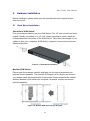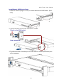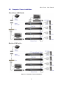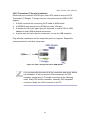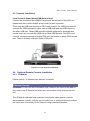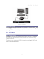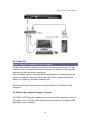
1
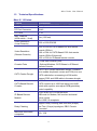
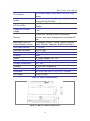
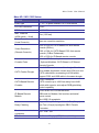
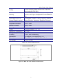
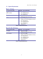
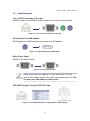
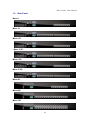
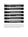
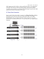
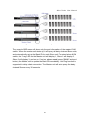
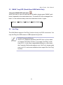
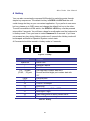
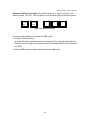
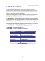
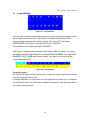
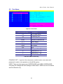
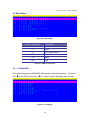
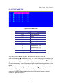
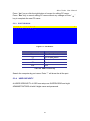
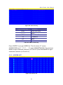
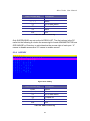
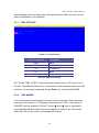
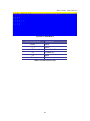
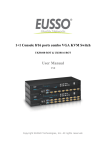
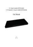
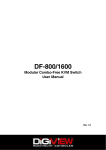
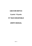
Mars Series Stand Alone & Modular CAT5 KVM Switch User Manual Rev 2.0 Mars Series User Manual Table of Contents Table of Contents ................................................................................................ I 1. Introduction .................................................................................................. 1 1.1 Features ............................................................................................. 1 1.2 Package Contents .............................................................................. 3 1.3 Technical Specifications ..................................................................... 4 1.4 System Requirements ........................................................................ 8 1.5 Cable Diagrams .................................................................................. 9 1.6 Rear Panel........................................................................................ 10 2. Hardware Installation................................................................................. 13 2.1 Rack Mount Installation .................................................................... 13 2.2 Computer / Server Installation .......................................................... 15 2.3 Console Installation .......................................................................... 17 2.4 Optional Remote Console Installation .............................................. 17 2.4.1 IP Module ............................................................................... 17 2.4.2 CAT5 Module ......................................................................... 18 2.5 Power ON......................................................................................... 19 2.6 When video signal is foggy or unclear.............................................. 19 2.7 Daisy Chain Connection ................................................................... 20 3 Usage ........................................................................................................ 22 3.1 Buttons (Stand Alone KVM Switch Only) .......................................... 22 3.2 Front Panel PC Port LED Indication (Stand Alone KVM Switch Only)22 3.3 BANK 7-seg LED (Stand Alone KVM Switch Only)........................... 23 3.4 Hot Plug ........................................................................................... 23 4 Hotkey ....................................................................................................... 24 5 OSD (On Screen Display) ......................................................................... 26 5.1 Login Window ................................................................................... 27 5.2 Port Name ........................................................................................ 28 5.3 Main Menu .......................................................................................... 29 5.3.1 LANGUAGE ........................................................................... 29 5.3.2 PORT NAME EDIT ................................................................. 30 5.3.3 PORT SEARCH...................................................................... 31 5.3.4 USER SECURITY .................................................................. 31 5.3.5 ACCESS LIST ........................................................................ 32 5.3.6 HOTKEY ................................................................................. 33 5.3.7 TIME SETTINGS .................................................................... 34 I Mars Series User Manual 6. 7. 5.3.8 OSD MOUSE ......................................................................... 34 Troubleshooting ......................................................................................... 36 Certifications .............................................................................................. 37 II Mars Series User Manual 1. Introduction The Mars series CAT5 KVM switch can control attaching servers and computers from local or remote console. This KVM switch is loaded with features such as one local console port, plus one optional CAT5-based remote console port or one optional IP-based remote console Port, On Screen Display (OSD) Menu, Password security, Hot key Control, Push Button and Auto Scan Control. It has complete keyboard and mouse emulation for simultaneous PCs boot-up process. With the CAT5-based remote console port you can you remotely control servers and computers 1000 feet away. In other words, you can locate your monitor, keyboard and mouse up to 1000 feet away from the KVM switch. The built-in CAT5 transmitter synthesizes VGA monitor and keyboard/mouse signals, and transmit the signals to the remote CAT5 receiver over the popular LAN CAT5 cable. With the IP-based remote console port you can control one or many computers locally at the server site or remotely via the Internet using a standard browser. You can securely gain BIOS level access to systems for maintenance, support, or failure recovery over the Internet. Communication is secure via SSL encryption. 1.1 Features 8/16/32 ports CAT5 KVM switch (32 ports only for modular CAT5 KVM switch) Support full CAT5 interface on all computer ports for reducing KVM cable bulk Support one local console or plus optional one remote console (CAT5 or IP) CAT5 console up to 1000 feet away from KVM switch with superior auto-adjust RGB gain/delay control capability Support Microsoft Windows, Netware, Unix, and Linux Support iMAC, Power MAC and Sun Micro Systems with USB port No Software Required - easy PC selection via On Screen Display (OSD) Menu, Push Buttons, Hotkeys 1 Mars Series User Manual Provide various Hotkey (Scroll-Lock/ Cap-Lock/ Num-Lock/ Alt/ Ctrl/ Win) for switching computer port and other control functions, so Hotkey function can be used in various types of keyboards, and to avoid Hotkey duplicate problem Provide ACL (Access Control List) security function. Store up to 8 independent user accounts Hot Plug --- add or remove connected computers without powering off the KVM switch or computers Support two layers password security protection and search PC server name Plug-n-Play monitor support Keyboard status restored when switching computers Support Daisy Chain function with both Bus (8-layer) and Tree (2-layer) topologies 2 Mars Series User Manual 1.2 Package Contents Mars 8 / 16 Series: KVM Switch Unit 1 PCS User’s Manual CD-ROM 1 PCS Quick Setting Guide 1 PCS 12V DC Power Adapter 1 PCS Rack Mount Kit 1 SET KC-1515 Daisy Chain Cable (0.9 M) 1 PCS T-Dongle 2 PCS USB Adapter 1 PCS Table 1-1. Package Contents Mars 8D / 16D / 32D Series: KVM Switch Unit 1 PCS Quick Installation Guide 1 PCS LCD Console Mount Kit 1 SET Table 1-2. Package Contents 3 Mars Series User Manual 1.3 Technical Specifications Mars 8 / 16 Series: Feature Specification KVM Type 8 / 16 ports stand alone CAT5 KVM switch PC Port Connector RJ-45 PC Ports 8 / 16 Max. Distance (KVM switch -- Host) 40m (133 feet) Video Resolution (Local Console) 1600 x 1200 DDC2B Video Resolution (Remote Console) 1600 x 1200 for CAT5-Based 500 feet remote console (R-Box), 1028 x 1024 for CAT5-Based 1000 feet remote console.(R-Box Enhanced). 1600 x 1200 for IP-Based remote console Console Ports 1 Local USB Console, plus 1 Optional Modules: CAT5-Based or IP-Based Remote Console CAT5 Combo Dongle 3-to-1 CAT5 combo transmitter dongle. Combine three cables (keyboard, mouse and VGA) into one CAT5 cable before connecting to KVM switch. Support PS/2 and USB cable in the same dongle. CAT5-Based Remote Console RJ-45 Connector CAT5 console up to 1000 feet away from KVM switch with superior auto-adjust RGB gain/delay control capability IP-Based Remote Module RJ-45 8P8C for 10/100M Ethernet DB9 male for Modem, Null modem and serial power control Mini USB 2.0 receptacle Daisy Chaining Support Daisy Chaining with both Bus (8-layer) and Tree (2-layer) topologies, DB15 Female Connector Maximum connected computers 120 / 128 4 Mars Series User Manual PC selection On Screen Display (OSD) Menu, Hot Key, Push Button Hotkey Provide various Hotkey (Scroll-Lock/ Cap-Lock/ Num-Lock/ Alt/ Ctrl/ Win) PC Port LEDs 2x LEDs per PC port: Power (Blue), Online (Green) 7-seg LED for Bank display 1 set Security Provide ACL (Access Control List) security function, store up to 8 independent controllable PC lists Multilingual OSD (On Screen Display) control 8 languages (English, France, Germen, Spanish, Italian, Russian, Japanese, Simplified Chinese) Auto-Scan Intervals 5 ~ 99 Sec. Keyboard Emulation PS/2 or USB Mouse Emulation PS/2 or USB Housing Metal Power DC power adapter : DC 12V Operation Temperature 0 ~ 50℃ Storage Temperature -20 ~ 60℃ Humidity 0~95%, Non-Condensing Mechanical 19” Rack mount / 1U Dimension 442 x 140 x 44 mm / 17.4 x 5.5 x 1.7 inches Net Weight 3.0 Kg / 6.6 lbs Table 1-3. Technical Specifications Figure 1-1. Mars 8 / 16 Series Dimensions 5 Mars Series User Manual Mars 8D / 16D / 32D Series: Feature Specification KVM Type 8 / 16 / 32 ports modular CAT5 KVM switch PC Port Connector RJ-45 PC Ports 8 / 16 / 32 Max. Distance (KVM switch -- Host) 40m (133 feet) Video Resolution (Local Console) Base on console’s resolution Video Resolution (Remote Console) 1600 x 1200 for CAT5-Based 500 feet remote console (R-Box), 1028 x 1024 for CAT5-Based 1000 feet remote console.( R-Box Enhanced). 1600 x 1200 for IP-Based remote console Console Ports 1 Local USB Console, plus 1 Optional Modules: CAT5-Based or IP-Based Remote Console CAT5 Combo Dongle 3-to-1 CAT5 combo transmitter dongle. Combine three cables (keyboard, mouse and VGA) into one CAT5 cable before connecting to KVM switch. Support PS/2 and USB cable in the same dongle. CAT5-Based Remote Console RJ-45 Connector CAT5 console up to 1000 feet away from KVM switch with superior auto-adjust RGB gain/delay control capability IP-Based Remote Module RJ-45 8P8C for 10/100M Ethernet DB9 male for Modem, Null modem and serial power control Mini USB 2.0 receptacle Daisy Chaining Support Daisy Chaining with both Bus (8-layer) and Tree (2-layer) topologies, DB15 Female Connector Maximum connected computers 120 / 128 / 144 PC selection On Screen Display (OSD) Menu, Hot Key 6 Mars Series User Manual Hotkey Provide various Hotkey (Scroll-Lock/ Cap-Lock/ Num-Lock/ Alt/ Ctrl/ Win) Security Provide ACL (Access Control List) security function, store up to 8 independent controllable PC lists Multilingual OSD (On Screen Display) control 8 languages (English, France, Germen, Spanish, Italian, Russian, Japanese, Simplified Chinese) Auto-Scan Intervals 5 ~ 99 Sec. Keyboard Emulation PS/2 or USB Mouse Emulation PS/2 or USB Housing Metal Power DC power adapter : DC 12V Operation Temperature 0 ~ 50℃ Storage Temperature -20 ~ 60℃ Humidity 0~95%, Non-Condensing Mechanical For modular LCD console use / 1U Dimension 420 x 170 x 44 mm / 16.5 x 6.7 x 1.7 inches Net Weight 2.0 Kg / 4.4 lbs Table 1-4. Technical Specifications Figure 1-2. Mars 8D / 16D / 32D Series Dimensions 7 Mars Series User Manual 1.4 System Requirements Mars 8 / 16 Series: CAT5 KVM Host side T-dongle – CAT5 transmitter Local Console side (USB console) IP module CAT5 module One VGA Monitor One USB Keyboard One USB Mouse One CAT5 cable Network access environment One CAT5 cable R-Box (CAT5 KVM extender receiver) One VGA Monitor One USB Keyboard One USB Mouse Optional PC Table 1-5. System Requirements Mars 8D / 16D / 32D Series: CAT5 KVM Host side IP module T-dongle – CAT5 transmitter CAT5 module One CAT5 cable Network access environment One CAT5 cable R-Box (CAT5 KVM extender receiver) One VGA Monitor One USB Keyboard One USB Mouse Optional PC Table 1-6. System Requirements 8 Mars Series User Manual 1.5 Cable Diagrams 3-in-1 CAT5 Transmitter (T-Dongle) HDDB15 male to one HDDB15 male and two mini din 6-pin special cables Figure 1-3. 3-in-1 Cat5 Transmitter (T-Dongle) PS/2 Keyboard to USB Adapter PS/2 keyboard to USB keyboard and mouse due HID adapter Figure 1-4. PS/2 Keyboard to USB Adapter Daisy Chain Cable: HDDB-15 pin Male to Male Figure 1-5. Daisy Chain Cable Daisy chain needs the cable all 15 lines connected. This is a special VGA cable, normal VGA cable has unconnected lines. Do not use other VGA cable for daisy chain. CAT5/5E/6 Straight Through UTP/STP Cable Figure 1-6. CAT5/5E/6 Straight Through UTP/STP Cable (8P8C) 9 Mars Series User Manual 1.6 Rear Panel Mars 8: Mars 16: Mars 8 IP: Mars 16 IP: Mars 8 C5: Mars 16 C5: Mars 8D: Mars16D: Mars 32D: 10 Mars Series User Manual Mars 8D IP: Mars 16D IP: Mars 32D IP: Mars 8D C5: Mars 16D C5: Mars 32D C5: Figure 1-7. Rear Panel The Mars KVM switch is designed as one control two views, both local console and remote console can access and view the same computer port, but only one console control at a time. These two consoles are operating on first come first served basis. If the controlling console does not have keyboard or mouse activity for 2 seconds, the other console may take over the control right. 11 Mars Series User Manual Mars 16 C5: Local Console Keyboard / Mouse Ports Local Console VGA Port / Daisy Chain Port Connector for Each Host Port Daisy Chain In DC Power Jack Remote Console Port (CAT5 Module) Mars 32D C5: Remote Console Port (CAT5 Module) Connector for Each Host Port Daisy Chain In DC Power Jack Figure 1-8. Rear Panel 12 Mars Series User Manual 2. Hardware Installation Before installation, please make sure all of peripherals and computers have been turned off. 2.1 Rack Mount Installation Stand Alone KVM Switch: Find a convenient place to put your KVM Switch. The 19” rack mount form factor makes it ideally mountable on a 19” rack. When mounting to a rack, attach the included brackets to the sides of the KVM Switch. Take note of the length of your cables so that your computers, KVM Switch, keyboard, mouse and monitor are distanced properly. Figure 2-1. Rack Mount Installation Modular KVM Switch: Please open the package carefully and take out all required accessories to prepare fluent installation. The modular KVM switch is for Gemini and Unicorn use, please install the brackets with thumb screw. Please measure the suitable distance between KVM switch and computer, keyboard, monitor and mouse before installation. Figure 2-2. Modular KVM Switch Usage Diagram 13 Mars Series User Manual Install Modular KVM Switch Steps: 1. Install two screws (length = 6 mm) to combine bracket and KVM switch. (Both sides) 2. Push KVM switch into the rails from rear of console. Plastic rail of KVM switch Rear view of rail 3. Tight thumb screw of bracket up to fix KVM switch in console (Both sides) and finish installation. 14 Mars Series User Manual 2.2 Computer / Server Installation Stand Alone KVM Switch: Modular KVM Switch: Figure 2-3. Computer / Server Installation 15 Mars Series User Manual CAT5 Transmitter (T-Dongle) Installation Each Host port connector is RJ45 type. Use CAT5 cable to connect CAT5 Transmitter (T-Dongle). T-dongle has four connectors and an USB to PS/2 adaptor. 1. A RJ45 connector for connecting CAT5 cable to KVM switch. 2. A HDDB15 male connector for PC/Server video VGA port 3. A purple mini din 6-pin type a plug for keyboard, or with a PS/2 to USB adaptor for both USB keyboard and mouse. 4. A green mini din 6-pin type for mouse port, no use for USB computer. Plug all these connectors into the respective ports of computer. Repeat the same procedure for all other computers. Figure 2-4. PS/2 T-dongle and PS/2 to USB adapter It is recommended to power off all the computers and server before the installation. If we can not turn off the computer, for PS/2 computer, please plug in T-dongle connectors in the following order: firstly PS/2 mouse connector, secondly PS/2 keyboard connector, thirdly the VGA connector to the PC. 16 Mars Series User Manual 2.3 Console Installation Local Console (Stand Alone KVM Switch Only) Connect the monitor to the HDDB15 female port on the back of the KVM unit labeled with the monitor symbol at the Local Console connector. There may be USB local console or PS/2 local console. For USB local console, connect the USB keyboard to either one of USB local port and USB mouse to the other USB port. These USB ports are special designed for keyboard and mouse, and can not work with USB hub or other USB devices. For PS/2 local console, connect keyboard to purple PS/2 port and mouse to green PS/2 mouse port. There is a Daisy chain port under VGA ports. Figure 2-5. Local Console Installation 2.4 Optional Remote Console Installation 2.4.1 IP Module Please refer to “IP Module User Manual” for details. IP Remote Console Installation: Power off the KVM switch firstly. Remove the cover of the add-on slot, slide in the IP Module and make sure the module is fully inserted into the slot. The IP Module redirects local keyboard, mouse and video data to a remote administration console. It allows you to control one or many computers locally at the server site or remotely via the Internet using a standard browser. 17 Mars Series User Manual Figure 2-6. IP-Module Serial Power Control The IP Module comes with a serial port for connecting to any serial device, such as serial PDU to provide remote power control, such as power on, power off, and power cycle for the connected computers/servers. 2.4.2 CAT5 Module CAT5 Remote Console Installation: Power off the KVM switch firstly. Remove the cover of the add-on slot, slide in the CAT5 transmitter module and make sure the module is fully inserted into the slot. To extending your console up to 1000 feet away by connecting the CAT5 cable to the R-Box in the remote end. 18 Mars Series User Manual Figure 2-7. Connect to CAT5 Receiver (R-Box) 2.5 Power ON Check connections and plug in power supply Double check whether all cables/connectors are properly connected. You can check the color of keyboard and mouse connector to make sure the keyboard and mouse cables go to the correct ports. Plug the power supply to the KVM switch and plug the AC power plug into the electrical receptacle. Now you will see the LED of Port 1 (Stand alone KVM switch only) lights up, and hear a beep sound. Recommend Power ON sequence as follows: Monitor, KVM Switch, finally Computer. 2.6 When video signal is foggy or unclear The R-Box (CAT5 Receiver) enables user to access to the computer, server, or KVM switch up to 1000 feet (300 meters) away with superior auto-adjust RGB gain/delay control capability 19 Mars Series User Manual CAT5 cables has CAT5, CAT5e, CAT6 and STP/UTP types; If your application need high VGA resolution and long distance please select high end cables. It is highly recommended to use optimal CAT5 cable length to get the best video quality and not waste unnecessary CAT5 cable. 2.7 Daisy Chain Connection Use one end of daisy chain cable to connect to the Daisy Chain Port of Master KVM switch and connect the other end of daisy chain cable to the Local Console Port of the next Slave KVM switch. Please repeat the connection procedures for next Slave KVM switch. You can daisy chain up to eight banks in maximum. Figure 2-8. Stand Alone KVM Switch Daisy Chain Connection 20 Mars Series User Manual Figure 2-9. Modular KVM Switch Daisy Chain Connection The console OSD menu will show only the port information of the master KVM switch. When the master unit starts up, it will query all daisy chained Slave units, and automatically set up the Bank ID for each Slave unit. For stand alone KVM switch, the 7-seg LED on the Master unit will display 1, Slave 1 will display 2, Slave 2 will display 3, and so on. If not so, please reset (press “BANK” and port button) the Master unit to update the Bank ID immediately. Hot Plug function is supported in daisy chain connection. The Master unit will auto-query the daisy chained Slaves every 30 seconds. 21 Mars Series User Manual 3 Usage When you power on KVM switch, it will prompt a Login window waiting for user name and password. Please refer to “Hotkeys and OSD manual” for details. 3.1 Buttons (Stand Alone KVM Switch Only) The push Buttons 1~16 : You can simply switch to a port by pressing the corresponding button. For 16 ports KVM Switch, please press button 1 ~ 16 directly to select the port you want. After power on the KVM switch, all of console ports (Local or Remote consoles) will be linked to Computer port 1. 3.2 Front Panel PC Port LED Indication (Stand Alone KVM Switch Only) 8 Ports 16 Ports Figure 3-1. Front Panel PC Port LED Indication There are two LEDs for each port: “P” power: the Green LED on indicating a Computer is connecting to the port. Notice the PC99 Computer always power on the PS/2 ports even if the Computer is not power on, so the Green LED will turn on. “O” online: the Red LED on indicating the port has been selecting. The Red LED flashing if there is no Computer connected to the port. Press “BANK” button and the port button simultaneously will reset the KVM switch. 22 Mars Series User Manual 3.3 BANK 7-seg LED (Stand Alone KVM Switch Only) 7-Segment BANK LED Indication : When you want to view the next bank KVM switch, please press “BANK” push button repeatedly to the destination bank. The bank LED will be changed from bank 1 to the maximum daisy chain level and then to bank 1 again. Bank 1 3.4 Bank 2 Bank 3 MAX. BANK Hot Plug The KVM Switch supports “Hot Plug” function for any non-PS/2 connectors. You may Hot Plug the USB mouse or USB keyboard as you like. DO NOT hot plug PS/2 port. Some O.S. (Operation Systems) like SCO Unix or Linux does not support “Hot Plug” function. If you apply “Hot Plug” to this kind of O.S., it will cause unpredictable behavior or shut down the Computer. Before attempting to use “Hot Plug”, please make sure your O.S. and mouse software driver support the “Hot Plug” function. 23 Mars Series User Manual 4 Hotkey You can also conveniently command KVM switch by switching ports through simple key sequences. The default hot key is SCROLL LOCK and the user could change hot key as your convenient application. If you prefer to use some hot key, please go to OSD menu and change the default hot key to the other. To send commands to KVM switch, the SCROLL LOCK key must be pressed twice within 2 seconds. You will hear a beep for confirmation and the keyboard is in Hotkey mode. Then you have to enter Command in 2 seconds. If you have not pressed any key during Hotkey mode over 2 seconds the Hotkey mode will be escaped and back to Operation System control state. A Command should be issued in Hotkey mode in 2 seconds. Scroll Lock Space Bar Scroll Lock Figure 4-1. Hotkey Command Function Space bar Active OSD ↑ Previous Channel ↓ Next Channel [1.2,…,8] bank, [01,02,…,32] port First digit bank number start with 1 Second and third digits port number start with “01” PgUp Previous bank PgDn Next bank “B” Turn on / off beeper “S” Auto Scan “U” Console Security “ON” to “OFF” “P” User logout / login “R” “L” OSD setting back to factory default value Turn on / off power saving Table 4-1. Hotkey 24 Mars Series User Manual Example: hitting Scroll Lock twice then hitting key 1, key 0, and key 1 will switch to bank 1 port 01. The first port is local at bottom right at the back panel. Scroll Lock Scroll Lock 1 0 1 Figure 4-1. Hotkey Example There are two methods to activate the OSD menu. 1. Activate OSD by Mouse Hold the left mouse button press and release the Esc key will active the Port Display. Hold the right mouse button press and release the Esc key will active the OSD. 2. Active OSD by press Hotkey twice then press Space bar. 25 Mars Series User Manual 5 OSD (On Screen Display) On Screen Display Menu provides a menu driven interface to handle a Multilingual Menu, Access Security, Computers switching process, to name a PC name or server name, to set up the password/window display time and to search PC port name if you don’t remember it. It allows two console users to access the same PC and only one of users has been linked to this PC first, another user can only view the same PC. This OSD Menu has 3 tiers dialog window: 1. Login Window --- When powering on this KVM switch, it will prompt a login window and ask for user name and password. This KVM system can setup one SUPERVISOR and eight USERS. Before not setting up administrator user’s name and his password, none of administrator users could access OSD menu. When you login with Supervisor, please go to USER SECURITY to set up one new SUPERVISOR or USERS. SUPERVISOR can access all Main menu options. USER can access PORT NAME and PORT SEARCH for switching. 2. Port Name--- port switching using OSD 3. Main Menu--- 8 menus to operate this KVM switch MAIN MENU Function 01 LANGUAGE OSD language change 02 PORT NAME EDIT PORT NAME modification 03 PORT SEARCH quick searching by port name 04 USER SECURITY Change password 05 ACCESS LIST Define user access authority 06 HOT KEY Change Hotkeys 07 TIME SETTINGS Modify SCAN time interval 08 OSD MOUSE Modify OSD MOUSE speed Table 5-1. OSD Main Menu 26 Mars Series User Manual 5.1 Login Window Figure 5-1. Login Window Turn on local console monitor and power on by plug in the power adapter, there will be login window at screen. No input for username and password over 1 minute at login windows the monitor’s signal will be turn off. The default SUPERVISOR user name is all eight zero digits “00000000 “.. The password is all eight zero digits “00000000 “. . . After login on or port switch either by panel button, OSD or Hotkey, the screen will display the following information, one digit BANK NUMBER, two digit PORT NUMBER, PORT NAME and current Hotkey, any input or mouse move the screen will back to PC. S c r o l l L o c k Figure 5-2. Login Window Security Logout No input for username and password over 1 minute at login windows the console monitor’s signal will be turn off. At normal operation, no input from console keyboard or mouse over 10 minutes the KVM switch will turn off the screen display then go to Login Windows ask for user name and password. 27 Mars Series User Manual 5.2 Port Name Figure 5-3. Port Name OSD Function Key Description F1 Go to Main Menu F2 CONSOLE OFF F3 Previous Menu Enter Switch to Selected Port ↑/↓ Move Select PgUp Previous Bank PgDn Next bank Esc Quit 1 Show port 01 ~ 08 2 Show port 09 ~ 16 3 Show port 17 ~ 24 4 Show port 25 ~ 32 Table 5-2. OSD Function Key CONSOLE OFF – logout so the next person needs to enter user name and password in order to do operation on this KVM system USER: There are two type of user SUPERVISOR and USER. SUPERVISOR can setup the change the OSD settings at Main Menu. USER can do Port switch and Port Search only. 28 Mars Series User Manual 5.3 Main Menu Figure 5-4. Main Menu OSD Function Key Description Enter Select ↑/↓ Move F1 Go to Main Menu F2 Console off F3 Back Esc Exit Table 5-3. OSD Function Key 5.3.1 LANGUAGE The default language is ENGLISH. Moving the cursor by keyboard -- Up Arrow key “ ”or the Down Arrow key “ ”or mouse to select language as you need. Figure 5-5. Language 29 Mars Series User Manual 5.3.2 PORT NAME EDIT Figure 5-6. Port Name Edit OSD Function Key Description Enter Port Name Edit ↑/↓ Move F1 Go to Main Menu F2 Console off F3 Back Esc Exit 1 Show port 01 ~ 08 2 Show port 09 ~ 16 3 Show port 17 ~ 24 4 Show port 25 ~ 32 Table 5-4. OSD Function Key The first line bar is Bank number, following lines are port name list. Use Up Arrow key “ ”, Down Arrow key “ ” or OSD MOUSE to move. After you have selected the PC port already, you can either press the Enter” “Key, or Move the cursor to PC name double clicks the left button of mouse to switch the PC port immediately. Press PgUp key or PgDn key for selecting previous or next Bank. Press the Up Arrow key “ ” or the Down Arrow key” ” to select “system 02 “ and press Enter” ” key to switch current PC port to PC port 2, or moving cursor to SYSTEM 02 and double clicks the left button of mouse to switch current PC port to PC port 2. 30 Mars Series User Manual Press “ Ins” key or click the right button of mouse for editing PC name. Press “ Esc” key to cancel editing PC name without any change or Enter” key to complete the new PC name. ” 5.3.3 PORT SEARCH P O R T E N T E R S E A R C H X N A M E : _ _ _ _ _ _ _ _ _ _ Figure 5-7. Port Search OSD Function Key Description Enter Start Port Search F1 Go to Main Menu F2 Console off F3 Back Esc Exit Table 5-5. OSD Function Key Search the computer by port name. Enter “*” will show the all the port. 5.3.4 USER SECURITY At USER SERCURITY of OSD can setup one SUPERVISOR and eight ADMINISTRATORS all with 8 digits name and password. 31 Mars Series User Manual Figure 5-8. User Security OSD Function Key Enter →↑←↓ Description Enter user name Move F1 Go to Main Menu F2 Console off F3 Back Esc Exit Table 5-6. OSD Function Key Press “ENTER” key to get USERS list. The left column “S” means SUPERVISOR and “1”, “2”,“3”,…., “8” mean ADMINISTRATOR. The maximum NAME is eight characters maximum (A~Z and 0~9) and PASSWORD is eight characters maximum (A~Z and 0~9). 5.3.5 ACCESS LIST Figure 5-9. Access List 32 Mars Series User Manual OSD Function Key Description Enter Select →↑←↓ Move F1 Go to Main Menu F2 Console off F3 Back Esc Exit Table 5-7. OSD Function Key Only SUPERVISOR can set up the ACCESS LIST. The first column is the PC name list the following 8 column the access right of each ADMINISTRATOR use OSD MOUSE or Enter key to active/inactive the access right of each port. “X” means to disable access and “O” means to enable access. 5.3.6 HOTKEY Figure 5-10. Hotkey OSD Function Key Description Enter Select →↑←↓ Move F1 Go to Main Menu F2 Console off F3 Back Esc Exit Table 5-8. OSD Function Key 33 Mars Series User Manual Some keyboard may not equip with all the special keys. Make sure the key you select is available in you keyboard. 5.3.7 TIME SETTINGS Figure 5-11. Time Settings OSD Function Key Enter Description Save F1 Go to Main Menu F2 Console off F3 Back Esc Exit Table 5-9. OSD Function Key The “SCAN TIME: 10 SEC” means that scan interval from one PC port to next PC port. The default SCAN time is 10 seconds and the maximum scan time is 99 seconds, can not use number pad. Press “Enter” key to save SCAN TIME. 5.3.8 OSD MOUSE You can change the move speed of mouse cursor in his item. There are three levels you can choose in it. The fastest move speed is “FAST”, the second is “MIDDLE” and the slowest is “SLOW”. Using " ” and “ ” key on keyboard to move highlight bar and select what move speed you want to use. After press Enter Key, the mouse cursor move speed will change. 34 Mars Series User Manual Figure 5-12. OSD Mouse OSD Function Key Description Enter Save ↑/↓ Move F1 Go to Main Menu F2 Console off F3 Back Esc Exit Table 5-10. OSD Function Key 35 Mars Series User Manual 6. 1. 2. 3. 4. 5. 6. Troubleshooting No LED display Make sure the power adapter plugs in the KVM Switch. If the LED’s still won’t light, perform soft reset to KVM switch by press “BANK” button and last port button at the same time. Do the hard reset by unplug the power then plug in again. The computer boot up fine, but keyboard doesn’t work PS/2 keyboard or PS/2 mouse port is not designed for Hot Plug. USB mouse and keyboard can Hot Plug, but need to wait few seconds for Computer bus emulations. Don’t press any keys on the keyboard while the selected computer is booting up. Otherwise it might cause the keyboard error or keyboard is not detected at Host side. Make sure the keyboard works when directly plugged into the computer. Try a different keyboard, but use only 101, 102 or 104-key keyboard. The Mouse is not detected during PC boot up Make sure to plug in mouse first, then plug in keyboard. Make sure the USB or PS/2 mouse works when directly plugged into the computer. Avoiding moving the mouse or pressing the mouse buttons when switching ports. No video signal display on the remote monitor Please go to check all of VGA cables & connector and CAT5 cable & connector are firmly connected. Video signal is foggy or unclear on the screen Please check if the VGA connector connected firmly. Check if the VGA resolution is too high for the length of CAT5 cable being used. If the problem happened at VGA resolution, to shorten the CAT5 cable length or reduce VGA resolution. It is highly recommended to use “optimal CAT5 cable length” to get the best video quality and not waste unnecessary CAT5 cable. If the CAT5 Receiver is not connecting a local computer, please make sure the monitor is grounded properly. VGA resolution output mismatch with the monitor’s The KVM switch will provide DDC information to all the PC VGA board. If both the local console’s monitor and KVM switch are turned on before the 36 Mars Series User Manual PC boot up, or if the PC boot up faster then the KVM switch, the PC miss the DDC (Data Display Channel) information that causes the VGA resolution output mismatch with the monitor’s. In this case, please turn off the PC wait few minute then turn on again. 7. Certifications FCC This equipment has been tested and found to comply with Part 15 of the FCC Rules. Operation is subject to the following two conditions: 1. This device may not cause harmful interference 2. This device must accept any interference received. Include interference that may cause undesired operation. CE This equipment is in compliance with the requirements of the following regulations: EN 55 022: CLASS B. RoHS All contents of this package, including products, packing materials and documentation comply with RoHS. 37