1
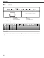
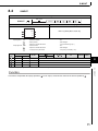
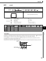
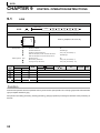
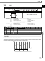
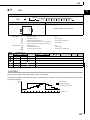
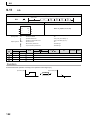
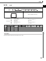
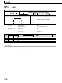
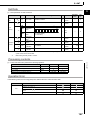
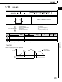
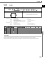
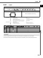
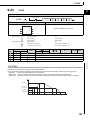
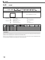
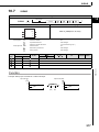
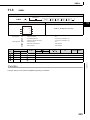
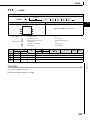
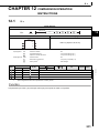
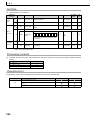
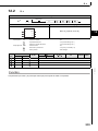
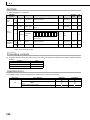
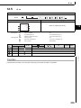
S.PHPL
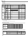
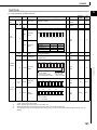
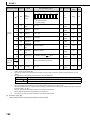
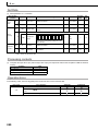
Set
Data
Block
diagram
9
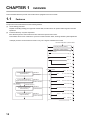
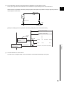
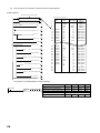
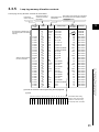
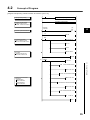
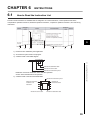
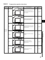
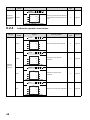
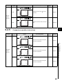
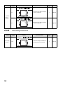
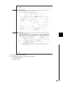
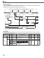
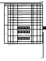
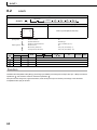
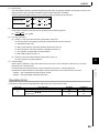
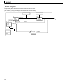
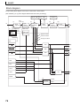
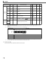
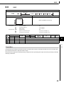
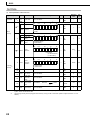
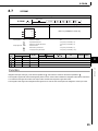
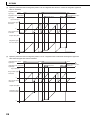
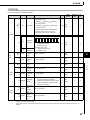
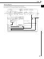
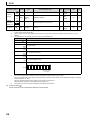
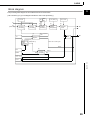
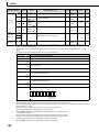
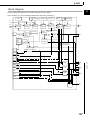
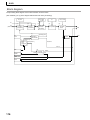
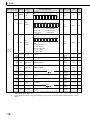
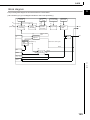
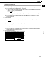
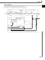
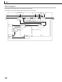
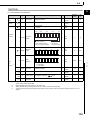
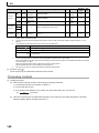
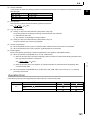
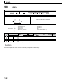
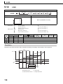
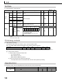
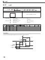
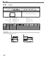
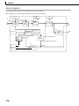
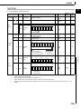
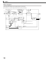
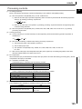
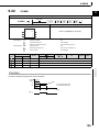
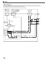
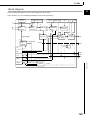
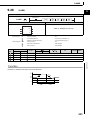
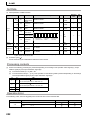
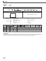
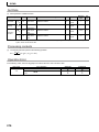
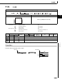
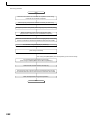
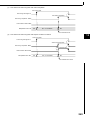
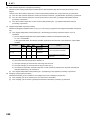
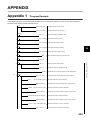
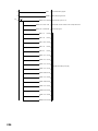
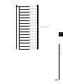
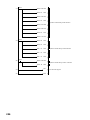
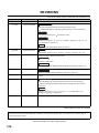
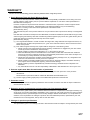
The processing block diagram of the S.PHPL instruction is shown below.
(The numerals (1) to (5) in the diagram indicate the order of the processing.)
RL, RH
LL
HH
PL
HS
PH
2
PV
DPL, CTIM
(1)
LL'
HH' PL'
(2)
E1
3
(4)
Engineering value reverse conversion
Engineering
value
conversion
PH'
4
(3)
Change rate
check
Upper/lower limit check
Upper limit alarm
Positive
Lower limit alarm
Upper upper limit alarm
Negative
BW
4
BB2
AND
6
Lower lower limit alarm
RUN(SPA 0)
(5)
Loop stop
judgment
BB3
AND
STOP(SPA 1)
7
AND
SPA
8
AND
(5)
BW
OFF
BB4
AND
PHI
ERRI
PLI
ERRI
HHI
ERRI
LLI
ERRI
DPPI
ERRI
DPNI
S.PHPL
BB5
AND
ERRI
9.8
Loop stop
processing
OR
BB1
PHA
PLA
HHA
LLA
DPPA
DPNA
143