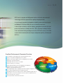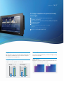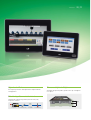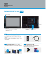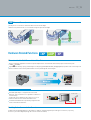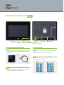
1
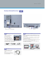
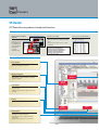
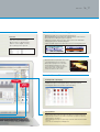
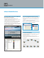
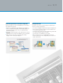
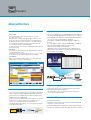
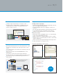
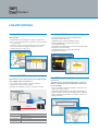
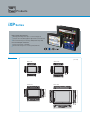
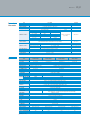
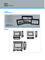
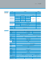
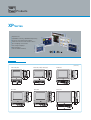
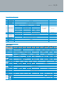
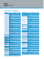
Human Machine Interface
XGT Panel
Leading Innovation,
Creating Tomorrow
XGT Panel
02_03
LSIS creates the core automation solutions for the fields ranging
from production facilities to information systems.
It is the device and software operable using a designed screen for users to
monitor and control the operating status of given facilities and equipments.
Windows CE platform based XGT panel is a user-friendly solution, providing
convenient, clear and realistic display, prompt data transmission and
processing as well as easy environments.
Based on the advanced technologies, LSIS satisfies various requirements
of clients, from unit facilities to advanced industrial fields, leading the HMI
market.
C O N T E N T S
XGT Panel
XGT Panel iXP Series
XGT Panel eXP Series
Products Line Up
Feature Hardware Related Functions
XP-Builder
Software Related Functions
Advanced Functions
Link with Controllers
External Monitoring Function
System Block Diagram
Our Solution
Products iXP Series
04
06
08
10
12
16
18
20
22
24
26
28
eXP Series
XP Series
30
32
34
List of Communication Drivers
36
XGT Panel
neXXt Generation Technology
We are in the forefront with advanced technologies for clients.
XGT Panel
XGT Panel is a brand new HMI product with an intensive and advanced
technology of LSIS to cope with the rapidly changing market.
It is an innovative product having both reliability and convenience based
on Window CE Platform. With the user-oriented convenience,
it offers high-resolution, realistic display, prompt data transmission and
processing and user-friendly interface. LSIS, offering a Leading Solution
in the automation field, proudly presents the XGT Panel series at the HMI
market with the advanced technologies and product quality, following the
XGT PLC.
Excellent Performance & Convenient Functions
Clear and high-resolution display with 16.7M TFT and 65K TFT colors
Various vector symbols and high quality raster symbols
Supports a wide range of graphic formats including BMP, JPG, GIF, WMF
Simple video clips with GIF drawing
10/100 BASE-T Ethernet interface as a default
Convenient and easy screen editing
Enhanced data management function (Logging, Recipe and Alarm)
Read function of the controller’s status information
(diagnosis, monitoring and maintenance)
Multi-lingual display of up to 12 languages and a batch language changing function
Offline simulation program (link with the XG5000 simulator)
HMI S/W tag function (easy to change the device address mapped to graphic objects)
USB Host/Device function for using various PC devices (mouse, keyboard, and etc.)
Sufficient memory space for project
Excellent performance and convenient functions
04_05
XGT Panel
iXP Series
intelligent XGT Panel
Convenient control with a single touch!
A user-oriented interface, enhanced performance, and
soft and quick screen switching and respond speed to touch!
Meet iXP series of LSIS that genuinely and fully connects
humans with equipments.
XGT Panel
06_07
It is highly competitive using the user-friendly
technologies.
Quick screen switching and response speed to touch
16.7M TFT colored LCD
Large drawing / backup memory (Drawing-128MB, Backup-1MB)
Sound Output support
Various interfaces
USB Host 3ch (Front: 1, Rear: 2), Device 1ch (Front)
SD card
Various communication drivers provided
Presence sensor applied (within 1m)
High Speed
Presence Sensor
High-performance 1GHz CPU is installed to improve the data and screen
switching speed, and Windows CE 6.0 Professional OS is adopted to
execute NET-based external applications.
Sensor detects movement within 1m, to control the backlight, ensuring
a longer life of the product.
More Colorful
Large Memory
High luminance/resolution LCD with an LED backlight and 24 bit colors
to express clear and vivid colors of 16,777,216.
Large device memory is provided to save mass data.
Storage space for screen
and images
Data backup space for
alarm and logging
128MB
1MB
512KB
10MB
XP
iXP
XP
iXP
XGT Panel
eXP Series
efficient XGT Panel
Effective Control and Monitoring Solution
Cost-Efficient eXP!
Simple Design
Large memory for drawing (64MB)
7” and 10.2” wide-screen sizes TFT color LCD
RTC function (maintained by battery)
Wide variety of communication interfaces
Convenient downloading/uploading
of drawings via USB port in the front
3-channel serial communication
Ethernet
XGT Panel
08_09
Higher Level of Performance
Slimmer and Lighter in Weight
Gives superior performance with improved CPU compared with the
existing products
20% lighter than previous products, provides more space and lightens
user’s panels
Wider Variety of Communication Interfaces
Communicable simultaneously with PLC, barcode reader, VFD,
temperature controller
PLC(Ethernet) + Barcode Reader(RS-232C) + Drive(RS485) + Thermostat(RS422)
Slim
Products Line-up
Window CE-based new HMI developed with advanced
technologies of LSIS to optimize the user experience
XGT Panel
15”(38Cm)
iXP Series
iXP90-TTA
12.1”(31Cm)
iXP80-TTA
Premium
Ethernet I/F
시리얼 I/F(RS-232C) 시리얼 I/F(RS422/485)
USB I/F
SD카드 I/F
TFT 16,777,216 colors
XGA(1024 768)
TFT 16,777,216 colors
SVGA(800 600)
10.4”(26Cm)
iXP70-TTA
TFT 16,777,216 colors
SVGA(800 600)
10.2”(25.9Cm)
eXP Series
eXP60-TTA
Standard
Serial I/F(RS-232C) Serial I/F(RS422/485) Serial I/F(RS-485)
USB I/F
TFT 65,536 colors
WVGA(800 480)
Ethernet I/F
15”(38Cm)
XP Series
XP90-TTA
12.1”(31Cm)
10.4”(26Cm)
XP80-TTA
XP70-TTA
TFT 65,536 colors
SVGA(800 600)
TFT 65,536 colors
VGA(640 480)
General
Ethernet I/F
Serial I/F(RS-232C) Serial I/F(RS422/485)
USB I/F
CF Card I/F
Expansion port
TFT 65,536 colors
XGA(1024 768)
XGT Panel
10_11
8.4”(21Cm)
iXP50-TTA
TFT 16,777,216 colors
SVGA(800 600)
7”(17.7Cm)
eXP40-TTA
eXP40-TTE *1
TFT 65,536 colors
WVGA(800 480)
8.4”(21Cm)
7”(17.7Cm)
5.7”(14Cm)
XP50-TTA
XP40-TTA
XP40-TTE *1 *2 *3
XP30-TTA
XP30-TTE *1 *2 *3
XP30-BTA
XP30-BTE *1 *2 *3
TFT 65,536 colors
VGA(640 480)
TFT 65,536 colors
WVGA(800 480)
TFT 65,536 colors
QVGA(320 240)
STN MONO (8-column Gray)
QVGA(320 240)
*1: Ethernet I/F not supported. *2: CF card I/F not supported. *3: Expansion port not supported.
Feature
Hardware Related Functions iXP
Presence Sensor
(Detects the body movement within 1m)
VM Module
Connector
Option
Card
Connector
SD Card
USB Host 1ch
USB(HOST)
10/100BASE-TX
(Connected to a USB memory, mouse and keyboard)
USB 2.0 Device
AUDIO OUT
RS-422/485
RS-232C
(Upload/Download of drawing)
iXP 1 Respective Front USB Host/Device Channel
An additional USB host channel is installed in the front panel.
A front USB host is used to connect to a USB memory, mouse and
keyboard.
A front USB device port is used to change the XP-Runtime without
opening a control panel or download/upload the drawing file created
using XP-Builder.
iXP Sound Output Function (For all iXP models)
The sound files (wav, mp3) registered using XP-Builder can be output
to speakers connected to HMI.
An alarm is generated via speakers to warn operators.
Up to 512 sound files can be saved.
An error
occurred
An alarm is
turned on
Sound files:
max. 512 files
PLC
iXP
Speaker
Front USB port
iXP Function to use SD Cards
iXP supports additional SD memory cards along with previous
USB memory to diversify the backup means.
Additional
XGT Panel
12_13
iXP Presence Sensor (For all iXP models)
The XP presence sensor detects movement within 1m to turn on a backlight.
When not used, it turns OFF the screen to maintain a longer lifespan of the backlight.
1m
Detection of lateral
movement
Detection of
movement
Up/Down 50 degrees,Left/Right 70 degrees
(Infrared ray 5 ~ 20 microns detected)
Hardware Related Functions iXP
eXP
XP
Ethernet method for Quick Transmission of Mass Data
Ethernet method has improved the transmission speed. Compared to the conventional RS-232C method, a quicker transmission speed:
115kbps 10/100Mbps
Regardless of the memory capacity, the drawing files can be quickly uploaded/ downloaded, and logging/alarm/recipe data can be conveniently used.
Ethernet method is used for various production data collection, monitoring and control using PC.
Barcode Scanner Communication
ASCII data imported by accessing a barcode scanner from
XGT Panel can be saved in the user-assigned PLC or XGT Panel’s
internal memory.
Complete Bit can be randomly saved. It allows users to check
whether the XGT Panel has read the data without errors.
Communication with barcodes is possible by using the RS-232C
interface installed in the XGT Panel.
Barcode Reader
PLC
RS-232C
Providing Various Communication Channels
Using RS-232C, RS-422/485 and Ethernet, XP and iXP are capable of communicating with up to 4 and 6 types of controllers, respectively.
Refer to the system block diagram (TTE type does not have an Ethernet module).
Feature
Hardware Related Functions eXP
USB 2.0 Device
USB Host 1ch
(Upload/Download of drawing)
(Connected to a USB memory,
mouse and keyboard)
RS-422/485
RS-485
10/100BASE-TX
RS-232C
eXP USB Port in the Front for Devices
eXP RTC Function
With USB port in the front, no need to open the control panel to apply
changes to XP-Runtime or download/upload drawing files made in
XP-Builder
RTC (Real Time Clock) function operates with a battery even with the
power off
HMI time setting is adjustable quickly using XP-Builder
Front USB port
eXP High Performance and Cost-Efficient
30% high performance and low cost
Performance
Price
eXP 3-Channel Serial Communication
Simultaneously communicable by RS-485, RS-232C, RS-422/485
D-Sub 9-pin terminal includes COM1 and COM2
XP
eXP
XP
eXP
XGT Panel
Hardware Related Functions
14_15
XP
RS-422/485
USB Host
CF card: effective use of USB memory
RS-232C
XP USB Host
Ethernet
XP Effective Use of USB Memory
2 USB interface channels
Various access devices can be
used using the USB I/F.
Access to mouse, keyboard,
a USB external hard disk, barcode
reader and USB hub is possible,
Access to mouse, keyboard, a USB
external hard disk, barcode reader
and USB hub is possible. Continuous upgrades and developments
to cope with other drivers are under progress.
PLC data can be saved in a CF card or USB memory. If necessary,
they are converted into a CSV format to be used to prepare daily and
monthly reports.
When the drawing files using XP-Builder are saved in a CF card or a
USB memory and copied to the XGT Panel, they can be executed
without being sent via cables.
When there are several XGT Panels, one CF card or USB memory can
be used to copy each XGT panel, allowing a setup.
A CF card or a USB memory can be used for engine updates and
upload/download of drawing files.
Project File (Memory Stick)
USB Hub
XP
A type
Keyboard/Mouse
USB Cable (XPO-USBC)
USB cable is used for screen data
transmission and XP-Runtime
updates.
The versions before XP-Builder 1.30
are not installed with the USB driver,
thus it must be installed.
USB External Hard Disk
Feature
XP-Builder
XGT Panel offers easy and user-friendly multi-interface.
XP-Builder Functions
Implementation of multiple
programs
In order to use the
previously created
drawing data for a
new drawing, more
than 2 XP-Builder
programs are
executed
simultaneously.
Function to check data
Cross-reference function of devices
•To check for any error on the data created,
and errors can be corrected by clicking on
them.
•The specific description of error created
is displayed.
Devices used for drawing data
and tags are displayed.
Drawing Editor: XP-Builder
Project Window
Aligned for easier addition and edition of project
view screens and special functions.
Data Element Window
Property
Window
•Displays the objects on a screen currently shown.
•When double-clicked, a window on setting the
properties appears.
Project
Window
Output Window
Screen Edit
•Displays the error checked on drawing data and the
search results.
•It displays the specific description of the errors
created.
Tool Box
Used to select an object or draw a shape.
Data
Elements
Library Window
•Library is divided by category for easier use,
and preview is used for drawing.
•Convenient for users to register and delete
the Library.
•Drag & Drop is used for a screen insertion.
Output
XGT Panel
16_17
Various fonts with convenient setting options
Tag function
•Users can set device address by desired
name, which can be used in an object.
•When a set device is tagged to an object,
addresses can be changed, collectively
•Windows fonts used in a PC can be transmitted to HMI for use.
•When using Windows fonts, font attributes (Italic, bold and underline) can be used as well.
•Various font sizes including True Type are supported.
•Supports the Unicode, characters of other countries such as the standard font
and high-quality fonts are beautifully displayed.
•Sophisticated and elegant text can be used to create a screen using various fonts.
•Up to 10,000 tags can be registered.
Animation function
•When GIF format is used, animation effects can be
realized depending on the state of given bit.
•When a video clip on given site is created into
GIF to be added to a drawing screen, more
accurate information can be delivered to users.
(Video clip files can be created using the
commercial software for GIF creation)
Video Clip GIF
User-oriented screen UI
Providing a flexible script language
Tool Box
Library
Window
•Provides a screen UI that can be easily used considering user’s experiences.
•Divided into categories so that a graphic library can be easily searched.
•Various graphic libraries are offered for enhanced usability.
Property Window
This function enables users to change properties of numerous objects at once, so
that users do not have to open each object like a button or a lamp for modification.
•Numerous objects on the screen can be selected at once to replace the pictures,
enhancing users' convenience.
•When modifying several objects, only the objects with the same function should be
selected.
•Users can correct both pictures and properties.
Feature
Software Related Functions
Multi-lingual support & conversion to respond to the
global enterprise environments
In response to enterprise environment of global era, up to
12 languages can be simultaneously converted and users can select
a language depending on his/her nationality.
When desired character string is registered in a table, a language
can be converted into a device value and switched upon operation.
The languages supported include Korean, English, Chinese
(PRC/Taiwan), Japanese, French, Turkish, Iranian (Persian), German,
Greek, Russian, Italian, Norwegian, Polish, Portuguese and Spanish,
all of which are supported in Windows.
Strict control management using security setting
Upon PLC control using objects like a switch or an input method editor,
only the authorized users can perform controls depending on the set
security level.
It supports 10 security levels in total, and the password of a sub-level
can be accessed using the password of a main level.
When the security level is authorized, a session is disconnected after a
certain period of time, asking for the password again.
Free and easy moving of parts
The fixed values and the parts related to the word device are selected/
switched to be displayed on a screen, and the images registered as
the given parts can be used.
A mouse is used to set the movement points for free moves,
linear moves, and moves based on the XY coordinates, which can be
chosen by users.
Free moves
3
2
4
1
5
Linear moves
1
2
3
4
5
XGT Panel
18_19
Automatic registration of a character string table
Memo pad function
This function enables the character string input by users in the objects
to be automatically registered.
Function to create or save a short message by selecting various pen
thicknesses and colors on XGT Panel.
When the file created using a single language is to be changed to a
character string table for the purpose of multi-lingual support, it can
be automatically registered to the character string table without
inconvenience of users.
All the static strings used in objects can be registered in the character
string table.
Up to 10,001 character strings can be added to a character string table,
and the name of a new character string table and the editing
languages can be set and registered by users.
Select “Automatic registration of strings
to the table” from the [Tool] menu
It is useful in exchanging messages between operators working in turns.
The user chooses the thickness and color of the pen and writes on a
screen in order to input the message.
Such memo can be saved in a CF card or a USB memory, and the data
are archived even when the power is turned off.
Users touch the screen and drag to create a memo.
When creating a memo, users can UNDO/REDO the memo, the
thickness/color of a pen can be changed, and a specific memo or all
memos can be deleted.
Feature
Advanced Functions
Alarm Function
Logging Function
History Alarm
The history of alarms can be saved in the device to check the
description of occurrence.
The alarm can be categorized into up to 8 upper and 8 lower class
groups or an alarm list, and an alarm explorer can display only the
group alarms the user may desire. When a screen on description to
check the details of alarms generated is registered, the detailed
screen window linked to the alarm will appear.
(It can be used to check the measures or detailed description when an
alarm is generated.)
Flow Alarm
The alarm generated is displayed on the upper/mid/lower section for
users to promptly take actions.
Flow alarm can be set to be operable at a specific screen, so it can be
used to deliver the information on equipments and company.
System Alarm
When a serious fault or a trouble of HMI occurs, the system alarm
informs the users, which is a critical function.
It offers a cyclic logging that is repeated depending on the time and device
state and a conditional logging which works under the device conditions.
Up to 32 logging areas (conditions) can be provided, and the maximum
size of an area can be set up to 512Kbyte, 100DWord.
Up to 512Kbyte, 100DWord (64Bit upon bit logging) per logging can
be saved.
Basically, logging is saved in the built-in SRAM(512Kbyte, 100DWord),
and the backup of logging is available using the CF card,
USB memory stick or USB external hard disk.
Logging data can be viewed in XGT Panel using a logging view object,
and they can be converted into a CSV format to be easily edited using
a PC via software such as EXCEL.
History Alarm
System Alarm
Alarm Explorer
Flow Alarm
PC reads the CF
card data.
Detail Screen Window
PLC
Encryption of Logging/Alarm Backup Files
E-mail Function
It offers a function to send backup files (.csv) using the E-mail address
registered upon backup of the logging and alarm data in XGT Panel.
The E-mail function for logging can only send the backup files of the
group desired for each logging group.
The E-mail function for history alarm includes a function to send to the
E-mail only on the alarm messages to the designated receivers
when the user-assigned alarm is generated or recovered.
The logging and alarm backup files sent can be easily analyzed in PC
using a program like EXCEL.
An alarm has
occurred!!
The backup file format can be archived as binary files to prevent the
data from being damaged or manipulated.
The encrypted files can be converted into CSV files using a CSV file
converter offered from XP-Builder.
Able to View PDF
Viewing PDF file XGT Panel
Saving trouble shooting instructions for failures (alarm) in PDF format
so that users could see in the field
No number limit of PDF files as PDF files are saved in external memories
This function is available only in iXP series HMIs, not in XP series HMIs
XGT Panel
20_21
Script
Scheduler
Scheduler assigns an operation to be executed on a set time.
Available functions include Bit ON/OFF, setting Word values and a
script operation. Each scheduler can assign up to 8 operations.
Up to 32 schedulers can be set.
Write
Providing a flexible script language
It is difficult to perform drawing using only the provided object functions,
and it can be supplemented using a script.
A structured language similar to the C language is used for user’s
convenience.
The script using complicated arithmetic operations and various functions
is executed to greatly reduce the load upon external controllers.
A validity check of the grammar on the created scripts is available.
Various uses of scripts
A wide range of scripts including global scripts, screen scripts and object
scripts can be used depending on the usage.
A global script operates according to ON/OFF of the device assigned,
regardless of the screen operation, and a special device can be used for
scripts in a regular basis.
An object script can perform operational management of the object devices.
A script can run when a screen opens or closes.
Convenient script tool box & script error check
Recipe
After the data to be written on PLC are created, the data values created
on a PLC device continuously connected to a specific device can be
written.
It can read a lot of device values from the PLC continuously connected
to a specific device.
Basic recipe can register up to 10000 Word/DWord devices and
255 table blocks.
Recipe data are saved in a non-volatile memory of XGT Panel.
Thus, when the power is out, the data saved at the last minute are kept.
Recipe data can be registered and edited using a XGT Panel or an
EXCEL program.
Data can be written with PLC on the internal
memory of XGT Panel, and they can be
imported from PLC to XGT Panel.
PLC
Can be edited in EXCEL
Simple &
Easy Editing
Data can be written and read in a non-volatile memory.
Feature
Link with Controllers
Convenient Simulator
Able to Link with PLC Simulator
Offline simulation
Without XGT Panel, the drawing data can be directly viewed from PC.
Devices can be monitored using a PC, and values can be directly input
to check operations.
A simulator is used to check the operations just like the XGT Panel.
Before transmitting the drawing data to HMI, data errors and
abnormal operations can be checked.
Controlling and monitoring testing in PC linking XP-Builder
(XP-Simulator) and PLC simulator
Linking with LSIS PLC simulator and XG5000 simulator
Linking with SIEMENS PLC simulator and S7-PLCSIM
(S7-PLCSIM v5.4 or above)
Linking with Rockwell Automation PLC simulator and RSLogix Emulate
5000 Controller (v21.00.00 or above)
Linking with Mitsubishi PLC simulator and GX Simulator
(GX Simulator v7.30 or above)
Simulator
Virtual Device Input
Simulator
XG5000 Simulator
Path-through(XP-VSP)
When XGT Panel is connected to PLC with serial, PLC ladder program
can be modified using the internal Ethernet.
Users no longer have to change the cable for PLC program
modification, or to go to the PLC for changes.
A program can be modified even when a control panel is far away.
Serial (CPU)
Note) XP-VSP user manual reference
Manufacturers
LSIS
Supported Drives
ALL LSIS PLC CPU
XGI/K Series Link(Only Remote-1 Connection)
Ethernet
Omron Corporation
CS/CJ Host Link Serial
YASKAWA
MEMOBUS RTU Master
Using XGT PLC for batch-registration of devices
(tag function)
The variable names used in the PLC program that is created using
XG5000 are automatically registered in XP-Builder, so that they can
be used in drawings.
[Save as a Variable/Description File] of XG5000 is used to first save the
variable names used as CSV files.
Using [Import XG5000 Symbols] from the [Tag] item of XP-Builder, an
automatic registration via tags is possible (Array variables supported).
Without changing the memory address, the variables used in the PLC
program can be used.
XGT Panel
22_23
Communication Options
RAPIEnet(XPO-EIMT) twisted-pair ring system diagram
Fieldbus option provided
Various Fieldbus communications using the XGT Panel
options
(RAPIEnet, Profibus-DP and CANopen Slave offered)
Note) An option module supports only XP (iXP to be supported in the future)
XP-Server Function
The data required from the production site’s XGT Panel can be directly collected or saved in a PC.
It has several roles including a mutual data exchange between several XGT Panels, or sending an E-mail or connecting to a Database.
It connects to the Database via PC to save, inquire and manage the XGT Panel data.
When a trigger condition is generated, users will be informed via data E-mail of PC.
When a trigger condition is generated, it imports or writes the screen capture, logging, alarm and recipe data of a specific XGT Panel.
It is possible to collect various information including production outputs and causes of errors and failures from the XGT Panel to the DB server
Database
Factory
Data
Ethernet
Data
Data
Data
Data
Feature
External Monitoring Function
※ Only the Ethernet-support models can use the function.
XP-Remote
An XGT Panel screen can be monitored and controlled remotely with a PC.
Up to 4 PCs can remote-access to a single XGT Panel. (Only one PC can access XP-VNC.)
Remote PC control of XGT Panels can be authorized or restricted (When not authorized, it is impossible to control with the Remote PC).
There is a synchronization mode and a non-synchronization mode, which allows users to monitor the XGT Panel and the Remote PC screen
under the same or different conditions.
XP 1
XP 2
XP 1
XP 2
XP 1
XP 2
HUB
XP 1
XP 2
Factory
Ethernet
XP n
XP 1
XP 2
XGT Panel
Web Server
The screen currently viewed on a XGT Panel can be viewed on a web
browser via Internet.
It is accessible in any place where Internet is connected.
It can be connected to multiple Internet Explorers.
(Impossible to access the XP screen at the same time)
It is possible to upload the logging and alarm backup files as
csv files in the XGT Panel.
It is possible to restrict access of specific users or groups.
Internet
※ The functions described above are available when a Web Server Program is installed
to the XGT Panel using XP-Manager.
XP-VNC
The screen currently shown in the XGT Panel can be viewed
from the user’s PC.
Several XGT Panels can be monitored and controlled with one PC.
After inserting the IP of XGT Panel to be accessed from XP-VNC
(S/W for PC), the current screen of the XGT Panel can be monitored and
controlled.
It is possible to restrict PC control when the XGT Panel is
under operation on site (VNC interlock device provided).
XP 1
XP 2
HUB
XP 1
XP 2
XP n
24_25
Feature
System Block Diagram
1 : 1 Serial/Ethernet Communication
One controller to one XGT Panel
※ In case of the 1:1 Ethernet communication, a cross cable should be used.
RS-232C
RS-422/485
Ethernet
N : 1 Serial Communication
One controller to multiple XGT Panels (serial)
※ Up to 16 XGT Panels can be connected, but the speed for screen
refreshing varies according to the number of panels.
※ Connection available only to specific controllers (limited to PLCs)
Only RS-485 available
Simultaneous connection with multiple
controllers
4 kinds of controllers to one XGT Panel
Ethernet
※ Without the RS-422/485 and RS-232C, up to 4 controllers can be
connected using only Ethernet.
※ When it comes to iXP, up to 16 controllers can be connected.
XGK
RS-232C
Master K
RS-422/485
GLOFA
XGI
XGT Panel
1 : N Serial Communication (Multi Drop)
Multiple controllers to one XGT Panel
※ When 1:N communication is applied, the same types of controllers should
be used.
RS-422/485, 500m Max
N:1 Ethernet Communication
One controller to multiple XGT Panels (Ethernet)
※ According to the controller type, the number of XGT Panels connected
may vary.
Ethernet
N:M Ethernet Communication
Multiple controllers to multiple XGT Panels
Ethernet
26_27
XGT Panel
28_29
Our Solution
We are leaping as a global leader beyond the top enterprise
in Korea in the field of automation solutions.
The LSIS HMI solutions incorporate the core H/W and S/W technologies and
services, which are optimized for client’s environments at various industrial
sites, ranging from unit machines to massive process control.
Products
iXP Series
High-resolution and performance
1GHz high-performing CPU & quick screen refreshing speed
16,777,216. TFT color (24bit) support & high-luminance/resolution LCD
Mass internal memory (User memory: 128MB, Data backup: 1MB)
User-oriented simple environment
Various storage interfaces (USB/SD)
Movement detection (presence sensor) system (within 1m)
Dimensions
[Unit: mm]
iXP70-TTA
iXP50-TTA
!
iXP90-TTA
!
!
iXP80-TTA
!
XGT Panel
General
Information
Item
Ambient Temperature
Storage Temperature
Ambient Humidity
Storage Humidity
Vibration resistance
Shock resistance
Vibration resistance
Description
0℃~+50℃
-20℃~+60℃
10~85%RH, without dew condensation
10~85%RH, without dew condensation
Occasional vibration
Counts
Frequency
Amplitude
Acceleration
5 ≤ f < 9㎐
3.5mm
9 ≤ f ≤ 150㎐
9.8㎨
10 times each direction
Continuous vibration
(X, Y and Z)
Amplitude
Frequency
Acceleration
1.75mm
5 ≤ f < 9㎐
9 ≤ f ≤ 150㎐
4.9㎨
Maximum shock acceleration: 147㎨(15g) * Authorization time: 11ms
* Pulse waveform: Half-sine wave (3 times each of X, Y and Z) *
Square wave impulse noise
Electrostatic discharge
Radiated electromagnetic field noise
Fast transient/Burst noise
Operating ambience
Altitude
Pollution degree
Cooling method
Specifications
Item
iXP50-TTA/DC
DC: ±1,200V AC: ±1,800V
±4kV (Contact discharge)
80 ~ 100MHz, 10V/m
Power Module: 2 kV, Communication Interface: 1kV
Free from corrosive gas and excessive dust
2,000m (6,562ft) or below
2 or under
Natural air-cooling
iXP70-TTA/DC
iXP70-TTA/AC
iXP80-TTA/DC
iXP80-TTA/AC
30_31
Standard
IEC 61131-2
IEC 61131-2
LSIS Standards
IEC 61131-2, IEC 61000-4-2
IEC 61131-2, IEC 61000-4-3
IEC 61131-2, IEC 61000-4-4
iXP90-TTA/DC
iXP90-TTA/AC
TFT LCD
Display type
21.3cm (8.4″)
26.4cm (10.4″)
30.7cm (12.1″)
38.1cm (15″)
Screen size
800×600 pixel(SVGA)
800×600 pixel(SVGA)
800×600 pixel(SVGA)
1,024×768 pixel(SVGA)
Display Resolution
16-bit and 24-bit Color (default: 16-bit Color)
Color indication
Left/Right: 80 deg. Up: 60 deg. Down: 80 deg.
Left/Right: 80 deg. Up: 80 deg. Down: 60 deg.
Indication degree
LED Type
Backlight
70,000 hours
60,000 hours
Backlight duration
Brightness
500 cd/㎡
700 cd/㎡
550 cd/㎡
800 cd/㎡
4-Line type, analog
Touch panel
Magnetic buzzer (85dB)
Sound Output
ARM Cortex-A8 Core (32bit RISC), 1GHz
Process
Flash
1GB(display 128MB)
512MB(display 128MB)
Memory Operating RAM
512MB
256MB
1MB
Backup RAM
Date/Hour data, Logging/Alarm/Recipe data and nonvolatile device
Backup data
Approx. 3 years (Operating ambient temperature of 25°…)
Battery duration
1 channel, 10/100BASE-TX
Ethernet
3 channels, USB 2.0 host (mouse, keyboard, printer* and USB memory driver is available)
USB Host
1 channel, USB 2.0 slave (for download and upload project file)
1 channel
RS-232C
1 channel, RS-422/485 mode
RS-422/485
1 Slot (SDHC)
SD Card
Detection range: side 1-1.5m, front 40-50cm
Human sensor
Angle: high/low 100°, left/right 140° (detecting 5-20 micron infrared light)
LINE-OUT 1 channel
Audio output
For communication and I/O option module (available later)
Expansion module
4 channels video input (available later)
VM module
Up to 12 language simultaneously
Multi-language
GIF format is available
Animation
available
Recipe
available
Data logging
available
Script executor
CE, UL(cUL), KC
Certifications
IP65
Protection standard
Dimension (mm)
240.5×180.0×54.4
270.5×212.5×60.0
313.0×239.0×56.0
395.0×294.0×60.0
Panel cut (mm)
228.5×158.5
259.0×201.0
301.5×227.5
383.5×282.5
DC24V
DC12/24V(AC 100-240V)
Rated voltage
Power consumption (W)
30.8
42.3
42.3
42.3
Weight(Kg)
1.9
2.2
2.4
3.9
SEWOO printer only
Products
eXP Series
TFT LCD-applied wide type
LED Backlight adopted for enhanced contrast ratio
and low-power
PLC Ladder monitoring function:
Only XGK/XBC supports*
Web Server* / Data Server* /
Path-Through Function*
Remote Viewer Function*
Screen editor : XP-Builder
Functions that support only the TTA model
Dimensions
[Unit: mm]
!
!
eXP60-TTA
!
eXP40-TTE
eXP40-TTA
XGT Panel
General
Information
Item
Description
Ambient temperature
0℃~+50℃
Storage temperature
32_33
Standard
-20℃~+60℃
Ambient humidity
10~85%RH, without dew condensation
Storage humidity
10~85%RH, without dew condensation
Occasional Vibration
Amplitude
Acceleration
Frequency
Vibration resistance
5 ≤ f < 9㎐
-
3.5mm
9 ≤ f ≤ 150㎐
9.8㎨
Continuous Vibration
-
Frequency
Acceleration
Amplitude
Counts
10 times each direction
(X, Y and Z)
IEC 61131-2
5 ≤ f < 9㎐
1.75mm
4.9㎨
Maximum shock acceleration: 147㎨(15g) Authorization time: 11㎳ Pulse waveform: Half-sine wave pulse (3 times each of X,Y and Z)
DC: ±1,200V
Square wave impulse noise
9 ≤ f ≤ 150㎐
Shock resistance
Noise resistance
Electrostatic discharge
±4kV (Contact discharge)
IEC 61131-2, IEC 61000-4-2
Radiated electromagnetic field noise
80 ~ 100MHz, 10V/m
IEC 61131-2, IEC 61000-4-3
Fast transient/Burst noise
Power module: 2.4 kV, Communication interface: 1.2kV
IEC 61131-2, IEC 61000-4-4
Free from corrosive gas and excessive dust
Operating ambience
2,000m (6,562ft) or below
Altitude
Specifications
Pollution degree
2 or under
Cooling method
Natural air-cooling
Item
Display Type
eXP40-TTE/DC
eXP40-TTA/DC
eXP60-TTA/DC
TFT color LCD
Display Size
17.7cm (7 inch)
25.9cm (10.2 inch)
800 x 480 (WVGA)
Resolution
Color
Display Angle
65,536 colors
Left/Right: 60 deg. Up: 40 deg. Down: 60 deg.
Left/Right: 55 deg. Up: 35 deg. Down: 55 deg.
LED mode, Auto On/Off
Backlight
20,000 hr
Backlight Capacity
230 cd/㎡
Brightness
200 cd/㎡
4-wire system, Analogue
Touch Panel
Magnetic buzzer (85dB)
Sound
ARM9 Core (32bit RISC), 454MHz
Processor
128MB(Screen 64MB)
Flash
Memory
IEC 61131-2
LSIS Standards
128MB
Operation RAM
128KB
Backup RAM
Backup Type
Date/Time data, Logging/Alarm/Recipe data, non-volatile device
Batter Capacity
Ethernet
USB Port
-
Around 3 years (Upon operation at 25℃)
1 channel, 10/100BASE-TX
1 channels, USB 2.0 host (mouse, keyboard, printer* and USB memory driver is available)
1 channel, USB 2.0 slave (for download and upload project file)
1 channel
RS-232C
1 channel
RS-485
1 channel, 422/485 Combination
RS-422/485
Up to 12 language simultaneously
Multi-language
GIF format is available
Animation
Recipe
available
Data logging
available
available
Script executor
Certification
CE, UL(cUL), KC
Protection
IP65
208.0 154.0 44.0
Size (mm)
276.0 218.0 44.2
192.0 138.0
Panel Cut (mm)
260.0 202.0
DC24V
Power
Power Consumption (W)
23.1
23.1
23.1
Weight (kg)
0.59
0.60
1.0
SEWOO printer only
Products
XP Series
65,536 TFT color
4/10/20MB User memory, 128/512KB Backup memory
Ethernet & serial communications support
USB Host function to be used in various PC devices
Up to 12 languages at a time and a
batch-change of languages
Offline simulations
(Link to the XG5000 simulator)
Dimensions
[Unit: mm]
XP30-TTA / TTE
XP70-TTA
XP40-TTA / TTE (7”wide Type)
XP80-TTA
XP50-TTA
XP90-TTA
XGT Panel
34_35
General Information
No.
1
2
3
4
5
Item
Ambient temperature
Storage temperature
Ambient humidity
Storage humidity
Vibration Resistance
Frequency
5 ≤ f < 9㎐
9 ≤ f ≤ 150㎐
Frequency
5 ≤ f < 9㎐
9 ≤ f ≤ 150㎐
6
Shock Resistance
7
Noise Resistance
8
9
10
11
Operating ambience
Altitude
Pollution degree
Cooling method
Description
0℃~+50℃
-20℃~+60℃
10~85%RH, without dew condensation
10~85%RH, without dew condensation
-20℃~+60℃
Acceleration
Amplitude
3.5mm
9.8㎨
Continuous Vibration
Amplitude
Acceleration
1.75mm
4.9㎨
Standard
Counts
10 times each direction
(X, Y and Z)
Maximum shock acceleration: 147㎨(15g) Authorization time: 11㎳ Pulse waveform: Half-sine wave pulse (3 times each of X,Y and Z)
Square wave impulse noise
AC: ±1,500V DC: ±1,000V
Electrostatic discharge
Voltage: 6 kV (Contact discharge)
Radiated electromagnetic field noise
27 ~ 500MHz, 10V/m
Fast transient/Burst noise
Power module: 2 kV, Communication interface: 1kV
Free from corrosive gas and excessive dust
2,000m (6,562ft) or below
2 or under
Natural air-cooling
IEC 61131-2
IEC 61131-2
LSIS Standards
IEC 61131-2, IEC 61000-4-2
IEC 61131-2, IEC 61000-4-3
IEC 61131-2, IEC 61000-4-4
Specifications
Model Type
Display Element
Screen Size
Resolution
Color
Backlight
XP30-BTE/DC XP30-BTA/DC XP30-TTE/DC XP30-TTA/DC XP40-TTE/DC
XP40-TTA/DC XP50-TTA/DC
Mono
Mono Blue LCD
14cm (5.7”)
320×240
8-column Gray Scale
256 colors
65,536 colors
LED mode
17.7cm (7”)
800×480
XP70-TTA/AC XP80-TTA/AC
XP70-TTA/DC XP80-TTA/DC XP90-TTA/AC
Color
TFT color LCD
21cm (8.4”)
26cm (10.4”) 31cm (12.1”)
38cm (15”)
640×480
800×600
1024×768
65,536 colors
CCFL(can be replaced), Auto On/Off
60,000 hours
50,000 hours
Fixed
480cd/㎡
430cd/㎡
400cd/㎡
450cd/㎡
50,000 hours
60,000 hours
30,000 hours
Adjustable
Contrast
230cd/㎡
600cd/㎡
280cd/㎡
Brightness
80/80
20/40
70/70
50/60
50/60
45/65
45/75
60/50
Viewing Up/Down(Degree)
Angle Left/Right(Degree)
80/80
45/45
65/65
65/65
65/65
65/65
75/75
8-wire system, analogue
Touch Panel
4-wire system, analogue
Analog resistive
Green: Normal RUN (Monitoring & drawing data download) Red: Error (Communication error & drawing data error)
Movement LED
Screen Data
10MB
10MB
4MB
10MB
4MB
4MB
10MB
20MB
Memory
512KB
512KB
512KB
128KB
Backup Data
128KB
128KB
1ch, 10/100Base-T
1ch, 10/100Base-T
1ch, 10/100Base-T
Ethernet
USB Host X 1
USB Interface
USB Host X 1 USB Host X 2 USB Host X 1 USB Host X 2
USB Host X 2
2ch(1 port for PC communication)
RS-232C
Serial
1ch, 422/485 optional mode
RS-422/485
CF card (TAPE-1)×1
CF card (TAPE-1)×1
CF card (TAPE-1)×1
CF Card Interface
Optional
Optional
Optional
AUX Interface
Certification
CE, UL, KC
Protection
IP65 (Front Water Proof Structure)
Size(W×H×D)mm
203.5 x 153.5 x 41.5
240 x 174 x 73
317 x 243 x 73
395 x 294 x 73
181 x 140 x 56.5 181 x 140 x 66.5 181 x 140 x 56.5 181 x 140 x 66.5
Panel Cut (W×H)mm
192 x 138
228.5 x 158.5
294.5 x 227.5
383.5 x 282.5
155.0 x 123.5
Weight (kg)
3.9
2.2
2.2
2.4
2.4
1.4
0.75
0.62
0.75
0.62
Rated Voltage
AC100~220V
DC 24V
AC100~220V, DC 24V
MIN 85 VAC, MAX 264 VAC
Permitted AC
DC
MIN 19.2 VDC, MAX 28.8 VDC
Power Voltage
Power
31.9
AC
21.8
31.9
Consumption
20.1
25.7
9.7
16.9
17.4
9.8
9.8
18.7
DC
9.6
(W)
Products
List of Communication Drivers
Manufacturer
Driver name
GM CPU
GM Cnet
GM Enet
MK CPU
MK Cnet
MK Enet
XGK CPU
XGK Cnet
XGK Enet
XGK EtherNet/IP
XGB CPU
XGB Cnet
XGB Enet
LSIS
XGB EtherNet/IP
XGI/XGR CPU
XGI/XGR Cnet
XGI/XGR Enet
XGI/XGR EtherNet/IP
XEC CPU
XEC Cnet
XEC Enet
XEC EtherNet/IP
Inverter LSBus
Inverter Modbus
User Defined Protocol
User Defined Protocol (Slave)
XGT Servo
VS/VP Servo Drive
LS Mecapion
MXQ Series
BACnet
IP Master
BYD Auto
BYD Auto dedicated
CAN in Automation CANopen Slave
Control Techniques CT Modbus RTU
DAEWON GSI
DAEWON GSI dedicated controller
Dasarobot
iM-SIGMA series
Delta Electronics
DVP Series
Digital Electoronics(Pro-face) Memory Link
MICREX-SX Series SIO
Fuji Electric
Systems
MICREX-SX Ethernet
SNP
GE Intelligent
Platforms
SNP-X
Temperature Controller
HANYOUNG NUX
Servo
HIGEN Motors
H Series Ethernet
Hitachi
H Series Link
SKY-RAV(Ethernet)
HYUNDAI Elevator
SKY-RAV(Link)
CIMON Serial Link
BP Series Loader
KDT Systems
CP Series Loader
XP Series Loader
KV-700/1000/3000/5000/5500 Serial
KEYENCE
KV-700/1000/3000/5000/5500 Ethernet
Manufacturer
KOYO Electronic
KTURBO
Lenze Automation
Driver name
DirectNet
Turbo Blower
Lecom A/B
MELSEC A-CPU
MELSEC A-Link
MELSEC FX-CPU
MELSEC FX-Ethernet
MELSEC FX-Link
MELSEC Q-CPU, “U” Type excluded
Mitsubishi Electric
MELSEC QnA-Link
MELSEC QnA-Ethernet
MELSEC QnU CPU Ethernet
MELSERVO-J2
MELSERVO-J3
CS/CJ Series Ethernet
CS/CJ Host Link
OMRON
C Series Host Link
CS1 EthernNet/IP
CJ2 EthernNet/IP
FP Series
Panasotic Electric
MINAS Servo
Hi-Drive
Parker
PROFIBUS International PROFIBUS DP Slave
Compact/ControlLogix EtherNet/IP
MicroLogix EtherNet/IP
Rockwell Automation
SLC500 Series DF1
Compact/ControlLogix DF1
MicroLogix DF1
N/NX-CCU
RS Automation
NX-CCU+
MODBUS RTU Master
MODBUS RTU Slave
MODBUS TCP Master
Schneider Electric
MODBUS TCP Slave
MODBUS ASCII Master
MODBUS ASCII Slave
SEW EURODRIVE
MOVIDRIVE Serial
S7 3964(R)/RK512
S7 MPI(Adapter)
S7 PPI
Siemens AG
LOGO Ethernet
S7 1200 Ethernet
S7 300/400 Ethernet
Sprint Electric
DC Motor Drive Ethernet
MEMOBUS RTU Master
YASKAWA Electric
MP Series Ethernet (Extension)
FA-M3 Series
YOKOKAWA Electric
FA-M3 Series-Ethernet
ADS Ethernet
Beckhoff
VERID+ FingerPrint Reader
TSSI
FATEC Automation Corporation FB Series Serial
XGT Panel
36_37
Worldwide Network
Domestic Factories
Head Office
LS Tower, 127, LS-ro, Dongan-gu, Anyang-si, Gyeonggi-Do, 431-848, Korea
Tel : 82-2-2034-4870 Fax : 82-2-2034-3660-7021
Cheongju Factory
1 Songjeong-dong, Cheongju-si, Chungbuk-do, 361-720, Korea
Tel : 82-43-261-6114 Fax : 82-43-261-6602
Cheonan Factory
181 Samseong-ri,Mokcheon-myeon, Cheonan-si Chungnam-do,330-840 Korea
Tel : 82-41-550-8114 Fax : 82-41-566-8408
Busan Factory
1-19 Block Hwajeon-dong, Gangseo-gu,Busan, 618-280, Korea
Tel : 82-51-795-6114 Fax : 82-51-795-6169
Overseas Factories
Wuxi Factory, CHINA
102-A. National High & New Tech Industrial Development Area.Wuxi. Jiangsu. 214028. P.R. China
Tel : 86-510-8534-6666 Fax : 86-510-8534-4078
Dalian Factory, CHINA
No. 15. Liaohexi 3-Road. Economic and Technical Development zone. Dalian 116600. China
Tel : 86-411-273-7777 Fax : 86-411-8730-7560
Hanoi Factory, VIETNAM
Room 1311, 13th Floor, M3-M4 Building91 Nguyen Chi Thanh street, Hanoi, Vietnam.
Tel : 84-4-6275-8055 Fax : 84-4-6275-8056
R&D Center
Advanced Technology R&D Center
533 Hogye-dong, Dongan-gu, Anyang-si, Gyeonggi-do, 431-749, Korea
Tel : 82-31-450-7114
Electro Technology R&D Center
1 Songjeong-dong, Cheongju-si, Chungcheongbuk-do, 361-720, Korea
Tel : 82-43-261-6114
Automation R&D Center
181 Samseong-ri, Mokcheon-myeon, Cheonan-si, Chungcheongnam-do, 330-840, Korea
Tel : 82-41-550-8272
Power Testing & Technology Institute
1 Songjeong-dong, Cheongju-si, Chungcheongbuk-do, 361-720, Korea
Tel : 82-43-261-6114
Overseas Subsidiaries
LSIS(Shanghai) Co., Ltd. / CHINA
32nd Room 1~4, 32/F, Great Wall Building, No.3000 North Zhongshan Road,
Putuo District, Shanghai, P.R. China
Tel : 86-21-5237-9977(609) Fax : 86-21-5237-7189
Overseas Branches
LSIS Shanghai Office / CHINA
Room E-G, 12th, Huamin Empire Plaza, No.726, West Yan'an Road, Shanghai, P.R. China
Tel : 86-21-5237-9977(702) Fax : 86-21-5237-7189
LSIS(Dalian) Co., Ltd. / CHINA
No. 15, Liaohexi 3-Road, Economic and Technical Development zone, Dalian, P.R. China
Tel : 86-411-8731-7542 Fax : 86-411-8730-7560 E-Mail : [email protected]
LSIS Beijing Office / CHINA
Room 2306, Building B Landgent Center, No.24 Middle Road, East 3rd Ring Road,
Chaoyang District, Beijing, P.R. China
Tel : 86-10-5761-3127 Fax : 86-10-5761-3128 E-Mail : [email protected]
LSIS(Wuxi) Co., Ltd. / CHINA
102-A, National High & New Tech Industrial Development Area, Wuxi, Jiangsu, P.R. China
Tel : 86-510-8534-6666 Fax : 86-510-8534-4078 E-Mail : [email protected]
LSIS Guangzhou Office / CHINA
Room 1403, 14th, New Poly Tower, 2 Zhongshan Liu Road, Guangzhou, P.R China
Tel : 86-20-8326-6784 Fax : 86-20-8326-6287 E-Mail : [email protected]
LS Hukai Electric(Hubei) Co., Ltd. / CHINA
No. 100, Tanjiahe Road, Dianjun District, Yichang City, Hubei Province, P.R. China
Tel : 86-717-667-7536 Fax : 86-717-667-7222 E-Mail : [email protected]
LSIS Qingdao Office / CHINA
Room 2001, Galaxy Building, 29 ShanDong Road, ShiNan District, QingDao, ShanDong, P.R. China
Tel : 86-532-8501-6058 Fax : 86-532-8501-6057 E-Mail : [email protected]
LS-VINA Industrial Systems Co., Ltd. / VIETNAM
Room 1311, 13th, M3-M4 Building 91 Nguyen Chi Thanh street, Hanoi, Vietnam
Tel : 84-4-6275-8055 Fax : 86-21-5237-7189
LSIS Chengdu Office / CHINA
Room1710, 17/F Huamin Empire Plaza, NO.1 Fuxin Road, Chengdu, P.R. China
Tel : 86-28-8670-3201 Fax : 86-28-8670-3203 E-Mail : [email protected]
LSIS(ME) FZE / U.A.E.
LOB 19-205, JAFZA View Tower, Jebel Ali Free Zone, Dubai, United Arab Emirates
Tel : 971-4-886-5360 Fax : 971-4-886-5361 E-Mail : [email protected]
LSIS ShenYang Office / CHINA
Room 803, Hongyuan Building, 52 South Nanjing Road,Heping District, Shenyang, P.R. China
Tel : 86-24 2321-9050 Fax : 86-24 8386-7210 E-Mail : [email protected]
LSIS Europe B.V. / NETHERLANDS
1st. Floor, Tupolevlaan 48, 1119NZ,Schiphol-Rijk, The Netherlands
Tel : 31-20-654-1420 Fax : 31-20-654-1429 E-Mail : [email protected]
LSIS Jinan Office / CHINA
Room 417, Chuangzhan Center, No. 201, Shanda Road, Lixia District, Jinan, Shandong, P. R. China
Tel : 86-531-8263-8026 Fax : 86-531-8263-8027 E-Mail : [email protected]
LSIS Japan Co., Ltd. / JAPAN
16th, Higashi-Kan, Akasaka Twin Tower, 2-17-22, Akasaka, Minato-ku, Tokyo, Japan
Tel : 81-3-3582-9128 Fax : 81-3-3582-2667 E-Mail : [email protected]
LSIS Tokyo Office / JAPAN
16th, Higashi-Kan, Akasaka Twin Tower, 2-17-22, Akasaka, Minato-ku, Tokyo, Japan
Tel : 81-3-3582-9128 Fax : 81-3-3582-2667
LSIS USA Inc. / U.S.A.
2000 Millbrook Drive, Lincolnshire, Chicago, IL 60069, United States of America
Tel : 847-941-8240 Fax : 847-941-8259
LS-VINA Industrial Systems Hochiminh Office / VIETNAM
4th, Yoco Building, 41 Nguyen Thi Minh Khai Street, Hochiminh City, Vietnam
Tel : 84-8-3822-7941 Fax : 81-84-8-3822-7942 E-Mail : [email protected]
LSIS Detroit Office / U.S.A.
5700 Crooks Rd, Suite 211, Troy, MI 48098, United States of America
Tel : 1-248-792-2637~8 Fax : 1-248-792-2642t E-Mail : [email protected]
LSIS Gurgaon Office / INDIA
109 First Floor, Park Central, Sector-30, Gurgaon- 122 002, Haryana, India
Tel : +0091-124-493-0070 Fax : 91-1244-930-066 E-Mail : [email protected]
Safety Instructions
For your safety, please read user's manual thoroughly before operating.
Contact the nearest authorized service facility for examination, repair, or adjustment.
Please contact qualified service technician when you need maintenance.
Do not disassemble or repair by yourself !
Any maintenance and inspection shall be performed by the personnel having expertise concerned.
2006. LSIS Co., Ltd. All Rights Reserved.
Overseas Branches
HEAD OFFICE
LS Tower, 127, LS-ro, Dongan-gu, Anyang-si, Gyeonggi-Do, 431-848, Korea
Southeast Asia
Europe
Turkey/Israel/CIS
Oceania
North/Latin America
Southwest Asia/Africa
Middle East
+82-2-2034-4888
+82-2-2034-4676
+82-2-2034-4879
+82-2-2034-4394
+82-2-2034-4286
+82-2-2034-4467
+971-4-886-5360
[email protected] (Charles Hwang)
[email protected] (Brian Choi)
[email protected] (Daniel Kim)
[email protected] (Kendra Cho)
[email protected] (Hank Raul Chung)
[email protected] (Henry Lee)
[email protected] (Lambert Choi)
Overseas Subsidiaries
LSIS USA Inc._ Chicago, U.S.A.
2000 Millbrook Drive, Lincolnshire, Chicago, IL 60069, United States
Tel : 847-941-8240 Fax : 847-941-8259
LSIS(ME) FZE_Dubai, U.A.E.
LOB 19-205, JAFZA View Tower, Jebel Ali Free Zone, Dubai, United Arab Emirates
Tel : 971-4-886-5360 Fax : 971-4-886-5361
LSIS(Shanghai) Co., Ltd._Shanghai, China
32nd Floor, International Corporate City, No.3000 NorthZhongshan Road,
Putuo District, Shanghai, China, 200063
Tel : 86-21-5237-9977-8609 Fax : 86-21-5237-7189
LSIS(Dalian) Co., Ltd._Dalian, China
No. 15, Liaohexi 3-Road, Economic and Technical Development Zone, Dalian 116600, China
Tel : 86-411-8730-7510 Fax : 86-411-8730-7560
LSIS(Wuxi) Co., Ltd._Wuxi, China
No. 1, Lexing Road, Wuxi National High &New Tech Industrial Development Area,
Wuxi214028, Jiangsu, P.T.China
Tel : 86-510-8534-6666-8005 Fax : 86-510-8534-4078
LS Hukai Electric(Hubei) Co., Ltd._ Hubei, China
No. 100, Tanjiahe Road, Dianjun District, Yichang City, Hubei Province, 443004, China
Tel : 86-717-667-7339 Fax : 86-717-667-7559
LS-VINA Industrial Systems Co., Ltd._Hanoi, Vietnam
Nguyen Khe, Dong Anh, Hanoi, Vietnam
Tel : 84-4-6275-8055 Fax : 84-4-3882-0220
LSIS Europe B.V._Netherlands
1st. Floor, Tupolevlaan 48, 1119NZ,Schiphol-Rijk, The Netherlands
Tel : 31-20-654-1420 Fax : 31-20-654-1429
LSIS Japan Co., Ltd._Tokyo, Japan
Tokyo Club Building 13F, 2-6, Kasumigaseki 3-chome, Chiyoda-ku, Tokyo, 100-0013
Tel : 81-3-6268-8241 Fax : 81-3-6268-8240
2015. 07
LSIS Detroit Office, U.S.A.
5700 Crooks Rd, Suite 211, Troy, MI 48098, USA
Tel : 1-248-792-2637~8 Fax : 1-248-792-2642
LSIS Shanghai Office, China
32nd Floor, International Corporate City, No.3000 NorthZhongshan Road, Putuo District,
Shanghai, China, 200063
Tel : 86-21-5237-9977 Fax : 86-21-5237-7189
LSIS Beijing Office, China
Room 2306, Building B Landgent Center, No.24 Middle Road, East 3rd Ring Road,
Chaoyang District, Beijing, P.R. China
Tel : 86-10-5761-3127 Fax : 86-10-5761-3128
LSIS Guangzhou Office, China
Room 1818-1820, Xinyuan Building,NO.898 Tianhe North Road, Tianhe District,
Guangzhou, P.R China
Tel : 86-20-8326-6784 Fax : 86-20-8326-6287
LSIS Chengdu Office, China
Room1710, 17/F Huamin Empire Plaza, NO.1 Fuxin Road, Chengdu, P.R. China
Tel : 86-28-8670-3200 Fax : 86-28-8670-3203
LSIS Qingdao Office, China
Room 2001, Galaxy Building, 29 ShanDong Road, ShiNan District, QingDao, ShanDong, P.R. China
Tel : 86-532-8501-6058 Fax : 86-532-8501-6057
LSIS ShenYang Office, China
Room 803, Hongyuan Building, 52 South Nanjing Road, Heping District, Shenyang, P.R. China
Tel : 86-24£≠2321-9050 Fax : 86-24£≠8386-7210
LSIS Jinan Office, China
Room 317, Chuangzhan Center, No. 201, Shanda Road, Lixia District, Jinan, Shandong, P. R. China
Tel : 86-531-8699-7826 Fax : 86-531-8697-7628
LSIS Co., Ltd. Rep. Office, Vietnam
Gema Dept Tower 18F, 6 Le Thanh Ton, District 1, HCM, Vietnam
Tel : 84-8-3823-7890 Fax : LSIS Co., Ltd. Tokyo Office, Japan
Tokyo Club Building 13F, 2-6, Kasumigaseki 3-chome, Chiyoda-ku, Tokyo, 100-0013
Tel : 81-3-6268-8241 Fax : 81-3-6268-8240
LSIS Co., Ltd. India Office, India
109 First Floor, Park Central, Sector-30, Gurgaon- 122 002, Haryana, India
Tel : 91-1244-930-077 Fax : 91-1244-930-066
LSIS Moscow Office, Russia
123610, Krasnopresnenskaya, nab., 12, building 1, office ¢‡1005, Moscow, Russia
Tel : 7-495-258-1466/1467 Fax : 7-495-258-1466/1467
LSIS U.K. Office, United Kingdom
G17 Bedford I-Lab, Stannard Way, Priory Business Park, Bedford, MK44 3RZ, U.K.
Tel : 44-012-3483-4774 Fax : 44-012-3483-4775
Specifications in this catalog are subject to change without notice due to continuous product
development and improvement.