1
SAFETY PRECAUTIONS
(Read these precautions before using this product.)
Before using this product, please read this manual and the relevant manuals carefully and pay full
attention to safety to handle the product correctly.
The instructions given in this manual are concerned with this product. For the safety instructions of the
programmable controller system, please read the user's manual for the CPU module to use.
In this manual, the safety instructions are ranked as " ! WARNING" and " ! CAUTION".
Under some circumstances, failure to observe the precautions given under " ! CAUTION" may lead to
serious consequences.
Observe the precautions of both levels because they are important for personal and system safety.
Make sure that the end users read this manual and then keep the manual in a safe place for future
reference.
[Design Precautions]
!
WARNING
For the operating status of each station after a communication failure, refer to relevant manuals
for the network.
Incorrect output or malfunction due to a communication failure may result in an accident.
To prevent the malfunction of the programmable controller system due to harmful e-mails, take
preventive measures (such as antivirus measures) so that the mail server for this module does
not receive harmful e-mails.
To maintain the safety of the programmable controller system against unauthorized access from
external devices via the Internet, take appropriate measures.
When connecting a peripheral with the CPU module or connecting a personal computer with an
intelligent function module to modify data of a running programmable controller, configure an
interlock circuit in the sequence program to ensure that the entire system will always operate
safely.
For program modification and operating status change, read relevant manuals carefully and
ensure the safety before operation.
Especially, when a remote programmable controller is controlled by an external device,
immediate action cannot be taken if a problem occurs in the programmable controller due to a
communication failure.
To prevent this, configure an interlock circuit in the sequence program, and determine corrective
actions to be taken between the external device and CPU module in case of a communication
failure.
A-1
A-1
[Design Precautions]
!
WARNING
Do not write any data in the "system area" of the buffer memory in the intelligent function
module.
Also, do not use any "use prohibited" signal as an output signal from the CPU module to the
intelligent function module.
Doing so may cause malfunction of the programmable controller system.
!
CAUTION
Do not install the control lines or communication cables together with the main circuit lines or
power cables.
Keep a distance of 100mm or more between them.
Failure to do so may result in malfunction due to noise.
When changing the operating status of the CPU module (such as remote RUN/STOP) from the
external device, select "Always wait for OPEN (Communication possible at STOP time)" for the
"Initial timing" setting in the network parameter. The communication line will be closed when "Do
not wait for OPEN (Communications impossible at STOP time)" is selected and the remote
STOP is executed from the external device. Consequently, the CPU module cannot reopen the
communication line, and the external device cannot execute the remote RUN.
[Operating Precautions]
!
CAUTION
When changing data and operating status, and modifying program of the running programmable
controller from a personal computer connected to an intelligent function module, read relevant
manuals carefully and ensure the safety before operation.
Incorrect change or modification may cause system malfunction, damage to the machines, or
accidents.
A-2
A-2
CONDITIONS OF USE FOR THE PRODUCT
(1) Mitsubishi programmable controller ("the PRODUCT") shall be used in conditions;
i) where any problem, fault or failure occurring in the PRODUCT, if any, shall not lead to any major or
serious accident; and
ii) where the backup and fail-safe function are systematically or automatically provided outside of the
PRODUCT for the case of any problem, fault or failure occurring in the PRODUCT.
(2) The PRODUCT has been designed and manufactured for the purpose of being used in general
industries.
MITSUBISHI SHALL HAVE NO RESPONSIBILITY OR LIABILITY (INCLUDING, BUT NOT LIMITED
TO ANY AND ALL RESPONSIBILITY OR LIABILITY BASED ON CONTRACT, WARRANTY, TORT,
PRODUCT LIABILITY) FOR ANY INJURY OR DEATH TO PERSONS OR LOSS OR DAMAGE TO
PROPERTY CAUSED BY the PRODUCT THAT ARE OPERATED OR USED IN APPLICATION NOT
INTENDED OR EXCLUDED BY INSTRUCTIONS, PRECAUTIONS, OR WARNING CONTAINED IN
MITSUBISHI'S USER, INSTRUCTION AND/OR SAFETY MANUALS, TECHNICAL BULLETINS AND
GUIDELINES FOR the PRODUCT.
("Prohibited Application")
Prohibited Applications include, but not limited to, the use of the PRODUCT in;
Nuclear Power Plants and any other power plants operated by Power companies, and/or any other
cases in which the public could be affected if any problem or fault occurs in the PRODUCT.
Railway companies or Public service purposes, and/or any other cases in which establishment of a
special quality assurance system is required by the Purchaser or End User.
Aircraft or Aerospace, Medical applications, Train equipment, transport equipment such as Elevator
and Escalator, Incineration and Fuel devices, Vehicles, Manned transportation, Equipment for
Recreation and Amusement, and Safety devices, handling of Nuclear or Hazardous Materials or
Chemicals, Mining and Drilling, and/or other applications where there is a significant risk of injury to
the public or property.
Notwithstanding the above, restrictions Mitsubishi may in its sole discretion, authorize use of the
PRODUCT in one or more of the Prohibited Applications, provided that the usage of the PRODUCT is
limited only for the specific applications agreed to by Mitsubishi and provided further that no special
quality assurance or fail-safe, redundant or other safety features which exceed the general
specifications of the PRODUCTs are required. For details, please contact the Mitsubishi
representative in your region.
A-3
A-3
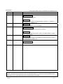
REVISIONS
* The manual number is given on the bottom left of the back cover.
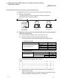
Print Date
Jun., 2001
Apr., 2003
* Manual Number
SH (NA)-080180-A First Edition
SH (NA)-080180-B
Model Addition
QJ71E71-B5, QJ71E71-B2
Revision
Correction
About the Generic Terms and Abbreviations, Section 1.1, Section 2.1,
2.2, Section 4.1, Chapter 6 (1)
Aug., 2005
SH (NA)-080180-C
Jun., 2007
SH (NA)-080180-D
Correction
Section 1.1, Section 4.1, 4.4.3, Chapter 6
Change of a term
"PLC" was changed to "programmable controller".
Correction
About Manuals, About the Generic Terms and Abbreviations, Section
3.2 (1), Chapter 6 (3)
Oct., 2008
SH (NA)-080180-E
Feb., 2013
SH (NA)-080180-F Revision on the addition of the LJ71E71-100
Correction
SAFETY PRECAUTIONS, About Manuals, About the Generic Terms
and Abbreviations, Section 4.4
Model Addition
LJ71E71-100
Japanese Manual Version SH-080144-F
This manual confers no industrial property rights or any rights of any other kind, nor does it confer any patent
licenses. Mitsubishi Electric Corporation cannot be held responsible for any problems involving industrial property
rights which may occur as a result of using the contents noted in this manual.
2001 MITSUBISHI ELECTRIC CORPORATION
A-4
A-4
INTRODUCTION
Thank you for purchasing the Mitsubishi MELSEC-Q or -L series programmable controllers.
This manual describes how to use the Web functions with the Ethernet interface module.
Before using this product, please read this manual and the relevant manuals carefully and develop familiarity
with the functions and performance of the MELSEC-Q or -L series programmable controller to handle the
product correctly.
When applying the program examples introduced in this manual to the actual system, ensure the applicability
and confirm that it will not cause system control problems.
Please make sure that the end users read this manual.
REMARK
Unless otherwise specified, this manual describes the program examples in which
the I/O numbers of X/Y00 to X/Y1F are assigned for the Ethernet interface module.
For I/O number assignment, refer to the user's manual (Function Explanation,
Program Fundamentals) for the CPU module used.
CONTENTS (This manual)
SAFETY PRECAUTIONS..............................................................................................................................ACONDITIONS OF USE FOR THE PRODUCT .............................................................................................AREVISIONS ....................................................................................................................................................ACONTENTS....................................................................................................................................................ARELEVANT MANUALS .................................................................................................................................AThe Manual's Use ..........................................................................................................................................ATERMS ...........................................................................................................................................................A-
1
3
4
5
7
8
9
1 OVERVIEW
1- 1 to 1- 4
2 SYSTEM CONFIGURATIONS
2- 1 to 2- 4
2.1 System Configurations............................................................................................................................ 2- 1
2.2 Precautions for Using the Web Function................................................................................................ 2- 3
3 OPERATING PROCEDURE
3- 1 to 3- 4
3.1 General Procedure up to Communication Using the Web Function ..................................................... 3- 1
3.2 How to Obtain and Set Up the Communication Library and the Sample Screen................................. 3- 2
4 VERIFYING THE OPERATION OF THE WEB FUNCTION USING A SAMPLE SCREEN
4- 1 to 4-17
4.1 Web Function Items Available on the Sample Screen .......................................................................... 4- 1
4.2 Operating Procedure............................................................................................................................... 4- 1
4.3 Explanation of the Sample Screen ......................................................................................................... 4- 2
4.4 Example of Data Communication on the Sample Screen ..................................................................... 4- 3
4.4.1 Device Read/Write ........................................................................................................................... 4- 5
4.4.2 Remote RUN/STOP......................................................................................................................... 4- 9
4.4.3 Data Request.................................................................................................................................... 4-11
4.4.4 Proxy Setting .................................................................................................................................... 4-14
4.5 Configurations of Files on the Sample Screen....................................................................................... 4-16
A-5
A-5
5 EXAMPLE OF CREATING A FILE FOR ACCESSING THE PROGRAMMABLE CONTROLLER
5- 1 to 5- 9
6 COMMUNICATION LIBRARY FUNCTIONS
INDEX
A-6
6- 1 to 6- 5
Index- 1 to Index- 2
A-6
RELEVANT MANUALS
The manuals related to this product are listed below.
Order each manual as needed, referring to the following lists.
Manual number
(Model code)
Manual name
Q Corresponding Ethernet Interface Module User's Manual (Basic)
Specifications, procedures for data communication with external devices, line
connection (open/close), fixed buffer communication, random access buffer
communication, and troubleshooting of the Ethernet interface module
SH-080009
(13JL88)
(sold separately)
MELSEC-L Ethernet Interface Module User's Manual (Basic)
Specifications, procedures for data communication with external devices, line
connection (open/close), fixed buffer communication, random access buffer
communication, and troubleshooting of the Ethernet interface module
SH081105ENG
(13JZ73)
(sold separately)
MELSEC-Q/L Ethernet Interface Module User's Manual (Application)
E-mail function, communication via MELSECNET/H or MELSECNET/10,
communication using the data link instructions, and file transfer function (FTP server)
of the Ethernet interface module
SH-080010
(13JL89)
(sold separately)
MELSEC-Q/L MELSEC Communication Protocol Reference Manual
Details of MELSEC communication protocol (MC protocol) that is used for data
(sold separately)
communication between a target device and a CPU module
A-7
SH-080008
(13JF89)
A-7
The Manual's Use
How to use this manual
Please refer to the applicable items of this manual by referring to the following
outline of the contents of this manual:
(1) To find out how to use the Web function and to learn about the
operating environment
Chapter 1 describes an overview of the Web function.
Chapter 2 describes a system configuration for utilizing the Web function.
(2) To find out about the procedure for using the Web function
Section 3.1 describes the procedure up to communication using the Web
function.
Section 3.2 describes how to obtain and set up the communication library and
sample screen.
Section 4.2 describes the procedure for accessing the programmable
controller using a sample screen.
(3) To check the operation of the Web function
Chapter 4 describes an example when accessing the programmable controller
using a sample screen.
(4) To create data used to access the programmable controller by the
user
Section 4.5 describes an overview of ASP (Active Server Pages) files for
accessing the programmable controller, as well as HTML (Hyper Text Markup
Language) files to be displayed by the Web browser, both of which are to be
created by the user.
Chapter 5 describes an example of file creation for programmable controller
access.
Chapter 6 describes the communication library functions.
A-8
A-8
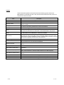
TERMS
Unless otherwise specified, this manual uses the following generic terms and
abbreviations to describe QJ71E71-100, QJ71E71-B5 and QJ71E71-B2, and LJ71100 Ethernet Interface Modules.
Term
Description
ASP
Abbreviation for Active Server Pages
CPU module
A generic term for QCPU and LCPU
Ethernet module
The abbreviation for Model QJ71E71-100, QJ71E71-B5 and QJ71E71-B2 Ethernet
interface modules
External device
Generic term for personal computers, computers, workstations and Ethernet module
etc. that are connected by the Ethernet for data communication
HTML
Abbreviation for Hyper Text Markup Language.
HTTP
Abbreviation for Hyper Text Transfer Protocol
This protocol sends/receives the information on World Wide Web in the Internet.
LCPU
The abbreviation for the MELSEC-L series CPU module
MC protocol
Abbreviation for MELSEC communication Protocol
This protocol is used to access MC protocol supporting modules, such as the serial
communication module and Ethernet module, or programmable controllers connected
to MC protocol supporting modules from external devices.
Programming tool
A generic term for GX Works2 and GX Developer
QCPU
A generic term for the Basic model QCPU, High Performance model QCPU, Process
CPU, Redundant CPU, and Universal model QCPU
Reference Manual
The abbreviation for the MELSEC-Q/L MELSEC Communication Protocol Reference
Manual
URL
Abbreviation for Uniform Resource Locator.
User's Manual (Application)
The abbreviation for the MELSEC-Q/L Ethernet Interface Module User's Manual
(Application)
User's Manual (Basic)
The abbreviation for the Q Corresponding Ethernet Interface Module Use's Manual
(Basic) and the MELSEC-L Ethernet Interface Module User's Manual (Basic)
User's Manual (Web function)
The abbreviation for the MELSEC-Q/L Ethernet Interface Module Use's Manual (Web
function)
Web browsers
Abbreviation for software that views Web pages.
Web server
Abbreviation for the computer in which Web server software operates.
Web server software
Generic name of server software that supports the WWW (World Wide Web) services.
A-9
A-9
1 OVERVIEW
MELSEC-Q/L
1 OVERVIEW
1
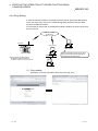
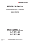
The following shows an overview of the Web function with the Ethernet module.
(1) Programmable controller monitoring via the Internet using the Web
function
The Web function with the Ethernet module is used for the system administrator
to monitor the MELSEC-Q/L series CPU modules at a remote location via the
Internet, using a Web browser.
Internet network
(Public line)
Internet
service provider
Internet
service provider
Router
Web server
Ethernet module
External devices (Web browsers)
1-1
1-1
1 OVERVIEW
MELSEC-Q/L
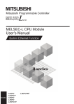
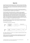
(2) Access function to the programmable controller
By using the Web function, the programmable controller data can be collected or
updated, the CPU module operation can be monitored, and the status control of
the CPU module can be performed in order to control and monitor the equipment
on the programmable controller side using a Web browser ( 1).
1 With the Web function, exchange of information between the Ethernet
module and the Web server, and between the Web server and the Web
browser is performed via HTTP.
With the Web function, the programmable controller is accessed by
sending/receiving messages of the MC protocol, which are used for
communication between the programmable controller and the external
device, via HTTP.
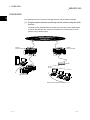
(3) Availability of a communication library and a sample screen
(a)
The Web function can be used by installing the following:
Required device/software
Programmable controller side
Server computer
(Web server)
Device on the Web browser side
(b)
Description
Ethernet module
Subject module of this manual
Web server
Refer to Section 2.1 (4).
Communication library
Refer to item (b).
ASP files
Files created by the user to be used
for accessing the programmable
controller
HTML files
Files created by the user to be used
for displaying the Web browser
Web browser
Refer to Section 2.1 (4).
A sample screen (HTML files, ASP files) is provided. It is used to check the
access function to the programmable controller using the communication
library and the Web function. Contact your local agency or marketing
company.
1) The user can easily create ASP files in order to access the
programmable controller by using the communication library.
In addition, the result of access to the programmable controller using
ASP files can arbitrarily be displayed on the Web browser using usercreated HTML files.
External device
Web server
Ethernet module
HTTP
header
MC protocol
(Command message)
MC protocol
(Response message)
HTTP
HTTP
header
Web browser
HTML
ASP
Execution
of the ASP file
Display of
requests/results
Communication
library
1-2
1-2
1
1 OVERVIEW
MELSEC-Q/L
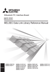
2)
Device memory read/write, remote RUN/STOP and other operations
can be performed for the Q/LCPU of an Ethernet module mounted
station by specifying the URL of the sample screen using the Web
browser.
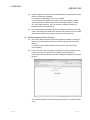
The execution result is displayed by simply entering the access
device, the number of devices, etc. in the items to be displayed in
the Web browser.
(Example) To read four points of data registers D0 = 1234H,
D1 = 5678H, D2 = 9ABCH, and D3 = 1234H.
(Input screen)
(Execution result screen)
(4) Utilizing the Web server
Access to the programmable controller using the Web function becomes possible
by combining an Ethernet module and a Web server computer.
(a) A system can easily be configured by utilizing a Web server.
1) Complicated screens can be created.
The user can create multiple HTML files and HTML files of large sizes
without being limited by the size of the Ethernet module memory by
storing these HTML files in a Web server.
The HTML files for Web browser can be created or changed easily if
the user has knowledge of creating a web page.
1-3
2)
Reducing the load on the Ethernet module
Since access programs for the programmable controller and control
programs for Web browsers are executed in the Web server, the load
on the Ethernet module can be minimized when accessing the
programmable controller.
3)
Separating an Ethernet line
By separating the line connecting between the Ethernet module and
the Web server, and the line between the Web server and the Web
browser, the screen data for the Web browser will not be sent to the
line connecting between the Ethernet module and the Web server.
Therefore, it is possible to reduce effect on the transmission/reception
of data for system control for communication between the Ethernet
module and the external device.
1-3
1 OVERVIEW
MELSEC-Q/L
(b)
System expansion can easily be achieved because the Web server and the
Ethernet module are separated.
For example, the following function can be added:
If it is necessary to maintain the security of the programmable controller
system against any unauthorized access (to damage programs or data,
etc.) from external devices, the user can take a measure by adding a
firewall function to the Web server.
(c)
The communication information between the Ethernet module and the Web
server, and between the Web server and the Web browser can be recorded
and used for maintenance using the functions of the Web server.
(5) Remote password check function
(a)
The remote password check function of the Ethernet module is provided to
prevent any unauthorized access to the Q/LCPU by the user at a remote
location.
For details on the remote password check function, refer to the user's
manual (Basic).
(b)
If the HTTP port is set as the target connection for remote password check,
access to the Q/LCPU will become possible by performing unlock
processing of the remote password via the dialog box displayed in the Web
browser.
The remote password lock processing is performed when the Web browser
ends.
1-4
1-4
2 SYSTEM CONFIGURATIONS
MELSEC-Q/L
2 SYSTEM CONFIGURATIONS
2.1 System Configurations
This section explains the environment and system configurations for using the Web
function.
The following describes the system configurations for using the Web function of the
Ethernet module.
2
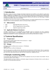
(1) System configuration when accessing via the Internet
Internet network
(public line)
Internet
service provider
Internet
service provider
<System administrator>
Web server (see (4))
Files
Communication library (DLL)
Sample screen (HTML, ASP)
Router
Ethernet
Provided by
Mitsubishi Electric Corporation
Firewall
Files
Commercially sold product
Web browser (see (4))
HTML files for Web browser
ASP files for programmable
controller access
Created by the user
<Factory/production site>
Commercially sold product
External device
Router
Ethernet
Ethernet module (see (3))
(2) System configuration when accessing via the Intranet
Ethernet
Ethernet module (see (3))
Web server (see (4))
Files
Communication library (DLL)
Sample screen (HTML, ASP)
Web browser (see (4))
Provided by
Mitsubishi Electric Corporation
Files
Commercially sold product
2-1
HTML files for Web browser
ASP files for programmable
controller access
Commercially sold product
Created by the user
External device
2-1
2 SYSTEM CONFIGURATIONS
MELSEC-Q/L
(3) Ethernet module
The Ethernet module that can use the Web function is as follows:
• Model QJ71E71-100 Ethernet interface module
• Model QJ71E71-B5 Ethernet interface module
• Model QJ71E71-B2 Ethernet interface module
• Model LJ71E71-100 Ethernet interface module
For the applicable systems and the devices required for network configuration of
the above Ethernet module, refer to the user's manual (Basic).
(4) Web server and Web browser
The operating environment of the Web server is listed below.
Item
Operating environment
Internet Information Services 5.1 by Microsoft® Corporation
Web Server
Internet Information Services 7.5 by Microsoft® Corporation
Internet Information Services 8.0 by Microsoft® Corporation
Web browser
Internet Explorer 8.0 or later version by Microsoft® Corporation
(a) The following files need to set up in the Web server to use the Web function.
• Communication library
• HTML files for Web browser
• ASP files for programmable controller access
2-2
2-2
2
2 SYSTEM CONFIGURATIONS
MELSEC-Q/L
2.2 Precautions for Using the Web Function
(1)
Precautions for configuring a system
(a)
It is necessary to take sufficient security measures for connection to the
Internet.
Consult with a network installer, an Internet service provider, and a network
administrator (person in charge of network planning and IP address
management).
Mitsubishi Electric Corporation will not take any responsibility for any
system problems that may occur while connecting to the Internet.
(b)
If a firewall function is installed in the network, set it so that the HTTP
protocol can pass the firewall function.
(c)
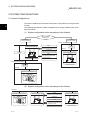
When accessing multiple Ethernet modules via one Web server, the next
process may not be executed during the time from the request start through
until the response is returned.
If no response is received due to a communication line fault, the next
processing may be delayed until a timeout occurs on the Web server.
(Example) Accessing 2 Ethernet modules using one Web server
Ethernet module 1)
Because no response is received
from Ethernet module 1), the next
request cannot be handled.
Web browser 1)
Web server
Response to
Web server
Line fault
Internet
Web browser 2)
Intranet
Ethernet module 2)
• Access from Web browser 1) to Ethernet module 1)
• Access from Web browser 2) to Ethernet module 2)
The line fault between the Web server and Ethernet module 1) disables the
response from Ethernet module 1) to the Web server. This brings the Web
server into the wait status and the access request from Web browser 2) to
Ethernet module 2) has to wait at the Web server.
2-3
2-3
2 SYSTEM CONFIGURATIONS
MELSEC-Q/L
(2) Precautions relating to security
The remote password check function is not designed to completely prevent
unauthorized access. When accessing a CPU module via the Internet, and if it is
necessary to maintain the security of the programmable controller system, the
user should take appropriate measures.
Mitsubishi Electric Corporation will not take any responsibility for any system
problems that may occur due to unauthorized access.
Examples of measures against unauthorized access
• Installing a firewall function
• Security measures by the Web server
Take necessary measures by referring to the User's Manual of the device
used.
(3) Precautions for accessing the CPU module
2-4
(a)
When the user creates an ASP or HTML file for the Web function, use the
communication library (QeAccess.dll) provided by Mitsubishi Electric
Corporation.
The communication library cannot be created by the user.
For details on the communication library functions, refer to Chapter 6.
(b)
The Web server provides a log function that records file access, etc.
Periodically collect the access log for the programmable controller access
file, and check the access status.
If there are too many unauthorized access logs to the Web server, the user
should take appropriate measures to resolve unauthorized access.
(c)
A maximum of four connections are allowed as the simultaneous access
count when accessing the Ethernet module using the Web function.
If this maximum allowable access number is exceeded, a timeout error will
be returned from a communication library function.
In case a timeout error occurs, extend the access interval time and retry.
2-4
3 OPERATING PROCEDURE
MELSEC-Q/L
3 OPERATING PROCEDURE
3.1 General Procedure up to Communication Using the Web Function
The following shows a general procedure up to access to the programmable controller
from the Web server using the Web function.
(1) Settings on the Ethernet module side
Start the Ethernet module mounted station.
(When it is operating normally, the [INIT. ] LED on the front of the Ethernet
module lights up.)
For details, refer to the User's Manual (Basic).
3
(2) Settings on the external device side (Web server, Web browser)
3-1
3-1
3 OPERATING PROCEDURE
MELSEC-Q/L
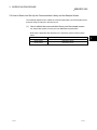
3.2 How to Obtain and Set Up the Communication Library and the Sample Screen
The following explains how to obtain the communication library and the sample screen,
and their setup procedures in the Web server.
(1) How to obtain the communication library and the sample screen
For sample files, please consult your local Mitsubishi representative.
Note that the applicable files depend on the operation system used as shown
below.
3-2
OS
Sample file for the Web function
32-bit version
qeaccess-e-32.zip
64-bit version
qeaccess-e-64.zip
3
3-2
3 OPERATING PROCEDURE
MELSEC-Q/L
(2) Setup
Set up the qeacess.exe file in the Web server.
POINT
Web server software must be installed in the Web server in advance. For the
operating environment, refer to Section 2.1.
(Procedure 1) Decompressing the downloaded file
Move the compressed qeaccess-e.exe file to any folder and
decompress it. The following shows the file structure after
decompression.
The decompressed folder (_qj71e71) can be opened in the both
Q and L series.
File name
dev_read.html
dev_write.html
foot.html
index.html
menu.html
proxy_set.html
req_cmd.html
rmt_run.html
rmt_stop.html
Folder name
_qj71e71
_asp
_dll
_img
dev_read.asp
dev_write.asp
proxy_set.asp
req_cmd.asp
rmt_run.asp
rmt_stop.asp
QeAccess.dll
mitsubishi.gif
qeaccess_logo.gif
Remark
For sample screen
• HTML files
For sample screen
• ASP files
Communication library
• DLL file
For sample screen
• Image files
(Procedure 2) Copying the files
Copy the decompressed folder (_qj71e71) under the root folder
“\Inetpub\wwwroot” of the Web server.
3-3
3-3
3 OPERATING PROCEDURE
MELSEC-Q/L
(Procedure 3) Registering the communication library (DLL file)
Register the DLL file in the OS registry of the Web server. The
following shows how to register the file using a command prompt.
1)
Open a command prompt of the Web server.
2)
Switch the current directory.
C:\> cd\Inetpub\wwwroot\_qj71e71\_dll
3)
Input the directory path of the regsvr32 command for Windows.
set path = C:\windows\system32
4)
Register the communication library DLL with the regsvr32 command for
Windows.
C:\> \Inetpub\wwwroot\_qj71e71\_dll> regsvr32 qeaccess.dll
(Example) When the root directory is in drive C
(Procedure 4) When all settings are complete, restart the Web server.
REMARKS
When deleting the files that have been set up, delete all files below the _qj71e71
folder of the root folder “\Inetpub\wwwroot.”
3-4
3-4
4 VERIFYING THE OPERATION OF THE WEB FUNCTION USING
A SAMPLE SCREEN
MELSEC-Q/L
4 VERIFYING THE OPERATION OF THE WEB FUNCTION USING
A SAMPLE SCREEN
This chapter explains how to access a CPU module using the Web function through a
sample screen.
4.1 Web Function Items Available on the Sample Screen
The following lists the items of the Web function whose operations can be verified on
the sample screen.
Function
4
File name
Device Read
dev_read.html
Device Write
dev_write.html
Description
Reads from a bit devices (such as X, Y, or M) in 16-point units.
Reads from a word devices (such as D, R, T, or C) in one-point units.
Writes to a bit devices (such as X, Y, or M) in 16-point units.
Writes to a word devices (such as D, R, T, or C) in one-point units.
Remote RUN
rmt_run.html
Requests a remote RUN operation to the CPU module.
Remote STOP
rmt_stop.html
Requests a remote STOP operation to the CPU module.
Data Request
req_cmd.html
Sends one MC protocol application data (subheader + text) that was input.
Proxy Setting
proxy_set.html
Specifies the proxy server when an Ethernet module is connected via a proxy server.
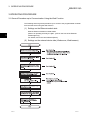
4.2 Operating Procedure
The following shows the operating procedure for accessing a CPU module from a
sample screen.
Set up both the sample screen and the communication library in the Web server in
advance. (Refer to Chapter 3.)
Start
Start the Web browser and specify
the URL for the sample screen.
See Section 4.3.
The Device Read screen (Index screen) is displayed.
Select the function item to be used
from the menu.
See Section 4.3.
Device
Read
Device
Write
Remote
RUN
Remote
STOP
Data
Request
Execution
result
Execution
result
Execution
result
Execution
result
Execution
result
Close the Web browser.
Proxy
Setting ( 1)
Execution
result
See Section 4.4.
Enter the required items
on the screen displayed.
See Section 4.4.
The execution result is
displayed.
1 Set this to access an Ethernet module
via the proxy server.
End
4-1
4-1
4 VERIFYING THE OPERATION OF THE WEB FUNCTION USING
A SAMPLE SCREEN
MELSEC-Q/L
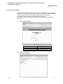
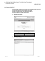
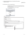
4.3 Explanation of the Sample Screen
The following shows the operations that are performed on the sample screen.
(1) Setting screen
1) Start the Web browser and specify
the URL for the sample screen.
(Example) If the host name of the Web server
is qe_serv, specify
http://qe_serv/_qj71e71/index.html.
2) Select the Web function item to be
used from the menu.
3) Enter the required items on each function
screen and execute the selected Web
function item.
(Example) The screen display when
Device Read has been selected.
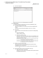
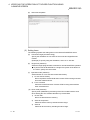
(2) Execution result screen
1) The execution result is displayed
on a new screen.
(When completed normally)
The execution result is displayed.
(When completed abnormally)
An error code is displayed.
Refer to the explanation of
troubleshooting in the User's
Manual (Basic).
4-2
4-2
4
4 VERIFYING THE OPERATION OF THE WEB FUNCTION USING
A SAMPLE SCREEN
MELSEC-Q/L
4.4 Example of Data Communication on the Sample Screen
The following shows how to access a CPU module using the sample screen.
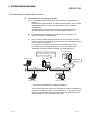
(1) System configuration
The following shows a system configuration for data communication.
(Explanation of proxy setting is omitted.)
Network No.1
QJ71E71-100
[10.97.85.200]
Station number: 1
Web server
[10.97.85.10]
Web browser
[10.97.85.201]
(2) Execution environment for the above data communication example
(Ethernet module side)
(a)
Mount an Ethernet module to slot 0 of the basic base unit.
(b)
Set the parameters for Ethernet using a programming tool.
For the setting items other than shown below, use the default values.
1)
Network parameters
Setting screen
Setting item
Network type
Network parameters setting the number of
Ethernet/CC IE/MELSECNET cards
Operational settings
2)
Setting data
Ethernet
Starting I/O No.
0000
Network No.
1
Group No.
1
Station No.
1
IP address
[10. 97. 85. 200]
Remote password
Setting screen
Setting item
Setting data
Password setting
Remote password settings
Remote password detail settings
4-3
Password active module settings
System connection
Model name
Start X/Y
QJ71E71
0000
Check “HTTP port.”
(c)
Write data to the data registers D0 through D3.
(d)
Write the Ethernet parameters and programs to the CPU module, and
restart the CPU module.
When it is operating normally, the initial processing of the Ethernet module
will be completed normally and the [INIT. ] LED will be lit.
4-3
4 VERIFYING THE OPERATION OF THE WEB FUNCTION USING
A SAMPLE SCREEN
MELSEC-Q/L
(3) Execution environment of the above data communication example
(external device side)
(a)
Web server
1) Set up the communication library and the sample screen. (Refer to
Section 3.2 (2).)
2) Register the DLL file in the OS registry. (Refer to Section 3.2 (2).)
This registration is not required if it has already been registered.
3) After all settings are completed, restart the Web server.
(b)
Web browser
Start the Web browser.
(4) Execution of data communication
4-4
(a)
URL display on the sample screen
Specify the following URL for the sample screen in the Web browser.
http://10.97.85.10/_qj71e71/index.html
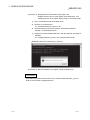
(b)
Unlocking the remote password
If the port of the Ethernet module using for data communication with the
Web server is subject to remote password check, the following dialog box
will be displayed when access to a CPU module will start.
Enter the remote password to perform unlock processing.
This operation is not required if the port of the Ethernet module is not
subject to remote password check. (Therefore, the following dialog box
will not be displayed.)
(c)
Data communication
For an example of data communication, refer to Section 4.4.1 and
subsequent sections.
(d)
End of data communication
Close the Web browser.
4-4
4 VERIFYING THE OPERATION OF THE WEB FUNCTION USING
A SAMPLE SCREEN
MELSEC-Q/L
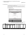
4.4.1 Device Read/Write
The Device Read and Device Write functions (QnA compatible 3E frame commands
0401 and 1401) read and write the bit device memory (16-bit units) and word device
memory (1-word units) of the local station's CPU module in batch mode.
For details on the MC protocol, refer to the Reference Manual.
This section explains an example of reading four points of the data registers D0
through D3.
(1) Device Read Screen
Setting item
Connection target
Start device
Number of device
Setting value
10. 97. 85. 200
D0
4
(2) Execution result
(a)
4-5
Normal completion
4-5
4 VERIFYING THE OPERATION OF THE WEB FUNCTION USING
A SAMPLE SCREEN
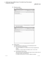
(b)
MELSEC-Q/L
Abnormal completion
(3) Setting items
The following explains the setting items on the Device Read/Write screen.
(a) Connection target (character string)
Specify the IP address or host name of the connection target Ethernet
module.
(Example) To specify using the IP address, enter 10. 97. 85. 200.
(b)
Start device
Specify the device code and start device of the device for reading/writing
data.
1) Device code (selection)
Select the device memory.
2)
4-6
Start device (character string)
Specify the start number of the device memory for which data is to be
read/written. Specify the start device number in decimal/hexadecimal
from the target device memory.
(Example) To specify the data register D100, select the device code
"D" and specify "100" for the start device.
(Example) To specify the link register W1FF, select the device code
"W" and specify "1FF" for the start device.
(c)
Number of device (character string)
Specify the number of points (hexadecimal) of the device for which
reading/writing are to be performed.
(Example) To specify 20 points as the number of device points, specify
"14".
(d)
Read data/write data (character string) (Refer to item (4).)
1) Read data (execution result screen)
Displays the content of data for the number of device points read from
the specified device memory.
4-6
4 VERIFYING THE OPERATION OF THE WEB FUNCTION USING
A SAMPLE SCREEN
2)
MELSEC-Q/L
Write data
Specify the data to be written to the device for the number of device
points.
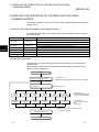
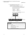
(4) Arrangement of read/write data
The following explains the transmission method and placement of the bit device
data and word device data handled by device read/write operation.
The data is handled in word units during device read/write operation on the
sample screen.
(a)
When reading/writing the bit device memory
In the bit device memory, one word is expressed in 4-bit units sequentially
from upper bits in hexadecimal.
(Example) To write data to 32 points from the internal relay M16
(In the case of data read operation, the content of data
(ON/OFF status) when 32 points are specified from the internal
relay M16 is shown.)
Specify each setting item as follows:
• Device code
: Select "M".
• Start device
: Specify "16".
• Number of device : Specify "2".
• Write data
: Specify "AB1234CD".
The following data will be written. (In the case of device read operation, the
following data will be read.)
Data
A
A
B
1
B
1
2
Data
2
3
4
3
C
D
4
C
D
B15 B14 B13 B12 B11B10 B9 B8 B7 B6 B5 B4 B3 B2 B1 B0 B15 B14 B13 B12 B11B10 B9 B8 B7 B6 B5 B4 B3 B2 B1 B0
1 0 1 0 1 0 1 1 0 0 0 1 0 0 1 0 0 0 1 1 0 1 0 0 1 1 0 0 1 1 0 1
1: Indicates ON.
0: Indicates OFF.
M M M M M M M M M M M M M M M M M M M M M M M M M M M M M M M M
31 30 29 28 27 26 25 24 23 22 21 20 19 18 17 16 47 46 45 44 43 42 41 40 39 38 37 36 35 34 33 32
4-7
4-7
4 VERIFYING THE OPERATION OF THE WEB FUNCTION USING
A SAMPLE SCREEN
(b)
MELSEC-Q/L
When reading/writing the word device memory
In the word device memory, one word is expressed in 4-bit units
sequentially from upper bits in hexadecimal.
(Example) To write data to the data registers D350 and D351
(In the case of data read operation, the content of data when
the data registers D350 and D351 are specified is shown.)
Specify each setting item as follows:
• Device code
: Select "D".
• Start device
: Specify "350".
• Number of device : Specify "2".
• Write data
: Specify "56AB170F".
The following data will be written. (In the case of device read
operation, the following data will be read.)
Data
5
5
6
A
6
A
B
Data
B
1
7
1
0
F
7
0
F
B15 B14 B13 B12 B11B10 B9 B8 B7 B6 B5 B4 B3 B2 B1 B0 B15 B14 B13 B12 B11B10 B9 B8 B7 B6 B5 B4 B3 B2 B1 B0
0 1 0 1 0 1 1 0 1 0 1 0 1 0 1 1 0 0 0 1 0 1 1 1 0 0 0 0 1 1 1 1
The content of D350 indicates 56ABH
(22187 in decimal).
1: Indicates ON.
0: Indicates OFF.
The content of D351 indicates 170FH
(5903 in decimal).
POINT
If values (real numbers, character strings) other than integers are stored in the word
device memory from which data is to be read, the Ethernet module reads the stored
values as integer values.
(Example 1) If a real number (0.75) is stored in D0 and D1, it will be read as the
following integer value:
“00003F40” (D0 = 0000H, D1 = 3F40H)
(Example 2) If a character string (“12AB”) is stored in D2 and D3, it will be read as
the following integer value:
“32314241” (D2 = 3231H, D3 = 4241H)
4-8
4-8
4 VERIFYING THE OPERATION OF THE WEB FUNCTION USING
A SAMPLE SCREEN
MELSEC-Q/L
4.4.2 Remote RUN/STOP
The Remote RUN and Remote STOP functions (QnA compatible 3E frame commands
1001 and 1002) stop and run the local station's CPU module.
For details on the MC protocol, refer to the Reference Manual.
This section explains an example of Remote RUN.
(1) Remote RUN screen
Setting item
Connection target
Operation mode
Clear mode
Setting value
10. 97. 85. 200
Do not execute forcibly
Do not clear.
(2) Execution result
(a)
4-9
Normal completion
4-9
4 VERIFYING THE OPERATION OF THE WEB FUNCTION USING
A SAMPLE SCREEN
(b)
MELSEC-Q/L
Abnormal completion
(3) Setting items
The following explains the setting items on the Remote RUN/STOP screen.
(a) Connection target (character string)
Specify the IP address or host name of the connection target Ethernet
module.
(Example) To specify using the IP address, enter 10. 97. 85. 200.
(b)
Target PLC (selection)
Select the target programmable controller for remote RUN/STOP operation.
To perform remote RUN/STOP to a single CPU system of the QCPU or
the LCPU, specify the control CPU.
(c)
Operation mode (selection)
Select whether or not to execute remote RUN forcibly.
1) Do not execute forcibly
Does not perform remote RUN when remote STOP is being executed
from other external device.
2)
Force execution
Performs remote RUN even if remote STOP is being executed from
other external device.
(d) Clear mode (selection)
Specify clear (initialization) processing of the CPU module's device clear
when starting the CPU module calculation by remote RUN.
1) Do not clear
Does not clear the device memory.
4 - 10
2)
Clear all except latch
Clears the device memory outside the latch range.
3)
Clear all
Clears all device memory including the latch range.
4 - 10
4 VERIFYING THE OPERATION OF THE WEB FUNCTION USING
A SAMPLE SCREEN
MELSEC-Q/L
4.4.3 Data Request
The Data Request function accesses the CPU module by inputting the application data
of the MC protocol (QnA compatible 3E frame).
This section explains how to read four points of the data registers D0 through D3 by
specifying the application data of Device Memory Batch Read (command 0401) for the
QnA compatible 3E frame.
(1) Data Request screen
Setting item
Setting value
Connection target
10. 97. 85. 200
Command Data
500000FF03FF000018001004010000D
0000000004
(Example) The following shows an example of the format for the application data
of the MC protocol that is equivalent to the command data.
Text (Command)
Q header
5
0
0
Request
destination
module
I/O No.
Network
PC No.
No.
Subheader
0
Request
destination
module
station
No.
CPU
monitoring
timer
Request data
length
Command
Subcommand
H
L
H
L
H
-
-
L
H
L
H
-
-
L
H
-
-
L
H
-
-
L
H
-
-
L
0
0
F
F
0
3
F
F
0
0
0
0
1
8
0
0
1
0
0
4
0
1
0
0
0
0
Device
code
D
Number of
device
Head device
H
-
-
-
-
L
H
-
-
L
0
0
0
0
0
0
0
0
0
4
35H 30H 30H 30H 30H 30H 46H 46H 30H 33H 46H 46H 30H 30H 30H 30H 31H 38H 30H 30H 31H 30H 30H 34H 30H 31H 30H 30H 30H 30H 44H 2AH 30H 30H 30H 30H 30H 30H 30H 30H 30H 34H
Specify this part in the command data.
4 - 11
4 - 11
4 VERIFYING THE OPERATION OF THE WEB FUNCTION USING
A SAMPLE SCREEN
MELSEC-Q/L
(2) Execution result
(a)
Normal completion
(b)
Abnormal completion
(3) Setting items
The following explains the setting items on the Data Request screen.
(a) Connection target (character string)
Specify the IP address or host name of the connection target Ethernet
module.
(Example) To specify using the IP address, enter 10. 97. 85. 200.
(b) Command data (character string)
Specify the MC protocol application data using the same character string as
the setting for ASCII code transmission.
For details on the MC protocol, refer to the Reference Manual.
4 - 12
4 - 12
4 VERIFYING THE OPERATION OF THE WEB FUNCTION USING
A SAMPLE SCREEN
MELSEC-Q/L
(4) Precautions for use of Data Request
(a) Available communication frame
Application data of the QnA compatible 3E frame command can be
specified.
Specification of the 4E or A compatible 1E frame is not allowed.
(b) No. of commands that can be specified at a time
Only one command can be specified at a time.
Continuous specification of more than one command is not allowed.
(c) Remote password unlock/lock (Command: 1630/1631)
Remote password unlock/lock (Command: 1630/1631) is not available.
The remote password to the HTTP port is unlocked in the dialog box, which
is displayed in the Web browser when accessing to a CPU module. (Refer
to Section 1(5).)
4 - 13
4 - 13
4 VERIFYING THE OPERATION OF THE WEB FUNCTION USING
A SAMPLE SCREEN
MELSEC-Q/L
4.4.4 Proxy Setting
In case an Ethernet module is connected via a proxy server, specify the address and
HTTP port of the proxy server to be routed through when accessing from the Web
server to the Ethernet module.
It is necessary to set the URL of the Ethernet module in advance in order to access via
the proxy server.
Internet network
(Public line)
Ethernet
Proxy server
Ethernet module
It is necessary to set the URL of
the Ethernet module in advance
in order to access via the proxy server.
Ethernet
External device
Web browser
Specify the address and HTTP port of the
proxy server to be routed through when
accessing from the Web server.
Web server
(1) Proxy setting
(Example) To set the port 8000 of the proxy server (qe_serv)
4 - 14
4 - 14
4 VERIFYING THE OPERATION OF THE WEB FUNCTION USING
A SAMPLE SCREEN
MELSEC-Q/L
(2) Resetting proxy
(3) Setting items
The following explains the setting items on the Proxy Setting screen.
For the IP address and port of the proxy server to be used, consult with the
network administrator (the person in charge of network planning and IP address
management), and then specify them.
(a) Proxy (character string)
Specify the IP address or host name of the proxy server to be routed
through.
(Example) To specify using the IP address, enter 10. 97. 85. 1
(b) Port (character string)
Specify the port to be used.
4 - 15
4 - 15
4 VERIFYING THE OPERATION OF THE WEB FUNCTION USING
A SAMPLE SCREEN
MELSEC-Q/L
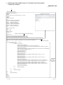
4.5 Configurations of Files on the Sample Screen
The following shows the configuration of the HTML files for Web browser and the
configuration of the ASP files for accessing the programmable controller, using the
Device Read sample screen.
For communication library functions, refer to Chapter 6.
(Device Read screen)
HTML file (dev_read.html)
<HTML>
<TITLE>
- Device Read - QE-ACCESS version 1.1
</TITLE>
<BODY BGCOLOR="#FFFFFF"><BR>
<CENTER>
<IMG SRC=_img/qeaccess_logo.gif><BR>
<TT><FONT SIZE=5 FACE="Arial,Lucida,Sans,Time Roman">- Device Read -</FONT></TT><BR>
<!Action>
(Specify the
<FORM ACTION="_asp/dev_read.asp" METHOD="POST" TARGET="_BLINK"><BR> transmission
<TABLE BORDER="0">
destination)
<!Connection target>
<TR>
<TD WIDTH="140" ALIGN="RIGHT"><FONT FACE="Arial,Lucida,Sans,Time Roman">Connection target</FONT></TD>
<TD WIDTH="200" COLSPAN="2"><INPUT TYPE="TEXT" SIZE="26" NAME="iHostName"></TD>
</TR>
.
.
<!Input type>
(Execute an ASP file)
<INPUT TYPE="SUBMIT" VALUE="Read">
<INPUT TYPE="RESET" VALUE="Clear">
</CENTER>
</BODY>
</HTML>
1)
4 - 16
4 - 16
4 VERIFYING THE OPERATION OF THE WEB FUNCTION USING
A SAMPLE SCREEN
MELSEC-Q/L
1)
ASP file (dev_read.asp)
<%@ LANGUAGE="VBScript" %>
<HTML>
<HEAD>
<TITLE>- Device Read - QE-ACCESS version 1.1</TITLE>
</HEAD>
<BODY>
<!Getting of input data>
<%
HostName = Request.Form("iHostName")
DevCode = Request.Form("iDevCode")
DevNo = Request.Form("iDevNo")
DevNum = Request.Form("iDevNum")
PassWord = Request.Form("iPassWord")
PassInf = Request.Form("iPassInf")
PassCnt = Request.Form("iPassCnt")
%>
<!Setting of default value>
<%
NetNo = "00"
PcNo = "FF"
CpuTime = "0028"
RetType = "0"
(Create an object (call the communication library))
%>
<!Calling of DLL>
<%
(Execution result screen)
Set Object = Server.CreateObject("QeAccess.McProtcol")
disp = Object.DevRead( HostName, NetNo, PcNo, CpuTime, DevCode, DevNo, DevNum, PassWord, RetType )
%>
<!Showing of execution result(When the password error occurs, it makes input a password.)>
(Execute device read)
<%
If InStr( disp, "<!HTTP error 401>" ) <> 0 Then
If PassCnt < 3 Then
If PassInf <> "Cancel" Then
Response.Write("<CENTER>")
Response.Write("<FONT SIZE=4>Input remote password</FONT>")
Response.Write("<FORM ACTION=""dev_read.asp"" METHOD=""POST"" TARGET=""_BLINK"">")
Response.Write("<TABLE>")
Response.Write("<TD VALIGN=""middle"">PASSWORD:</TD><TD><INPUT TYPE=""PASSWORD""
SIZE=""20"" NAME=""iPassWord""></TD>")
Response.Write("</TABLE>")
Response.Write("<P>")
Response.Write("<TABLE>")
Response.Write("<TD>")
Response.Write("<INPUT TYPE=""SUBMIT"" NAME=""iPassInf"" VALUE="" OK "">")
Response.Write("</TD>")
Response.Write("<TD>")
Response.Write("<INPUT TYPE=""SUBMIT"" NAME=""iPassInf"" VALUE=""Cancel"">")
Response.Write("</TD>")
Response.Write("</TABLE>")
Response.Write("<INPUT TYPE=""hidden"" NAME=""iHostName"" VALUE=" & HostName& ">")
Response.Write("<INPUT TYPE=""hidden"" NAME=""iDevCode"" VALUE=" & DevCode & ">")
Response.Write("<INPUT TYPE=""hidden"" NAME=""iDevNo"" VALUE=" & DevNo & ">")
Response.Write("<INPUT TYPE=""hidden"" NAME=""iDevNum"" VALUE=" & DevNum & ">")
Response.Write("<INPUT TYPE=""hidden"" NAME=""iPassCnt"" VALUE=" & PassCnt+1 & ">")
Response.Write("</FORM>")
Response.Write("</CENTER>")
Else
Response.Write(disp)
End If
Else
Response.Write(disp)
End If
Else
Response.Write(disp)
End If
%>
</BODY>
</HTML>
4 - 17
Description
relating to
the remote
password
4 - 17
5 EXAMPLE OF CREATING A FILE FOR ACCESSING THE
PROGRAMMABLE CONTROLLER
MELSEC-Q/L
5 EXAMPLE OF CREATING A FILE FOR ACCESSING THE
PROGRAMMABLE CONTROLLER
This chapter explains an example of creating a file for accessing the programmable
controller.
This file (sample-e.zip) can be obtained by contacting your local agency or
marketing company.
(1) Configuration of a user-created screen
The following shows the screen configuration of a file used for accessing the
programmable controller to be created in this chapter. (The function being used is
enclosed with parentheses.)
(e)
(a)
(f)
(b)
(c)
(g)
(d)
5-1
(a)
Device Write (DevWrite)
Writes data into D100 and D101.
(b)
Device Write (DevWrite)
Turns ON/OFF M100.
(c)
Remote RUN/STOP (RmtRun/RmtStop)
Performs remote RUN/STOP.
(d)
Results
Displays the execution results of items (a) through (c) above.
(e)
Read interval
Sets the read interval time. Performs random read (Refer to item (f) below)
processing for each set time interval after the read interval is set. Ends
random read processing by STOP.
(f)
Random read (ReqCmd)
Reads the following device memory.
• D100 and D101 (2 points), M100, SD203
(g)
Result
Displays the execution result of item (f) above.
5-1
5
5 EXAMPLE OF CREATING A FILE FOR ACCESSING THE
PROGRAMMABLE CONTROLLER
MELSEC-Q/L
(2) File configuration
(a)
The following shows the file configuration of a file used for accessing the
programmable controller.
_user
frame.htm (HTML file for Web browser)
test1.asp (ASP file for data input)
test2.asp (ASP file for data display)
(b)
Copy the above files to the root directory "\Inetpub\wwwroot" of the Web
server.
Inetpub
wwwroot
_qj71e71 (sample screen (See Chapter 4.))
_user (user-created screen)
(c)
Register the communication library (DLL file). (Refer to Section 3.2.)
If the communication library has already been registered, it is not necessary
to register it.
(3) File content
5
Shows the content of the file to be created.
Enter the host name for "HostName" in the program.
(a) frame.htm
<HTML>
<HEAD>
<META HTTP-EQUIV="Content-Type" Content="text/html; charset=x-sjis">
<META NAME="GENERATOR" Content="Microsoft Visual Studio 6.0">
</HEAD>
<TITLE>WEB-FUNCTION-TEST</TITLE>
<FRAMESET COLS="50%,*" FRAMEBORDER=0>
<!Specify a read file>
<FRAME SRC="test1.asp">
<FRAME NAME="DATA" SRC="test2.asp">
</FRAMESET>
5-2
5-2
5 EXAMPLE OF CREATING A FILE FOR ACCESSING THE
PROGRAMMABLE CONTROLLER
(b)
MELSEC-Q/L
test1.asp
<%@ Language=VBScript %>
<%
Option Explicit
Dim Password 'Password(not set)
Dim disp
Dim Value
'Return value
'Result
Dim DevData 'Device data(use input value)
Dim Answer 'For display
%>
<HTML>
<HEAD>
<META HTTP-EQUIV="Content-Type" Content="text/html; charset=x-sjis">
<META NAME="GENERATOR" Content="Microsoft Visual Studio 6.0">
</HEAD>
<%
If Request.ServerVariables("REQUEST_METHOD")="POST" Then
Dim Object
'Communication library
Set Object=Server.CreateObject("QeAccess.McProtcol")
Dim HostName 'Host name
HostName=" . . . "
Dim NetNo
NetNo="00"
'Network number
Dim PcNo
PcNo="FF"
'PC number
Dim CpuTime 'CPU monitoring timer
CpuTime="0040"
'Click Set,Clear
If Request.Form("SetData")<>"" Then
'Call command data
Dim DevCode 'Device code
DevCode="M*"
Dim DevNo
'Device number
DevNo="000100"
5-3
5-3
5 EXAMPLE OF CREATING A FILE FOR ACCESSING THE
PROGRAMMABLE CONTROLLER
MELSEC-Q/L
Dim DevNum 'Number of device
DevNum="0001"
Dim SetData
'Set data
Select Case Request.Form("SetData")
Case "Set"
SetData="0001"
Case "Reset"
SetData="0000"
End Select
disp = Object.DevWrite( HostName, NetNo, PcNo, CpuTime, DevCode, DevNo,
DevNum, SetData, PassWord )
Else
'Click remote RUN,remote STOP
If Request.Form("CpuNo")<>"" Then
Dim CpuNo
'CPUNo
CpuNo="03FF"
Dim CmdMode 'Command mode
CmdMode="0001"
Select Case Request.Form("CpuNo")
Case "Remote RUN"
Dim ClrMode
ClrMode="02"
'Clear mode
disp=Object.RmtRun( HostName, NetNo, PcNo, CpuTime, CpuNo,
CmdMode, ClrMode, PassWord )
Case "Remote STOP"
disp=Object.RmtStop( HostName, NetNo, PcNo, CpuTime, CpuNo,
CmdMode, PassWord )
End Select
Else
'Dim DevCode 'Device code
DevCode="D*"
'Dim DevNo
'Device number
DevNo="000100"
5-4
5-4
5 EXAMPLE OF CREATING A FILE FOR ACCESSING THE
PROGRAMMABLE CONTROLLER
MELSEC-Q/L
'Dim DevNum 'Number of device
DevNum="0002"
'Device data(use input value)
DevData=Trim(Request.Form("DevData"))
DevData=UCase(String(8-Len(DevData),"0") & DevData)
disp = Object.DevWrite( HostName, NetNo, PcNo, CpuTime, DevCode,
DevNo, DevNum, DevData, PassWord )
End If
End If
End If
%>
<BODY>
<TABLE HEIGHT=80>
<TR><TD>
<FONT SIZE=+2>WEB-FUNCTION-TEST</FONT><P>
</TD></TR>
</TABLE>
<FORM METHOD=POST>
<TABLE BGCOLOR=LIGHTYELLOW ALIGN=RIGHT CELLPADDING=5 CELLSPACING=0 BORDER=0>
<TR BGCOLOR=CCCCFF><TH COLSPAN=2>DATA INPUT</TH></TR>
<TR><TD COLSPAN=2 HEIGHT=50><BR></TD></TR>
<TR>
<TD COLSPAN=2 ALIGN=CENTER HEIGHT=50>
<INPUT TYPE=TEXT NAME="DevData" SIZE=10 MAXLENGTH=8 VALUE=<%=DevData%>>
<INPUT TYPE=SUBMIT VALUE="Execute">
(Hexadecimal)
<BR>
D100-D101
</TD>
</TR>
<TR>
<TD ALIGN=CENTER COLSPAN=2 HEIGHT=80>
<INPUT TYPE=SUBMIT NAME="SetData" VALUE="Set">
<INPUT TYPE=SUBMIT NAME="SetData" VALUE="Reset"><BR>
M100
</TD>
</TR>
<TR>
<TH HEIGHT=50><INPUT TYPE=SUBMIT NAME="CpuNo" VALUE="Remote RUN"></TH>
<TH HEIGHT=50><INPUT TYPE=SUBMIT NAME="CpuNo" VALUE="Remote STOP"></TH>
</TR>
<TR><TH COLSPAN=2 BGCOLOR="CCFFCC">RESULT</TH></TR>
<TR><TH COLSPAN=2>
<%
Select Case Left(disp,5)
Case "<!OK>"
5-5
5-5
5 EXAMPLE OF CREATING A FILE FOR ACCESSING THE
PROGRAMMABLE CONTROLLER
MELSEC-Q/L
Answer="Normal completion"
Case "<!NG>"
Answer="Abnormal completion " & Mid(disp,Instr(disp,"error")+Len("error")+1,4)
End Select
%>
<TEXTAREA NAME="Answer" ROWS=5><%=Answer%></TEXTAREA>
<INPUT TYPE=BUTTON VALUE=Clear ONCLICK="this.form.elements['Answer'].value=''">
</TH></TR>
</TABLE>
</FORM>
</BODY>
</HTML>
(C) test2.asp
<%@ Language=VBScript %>
<%
Option Explicit
Dim Time
'Time
Dim Password 'Password(not set)
Dim disp
Dim Value
'Return value
'Result
Dim Answer
'For display
%>
<HTML>
<HEAD>
<META HTTP-EQUIV="Content-Type" Content="text/html; charset=x-sjis">
<META NAME="GENERATOR" Content="Microsoft Visual Studio 6.0">
<%
If Request.QueryString("stop")="" And Request.QueryString("time")<>"" Then
'Time setting
Time=Request.QueryString("time")
%>
<!--Refresh by time-->
<META HTTP-EQUIV="Refresh" CONTENT="<%=Time%>">
<%
End If
%>
</HEAD>
<%
'Execute if time is specified
If Time<>"" Then
5-6
5-6
5 EXAMPLE OF CREATING A FILE FOR ACCESSING THE
PROGRAMMABLE CONTROLLER
MELSEC-Q/L
Dim Object
'Communication library
Set Object=Server.CreateObject("QeAccess.McProtcol")
Dim HostName 'Host name
HostName=" . . . "
Dim CmdData
'Command data
CmdData="500000FF03FF0000340040040600000201SD0002030001D*0001000002M*0001000001"
Dim RetType
RetType = "1"
'Execution result type
disp=Object.ReqCmd( HostName, CmdData, PassWord, RetType )
Select Case Left(disp,5)
Case "<!OK>"
Value=Mid(disp,Len("<!OK>")+1)
End Select
End If
%>
<BODY STYLE="RIGHT">
<TABLE HEIGHT=80>
<TR><TD>
Time Read :<%=FormatDateTime(Now(),3)%><P>
</TD></TR>
</TABLE>
<FORM>
<TABLE BGCOLOR=lightyellow CELLPADDING=5 CELLSPACING=0 BORDER=0>
<TR BGCOLOR=#ccccff><TH COLSPAN=2>DATA DISPLAY</TH></TR>
<TR>
<TD HEIGHT=50>
Read interval :<INPUT SIZE=2 MAXLENGTH=2 NAME=time VALUE="<%=Time%>"
ONCHANGE="check_number(this);">seconds
<INPUT TYPE=submit VALUE="Set">
<INPUT TYPE=submit NAME="stop" VALUE="Stop">
</TD>
</TR>
<TR>
<TD COLSPAN=2 ALIGN=middle HEIGHT=50>
<!Dara register read result>
<INPUT TYPE=TEXT SIZE=10 MAXLENGTH=8 VALUE=<%=Mid(Value,27,8)%>>
(Hexadecimal)
<BR>
D100-D101
</TD>
</TR>
<TR>
5-7
5-7
5 EXAMPLE OF CREATING A FILE FOR ACCESSING THE
PROGRAMMABLE CONTROLLER
MELSEC-Q/L
<TD ALIGN=middle COLSPAN=2 HEIGHT=80>
<FONT SIZE=+0><B>
<%
Select Case Mid(Value,38,1)
Case "0"
%>
OFF
<%
Case "1"
%>
ON
<%
End Select
%>
</B></FONT>
<BR>
M100
</TD>
</TR>
<TR>
<TH COLSPAN=2 HEIGHT=50 VALIGN=TOP>
<%
Select Case Mid(Value,26,1)
Case "0"
%>
RUN
<%
Case "2"
%>
STOP
<%
End Select
%>
<BR>CPU status
</TH>
</TR>
<TR><TH COLSPAN=2 BGCOLOR="#ccffcc">RESULT</TH></TR>
<TR><TH COLSPAN=2>
<%
Select Case Left(disp,5)
Case "<!OK>"
Select Case Mid(Value,19,4)
Case "0000"
Answer="Normal completion"
Case Else
5-8
5-8
5 EXAMPLE OF CREATING A FILE FOR ACCESSING THE
PROGRAMMABLE CONTROLLER
MELSEC-Q/L
Answer="Abnormal completion " & Mid(Value,19,4)
End Select
Case "<!NG>"
Answer="Abnormal completion" & Mid(disp,Instr(disp,"error")+Len("error")+1,4)
End Select
%>
<TEXTAREA NAME="Answer" ROWS=5><%=Answer%></TEXTAREA>
<INPUT TYPE=BUTTON VALUE=Clear ONCLICK="this.form.elements['Answer'].value=''">
</TH></TR>
</TABLE>
</FORM></P>
</BODY>
</HTML>
<SCRIPT LANGUAGE=javascript>
<!-function check_number(element)
{
var i;
for(i=0;i<element.value.length;i++)
{
if ("0123456789".indexOf(element.value.charAt(i))==-1)
{
alert(element.name+'Enter using a numeric value');
element.value='';
element.focus();
return false;
}
}
return true;
}
//-->
</SCRIPT>
5-9
5-9
6 COMMUNICATION LIBRARY FUNCTIONS
MELSEC-Q/L
6 COMMUNICATION LIBRARY FUNCTIONS
This chapter explains the communication library functions.
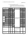
(1) List of supported communication library functions
The following table lists the functions supported for the communication library.
Web function item
Function
Overview
Remarks
Reads from a bit device (such as X, Y, or M) in 16-point units.
Corresponds to command 0401
Reads from a word device (such as D, R, T, or C) in one-point
(00 0) for QnA compatible 3E frame.
units.
Device Read
DevRead
Device Write
DevWrite
Writes to a word device (such as D, R, T, or C) in one-point
units.
Remote RUN
RmtRun
Requests a remote RUN operation to the CPU module.
Corresponds to command 1001 (0000)
for QnA compatible 3E frame.
Remote STOP
RmtStop
Requests a remote STOP operation to the CPU module.
Corresponds to command 1002 (0000)
for QnA compatible 3E frame.
Data Request
ReqCmd
Sends a user-specified command (an application data
(subheader + text) of the MC protocol), and receives the result.
Proxy Setting
ProxySet
Specify the proxy server when connecting an Ethernet module
via a proxy server.
Proxy Reset
ProxyReset
Resets the proxy setting.
Writes to a bit device (such as X, Y, or M) in 16-point units.
Corresponds to command 1401
(00 0) for QnA compatible 3E frame.
(2) Communication library functions
6
The following table lists the communication library functions.
Web function item
Function
BSTR
p = DevRead (HostName, NetNo, PcNo, CpuTime, DevCode, DevNo, DevNum, PassWord, RetType)
HostName: Connection target
Device Read
6-1
Argument
Input
NetNo: Network No.
Input
PcNo: PC No.
Input
CpuTime: CPU monitoring timer
Input
DevCode: Device code
Input
DevNo: Head device
Input
DevNum: Number of device
Input
PassWord: Password
Input
RetType: Execution result type (1: Actual data only; Other than 1: Normal execution result)
Input
*p: Pointer to the execution result character string
Output
6-1
6 COMMUNICATION LIBRARY FUNCTIONS
Web function item
MELSEC-Q/L
Function
BSTR
p = DevWrite (HostName, NetNo, PcNo, CpuTime, DevCode, DevNo, DevNum, DevData, PassWord)
HostName: Connection target
Device Write
Argument
BSTR
Input
PcNo: PC No.
Input
CpuTime: CPU monitoring timer
Input
DevCode: Device code
Input
DevNo: Head device
Input
DevNum: Number of device
Input
DevData: Write data
Input
PassWord: Password
Input
*p: Pointer to the execution result character string
Output
p = RmtRun (HostName, NetNo, PcNo, CpuTime, CpuNo, CmdMode, ClrMode, PassWord)
HostName: Connection target
Remote Run
Argument
BSTR
Remote Stop
Data Request
Proxy Setting
Proxy Reset
6-2
Input
CpuTime: CPU monitoring timer
Input
CpuNo: Target programmable controller (Request destination module I/O No.)
Input
CmdMode: Operation mode
Input
ClrMode: Clear mode
Input
PassWord: Password
Input
*p: Pointer to the execution result character string
Output
HostName: Connection target
Input
NetNo: Network No.
Input
PcNo: PC No.
Input
CpuTime: CPU monitoring timer
Input
CpuNo: Target programmable controller (Request destination module I/O No.)
Input
CmdMode: Operation mode
Input
PassWord: Password
Input
*p: Pointer to the execution result character string
Output
HostName: Connection target
Input
CmdData: Application data part (subheader + text (command))
Input
PassWord: Password
Input
RetType: Execution result type (1: Actual data only; Other than 1: Normal execution result)
Input
*p: Pointer to the execution result character string
Output
p = ProxySet (ProxyName, PortNo)
Argument
BSTR
Input
PcNo: PC No.
p = ReqCmd (HostName, CmdData, PassWord, RetType)
Argument
BSTR
Input
NetNo: Network No.
p = RmtStop (HostName, NetNo, PcNo, CpuTime, CpuNo, CmdMode, PassWord)
Argument
BSTR
Input
NetNo: Network No.
ProxyName: Proxy server address
Input
PortNo: HTTP port No.
Input
*p: Pointer to the execution result character string
Output
p = ProxyReset ( )
Argument
*p: Pointer to the execution result character string
Output
6-2
6
6 COMMUNICATION LIBRARY FUNCTIONS
MELSEC-Q/L
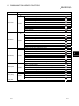
(3) Arguments used by the functions
The following table lists the arguments used by the communication library
functions.
All of the arguments of the communication library are specified using the same
character string as used for the communication settings of the MC protocol in
ASCII code.
Argument
Data type
ClrMode
Overview
Specifies the clear mode.
Setting range
Reference section
00, 01, and 02
Specifies the application data (subheader + text Enter according to
CmdData
(command)) of the MC protocol (QnA
compatible 3E frame).
CmdMode
Specifies the remote operation mode.
CpuTime
Specifies the CPU monitoring timer.
Specifies the target CPU (request destination
CpuNo
module I/O No.)
DevCode
Specifies the device code.
DevData
Specifies data for the number of device.
DevNo
Specifies the head device number.
DevNum
Specifies the number of device.
Character
PassWord
PcNo
PortNo
ProxyName
format.
0001, 0003
0000 to FFFF
0000 to 01FF,
03E0 to 03E3,
Refer to the reference
manual.
03FF
(Refer to item (a).)
(Refer to item (a).)
1 to 960
Specifies the IP address or host name of the
HostName
NetNo
the MC protocol
string
connection target Ethernet module.
Specifies the network No. to be routed thorough
last.
00 to EF, and FE
Refer to the reference
manual.
Specifies the remote password.
Specifies the PC No. of the access station.
01 to 40, 7D, 7E,
Refer to the reference
and FF
manual.
Specifies the HTTP port No.
Specifies the IP address or host name of the
proxy server.
Specifies the execution result type.
1: Actual data only
Returns only the application data (subheader
RetType
+ text (response)) returned from the CPU
module.
Other than 1: Normal execution result
Returns the data edited in the
communication library.
6-3
6-3
6 COMMUNICATION LIBRARY FUNCTIONS
(a)
Device
Device codes and head device numbers
The following table lists the device codes and head device numbers.
The devices that can be accessed using device memory read/write vary,
depending on the target CPU module. For details, refer to the reference
manual.
Device type
Bit
Word
Device
Device No. range
code
(at default assignment)
Special relay
SM
Special register
SD
Input relay
X
Output relay
Y
Internal relay
M
Latch relay
L
Annunciator
F
Edge relay
V
Link relay
B
Data register
D
Link register
W
Contact
Timer
Retentive
timer
Counter
TC
Current value
TN
Contact
SS
Coil
SC
Current value
SN
Contact
CS
Coil
CC
Current value
CN
Special link relay
SB
Special link register
SW
Step relay
S
Direct input
DX
Direct output
DY
File register
Notation
Decimal
Hexadecimal
TS
Coil
Index register
MELSEC-Q/L
Specify the number within the
device number range of the
module to be accessed.
Z
R
ZR
Binary code:
Specify the number within the
device number range of the
Extended data register
D
module to be accessed.
ASCII code:
000000 to 999999
Specify the number within the
Extended data register
W
device number range of the
module to be accessed.
6-4
6-4
6 COMMUNICATION LIBRARY FUNCTIONS
MELSEC-Q/L
(4) Return values of the functions
The following explains the return values of the communication library functions.
(a) A code for judging the execution result is added to the head of the return
value.
For normal completion, <!OK> is added.
For abnormal completion, <!NG> is added.
For ReqCmd, <!OK> is added in the case of an MC protocol error.
(b) A code for judging an error is added at abnormal completion.
1) In the case of an HTTP error, <!NG><!HTTP error “HTTP error code”>
is added.
2) In the case of a WinSock error, <!NG><!WinSock error “WinSock error
code”> is added.
3) In the case of an MC protocol error, <!NG><!MCP error “error code
(end code)”> is added.
Refer to either of the following manuals according to the error code,
verify the error content, and take an appropriate action.
<Error codes>
4FFFH or lower : The user's manual of the CPU module used
(Hardware Design, Maintenance and
Inspection)
C000H and higher : The user's manual (Basic)
4) In the case of a communication library error, an error message is
displayed.
(c) If the HTTP port is used or a remote password has been set in the CPU
module of access destination, create a program for remote password input
processing, using the error code for the following return value as a
condition. (For an example of how to describe a program for remote
password input processing, refer to Section 4.5.)
<!HTTP error 401>
(d) The following table lists examples of the return values of the communication
library functions.
Function
DevRead
DevWrite
RmtRun
RmtStop
Condition
Normal
completion
Normal completion
<!OK>- The execution result of Device Write -<BR>The normal completion.<BR>
Abnormal completion
<!NG><!MCP error C056>- The execution result of Device Write -<BR>The abnormal completion. C056<BR>
Normal completion
<!OK>- The execution result of Remote RUN -<BR>The normal completion.<BR>
Abnormal completion
<!NG><!MCP error 4B00>- The execution result of Remote RUN -<BR>The abnormal completion. 4B00<BR>
Normal completion
<!OK>- The execution result of Remote STOP -<BR>The normal completion.<BR>
Abnormal completion
<!NG><!MCP error 4B00>- The execution result of Remote STOP -<BR>The abnormal completion. 4B00<BR>
Abnormal
completion
6-5
<!OK>123456789ABC1234
<!NG><!MCP error C056>- The execution result of Device Read -<BR>The abnormal completion. C056<BR>
ReqCmd
ProxyReset
RetType = “1”
Return value (example)
<!OK>- The execution result of Device Read -<BR>The normal completion.<BR>Device code D*<BR>Device
000000<BR>Number of device 4<BR>Reading data 123456789ABC1234
Abnormal completion
Normal
completion
ProxySet
RetType = other
than “1”
RetType = other
than “1”
<!OK>- The execution result of Data Request -<BR>The MC protocol normal
completion.<BR>D00000FF03FF0000140000123456789ABC1234<BR>
RetType = “1”
<!OK>D00000FF03FF0000140000123456789ABC1234
RetType = other
than “1”
<!OK>- The execution result of Data Request -<BR>The MC protocol abnormal completion.
C056<BR>D00000FF03FF000016C05600FF03FF0004010000<BR>
RetType = “1”
<!OK>D00000FF03FF000016C05600FF03FF0004010000
Normal completion
<!OK>- The proxy setting -<BR>The proxy setting completion.<BR>
Abnormal completion
<!NG>- The communication library error -<BR>Check the setting value of the proxy.<BR>
Normal completion
<!OK>- The proxy setting -<BR>The proxy setting cancellation.<BR>
Abnormal completion
<!NG>- The communication library error -<BR>The proxy information is not set.<BR>
6-5
INDEX
I
[C]
Communication Library argument ........... 6-3
Communication Library functions............ 6-1
Configuration of files on the Sample
screen ................................................... 4-15
[W]
Web browser ................................. A-10, 2-2
Web function items available on the
Sample screen ........................................4-1
Web server.................................... A-10, 2-2
Web server software ............................ A-10
[D]
Device code ............................................ 6-4
Decompressing the file............................ 3-3
[F]
File structure............................................ 3-3
[H]
Head device numbers ............................. 6-4
How to obtain the Communication
library ...................................................... 3-2
How to obtain the Sample screen ........... 3-2
[M]
Manual's use ...........................................A-9
MC protocol...........................................A-10
[O]
Overview of web function ........................ 1-1
[R]
Registering the Communication library ... 3-4
Related Manuals .....................................A-8
Remote password check......................... 1-4
[S]
Setup the file ........................................... 3-3
Supported Communication library
function.................................................... 6-1
[U]
Utilizing the Web server .......................... 1-3
[V]
Verifying the Web function using a Sample
screen ..................................................... 4-1
Index - 1
Index - 1
I
MEMO
Index - 2
Index - 2
WARRANTY
Please confirm the following product warranty details before using this product.
1. Gratis Warranty Term and Gratis Warranty Range
If any faults or defects (hereinafter "Failure") found to be the responsibility of Mitsubishi occurs during use of the product
within the gratis warranty term, the product shall be repaired at no cost via the sales representative or Mitsubishi Service
Company.
However, if repairs are required onsite at domestic or overseas location, expenses to send an engineer will be solely at
the customer’s discretion. Mitsubishi shall not be held responsible for any re-commissioning, maintenance, or testing
on-site that involves replacement of the failed module.
[Gratis Warranty Term]
The gratis warranty term of the product shall be for one year after the date of purchase or delivery to a designated place.
Note that after manufacture and shipment from Mitsubishi, the maximum distribution period shall be six (6) months, and
the longest gratis warranty term after manufacturing shall be eighteen (18) months. The gratis warranty term of repair
parts shall not exceed the gratis warranty term before repairs.
[Gratis Warranty Range]
(1) The range shall be limited to normal use within the usage state, usage methods and usage environment, etc., which
follow the conditions and precautions, etc., given in the instruction manual, user's manual and caution labels on the
product.
(2) Even within the gratis warranty term, repairs shall be charged for in the following cases.
1. Failure occurring from inappropriate storage or handling, carelessness or negligence by the user. Failure caused
by the user's hardware or software design.
2. Failure caused by unapproved modifications, etc., to the product by the user.
3. When the Mitsubishi product is assembled into a user's device, Failure that could have been avoided if functions
or structures, judged as necessary in the legal safety measures the user's device is subject to or as necessary by
industry standards, had been provided.
4. Failure that could have been avoided if consumable parts (battery, backlight, fuse, etc.) designated in the
instruction manual had been correctly serviced or replaced.
5. Failure caused by external irresistible forces such as fires or abnormal voltages, and Failure caused by force
majeure such as earthquakes, lightning, wind and water damage.
6. Failure caused by reasons unpredictable by scientific technology standards at time of shipment from Mitsubishi.
7. Any other failure found not to be the responsibility of Mitsubishi or that admitted not to be so by the user.
2. Onerous repair term after discontinuation of production
(1) Mitsubishi shall accept onerous product repairs for seven (7) years after production of the product is discontinued.
Discontinuation of production shall be notified with Mitsubishi Technical Bulletins, etc.
(2) Product supply (including repair parts) is not available after production is discontinued.
3. Overseas service
Overseas, repairs shall be accepted by Mitsubishi's local overseas FA Center. Note that the repair conditions at each FA
Center may differ.
4. Exclusion of loss in opportunity and secondary loss from warranty liability
Regardless of the gratis warranty term, Mitsubishi shall not be liable for compensation of damages caused by any cause
found not to be the responsibility of Mitsubishi, loss in opportunity, lost profits incurred to the user by Failures of
Mitsubishi products, special damages and secondary damages whether foreseeable or not, compensation for accidents,
and compensation for damages to products other than Mitsubishi products, replacement by the user, maintenance of onsite equipment, start-up test run and other tasks.
5. Changes in product specifications
The specifications given in the catalogs, manuals or technical documents are subject to change without prior notice.
Microsoft, Windows, Windows NT, and Windows Vista are registered trademarks of Microsoft Corporation in the United
States and other countries.
Pentium is a trademark of Intel Corporation in the United States and other countries.
Ethernet is a trademark of Xerox Corporation.
All other company names and product names used in this manual are trademarks or registered trademarks of their
respective companies.
SH (NA)-080180-F