1
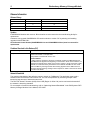
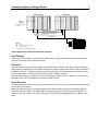
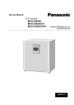
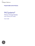
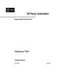
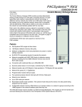
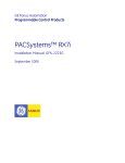
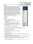
PACSystems™ RX7i
IC698RMX016-DC
GFK-2324B
June 7, 2005
Redundancy Memory Xchange Module
The Redundancy Memory Xchange (RMX) module operates as a node on a reflective memory
network or as a dedicated link between CPUs in a redundant RX7i system. When the RMX is
not being used as a link in a redundancy system, it is functionally identical to the IC698CMX016
module. Each node in the network can be any reflective memory device that is compatible with
the 5565 family. Whenever data is written to one node, all nodes on the network are
automatically updated with the new data.
RMX016
OK
LINK OK
When used as a node on a reflective memory network, the RMX module provides deterministic
sharing of data among PLCs and other computing devices on a high-speed fiber optic network.
A reflective memory network can contain up to 256 nodes.
Each node in the reflective memory network is connected in a daisy-chained loop using fiber
optic cables. The transmitter of the first node is tied to the receiver of the second. The
transmitter of the second node is tied to the receiver of the third node, and so on, until the loop
is completed at the receiver of the first node.
When used in a CPU redundancy system, the RMX modules provide a path for transferring data
between the two redundancy CPUs in the redundant system. A complete communications path
consists of one RMX in the primary unit, one RMX in the secondary unit, and two high-speed
fiber optic cables connecting them to each other. This must be a two-node ring: no other
reflective memory nodes are allowed to be part of this fiber optic network.
LOCAL
READY
ACTIVE
REMOTE
READY
ACTIVE
ROLE
SWITCH
GE Fanuc strongly recommends two redundancy links (for a total of four RMX modules) be
configured and installed. Optionally, systems can be configured for a single redundancy link (for
a total of two RMX modules).
1
0
When the RMX is being used as link in a redundancy system, it cannot be used as a generalpurpose Memory Xchange module. For details on the operation of a PACSystems CPU
redundancy system, refer to the PACSystems Hot Standby CPU Redundancy User’s Manual,
GFK-2308.
A PACSystems RX7i main rack supports a maximum of four Memory Xchange modules in any
combination of RMX016 and CMX016 modules. A maximum of two RMX modules can be
configured as redundancy communication links.
OWN DATA
SIGNAL DETECT
Features
■
PACSystems RX7i single slot form factor.
■
16 Mbytes reflective memory with parity.*
■
Software configuration of all node parameters (no jumper or switch settings required).*
■
High-speed easy-to-use 2.12 Gbaud fiber-optic network.
■
No RX7i CPU processing required to operate the network.
■
Network-compatible with VMIC 5565 family of reflective memory devices.
■
Connection with multimode fiber up to 300m /984.25ft.
■
Dynamic packet sizes of 4 to 64 bytes, controlled by the Memory Xchange module.
■
Maximum network transfer rate of 43 Mbyte/s (4 byte packets) to 174 Mbyte/s (64 byte
packets)
■
Programmable VMEbus interrupt output.*
■
Four general purpose network interrupts with 32 bits of data each.*
■
Network error detection.
■
Up to 256 nodes per network.*
■
Redundant transfer mode operation. This optional mode reduces the chance of a data
packet being dropped from the network.*
■
Configurable network memory offset allows you to assign nodes on a network to groups
according to the 16MB segment in the network address space that they use.*
*Not available when operating as a redundancy link in a CPU redundancy system.
TX
RX
2
Redundancy Memory Xchange Module
GFK-2324B
Release Information
Release History
Release
Hardware Version
Firmware Version
DC
D
C
CB
C
B
BA
B
A
AA (Initial Release)
A
A
Updates
IC698RMX016 Modules with versions -BA and earlier must be returned to the manufacturing facility for
replacement.
Customers can upgrade IC698RMX016-CB version modules to version -DC by ordering and installing
upgrade kit 44A753080-G01.
All Conformal Coated boards (IC698RMX016CA-xx and IC698CMX016CA-xx) must be returned for
replacement.
Problems Resolved in this Release (DC)
Subject
Corrupted Data
Description
In earlier versions, certain sequences of data patterns, when written to or read from the
module would result in corrupted data.
This problem is resolved with version –DC.
Problem Details:
In earlier versions, the Memory Xchange module did not latch the VME address lines
and VME AM code signals at the beginning of a transaction. Under most conditions, not
latching these signals had no effect on the system. However, certain sequences of data
patterns can cause momentary transactions on the address and AM lines. This could
lead to the Memory Xchange module disconnecting signals from the VME bus that it
should be driving/monitoring, leading to data corruption on either a read from the board
or a write to the board.
Network Bandwidth
The maximum bandwidth of the reflective memory network is 174Mbytes/s. The application must avoid a
situation where the transmit FIFO becomes full. You can accomplish this by not having multiple nodes
transmit a large amount of data at the same time.
The RX FIFO Almost Full status (bit 09) of the LISR (Region 2, offset 10h) can be monitored to determine if
the network is becoming saturated.
For an example of network load balancing, refer to “Optimizing Network Bandwidth” in the PACSystems RX7i
Memory Xchange Modules User’s Manual, GFK-2300.
Redundancy Memory Xchange Module
3
GFK-2324B
C
P
U
R R
M M
X X
Primary Unit
Power Supply
RX7i
(Rack 0)
Power Supply
Secondary Unit
G
B
C
C
P
U
R R
M M
X X
G
B
C
Required fan assembly
not shown.
30
31
High-speed fiber optic link*
High-speed fiber optic link*
Genius Bus
Remote Drop
Legend
CPU RMX GBC -
RX7i CPU
Redundancy Memory Xchange Module
Genius Bus Controller
PS I I I I I I I I
SC O O O O O O O O
A
N
N
E
R
*Supports up to 30.48m/100ft fiber optic cable.
Sample PACSystems RX7i CPU Redundancy System
User Features
The front panel of the RMX module has eight LED indicators, a toggle switch that can be used to manually
request a role switch, and an optical transceiver.
Role Switch
The Role switch is a spring loaded two-position switch that rests in the OFF state. When the RMX module is
being used as a redundancy link, this switch allows you to manually switch control from the active controller to
the backup controller. To initiate the switching of roles, lift the switch to the ON position for at least 1 second.
The role switch state is de-bounced and filtered to prevent accidental activation.
When the RMX module is used as a node in a general-purpose reflective memory network (i.e. not used as a
redundancy link), the Role switch has no effect on module operation.
Optical Transceiver
The optical transceiver has two “LC” type fiber optic ports. The port labeled “TX” is the transmitter and the port
labeled “RX” is the receiver.
Memory Xchange modules are networked together using either simplex (single fiber) or duplex (dual fiber)
multimode fiber optic cables. The specific cable construction depends on your operating environment. For
details on fiber optic cables, refer to the PACSystems RX7i Memory Xchange Modules User’s Manual, GFK2300.
4
Redundancy Memory Xchange Module
GFK-2324B
LEDs
All front panel LED indicators are green. The default state of all LED indicators after reset is OFF.
LED Label
Description
OK
ON indicates the module is functioning properly.
LINK OK
When not used as a redundancy link, ON indicates the module is configured.
When used as a redundancy link, ON indicates the link is functioning properly.
LOCAL READY
ON indicates the local unit is ready.
LOCAL ACTIVE
ON indicates the local unit is active.
REMOTE READY
ON indicates the remote unit is ready.
REMOTE ACTIVE
ON indicates the remote unit is active.
OWN DATA
ON indicates the module has received its own data packet from the network at least once.
SIGNAL DETECT
ON indicates the receiver is detecting a fiber optic signal
Installation
Make sure you have the items listed below before you begin.
■
A PACSystems RX7i CPU with release 2.00 or higher firmware
■
A PACSystems Rx7i CPU rack with power supply.
■
Programming software: Machine Edition – Logic Developer PLC, version 4.5 or later (and a PCcompatible computer).
Cables. For details, see “Fiber optic Cables and Connectors” in the PACSystems RX7i Memory Xchange
Modules User’s Manual, GFK-2300.
■
Note:
RX7i systems that include one or more Memory Xchange modules must be installed in a metal
enclosure with conduit or equivalent to meet radiated emission standards. For details, refer to the
PACSystems RX7i Installation Manual, GFK-2223.
Installing the RMX Module in an RX7i Rack
Warning
Do not insert or remove modules with power applied. This could cause the CPU to stop, damage the
module, or result in personal injury.
Memory modules must only be installed in the main (Rack 0) RX7i rack.
Note: It is recommended that the RMX modules be installed in slots 3 and 4 of the main rack. This gives
VME interrupt request priority to the RMX modules. Although this configuration is recommended, it is
not required that the RMX modules be located in slots 3 and 4.
1.
Make sure rack power is off.
2.
Slide the module into the slot for which it was configured in the system.
3.
Press the board firmly in place, but do not force the board. Tighten the screws on the top and bottom of
the faceplate.
4.
Connect the cables to the TX and RX connectors.
5.
Route the fiber optic cable from TX to the RX connector of the next node in the ring. Connect the cable
from that board’s TX to the RX connector of the next node. Repeat this step until the last node in the ring
routes its TX to the RX of the first node.
6.
Turn on power to the RX7i rack.
Redundancy Memory Xchange Module
5
GFK-2324B
Configuration
The RMX module initially powers up in an unconfigured state with its optical transmitter disabled. The module
cannot operate on a network until the RX7i CPU has sent a hardware configuration to the module.
For general-purpose reflective memory operation, you can configure the following parameters in the hardware
configuration: Node ID, Redundant Transfer Mode, Rogue Master, Network Memory Offset, and Interrupt
enable. (If Redundant Link operation is selected, these parameters are set by the CPU and are not
configurable.)
When the RMX is used as a general-purpose reflective memory module, additional functions beyond the
basic read and write operations, including enabling interrupts, reading interrupt status, enabling parity, and
reading parity errors, can be performed by user logic. For details on accessing these advanced functions,
refer to the PACSystems RX7i Memory Xchange Modules User’s Manual, GFK-2300.
Related Publications
PACSystems RX7i CPU Reference Manual, GFK-2222
PACSystems RX7i Installation Manual, GFK-2223
PACSystems RX7i Memory Xchange Modules User’s Manual, GFK-2300
PACSystems RX7i CPU Redundancy User’s Manual, GFK-2308
Proficy™ Machine Edition Logic Developer-PLC Getting Started, GFK-1918
Specifications*
Physical size
PCB: 6.299” W x 9.187” H
Packet size
Dynamic, automatically controlled by Memory Xchange module
User memory
16MB SDRAM
Operating voltage
+5VDC (from power supply)
Current requirements
1.8A
Connectors
■
Fiber optic LC type, conforms to IEC 61754-20
■
Zirconium ceramic ferrule
■
Insertion loss: 0.35 dB (maximum)
■
Return loss: -30dB
■
Temperature Range: -20°C to +85°C
* For environmental specifications and compliance to standards (for example, FCC or
European Union Directives), refer to the PACSystems RX7i Installation Manual, GFK2223.
6
Redundancy Memory Xchange Module
GFK-2324B
Ordering Information
Description
Redundancy Memory Xchange Module for RX7i
Catalog Number
IC698RMX016
Control Memory Xchange Module for RX7i
IC698CMX016
Fiber Optic Cables
VMICBL-000-F5-0XX,
where 0XX is used to distinguish
different lengths
RX7i VME 700MHz CPU with Redundancy
IC698CRE020
Lithium Battery pack
IC698ACC701
Rack Fan Assembly, 120VAC
Rack Fan Assembly, 240VAC
Rack Fan Assembly, 24VDC
IC697ACC721
IC697ACC724
IC697ACC744
RX7i PLC Power Supply, 85 to 264 VAC at 47 to 63 Hz Input, 100 watt output
IC698PSA100
RX7i PLC Power Supply, 85 to 264 VAC at 47 to 63 Hz Input, 350 watt output
IC698PSA350
[Optional] RS-232 cable; also Station Manager cable for Ethernet interface
IC200CBL001
The following information is for products bearing the UL marking for Hazardous Locations:
WARNING - EXPLOSION HAZARD - SUBSTITUTION OF COMPONENTS MAY IMPAIR SUITABILITY
FOR CLASS I, DIVISION 2.
WARNING - EXPLOSION HAZARD - WHEN IN HAZARDOUS LOCATIONS, TURN OFF POWER
BEFORE REPLACING OR WIRING MODULES.
WARNING - EXPLOSION HAZARD - DO NOT DISCONNECT EQUIPMENT UNLESS POWER HAS
BEEN SWITCHED OFF OR THE AREA IS KNOWN TO BE NONHAZARDOUS.
EQUIPMENT LABELED WITH REFERENCE TO CLASS I, GROUPS A, B, C, & D, DIV. 2 HAZARDOUS
LOCATIONS IS SUITABLE FOR USE IN CLASS I, DIVISION 2, GROUPS A, B, C, D OR NONHAZARDOUS LOCATIONS ONLY.