1
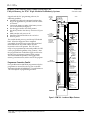
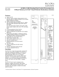
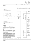
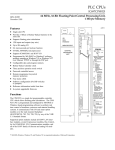
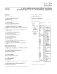
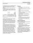
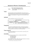
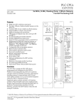
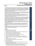
This Datasheet for the
IC697CPM790
GMR Redundancy CPU, 486, 2K Triplex (voted) I/O.
http://www.cimtecautomation.com/parts/p-14778-ic697cpm790.aspx
Provides the wiring diagrams and installation guidelines for this GE Series 90-30
module.
For further information, please contact Cimtec Technical Support at
1-866-599-6507
[email protected]
1
PLC CPUs
IC697CPM790
27
GFK-1215B
November 1999
64 MHz, 32-Bit Floating Point Central Processing Unit,
1 Mbyte Memory, for IC66* Triple Modular Redundancy Systems
64 MHz, 32-Bit Floating Point Central Processing Unit,
1 Mbyte Memory, for IC66* Triple Modular Redundancy Systems (IC697CPM790)
datasheet GFK-1215B
Features
D Single slot CPU
D Provides 1 Mbyte of battery-backed memory in the
D
D
D
D
D
D
D
D
D
D
D
D
D
D
D
same slot (up to 512 Kbytes available for use by
ladder diagram application program)
Supports floating point calculations
Up to 12K discrete inputs and outputs (any mix simplex mode only); 2048 voted discrete inputs, 2048
voted discrete outputs
Up to 8K analog inputs (simplex mode only) and
8K analog outputs (simplex mode only); 1024 voted
analog inputs
0.4 microseconds per boolean function
64 MHz, 80486DX2 microprocessor
Supports IC660/IC661 I/O (and IC697 I/O in simplex mode only)
Programmed by MS-DOSr, or Windowsr software
products running on Windowsr 95 or Windows
NTr over Ethernet TCP/IP or through the SNP
port.
Configurable data and program memory
Battery-backed calendar clock
Three position operation mode switch
Password controlled access
Remote programmer keyswitch memory
protection
Four status LEDs
Software configuration (No DIP switches
or jumpers)
Reference information inside front door
In-system upgradable firmware
Functions
The CPM 790 is a single slot programmable controller
CPU which allows floating point calculations. The CPM
790 is programmed and configured with MS-DOS or
Windows based programming software for use in
Emergency Shut-Down (ESD), fire and gas, and other
critical control applications. It communicates with I/O
and smart option modules over the rack mounted
backplane (IC697CHS750, 782, 783, 790, 791) by way of
the VME C.1 Standard format.
ÎÎ
ÎÎÎÎÎ
Î
ÎÎ
Î
Î
ÎÎÎÎÎ
Î
ÎÎ
Î
Î
Î
ÎÎÎÎÎ
Î
Î
Î
Î
ÎÎÎ
ÎÎ
ÎÎ
ÎÎÎÎÎ Î
Î
Î
ÎÎÎ
ÎÎ
ÎÎ
ÎÎÎÎÎ
Î
Î
Î
ÎÎÎ
ÎÎÎÎÎ
Î
Î
Î
ÎÎÎ
ÎÎ
ÎÎ
Î
ÎÎÎÎÎ
Î
Î
Î
ÎÎÎ
ÎÎ
ÎÎ
Î
ÎÎÎÎÎ
Î
Î
Î
ÎÎÎ
ÎÎÎÎÎ
Î
Î
Î
ÎÎÎÎÎ
Î
Î
Î
ÎÎ
ÎÎÎÎÎ
Î
Î
ÎÎ
ÎÎÎÎÎ Î
Î
Î
Î
ÎÎ
ÎÎÎÎÎ
Î
Î
Î
ÎÎÎÎÎ
Î
Î
Î
ÎÎÎÎÎ
Î
Î
Î
ÎÎ
ÎÎÎÎÎ
Î
Î
Î
ÎÎ
ÎÎÎÎÎ
Î
Î
Î
ÎÎÎÎÎ
Î
Î
Î
ÎÎÎÎÎ
Î
Î
Î
ÎÎÎÎÎ
Î
Î
Î
ÎÎÎÎÎ
Î
Î
Î
ÎÎÎÎÎ
Î
Î
Î
ÎÎÎÎÎ
Î
ÎÎ
ÎÎÎÎÎ
Î
Î
Î
ÎÎÎÎÎ
Î
Î
Î
ÎÎÎÎÎ ÎÎÎ ÎÎ
ÎÎÎÎÎ
Î
Î
Î
ÎÎ
ÎÎÎÎÎ Î
Î
a47080
OK
RUN
ENABLED
MEM PROTECT
CENTRAL
PROCESSOR
UNIT
B
A
T
T
E
R
Y
CPM 790
TOP
OFF
ON
REMOTE PROGRAMMER
MEMORY PROTECT
KEY POSITION
FRONT
MODULE OK
RUN
OUTPUTS
ENABLED
MEMORY
PROTECT
REMOTE
PROGRAMMER
ONLY
ON = OK, ENABLED,
PROTECTED
RUN WITH
OUTPUTS
ENABLED
RUN WITH
OUTPUTS
DISABLED
STOP
BATTERY
CONNECTORS
INSTALL NEW
BATTERY BEFORE
UNPLUGGING OLD
BATTERY. USE
IC697ACC701
MODULE FUNCTION
64 MHz 32 BIT CENTRAL
PROCESSING UNIT WITH
FLOATING POINT MATH
COPROCESSOR, IN-SYSTEM
UPGRADEABLE FIRMWARE.
SERIAL PORT
RS-485
COMPATIBLE
USE THIS MODULE
IN SLOT 1 ONLY.
MODULE
IC697CPM790
LABEL
44A726758-149R01
The CPM 790 must be used in conjunction with a
Standalone C program which provides Triple Modular
Redundancy (TMR) operating and autotest routines. It
will not operate unless this program is included in the
loaded application program.
r MS-DOS, Windows, Windows 95, and Windows NT are registered trademarks of Microsoft Corporation.
t
Series 90 -70 Programmable Controller Data Sheet Manual
GFK-0600F
27-1
PLC CPUs
2
GFK-1215B
November 1999
64 MHz, 32-Bit Floating Point Central Processing Unit,
1 Mbyte Memory, for IC66* Triple Modular Redundancy Systems
For detailed information on TMR systems, see
Reference 4, the IC66* Modular Redundancy Flexible
Triple Modular Redundant (TMR) System User’s Manual.
Supported option modules include IC697 LAN Interface
modules, Programmable Coprocessor, Alphanumeric
Display Coprocessor, Bus Controller for IC660/661 I/O
products, Communications modules, I/O Link Interface,
and all of the IC697 family of discrete and analog I/O
modules.
a47059
Triple PLCs
Triple Genius Busses
Load
Triple Input Sensors
Figure 1. Typical GMR System Configuration
User Memory
Program and data memory for the CPM 790 is provided
by a memory board with 1 Mbyte of battery-backed
CMOS RAM. 512 Kbytes of this memory is available for the
user’s application program and data. This memory board is
an integral part of the CPM 790 module and is included
with the module.
Flash Memory
This module uses flash memory for storage of the
operating system firmware (this module does not support storage of user program in the flash memory). This
allows updates of the firmware without disassembling the module or replacing EPROMs. The operating system firmware is updated by connecting a
PC compatible computer to the module’s serial port
and running the Loader software included with the
firmware floppy disk.
Operation, Protection, and Module Status
Operation of this module can be controlled by the
three-position RUN/STOP switch or remotely by an
attached programmer and programming software.
Program and configuration data can be locked
through software passwords or manually by the
memory protect keyswitch. When the key is in the
protected position, program and configuration data can
27-2
only be changed by a programmer connected parallel
only (to the Bus Transmitter module). The status of a
CPU is indicated by the four green LEDs on the front
of the module.
Operating Temperature
The CPM 790 requires forced air cooling for proper
operation in ambient temperatures greater than 40_C
(104_F). A fan capable of 70 CFM (including filters)
should be located beneath slot 1 of the rack containing
the CPU.
Fan assemblies (IC697ACC721, IC697ACC724, and
IC697ACC744) can be ordered for direct mounting on
the IC697 rack. Refer to the applicable Programmable
Controller Installation Manual for detailed information.
Installation
It is the responsibility of the OEM, system integrator, or
end user to properly install the PLC equipment for safe
and reliable operation. Product manuals provide
detailed information about installation, startup, and
proper use of the PLC equipment. The installation
manual, shipped with your PLC programming software,
describes how to properly install the equipment. If the
PLC installation must comply with supported standards,
such as FCC or CE Directives, please refer to the
Installation Requirements for Conformance to Standards,
t
Series 90 -70 Programmable Controller Data Sheet Manual
GFK-0600F
PLC CPUs
3
GFK-1215B
November 1999
64 MHz, 32-Bit Floating Point Central Processing Unit,
1 Mbyte Memory, for IC66* Triple Modular Redundancy Systems
shipped with the PLC programming software, for
additional guidelines.
D Installation should not be attempted without referring to the applicable Programmable Controller Installation Manual.
D Connect the battery to either of the battery connectors on the module (see Figure 2).
D Put the toggle switch in the STOP position.
D Put the keyswitch in the Memory Protection OFF position.
D Make sure that rack power is off.
D Install the CPM 790 module in slot 1 of rack 0.
D Turn on power.
The module should power up and the top LED should
blink. When the diagnostics have completed
successfully, the top LED stays on and the second and
third LEDs are off. The fourth LED is off if the
keyswitch is in the OFF position. The CPU is now
ready to be programmed (if connected parallel, the CPU
can be programmed regardless of key position). After
the program has been verified the toggle switch can be
moved to the appropriate operation mode position.
The LEDs indicate the position of the toggle switch,
memory protection status, and the state of the program.
Programmer Connection, Parallel
MEMORY
PROTECT
KEY
SWITCH
OPEN
REPLACEMENT
BATTERY
CONNECTOR
CURRENTLY
INSTALLED
BATTERY
CONNECTOR
a47081
ÎÎ
ÎÎ ÎÎ
ÎÎ
ÎÎ
ÎÎ ÎÎÎÎ
Î
ÎÎ
Î
Î
ÎÎ
Î
ÎÎ
ÎÎ
Î
ÎÎ
Î
ÎÎÎÎ
Î
ÎÎ
Î
ÎÎ
ÎÎ
Î
ÎÎ
Î
ÎÎ
ÎÎ
Î
ÎÎ
Î
ÎÎ
Î
ÎÎ
ÎÎÎÎ
Î
ÎÎ
Î
ÎÎ
Î
Î
Î
ÎÎ
Î
Î
Î
ÎÎ
Î
Î
Î
ÎÎ
Î
Î
Î
ÎÎ
Î
Î
ÎÎ
Î
Î
ÎÎ
Î
Î
ÎÎ
Î
Î
ÎÎ
Î
Î
ÎÎ
Î
Î
ÎÎ
Î
Î
ÎÎ
Î
Î
ÎÎ
Î
Î
ÎÎ
Î
ÎÎ
ÎÎ
Î
ÎÎ
Î
ÎÎ
ÎÎ
Î
ÎÎ
Î
Î
ÎÎ
Î
ÎÎ
ÎÎ
ÎÎ ÎÎ
B
A
T
T
E
R
Y
CPM 790
TOP
OFF
ON
REMOTE PROGRAMMER
MEMORY PROTECT
KEY POSITION
FRONT
MODULE OK
RUN
OUTPUTS
ENABLED
MEMORY
PROTECT
REMOTE
PROGRAMMER
ONLY
ON = OK, ENABLED,
PROTECTED
RUN WITH
OUTPUTS
ENABLED
RUN WITH
OUTPUTS
DISABLED
1 MBYTE
MEMORY BOARD
For a parallel interface (MS-DOS programmer only) the
programmer is connected to the top port on the Bus
Transmitter Module (IC697BEM713). Consult Reference
1 for a description of programming functions.
STOP
BATTERY
CONNECTORS
INSTALL NEW
BATTERY BEFORE
UNPLUGGING OLD
BATTERY. USE
IC697ACC701
MODULE FUNCTION
64 MHz 32 BIT CENTRAL
PROCESSING UNIT WITH
FLOATING POINT MATH
COPROCESSOR, IN-SYSTEM
UPGRADEABLE FIRMWARE
SERIAL PORT
RS-485
COMPATIBLE
USE THIS MODULE
IN SLOT 1 ONLY
MODULE
IC697CPM790
LABEL
44A726758–149R01
CPM 790
Figure 2. CPM 790 - Location of Major Features
t
Series 90 -70 Programmable Controller Data Sheet Manual
GFK-0600F
27-3
PLC CPUs
4
GFK-1215B
November 1999
64 MHz, 32-Bit Floating Point Central Processing Unit,
1 Mbyte Memory, for IC66* Triple Modular Redundancy Systems
a47100
PLC A
C
P
U
PLC B
PLC C
C
P
U
C
P
U
Multidrop Cable
RS–232/422
Converter
Multidrop cable is catalog number
IC690CBL714 (1 cable). Two cables
are needed for 3 CPUs.
Figure 3. System Configuration, Serial Connection to Programmer
Serial Port
The 15-pin D-connector provides the connection to an
RS-485 compatible serial port on the CPU (see Figure 3).
This port provides a serial connection to a Work Station
Interface board installed in the programming computer.
The serial connection can also be made from the serial
port on the CPU to the serial port on the programming
computer, or other serial device, through the
RS-422/RS-485 to RS-232 Converter (IC690ACC900) or
RS-232 to RS-422 Miniconverter (IC690ACC901). This
connection can be made with available cables or you
may build cables to fit the needs of your particular
application. See reference 3 for more information on
serial communications.
For more detailed information on configuration of TMR
systems and communications between PLCs in the
27-4
system, refer to the Modular Redundancy Flexible Triple
Modular Redundant (TMR) System User’s Manual.
Programmer Connection, Ethernet TCP/IP
Connecting your programmer via an Ethernet TCP/IP
network requires installation of an Ethernet Interface
module in the PLC. This can be either the Ethernet
Controller, IC697CMM741, or Ethernet Interface (Type
2), IC697CMM742. Before connecting your
programmer and PLC to the Ethernet TCP/IP network
you must set the IP address in the Ethernet Interface.
After setting the IP address, connect the PLC and the
programmer running Windows software to the
Ethernet Interface.
For more detailed information on Ethernet TCP/IP,
refer to the TCP/IP Ethernet Communications (Type 2)
User’s Manual, and the Windows programming
manual, GFK-1295.
t
Series 90 -70 Programmable Controller Data Sheet Manual
GFK-0600F
PLC CPUs
5
64 MHz, 32-Bit Floating Point Central Processing Unit,
1 Mbyte Memory, for IC66* Triple Modular Redundancy Systems
GFK-1215B
November 1999
Configuration
The IC697 CPU and I/O system is configured with
MS-DOS or Windows based programming software.
There are no DIP switches or jumpers used to
configure the system. The CPU verifies the actual
module and rack configuration at power-up and
periodically during operation. The actual
configuration must be the same as the programmed
configuration. Deviations are reported to the CPU
alarm processor function for configured fault
response. Consult Reference 1 for a description of
configuration functions.
Battery
A lithium battery (IC697ACC701) is installed as shown
in Figure 2. This battery maintains program and data
memory when power is removed and operates the
calendar clock. Be sure to install the new battery
before removing the old battery. If during power-up
diagnostics a low battery is detected, the MODULE
OK LED (top LED) will not stay on. Specific
indication of a low battery state is detailed in
Reference 2.
Removing a Module
The instructions below should be followed when
removing a module from its slot in a rack.
D
Grasp the board firmly at the top and bottom of
the board cover with your thumbs on the front of
the cover and your fingers on the plastic clips on
the back of the cover.
D
Squeeze the rack clips on the back of the cover
with your fingers to disengage the clip from the
rack rail and pull the board firmly to remove it
from the backplane connector.
D
Slide the board along the card guide and remove
it from the rack.
Table 1. References
Reference
t
Title
1
Programming Software User’s Manual
2
Programmable Controller Reference Manual
3
Programmable Controller Installation Manual
4
IC660/IC661 Modular Redundancy Flexible Triple Modular
Redundant (TMR) System User’s Manual
Series 90 -70 Programmable Controller Data Sheet Manual
GFK-0600F
27-5
PLC CPUs
6
GFK-1215B
November 1999
64 MHz, 32-Bit Floating Point Central Processing Unit,
1 Mbyte Memory, for IC66* Triple Modular Redundancy Systems
Table 2. Specifications for IC697CPM790 [
Battery
Shelf life
10 years at 20_ C (68_ F)
Memory retention
6 months nominal without applied power.
Current required from 5V bus
3.3 Amps nominal
Operating Temperature
0 to 60_C (32_F to 140_F); 70 CFM forced air required
0 to 40_C (32_F to 104_F); without forced air
Time of Day Clock accuracy
" 3.5 seconds per day maximum
Elapsed Time Clock (internal timing) accuracy
" .01% maximum
Serial Port
RS422/485 compatible
Programmer Serial Attachment
VME
System designed to support the VME standard C.1
[ Refer to GFK-0867B, or later for product standards and general specifications.
Table 3. Ordering Information
Description
Catalog Number
Central Processing Unit
64 MHz, 32-Bit, Floating Point, 1 Mbyte Memory
For IC66* Triple Modular Redundancy Systems
IC697CPM790
Lithium Battery
IC697ACC701
Rack Fan Assembly, 120 VAC
Rack Fan Assembly, 240 VAC
Rack Fan Assembly, 24 VDC
IC697ACC721
IC697ACC724
IC697ACC744
Note: For Conformal Coat option, or Low Temperature Testing option please
consult the factory for price and availability.
27-6
t
Series 90 -70 Programmable Controller Data Sheet Manual
GFK-0600F