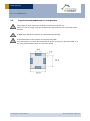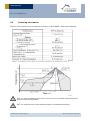
1
USER MANUAL V1.4 ECT 310 Perpetuum Module EnOcean powered by Thermal Energy Covered by at least following patents: W098/36395 | DE 10025561 | DE 10062028 | DE 10150128 DE 10155125 | DE 10063305 | DE 10301678 | DE29712270.3 W O00/043802 | DE 202004005837.5 | EP 1389358 | US 7,005,778 B2 EP 1550202 | US 7,019,241 B2 | DE 10256942.8 | DE 10256942.8 | DE 10256940 | DE 10315765 | DE 10315765 Further patents pending: http://www.enocean.com/en/patents/ EnOcean GmbH Kolpingring 18a 82041 Oberhaching Germany Phone +49.89.67 34 689-0 Fax +49.89.67 34 689-50 [email protected] www.enocean.com Subject to modification ECT 310 User Manual January 17, 2012 Page 1/20 USER MANUAL ECT 310 PERPETUUM REVISION HISTORY The following major modifications and improvements have been made to the first version of this document: No 1.0 1.1 1.2 1.3 1.4 Major Changes Initial version Major changes: I/O diagram in Chapter 1.3 added. Physical PCB dimensions changed in Chapter 1.5 (no side-bulges in series production). Evaluation board connecting corrected in Chapter 2.5. Chapter 2.6 “Mechanical Integration” extended. Chapter 2.7 “Bipolar Temperature Operation” added. Attention: Pin marking of series product changed against early samples (Chapters 1.5, 2.7) Chapter 6 added: APPENDIX – Data Sheet TEC2L-15-15-5.6/73 Additional information regarding anti-parallel use of 2 ECT 310; 2.8 added. Published by EnOcean GmbH, Kolpingring 18a, 82041 Oberhaching, Germany www.enocean.com, [email protected], phone +49 (89) 6734 6890 © EnOcean GmbH, All Rights Reserved Important notes! A purchase of ECT 310 DC/DC converter module does not include the right to use this component to power other radio interfaces then EnOcean radio (EnOcean patent protection, see chapter 5). This information describes the type of component and shall not be considered as assured characteristics. No responsibility is assumed for possible omissions or inaccuracies. Circuitry and specifications are subject to change without notice. For the latest product specifications, refer to the EnOcean website: http://www.enocean.com. As far as patents or other rights of third parties are concerned, liability is only assumed for modules, not for the described applications, processes and circuits. EnOcean does not assume responsibility for use of modules described and limits its liability to the replacement of modules determined to be defective due to workmanship. Devices or systems containing RF components must meet the essential requirements of the local legal authorities. The modules must not be used in any relation with equipment that supports, directly or indirectly, human health or life or with applications that can result in danger for people, animals or real value. Components of the modules are considered and should be disposed of as hazardous waste. Local government regulations are to be observed. Packing: Please use the recycling operators known to you. By agreement we will take packing material back if it is sorted. You must bear the costs of transport. For packing material that is returned to us unsorted or that we are not obliged to accept, we shall have to invoice you for any costs incurred. Observe precautions! Electrostatic sensitive devices! © 2012 EnOcean | www.enocean.com ECT 310 User Manual | Page 2/20 USER MANUAL ECT 310 PERPETUUM TABLE OF CONTENT 1 GENERAL DESCRIPTION ................................................................................. 4 Basic functionality ......................................................................................... 4 Key Applications ............................................................................................ 4 Technical data ............................................................................................... 5 Physical dimensions ....................................................................................... 6 Pinning......................................................................................................... 6 Environmental conditions ............................................................................... 7 Ordering Information ..................................................................................... 7 Application Information .................................................................................. 8 2.1 Energy Calculation Example ............................................................................ 8 2.2 Thermo powered radio sensors and radio controlled actuators with STM 300 ......... 9 2.3 Powering STM 312 based radio sensors .......................................................... 10 2.4 Evaluation with Development Kit EDK 312 ...................................................... 11 2.5 Evaluation with Development Kit EDK 300 ...................................................... 12 2.5.1 Assembly................................................................................................ 12 2.5.2 Configuration .......................................................................................... 13 2.5.3 Functional check ...................................................................................... 13 2.6 Mechanical integration of Peltier elements ...................................................... 13 2.6.1 Application Example ................................................................................. 14 2.7 Bipolar Temperature Operation ..................................................................... 15 2.8 Multiple Peltier operation .............................................................................. 16 1.1 1.2 1.3 1.4 1.5 1.6 1.7 2 3 4 Assembly ................................................................................................... 16 Connecting the Peltier element ...................................................................... 16 Layout recommendations for foot pattern ....................................................... 17 Soldering information ................................................................................... 18 Packaging Information ................................................................................. 19 Agency Certifications ................................................................................... 19 5 Patent Protection ......................................................................................... 19 6 APPENDIX: Data Sheet TEC2L-15-15-5.6/73 ................................................... 20 3.1 3.2 3.3 3.4 © 2012 EnOcean | www.enocean.com ECT 310 User Manual | Page 3/20 USER MANUAL ECT 310 PERPETUUM 1 GENERAL DESCRIPTION 1.1 Basic functionality ECT 310 is a low-cost ultra-low-voltage DC/DC converter for powering battery-less EnOcean radio modules by thermal energy. Wireless sensors and even actuators can be operated. Operation starts at typical 20 mV relating to a 2 Kelvin temperature difference at a standard low-cost Peltier element. The output power is in the range from µW to mW and depends on the actual temperature difference at the Peltier element. ECT 310 is designed and optimized for powering EnOcean radio modules for wireless sensors and actuators. To achieve best generator efficiency the output voltage is regulated only roughly. The input voltage range of 20 mV to 50 mV corresponds to an output voltage range between 3 V to 4 V. A typical thermo-driven sensor consists of a sensor element, a small Peltier element, the ECT 310 DC/DC converter and an EnOcean STM 300 or STM 312 radio module. Other than STM 300, the STM 312 radio module already has an energy storage on board. ECT 310 key features Best in-class Thermo Harvester solution (ultra-low-voltage, high efficiency) Low-cost DC/DC converter, works with low-cost standard Peltier elements Designed and optimized for thermo-powered EnOcean wireless applications SMD footprint Directly to be soldered onto EnOcean STM 312 wireless sensor transmitter module Powers STM 300 module to realize bi-directional wireless sensors and actuators 1.2 Key Applications Wireless Sensors for Building and Industrial automation and Medical (heat cost allocator, temperature sensor, process control, preventive maintenance, etc.) Wireless Actuators for Building and Industrial automation (water valves, air flaps, other mechanical devices) © 2012 EnOcean | www.enocean.com ECT 310 User Manual | Page 4/20 USER MANUAL ECT 310 PERPETUUM 1.3 Technical data VIN Input voltage start-up VIN Input voltage max. VOUT Output voltage @ VIN = 20 .. 50 mV VOUT Output voltage @ VIN = 20 .. 500 mV 20 mV typ., oc *) 500 mV, oc *) 3 .. 4 V 3 .. 5 V (load < 10 MΩ) Input source impedance < 2 Ohm Efficiency @ 25 mV 30% typ. *) open circuit: source output voltage without ECT connected EnOcean's ECT 310 oscillator already starts to resonate upwards of typ. 10 mV open circuit input voltage. On typ. 20 mV a useful output voltage of more than 3 V is produced. To enable the exceptionally high converter efficiency of 30%, the output voltage is only roughly regulated to less than 5 V over the entire input voltage range up to 500 mV. This is no problem for connected EnOcean modules because they are accustomed to working on unregulated supply voltage such as that from solar cells. © 2012 EnOcean | www.enocean.com ECT 310 User Manual | Page 5/20 USER MANUAL ECT 310 PERPETUUM 1.4 Physical dimensions Module dimensions *) 14 x 14 x 5 mm Weight 1g *) PCB edges scratched and cracked, contact pad edges milled and metalized (Au) 1.5 Pinning Pin 1 2 3 4 Name Description VIN Positive voltage from Peltier element GND Ground GND Ground VOUT Output voltage of the power converter module Attention! Pin marking has changed from early samples to volume product. Early samples can be simply identified by having silver connector pads, volume product has golden pads (Au). Early samples pinning: © 2012 EnOcean | www.enocean.com ECT 310 User Manual | Page 6/20 USER MANUAL ECT 310 PERPETUUM 1.6 Environmental conditions Operating temperature -20 °C … +60 °C Storage temperature -40 °C … +85 °C Humidity 1.7 0% … 93% r.h., non-condensing Ordering Information Type ECT 310 EDK 312 EDK 312C Ordering Code S3004-P310 S3004-X312 Description Module www.enocean.com/de/enocean_module/ect-310perpetuum Dev Kit 868.3 MHz www.enocean.com/en/enocean_modules/edk-312 Dev Kit 315.0 MHz S3034-X312 © 2012 EnOcean | www.enocean.com ECT 310 User Manual | Page 7/20 USER MANUAL ECT 310 PERPETUUM 2 2.1 Application Information Energy Calculation Example The following diagram shows a typical ECT 310 performance in combination with the Peltier element TEC2L-15-15-5.6 and the heat sink SK 426. Please note: the output performance is affected by components connected (largely their thermal resistance) and ambience conditions (e.g. air flow). The yellow curve is the temperature difference directly on the Peltier element, while the blue one indicates the difference from the temperature of the surroundings. Seeing as a heatsink represents a thermal transfer resistance and thus loss of energy, the blue curve is below the first one. It is possible to read, for example, that even when using a heatsink, approximately 100 µW of energy is already produced for a temperature difference of only 7 °C. A typical EnOcean wireless module that is waked every two minutes to send a telegram needs about 5 µW. The remaining 95 µW is enough to power a number of actuators, to drive water valves, air flaps or other mechanical devices! Peltier element used: Type Temperature coefficient Internal resistance Thermal conductivity © 2012 EnOcean | www.enocean.com TEC2L-15-15-5.6/73CS (www.eureca.de) 12.5 mV/K 1.44 Ω 0.046 W/K ECT 310 User Manual | Page 8/20 USER MANUAL ECT 310 PERPETUUM Heat sink used: Type )Thermal resistance SK 426, 50 mm (www.FischerElektronik.de) 4.5 K/W Thermal compound used: WLP 004 (www.FischerElektronik.de) 2.2 Thermo powered radio sensors and radio controlled actuators with STM 300 The EnOcean module STM 300 is designed for use in combination with an external energy harvester and energy storage. This provides high flexibility for the realization of selfpowered sensor and actuator applications. To support a fast start-up and long term operation with no external energy supply available two different storages are used typically. A small storage fills quickly and allows a fast start-up. A large storage fills slowly but once it is filled it provides a large buffer for periods where no energy is available, e.g. a solar powered sensor at night. To provide energy quickly and to provide large energy capacity at the same time a small and a large storage are combined. STM 300 provides a digital output WXODIO which enables to control the charging of these two kind of storages. At the beginning, as long as the voltage is below the VON voltage only the small storage will be filled. Once the threshold is reached the WXODIO signal changes and the large storage will be filled. For more details please see chapter 3.1 of the STM 300 User Manual. The concept for thermo powered actuators inclusive energy balance calculation is described in in the article “EVERYTHING THERMO OR WHAT? Actuators without cables and batteries” in the EnOcean perpetuum magazine, issue 1 from 2009: www.enocean.com/fileadmin/redaktion/pdf/perpetuum/perpetuum_01_2009_en.pdf © 2012 EnOcean | www.enocean.com ECT 310 User Manual | Page 9/20 USER MANUAL ECT 310 PERPETUUM Technical details concerning STM 300 power requirement are described in the Application Note AN#209 “STM 300 Thermo or Battery Powered” from EnOcean: www.enocean.com/de/application-notes 2.3 Powering STM 312 based radio sensors The EnOcean module STM 312 is a module designed for use with an external energy harvester; however, in comparison to the STM 300 the energy storage is integrated already on-board. As well a whip or a helix antenna is pre-installed already. In addition the ECT 310 can be soldered directly onto the STM 312 module. All together this enables very compact designs with lowest development effort. For more information refer to the STM 31x User Manual, please. What is important is that the energy supply is fully isolated from the sensor circuitry. In other words powering is by temperature but entirely different process variables can be measured such as pressure or humidity. © 2012 EnOcean | www.enocean.com ECT 310 User Manual | Page 10/20 USER MANUAL ECT 310 PERPETUUM 2.4 Evaluation with Development Kit EDK 312 For speedy evaluation of a thermally powered sensor, the ECT 310 can be simply soldered to the back of the STM 312. All components needed are contained in the EnOcean EDK 312 evaluation kit: EDK 312 consists of following parts: 868 MHz STM 312 all-in-one wireless sensor module with integrated energy storage ECT 310 ultra-low-voltage DC/DC converter Peltier element TEC2L-15-15-15-5.6 Programming Adapter Board EVA 330 Detailed documentation EDK 312C consists of following parts: 315 MHz STM 312C all-in-one wireless sensor module with integrated energy storage Others same as EDK 312 The ECT 310 can be soldered directly onto the STM 312 module. For more details consult the STM 31x User Manual. Given the high efficiency of the system (already works at a temperature difference of 2 °K), simply placing a finger on one of the ceramic wafers of the Peltier element will cause the wireless sensor to transmit. The opposite ceramic wafer must of course contact a somewhat cooler surface. © 2012 EnOcean | www.enocean.com ECT 310 User Manual | Page 11/20 USER MANUAL ECT 310 PERPETUUM 2.5 Evaluation with Development Kit EDK 300 For evaluation of an ECT 310 in combination with a STM 300 the multi purpose EnOcean Dev Kit EDK 300 can be used. The first steps are described in the following. 2.5.1 Assembly Connect the Peltier element to the ECT 310 module pads VIN+ and VIN- (for pinning see chapter 1.5, for connecting please urgently note chapter 3.1). Connect the ECT 310 pads Vout and GND to the External Source input of the EVA 320 board (see the following figure). Voltmeter ECT 310 © 2012 EnOcean | www.enocean.com Peltier ECT 310 User Manual | Page 12/20 USER MANUAL ECT 310 PERPETUUM 2.5.2 Configuration Configure the EVA 320 board according to the following application example: - Temperature sensor: NTC on ADIO0 Retransmit: every Wakeup: 1s Long term storage: EXT. (None) Source: EXT. SOLAR (Peltier connected) Power Management: Off (On board) If the heat sink has room temperature (e.g. 20 °C) and one finger (e.g. 30 °C) is pressed onto the Peltier element above, the element will generate a few mV. Please verify the right polarity. ECT 310 will transform the generated voltage to a higher voltage and load the short term capacitor on the EVA 320 board. The STM 300 module on the board will be powered by this energy and start sending telegrams. 2.5.3 Functional check Check the ECT 310 output voltage via voltmeter. To monitor the ramp up of the ECT 310 output voltage it can be measured at VDD and GND. The long term storage is not connected in this example. Anyway loading the short term storage will last some seconds until supply voltage is high enough for the STM 300 to send telegrams. 2.6 Mechanical integration of Peltier elements Peltier elements can be used as thermo-electrical generators. A temperature difference between the two plates of a Peltier element generates electrical power, e.g. to drive electronic circuits. Low-cost Peltier elements provide at small temperature differences an output voltage of a few mV only. Therefore this ultra low-voltage DC/DC converter is required to boost the small output voltages to a voltage > 3 V as required for standard electronic circuits. With a start-up voltage of 20 mV the ECT 310 is currently the best component inclass. The next figure illustrates typical integration of such a Peltier element. The efficiency of energy generation depends on the thermal transfer resistance between the hot and cold sides of the Peltier element. It is consequently necessary to ensure good thermal insulation of the two ceramic wafers, for instance by using suitable plastic or styrofoam. Please note the following: Use thermal compound. The compound must be temperature resistant, should be attached carefully and take care that the layer of compound is thin, homogeneous and contains no air bubbles. In use of a heat sink for natural convection it should be noted that the effective thermal resistance depends on heat sink geometry and the heat flow of surrounded air. © 2012 EnOcean | www.enocean.com ECT 310 User Manual | Page 13/20 USER MANUAL ECT 310 PERPETUUM The efficiency of the Peltier element increases with the temperature difference dT = Thot - Tcold Ensure good thermal decoupling of the hot and the cold Peltier plates! Avoid thermal short circuiting of the mechanical assembly, e.g. by using Styrofoam or Polystyrene for heat decoupling. The low start up temperature and the considerable size of a low-cost Peltier element (e.g. TEC2L from Eureca measuring 15 x 15 x 5.6 mm) should allow low skill and effort for mechanical integration to achieve reasonable performance. The size of the plates (e.g. 15 x 15 mm) should allow sufficient thermal contact to both, the hot and to the cold material. The thickness of the Peltier element (e.g. 5.6 mm) makes it considerable to mount insulating material of suitable thickness (e.g. styrofoam or use simply the plastic wall of a casement box). So for typical sensor applications the selection of a suited Peltier element and its mechanical system integration should not be critical. If optimum in performance is needed, e.g. for actuators with relatively high energy demand, please consult an experienced manufacturer of Peltier elements to help you to select and qualify the best elements and accessories for your individual application. 2.6.1 Application Example As an example for the mechanical integration of a Peltier element please find the picture of a prototype of a thermo powered air-duct temperature sensor in the following. The inside is brought up to air flow temperature through a thin copper film, a heatsink on the outside creates a difference in temperature from the second ceramic plate. The air flow tempera- © 2012 EnOcean | www.enocean.com ECT 310 User Manual | Page 14/20 USER MANUAL ECT 310 PERPETUUM ture inside the tube thus causes the Peltier voltage to power the sensor. The air flow temperature inside the tube thus causes the Peltier voltage to power the sensor. 2.7 Bipolar Temperature Operation The ECT 310 is unipolar so it is important to ensure correct polarity of the Peltier element. If both cold and hot temperatures are to be used, two ECT 310 modules can be connected to the Peltier element in antiparallel circuit. ECT310 is equipped with a reverse diode at the input. If two ECT310 are connected antiparallel at the input to serve either positive or negative thermo-voltage, one of these diodes will always be conductive. Due to their forward voltage of 0.7V, the leakage current can be neglected in normal operation voltage range, which is only 20mV up to 200mV. © 2012 EnOcean | www.enocean.com ECT 310 User Manual | Page 15/20 USER MANUAL ECT 310 PERPETUUM 2.8 Multiple Peltier operation If multiple energy harvesters shall be used, several ECT 310 may be connected in parallel at the output Vout and GND, while each input is served by one Peltier element. T1 1 2,3 ECT 310 4 Vout T2 T1 1 2,3 T2 ECT 310 4 GND 3 3.1 Assembly Connecting the Peltier element Take care for low transfer and contact resistance (shortest cable and lines, sufficient diameter, good cable soldering). Please note the correlation between mV and mΩ: Due to the high transformation rate (e.g. 20 mV to 3.5 V = factor 175) the input current will increase to rather high values. Therefore a resistance of a few mΩ at the contact or the line will already lead to a massive performance loss! The length of lines should not exceed 5 cm! Lines of 5 cm or longer may act as distortive antennas for the connected radio module. © 2012 EnOcean | www.enocean.com ECT 310 User Manual | Page 16/20 USER MANUAL ECT 310 PERPETUUM 3.2 Layout recommendations for foot pattern The length of lines connected to I/Os should not exceed 5 cm. Lines of 5 cm or longer may act as distortive antennas for the connected radio module. A GND layer below the module is recommended strongly. At the backside of the module are several test pads. It is important to exclude the possibility of short circuiting to the main PCB, e.g. by using suited solder resist on the main board. © 2012 EnOcean | www.enocean.com ECT 310 User Manual | Page 17/20 USER MANUAL ECT 310 PERPETUUM 3.3 Soldering information The ECT 310 module has to be soldered according to IPC/JEDEC J-STD-020C standard. ECT 310 may be soldered only once, since one time is already consumed at production of the module itself. ECT 310 modules have to be soldered within 6 months after delivery! © 2012 EnOcean | www.enocean.com ECT 310 User Manual | Page 18/20 USER MANUAL ECT 310 PERPETUUM 3.4 Packaging Information For automatic assembly the ECT 310 modules are available in a pick & place tray. The outer dimensions of the tray are 166 x 205 mm. Drawings showing further details of the tray will be provided by EnOcean upon request. The standard ECT 310 packaging unit is a card box that contains 100 ECT modules in 5 trays with 20 modules each and one empty cover tray (100 pcs = 5 x 20 pcs). 4 Agency Certifications The ECT 310 module assembly conforms to the European and national requirements of electromagnetic compatibility (EMC). The CE conformity is proven; the relevant documentation is on file at EnOcean. 5 Patent Protection EnOcean GmbH owns multiple patents in the area of self-powered applications. An overview can be found at following link: http://www.enocean.com/en/patents/ . Thermo-powered wireless is covered by at least the following patents: http://www.patent-de.com/20030227/DE10137504A1.html http://www.patent-de.com/20071129/DE102006024167A1.html Patent pending for ECT 310 A purchase of ECT 310 DC/DC converter module does not include the right to use this component to power other radio interfaces then EnOcean radio. © 2012 EnOcean | www.enocean.com ECT 310 User Manual | Page 19/20 USER MANUAL ECT 310 PERPETUUM 6 APPENDIX: Data Sheet TEC2L-15-15-5.6/73 © 2012 EnOcean | www.enocean.com ECT 310 User Manual | Page 20/20