1
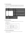
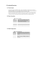
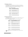
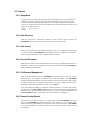
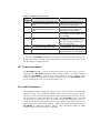
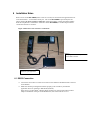
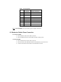
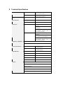
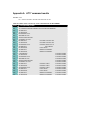
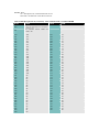
BlueBird Cellular Modem
Users’ Manual
Version 1.2
Table of Contents
1
INTRODUCTION................................................................................................................................................3
2
PRODUCT OVERVIEW ...................................................................................................................................3
2.1
2.2
2.3
2.4
3
POWER SWITCH............................................................................................................................................... 3
LIGHT EMITTING DIODES............................................................................................................................... 4
RS232 HOST INTERFACE ............................................................................................................................... 4
TRANSCEIVER AND HANDSET INPUT............................................................................................................ 4
TECHNICAL OVERVIEW ..............................................................................................................................5
3.1
FLOW CONTROL.............................................................................................................................................. 5
3.2
ERROR CORRECTION ...................................................................................................................................... 5
3.3
DATA COMPRESSION ...................................................................................................................................... 5
3.4
M ODULATION TECHNIQUES .......................................................................................................................... 6
3.5
STANDARD CONFIGURATIONS ...................................................................................................................... 6
3.6
FEATURES......................................................................................................................................................... 7
3.6.1
Sleep Mode.............................................................................................................................................7
3.6.2
Auto Power-on.......................................................................................................................................7
3.6.3
Auto Unlock............................................................................................................................................7
3.6.4
Forward Procedure..............................................................................................................................7
3.6.5
Call Process Management...................................................................................................................7
3.6.6
Remote Control Resets.........................................................................................................................7
3.6.7
Power Consumption..............................................................................................................................8
3.6.8
Audio Performance...............................................................................................................................8
3.6.9
ATI7 Command......................................................................................................................................9
4
STANDARD PACKAGE CONTENT.............................................................................................................9
5
HARDWARE AND SOFTWARE REQUIREMENTS ..............................................................................9
6
INSTALLATION NOTES ...............................................................................................................................10
6.1
6.2
RS232 CONNECTION.................................................................................................................................... 10
M ODEM -T O-CELLULAR PHONE CONNECTION .......................................................................................... 11
7
CUSTOMER SUPPORT ..................................................................................................................................12
8
TECHNICAL SPECIFICATIONS ................................................................................................................13
1 Introduction
Blue Tree Wireless Data’s BLUEBIRD Modem is a compact cellular-based modem designed to
improve the quality and reliability of data communications over the existing analog cellular
network (AMPS). Its robust features optimize data throughput (14.4Kbps), and support the
industry standard MNP10 for enhanced cellular performance.
The BLUEBIRD ruggedized construction is ideal for commercial and industrial applications such
as: sign control, point of sale terminals, data acquisition, and many more.
2 Product Overview
The BLUEBIRD is a complete 14.4 Kbps modem AND a Group III send and receive fax. It`s
operated by AT commands set, the most used standard for DTE (Data terminal Equipment)/ DCE
(Data Communication Equipment) communications. In DTE mode, the BLUEBIRD has a
maximum throughput of 57.6Kbps.
Figure 1 BLUEBIRD front view
Figure 2 BLUEBIRD back view
TRU
H/S
RESETS
1 l 2
2.1 Power Switch
The BLUEBIRD may come with an optional external switch to enable the modem (“1”) or to shut
it OFF (“0”). Versions without a power switch are always ON unless the cellular phone’s power
supply is removed.
2.2 Light Emitting Diodes
On the front plate of the modem, four red LEDs are displayed: DTR, TX, RX and CD from left to
right. There is also a multi-colored LED for power/modem status. Those five indicators offer a
user-friendly means of inquiring the modem’s operating status. They are described in the table
below.
Table 1 LED indicators
LED
Description
DTR
TX
RX
CD
PWR/STAT
G= green
R= red
O= orange
Data Terminal Ready
Transmit Data
Receive Data
Carrier Detect
Power and phone status
Color
Corresponding position
R
R
R
R
G
GF
G/RI
GF/RI
O
OF
O/RI
OF/RI
R
RF
In operation
In operation
In operation
In operation
In service
Modem in use OR handset in use
Incoming call
Relief procedure
Low Battery AND in service
Low battery AND modem in use OR handset in use
Low battery AND incoming call
Low battery AND relief procedure
Out of service OR fast busy
Locked OR no connection between cellular and modem
GF – Flashing green
RF – Flashing red
OF – Flashing orange
/RI = Ring indicator (G, R, G, R, G, R…)
2.3 RS232 Host Interface
As shown in the figure above, the BLUEBIRD is equipped with one serial host interface: a DB-9
female connector.
Figure 3 DB9 connector
2.4 Transceiver and Handset Input
On the back plate of the modem, two RJ45 connectors allow a direct connection to both the
transceiver and the handset.
3 Technical Overview
3.1 Flow Control
The modem supports two methods of flow control: XON/XOFF (or software) flow control and
RTS/CTS (or hardware) flow control. Both methods hold the flow of data between the modem and
the local DTE until the receiving equipment is ready to accept further data.
RTS/CTS is the default and preferred method of flow control. It operates by controlling the RTS
(ready to send) and CTS (clear to send) lines on the RS232 interface. To function properly, these
control lines must be connected between the modem and the DTE by an appropriate cable.
3.2 Error Correction
Table 2 Error correction
V.42
Error correction, using HDLC with 16/32
bit CRC. Also called "LAPM" (Link
Access Procedure for Modems)
MNP2-4
Microcom`s error correction protocol
MNP10
for Adverse Channel Enhancement
MNP10EC
for enhance analog cellular performance
3.3 Data Compression
Table 3 Data compression
V.42bis
Data compression, using "variable-length to
fixed-length" block coding (codeword size
constant)
MNP5
Proprietary data compression standard of
Microcom. Using "run length encoding" and
"adaptive frequency encoding" (codeword
size varies)
3.4 Modulation Techniques
The BLUEBIRD supports all the modulation protocols in the table below. The choice of the
protocol dictates the line speed of the communication. These speeds may be selected individually
via the setting of the S37 Register, but it is more commonplace to enable auto-mode to allow the
modem and remote system to determine the speed they use to talk to each other.
Table 4 Modulation Techniques
V.32bis
4800 - 14400 bps modem standard
V.32
4800 and 9600 bps modem standard
V.22bis
2400 bps modem standard
V.22
1200 bps modem standard
V.21
300 bps modem standard
Bell 212A
1200 bps modem US standard
Bell 103
300 bps modem US standard
3.5 Standard Configurations
The BLUEBIRD is configured using the “HyperTerminal” tool available by default on any PC; one
has to connect the modem directly into the COM port of the PC through a 9-pin serial cable.
Blue Tree’s standard configuration is as follows 1 :
Table 5 Blue Tree’s basic configuration of the BLUEBIRD
&F0
Restore factory configuration 0
)M1
*H1
Enable MNP10 link negotiation power
adjustment
Select MNP10 negotiation at 1200 bps
@M18
Select initial transmit level of –18 dBm
:E0
Disable the compromise equalizer
\N5
Force MNP mode
S10=150
Delay to hang-up when loss of carrier
S0=1
Auto-answer after one ring
&W0
Store the active profile in NVRAM profile 0
Note: the modem communicating with the BLUEBIRD should also be configured in the same
manner as above!
1
All commands should be preceded by “AT”.
3.6 Features
3.6.1 Sleep Mode
The Sleep Inactivity Timer of the modem (S24) sets the length of time, in seconds, that the
modem will operate in normal mode with no detected telephone line or DTE line activity
before entering low-power sleep mode. The timer is reset upon any DTE line or telephone
line activity. If the S24 value is zero, the modem will not enter sleep mode, even if there is no
DTE line or telephone activity.
Range:
0-255 seconds
Default:
0
3.6.2 Auto Power-on
When the transceiver is turned OFF, manually or due to power source variations, the
BLUEBIRD automatically reactivates it and puts it back in operating mode.
3.6.3 Auto Unlock
If the user accidentally locks the telephone (transceiver), or if it is configured in mobile mode
or auto-lock mode, the BLUEBIRD will automatically unlock the telephone to ensure that it
is able to generate and answer calls. A jumper enables this feature.
3.6.4 Forward Procedure
When the user receives a call with the handset, he can answer it by pushing the SEND key of
the handset. If the call is for the modem, the user can forward the call to the BLUEBIRD, by
using the #0* keys on his handset.
3.6.5 Call Process Management
When the DTE (equipment that the BLUEBIRD is attached to) tries to call, the cellular
network may be over capacity or interference may cause calls failures. The BLUEBIRD
recognizes these problems and in less than 2 seconds, and an auto retry feature restarts calling.
A regular modem does not recognize FAST BUSY or NO SVC signals and will wait 50
seconds (S7 register time -out) before returning “NO CARRIER”.
Also, after dialing the number, the Motorola interface generates a 5 seconds delay before
placing the call. The BLUEBIRD originates the call in 0.75 second after the last DTMF digit
has been dialed. All status of the cellular transceiver can be seen on LED “PWR/Status” of
the BLUEBIRD (NO SVC, FAST BUSY, IN USE, LOW BATT, LOCKED, etc.).
3.6.6 Remote Control Resets
The system may not answer if there is a lost DTR signal from the BLUEBIRD or any other
reason. The BLUEBIRD will automatically answer the call after 10 rings. The user at the
other end can easily send DTMF tones to generate a reset of the transceiver, the BLUEBIRD,
or any other peripherals and system connected to one of the two modem’s isolated external
reset outputs.
Table 6 Commands for remote reset
DTMF
Function
command
#1
External reset I/O # 1 'photo-MOS relay'
isolated 120mA max @ 50Vdc, Ron = 35
Ohms
#2
External reset I/O # 2 'photo-MOS relay'
isolated 120mA max @ 50Vdc, Ron = 35
Ohms
#3
Modem reset
#4
External resets I/O #1-2 and modem
reset
Characteristics
Reactivated for 2 sec each time this
command is received. Output type:
Normally open contact (N/O)
Reactivated for 2 sec each time this
command is received. Output type:
Normally open contact (N/O)
Reinitialize the modem’s chipset. The
call is dropped (modem toggles back to
on-hook state).
Activation of the 2 external resets for 2
sec then reset of the modem’s chipset.
The call is dropped (modem toggles
back to on-hook state).
#5
#*
External resets I/O #1-2 and modem
reset and cellular transceiver reset
Modem and cellular transceiver resets
Same as # 4 then power OFF and ON
of the transceiver. The call is dropped.
Same as # 3 then power OFF and ON
of the transceiver. The call is dropped.
A reset of the BLUEBIRD is automatically initiated after 90 seconds if the call fails and the
modem stays connected because the end of the call has not been detected. This feature ensures
that there will be no modem ”freezing”.
3.6.7 Power Consumption
The BLUEBIRD includes a control and supervision system of the power source, giving an
advantage to the BLUEBIRD compared to other existing solutions. The ATS24 command
enables the BLUEBIRD to initiate a sleep mode, reducing the power consumption (See
Section 8: Technical Specifications for power consumption data). The BLUEBIRD “wakes
up” if an incoming call or any activity from the DTE occurs.
3.6.8 Audio Performance
Any standard modem has a phone line interface (DAA), which converts TX and RX audio
signals on 2 wires. Also, the Motorola interface makes reverse conversion of these signals.
This process reduces the isolation between the RX and TX signals and at this time, an echo
canceling function is required and difficult to perform. The BLUEBIRD provides an isolated
TX and RX lines from end to end on the cellular network link, suppressing local echo
canceling problems of standard modems, improving the quality of data transmission and also,
reducing byte error rate and noise problems. Audio levels transmitted and received by the
BLUEBIRD are dynamically adjusted, reducing audio compression effects of AMPS
networks. These levels can be set by AT commands.
3.6.9 ATI7 Command
With the ATI7 command, the BLUEBIRD sends back information about the receiving level
and the transceiver status (NO SVC, LOW BATT, LOCK, IN USE, FAST BUSY). See
appendix A.
4 Standard Package Content
The standard BLUEBIRD package contains the following components:
??
??
??
??
1 BlueBird modem (by BlueTree Wireless Data)
1 RJ45 cable (for the Motorola 3 watts) or 1 SKN4291B cable (for the Motorola DPC)
1 DC adaptor (for the Motorola DPC)
1 user manual
Accessories for a fully customized product may be purchased from Blue Tree Wireless Data Inc.
5 Hardware and Software Requirements
To have a fully operational mo dem, the installer must provide the following:
?? A Motorola transceiver: either a DPC 0.6-watt, or a 3-watt cellular telephone (depending upon
which version of modem)
?? An activation of the above transceiver on the cellular network
?? An MNP10 compatible modem on the PC (host) to communicate with the BlueBird modem
(We have tested and recommend the 56k BOCA Tidalwave external modem)
6 Installation Notes
Both versions of the BLUEBIRD (either 3-watt or 0.6-watt) are connected to the application device
in the same manner – via the RS232 serial port. The 3-watt BLUEBIRD is powered by the cell
phone, meaning no power supply is required to operate the modem. It draws the needed 100mA
from the cell phone it is connected to. With the 0.6-watt BLUEBIRD, a 12VDC adaptor must be
connected to the DC-in connector.
Figure 4 Motorola 3-watt transceiver connections
You plug the modem directly to the
handset RJ45 connector
RS232 for your application.
6.1 RS232 Connection
?? Connect the device that is to send./receive data via the modem to the DB-9 female connector
on the modem.
?? Make sure that the pin designation matches properly (refer to Table 6), and that the
application device is operating in DTE mode (terminal).
If the device is in DCE mode, a DCE-to-DCE connection is required: add a DCE-to-DCE
adapter to the RS232 serial port of the BlueBird1.0, then connect the device to it.
Table 7 PIN designation
PIN #
DB-9 female DB-9 male after DCEon modem
to-DCE connection
1
DCD
DCD
2
TXD
RXD
3
4
5
RXD
DTR
GND
TXD
DSR
GND
6
7
8
DSR
CTS
RTS
DTR
RTS
CTS
9
RI
RI
Note: the BLUEBIRD does not provide any power supply to the device.
6.2 Modem-to-Cellular Phone Connection
0.6-watt BLUEBIRD:
?? Insert the RJ45 cable into the TRU connector
?? Insert the SKN4192 cable into the Motorola DPC cellular phone
3-watt BLUEBIRD:
?? Insert the RJ45 cable into the TRU connector
?? Insert the other side of that RJ45 cable into the Motorola 3-watt transceiver
?? Connect the handset to the modem via the RJ45 H/S connector.
7 Customer Support
For customer/technical support please contact us at:
BlueTree Wireless Data Inc.
175 Montpellier Blvd.
St. Laurent, QC
Canada
Phone: 1-800-463-6945
8 Technical Specifications
Dimensions (L x W x H)
BLUEBIRD (0.6-watt)
Weight
230g (8oz)
134mm x 13mm x 38mm
(5.25” x 5.10’’ x 1.50’’)
114mm x 83mm x 32mm
(4.50” x 3.25’’ x 1.25’’)
230g (8oz)
Environmental
Operating Temperature
–25 to 70 C (-13 to 144 F)
Relative Humidity
0 to 95% non-condensing
BLUEBIRD (0.6-watt)
1 Standard RS-232, 9-pin serial
connector
1 RJ45 connectors for Motorola DPC
Transceiver
1 MTA100, 4-pin connector, for 2
opto-isolated external resets (30
BLUEBIRD (3-watt)
Connectors
VAC/VDC @ 100mA max.)
BLUEBIRD (3-watt)
1 Standard RS-232, 9-pin serial
connector
2 RJ45 connectors for Motorola 3
watts Transceiver and handset
1 MTA100, 4-pin connector, for 2
opto-isolated external resets (30
VAC/VDC @ 100mA max.)
Regulatory compliance
FCC part 15, class B
D.O.C. certified
Power Requirements
Working mode
Transmit data
Needs less than 100mA. (supplied by
the cellular phone)
Needs less than 30mA. (supplied by
the cellular phone)
TX
Receive data
RX
Data terminal ready
DTR
Carrier detect
CD
Power and phone status
PWR/STAT
Sleep mode
LED Indicators
General
MNP10 for enhanced analog performance
14.4 Kbps
Shut off protection
Remote hard reset
2 external resets for peripherals
Appendix A AT17 command results
Format: Sxxx
xxx = Status returned in decimal code from 000 to 027
Table 8 Cellular status returned by ATI7 command from the BLUEBIRD
Sxxx
Corresponding status
000
001
002
003
004
005
006
007
008
009
010
011
012
013
014
015
016
017
018
019
020
021
022
023
024
025
026
027
CONVERSION ERROR
NO CONNECTION BETWEEN CELLULAR AND MODEM
IN SERVICE
NO SERVICE
INCOMING CALL
MODEM IN USE
RELIEF PROCEDURE
HANDSET IN USE
IN SERVICE
LOCKED CELLULAR
NO SERVICE
LOCKED CELLULAR
INCOMING CALL
LOCKED CELLULA R
IN SERVICE
FAST BUSY
NO SERVICE
FAST BUSY
IN SERVICE
REDIAL HANDSET
NO SERVICE
REDIAL HANDSET
I IN SERVICE
LOW BATTERY
NO SERVICE
LOW BATTERY
INCOMING CALL
LOW BATTERY
MODEM IN USE
LOW BATTERY
RELIEF PROCEDURE
LOW BATTERY
HANDSET IN USE
LOW BATTERY
IN SERVICE
LOCKED CELL.
LOW BATTERY
NO SERVICE
LOCKED CELL.
LOW BATTERY
INCOMING CALL
LOCKED CELL.
LOW BATTERY
IN SERVICE
FAST BUSY
LOW BATTERY
NO SERVICE
FAST BUSY
LOW BATTERY
IN SERVICE
REDIAL HANDSET
LOW BATTERY
NO SERVICE
REDIAL HANDSET
LOW BATTERY
Format: Rxxx
xxx = Reception level in decimal from 000 to 255
This table is for Motorola 3-watt EE3 transceiver.
Table 9 RSSI (Reception level) returned by ATI7 command of the 3-watt BLUEBIRD
Rxxx
Dbm
000
Locked cell, RSSI reading error or incompatible
transmitter = 000
001
No connection between cellular and
modem = 001
050
051
052
053
054
055
056
057
058
059
060
061
062
063
064
065
066
067
068
069
070
071
072
073
074
075
076
077
078
079
080
081
082
083
084
085
086
087
088
089
090
-120
-119
-118
-117
-116
-115
-114
-113
-112
-111
-110
-109
-108
-107
-106
-105
-104
-103
-102
-101
-100
-99
-98
-97
-96
-95
-94
-93
-92
-91
-90
-89
-88
-87
-86
-85
-84
-83
-82
-81
-80
Rxxx
Dbm
091
092
093
094
095
096
097
098
099
100
101
102
103
104
105
106
107
108
109
110
111
112
113
114
115
116
117
118
119
120
121
122
123
124
125
126
127
128
129
130
-79
-78
-77
-76
-75
-74
-73
-72
-71
-70
-69
-68
-67
-66
-65
-64
-63
-62
-61
-60
-59
-58
-57
-56
-55
-54
-53
-52
-51
-50
-49
-48
-47
-46
-45
-44
-43
-42
-41
-40