1
User Manual for the
HE500OCS050 &
HE500OCS051
Operator Control Station
Third Edition
01 September 1998
MAN0022-03
PREFACE
01 SEPTEMBER 1998
PAGE 2
PREFACE
This manual explains how to use the Horner Electric HE500OCS050 and HE500OCS051.
Copyright (C) 1998 Horner Electric, Inc., 640 North Sherman Drive Indianapolis, Indiana 46201. All rights
reserved. No part of this publication may be reproduced, transmitted, transcribed, stored in a retrieval
system, or translated into any language or computer language, in any form by any means, electronic,
mechanical, magnetic, optical, chemical, manual or otherwise, without the prior agreement and written
permission of Horner Electric, Inc.
All software described in this document or media is also copyrighted material subject to the terms and
conditions of the Horner Software License Agreement.
Information in this document is subject to change without notice and does not represent a commitment on
the part of Horner Electric, Inc.
Cscape is a trademark of Horner Electric, Inc.
CsCAN is a trademark of Horner Electric, Inc.
DeviceNet is a trademark of the Open DeviceNet Vendor Association, Inc.
For user manual updates, contact Horner Electric Advanced Products
Group, Technical Support Division, at (317) 916-4274 or visit our
website at www.heapg.com.
HE500OCS050/051 User Manual
PAGE 3
01 SEPTEMBER 1998
PREFACE
LIMITED WARRANTY AND LIMITATION OF LIABILITY
Horner Electric, Inc. ("HE") warrants to the original purchaser that Operator Control Station manufactured
by HE are free from defects in material and workmanship under normal use and service. The obligation
of HE under this warranty shall be limited to the repair or exchange of any part or parts which may prove
defective under normal use and service within two (2) years from the date of manufacture or eighteen
(18) months from the date of installation by the original purchaser whichever occurs first, such defect to
be disclosed to the satisfaction of HE after examination by HE of the allegedly defective part or parts.
THIS WARRANTY IS EXPRESSLY IN LIEU OF ALL OTHER WARRANTIES EXPRESSED OR IMPLIED
INCLUDING THE WARRANTIES OF MERCHANTABILITY AND FITNESS FOR USE AND OF ALL
OTHER OBLIGATIONS OR LIABILITIES AND HE NEITHER ASSUMES, NOR AUTHORIZES ANY
OTHER PERSON TO ASSUME FOR HE, ANY OTHER LIABILITY IN CONNECTION WITH THE SALE
OF THIS THIS WARRANTY SHALL NOT APPLY TO THIS OR ANY PART THEREOF WHICH HAS
BEEN SUBJECT TO ACCIDENT, NEGLIGENCE, ALTERATION, ABUSE, OR MISUSE. HE MAKES NO
WARRANTY WHATSOEVER IN RESPECT TO ACCESSORIES OR PARTS NOT SUPPLIED BY HE.
THE TERM "ORIGINAL PURCHASER", AS USED IN THIS WARRANTY, SHALL BE DEEMED TO
MEAN THAT PERSON FOR WHOM THE ARE ORIGINALLY INSTALLED. THIS WARRANTY SHALL
APPLY ONLY WITHIN THE BOUNDARIES OF THE CONTINENTAL UNITED STATES.
In no event, whether as a result of breach of contract, warranty, tort (including negligence) or otherwise,
shall HE or its suppliers be liable of any special, consequential, incidental or penal damages including,
but not limited to, loss of profit or revenues, loss of use of the products or any associated equipment,
damage to associated equipment, cost of capital, cost of substitute products, facilities, services or
replacement power, down time costs, or claims of original purchaser's customers for such damages.
To obtain warranty service, return the product to your distributor with a description of the
problem, proof of purchase, post paid, insured and in a suitable package.
ABOUT PROGRAMMING EXAMPLES
Any example programs and program segments in this manual or provided on accompanying diskettes are
included solely for illustrative purposes. Due to the many variables and requirements associated with any
particular installation, Horner Electric cannot assume responsibility or liability for actual use based on the
examples and diagrams. It is the sole responsibility of the system designer utilizing the HE500OCS050
and HE500OCS051to appropriately design the end system, to appropriately integrate the HE500OCS050
and HE500OCS051and to make safety provisions for the end equipment as is usual and customary in
industrial applications as defined in any codes or standards which apply.
Note:
The programming examples shown in this manual are for
illustrative purposes only. Proper machine operation is the sole
responsibility of the system integrator.
HE500OCS050/051 User Manual
PREFACE
01 SEPTEMBER 1998
PAGE 4
TABLE OF CONTENTS
PREFACE................................................................................................................................................2
LIMITED WARRANTY AND LIMITATION OF LIABILITY ..........................................................................3
ABOUT PROGRAMMING EXAMPLES ....................................................................................................3
TABLE OF CONTENTS ...........................................................................................................................4
SAFETY NOTICE FOR THE HEOCS050/51 ............................................................................................5
CHAPTER 1: INTRODUCTION ...............................................................................................................6
1.1
Product Description................................................................................................................... 6
1.2
Cscape Software Package Option .......................................................................................... 6
CHAPTER 2: INSTALLATIONS...............................................................................................................8
2.1
Connections.............................................................................................................................. 8
2.1.1
General.............................................................................................................................. 8
2.1.2
Primary Power Port ............................................................................................................ 8
2.1.3
CAN Port ........................................................................................................................... 9
2.1.4
RS-232 Port ......................................................................................................................10
2.1.5
8 Positive (or Negative) to Isolated Common Inputs (Input Port) .......................................11
2.1.6
8 Sinking to Isolated Common Outputs..............................................................................12
2.2
Mounting Requirements ...........................................................................................................13
2.3
Placing the OCS into Service ...................................................................................................14
2.4
Status Indicators ......................................................................................................................15
2.5
Operation.................................................................................................................................16
2.6
User Screens ...........................................................................................................................16
CHAPTER 3: CONFIGURATION ..........................................................................................................18
3.1
General....................................................................................................................................18
3.2
Entering the Configuration Menu ..............................................................................................18
3.3
Menu Options...........................................................................................................................18
HE500OCS050/051 User Manual
PAGE 5
01 SEPTEMBER 1998
PREFACE
Important Safety Notice
SAFETY NOTICE FOR THE HEOCS050/51
This product is NOT to be used in applications where critical control is done
based on Network inputs to the unit. The integrity of the data being sent to the
unit is uncertain in the first 1-10 scans of the unit. These units are primarily
designed for the simple, non-safety-related control and data acquisition.
HE500OCS050/051 User Manual
CHAPTER 1: INTRODUCTION
01 SEPTEMBER 1998
PAGE 6
CHAPTER 1: INTRODUCTION
1.1
Product Description
The Horner Electric Operator Control Station (HE500OCS050 or HE500OCS051) combines the
power of a Horner Electric OIU057 (small Operator Interface Unit) with on-board I/O capability
and networking within one controller.
Powerful and compact, the controller has Serial and CAN (Controller Area Network)
communication abilities. The unit contains a standard 9-pin RS-232 for programming/debugging,
monitoring and network administration from an IBM-compatible PC. The HE500OCS050 uses
Horner Electric’s CsCAN (pronounced “Sea-scan”) peer to peer networking. The HE500OCS051
works as a DeviceNet slave. When several Operator Control Stations are networked together
to achieve a specific purpose, the system performs like a “large parallel-processing PLC”.
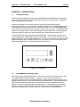
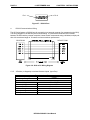
The Operator Control Station has several desirable features. The front panel contains a 2x16
Liquid Crystal Display (with backlight), which is highly visible. The front panel also has five userprogrammable keys, an UP key and a DOWN key. The bottom of the unit has two Horner Electric
Micro I/O interface ports (for 8 inputs and 8 outputs), DC power port, serial communication and
CAN communication ports. The controller measures 3.5”x6”x5”x6.”
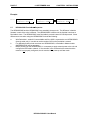
F1
F2
F3
F4
F5
ENTER
Figure 1.1 – Front View
1.2
Cscape Software Package Option
As an option, Horner Electric offers Cscape (pronounced “Sea-scape”) Software for use with
the HE500OCS050 and HE500OCS051 . Powerful yet easy-to-use, the ladder editor
programming software allows for the off-line creation, editing, saving and loading of ladder logic
programs and text screens for the HE500OCS050 and HE500OCS051. When connected to the
serial port of the Operator Control Station, the software user has the capability to download,
upload, run and monitor ladder programs and text screens. A comprehensive documentation
package is included with the purchase of Cscape Software and contains software, manuals,
and a communication cable. The part number for Cscape Software is HE500OSW232.
HE500OCS050/051 User Manual
PAGE 7
01 SEPTEMBER 1998
CHAPTER 1: INTRODUCTION
Table 1.1 – Specifications
General
Processing Speed
75,000 ladder elements per second
Operating Temperature
0° to 60° C
Humidity
5% to 95% non-condensing
NEMA Rating
NEMA 4-12
DC Power Source
Primary Power Range
9 - 32 VDC
Typical Power Draw
80mA@24VDC
Inrush Current
700mA@24VDC for 7mS
CAN Power Range
12 - 30 VDC
CAN Power Current
75mA maximum
Dimensions
Height
3.50" (89mm)
Width
6.00" (153mm)
Mounting Depth
5.60" (142mm)
Internal Functions
Output Coils
8
Internal Coils
48
Timers/Counters
16
Network Inputs
16
Network Outputs
16
Text Screens
50
User Keys
5
Communications
Serial
Standard 9 pin RS-232 for
programming, monitoring, and network
administration from a IBM compatible
PC
CAN
HE500OCS050 CsCAN peer to peer
networking
HE500OCS051 DeviceNet Slave (16
polled input, 16 polled outputs)
Input / Output
2 Horner Electric Micro I/O interface
ports
Keypad
5 user programmable keys + UP,
DOWN and ENTER
Display
2 x 16 Back-lit Liquid Crystal with 0.375"
characters
Noise Specifications
IEC Rating
IEC 1000-4-2, Severity Level 3
(performance criteria B for ESD Air
Discharge) & Severity Level 2
(performance criteria A for ESD Direct
Contact Discharge).
IEC 1000-4-4, Severity Level 3
(performance criteria B for FTB on
Power Lines) & Severity Level 3
(performance criteria A for FTB on I/O
Lines).
HE500OCS050/051 User Manual
CHAPTER 2: INSTALLATIONS
01 SEPTEMBER 1998
PAGE 8
CHAPTER 2: INSTALLATIONS
2.1
Connections
2.1.1
General
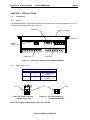
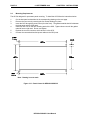
The HE500OCS050/051 connectors are located on the bottom of the module as depicted in Figure 2.1.
The following sections describe each connector.
Serial Port
Front Panel
CAN Port
Primary
Power
Output Port
Input Port
Figure 2.1 – Connectors, Bottom View of HE500OCS050/051
2.1.2
Primary Power Port
Table 2.1 – Primary Power Port Pins
Pin
Signal
Description
1
V+
Input power supply
voltage
2
VInput power supply
ground
Pin 2
Figure 2.2 Power Connector
(Primary Power Port)
Pin 1
Figure 2.3
Pin 2
As viewed looking at
the HE500OCS050/051
Note: Power Supply Voltage Range is from 9-32 volts DC.
HE500OCS050/051 User Manual
PAGE 9
2.1.3
01 SEPTEMBER 1998
CHAPTER 2: INSTALLATIONS
CAN Port
Pin
1
2
3
4
5
Table 2.2 – CAN Port Pinsc
Signal
Description
V+
CAN Power +
C+
CAN High
Shield
Shield
CCAN Low
GND
CAN Power Ground
Pin 5
VCS hield
C+
Pin 1
V+
Figure 2.4 – Network Connector
(CAN Port)
a.
Figure 2.5 – As viewed looking
at the HE500OCS050/051
CAN Wiring Rules (See Figure 2.6.)
1.
A CAN network should be wired in a daisy-chained fashion such that there are exactly two
physical end-points on the network.
2.
The two nodes at the physical end-points should have 121 ohm 1% terminating resistors
connected across the CN_L and CN_H terminals.
3.
The data conductors (CN_L and CN_H) should be a 24 AWG shielded twisted pair for “thin cable”
and 22 AWG shielded twisted pair for “thick cable”, with 120 ohm characteristic impedance. Horner
Electric recommends using a Belden wire #3084A (“thin”) for typical industrial environments and a
#3082A (“thick”) for environments where noise is a concern.
4.
The power conductors (V- and V+) should be an 18 AWG twisted pair for “thin cable” and a 15
AWG twisted pair for “thick cable.”
5.
The V- power conductor should be connected to a good earth ground at one place only on the
network, preferably at one the two physical endpoints.
6.
Notice that for a section of cable between two nodes, the cable shield is connected to the cable
shield input at one end of the cable only.
7.
A CAN network (without repeaters) should be limited to 64 nodes (with 63 cable segments) with a
maximum cable length of 1500 ft.
8.
Up to four CAN network segments, which adhere to the above rules, may be connected together
using three CAN repeaters (HE200CGM100). In this manner, a CAN network may be extended to 253
nodes with a total cable distance of 6000 ft.
HE500OCS050/051 User Manual
VCN _L
SH IEL D
CN _H
V+
PAGE 10
VCN _L
SH IEL D
CN _H
V+
01 SEPTEMBER 1998
VCN _L
SH IEL D
CN _H
V+
VCN _L
SH IEL D
CN _H
V+
CHAPTER 2: INSTALLATIONS
S H IE LD
S H IE LD
Figure 2.6 – CAN Port Wiring Diagram
2.1.4
RS-232 Port
Pin
1
2
3
4
5
6
7
8
9
Table 2.3 – RS-232 Port Pins
Signal
Description
DCD
Always high
TXD
Transmitted Data
RXD
Received Data
DTR
Ignored
GND
Ground
DSR
Always high
CTS
Clear to Send
RTS
Request to Send
RI
Always high
HE500OCS050/051 User Manual
Direction
Out
Out
In
Out
In
Out
Out
CN_H
V+
VC N _L
SH IE L D
120Ω
WHT
RED
BLK
BLU
W HT
RE D
BL K
BLU
BLK
BLU
W HT
RE D
VC N _L
SH IE L D
CN_H
V+
CN_H
V+
120Ω
VC N _L
SH IE L D
CN_H
V+
SH IE L D
12 0 Ω
WHT
RED
S H IE L D
BL K
BLU
VC N _L
120Ω
PAGE 11
01 SEPTEMBER 1998
Pin 1
CHAPTER 2: INSTALLATIONS
Pin 9
Figure 2.7 – RS-232 Port
a.
RS-232 Communications Wiring
The OCS units feature an RS-232 port for connection to a personal computer (for programming the OCS).
The wiring diagram for the RS-232 ports is shown below. If a permanent connection is to be made
between the OCS and the personal computer, Horner Electric recommends using a shielded, multiple pair
wire with a maximum length of 15 meters to ensure maximum performance.
9-PIN PC COM
OCS RS-232
Figure 2.8 - OCS to PC Wiring Diagram
2.1.5
8 Positive (or Negative) to Isolated Common Inputs (Input Port)
Table 2.4 - Input Port
Rated Voltage
Input Voltage Range
Input Characteristics
On-state Voltage
Off-state Voltage
On-state Current
Off-state Current
On response Time
Off response Time
± 24VDC
–30 to +30VDC
± 15 to ± 30VDC
–6 to +6VDC
± 4.5mA minimum
± 2.0mA maximum
2ms maximum
2ms maximum
HE500OCS050/051 User Manual
CHAPTER 2: INSTALLATIONS
01 SEPTEMBER 1998
PAGE 12
9 8 7 6 5 4 3 2 1
Input x
Polarity may
be reversed.
Input y
9 = Common
1 to 8 = Inputs 1 to 8
C om m on
Figure 2.9 – Input Port (As viewed
looking at the HE500OCS050/051)
2.1.6
-
+
Figure 2.10 – Input Port Wiring Diagram
8 Sinking to Isolated Common Outputs
Table 2.5 – Output Port
Rated Voltage
± 24VDC
Output Voltage Range
± 6 to ± 25VDC
Output Current
±0.5A continuous per point
Output Characteristics
0.3V@100mA
0.5V@400mA
On Output Voltage
0.7V@700mA
On response Time
1ms maximum
Off response Time
1ms maximum
Current Limit
1A typical
Inductive clamp diode to isolated
Protection
supply thermal shutdown
10 9 8 7 6 5 4 3 2 1
O u tpu t x
L oa d
O u tpu t y
L oa d
C om m on
9 = Output Common (-)
10 = Isolated output power (+)
1 to 8 = Outputs 1 to 8
-
+
Polarity may
be reversed.
P ow er
Figure 2.11 - Output Port (As viewed
looking at the HE500OCS050/051
Figure 2.12 – Output Port Wiring Diagram
HE500OCS050/051 User Manual
PAGE 13
2.2
01 SEPTEMBER 1998
CHAPTER 2: INSTALLATIONS
Mounting Requirements
The OCS is designed for permanent panel mounting. To install the OCS follow the instructions below:
1.
2.
3.
4.
5.
6.
Cut the host panel as described in the corresponding drawing on the next page.
Remove the rear cover by removing the four screws holding it in place.
Insert the OCS through the panel cutout (from the front). The gasket material should lie between
the host panel and the OCS panel.
Install four hex nuts on the four mounting studs of the OCS. Tighten these nuts until the gasket
material forms a tight seal. Do not over-tighten.
Replace the rear cover screws, which secure it to the OCS.
Connect the communications and power cables to the OCS ports.
Note: Drawing is not to scale.
Figure 2.13 – Panel Cutout for HE500OCS050/051
HE500OCS050/051 User Manual
CHAPTER 2: INSTALLATIONS
2.3
01 SEPTEMBER 1998
PAGE 14
Placing the OCS into Service
Although the Operator Control Stations have been designed for use in industrial environments, the
installation of the unit has an impact on its immunity to noise. A number of considerations must be made
when placing the OCS into service to ensure years of reliable operation. A listing of some of the
considerations follows:
a.
Secure Physical Mounting
The OCS should be securely mounted, isolated from severe vibration.
b.
Ground the OCS Chassis
The OCS chassis needs to be connected to a good earth ground. Make the connection to one of the four
mounting studs on the unit. The studs provide a direct connection to the OCS chassis to which all OCS
printed circuit board earth ground connections are made. With the OCS chassis grounded, electrical
noise can generally be shunted effectively to earth ground.
c.
Install the OCS Rear Cover
The steel rear cover provides important protection against RF (radio frequency) interference.
d.
Use a Properly Constructed Communications Cable
Great care should be made in the construction of the communications cable connecting the OCS to the
target device.
e.
Ground the Communications Cable Shield
Ensure the proper grounding of the communications cable shield. Without proper shield grounding, the
shield typically acts like an antenna and increases the amount of noise induced upon the cable.
f.
Route Communications Cable Properly
Make sure that the communications cable is routed away from high voltage wiring. Communications
cable need to be routed in conduit or a wire-way containing only communications or low energy signals.
Be careful to avoid routing cable around traditionally noisy electrical components such as motor starters,
solenoids, drives, inverters, etc. These components can inductively couple electrical noise onto the
communications wiring.
g.
Route Power Wiring Properly
When using the OCS with 9-32VDC power, route the OCS power conductors away from noise inducing
electrical components and wiring.
HE500OCS050/051 User Manual
PAGE 15
2.4
01 SEPTEMBER 1998
CHAPTER 2: INSTALLATIONS
Status Indicators
The operator is notified of the following states by a flashing character in the upper right corner of the
display:
a.
The unit fails one of its self-tests.
b.
The unit is placed in idle mode.
c.
The unit is in firmware update mode.
d.
The unit is in DO/IO mode.
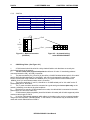
Status Indicator Character
F1
F2
F3
F4
F5
ENTER
Figure 2.14 – Status Indicator Character
When the unit is placed in idle mode, the flashing character looks like the following:
When the unit has detected an error while performing a self-test, it displays this character. (The unit has
been forced into idle mode as well):
When the unit is in DO/IO mode, the inputs are read, and outputs are written, but no ladder program
operations are performed.
When the serial port is in firmware update mode, the serial port is not available to connect to the ladder
editor. In this case, the following character is displayed:
HE500OCS050/051 User Manual
CHAPTER 2: INSTALLATIONS
2.5
01 SEPTEMBER 1998
PAGE 16
Operation
When the OCS050 unit first powers-up, it displays "Horner Electric OCS: HE500OCS050". This
message then fades and the first user screen will be displayed.
After the OCS displays this message, the unit will perform tests to see the current state of the network.
Three different scenarios may occur. Each of them is described below.
Scenario #1: No power is supplied to the CAN port. The networking is turned OFF, the unit is placed in
idle mode, and an error message is displayed on the screen for 1 second. When checking "Diagnostics"
with Cscape, the Network Operations will display ERRORS.
Scenario #2: If there is power connected to the CAN port, and no other units are on the CAN network (or
this is the first device to power-up on the network), the message "Waiting for Net: F1 = Disable Net" is
shown. If another device is placed on the CAN network, the message clears and operation continues. If
F1 is pressed, network is disabled and operation continues. (The PLC and interface portions continue to
operate).
Scenario #3: If a unit powers-up and finds another unit with the same node number as itself, the display
shows "Duplicate ID Network Disabled". The network is disabled, the network OK system bit (%S2) is
cleared and is displayed on the editor (diagnostics screen) as "Network Conflicts: Failed".
Note: The ID checking works when one of two devices with the same ID is powered-up more than 1
second before the other. If both devices are powered-up at the same time, this method of
ID checking may not work.
At any time, the OCS unit can be reset by pressing:
2.6
+
F1
+
F2
.
User Screens
In normal operating mode there are a set of user-defined screens that can be scrolled through using the
and keys.
If the ladder program energizes a text coil, the screen associated with this coil is displayed, overriding the
"normal" user screens. This is designed to show alarm conditions. When the text coil is de-energized,
the previous screen that was being viewed before the alarm is returned.
Note: If the user was in the middle of editing a set point, the edit will continue once the alarm screen
clears.
If the screen contains a set point, the user can press the Enter key to enter the edit mode.
When in edit mode, a cursor will appear on one digit of the editable number. Use the F1 key to move to
the digit to the left and the F2 key to move to the digit to the right. Use and keys to increment or
decrement the digit.
If there is more than one field on the screen, select a field by pressing F1 or F2 and edit as needed.
As a result of pressing the F1 or F2 keys, the value chosen may exceed the minimum or maximum set
by the user program. If the value is outside of these minimum or maximum points, the value will not
change.
Pressing Enter will exit the edit mode and return to the "normal" user screen mode.
HE500OCS050/051 User Manual
PAGE 17
01 SEPTEMBER 1998
CHAPTER 2: INSTALLATIONS
Example:
Enter
2.7
Sheep count
setpoint: 00020
F1
Sheep count
setpoint: 00020
Sheep count
setpoint: 00030
Enter
HE500OCS051 DeviceNet Properties
The HE500OCS050 and the HE500OCS051 are essentially the same unit. The difference is that the
firmware in each of the units is different. The HE500OCS051 is different in the fact that it works as a
DeviceNet slave. The HE500OCS051 uses DeviceNet protocol instead of CSCAN protocol. Some
differences to note when using the HE500OCS051 include the following:
a.
b.
c.
With DeviceNet, nodes 0-63 are available and if the OCS is connected to one HE500OCS051
(through serial port), it is unable to monitor another OCS on the DeviceNet network.
For applications that include more than one HE500OCS051, a DeviceNet Master module
(#HE693DNT250) will be necessary.
Before powering-up the HE500OCS051, it is necessary to apply network power to the unit and
configure the DeviceNet network. If the controller is not connected to the network and the
network is not properly configured, the unit remains in the power-up self-test mode.
HE500OCS050/051 User Manual
CHAPTER 3: CONFIGURATION
01 SEPTEMBER 1998
PAGE 18
CHAPTER 3: CONFIGURATION
3.1
General
The OCS can be easily configured. The following sections describe the parameters and procedures used
to configure the OCS. The sections describe the on-board configuration of the unit.
3.2
Entering the Configuration Menu
1.
To enter the configuration menu, press the
2.
The Configuration Mode looks like the following:
key and the
key at the same time.
Î Network ID
Set Contrast
3.
Pressing the Enter key selects the option that the indicator arrow is pointed to. Pressing
allows the user to scroll up or down through the menu options as described in Section 3.3.
3.3
or
Menu Options
There are eight different menu options: The options include (a) View OCS Info (b) View Registers, (c)
View I/O Slots, (d) View Char Set, (e) Set Fkeys Mode, (f) Set RS232 Mode (g) Set Network ID and
(h) Set Contrast.
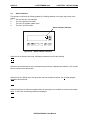
a.
View OCS Info
OCS Information Screen
OCS Mode: Run
Scan-rate: 0.0
Mem Used: 370
Firmware: 1.5
Self-Test:
OK
Fault Code:
0
%I Filter:
0
Net Update:
0
………………………………………………………………………………………………………………………………………………………………………………………………………………………..
What the screen display looks like θ
The OCS Info screen shows information about the internal state of the unit. Pressing
through the different items. Pressing Esc will return to the Main Menu.
Represents bottom
of screen
and
scrolls
Parameter
Description
Firmware
OCS Mode
%I Filter
Shows the execution engine firmware version.
Shows the scanning mode (Idle, DO/IO, and Run).
Shows the number of scans a physical input must be stable before its state is
accepted. A zero shows filtering is turned off.
Shows the 100's of milliseconds before the network data is broadcast. This
broadcast is in additional to change of state broadcast. A zero shows this feature
is disabled.
Shows the number of bytes used by the ladder program.
Shows the number of milliseconds for the scan before this screen was displayed.
Shows if the power-up self-test passed or failed.
Shows the 8-bit fault code number in hexadecimal. (See Table 3.1.) If more than
one fault is detected, the displayed code will be the hexadecimal sum of the
Net Update
Mem Used
Scan-Rate
Self-Test
Fault Code
HE500OCS050/051 User Manual
PAGE 19
01 SEPTEMBER 1998
CHAPTER 3: CONFIGURATION
fault codes.
Code
01
02
04
08
10
20
40
80
Table 3.1 – Fault Codes
Description
Bios checksum error
Firmware checksum error
User program checksum error
RAM test failed
Duplicate network ID error
Invalid network ID error
I/O configuration error
Network not usable error
Net Update
Global data is sent every time it's state changes. If it has not been sent in the time defined by the network
update time-out, it is sent at that time. The network time-out is the maximum time that can elapse without
broadcasting network data. If the data changes every scan this is the minimum time that can elapse
before data is transmitted. If the time-out is set to zero, the data is sent only on change of state.
b.
View Registers
What the screen display looks like θ
I1:
Q1:
01010101
00011100
The View Registers screen allows the user to view the state of internal PLC registers. Using the and
keys, the different data types can be displayed. The data types include Inputs (I), Outputs (Q),
Temporary (T), Global Network Inputs (IG), Global Network Outputs (QG), Timers and Counters (TC),
Key Bits (K) and System (S). Pressing Esc will return to the configuration menu.
c.
View I/O Slots
What the screen display looks like θ
1: 8I 8Q 24VDC
K: Keypad (8)
The View I/O Slots screen allows the I/O device on the unit to be displayed. Using the and keys,
position the arrow next to the item to configure. Press ESC to return to the configuration menu.
d.
View Char Set
What the screen display looks like θ
Press Enter, then use the and
return to the configuration menu.
Use ↑↓ to view
Next char:
8=↓
keys to scroll through the character set. Press Enter, then Esc to
HE500OCS050/051 User Manual
CHAPTER 3: CONFIGURATION
e.
01 SEPTEMBER 1998
PAGE 20
Set FKeys Mode
The user keys on the keypad can be configured to operate in one of two ways. When a user key is
pressed it can TOGGLE the point associated with the key or it can MOMENTARILY turn the point ON
when the key is pressed. Make a selection by pressing Enter, then use the and keys. Press Enter
once your selection has been made.
Note: If the selection has been changed, the unit will stop executing the ladder code for up to 10
milliseconds while the key state is saved in non-volatile memory.
f.
Set RS232 Mode
What the screen display looks like θ
Use ↑↓ to change
RS232 md: CSCAN
The Set RS-232 Mode screen allows the mode of the serial port to be set. Press Enter, then use the
and keys to toggle between the options. Press the Enter key to save the option. The CSCAN mode
allows Cscape to connect to the serial port for uploads, downloads, monitoring and control. The
Firmware Update mode allows a Horner Electric (APG) firmware update and configuration utility to be
used. Pressing Enter will save the selected mode. The firmware is ready to download when a solid “U”
is displayed.
Note: If the port setting is changed, the unit will stop executing the ladder code for up to 10 milliseconds
while the setting is saved in non-volatile memory.
g.
Set Network ID
What the screen display looks like: θ
Network OK?
Network ID:
Yes
37
In the Set Network ID screen, the user is able to set the Network ID number. Each unit should have a
unique ID number for the network. Press Enter to select “Network ID.” Use and to increment or
decrement the digit under the cursor. If the node number does not need to be changed, press Enter and
the unit will go back to displaying the menu screen. If you want to save the change to the node number,
press Enter.
Note: The node number will be saved and the unit stops executing for one second while a series of
network checks are performed with the new network ID.
h.
Set Contrast
What the screen display looks like θ
Use ↑↓ to adjust
contrast: ∈∈∈∈∈∈
The Contrast screen allows the contrast of the LCD display to be adjusted. By pressing the key, the
display gets darker, and the numbers increment. By pressing the key, the display gets lighter, and the
numbers decrement. Once the desired contrast is selected, press the Enter key and Esc to return to the
configuration menu.
Note: If the contrast setting is changed, the unit stops executing the ladder code for up to 10 milliseconds
while the setting is saved in non-volatile memory.
HE500OCS050/051 User Manual
PAGE 21
01 SEPTEMBER 1998
CHAPTER 3: CONFIGURATION
HE500OCS050/051 User Manual