1
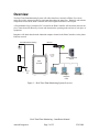
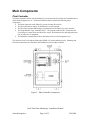
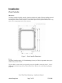
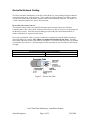
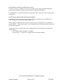
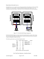
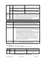
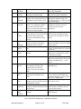
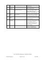
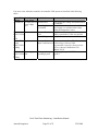
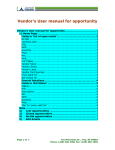
Real-Time Plant Monitoring Installation Manual WARNINGS ............................................................................................................................................... 2 OVERVIEW ............................................................................................................................................... 3 MAIN COMPONENTS............................................................................................................................. 4 Plant Controller ........................................................................................................................................4 DeviceNet Network Cabling ....................................................................................................................5 Photo-eye Sensors ....................................................................................................................................6 DeviceNet Hubs .......................................................................................................................................6 INSTALLATION....................................................................................................................................... 7 Plant Controller ........................................................................................................................................7 DeviceNet Network Cabling ....................................................................................................................9 Photo-Eye Sensors..................................................................................................................................12 DeviceNet Hubs .....................................................................................................................................15 TROUBLESHOOTING .......................................................................................................................... 19 General ...................................................................................................................................................19 DeviceNet Scanner Error Codes.............................................................................................................20 PLC Error Codes ....................................................................................................................................24 Warnings ** Warning ** Before beginning the installation, make sure all the following precautions are taken: • 120 VAC power supply to the Plant Controller cabinet is turned off. • The DeviceNet cable system is inactive: All devices attached to the DeviceNet cabling are turned off. All auxiliary power supplies attached to the DeviceNet are turned off. • Manufacturer’s instructions for stripping, crimping, and/or tightening are followed (as outlined in the following sections of this document). • All equipment must be installed in compliance with any applicable National and / or Local regulations or codes. Real-Time Plant Monitoring – Installation Manual Amtech Imaginera Page 2 of 25 5/30/2008 Overview The Real-Time Plant Monitoring System will collect data from a network of Photo-Eye sensors and/or DeviceNet Adapters located on equipment throughout the plant floor. Hardware and software components located in the Plant Controller will collect signals from those sensor inputs. A Programmable Logic Controller (PLC) located in the Plant Controller will increment and reset the piece counts from each Photo-Eye sensor and determine the operating mode and rate of each piece of equipment. Imaginera will obtain data from the industrial computer located in the Plant Controller via the plant’s Ethernet network. DeviceNet Network Cabling Ethernet Bay Networks Comm Port Uplink Module 1 2 3 4 5 6 7 8 9 10 11 12 13 14 15 16 17 18 19 20 21 22 23 24 1 2 3 4 5 6 7 8 9 10 11 12 SD 100 10 F Dx Activity BayStack 450-24T Switch 25 26 27 28 13 14 15 16 17 18 19 20 21 22 23 24 100 10 F Dx Activity DeviceNet Photo-Eye Sensor Additional DeviceNet I/O (if required) DeviceNet Photo-Eye Sensor Amtech Imaginera Server Plant Controller DeviceNet Hub Photo-Eye Or Relay Imaginera Users Figure 1 – Real-Time Plant Monitoring System Overview Real-Time Plant Monitoring – Installation Manual Amtech Imaginera Page 3 of 25 5/30/2008 Main Components Plant Controller The Plant Controller collects data from Photo-Eye sensor network (DeviceNet) and communicates to and from the Imaginera server. The Plant Controller cabinet contains the following major components: • The main connection to the Photo-Eye sensor network (DeviceNet). • The DeviceNet Power Supply for the Photo-Eye sensor network. • The DeviceNet Scanner that manages communication to the Photo-Eye sensor network. • The Programmable Logic Controller (PLC). The program inside the PLC increments and resets the piece counts from each Photo-Eye sensor, and determines the operating mode and rate of each piece of equipment. • The Industrial Computer that collects data and provides it to the Imaginera server. The enclosure itself is oil-tight and dust-tight (NEMA 12) when installed properly. Mounting and Electrical requirements are included in the Installation section of this document. Figure 2 – Plant Controller Components Real-Time Plant Monitoring – Installation Manual Amtech Imaginera Page 4 of 25 5/30/2008 Plant Controller Specifications Height 20 inches (51 cm) Width 16 inches (41 cm) Depth 10 inches (25 cm) Weight 65 pounds (30 kg) Enclosure Rating (when installed properly) NEMA 12 (Oil Tight/ Dust Tight) Power 120 Volts AC with Ground 1 Phase, 60 hertz, 10 amps Ethernet with RJ45 Connector Female DeviceNet Connector Ethernet Network Photo-Eye sensor network DeviceNet Network Cabling The DeviceNet Network cabling utilizes one Trunk Line that starts at the network connector of the Plant Controller cabinet. The Trunk Line is run so that a there is a drop (connection) at each piece of equipment (1 drop for each Photo-Eye sensor). The cabling is supplied and installed by the client (see the Installation section of this document). Since the network cabling provides both power and communication, no further connections are required at each sensor. Real-Time Plant Monitoring – Installation Manual Amtech Imaginera Page 5 of 25 5/30/2008 Photo-eye Sensors The Photo-Eye sensor is used to determine the production piece count by counting each piece of product as it passes past the Photo-Eye sensor. It is critical to install the Photo-Eye sensor properly to ensure pieces are not missed, and to prevent false counts (see the Installation section of this document). Each Photo-Eye sensor set contains: • Photo-Eye sensor with its network address label and bracket. • 32 foot (10 meter) Drop Cable. • Network Tee. • Male Connector for the Network Trunk Cable. • Female Connector for the Network Trunk Cable. Mounting and cabling requirements are included in the Installation section of this document. DeviceNet Hubs A DeviceNet Hub Adapter is used as an alternative to a Photo-Eye to measure piece counts on a production machine. DeviceNet adapters are multi-point devices, usually 16 input points per adapter, which can receive signals from existing sensors or from new photo sensors that are not DeviceNet compatible (allows more flexibility in sensor selection). Each DeviceNet adapter set contains: • 16-point adapter with selectable address switch • Fiberglass enclosure, 9” X 11”, with screw-on cover • 16 foot (5 meter) Drop Cable. • Network Tee. • Male Connector for the Network Trunk Cable. • Female Connector for the Network Trunk Cable Mounting and wiring requirements are included in the Installation section of this document. Real-Time Plant Monitoring – Installation Manual Amtech Imaginera Page 6 of 25 5/30/2008 Installation Plant Controller MOUNTING The Plant Controller should be centrally located to minimize the length of Network cabling required to reach all machines. The Plant Controller is intended to be surface mounted using the four mounting holes located on the enclosure. Please allow ample room to open the enclosure door fully and to service components inside of the enclosure. Figure 3 – Plant Controller Dimensions Power The Plant Controller requires 120 Volt Alternating Current (see Table) for operation and to power the Photo-Eye sensor network. The line (black), neutral (white), and ground (green) wires should be connected to the L1, N, and GND (green) terminals respectively of the terminal block. Please refer to the following diagram (Figure 4). Real-Time Plant Monitoring – Installation Manual Amtech Imaginera Page 7 of 25 5/30/2008 Figure 4 – Plant Controller Connections ETHERNET NETWORK The Plant Controller communicates to the Imaginera server via the client’s plant-wide Ethernet network. One end of the Ethernet cable connects to the “LAN” connector (type RJ45) on the industrial computer. The other end of the Ethernet cable connects to the appropriate port on the client’s Ethernet hub or switch. The Ethernet hubs/switches, cabling and connectors are supplied and installed by the client. Real-Time Plant Monitoring – Installation Manual Amtech Imaginera Page 8 of 25 5/30/2008 DeviceNet Network Cabling The Plant Controller communicates to the DeviceNet Photo-Eye sensor cabling using the bulkhead connector located on top of the enclosure. Using a male DeviceNet connector (provided), connect one end of the trunk line to the Plant Controller cabinet at that bulkhead connector. For details, see “Cable Connection Instructions” later in this document. DEVICENET NETWORK CABLING The Network cabling utilizes one trunk line that starts at the network connector of the Plant Controller and is run in “daisy chain” fashion so that a there is a drop at each piece of equipment (for the Photo-Eye sensor). Since the network cabling provides both power and communication, no further connections are required at each sensor. DeviceNet “round thick” cable is used as a trunk line to communicate from the Plant Controller to each of the Photo-Eye sensors. The cabling are supplied and installed by the client. The Male and Female connectors for the Trunk cable, as well as the Tee connector and drop cable, are included in each Photo-Eye sensor set. The total length of cable used must not exceed 1640 feet (500 meters) in length. Allen-Bradley Belden DeviceNet Round Thick Cable Specification 1485C-P1-A300 3082A Figure 5 – Device Net Cable Real-Time Plant Monitoring – Installation Manual Amtech Imaginera Page 9 of 25 5/30/2008 CABLE ROUTING The cable must be routed so that there will be a drop to each Photo-Eye or Adapter Hub while keeping the total length of trunk cable to a minimum. Each segment of trunk cable should be long enough so that it can be connected to the 32-foot (10 meter) drop cable and tee provided for each Photo-Eye or Adapter. Refer to the following diagram for “typical” cabling arrangement. Actual arrangement will vary depending on the layout and quantity of machines in the facility. Figure 6 – Typical Photo-Eye Sensor Installation CABLE CONNECTION INSTRUCTIONS 1. Prepare the cable jacket by cleaning loose particles from the jacket. Figure 7 – Preparing the Cable Jacket 2. Strip 29 mm (1.165 in.) of the cable jacket from the end of the cable. 3. Cut the braided shield and the foil shields surrounding the power and signal conductors. 4. Trim the conductors to the same length. Real-Time Plant Monitoring – Installation Manual Amtech Imaginera Page 10 of 25 5/30/2008 5. Slide the connector hardware onto the cable in the order shown. Figure 8 – Installing Connector Hardware 6. Strip 9 mm (0.374 in.) of insulation from the ends of all conductors except the bare drain wire. Important: Do not twist or pull the cable while tightening the gland nut. 7. Attach wires to the connector using screw terminals as seen in the following diagram. Figure 9 – Attaching Wires to the Connector 8. Screw the enclosure body to the connector. 9. Screw the rear nut into the connector enclosure. Important: Do not twist or pull the cable while tightening the rear nut. TERMINATING RESISTOR The terminating resistor (provided) must be attached to the last tee in the network (farthest along the Trunk Cable from the Plant Controller cabinet). Real-Time Plant Monitoring – Installation Manual Amtech Imaginera Page 11 of 25 5/30/2008 Photo-Eye Sensors The Photo-Eye sensor is used to determine the production piece count. There is one Photo-Eye sensor for each machine being monitored. There is a dedicated counter in the PLC program for each Photo-Eye sensor. The counter is incremented each time a piece passes past the Photo-Eye sensor. Each Photo-Eye sensor is provided with a label attached showing the sensor’s unique network address. MOUNTING The Photo-Eye sensors offer a good degree of flexibility with regards to mounting location. Almost any mounting location may be used, as long as the product piece will interrupt the light beam during operation, and mechanical mounting guidelines (below) are followed. The mounting method used for each Photo-Eye sensor must be determined on a machine-by-machine basis. Use of the supplied mounting bracket is optional. In some cases, existing machine hardware and surfaces may be used. It may be necessary to modify or custom fabricate a mounting bracket as needed to provide a suitably secure location. The mounting location must meet the following criteria: Mechanical: Location must provide a firm, rigid location to reduce excessive vibration. Movement of the Photo-Eye sensor during machine operation may produce false counts, and may reduce the lifespan of the Photo-Eye sensor. Attachment: Bolts and nuts must be secured using self-locking nuts, lock washers and/or threadlock as appropriate. This is necessary to ensure the Photo-Eye sensor does not vibrate loose during machine operation. Cable Access: The communication cable must be routed away from those parts of the machine that move during operation. In addition, the cable must be routed away from access doors, machine guides and other similar machine components that may be moved occasionally during setup or maintenance activities. Led Indicators: Each Photo-Eye sensor has three LED indicators to display status information. The arrangement of the indicators is shown schematically in the following diagram, viewed looking at the face of the Photo-Eye sensor, with the light beam out the bottom, and the cable out the rear, away from the viewer. Real-Time Plant Monitoring – Installation Manual Amtech Imaginera Page 12 of 25 5/30/2008 STATUS OUT MAR Indicator labels Photo-Eye Sensor body Indicators Mounting plate Mounting nut Light beam Figure 10 – Photo-Eye LED Indicators During normal operation, the STATUS indicator should be illuminated, green in color, at all times. During normal operation, with no product piece present to block the light beam, the Photo-Eye sensor indicators should all be illuminated. When a product piece is present and blocks the beam, the OUT indicator must be off; the state of the MAR indicator may be “On” or “Off” (used only for advanced diagnostics). The following table provides details regarding the meaning of each indicator. In the table, “Margin” corresponds to the “MAR” indicator, and “Output” corresponds to the “OUT” indicator on the Photo-Eye sensor. Label Output (OUT) Margin (MAR) Status Photo-Eye LED Indicators State Status On Target Detected Off Margin < 2.0 On Margin > 2.0 Red / Green Off Sensor not Powered Green On Steady Sensor Active and Allocated by Master Green Flashing Sensor Active but not Allocated by Master Red Flashing Minor Correctable Fault (Baud Rate) Red On Steady Major Fault (Possible Duplicate Address) Color Yellow Orange Real-Time Plant Monitoring – Installation Manual Amtech Imaginera Page 13 of 25 5/30/2008 CONFIGURATION (INITIAL SYSTEM INSTALLATION) No action is required. All Photo-Eye sensors provided with a new Real-Time Plant Monitoring system are pre-configured, labeled, and pre-tested for the particular installation. Re-configuration or re-addressing should be required only when a Photo-Eye sensor is replaced (see next section). CONFIGURATION (PHOTO-EYE SENSOR REPLACEMENT) Each Photo-Eye sensor must have a unique address in the DeviceNet system. Each Photo-Eye sensor is shipped from the factory with an address of 63. When replacing a faulty Photo-Eye sensor, the sensor must be re-configured to set its DeviceNet network address. A detailed procedure for re-configuring a Photo-Eye sensor is outside the scope of this Installation Manual. A detailed procedure is contained in the User Manual for the DeviceNet Scanner (available from Allen Bradley): Allen Bradley document number: 1769-SDN Document title: “Compact I/O 1769-SDN DeviceNet Scanner Module” Real-Time Plant Monitoring – Installation Manual Amtech Imaginera Page 14 of 25 5/30/2008 DeviceNet Hubs The DeviceNet Hub is used instead of a Photo-Eye on some machines to determine the production piece count. There must be either a Photo-Eye or an input to a DeviceNet Hub for each machine being monitored on the RPM system. The DeviceNet input may come from an isolated signal from an existing photo sensor, a PLC input/output, a micro-switch or another source. There is a dedicated counter in the PLC program for each Photo-Eye sensor and for each individual input of the multipoint adapter. The counter is incremented each time a piece passes past the Photo-Eye sensor or a signal is received at the DeviceNet Hub. MOUNTING The DeviceNet Hubs are supplied mounted in a fiberglass reinforced plastic enclosure. The enclosure must be securely mounted in a suitable location. The preferred location for an adapter is centrally located to all of the production machines that connect to that adapter. The mounting location must provide a firm, rigid location to reduce excessive vibration. Mounting hardware should include self-locking nuts, lock washers and/or thread-lock as appropriate. The DeviceNet drop cable must be routed away from obstructions that could damage the cable. In addition, the cable must be routed away from access doors, machine guides and other similar machine components that may be moved occasionally during installation or maintenance activities. (4) 1/4" Mounting Holes 10-5/8 REF. 11 REF. 6 REF. 9-3/8 REF. Figure 11 – DeviceNet Hub Dimensions Real-Time Plant Monitoring – Installation Manual Amtech Imaginera Page 15 of 25 5/30/2008 WIRING PHOTO-EYES OR CONTACTS Standard hook-up wire is required to carry the input signal from each machine to the DeviceNet Hub. Typically, 18 Ga., multi-strand, 3-conductor shielded and jacketed cable should be used. The arrangement of the input wiring for a typical unit is shown schematically in the following diagram. Figure 12 – DeviceNet Hub Wiring Arrangement Each DeviceNet Hub Adapter is provided with a label attached inside the enclosure with a wiring chart, showing which production machines must be connected and the position that each machine occupies at the adapter hub input connection. Address: 1 1790D-T16BV0 DeviceNet #1 The following chart shows a typical label diagram (partial): Wire 00100 00101 00102 00103 00104 00105 00106 00107 00108 00109 00110 Terminal 0 1 2 3 4 5 6 7 10 11 12 Address X0 X1 X2 X3 X4 X5 X6 X7 X10 X11 X12 Description Equip Id 125-Stock “A” Labeler 1 166-Koppers 1c Rdc 2 164-Bobst Spo 1575 3 163-Bobst Spo 1600 4 161-BOBST SP 1600 5 Chart of Wiring Connections (partial) Real-Time Plant Monitoring – Installation Manual Amtech Imaginera Page 16 of 25 5/30/2008 LED INDICATORS Each DeviceNet Hub has two (2) primary LED indicators; one to indicate module status and the second to indicate network status. There are also LED indicators for each input connection (up to 16 for the 16 point hub). Adapter MODULE/NETWORK LED Indicators LED Indicator Module Status Network Status Status Description Solid RED Unrecoverable Fault in Adapter. Flashing RED Unrecoverable Fault in Adapter. Solid GREEN Normal Operation OFF Loss of Power Solid RED Unrecoverable Communication Fault Flashing RED Recoverable Communication Fault Solid GREEN Communications Normal Flashing GREEN Communication Path Error During normal operation, with no product piece present, the input indicators will NOT be illuminated. When a product piece is present and causes a signal, the input indicator will illuminate. CONFIGURATION (INITIAL SYSTEM INSTALLATION) No action is required. All Adapter Hubs provided with a new Real-Time Plant Monitoring system are pre-configured, labeled, and pre-tested for the particular installation. Wiring input connections from individual production machines must be done in the correct sequence for the RPM system to properly identify each unit. CONFIGURATION (ADAPTER HUB REPLACEMENT) Each Adapter Hub has a unique address in the DeviceNet system. The address of each Adapter Hub is set with the two (2) rotary dials on the top of the unit. Addresses for 00 to 99 are possible. A replacement hub must be set to the same addresses as the hub it replaces. Input connections, similarly, must be re-connected in the same order to the replacement Adapter as the original. The correct order is imperative for the RPM system to properly identify all production machines connected to each hub. Real-Time Plant Monitoring – Installation Manual Amtech Imaginera Page 17 of 25 5/30/2008 USE OF EXISTING MACHINE SIGNALS When using a DeviceNet Hub with an existing signal from a photo sensor (PLC output, etc.) it will usually be necessary to provide some method of signal isolation so that the signal strength is not diminished or adversely affected. Typically the use of a general purpose relay will suffice for this purpose; however, a standard mechanical relay should be avoided as it may have limited response capability or exhibit contact bounce and flutter. It is therefore recommended that a solid state relay be used or at least a magnetic reed type isolation relay with high input impedance. Input / Control Voltage 5 to 24 VDC 100 to 240 VAC Typical Solid State Relays Rated Resistive Load Manufacturer Omron Allen-Bradley 10A at 5 to 200 VDC Omron Allen-Bradley Part Number G3NA-D210B-DC5-24 700SH5FZ24 G3NA-D210B-AC100-240 Typical Hook-Up Cables Manufacturer Belden Part Number Real-Time Plant Monitoring – Installation Manual Amtech Imaginera Page 18 of 25 5/30/2008 Troubleshooting General Whenever piece counts for an individual machine are incorrect, the machine’s Photo-Eye sensor should be inspected to be sure it is still installed and operating properly. After a Photo-Eye sensor has been in service for a while, its mounting hardware may vibrate loose. The lens may be dirty or it may become permanently blocked by some unexpected obstruction. The cable may be disconnected or damaged. With no product piece present in the light beam, check the indicators on the Photo-Eye sensor. All three indicators should be illuminated. Refer to the preceding section for details regarding the LED Indicators Whenever the piece counts from all machines is incorrect, check the entire length of the DeviceNet Trunk Cable for breaks or damage. Also, check the 24 VDC Power Supply and the DeviceNet Power Tap in the Plant Controller cabinet. Be sure there is power to the Tap from the Supply (24 VDC). Real-Time Plant Monitoring – Installation Manual Amtech Imaginera Page 19 of 25 5/30/2008 DeviceNet Scanner Error Codes The DeviceNet Scanner is connected to the PLC and is located inside the Plant Controller. If DeviceNet is powered up, and the indicators on all Photo-Eye sensors are properly illuminated, it may be necessary to resolve error codes shown on the DeviceNet Scanner. The following table summarizes the meanings of the LEDs and numeric codes. Indicator Color/ Status Module Off Flashing Green Indicates Recommended Action No power applied to module. Apply power. No Bus Master (MicroLogix or Verify module connectors are properly seated. CompactLogix controller) present. If they are, cycle power to the controller. If this does not correct the problem, replace the controller. If replacing the controller does not correct the problem, replace the 1769-SDN. Normal operation. No action required. Solid Green Flashing Recoverable Fault - Memory has Red been erased or is being programmed. Solid Unrecoverable fault Red Complete flash update or start a new update. Verify module connectors are properly seated. If they are, verify that bus terminator/end cap is installed. Cycle power. If still faulted, replace the module. Verify module has power. Check that the Network Off No module power, no network power, or communications are not DeviceNet cable is securely connected and the occurring between the module and DeviceNet network is powered. Verify that the DeviceNet network. (This may network power is adequate (11 to 25V dc). be an acceptable condition.) Flashing Device is operational. There are no If the module is supposed to be controlling Green connections established with any of DeviceNet slaves, configure the module’s scan the network devices. list. Real-Time Plant Monitoring – Installation Manual Amtech Imaginera Page 20 of 25 5/30/2008 Solid Green Normal operation. Scan list is configured. Module is not in Idle mode. Flashing One or more of the devices that the Red scanner is communicating with is in a timed out state. Solid Critical network failure. Duplicate Red DeviceNet node address detected. No action required. Monitor the status display, or the module’s status field to determine which slave device is offline. Reset module. Change module’s node address or change conflicting device ’s node address. If failure continues, replace module. 7Node Indicates diagnostic information about the status of the module. When the numeric Segment Address display is showing 0 to 63, it is indicating the 1769-SDN module’s DeviceNet node address. When it shows 70 to 99, it indicates an Error Code for the displayed node Numeric and Display Status address. When it flashes alternating numbers, one is the Error Code (70 to 99), and Display the other is the Node Number (0 to 63) that has generated the error. See the list of Error Codes on page 17 for more information. Some Common Error Codes on the LED display of the DeviceNet Scanner Error Code Description 77 There is a size mismatch and most likely, the module is configured improperly. Go back and check the module in question, also verify the scan list entry. 78 or 72 The module in question is not communicating properly. A 72 means the connection is very intermittent and a 78 means the module is not responding at all. Usually faulty wiring or power are the causes of these errors. 91 A Bus Off condition exists. This can mean several things: 1. There is a short between one or both of the CAN lines (Blue or White) to either Ground (Shield or Black) or to 24v (Red). (Verify wiring with an ohmmeter or the 1788-MCHKR media checker). 2. It could mean there are devices on the network with the incorrect baud rate. Removed devices and cycle power after each device is removed. Check the SDN’s baud rate – refer the knowledge base and download the troubleshooting guide (document ID number G15098). 3. 3. It could mean that there is a large amount of noise on your network. This could be due to High Voltage power cables being too close. Improper or lack of termination. Improper grounding (again refer Knowledge base document ID G15098 or to the DeviceNet Media installation guide, publication DN-6.7.2. 92 There is no network power (24V). Verify cabling or use an isolated, regulated, power supply rated for DeviceNet usage. A detailed procedure is contained in the User Manual for the DeviceNet Scanner (available from Allen Bradley): Allen Bradley document number: 1769-SDN Document title: “Compact I/O 1769-SDN DeviceNet Scanner Module” Code Name (decimal) 70 Duplicate Node Description Controller has Failed Duplicate Node Address Check. The node address selected is already in use. Recommended Action Change the module’s or conflicting device’s network address (node number) to an available one. Real-Time Plant Monitoring – Installation Manual Amtech Imaginera Page 21 of 25 5/30/2008 71 72 73 75 76 77 78 79 80 81 82 83 84 85 Illegal Scan List Data Slave Timeout Electronic Key Mismatch Illegal data in Scan List. Reconfigure the scan list table and remove any illegal data. One of the module’s slave devices Inspect the module’s slave devices and has stopped communicating. verify the DeviceNet connections. Make sure that the device at the The slave device Vendor ID key parameter does not match the slave’s flashing node address matches the configuration in the module’s scan desired electronic key (vendor, product code, product type) list. No Messages No network traffic received by the Verify the scan list is correctly configured to scan slave devices. Received scanner. 10 seconds have elapsed Verify DeviceNet network and no network traffic for the module or for any other device have connections. been received by the module. No Message No direct network traffic for the None. There are other active devices For scanner detected. 10 seconds elapsed on the network, initiating messages, Scanner and no DeviceNet input being but none of the messages are for the screened by the module has been module. received. Slave Data The data being received from the Either reconfigure the slave device, or Size slave device does not match the change the module’s scan list to match Mismatch configuration in the scan list. the slave device. No Such Slave device in scan list does not Either add the device to the DeviceNet Device exist. network, or delete the device’s entry in the scan list. Transmit The module has failed to transmit a Make sure that the module is Failure message. connected to a valid network. Check for disconnected cables. In Idle Mode Module is in Idle mode. Put the controller into Run mode and enable the scanner Run bit (bit 0 of the Module Command Array = 1). See page 15. Scanner The Scanner has stopped producing Check the FAULT value in the module Faulted and consuming I/O data. This command array. condition does not affect the scanner’s system or messaging modes. Fragmentation Error detected in sequence of Check scan list table entry for slave Error fragmented I/O messages from device to make sure that input and device. output data lengths are correct. Check slave device configuration. Slave Init Slave device is returning error Check slave device’s configuration. Error responses when the module attempts Reboot slave device. to communicate with it. Not Yet Module has not completed its initial None. This code clears itself once the Initialized attempt to establish communications module properly initializes all slave with its slaves. devices on the network. Receive Data size returned is larger than Configure the slave device for a Buffer expected. smaller data size. Overflow Real-Time Plant Monitoring – Installation Manual Amtech Imaginera Page 22 of 25 5/30/2008 86 90 91 Device Went Device is producing Idle state. Idle Disabled DeviceNet Port is Disabled Network Bus Off Bus off condition detected on integral DeviceNet port. 92 No DeviceNet No network power detected on Power DeviceNet port. 95 FLASH Update Flash Update In Progress 98 Firmware Corrupted Firmware is corrupted. 99 Hard Fault Check the device configuration and lave node status. Check for the disable being set in the module command array. Check the DeviceNet connections and physical media integrity. Check system for failed slave devices or other possible sources of network interference. Check the Baud Rate. Provide network power. Make sure the module drop cable is providing the proper power to the DeviceNet port. None. DO NOT disconnect the module from the network while a flash update is in progress. Reflash module firmware. DO NOT power cycle the module. Doing so will cause the module to become inoperable If the problem persists contact Rockwell Automation Technical Support. Cycle Power. Reflash module firmware. Contact Rockwell Automation Technical Support. Real-Time Plant Monitoring – Installation Manual Amtech Imaginera Page 23 of 25 5/30/2008 PLC Error Codes In the unlikely event the PLC is suspected of improper operation, the following information may be useful. This information was obtained from the Allen Bradley PLC documentation, and is included here for convenience. Understanding Controller LEDs The controller status LEDs provide a mechanism to determine the current status of the controller if a programming device is not present or available. LED POWER Color off green off green green flashing off red flashing red off amber off amber off green off green off green off amber off amber RUN FAULT FORCE BATTERY LOW COMM 0 COMM 1 (1764-LRP only) DCOMM INPUTS OUTPUTS Indicates No input power, or power error condition Power on Not executing the user program Executing the user program in run mode Memory module transfer occurring No fault detected Application fault detected Controller hardware faulted No forces installed Forces installed battery OK battery needs replacement Not transmitting via RS-232 port Transmitting via RS-232 port flashes when communications are active Configured communications Default communications Input is not energized Input is energized (terminal status) Output is not energized Output is energized (logic status) When Operating Normally The POWER and RUN LEDs are on. If a force condition is active, the FORCE LED turns on and remains on until all forces are removed When an Error Exists Real-Time Plant Monitoring – Installation Manual Amtech Imaginera Page 24 of 25 5/30/2008 If an error exists within the controller, the controller LEDs operate as described in the following tables. If the LEDS The Following Probable Cause indicate: Error Exists All LEDs off No input power or No line Power power supply error Power Supply Overloaded Recommended Action Verify proper line voltage and connections to the controller. This problem can occur intermittently if power supply is overloaded when output loading and temperature varies. Power and Hardware faulted Processor Hardware Cycle power. Contact your local AllenFAULT LEDs Error Bradley representative if the error persists. on Loose Wiring Verify connections to the controller. solid Power LED Application fault Hardware/Software For error codes and Status File information, Major Fault Detected see MicroLogix 1200 and 1500 on and FAULT LED Programmable Controllers Instruction Set flashing Reference Manual, Publication 1762RM001C-EN-P. RUN FORCE Operating system Missing or Corrupt See Missing/Corrupt OS LED Pattern on FAULT LEDs fault Operating System page D-2. all flashing Real-Time Plant Monitoring – Installation Manual Amtech Imaginera Page 25 of 25 5/30/2008