1
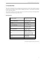
CDT Yebes O´Higgins S/X Bands Cryogenic Receiver B. Vaquero, L. Vigil, M. Patino, J.M. Serna, J.A. López Fernández, J. A. López Pérez, F. Tercero, J.M. Yagüe, J.A. Abad, C. Almendros Informe Técnico IT - CDT 2013 - 11 Revision history Version Date Updates 1.0 1.1 October 2013 April 2014 First Version Update Gain and Coupling measurements O’Higgins S/X Bands Cryogenic Receiver Index Index.................................................................................................................................................................................. 1 1. Introduction.......................................................................................................................................................... 1 Specifications .......................................................................................................................................................1 2. Cryostat geometry ............................................................................................................................................. 3 2.1. Vacuum case ...............................................................................................................................................4 2.1.1. Vacuum window ..............................................................................................................................6 2.1.2. Vacuum seals ....................................................................................................................................6 2.2. Intermediate stage and radiation shield .........................................................................................7 2.3. Cold stage .....................................................................................................................................................8 2.4. Amplifier setting-up ................................................................................................................................8 2.5. Internal DC wiring ....................................................................................................................................9 2.5.1. Low Noise Amplifiers biasing wiring ................................................................................... 11 2.5.2. Housekeeping wiring.................................................................................................................. 12 2.6. Thermal waveguide transition......................................................................................................... 13 3. Cryogenic system ............................................................................................................................................ 17 4. Cryostat thermal and vacuum behavior ................................................................................................ 19 5. Receiver calibration: noise temperature, gain and coupling ........................................................ 21 6. Low Noise Amplifiers biasing module .................................................................................................... 24 7. Installation, first use and switch off ........................................................................................................ 29 8. References .......................................................................................................................................................... 33 9. Appendix ............................................................................................................................................................. 35 9.1. S band amplifier specifications ........................................................................................................ 35 9.2. X band amplifier specifications........................................................................................................ 36 9.3. S band isolator specifications ........................................................................................................... 37 9.4. X band isolator specifications ........................................................................................................... 37 9.5. Temperature sensors specifications.............................................................................................. 38 9.6. S band coupler (narda 4013C-20) specifications ..................................................................... 39 9.7. RF Measurements .................................................................................................................................. 40 I Intentionally left in blank O’Higgins S/X Bands Cryogenic Receiver 1. Introduction This report summarizes the new design and characteristics of the S and X bands cryogenic receiver for the Geodetic Antartic Station O´Higgins developed at Technology Development Center, Yebes Observatory. The receiver is based on a two stage closed cycle cryocooler (CTI-22), the cold stage below 20 K and the intermediate stage, below 70 K. Specifications Frequency bands* S Band: 2.2-2.37 GHz X Band: 8.15-9.0 GHz Physical Temperature < 70 K radiation shield < 20 K cold stage Pressure < 10-5 mbar Pressure Leaks at room temperature (mainly outgassing) < 2 · 10-5 mbar·l/s Gain > 25 dB at S band > 30 dB at X band Noise Temperature S band: < 20 K X band: < 20 K Input S band: N connector X band: waveguide WR-112 S band calibration: SMA X band calibration: SMA Output S band: SMA X band: SMA Output impedance 50 Ω * IVS Frequency Bands for Geodetic Observations. 1 Intentionally left in blank O’Higgins S/X Bands Cryogenic Receiver 2. Cryostat geometry Next figures show the cryostat design: Figure 1. Cryostat overview (cold head (green), vacuum case (pink and violet), radiation shield (blue), cold stage (violet) and thermal transition (orange)). The cryostat design is based on the previous cryostat installed at O´Higgins Station. This new design has been performed carefully due to the little free space inside the cryostat and also taking into account the space in the receiver box. Figure 2. Previous dewar design inside the receiver box. The cryostat is built over a Model-22 CTI cold head in a steel made cylindrical dewar. At the top cover, a vacuum window (Wettzell Observatory supplied) lets the X band radiation go through, for the S band a hermetic N connector feedthrough is used. At the bottom cover there are all the RF connectors for S and X bands, the flange for the pressure sensor, DC cabling and housekeeping connectors. 3 O’Higgins S/X Bands Cryogenic Receiver Inside the cryostat, attached to the intermediate stage, there is an aluminum made cylindrical radiation shield covered with multilayer isolator (MLI). The temperature of this stage is less than 70 K. Removing the radiation shield, the entire receiver can be easily reached. It is the coldest part of the receiver at, approximately, 18 K. Both amplifiers and the directional coupler are thermally attached to the copper made cold stage. The RF cables that connect the cold stage (amplifiers and couplers) with the room temperature stage (SMA connectors and N connector) are coaxial semi-rigid steel cables, UT-085B-SS. Figure 3. Cryostat overview (current design). 2.1. Vacuum case The dewar consists of two main parts: stainless steel cylinder with the top cover and the bottom cover. At the top cover the inputs for the X and S bands are presented (vacuum window for X band and N connector adapter for S band). The dewar lower flange has several outputs for different uses: - Cold head connection: to place the cold head in the right position, a second flange was placed between the lower flange and the cold head. To get the desire vacuum two viton seals have been used. - One aperture with a transition for the vacuum control (pressure sensor). - Three hermetic Fischer connectors for the housekeeping control and monitoring, and amplifiers biasing. - Four SMA hermetic connectors for the RF input/output signals (calibration and RF). Inside the dewar, at the bottom cover, there is an aluminum plate to carry out the transition between room temperature DC wiring and the cryogenic wires, using DB connectors. 4 O’Higgins S/X Bands Cryogenic Receiver Figure 4. Dewar, vacuum seals and flange dimensions. At the cylinder there are two flanges, one for the vacuum valve and the other one closed with a blind flange (the original safety vacuum valve has been removed because its use isn´t necessary and it could be a leakage source). Figure 5. Bottom dewar cover and outer cylinder. Figure 6. Cold head flange. 5 O’Higgins S/X Bands Cryogenic Receiver 2.1.1. Vacuum window The vacuum window goal is to allow transition (physical, electromagnetic and vacuum) between the X band horn, that it is out of the cryostat, and the directional coupler. Figure 7. Vacuum window and waveguide transition. 2.1.2. Vacuum seals O-rings with their main specifications and locations are presented in the table below: Viton Seals Type d1 (mm) d2 (mm) Reference Qty Cold Head – ancillary flange – lower flange OR VI 63.22 1.78 435.803 2 * Vacuum case – bottom flange OR VI 202.57 5.33 346.631 1 OR VI 34 3 462.291 1 OR VI 116 4 425.319 1 * Vacuum sensor – lower flange OR VI 40 4.5 346.768 1 Helicoflex Seals Type d1 x dext x d2 (mm) Reference Qty Vacuum case – bottom flange Garlock Helicoflex - 128584 1 Golden transition – top flange Garlock Helicoflex 114.5 x 123.5 x 4.5 125820 1 Vacuum sensor – lower flange Garlock Helicoflex 41.5 x 50.5 x 4.5 - 1 * Vacuum window – golden transition * Golden transition – top flange Table 1: Viton vacuum seals (Epidor [5]) and Helicoflex seals. * Viton seals supplied by Wettzell. The reference belongs to an Epidor catalog compatible gasket. 6 O’Higgins S/X Bands Cryogenic Receiver 2.2. Intermediate stage and radiation shield The intermediate stage is an aluminum plate of 5 mm thickness and 182 mm diameter, screwed onto the first stage of the cold head. Attached to this plate there is an aluminum cylinder to cover the cold stage and reduce the radiation load. The radiation shield is covered with multilayer isolator, MLI (8 layers). Figure 8. Intermediate stage design and radiation shield. On the intermediate stage, a temperature sensor, a heating resistor, a thermostat and a zeolites based vacuum trap are installed. These devices have the following characteristics: - Heating resistor: 100 Ω, 25 W. - Zeolites regeneration resistor: the vacuum trap includes a 100 Ω and 2.5 W regeneration resistor. - Temperature sensor: DT-670 Lakeshore Si-diode. - Thermostat: 70° ± 3°. Figure 9. Intermediate stage installed in the cryostat and radiation shield with MLI. 7 O’Higgins S/X Bands Cryogenic Receiver 2.3. Cold stage Figure 10. Cold stage design. The cold stage consists of a three copper plates. The main one is directly attached to the cold head cold stage; the others are screwed to both sides of the first one. Attached to these plates are placed the vacuum trap, thermostat, heating resistor and the temperature sensor (same specifications than the used for the intermediate stage). The S and X LNAs and the X band directional coupler are attached to the lateral plates. Figure 11. Cold stage with LNAs and housekeeping elements. 2.4. Amplifier setting-up The cryostat contains two low noise amplifiers: - S Band LNA: TTI-LNA-S-2248-CRYO. - X Band LNA: 4-12 GHz Cryogenic LNA, YXA 1197 Detailed specifications and biasing information can be found in the appendix. 8 O’Higgins S/X Bands Cryogenic Receiver Figure 12. S band low noise amplifier. Figure 13. X band low noise amplifier. 2.5. Internal DC wiring There are 3 hermetic Fischer connectors at the dewar bottom flange (figure 5): - One of them, with 16 pin, for monitoring signals and housekeeping. Two of them, with 11 pin, for the amplifiers biasing signals. Hermetic Fischer Connector Function C1 C2 C3 Housekeeping S band LNA X band LNA Next figures show the Fischer connectors pin-out (11 and 16 pin): Figure 14: 11 pin Fischer (connector view, red point up). Figure 15: 16 pin Fischer (connector view, red point up). 9 O’Higgins S/X Bands Cryogenic Receiver The DC wiring has been done using small section long cables to reduce the conduction load. Next tables indicate the pin-out association between connectors. O´Higgins S/X receiver DC connections pin-out: Fischer Pin DB15 Pin Signal 1 2 3 4 5 6 7 8 9 10 11 1 2 3 4 5 6 7 8 9 10 11 Tc_+ Tc_Ti_+ Ti_Calef_on Regen_on GND_res Calef_mon Regen_mon (free) (free) Table 2: Fischer Connector (C1) 16 pin (housekeeping) correspondence with the DB15 connector. Fischer Pin DB9 Pin Signal 1 2 3 4 5 6 7 1 2 3 4 5 6 7 Gnd Vd1 Vg1 Vd2 Vg2 (free) (free) Table 3: Fischer Connector (C2) 11 pin (S band LNA) correspondence with the DB9 connector. Fischer Pin DB9 Pin Signal 1 2 3 4 5 6 7 1 2 3 4 5 6 7 Gnd Vd1 Vg1 Vd2 Vg2 Vd3 Vg3 Table 4: Fischer Connector (C3) 11 pin (X band LNA) correspondence with the DB9 connector. 10 O’Higgins S/X Bands Cryogenic Receiver Figure 16: DC wiring (room temperature stage). 2.5.1. Low Noise Amplifiers biasing wiring Band Amplifier frequency range (GHz) IVS Frequencies (GHz) Purpose S 2.2- 2.7 2.2 - 2.37 Geodetic VLBI X 4 - 12 8.15 - 9.0 Geodetic VLBI Next figures show the amplifier biasing connectors pin-out: Figure 17. X band amplifier biasing connector pin-out. Figure 18. S band amplifier biasing connector pin-out. 11 O’Higgins S/X Bands Cryogenic Receiver 2.5.2. Housekeeping wiring At the room temperature stage (300 K), there is a 16 pin Fischer connector placed for the cryostat internal monitoring signals: heating resistors, zeolites regeneration resistors, temperature sensors and thermostats. Fischer Pin Signal Description 1 Tc_+ Cold stage temperature sensor (+) 2 Tc_- Cold stage temperature sensor (-) 3 Ti_+ Intermediate stage temperature sensor (+) 4 Ti_- 5 Calef_on 6 Regen_on 7 GND_res Intermediate stage temperature sensor (-) Signal to activate the heaters after passing through the thermostat Signal to activate the zeolites regeneration resistor after passing through the thermostat Ground 8 Calef_mon Thermostat verification (heating resistors) 9 Regen_mon Thermostat verification (regeneration resistors) Table 5. Housekeeping signals description. A 5-meters-lenght cable is supplied to connect the receiver with the different housekeeping signals. At one end there is the 16 pin Fischer connector to be plugged to the receiver. The other end contains the following elements: Fischer Pin Signal Color DB25 pin Banana Connectors 1 Tc_+ Black 3, 4 2 Tc_- Grey 15, 16 3 Ti_+ Violet 6, 7 4 Ti_- Green 18, 19 5 Calef_on Blue Red 6 Regen_on Brown Yellow 7 GND_res Orange Black 8 Calef_mon Red Red (test point) 9 Regen_mon White Black (test point) Table 6. Housekeeping 5 m cable description. - DB25 connector: to Lakeshore 218 system (positions one and two), DT 670 sensors. Banana connectors: power supply for the receiver heating resistors and zeolites regeneration resistor. 12 O’Higgins S/X Bands Cryogenic Receiver 2.6. Thermal waveguide transition For the X band signal input, a thermal waveguide transition with a directional coupler have been designed, built and measured at Yebes Observatory laboratories. The transition optimization was carried out with the HFSS software and designed with Autocad. The rectangular input waveguide undergoes to a high temperature gradient, from the room temperature stage to the cold stage. To avoid this sudden temperature change a thermal transition has been designed for the working frequency (8-9 GHz). Figure 19: X band thermal transition and directional coupler. The transition is made facing two rectangular waveguides, one with a smooth flange cover type and the other one is choke type, separated by a small gap. The choke depth is λ/4 to cancel the parallel components of the electric field flowing through the gap avoiding losses and resonances at the working frequency. Besides the thermal transition, a directional coupler was designed. This coupler is attached to the transition through a second gap. With this design the thermal transition is double stage, since there are two temperature stages from 300 K to 70 K and from 70K to 20 K. The gaps are achieved by means of fiber glass pieces. This material exhibits a very low thermal conductivity. Furthermore, a polystyrene IR filter has been placed within the guide to minimize the radiation load inside the guide. 13 O’Higgins S/X Bands Cryogenic Receiver Figure 20: Thermal transition and directional coupler. The previous structure was measured using the vector network analyzer. The relevant values of the measurements are presented in table 7. Figure 21. Chain insertion loss. Figure 22: Return losses (ports 1 and 2). 14 O’Higgins S/X Bands Cryogenic Receiver Figure 23. Isolation and return losses (port 3). Figure 24. Coupling factor. Figure 25. Waveguide losses. Parameter Value (dB) Description Figure L - 0.16 Insertion Loss 21 RL1,2 < - 20 Return Losses Ports 1 and 2 22 RL3 < - 22 Return Losses Port 3 23 C - 27 Coupling Factor 24 ISO < - 45 Isolation 23 Lg - 0.1 Waveguide Losses 35 Table 7. Thermal transition with directional coupler final measurements. 15 Intentionally left in blank O’Higgins S/X Bands Cryogenic Receiver 3. Cryogenic system This receiver uses a Model 22 CTI-Cryogenics Cold Head, with the following characteristics: Figure 26. 22C cryodyne cryocooler typical refrigeration capacity (50 Hz). 17 Intentionally left in blank O’Higgins S/X Bands Cryogenic Receiver 4. Cryostat thermal and vacuum behavior Several tests have been performed to determine the cryostat thermal and vacuum behavior. Cooling and pumping systems: - Cold head: CTI 22. - Compressor: CTI 8200, 220 V - 50 Hz. - Vacuum system: Rotary pump and turbomolecular pump (Alcatel). Vacuum sensors (MKS): Pirani sensor (pressure from atmospheric to 10-4 mbar) and cold cathode (pressure from 10-4 mbar to 10-8 mbar). Measurement, final results: - Intermediate stage temperature: ≤ 68 K. - Cold stage temperature: ≤ 18 K. - Vacuum <10-5 mbar (cryogenic vacuum). Leakage rate 1.3 · 10-5 mbar·l/s (1,6 · 10-6 mbar/s). - Cooling down time: < 12 h. - Warming up time: < 30 h (or < 3.5 h with zeolites regeneration and heating resistors turned on). Figure 27. Cooling test (zeolites regeneration and heating resistors turned on to warm the cryostat). 19 O’Higgins S/X Bands Cryogenic Receiver Figure 28. Intermediate stage load ≈4.6 W, cold stage load ≈1 W. Figure 29. Vacuum test (Pirani sensor) and thermal behavior during the vacuum test, (zeolites regeneration and heating resistors turned on during the first 11 hours). 20 O’Higgins S/X Bands Cryogenic Receiver 5. Receiver calibration: noise temperature, gain and coupling The Y factor method has been used to calibrate the receiver (measure the noise temperature). The noise temperature measurement is carried out connecting the receiver input to different adapted loads with known temperatures. When the load at the input has a temperature, TH, the power at the output is PH, hot load. If a second measure is done with a load with a different temperature, TC, the power will be different, PC, cold load. Then, the receiver noise temperature can be calculated by the following expressions: This method is based on the hypothesis that the receiver behavior is linear between P H and PC. The thermal loads used, for these measurements, are: - Hot load: coaxial SMA 50 Ω load at room temperature, ≈ 297 K. - Cold load: coaxial SMA 50 Ω load submerged in liquid nitrogen, ≈ 77 K. The following results shows the receiver noise temperature without taking into account the losses due to the cables, SMA connectors, N-N hermetic transition, waveguide transition, etc. Figure 30. Receiver calibration. 21 O’Higgins S/X Bands Cryogenic Receiver LNAs Noise Temperature measured at room temperature X band S band TH= = 297 K TC = 77.3 K TH= = 297 K TC = 77.3 K Freq. (GHz) Noise Temp. (K) Freq. (GHz) Noise Temp. (K) 8 8.1 8.2 8.3 8.4 8.5 8.6 8.7 8.8 8.9 9 293.33 274.77 282.78 326.41 370.05 376.35 355.46 376.68 348.86 381.36 376.91 2 2.1 2.2 2.3 2.4 2.5 2.6 128.07 133.62 110.52 106.28 125.23 95.77 165.43 Figure 31. TRX at room temperature (LNAs at ≈ 297 K). 22 O’Higgins S/X Bands Cryogenic Receiver LNAs Noise Temperature measured at cold temperature X band S band TH = 297 K TC = 77.3 K TH= = 297 K TC = 77.3 K Freq. (GHz) Noise Temp. (K) Freq. (GHz) Noise Temp. (K) 8 8.1 8.2 8.3 8.4 8.5 8.6 8.7 8.8 8.9 9 12.96 11.55 12.77 14.37 15.36 13.98 12.94 14.34 15.70 16.22 15.20 2 2.1 2.2 2.3 2.4 2.5 2.6 11.59 12.98 12.98 13.37 13.77 17.97 18.24 Figure 32. TRX at cold temperature (LNAs at ≈ 18 K). 23 O’Higgins S/X Bands Cryogenic Receiver LNAs Gain and Coupling measured at cold temperature X Band S Band Freq. (Ghz) Gain (dB) Coupling (dB) Freq. (Ghz) Gain (dB) Coupling (dB) 8 31.4 -29.6 2 25.3 -21.2 8.1 31.8 -29.4 2.1 25.6 -21 8.2 31.3 -29.8 2.2 26 -20.8 8.3 31.8 -29.8 2.3 26.1 -20.7 8.4 31.9 -29.3 2.4 25.5 -20.4 8.5 31.1 -29 2.5 25.2 -20.4 8.6 30.8 -29.9 2.6 24.8 -20.3 8.7 31 -29.9 8.8 30.7 -29.1 8.9 31.1 -29.8 9 30.9 -29.1 Figure 33. Gain and coupling at cold temperature (LNAs at ≈ 18 K). 24 O’Higgins S/X Bands Cryogenic Receiver 6. Low Noise Amplifiers biasing module With the receiver, a biasing module for the low noise amplifiers is supplied. Figure 34. LNAs biasing module and 5 m cables for X and S band amplifiers. The biasing module is already adjusted for the indicated S and X LNAs biasing points. However, the back cover of the biasing module can be removed for accessing to the biasing power supply cards (the schematics of the cards are shown in figure 35). The card, used for the S LNA, allows the adjustment of two stages and the card for the X LNA three stages. Vd and Id can be adjusted for each stage by means of the corresponding potentiometer. S LNA Vd1 Id1 Vg1 Vd2 Id2 Vg2 1.2 V 7 mA -2.01 V 0.8 V 5 mA -2.6 V LNAs Biasing Module Consume +15 V ≈ 107 mA -15 V ≈ 70 mA X LNA Vd1 Id1 Vg1 Vd2 Id2 Vg2 Vd3 Id3 Vg3 0.95 V 4.5 mA -1.57 V 0.75 V 3.5 mA -1.02 V 0.75 V 3.5 mA -0.94 V Table 8. LNAs biasing (cold temperature 15K). The biasing values can be monitored through a DB25 female connector placed at the module front panel. Read values could be slightly different to the real ones due to cable ohmic losses. When adjusting (only if necessary), read the values directly through the pins in the card. Low Noise Amplifiers biasing procedure: - Connect Fischer connectors to the corresponding connectors (S and X) on the dewar. Connect DB9 connectors to the S and X inputs. Connect a power supply to the +15 V and -15 V inputs. Turn on power supply and verify electric current values. 25 O’Higgins S/X Bands Cryogenic Receiver Figure 35. PC Board Components. LNAs Biasing Monitor DB25 Connector Pin-out DB25 pin Signal Wire color 1 2 GND Vg1 - S Brown Pink, blue dots 3 Id1 - S Yellow, blue dots 4 Vd1 - S Red, blue dots 5 Vg2 - S Yellow, pink dots 6 Id2 - S Brown, blue dots 7 Vd2 - S Brown, dark blue dots 8 9 Vg1 - X Id1 - X Green, blue dots White, pink dots 10 Vd1 - X Yellow, red dots 11 Vg2 - X White, yellow dots 12 13 Id2 - X Vd2 - X Brown, green dots Green, blue dots 14 15 Vg3 - X Id3 - X Grey, green dots Grey, brown dots 16 Vd3 - X White, blue dots Table 9. LNAs Biasing Monitor DB25 Connector pin-out. 26 O’Higgins S/X Bands Cryogenic Receiver Biasing cables pin-out Fischer Pin (F) DB9 Pin Wire color Signal 1 2 3 4 5 6 7 1 2 3 4 5 6 7 Black Blue Yellow Orange Red Brown Grey Gnd Vd1 Vg1 Vd2 Vg2 (free) (free) Table 10. S band, 5 m cable description. Fischer Pin (F) DB9 Pin Wire color Signal 1 2 3 4 5 6 7 1 2 3 4 5 6 7 Black Brown Yellow Orange Green Blue Violet Gnd Vd1 Vg1 Vd2 Vg2 Vd3 Vg3 Table 11. X band, 5 m cable description. 27 Intentionally left in blank O’Higgins S/X Bands Cryogenic Receiver 7. Installation, first use and switch off For receiver installation proceed as follows: - Vacuum controller, temperature monitor system, LNA bias module and RF module must be switched off. - Pumping Connect housekeeping cable to the Fischer connector at cryostat rear side (C1) (figure 5). Connect the vacuum controller to the vacuum sensor Quadmag. Connect the vacuum valve to the corresponding vacuum flange (the valve must be closed). Switch on the vacuum controller. The vacuum sensor will start the set up and a green led will light continuously when ready. The vacuum controller will show atmospheric pressure. Switch on the temperature monitor (housekeeping cable has a DB25 connector for the Lakeshore connector input). The temperature of the first 2 channels will be around room temperature. Connect the vacuum system (rotary pump and turbomolecular) to the vacuum valve. Start running the rotary pump for a few minutes. Slowly open the valve. The vacuum level will start to decrease. During this procedure avoid any abrupt opening of the valve. When the vacuum is about 10-1 mbar, start turbomolecular operation. Connect the regeneration resistor banana connector to a power supply. Connect the heating resistor banana connectors to a power supply. - Black: GND Yellow:+6.17 V, ≈112 mA Black: GND Red: +25.7 V, ≈498 mA Leave the system running in the above conditions for 12 hours. Then, the resistors can be turned off. The vacuum system should be pumping at least for 12 more hours. Connecting the helium compressor Warning! Be sure the helium pipes and compressor pressure is correct (as indicated in the user’s manual) and they are not contaminated. Remove all dust plugs and caps from the helium supply and return lines, compressor and cold head. Check all fittings. Connect the helium return line between the compressor and the cold head. Connect the helium supply line between the compressor and the cold head. Verify proper helium supply static pressure (245 psi for CTI 8200 compressor). If the indicated pressure is not the specified by the compressor manufacturer, follow the instructions supplied by the manufacturer. Connect the cold head cable between the compressor and the cold head. 29 O’Higgins S/X Bands Cryogenic Receiver Figure 36. O´Higgins cryostat vacuum and cooling test. - - Connecting the LNAs biasing module Connect the LNAs biasing module to a power supply (+15 V, -15 V, GND). Power supply off. Plug the S and X bands LNAs biasing cables between the LNA Bias Module and the cryostat (figure 5). Cryostat Connector LNA Biasing Module C2 C3 S band LNA X band LNA The LNAs biasing points are already set up. In case a verification or change is needed, go to chapter 6. Turn on the power supply (verify correct electric current values, table 8). First use After 24 hours pumping the system is ready to start the cooling down process. Warning! Be sure your vacuum system can be used during cooling process. For carrying out this process, (usually) it is necessary to have a rotary and a turbomolecular pump. Just using a rotary pump, at low temperatures, can cause vacuum inversion. It is important to verify the turbomolecular pump behavior during the process. The pressure inside the receiver should be at 5·10-3 mbar or lower. Switch on the compressor. The temperatures will start decreasing. The vacuum valve has to be opened until the intermediate stage reaches, at least, 120 K. If it is allowed by the pumping system, the valve can be opened until the system achieves the final temperatures. After 10-11 hours the cryostat will reach its operational cryogenic temperature and pressure. Temperature radiation shield Temperature cold stage Pressure < 70 K < 20 K < 10-5 mbar 30 O’Higgins S/X Bands Cryogenic Receiver - Switch off For switching off the system proceed as follows: Be sure that the pumping valve is closed. Switch off the compressor. Switch off the LNAs biasing module. Leave the cryostat warming to room temperature. This can be verified at the temperature monitor. This process can be accelerated by turning on the heating resistors (+25 V) and the zeolites regeneration resistors (+6 V). Once the system is at room temperature, open slowly the vacuum valve to achieve atmospheric pressure inside the cryostat. Warning! Be careful with the temperature values when using zeolites regeneration and heating resistors to warm the cryostat. Once the final room temperature is achieved, do not to open the dewar immediately. It is necessary to wait for a few minutes for the temperature system to be stabilized with the resistors turned off. If the dewar is opened too soon, water vapor can appear inside the cryostat and it could cause damages. 31 Intentionally left in blank O’Higgins S/X Bands Cryogenic Receiver 8. References [1] Behrens, G., Campbell, W., Williams, D., White, S.. Guidelines for de Design of Cryogenic Systems. National Radio Astronomy Observatory (NRAO), Green Bank, West Virginia. 1997. [2] CTI-Cryogenics cryodyne refrigeration systems. Helix Techonology Corporation, 2002, USA. [3] Díaz, F., Becerro, J.. S Cryogenic Low Noise Amplifier. TTI 2013. [4] DT-670 Sensor Catalog. Lakeshore. (http://www.lakeshore.com/Documents/LSTC_DT670_l.pdf) [5] Juntas tóricas. Epidor Catalog (O-rings). [6] López, J.A., Gallego, J.D., de Vicente, P., Abad, J.A., Almendros, C.. Criostato del receptor S/X de VLBI del CAY. Informe técnico IT OAN 1994-6. [7] Malo, I., López Fernández, J. A., Tercero, F., Abad, J.A., Almendros, C., Fernández, J., Yagüe, J.M.. Criostato del receptor de GHz del CAY. Informe técnico IT OAN 2005-12. [8] Multiple Uses of Model 22C/350C Cryodyne® Refrigerators Installation, Operation andServicing Instructions. Brooks. USA. [9] Serna Puente, J. M., López Fernández, J. A., López Pérez, J. A., Tercero, F., et al. Nuevo receptor banda C de la antena Aries del Observatorio de Yebes. Informe técnico IT OAN 2010-14. [10] Serna Puente, J. M., López Fernández, J. A., Tercero, F., et al. Receptor criogénico bandas K/Q de la Antena Aries del Centro de Desarrollos Tecnológicos de Yebes. Informe técnico IT OAN 2013. [11] Tercero, F., Vigil, L., López Fernández, J. A.. Diseño y construcción de una transición en guía de ondas y acoplador direccional en banda X para el criostato alemán en O´Higgins. Informe Técnico CDT 2013-9. [12] Vaquero, B., Serna Puente, J. M., López Fernández, J. A., Tercero, F., López-Pérez, J.A., Patino, M., et al. Wettzell S/X Bands Cryogenic Receiver. Informe Técnico CDT 2013-4. [13] 4-12 GHz Cryogenic LNA YXA 1197. Centro Astronómico de Yebes. 33 Intentionally left in blank O’Higgins S/X Bands Cryogenic Receiver 9. Appendix 9.1. S band amplifier specifications DC connector pin-out. Amplifier external view. 35 O’Higgins S/X Bands Cryogenic Receiver 9.2. X band amplifier specifications Amplifier external view. DC connector pin-out. 36 O’Higgins S/X Bands Cryogenic Receiver 9.3. S band isolator specifications 9.4. X band isolator specifications 37 O’Higgins S/X Bands Cryogenic Receiver 9.5. Temperature sensors specifications 38 O’Higgins S/X Bands Cryogenic Receiver 9.6. S band coupler (narda 4013C-20) specifications 39 O’Higgins S/X Bands Cryogenic Receiver 9.7. RF Measurements S band input cable, UT-85B-SS, 5 cm length. S band output cable, UT-85B-SS. 40 O’Higgins S/X Bands Cryogenic Receiver S band calibration input cable, UT-85B-SS. S band hand-formable cable (directional coupler - isolator). 41 O’Higgins S/X Bands Cryogenic Receiver X band output cable, UT-85B-SS. X band calibration input cable, UT-85B-SS. 42 O’Higgins S/X Bands Cryogenic Receiver X band hand-formable cable (thermal transition - isolator). O´Higgins S/X Bands Cryogenic Receiver CDT Yebes 2013