1
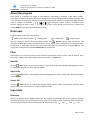
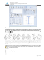
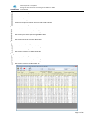
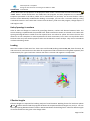
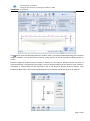
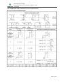
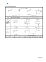
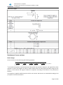
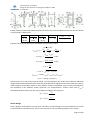
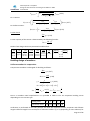
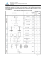
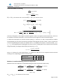
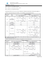
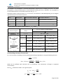
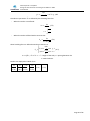
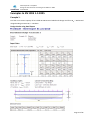
Software Package Design Expert version 2.7 Structural Design and Detailing to Eurocode Steel Expert EC Design of steel elements according to EN 1993-1-1:2005 User manual All rights reserved 2014 Steel Expert EC v 2.5/2014 Design of steel elements according to EN 1993-1-1:2005 User Manual TABLE OF CONTENTS About the program .................................................................................................................... 3 Data input ................................................................................................................................. 3 Files ........................................................................................................................................... 3 New file............................................................................................................................................ 3 Open a file........................................................................................................................................ 3 Save a file ......................................................................................................................................... 3 Input data.................................................................................................................................. 3 Materials .......................................................................................................................................... 3 Cross sections ................................................................................................................................... 4 Holes/openings in sections ............................................................................................................... 6 Loading ............................................................................................................................................ 6 Effective lengths ............................................................................................................................... 6 Design to EN 1993-1-1:2005 ....................................................................................................... 8 Classification of cross sections .......................................................................................................... 8 Resistance of cross sections ............................................................................................................ 11 Elastic design ........................................................................................................................................11 Plastic design ........................................................................................................................................12 Buckling design of members ........................................................................................................... 15 Uniform members in compression ......................................................................................................15 Uniform members in bending ..............................................................................................................17 Members in combined bending with axial compression .....................................................................17 Local buckling resistance of beam webs ..............................................................................................19 Examples to EN 1993 1-1:2005 ................................................................................................. 21 Example 1....................................................................................................................................... 21 Design checks using Steel Expert .........................................................................................................21 Manual checks .....................................................................................................................................22 Example 2....................................................................................................................................... 23 Design checks using Steel Expert .........................................................................................................23 Manual checks .....................................................................................................................................24 Example 3....................................................................................................................................... 25 Design checks using Steel Expert .........................................................................................................25 Manual checks .....................................................................................................................................26 Example 4....................................................................................................................................... 27 Design checks using Steel Expert .........................................................................................................27 Manual checks .....................................................................................................................................28 Example 5....................................................................................................................................... 29 Design checks using Steel Expert .........................................................................................................29 Manual checks .....................................................................................................................................30 Example 6....................................................................................................................................... 31 Design checks using Steel Expert .........................................................................................................31 Manual checks .....................................................................................................................................32 Example 7....................................................................................................................................... 33 Calculations using Steel Expert ............................................................................................................33 Manual checks .....................................................................................................................................34 Calculation Report ................................................................................................................... 35 Page 2 of 35 Steel Expert EC v 2.5/2014 Design of steel elements according to EN 1993-1-1:2005 User Manual About the program Steel expert is a software for design of steel elements according to Eurocode 3 (EN 1993-1-1:2005). Calculations include elastic and plastic section design, local buckling and element buckling for combined axial force (tension or compression), bending moments in two directions, shear forces and torsion. Eight different types of sections are available . The program includes a library of standard steel sections. Option for holes in webs and flanges is available as well. Results are presented in professional looking HTML format report for viewing and printing. Data input Program data is divided into several pages: Materials and Sections Data Buckling Data Loading Data Design Results Click the respective button to switch between pages. The "Results" button starts calculations and generates an html report, which is displayed on the screen. Input values are entered in the respective tables or text fields on each page. You can move to the next field either by mouse click or using the Tab key. You can go back to the previous field with Shift+Tab keys combination. Files Steel Expert has its own file format and the data for each problem can be saved to a file on the disk. Input files have * .stl extension, while design results are stored in * .stl.html files. New file Click the “New” button to save current data to a new file. A standard file selection dialog appears. Select or write down file path and name and click "Save". Open a file Click the "Open" button. A standard file selection dialog appears. Select or write down file path and name and click "Open". Save a file Click the "Save" button. A standard file selection dialog appears. Select or write down file name. If file already exists, you can overwrite it or select a different name. Input data Materials Select steel grade from the "Steel" combo box. The program automatically fills in the respective strength properties fyk and fuk. You can also input custom values for fy and fu for steel grades that are not included in the library. Partial safety factors are also required. Default values are: M0 = 1.05, M1 = 1.05, M2 = 1.25. Page 3 of 35 Steel Expert EC v 2.5/2014 Design of steel elements according to EN 1993-1-1:2005 User Manual Cross sections Eight different shape types are available. Sections can be standard hot-rolled, cold formed, built-up, welded etc. If you have a non-standard cross section, you should select the shape from the respective button ( ) and enter the dimensions manually. Notations for dimensions and axes for different shapes are as follows: Area properties are calculated precisely, including fillets. There is no option for tapered flanges of nonstandard sections, so they should be entered as parallel with average thickness. In this case section properties are approximate. Torsional properties are calculated by approximate formulas with precision of 1% – 2%. Standard cross sections can be selected from the "Steel Sections Library. The library is opened by the "Open" button located next to shapes buttons. Select section type according to the respective standard European, British, Russian or Bulgarian. European Hot rolled equal angles to EN 10056-1 Hot rolled unequal angles to EN 10056-1 Hot rolled normal channels to NF A 45-202 Hot rolled I-sections IPE to EN 89 Page 4 of 35 Steel Expert EC v 2.5/2014 Design of steel elements according to EN 1993-1-1:2005 User Manual Hot rolled wide flange I-sections HE to EN 53-62 Hot rolled circular hollow sections CHS to EN 10210-2 Hot rolled square hollow sections SHS to EN 10210-2 Hot rolled rectangular hollow sections RHS to EN 10210-2 Cold formed square hollow sections SHS to EN 10219-2 Cold formed rectangular hollow sections RHS to EN 10219-2 British Hot rolled channels with taper flanges RSC to BS4 Hot rolled channels with parallel flanges PFC to BS4 Hot rolled joists with taper flanges RSJ to BS4 Hot rolled universal beams UB to BS4 Hot rolled universal columns UC to BS4 Russian Hot rolled unequal angles to GOST 8510-72 Hot rolled I-sections with parallel flanges to GOST 2620-83 Hot rolled wide flange I-sections to GOST 2620-83 Hot rolled I-columns to GOST 2620-83 Bulgarian Hot rolled equal angles to BDS 2612-73 Hot rolled channels with tapered flanges to BDS 6176-75 Hot rolled channels with parallel flanges to BDS 6176-75 Hot rolled I-sections to BDS 5951-75 Page 5 of 35 Steel Expert EC v 2.5/2014 Design of steel elements according to EN 1993-1-1:2005 User Manual Section dimensions and properties are displayed in tables. Select a section with the mouse and click the “Load” button. Section dimensions are loaded into the program and area properties are re-calculated. Properties presented in the library tables are for information only and they are not used further. Library sections can be additionally modified after loading. For example, you can enter a T-section made by cutting a standard I-section in two. Select the I-section from the library, load it into the program, change shape to T and height to half. Holes/openings in sections Holes in webs and flanges are entered by specifying diameter, number and distance between holes. The section drawing is updated with the specified holes. Holes outside the section are colored in red. Holes with spacing and edge distances smaller than the required ones are colored in yellow. This alerts the user that distances are non-compliant to code requirements for bolt connections, but it does not stop further work because holes may have another purpose. Holes are considered in section analysis. They are not considered in element buckling checks. Loading Select the number of load cases first. Then enter axial force N, bending moments My, Mz, shear forces Vy, Vz and torsion T for each load case in the table. All components will be considered as acting both separately and simultaneously for a given load case. Positive axial force is tension and negative is compression. Effective lengths Effective lengths are required for buckling analysis of steel elements. Buckling factors for both main planes y andz shall be entered and the program calculates the respective effective lengths Lefy and Lefz . You can also input spacing between lateral restraints. Recommendations for buckling factor values for different types of structural elements are given in the design codes. Page 6 of 35 Steel Expert EC v 2.5/2014 Design of steel elements according to EN 1993-1-1:2005 User Manual The button opens the “Buckling calculator” window, where can be calculated depending on the selected support conditions. You can have pinned, fixed or spring restraint as well as restraint provided by beams in frames. Effective length for lateral-torsional buckling is defined as the distance between lateral restraints of compressed flange. Load positions (top flange, neutral or bottom flange) and load patterns (end moments, distributed or concentrated) are also required as well as the shapes of bending moment diagram. Local buckling of beam webs is also checked. Stiffening ribs can be defined and rib spacing a can be entered. Page 7 of 35 Steel Expert EC v 2.5/2014 Design of steel elements according to EN 1993-1-1:2005 User Manual Design to EN 1993-1-1:2005 Classification of cross sections Section class is determined based on the assumption that section is loaded either with uniform compression or bending. Class is determined for each part of the section, using Table 5.1 for the respective stress diagram. In case of bending of non-symmetrical sections, equations for bending and compressive stress calculation are used. Factor c/t is determined assuming that neutral line passes through the center of area. Sections class 1 and 2 are designed for plastic resistance and sections class 3 – for elastic resistance. Sections class 4 are not designed in the current version. In these sections local buckling occurs before steel yielding. The most conservative result from the classification of separate parts is relevant for the whole section. If no compression is defined, classification for compression is not taken into account. If no bending moments are defined, classification for bending is not taken into account, respectively. In case of bending with axial force this approach gives conservative results. Take for instance a beam with IPE 400 section, loaded with bending moment of 300 KN.m and compression of -0,10 KN. Web shall be classified as Class 1 for bending and Class 4 for compression. But final class for the section is Class 4, due to the presence of compression. In such cases, when the effects of compressive force upon the final stresses is negligible, it is better to assume exactly zero. Results of section classification are provided in tabular form: Compression Bending Class 4 Class 1 Flanges Class 1 Class 1 Web Page 8 of 35 Steel Expert EC v 2.5/2014 Design of steel elements according to EN 1993-1-1:2005 User Manual Table 5.2. Maximum width-to-thickness ratios for compression parts Sheet 1 of 3. Internal compression parts. Page 9 of 35 Steel Expert EC v 2.5/2014 Design of steel elements according to EN 1993-1-1:2005 User Manual Sheet 2 of 3. Outstand flanges. Page 10 of 35 Steel Expert EC v 2.5/2014 Design of steel elements according to EN 1993-1-1:2005 User Manual Sheet 3 of 3. Angles Resistance of cross sections Elastic design Class 3 sections are checked using the following equation: 2 √( 2 2 𝜎𝑥,𝐸𝑑 𝜎𝑧,𝐸𝑑 𝜎𝑥,𝐸𝑑 𝜎𝑧,𝐸𝑑 𝜏𝐸𝑑 ) +( ) −( )( )+ 3( ) ≤ 1 (6.1)∗ 𝑓𝑦 /𝛾𝑀0 𝑓𝑦 /𝛾𝑀0 𝑓𝑦 /𝛾𝑀0 𝑓𝑦 /𝛾𝑀0 𝑓𝑦 /𝛾𝑀0 * In Eurocode this equation is presented without the square root operation. However, the original form of the equation is used in the program in order to obtain realistic factor of safety (FOS) and safety margin for the section. In this manual, the original notations of equations according to EN 1993-1-1 are presented in brackets. This equation is applied to different points of the cross section and stresses are calculated according to the principles of structural mechanics. Page 11 of 35 Steel Expert EC v 2.5/2014 Design of steel elements according to EN 1993-1-1:2005 User Manual Design checks for points with maximum values for normal, shear and combined stresses are relevant. Results are presented in tabular form. 𝜎𝑥,𝐸𝑑 𝑓𝑦 /𝛾𝑀0 (6.42) 𝜏𝑥𝑦,𝐸𝑑 𝜏𝑥𝑧,𝐸𝑑 𝜏𝑚𝑎𝑥,𝐸𝑑 𝑓𝑦 /√3𝛾𝑀0 (6.19) 𝑓𝑦 /√3𝛾𝑀0 (6.19) 𝑓𝑦 /√3𝛾𝑀0 √𝜎𝑥,𝐸𝑑 2 + 3𝜏𝐸𝑑 2 𝑓𝑦 /𝛾𝑀0 Equations (6.19) and (6.42) may be considered as partial cases of (6.1). 1/√3 ≈ 0.58 𝜎𝑥,𝐸𝑑 (𝑦, 𝑧) = 𝑁𝐸𝑑 𝑀𝑦,𝐸𝑑 𝑀𝑧,𝐸𝑑 ± ∙𝑧± ∙ 𝑦 𝐴 𝐼𝑦 𝐼𝑧 𝜏𝑥𝑧,𝐸𝑑 (𝑦) = 𝑉𝑧,𝐸𝑑 ∙ 𝑆𝑧 (𝑦) (6.20) 𝑏(𝑦) ∙ 𝐼𝑦 𝜏𝑥𝑦,𝐸𝑑 (𝑧) = 𝑉𝑦,𝐸𝑑 ∙ 𝑆𝑦 (𝑧) (6.20) 𝑏(𝑧) ∙ 𝐼𝑧 𝜏 𝑇,𝐸𝑑 = 𝑇𝐸𝑑 𝑊𝑡 𝜏𝑟𝑒𝑑,𝐸𝑑 = √𝜏𝑥𝑦,𝐸𝑑 2 + 𝜏𝑥𝑧,𝐸𝑑 2 𝜏𝑀𝑎𝑥,𝐸𝑑 = max(𝜏𝑥𝑦,𝐸𝑑 | 𝜏𝑥𝑧,𝐸𝑑 |𝜏 𝑇,𝐸𝑑 |𝜏𝑟𝑒𝑑,𝐸𝑑 ) 𝜎𝑥,𝐸𝑑 = max(𝜎1 | 𝜎2 |𝜎3 |𝜎4 ) Normal stress z,Ed, due to local transverse load, is not considered in this version of the software. Additional design checks should be performed in zones with local effects from significant transverse loads (for instance, under supports of secondary beams or crane wheels). If holes are specified, they are always considered in the calculation of the effective section properties. For unsymmetrical I sections, shear force Vy,Ed is distributed between bottom (1) and top (2) flange according to the equations: 𝐼𝑓1 𝑉𝑦,1 = 𝑉𝑦,𝐸𝑑 𝐼𝑓1 + 𝐼𝑓2 𝑉𝑦,2 = 𝑉𝑦,𝐸𝑑 𝐼𝑓2 𝐼𝑓1 + 𝐼𝑓2 Plastic design Plastic design is performed for sections Class 1 and Class 2. Elastic design is also performed but the results are presented for information only. They are not relevant for the final bearing capacity of the section. Page 12 of 35 Steel Expert EC v 2.5/2014 Design of steel elements according to EN 1993-1-1:2005 User Manual Design checks for uniform tension: 𝑁𝐸𝑑 ≤ 1 (6.5) 𝑁𝑡,𝑅𝑑 Tension capacity of the section is determined according to the equation: 𝐴 ∙ 𝑓𝑦 𝑁𝑝𝑙,𝑅𝑑 = (6.6) 𝛾𝑀0 In case of holes, this check is performed using the effective section properties. 𝑁𝑢,𝑅𝑑 = 0.9𝐴𝑛𝑒𝑡 ∙ 𝑓𝑢 (6.7) 𝛾𝑀2 Design check for uniform compression: 𝑁𝐸𝑑 ≤ 1 (6.9) 𝑁𝑐,𝑅𝑑 Compression capacity of the section is determined according to the equation: 𝐴 ∙ 𝑓𝑦 𝑁𝑐,𝑅𝑑 = (6.10) 𝛾𝑀0 Reduced bearing capacity for axial force 𝑁𝑝𝑙,𝑉,𝑅𝑑 is calculated instead of 𝑁𝑝𝑙,𝑅𝑑 and 𝑁𝑐,𝑅𝑑 in case of design shear force 𝑉𝐸𝑑 ≥ 0.5𝑉𝑝𝑙,𝑅𝑑 and reduced yield strength is used for shear area instead of 𝑓𝑦 : 2𝑉𝐸𝑑 𝑉𝑝𝑙,𝑅𝑑 (1 − 𝜌)𝑓𝑦 (6.29) , where 𝜌 = ( 2 − 1) When torsion is present, factor is computed with 𝑉𝑝𝑙,𝑇,𝑅𝑑 instead of 𝑉𝑝𝑙,𝑅𝑑 . Bending check 𝑀𝐸𝑑 ≤ 1 (6.12) 𝑀𝑐,𝑅𝑑 Bending capacity of the section is determined according to the equations: 𝑊𝑝𝑙,𝑦 ∙ 𝑓𝑦 (6.13) 𝛾𝑀0 𝑊𝑝𝑙,𝑧 ∙ 𝑓𝑦 = (6.13) 𝛾𝑀0 𝑀𝑦,𝑅𝑑 = 𝑀𝑝𝑙,𝑦,𝑅𝑑 = 𝑀𝑧,𝑅𝑑 = 𝑀𝑝𝑙,𝑧,𝑅𝑑 When bending moment and axial force are present, design check is performed according to equation: 𝑀𝐸𝑑 ≤ 1 (6.31) 𝑀𝑁,𝑅𝑑 Bearing capacity of the section for bending with axial force is determined according to the equations: For rectangular section: 2 𝑀𝑁,𝑅𝑑 𝑁𝐸𝑑 = 𝑀𝑝𝑙,𝑅𝑑 [1 − ( ) ] (6.32) 𝑁𝑝𝑙,𝑅𝑑 For I section: 𝑀𝑁,𝑦,𝑅𝑑 = 𝑀𝑝𝑙,𝑦,𝑅𝑑 1−𝑛 (6.36) 1 − 0.5𝑎 For 𝑛 ≤ 𝑎: 𝑀𝑁,𝑧,𝑅𝑑 = 𝑀𝑝𝑙,𝑧,𝑅𝑑 (6.37) 𝑛−𝑎 2 For 𝑛 > 𝑎: 𝑀𝑁,𝑧,𝑅𝑑 = 𝑀𝑝𝑙,𝑧,𝑅𝑑 [1 − ( 1−𝑎 ) ] (6.38) Page 13 of 35 Steel Expert EC v 2.5/2014 Design of steel elements according to EN 1993-1-1:2005 User Manual 𝑛= 𝑎= 𝑁𝐸𝑑 𝑁𝑝𝑙,𝑅𝑑 𝐴 − 2𝑏𝑡𝑓 𝐴 For hollow sections: 1−𝑛 (6.39) 1 − 0.5𝑎𝑤 1−𝑛 = 𝑀𝑝𝑙,𝑧,𝑅𝑑 ∙ (6.40) 1 − 0.5𝑎𝑓 𝑀𝑁,𝑦,𝑅𝑑 = 𝑀𝑝𝑙,𝑦,𝑅𝑑 ∙ 𝑀𝑁,𝑧,𝑅𝑑 𝐴 − 2𝑏𝑡𝑓 𝐴 𝐴 − 2𝑏𝑡𝑤 𝑎𝑓 = 𝐴 𝑎𝑤 = Design check for biaxial bending 𝛼 𝛽 𝑀𝑦,𝐸𝑑 𝑀𝑧,𝐸𝑑 ( ) +( ) ≤ 1 (6.41) 𝑀𝑦,𝑅𝑑 𝑀𝑧,𝑅𝑑 For I sections: = 2, = 5n ≥ 1 For circular hollow sections: = 2, = 2 For rectangular hollow sections: = = 1.66/(1−1.13n2) For biaxial bending with axial force, 𝑀𝑦,𝑅𝑑 and 𝑀𝑧,𝑅𝑑 are replaced in equation 6.41 by 𝑀𝑁,𝑦,𝑅𝑑 and 𝑀𝑁,𝑧,𝑅𝑑 , respectively. When VEd exceeds 50% of Vpl,Rd, the design resistance for combined bending with axial force should be calculated using reduced yield strength for calculation of shear area: (1 − 𝜌)𝑓𝑦 (6.29), where 𝜌 = ( 2𝑉𝐸𝑑 − 1) 𝑉𝑝𝑙,𝑅𝑑 2 If torsion moment is present, the factor is calculated with 𝑉𝑝𝑙,𝑇,𝑅𝑑 instead of 𝑉𝑝𝑙,𝑅𝑑 . Shear force check 𝑉𝐸𝑑 ≤ 1 (6.17) 𝑉𝑐,𝑅𝑑 Bearing capacity of the section for shear is determined by the following formulas: 𝐴𝑣𝑦 ∙ 𝑓𝑦 𝑉𝑦,𝑅𝑑 = 𝑉𝑝𝑙,𝑦,𝑅𝑑 = (6.18) √3 𝛾𝑀0 𝐴𝑣𝑧 ∙ 𝑓𝑦 𝑉𝑧,𝑅𝑑 = 𝑉𝑝𝑙,𝑧,𝑅𝑑 = (6.18) √3 𝛾𝑀0 Shear area Av, is calculated according to 6.2.6 (3). When shear force and torsion moment are present, the check is performed according to the following formulas: 𝑉𝐸𝑑 ≤ 1 (6.25) 𝑉𝑝𝑙,𝑇,𝑅𝑑 For I section: Page 14 of 35 Steel Expert EC v 2.5/2014 Design of steel elements according to EN 1993-1-1:2005 User Manual 𝑉𝑝𝑙,𝑇,𝑅𝑑 = √1 − 𝜏𝑡,Е𝑑 1.25(𝑓𝑦 /√3)/ 𝛾𝑀0 𝑉𝑝𝑙,𝑅𝑑 (6.26) For U section: 𝑉𝑝𝑙,𝑇,𝑅𝑑 = (√1 − 𝜏𝑡,Е𝑑 1.25(𝑓𝑦 /√3)/ 𝛾𝑀0 − 𝜏𝑤,Е𝑑 (𝑓𝑦 /√3)/ 𝛾𝑀0 ) 𝑉𝑝𝑙,𝑅𝑑 (6.27) For hollow sections: 𝑉𝑝𝑙,𝑇,𝑅𝑑 = (1 − 𝜏𝑡,Е𝑑 1.25(𝑓𝑦 /√3)/ 𝛾𝑀0 ) 𝑉𝑝𝑙,𝑅𝑑 (6.28) Torsion check 𝑇𝐸𝑑 ≤ 1 (6.23) 𝑇𝑅𝑑 Torsion capacity of the section is determined by the following formula: 𝑊𝑡 ∙ 𝑓𝑦 𝑇𝑅𝑑 = 𝛾𝑀0 Results from design checks are presented in tabular form. 𝑁𝐸𝑑 𝑁𝑅𝑑 (6.5) (6.9) 𝑁𝐸𝑑 𝑁𝑢,𝑅𝑑 (6.7) - 𝑀𝑦,𝐸𝑑 𝑀𝑦,𝑅𝑑 (6.12) (6.31) 𝑀𝑧,𝐸𝑑 𝑀𝑧,𝑅𝑑 (6.12) (6.31) 𝑉𝑦,𝐸𝑑 𝑇𝐸𝑑 𝑉𝑦,𝑅𝑑 𝑇𝑅𝑑 (6.17) (6.23) (6.25) 𝑉𝑧,𝐸𝑑 𝑉𝑧,𝑅𝑑 (6.17) (6.25) 𝛼 ( 𝑀𝑦,𝐸𝑑 𝑀𝑧,𝐸𝑑 ) +( ) 𝑀𝑦,𝑅𝑑 𝑀𝑧,𝑅𝑑 (6.12) (6.31) 𝛽 Buckling design of members Uniform members in compression Compression members are designed for buckling as follows: 𝑁𝐸𝑑 ≤ 1 (6.47) 𝑁𝑏,𝑅𝑑 𝑁𝑏,𝑅𝑑 = 𝜒= 𝜒𝐴𝑓𝑦 (6.48) 𝛾𝑀1 1 Φ + √Φ2 − 𝜆̅2 ≤ 1 (6.49) Φ = 0.5[1 + 𝛼(𝜆̅ − 0.2) + 𝜆̅2 ] 𝜆̅ = √ 𝐴𝑓𝑦 𝑙𝑒𝑓𝑓 𝜋 2 𝐸𝐴 𝐼 ; 𝑁𝑐𝑟 = 2 ; 𝜆 = ; 𝑟=√ 𝑁𝑐𝑟 𝜆 𝑟 𝐴 Factor considers initial imperfections. It is provided in Table 6.1 for the respective buckling curves depending on cross section type: Buckling curve a0 a b c d Imperfection factor 0.13 0.21 0.34 0.49 0.76 Verification is performed for the two principle axis with the respective section properties and effective lengths. Effective length leff in Steel Expert is defined as either L*μy or Ly (depending on user selection) for Page 15 of 35 Steel Expert EC v 2.5/2014 Design of steel elements according to EN 1993-1-1:2005 User Manual buckling about “y” axis. For buckling about “z” axis, it can be L*μz or Lz, respectively. Ly and Lz are distances between lateral restraints. In the current version of the program no check for torsional-flexural buckling under uniform compression is performed. Buckling curves are selected from Table 6.2 depending on section type and steel class. Table 6.2 Selection of buckling curve for a cross-section Page 16 of 35 Steel Expert EC v 2.5/2014 Design of steel elements according to EN 1993-1-1:2005 User Manual Uniform members in bending 𝑀𝐸𝑑 ≤ 1 (6.54) 𝑀𝑏,𝑅𝑑 𝑀𝑏,𝑅𝑑 = 𝜒𝐿𝑇 𝑊𝑦 𝑓𝑦 (6.55) 𝛾𝑀1 𝑊𝑦 = 𝑊𝑝𝑙,𝑦 for sections class 1 and 2 and 𝑊𝑦 = 𝑊𝑒𝑙,𝑦 for sections class 3. 1 𝜒𝐿𝑇 = ΦLT + 2 √Φ𝐿𝑇 ≤ 1 (6.56) − 𝜆̅2𝐿𝑇 ΦLT = 0.5[1 + 𝛼𝐿𝑇 (𝜆̅𝐿𝑇 − 0.2) + 𝜆̅2𝐿𝑇 ] 𝑊𝑦 𝑓𝑦 𝜆̅𝐿𝑇 = √ 𝑀𝑐𝑟 𝑀𝑐𝑟 𝜋 2 𝐸𝐼𝑧 𝑘 2 𝐼𝑤 (𝑘𝐿)2 𝐺𝐼𝑡 2 √ = 𝐶1 + 2 + (𝐶2 𝑧𝑔 − 𝐶3 𝑧𝑗 ) − (𝐶2 𝑧𝑔 − 𝐶3 𝑧𝑗 )] [ ( ) (𝑘𝐿)2 𝑘𝑤 𝐼𝑧 𝜋 𝐸𝐼𝑧 The factor k depends on the support conditions against rotation at supports around vertical axis. It have to be entered 0.5 for both ends fixed, 0.7 for one fixed and one hinged and 1.0 for both ends hinged. L is defined in Steel Expert as “Lateral restraints spacing” Lb. Factors C1, C2 and C3 are provided in a tabular form depending on the type of transverse load (shape of M diagram) and the k factor. Factor kw takes into account the possibility for rotation at member ends. It is accepted to be equal to 1.0 conservatively. 𝑧𝑔 = 𝑧𝑎 − 𝑧𝑠 is the height between loading point and shear center. Loading point can be selected to be: bottom flange (favorable), top flange (unfavorable) and neutral (𝑧𝑔 = 0). 𝑧𝑗 = 𝑧𝑠 − ∫𝐴 (𝑦 2 + 𝑧 2 )𝑧 d𝐴 2𝐼𝑦 Factor LT accounts for initial imperfections. It is defined in Table 6.3 for the respective lateral-torsional buckling curves, depending on the cross section type. Buckling curve a b c d Imperfection factor LT 0.21 0.34 0.49 0.76 Members in combined bending with axial compression Members which are subjected to combined bending and axial compression should satisfy: 𝑀𝑦,𝐸𝑑 𝑁𝐸𝑑 𝑀𝑧,𝐸𝑑 + 𝑘𝑦𝑦 + 𝑘𝑦𝑧 ≤ 1 (6.61) 𝜒𝑦 𝑁𝑅𝑘 /𝛾𝑀1 𝜒𝐿𝑇 𝑀𝑦,𝑅𝑘 /𝛾𝑀1 𝑀𝑧,𝑅𝑘 /𝛾𝑀1 𝑀𝑦,𝐸𝑑 𝑁𝐸𝑑 𝑀𝑧,𝐸𝑑 + 𝑘𝑧𝑦 + 𝑘𝑧𝑧 ≤ 1 (6.62) 𝜒𝑧 𝑁𝑅𝑘 /𝛾𝑀1 𝜒𝐿𝑇 𝑀𝑦,𝑅𝑘 /𝛾𝑀1 𝑀𝑧,𝑅𝑘 /𝛾𝑀1 𝑁𝑅𝑘 = 𝐴𝑓𝑦 𝑀𝑦,𝑅𝑘 = 𝑊𝑝𝑙,𝑦 𝑓𝑦 – for sections of class 1 and 2 Page 17 of 35 Steel Expert EC v 2.5/2014 Design of steel elements according to EN 1993-1-1:2005 User Manual 𝑀𝑦,𝑅𝑘 = 𝑊𝑒𝑙,𝑦 𝑓𝑦 – for sections of class 3 𝑀𝑧,𝑅𝑘 = 𝑊𝑝𝑙,𝑧 𝑓𝑦 – for sections of class 1 and 2 𝑀𝑧,𝑅𝑘 = 𝑊𝑒𝑙,𝑧 𝑓𝑦 – for sections of class 3 Interaction factors k yy, k yz, k zy и k zz are defined in Table B1 and table B2 in Annex B of EN 1993-1-1. Table B1. Interaction factors for members, not susceptible to torsional deformations Table B2. Interaction factors for elements, susceptible to torsion deformations Page 18 of 35 Steel Expert EC v 2.5/2014 Design of steel elements according to EN 1993-1-1:2005 User Manual For members not susceptible to torsional deformations, flexural form of buckling will occur. For those susceptible to torsional deformations, torsional-flexural buckling will occur. Members not susceptible to torsional deformations are assumed to be those with 𝜒𝐿𝑇 = 1. Equivalent uniform moment factors Cmy, Cmz and CmLT are defined in Table B3 depending on the diagram type between points of lateral restraints: Factor Bending axis Points braced in direction Steel Expert Notations Cmy y-y z-z Distance between restraints: Ly Cmz z-z y-y Distance between restraints: Lz CmLT y-y y-y Distance between restraints: Lb Table B3. Equivalent uniform moment factors Cmy, Cmz and CmLT Moment Diagram Cmy, Cmz and CmLT under loading Range Distributed -1 ≤ ψ ≤ 1 0 ≤ αs ≤ 1 -1 ≤ αs < 0 0 ≤ αh ≤ 1 -1 ≤ αh < 0 Concentrated 0,6 + 0.4 ψ ≥ 0,4 -1 ≤ ψ ≤ 1 0,2 + 0.8 αs ≥ 0,4 0,2 + 0.8αs ≥ 0,4 0≤ψ≤1 0,1 − 0.8 αs ≥ 0,4 − 0.8αs ≥ 0,4 -1 ≤ ψ < 0 0,1(1 − ψ) − 0.8 αs ≥ 0,4 0,2(-ψ) − 0.8 αs ≥ 0,4 -1 ≤ ψ ≤ 1 0,95 + 0,05 αh 0,90 + 0,10 αh 0≤ψ≤1 0,95 + 0,05 αh 0,90 + 0,10 αh -1 ≤ ψ < 0 0,95 + 0,05 αh(1 + 2ψ) 0,90 - 0,10 αh(1 + 2ψ) Local buckling resistance of beam webs For I and C sections, the design check is performed according to EN 1993-1-5 using the following formula: 𝑉𝐸𝑑 ≤ 1 (5.10) 𝑉𝑏,𝑅𝑑 𝑉𝑏,𝑅𝑑 = 𝑉𝑏𝑤,𝑅𝑑 = 𝜒𝑤 ℎ𝑤 𝑠𝑓𝑦 √3𝛾𝑀1 ≤ 𝜂ℎ𝑤 𝑠𝑓𝑦 √3𝛾𝑀1 (5.1), (5.2) Webs can be stiffened with transverse ribs or unstiffened. The contribution of flanges is neglected conservatively. Factor 𝜒𝑤 is defined in Table 5.1 for rigid end posts. 𝜒𝑤 = 𝜂 − за 𝜆̅𝑤 < 𝜒𝑤 = 0,83 𝜂 0,83 0,83 − за ≤ 𝜆̅𝑤 < 1,08 𝜂 𝜆̅𝑤 Page 19 of 35 Steel Expert EC v 2.5/2014 Design of steel elements according to EN 1993-1-1:2005 User Manual 𝜒𝑤 = 1,37 0,7 + 𝜆̅𝑤 − за 𝜆̅𝑤 ≥ 1,08 Slenderness parameter 𝜆̅𝑤 is defined by the following formulas: - When the web is not stiffened: 𝜆̅𝑤 = ℎ𝑤 (5.5) 86,4𝑠𝜀 235 𝜀=√ 𝑓𝑦 - When the web is stiffened with transverse ribs: 𝜆̅𝑤 = ℎ𝑤 37.4𝑠𝜀√𝑘𝜏 (5.6) Shear buckling factor is defined according to Annex A.3: 4,00 за 𝛼 ≥ 1 𝛼2 𝑘𝜏 = [ (𝐴. 5) 5,34 4,00 + 2 за 𝛼 < 1 𝛼 5,34 + α = a/h w ; h w = h – t – t’ – height of the web; a – spacing between ribs s – Web thickness Results are displayed in tabular form 𝑁𝐸𝑑 𝑁𝐸𝑑 𝑁𝑏𝑦,𝑅𝑑 𝑁𝑏𝑧,𝑅𝑑 (6.46) (6.46) 𝑀𝑦,𝐸𝑑 𝑀𝑏,𝑅𝑑 (6.54) 𝑉𝑧,𝐸𝑑 𝑉𝑏𝑤,𝑅𝑑 (5.10)* (6.61) (6.62) Page 20 of 35 Steel Expert EC v 2.5/2014 Design of steel elements according to EN 1993-1-1:2005 User Manual Examples to EN 1993 1-1:2005 Example 1. Find the cross section capacity of hot rolled IPE 300 section loaded with design axial force NEd = 300 kN and design bending moment My,Ed = 120 kN.m Design checks using Steel Expert Page 21 of 35 Steel Expert EC v 2.5/2014 Design of steel elements according to EN 1993-1-1:2005 User Manual Manual checks 𝑀𝑝𝑙,𝑦,𝑅𝑑 = 𝑊𝑝𝑙,𝑦 ∙ 𝑓𝑦 628 ∙ 23,5 = = 14055 𝑘𝑁𝑐𝑚 = 140,55 𝑘𝑁𝑚 𝛾𝑀0 1,05 𝐴 ∙ 𝑓𝑦 53,8 ∙ 23,5 𝑁𝑝𝑙,𝑅𝑑 = = = 1204 𝑘𝑁 𝛾𝑀0 1,05 𝑛= 𝑎= 𝑁𝐸𝑑 350 = = 0,291 𝑁𝑝𝑙,𝑅𝑑 1204 𝐴 − 2𝑏𝑡𝑓 53,8 − 2 ∙ 15 ∙ 1,07 = = 0,403 𝐴 53,8 𝑀𝑁,𝑦,𝑅𝑑 = 𝑀𝑝𝑙,𝑦,𝑅𝑑 1−𝑛 1 − 0,291 = 140,55 = 124.8 𝑘𝑁𝑚 1 − 0.5𝑎 1 − 0.5 ∙ 0,403 𝑀𝐸𝑑 120 = = 0.96 < 1 𝑀𝑁,𝑅𝑑 124.8 Page 22 of 35 Steel Expert EC v 2.5/2014 Design of steel elements according to EN 1993-1-1:2005 User Manual Example 2. Verify bearing capacity of an IPE 400 section. Steel is S235 with fy = 23,5 kN/cm2, M0 = 1,05. Section is class 1. Design loads are My,Ed = 240 kNm; NEd = 96 kN; VEd = 315 kN Design checks using Steel Expert Page 23 of 35 Steel Expert EC v 2.5/2014 Design of steel elements according to EN 1993-1-1:2005 User Manual Manual checks 𝑉𝑝𝑙,𝑧,𝑅𝑑 = 𝐴𝑣𝑧 ∙ 𝑓𝑦 √3 𝛾𝑀0 = 42,7 ∙ 23,5 √3 ∙ 1,05 = 551,75 𝑘𝑁; 𝑉𝐸𝑑 = 315𝑘𝑁 ≥ 0.5𝑉𝑝𝑙,𝑅𝑑 = 275,8 𝑘𝑁 2 2 2𝑉𝐸𝑑 2 ∙ 315 𝜌= ( − 1) = ( − 1) = 0.02 𝑉𝑝𝑙,𝑅𝑑 551,75 𝑁𝑝𝑙,𝑉,𝑅𝑑 = 𝐴 − 𝜌𝐴𝑣𝑧 84,5 − 0,02 ∙ 42,7 𝑓𝑦 = 23,5 = 1872 𝑘𝑁 𝛾𝑀0 1,05 𝑊𝑝𝑙,𝑦 − 𝜌𝑠ℎ𝑤 2 /4 1307,1 − 0,02 ∙ 0,86 ∙ 37,32 /4 𝑓𝑦 = 23,5 = 29120 𝑘𝑁𝑐𝑚 = 291,2 𝑘𝑁𝑚 𝛾𝑀0 1,05 𝐴 − 2𝑏𝑡𝑓 𝑁𝐸𝑑 96 84,5 − 2 ∙ 18 ∙ 1,35 (1 − 𝜌) = (1 − 0,02) = 0,416 𝑛𝑣 = = = 0,0513; 𝑎𝑣 = 𝑁𝑝𝑙,𝑉,𝑅𝑑 1872 𝐴 84,5 𝑀𝑝𝑙,𝑉,𝑦,𝑅𝑑 = 𝑀𝑁𝑉,𝑦,𝑅𝑑 = 𝑀𝑝𝑙,𝑉,𝑦,𝑅𝑑 1 − 𝑛𝑣 1 − 0,0513 = 291,2 = 348,8 𝑘𝑁𝑚 > 𝑀𝑝𝑙,𝑉,𝑦,𝑅𝑑 = 291,2 𝑘𝑁𝑚 1 − 0.5𝑎𝑣 1 − 0.5 ∙ 0,416 𝑀𝐸𝑑 𝑀𝑝𝑙,𝑉,𝑦,𝑅𝑑 = 240 = 0.82 < 1 291,2 Page 24 of 35 Steel Expert EC v 2.5/2014 Design of steel elements according to EN 1993-1-1:2005 User Manual Example 3. Find the bearing capacity for the welded I section, presented on the figure, steel class S235. Design loads are My,Ed = 405 kN.m; VEd = 338 kN Design checks using Steel Expert Page 25 of 35 Steel Expert EC v 2.5/2014 Design of steel elements according to EN 1993-1-1:2005 User Manual Manual checks 𝐴𝑣𝑧 = 𝜂 ∙ ℎ𝑤 ∙ 𝑠 = 1.2 ∙ 40 ∙ 10 = 48𝑐𝑚2 𝑀𝑝𝑙,𝑦,𝑅𝑑 = 𝑊𝑝𝑙,𝑦 ∙ 𝑓𝑦 2022,9 ∙ 23,5 = = 45274 𝑘𝑁𝑐𝑚 = 452,74 𝑘𝑁𝑚 𝛾𝑀0 1,05 𝑉𝑝𝑙,𝑧,𝑅𝑑 = 𝐴𝑣𝑧 ∙ 𝑓𝑦 √3 𝛾𝑀0 = 48 ∙ 23,5 √3 ∙ 1,05 = 620,2 𝑘𝑁 2 𝑉𝐸𝑑 = 338 𝑘𝑁 ≥ 0.5𝑉𝑝𝑙,𝑅𝑑 = 310,1 𝑘𝑁; 𝑀𝑝𝑙,𝑉,𝑦,𝑅𝑑 2 2𝑉𝐸𝑑 2 ∙ 338 𝜌= ( − 1) = ( − 1) = 0.00809 𝑉𝑝𝑙,𝑅𝑑 620,2 𝑊𝑝𝑙,𝑦 − 𝜌𝑠ℎ𝑤 2 /4 2022,9 − 0.00809 ∙ 1,0 ∙ 402 /4 = 𝑓𝑦 = 23,5 = 45202 𝑘𝑁𝑐𝑚 = 452 𝑘𝑁𝑚 𝛾𝑀0 1,05 𝑀𝐸𝑑 𝑀𝑝𝑙,𝑉,𝑦,𝑅𝑑 = 405 = 0,90 > 1 452 Page 26 of 35 Steel Expert EC v 2.5/2014 Design of steel elements according to EN 1993-1-1:2005 User Manual Example 4. Design an axially loaded column, with 6m length, loaded with force NEd = 840 kN. Cross section is hot rolled circular hollow section with D = 219 mm and t = 7 mm, steel S235JR. The column is fixed at bottom and hinged at top, Leff = 0,7*600 = 420 cm. Design checks using Steel Expert Page 27 of 35 Steel Expert EC v 2.5/2014 Design of steel elements according to EN 1993-1-1:2005 User Manual Manual checks 𝑙𝑒𝑓𝑓 420 𝐼 2622 𝜋 2 𝐸𝐴 𝜋 2 ∙ 21000 ∙ 46,6 √ √ 𝑟= = = 7,5 𝑐𝑚; 𝜆 = = = 56; 𝑁𝑐𝑟 = 2 = = 3021 𝑘𝑁 𝐴 46,6 𝑟 7,5 𝜆 562 𝐴𝑓𝑦 46,4 ∙ 23,5 𝜆̅ = √ =√ = 0,60; 𝑏𝑢𝑐𝑘𝑙𝑖𝑛𝑔 𝑐𝑢𝑟𝑣𝑒: 𝑎 → 𝛼 = 0,21 𝑁𝑐𝑟 3021 Φ = 0.5[1 + 𝛼(𝜆̅ − 0,2) + 𝜆̅2 ] = 0.5 ∙ [1 + 0,21 ∙ (0,60 − 0,2) + 0,602 ] = 0,722 𝜒= 1 Φ + √Φ2 − 𝜆̅2 𝑁𝑏,𝑅𝑑 = = 1 0,722 + √0,7222 − 0,602 = 0,89 < 1 𝜒𝐴𝑓𝑦 0,89 ∙ 46,6 ∙ 23,5 = = 928 𝑘𝑁 𝛾𝑀1 1,05 𝑁𝐸𝑑 840 = = 0,90 < 1 𝑁𝑏,𝑅𝑑 928 Page 28 of 35 Steel Expert EC v 2.5/2014 Design of steel elements according to EN 1993-1-1:2005 User Manual Example 5. Check the resistance of an 8m long column, loaded with axial force NEd = 3025 kN, cross section is hot-rolled HE360B, steel is S235JR. Buckling lengths are Leff,y = 0,7∙800 = 560 cm, Leff,y = 0,5∙800 = 400 cm. Design checks using Steel Expert Page 29 of 35 Steel Expert EC v 2.5/2014 Design of steel elements according to EN 1993-1-1:2005 User Manual Manual checks 𝜆𝑧 = 𝑙𝑒𝑓𝑓,𝑧 400 𝜋 2 𝐸𝐴 𝜋 2 ∙ 21000 ∙ 180,6 = = 53,33; 𝑁𝑐𝑟 = 2 = = 13161 𝑘𝑁 𝑟 7,5 𝜆 53,332 𝐴𝑓𝑦 180,6 ∙ 23,5 ℎ 𝜆̅ = √ =√ = 0,568; = 1,2 𝑏𝑢𝑐𝑘𝑙𝑖𝑛𝑔 𝑐𝑢𝑟𝑣𝑒: 𝑐 → 𝛼 = 0,49 𝑁𝑐𝑟 13161 𝑏 Φ = 0.5[1 + 𝛼(𝜆̅ − 0,2) + 𝜆̅2 ] = 0.5 ∙ [1 + 0,49 ∙ (0,568 − 0,2) + 0,5682 ] = 0,753 𝜒= 1 Φ + √Φ2 − 𝜆̅2 𝑁𝑏,𝑅𝑑 = = 1 0,753 + √0,7532 − 0,5682 = 0,802 < 1 𝜒𝐴𝑓𝑦 0,802 ∙ 180,6 ∙ 23,5 = = 3240 𝑘𝑁 𝛾𝑀1 1,05 𝑁𝐸𝑑 3025 = = 0,93 < 1 𝑁𝑏,𝑅𝑑 3240 Page 30 of 35 Steel Expert EC v 2.5/2014 Design of steel elements according to EN 1993-1-1:2005 User Manual Example 6. Find the bearing capacity of the column from Example 5, in case it is made from the given built-up section and steel S275. Design checks using Steel Expert Page 31 of 35 Steel Expert EC v 2.5/2014 Design of steel elements according to EN 1993-1-1:2005 User Manual Manual checks 𝜆𝑧 = 𝑙𝑒𝑓𝑓,𝑧 400 𝜋 2 𝐸𝐴 𝜋 2 ∙ 21000 ∙ 212 = = 45,45; 𝑁𝑐𝑟 = 2 = = 21271 𝑘𝑁 𝑟 8,8 𝜆 45,452 𝐴𝑓𝑦 212 ∙ 27,5 𝜆̅ = √ =√ = 0,524; 𝑏𝑢𝑐𝑘𝑙𝑖𝑛𝑔 𝑐𝑢𝑟𝑣𝑒: 𝑐 → 𝛼 = 0,49 𝑁𝑐𝑟 21271 Φ = 0.5[1 + 𝛼(𝜆̅ − 0,2) + 𝜆̅2 ] = 0.5 ∙ [1 + 0,49 ∙ (0,524 − 0,2) + 0,5242 ] = 0,717 𝜒= 1 Φ + √Φ2 − 𝜆̅2 𝑁𝑏,𝑅𝑑 = = 1 0,717 + √0,7172 − 0,5242 = 0,829 < 1 𝜒𝐴𝑓𝑦 0,829 ∙ 212 ∙ 27,5 = = 4602 𝑘𝑁 𝛾𝑀1 1,05 𝑁𝐸𝑑 3025 = = 0,66 < 1 𝑁𝑏,𝑅𝑑 4602 Page 32 of 35 Steel Expert EC v 2.5/2014 Design of steel elements according to EN 1993-1-1:2005 User Manual Example 7. Design an 1.9 m long diagonal lattice column bracing, loaded with axial force 210 KN, with single L100x10 angle section to EN10056-1, steel S235JR. Calculations using Steel Expert Page 33 of 35 Steel Expert EC v 2.5/2014 Design of steel elements according to EN 1993-1-1:2005 User Manual Manual checks 𝑟𝑚𝑖𝑛 𝑙𝑒𝑓𝑓 190 𝜋 2 𝐸𝐴 𝜋 2 ∙ 21000 ∙ 19,2 = 1,95 𝑐𝑚; 𝜆 = = = 97,44; 𝑁𝑐𝑟 = 2 = = 419,1 𝑘𝑁 𝑟 1,95 𝜆 97,442 𝐴𝑓𝑦 19,2 ∙ 23,5 𝜆̅ = √ =√ = 1,038; крива на изкълчване: 𝑏 → 𝛼 = 0,34 𝑁𝑐𝑟 419,1 Φ = 0.5[1 + 𝛼(𝜆̅ − 0,2) + 𝜆̅2 ] = 0.5 ∙ [1 + 0,34 ∙ (1,038 − 0,2) + 1,0382 ] = 1,181 𝜒= 1 Φ + √Φ2 − 𝜆̅2 𝑁𝑏,𝑅𝑑 = = 1 1,181 + √1,1812 − 1,0382 = 0,573 < 1 𝜒𝐴𝑓𝑦 0,573 ∙ 19,2 ∙ 23,5 = = 246 𝑘𝑁 𝛾𝑀1 1,05 𝑁𝐸𝑑 210 = = 0,85 < 1 𝑁𝑏,𝑅𝑑 246 Page 34 of 35 Steel Expert EC v 2.5/2014 Design of steel elements according to EN 1993-1-1:2005 User Manual All examples are developed using „Manual for design of steel structures to Eurocode 3” 2009. Prof. Ph.D. Eng. Ljubcho Venkov Assoc. Prof. Ph.D. Eng. Borislav Belev Eng. Chavdar Penelov A lot of additional sources have been used for verification, including older manuals, foreign books, etc. The book “Design of steel members to Eurocode 3”, 2006 by Prof. Nicola Draganov was very helpful as well, providing a lot of examples. Calculation Report Calculation report in html format is generated for each problem by selecting the "Results" button. Report is viewed in Internet Explorer, but other web programs may be also used. Most text editors like e.g. MS Word, can also open html files. Report file is named name_of_ data _file.html. A directory named name_of_ data _file.html_files is created with each file. It should always be kept together with the html file, otherwise pictures and formats will be lost. Page 35 of 35