1
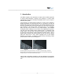
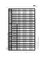
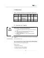
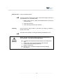
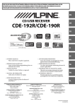
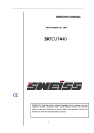
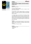
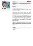
Wilson Tool International Ltd User manual _____________________________ Wilson Tapping Tool www.sm-tech.ro 01/09 __________________________________________________________________ All brand and product names are trademarks or registered trademarks of the owner concerned. 1st published 2009, edition date 01/09 © Wilson Tool International (Europe) Ltd., SN3 4TQ Swindon All rights reserved, including those of the translation. No part of this manual may be reproduced in any form (printed, photocopy, microfilm or any other process) or processed, duplicated or distributed by means of electronic systems without written permission of Wilson Tool Ltd, Swindon. We reserve right to make technical changes and to amend errors/omissions. Subject to alteration without notice. 2 __________________________________________________________________ Contents 1. Introduction ......................................................................... 4 2. Tool Information .................................................................. 6 2.1. Tapping tool construction .............................................. 7 2.2. Part numbers – overview ............................................... 8 2.3. Drive ........................................................................... 10 2.4. Lubrication of the tap ................................................... 10 2.5. Safety devices ............................................................. 11 3. Tool presetting................................................................... 12 4. Tool programming parameters ......................................... 15 5. 6. 4.1. Parameters ................................................................. 15 4.2. Pre-punching............................................................... 16 4.3. Programming parameters for tapping in flat sheets ..... 16 4.4. Programming parameters for tapping in extrusions ..... 18 Maintenance....................................................................... 20 5.1. Lubrication unit – tapping ............................................ 20 5.2. Tapping tool drive........................................................ 25 Freeing cycle ..................................................................... 26 3 __________________________________________________________________ 1. Introduction The Wilson Tapping Tool represents a unique and innovative approach to sheet metal fabrication, bringing more efficiency to sheet metal manufacturing through the forming of threaded holes on your Trumpf or Pullmax punch press. The technology of thread tapping produces no chips, since material is displaced (pushed out of the way) and not cut. The teeth on the tap are pressed into the pre-punched core hole. The material pushed out in this process is pressed into the free thread gaps on the tool, thus forming the core diameter of the formed thread. The thread gap is not completely filled, but this has no effect on the thread function. The material undergoes strain hardening in the course of the displacement process. The gain flow with thread forming remains intact in comparison with thread cutting. For this reason, the tensile strength of the formed thread is higher than the strength of taps produced by thread cutting. With a higher tensile strength, the formed thread can then be used to replace weld nuts, which are in many cases unsuitable due to heat related distortion of the sheet. In summary, thread forming technology saves your production costs and machining time. Figure 1 Figure 2 Photomicrographs show grain structures of cut (Fig. 1) and formed (Fig. 2) threads. Displacement of metal during the forming process results in threads that are generally stronger and have a smooth, burnished surface finish. This manual is intended to explain the use and limitations of the Wilson Tapping Tool. Please read all instructions carefully before operating this tool. 4 __________________________________________________________________ Writing conventions Symbols used in this manual have the following meanings: indicates actions to be taken. Attention! Warns of a hazardous situation that could result in damage to the product or components. Caution! Warns of the possibility of serious damage and injury. Indicates interesting tips and additional information 5 __________________________________________________________________ 2. Tool Information Wilson Tapping Tools are available in two models; designed for Group I and Group H machines: Group I Model Group I machines (newer group) TruPunch 1000/TC 1000R, TC 2000R, TruPunch 2020/TC 2020R, TruPunch 3000/TC 3000R, TruPunch 5000/TC 5000R, TruMatic 3000/ TC 3000L, TruMatic 6000/TC 6000L and Pullmax 520, 530, 720 & 730. Figure 3 Group H Model Group H machines (older group) TC 190R, TC 200R, TC 500R, TC 600L, TC 240R, TC 260R Figure 4 Wilson Tapping Tools are designed for use in specific machine groups. Group I tools and Group H tools are not interchangeable. Attention! 6 __________________________________________________________________ 2.1. Tapping tool construction 1 2 3 4 5 Figure 5 A tapping tool consist of: 1. Punch body – Two types available: Type 1 (M2.5 - M5) thread range Type 2 (M6 - M10) thread range 2. Leadscrew 3. Tap 4. Spindle nut 5. Die 7 __________________________________________________________________ 2.2. Group I Model Part numbers – overview Group I machines: TruPunch 1000 / TC 1000R, TC 2000 R, TruPunch 2020 / TC 2020 R, TruPunch 3000 / TC 3000 R, TruPunch 5000 / TC 5000 R, TruMatic 3000 / TC 3000 L, TruMatic 6000 / TC 6000 L Type 1: Tapping Sizes from M2.5 to M5 Tapping dimension Tool assembly Punch assy. Tapping without module assembly* tapping module Tap Leadscrew Spindle nut Die assy. M2.5 x 0.45 26378 26382 26385 26418 26411 26404 26384 M3 x 0.5 26378 26382 26386 26419 26412 26405 26384 M4 x 0.7 26378 26382 26387 26420 26413 26406 26384 M5 x 0.8 26378 26382 26388 26421 26414 26407 26384 Spindle nut Die assy. (*) – Tapping module assembly consist of Tap, Leadscrew & Spindle nut Type 2: Tapping Sizes from M6 to M10 Tapping dimension Tool assembly Punch assy. Tapping without module assembly* tapping module Tap Leadscrew M6 x 1.0 26379 26383 26389 26422 26415 26408 26384 M8 x 1.25 26379 26383 26390 26423 26416 26409 26384 26379 26383 26391 26424 26417 26410 26384 M10 x 1.5 (*) – Tapping module assembly consist of Tap, Leadscrew & Spindle nut Using a Wilson Tapping Tool with M10 tap without gear lubrication can cause damage to the tool. All Wilson Tapping Tools are designed with grease nipples to top-up the gear lubrication. Please refill with grease when using an M10 tap. Attention! 8 __________________________________________________________________ Group H Model Group H machines: TC 190 R / TC 200 R / TC 500 R / TC 600 L Type 1: Tapping Sizes from M2.5 to M5 Tapping dimension Tool assembly M2.5 x 0.45 26376 26380 26385 26418 26411 26404 26384 M3 x 0.5 26376 26380 26386 26419 26412 26405 26384 M4 x 0.7 26376 26380 26387 26420 26413 26406 26384 26376 26380 26388 26421 26414 26407 26384 M5 x 0.8 Punch assy. Tapping without module assembly* tapping module Tap Leadscrew Spindle nut Die assy. (*) – Tapping module assembly consist of Tap, Leadscrew & Spindle nut Type 2: Tapping Sizes from M6 to M10 Tapping dimension Tool assembly Punch assy. Tapping without module assembly* tapping module Tap Leadscrew Spindle nut Die assy. M6 x 1.0 26377 26381 26389 26422 26415 26408 26384 M8 x 1.25 26377 26381 26390 26423 26416 26409 26384 26377 26381 26391 26424 26417 26410 26384 M10 x 1.5 (*) – Tapping module assembly consist of Tap, Leadscrew & Spindle nut Using a Wilson Tapping Tool with M10 tap without gear lubrication can cause damage to the tool. All Wilson Tapping Tools are designed with grease nipples to top-up the gear lubrication. Please refill with grease when using an M10 tap. Attention! 9 __________________________________________________________________ 2.3. Drive Vertical movement of the tap into the sheet is achieved through rotation of the C-axis and the gears within the tool. No programmed vertical movement of the C-axis is required to achieve vertical movement of the tap. Lubricate the drive every 40 operating hours. (See page 25.) Attention! 2.4. Lubrication of the tap Lubricant is applied automatically to the tap by the machine at the start of every tap cycle via bore holes in the tool body and stripper. bore holes for lubricating the thread Figure 6 Every 40 operating hours check the oil stream. (See page 20.) Attention! 10 __________________________________________________________________ 2.5. Safety devices The die is fitted with a pneumatic sensor which activates the FEED HOLD on the machine if the tap plunges too deeply into the die caused by over rotation of the tap, or if the leadscrew works itself free. This feature provides an additional safe guard against tool breakage. Pneumatic sensor Figure 7 11 __________________________________________________________________ 3. Tool presetting Before loading, presetting must be done as follows: 1. Turn the tool to the home position by holding the tool by the gear wheel and rotating the punch body until there is a click. Gear Wheel Punch Body Figure 8 2. Check the values of diameter printed on the tap. They must correspond to those on the spindle nut and leadscrew. 3. Push the tap into the leadscrew until it locks in place. 12 __________________________________________________________________ Leadscrew Setting gauge Spindle nut 15.5 mm Figure 9: Setting the length of the tapping module assembly 4. Set size 15.5mm (+/- 0.1mm) between the nut and gearwheel on the leadscrew using the setting gauge. (Cat. No.: 26448) Double check: The tip of the tap must be close to flush with the front face of the spindle nut. Remove the setting gauge when presetting of the tapping module assembly is complete. Attention! 13 __________________________________________________________________ 5. Insert the tapping module assembly into the punch body. Pull the securing pin back, and then push the tapping module assembly into the punch body. Ensure that the slot on the tapping module assembly lines up with the securing pin. Tapping Module Assembly Pin & Slot Securing Pin Figure 10 6. Release the securing pin. Ensure that the following is true: a) The securing pin is engaged in the slot on the tapping module assembly b) The securing pin has returned to its home position c) The tapping module assembly is locked into the punch body. 14 __________________________________________________________________ 4. Tool programming parameters The following section contains the parameters and data required to program the Wilson Tapping Tool. Specific information regarding the machine controller is not included within this manual. Please see your machine’s Operator Manual for detailed information on programming the tapping tool on your machine. 4.1. Parameters The quality and accuracy of a formed thread depends on the parameters listed below: • Pre-punch diameter • Type of Material • Rotational speed • Type of sheet Pre-punch diameter The tolerance of the pre-punched hole is critical to ensure a good quality formed thread. Type of material The pre-punch diameter can be reduced for soft material (e.g. aluminium) due to greater deformability. Rotational speed The rotational speed of the C axis has to be optimised to suit the thread dimension and the type of material. Type of sheet Threads can be formed into extrusions to allow tapping in thinner sheet materials. 15 __________________________________________________________________ 4.2. Pre-punching If the punch diameter is smaller than the material thickness ‘s’, follow the instructions listed below: s < 4 mm – use stubby style tool s > 4 mm – use active presser foot Table of ratios In normal punching conditions the ratios between punch diameter and material thickness are: aluminium – diameter at least equal to material thickness mild steel – diameter at least 1.5 times material thickness stainless steel – diameter at least 2 times material thickness Stubby style tooling must be used for any pre-punch falling outside the criteria above. Stubby style tooling is not covered by Wilson Tool’s normal warranty. 4.3. Programming parameters for tapping in flat sheets Pre-punch diameter The following tables list the pre-punch diameters to be used for tapping. Pre-punch diameters vary depending on the desired thread, the type of material and the material thickness. Rotational speed The maximum input value depends on the type of material. Number of revolutions The values in parentheses are only theoretical; e.g. it is not possible to tap an M10 thread in a 1 mm sheet. When tapping in material with sheet distortion (i.e. not totally flat), increase the working position offset and number of revolutions to compensate for the height of the distortion. Attention! Maximum number of revolutions The leadscrew is secured against incorrect input of the number of revolutions by an override clutch. The values are for orientation purposes only. 16 17 M2.5 M3 M4 M5 M6 M8 M10 26418 26419 26420 26421 26422 26423 26424 Pre-punch diameter [mm] 2.3 2.8 3.7 4.65 5.55 7.4 9.3 Max. material thickness [mm] 3 3 4 5 6 8 8 Rotational speed [rpm] 180/* 180/* 180/* 180/* 180/* 180/* 180/* Pre-punch diameter [mm] 2.3 2.8 3.7 4.65 5.55 7.4 9.3 3 3 4 5 6 8 8 Max. material thickness [mm] 180/* 180/* 180/* 180/* 180/* 180/* 180/* ( ) – The values in parentheses are only theoretical s – Material thickness [mm] X5CrNi18-10 (1.4301) Stainless Steel 2.3 2.8 3.7 4.65 5.55 7.4 9.3 Pre-punch diameter [mm] S235JR (1.0038) Mild steel 2.5 3 4 5 6 8 6 Max. material thickness [mm] EN AW-5754 (3.3535) Alluminium alloy Rotational speed [rpm] (*) – Maximum rotational speed [rpm] for TruPunch 5000 / TC 5000 R, TruMatic 6000 / TC 6000 L can be increased to 330 rpm Thread dimension Tap Part No. 115 96 72 58 176 132 106 Rotational speed [rpm] Table 5 Programming parameters for tapping in flat sheets 1.1 1.0 (0.9) (0.8) (2.0) (1.5) (1.2) s=1 1.3 1.2 1.0 (1.0) (2.3) (1.8) (1.2) s=2 1.5 1.4 1.1 1.1 (2.7) (2.1) (1.5) s=3 1.7 1.6 1.3 1.2 3.0 (2.4) (1.8) s=4 Number of revolutions 1.8 1.8 1.4 1.3 3.3 2.6 2.2 s=5 2.2 2.0 1.5 1.4 3.6 2.9 2.4 s=6 4.3 3.5 2.7 s=8 2.5 2.3 1.7 1.5 4.3 3.5 2.9 Maximum revolutions __________________________________________________________________ __________________________________________________________________ 4.4. Programming parameters for tapping in extrusions The Wilson Tapping Tool can also be used to tap into extrusions. This is particularly useful for producing taps in thinner materials. (Note: The recommended maximum material thickness for extrusions is 3mm). Please contact the Wilson Tool Sales Desk or your local Sales Engineer for more information about extrusions. When determining the working position offset for tapping into extrusions, the height of the formed area must be considered. s h offset Attention! h – extrusion height s – material thickness Figure 11 Determining working position offset The working position offset is shown in the diagram above (shown as “offset”) Number of revolutions The number of revolutions must be determined for the full height of the extrusion from the bottom of the sheet. (Shown as “h” on the diagram above). When tapping in material with sheet distortion (i.e. not totally flat), increase the working position offset and number of revolutions to compensate for the height of the distortion. Attention! In addition to programming information for tapping in extrusions, the following table also includes data on the extrusion pre-punch required. 18 19 Material thickness [mm] 1.0 1.5 1.0 1.5 2.0 1.0 1.5 2.0 2.5 1.0 1.5 2.0 2.5 3.0 1.0 1.5 2.0 2.5 3.0 1.5 2.0 2.5 3.0 1.5 2.0 2.5 3.0 Pre-punch diameter [mm] 1.0 1.5 1.8 1.8 2.3 2.3 2.5 2.7 2.7 3.0 3.3 3.8 3.0 4.0 5.0 5.0 5.5 7.0 7.0 7.0 - Rotational speed [rpm] 180/* 180/* 180/* 180/* 180/* 180/* 180/* Pre-punch diameter [mm] 1.0 1.5 1.5 1.5 1.5 2.0 1.5 2.0 2.5 2.5 2.5 2.0 2.5 2.5 3.0 3.5 3.0 3.5 3.5 4.5 4.5 5.0 5.0 7.0 7.0 7.0 7.0 Rotational speed [rpm] 180/* 180/* 180/* 180/* 180/* 180/* 180/* 1.0 1.5 1.5 1.5 2.0 1.5 2.5 2.5 3.0 3.5 3.0 4.5 4.5 7.0 7.0 - Pre-punch diameter [mm] 106 132 176 58 72 96 115 Tool diameter [mm] 9.3 7.4 5.55 4.65 3.7 2.8 2.3 26478 26477 26476 26475 26474 26473 26472 3.5 4.1 4 4.6 5.2 4.9 5.5 6.1 6.7 5.85 6.45 7.05 7.65 8.25 6.75 7.35 7.95 8.55 9.15 9.2 9.8 10.4 11 11.1 11.7 12.3 12.9 26479 26480 26481 26482 26483 26484 26485 26486 26487 26488 26489 26490 26491 26492 26493 26494 26495 26496 26497 26498 26499 26500 26501 26502 26503 26504 26505 Extrusion punch (Part No.) (1.2) (1.5) (2.0) (0.8) (0.9) (1.0) (1.1) h=1 (1.2) (1.8) 2.3 1.0 1.0 1.2 1.3 h=2 1.8 2.1 2.7 1.1 1.1 1.4 1.5 h=3 ( ) – The values in parentheses are only theoretical h – overall extrusion height [mm] 2.0 2.4 3.0 1.2 1.3 1.6 1.7 h=4 Number of revolutions (*) – Maximum rotational speed [rpm] for TruPunch 5000 / TC 5000 R, TruMatic 6000 / TC 6000 L can be increased to 330 rpm M10 M8 M6 M5 M4 M3 M2.5 Rotational speed [rpm] X5CrNi18-10 (1.4301) Stainless steel Drawing pierc. punch [mm] S235JR (1.0038) Mild steel EN AW-5754 (3.3535) Aluminium alloy Extrusion die insert (Part No.) Thread dimension Drawing pierc. die [mm] Table 6 Programming parameters for tapping in extrusions 2.2 2.6 3.3 1.3 1.4 1.8 (1.8) h=5 2.4 2.9 3.6 1.4 1.5 (2.0) (2.2) h=6 2.7 3.5 4.3 - - - - h=8 2.9 3.5 4.3 1.5 1.7 2.3 2.5 Max rev. __________________________________________________________________ __________________________________________________________________ 5. Maintenance Table 7: Lubricants required for use with the Wilson Tapping Tool. Lubrication Point Capacity Lubricant Quantity Cat. No. Lubrication tapping unit 2.5 l X-Cel Tap Lubricant Fe (mild steel, stainless steel) X-Cel Tap Lubricant Al (aluminium and aluminium alloys) X-Drive grease 1l 55267 1l 55268 22 100ml 55269 160 Tapping tool drive Kinematic Viscosity at 40 °C 22 5.1. Lubrication unit – tapping There is a high risk of injury when carrying out maintenance on a live machine. Consider the following actions Attention! Complete a risk assessment before starting any maintenance task. Place a sign on the machine informing other staff that maintenance work is being carried out. Appoint a supervisor. Ensure no one is within the danger zone before starting the machine. The quantity of oil in the lubricant reservoir is sufficient for about 20,000 strokes. Check oil stream Every 40 operating hours. The oil must hit the tap in a sharp, straight jet. After several oil pulses, the oil must drip from the tap. If this is not the case, air has entered the system and oil cannot be transported reliably. Possible causes: • The oil reservoir is empty. • The hose seal in the nozzle is defective. • The nozzle is blocked by contamination 20 __________________________________________________________________ Check oil level Every 40 operating hours. To ensure air does not enter the system, ensure the lubricant reservoir is never allowed to run completely empty. 1. Switch off the machine; switch off the MAIN SWITCH, lock it and remove the key. 2. Open the front hood. 3. Check the filling volume of the reservoir. Bleeding The oil reservoir must be bled if it has been run empty by mistake or another one is used. The machine is switched on during the following maintenance work. There is a high risk of injury when carrying out maintenance on a live machine. Consider the following actions Attention! Complete a risk assessment before starting any maintenance task. Place a sign on the machine informing other staff that maintenance work is being carried out. Appoint a supervisor. Ensure no one is within the danger zone before starting the machine. 21 __________________________________________________________________ Figure 12 1 1. Open the hose fitting on the basic nozzle body (1). Do not remove the hose. 2. Exit the danger zone and press the ACKNOWLEDGE LIGHT BARRIER foot switch. 3. Select Operation > Set-up > Switch elements. 4. Select the “General” switch element. 5. Select the “Lubricate tapping tool” switch element approximately 10 times until no more bubbles are visible in the hose. 6. Close the hose fitting. Illustrations are from a Trumpf 1000. Design may vary depending on machine model. 22 __________________________________________________________________ Refill with oil At less than ¼ of the filling volume. Figure 13 1 2 1. Switch off the machine; switch off the MAIN SWITCH, lock it and remove the key. 2. Open the front hood. 3. Undo the quick-release coupling(2) and pull out the reservoir(1). 4. Open the filling nozzle. 5. Remove and clean the strainer basket. 6. Insert the strainer basket. 7. Pour in oil. 8. Push in the container and lock the quick-release coupling into place. 9. Bleed it if necessary. 10. Close the front hood. 23 __________________________________________________________________ Replace hose seal Every 500 operating hours and whenever the nozzle is removed. The hose seal is a wearing part and must be replaced at the specified intervals and each time the nozzle is replaced. Figure 14 1 2 1. Switch off the machine; switch off the MAIN SWITCH, lock it and remove the key. 2. Undo the screw (1) and remove the basic nozzle body. 3. Unscrew the nozzle (2) from the basic nozzle body. 4. Pull the hose seal off the basic nozzle body. 5. The new hose seal must be pushed up to the collar on the basic nozzle body and must close flush with the nozzle at the front. The hose seal may have to be shortened. 6. Screw on the nozzle. 24 __________________________________________________________________ 5.2. Tapping tool drive Lubricate the drive every 40 operating hours. Attention! The tapping tool planetary gearbox must be lubricated with grease every 40 hours using the grease nipples on the back of the punch body. 25 __________________________________________________________________ 6. Freeing cycle The freeing cycle is necessary, if the programme was interrupted by an external interference (e.g. EMERGENCY STOP), because a mechanical connection between the material and tool occurs during tapping. The tapping tool is released from the sheet by the C axis rotation. Equal quantity of revolutions is required as have been programmed. In some cases (e.g. over rotation of the tap and consequential activation of the override clutch), the number of revolutions necessary for the thread former release not according to programmed. Therefore is necessary to check position of the tap by an operator, if it is outside, or still inside the sheet. If the tap is still inside the sheet then activate softkey (IN SHEET?), until the softkey (OUT OF SHEET?) can be actuated. The error message REMOVE TOOL informs the user that the freeing cycle has ended. It is necessary to check the tool after any program interruption. The opening of the tool clamp deletes the error message. 26